


 Loading...
Operating Instructions 26”/32” DIAGONAL LCD TV Manual de instrucciones TV DE LCD DE 26”/32” DIAGONAL
Model No. Número de modelo
TC-26LE70 TC-32LE70
Quick Start Guide
(See page 6)
Guía de inicio rápido
(vea la página 6)
 For assistance (U.S.A.), please call:
1-800-211-PANA (7262)
or visit us at www.panasonic.com/contactinfo
 For assistance (Puerto Rico), please call:
787-750-4300
or visit us at www.panasonic.com
 For assistance (Canada), please call:
1-800-561-5505
or visit us at www.panasonic.ca
 Para solicitar ayuda (EE.UU.), llame al:
1-800-211-PANA (7262)
ó visítenos en www.panasonic.com/contactinfo
 Para solicitar ayuda (Puerto Rico), llame al:
787-750-4300
ó visítenos en www.panasonic.com
English
Español
Please read these instructions before operating your set and retain them for future reference. The images shown in this manual are for illustrative purposes only.
Lea estas instrucciones antes de utilizar su televisor y guárdelas para consultarlas en el futuro. |
TQB2AA0831 |
Las imágenes mostradas en este manual tienen solamente fines ilustrativos. |

Turn your own living room into a movie theater!
Experience an amazing level of multimedia excitement
HDMI, the HDMI logo and High-Definition Multimedia Interface are trademarks
or registered trademarks of HDMI Licensing LLC.
2
HDAVI
Control™
HDAVI Control™ is a trademark of Matsushita Electric Industrial Co., Ltd.
EZ Sync™
EZ Sync™ is a trademark of Matsushita Electric Industrial Co., Ltd.

Enjoy rich multimedia
Camcorder
Set Top Box
VCR |
DVD player |
Amplifier Home theater
system
DVD recorder
Manufactured under license from Dolby Laboratories. DOLBY and the double-D symbol are trademarks of Dolby Laboratories.
Contents
Please read before using the unit
•Safety Precautions······································· 4
Quick Start Guide
•
•Accessories/Optional Accessory ··· 6
•Before Connection························ 8
•Basic Connection·························· 9
•Identifying Controls ···················· 15 First Time Setup·························· 16
Enjoy your TV!
Basic Features
•
•Watching TV··············································· 18
Watching Videos and DVDs······················· 20
Advanced Features
•How to Use Menu Functions
•(picture, sound quality, etc.) ······················· 22
•EZ SyncTM “HDAVI ControlTM”····················· 26
•Lock ··························································· 28
•Editing and Setting Channels ···················· 30
•Input Labels/Monitor out/Closed Caption······· 32
•Using Timer················································ 34
Recommended AV Connections ················ 36
FAQs, etc.
•
•Ratings List for Lock ·································· 38
•Technical Information································· 39
•Maintenance ·············································· 41
•FAQ···························································· 42
•Specifications············································· 44
•Limited Warranty (for U.S.A.)····················· 45
•Customer Services Directory (for U. S. A.)···· 46 Limited Warranty (for Canada)··················· 47
Start Quick
Guide
Viewing
Advanced
.etc FAQs,
3

Safety Precautions
CAUTION
RISK OF ELECTRIC SHOCK
DO NOT OPEN
WARNING: To reduce the risk of electric shock, do not remove cover or back. No user-serviceable parts inside. Refer servicing to qualified service personnel.
The lightning flash with arrow head within a triangle is intended to tell the user that parts inside the product are a risk of electric shock to persons.
The exclamation point within a triangle is intended to tell the user that important operating and servicing instructions are in the papers with the appliance.
Note to CATV System Installer
This reminder is provided to direct the CATV system installer’s attention to Article 820-40 of the NEC that provides guidelines for proper grounding and, in particular, specifies that the cable ground shall be connected to the grounding system of the building, as close to the point of cable entry as practical.
Secure Ventilation
Slots and openings in the cabinet and the back or bottom are provided for ventilation, and to ensure reliable operation of the LCD TV and to protect it from overheating. These openings must not be blocked or covered. There should be at least 10 cm of space from these openings. The openings should never be blocked by placing the LCD TV on a bed, sofa, rug or other similar surface. This LCD TV should not be placed in a built-in installation such as a bookcase unless proper ventilation is provided.
Important Safety Instructions
1)Read these instructions.
2)Keep these instructions.
3)Heed all warnings.
4)Follow all instructions.
5)Do not use this apparatus near water.
6)Clean only with dry cloth.
7)Do not block any ventilation openings. Install in accordance with the manufacturer’s instructions.
8)Do not install near any heat sources such as radiators, heat registers, stoves, or other apparatus (including amplifiers) that produce heat.
9)Do not defeat the safety purpose of the polarized or grounding-type plug. A polarized plug has two blades with one wider than the other. A grounding type plug has two blades and a third grounding prong. The wide blade or the third prong are provided for your safety. If the provided plug does not fit into your outlet, consult an electrician for replacement of the obsolete outlet.
10)Protect the power cord from being walked on or pinched particularly at plugs, convenience receptacles, and the point where they exit from the apparatus.
11)Only use attachments / accessories specified by the manufacturer.
12) Use only with the cart, stand, tripod, bracket, or table specified by the manufacturer, or sold with the apparatus. When a cart is used, use caution when moving the cart / apparatus combination to avoid injury from tip-over.
13)Unplug this apparatus during lightning storms or when unused for long periods of time.
14)Refer all servicing to qualified service personnel. Servicing is required when the apparatus has been damaged in any way, such as power-supply cord or plug is damaged, liquid has been spilled or objects have fallen into the apparatus, the apparatus has been exposed to rain or moisture, does not operate normally, or has been dropped.
15)Operate only from the type of power source indicated on the marking label. If you are not sure of the type of power supplied to your home consult your television dealer or local power company.
16)Follow all warnings and instructions marked on the LCD TV.
17)Never push objects of any kind into this LCD TV through cabinet slots as they may touch dangerous voltage points or short out parts that could result in a fire or electric shock. Never spill liquid of any kind on the LCD TV.
18)If an outside antenna is connected to the television equipment, be sure the antenna system is grounded so as to provide some protection against voltage surges and built up static charges.
In the U.S. Section 810-21 of the National Electrical Code provides information with respect to proper grounding of the mast and supporting structure, grounding of the lead-in wire to an antenna discharge unit, size of grounding conductors, location of antenna discharge unit, connection to grounding electrodes, and requirements for the grounding electrode.
EXAMPLE OF ANTENNA GROUNDING AS PER (NEC) NATIONAL
ELECTRICAL |
ANTENNA |
CODE |
LEAD-IN WIRE |
GROUND CLAMP |
|
|
ANTENNA |
ELECTRIC |
DISCHARGE UNIT |
(NEC SECTION 810-20) |
|
SERVICE |
|
EQUIPMENT |
GROUNDING |
|
CONDUCTORS |
|
(NEC SECTION 810-21) |
|
GROUND CLAMPS |
|
POWER SERVICE GROUNDING |
|
ELECTRODE SYSTEM |
|
(NEC ART 250, PART H) |
4

19)An outside antenna system should not be located in the vicinity of overhead power lines, other electric light, power circuits, or where it can fall into such power lines or circuits. When installing an outside antenna system, extreme care should be taken to keep from touching such power lines or circuits as contact with them might be fatal.
20)Unplug this LCD TV from the wall outlet and refer servicing to qualified service personnel under the following conditions:
a.When the power cord or plug is damaged or frayed.
b.If liquid has been spilled into the LCD TV.
c.If the LCD TV has been exposed to rain or water.
d.If the LCD TV does not operate normally by following the operating instructions.
Adjust only those controls that are covered by the operating instructions as improper adjustment of other controls may result in damage and will often require extensive work by a qualified technician to restore the LCD TV to normal operation.
e.If the LCD TV has been dropped or the cabinet has been damaged.
f.When the LCD TV exhibits a distinct change in performance - this indicates a need for service.
21)When replacement parts are required, be sure the service technician uses replacement parts specified by the manufacturer that have the same characteristics as the original parts. Unauthorized substitutions may result in fire, electric shock, or other hazards.
22)WARNING: TO REDUCE THE RISK OF FIRE OR ELECTRIC SHOCK, DO NOT EXPOSE THIS APPARATUS TO RAIN,
MOISTURE, DRIPPING OR SPLASHING.
DO NOT PLACE LIQUID CONTAINERS (FLOWER VASES, CUPS, COSMETICS, ETC.) ABOVE THE SET (INCLUDING ON SHELVES ABOVE, ETC.).
23) WARNING: SMALL PARTS CAN PRESENT CHOKING HAZARD IF ACCIDENTALLY SWALLOWED. KEEP SMALL
PARTS AWAY FROM YOUNG CHILDREN.
DISCARD UNNEEDED SMALL PARTS AND OTHER OBJECTS, INCLUDING PACKAGING MATERIALS AND PLASTIC BAGS/SHEETS TO PREVENT THEM FROM BEING PLAYED WITH BY YOUNG CHILDREN, CREATING THE POTENTIAL RISK OF SUFFOCATION.
24) CAUTION: TO PREVENT ELECTRIC SHOCK, DO NOT USE THIS PLUG WITH A RECEPTACLE OR OTHER OUTLET
UNLESS THE BLADES CAN BE FULLY INSERTED TO PREVENT BLADE EXPOSURE.
25)CAUTION: USE WITH OTHER STAND MAY RESULT IN INSTABILITY POSSIBLY CAUSING INJURY.
26)CAUTION: DANGER OF EXPLOSION IF BATTERY IS INCORRECTLY REPLACED. REPLACE ONLY WITH THE SAME
OR EQUIVALENT TYPE.
27) CAUTION: This LCD TV is for use only with the following optional accessory. Use with any other type of optional accessories may cause instability which could result in the possibility of injury.
(All of the following accessories are manufactured by Matsushita Electric Industrial Co., Ltd.)
•Wall-hanging bracket (Vertical): TY-WK32LR2W
Always be sure to ask a qualified technician to carry out set-up.
NOTE: This equipment is designed to operate in North America and other countries where the broadcasting system and AC house current are exactly the same as in North America.
■This product utilizes tin-lead solder and has a fluorescent lamp containing a small amount of mercury. Disposal of these materials may be regulated in your community due to environmental considerations. For disposal or recycling information, please contact your local authorities or the Electronics Industries Alliance: www.eiae.org.
FCC STATEMENT
This equipment has been tested and found to comply with the limits for a TV Broadcast Receiver, pursuant to Part 15 of the FCC Rules. These limits are designed to provide reasonable protection against harmful interference in a residential installation. This equipment generates, uses and can radiate radio frequency energy and, if not installed and used in accordance with the instructions, may cause harmful interference to radio communications. However, there is no guarantee that interference will not occur in a particular installation. If this equipment does cause or receive interference, which can be determined by turning equipment off and on, the user is encouraged to try to correct the interference by one or more of the following measures:
Reorient or relocate the TV antenna.
Increase the separation between TV and other equipment.
Connect TV into separate outlet from other equipment.
Consult the dealer or an experienced radio / TV technician for help.
FCC Caution: |
Any changes or modifications not expressly approved by the party responsible for compliance could void the |
|
user’s authority to operate this equipment. |
5

Accessories/Optional Accessory

 Check you have all the items shown.
Accessories
□Remote Control |
□Batteries for the Remote |
Transmitter |
Control Transmitter (2) |
•N2QAYB000103 |
•AA Battery |
|
|
|
|
|
|
|
|
|
|
|
|
|
|
|
|
|
|
|
|
|
|
|
|
|
|
|
|
|
|
□Product Registration Card |
□Customer Care Plan Card |
||||
(U.S.A.) |
(U.S.A.) |
||||
□HDMI Cable
□Operating Instructions □Notice sheet (Demo mode) □Warranty Card (Mexico)
□Quick Setup Guide
(For viewing HD programming)
1 |
|
Installing remote’s batteries |
Open |
2 |
|
|
|
Close
Hook
Note the correct polarity (+ or -).
Caution
•Incorrect installation may cause battery leakage and corrosion, resulting in damage to the remote control unit.
•Do not mix old and new batteries.
•Do not mix different battery types (such as alkaline and manganese batteries).
•Do not use rechargeable (Ni-Cd) batteries.
•Do not burn or break batteries.
Location
Place the TV at a comfortable distance for viewing. Avoid placing it where sunlight or other bright light (including reflections) will fall on the screen.
Use of some types of fluorescent lighting can reduce remote control transmitter range.
Adequate ventilation is essential to prevent an internal component failure. Keep away from areas of excessive heat or moisture.
6
Optional accessory (When installing on the wall)
Please contact your nearest Panasonic dealer to purchase the recommended wall-hanging bracket. For additional details, please refer to the wall-hanging bracket installation manual.
Wall-hanging bracket (vertical)
•TY-WK32LR2W
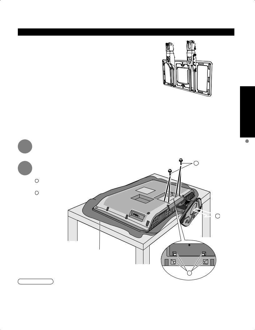
Before mounting the TV on the wall, you must remove the TV-Stand from the TV. Follow the steps below:
1 |
Disconnect all the cables from the TV. |
|
2 |
Remove the TV-Stand. |
A |
|
A Remove four screws
B Pull out the TV-Stand
 B
B
Foam mat or thick soft cloth
A
WARNING
•Failure to use a Panasonic bracket or choosing to mount the unit yourself will be done at the risk of the consumer. Any damage resulting from not having a professional installer mount will void your unit’s warranty.
•Always be sure to ask a qualified technician to carry out set-up.
Incorrect fitting may cause equipment to fall, resulting in injury and product damage.
•Do not mount this LCD Television directly below ceiling lights (such as spotlights, floodlights, or halogen lights) which typically give off high heat. Doing so may warp or damage plastic cabinet parts.
Start Quick
Accessory Accessories/Optional Guide
7
Before Connection
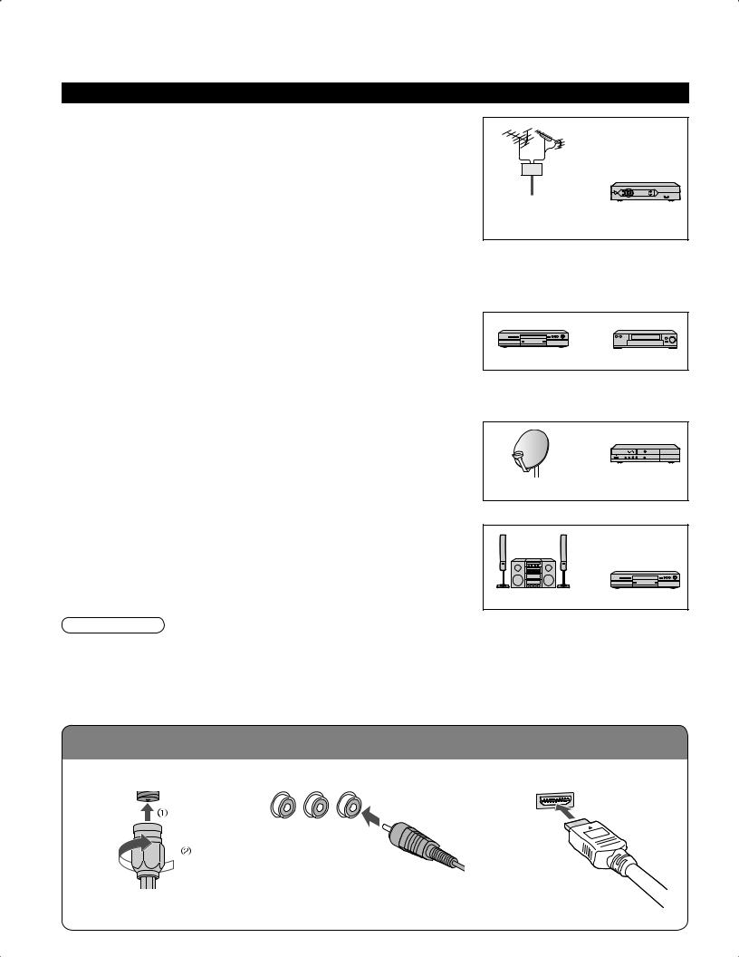
Connected Equipment Introduction (Signal source)
■Watching TV |
|
|
VHF/UHF Antenna |
|
|
••NTSC (National Television System Committee): |
|
|
Conventional broadcasting |
or |
|
•ATSC (Advanced Television Systems Committee): |
|
|
|
|
|
Digital TV Standards include digital high-definition television (HDTV), |
|
|
standard-definition television (SDTV), data broadcasting, multi-channel |
VHF/UHF Antenna |
Cable Box/ |
surround-sound audio and interactive television. |
||
Cable Box/Cable |
|
Cable |
••You need to subscribe to a cable TV service to enjoy viewing their |
|
|
programming. |
|
|
•You can enjoy high-definition programming by subscribing to a high-definition cable box. The connection can be |
||
done with the use of HDMI or Component Video cable. |
|
|
■Recording/playing back with DVD recorder or VCR |
|
|
DVD Recorder |
or |
|
•This source has higher resolution through interlace or progressive signal. |
DVD Recorder |
VCR |
Connection can be done with the use of Component Video or HDMI cable. |
||
•VCRConnection can be done with the use of an RF cable and Composite Video/S Video cable. |
|
|
■Watching Satellite
•You can enjoy high-definition programming by subscribing to high-definition satellite source. Connection can be done with the use of HDMI or Component Video cable.
Satellite Antenna |
Satellite |
Receiver |
■Enjoying Home theater and DVD recorder with HDMI connection
Home theater and DVD Recorder |
|
|
•HDMI connection enables you to enjoy higher quality audio and video with |
|
|
a single cable. |
Home Theater |
DVD Recorder |
|
Note
•If your Panasonic DVD Recorder is compatible with EZ Sync (HDAVI control 2), you can operate your Panasonic DVD Recorder with this TV’s remote control (p. 21 EZ SyncTM).
•All cables and external equipment shown in this book are not supplied with the TV.
•For the details of the external equipment’s connections, please refer to the operating manuals of the equipment.
Reference of connection
■Antenna terminal |
■Pin terminals |
■HDMI terminal |
||
|
|
red blue green |
|
|
|
|
green |
|
|
• |
Firmly tighten by hand. |
Match colors of plugs and terminals. |
• |
Insert firmly. |
|
••Insert firmly. |
|
||
8 |
|
|
|
|

Basic Connection
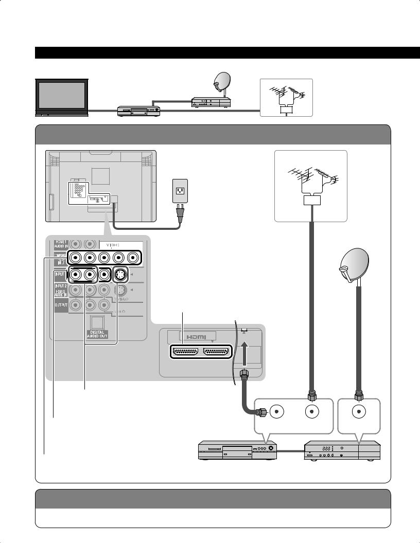
Example 1 |
Connecting Antenna (To watch TV) |
TV |
|
|
VHF/UHF Antenna |
|
Cable TV |
|
To connect antenna terminals |
VHF/UHF Antenna
AC 120 - 127 V
60 Hz
Cable TV or
|
|
|
Power Cord |
|
|
|
(Connect after all the |
Back of the TV |
|
|
other connections.) |
|
|
|
|
|
|
|
Antenna |
|
|
|
terminal |
AV |
IN |
|
ANT |
1 |
2 |
SERVICE ONL Y |
This slot is for services by the Panasonic dealer.
(If no Cable Box)
or
ANT OUT ANT IN
•If using Cable Box
•Set the TV channel to CH3 or CH4.
Cable Box
Note
•For additional assistance, visit us at: www.panasonic.com www.panasonic.ca
Start Quick
TV) + (Antenna Connection Basic Guide
Connection Before
9

Basic Connection (Continued)
Example 2 Connecting DVD recorder (VCR) (To record/playback)
TV
DVD Recorder or
VCR
VHF/UHF Antenna
To connect antenna terminals
VHF/UHF Antenna
AC 120 - 127 V
60 Hz
Power Cord
Back of the TV
To use HDMI |
|
|
terminals |
|
|
(next page) |
|
Antenna |
|
|
|
|
|
terminal |
AV |
IN |
ANT |
1 |
2 |
|
To use S VIDEO terminals (next page)
To use OUTPUT terminals (p. 36, 37)
To use COMPOSITE terminals (next page)
To use COMPONENT terminals (next page)
ANT OUT ANT IN
DVD Recorder or VCR (with TV tuner)
10

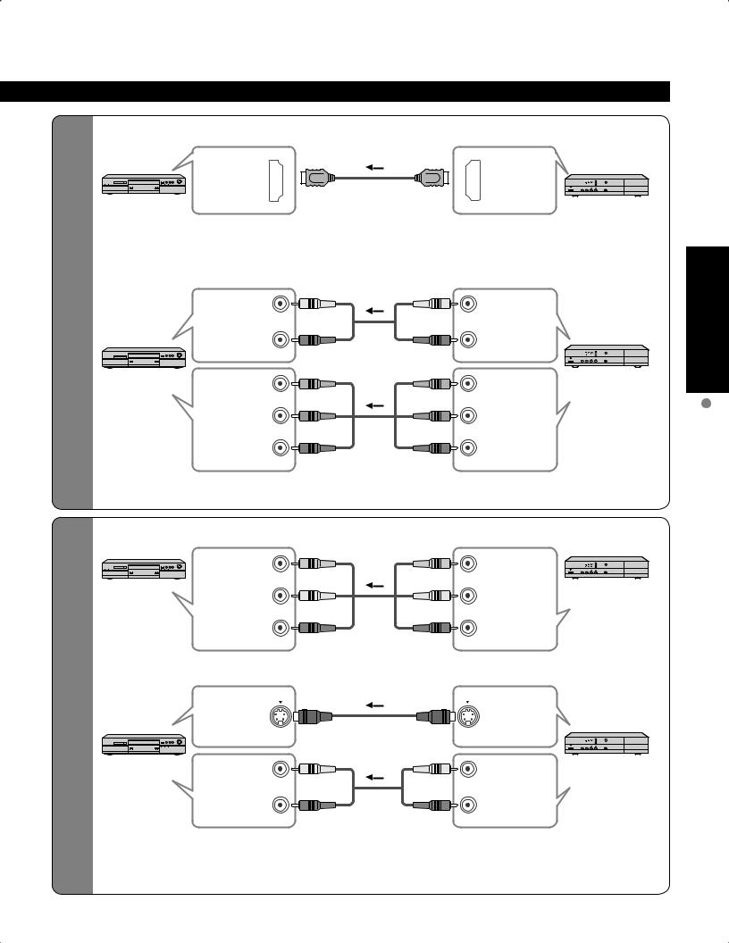
■To use HDMI terminals
|
AV |
IN |
|
|
|
|
|
1 |
2 |
|
|
HDMI |
|
|
|
|
|
|
|
|
|
|
|
|
|
AV OUT |
DVD Recorder |
|
|
|
|
|
|
|
High |
•sound.Connecting to HDMI terminals will enable you to enjoy high-definition digital images and high-quality |
|||||
■To use COMPONENT terminals |
|
|
|
|
||
- |
|
|
|
L |
|
|
Definition |
|
green |
|
|
|
|
|
|
Y |
|
|
||
|
|
white |
white |
white |
AUDIO |
|
|
|
red |
|
R |
OUT |
|
|
|
red |
|
|
|
|
|
|
|
red |
|
|
|
|
|
|
green |
green |
|
DVD Recorder |
|
|
|
|
PB |
COMPONENT |
|
|
|
|
|
|
||
|
|
blue |
blue |
blue |
VIDEO OUT |
|
|
|
|
|
|||
|
|
|
|
PR |
|
|
|
|
red |
red |
red |
|
|
|
•Recorders may also be connected to COMPOSITE or S VIDEO terminals. (see below) |
|
||||
■To use COMPOSITE terminals
|
|
yellow |
yellow |
yellow |
|
DVD Recorder |
|
|
|
|
L |
COMPOSITE |
or |
Standard |
■ |
white |
white |
white |
OUT |
|
|
|
R |
S VIDEO |
VCR |
||
|
|
|
|
|
||
|
|
red |
red |
red |
|
|
|
|
|
|
|||
|
|
To use S VIDEO terminals |
|
|
|
|
- |
|
|
|
|
OUT |
|
Definition |
|
white |
white |
|
|
|
|
white |
|
DVD Recorder |
|||
|
|
|
|
|
|
|
|
|
|
|
L |
|
or |
|
|
|
|
|
|
|
|
|
|
|
|
AUDIO |
|
|
|
|
|
R |
OUT |
VCR |
|
|
red |
red |
red |
|
|
|
|
|
|
The S Video input will override the composite |
Connecting to S VIDEO terminals will enable |
•video signal when S Video cable is connected. |
•you to enjoy greater picture quality than using |
Connect either S Video or Video cable. |
Composite terminals. |
Note
•Some programs contain a copyright protection signal to prevent recording.
•When the copyright protection program is displayed, do not connect the other TV monitor through a VCR. Video signals fed through VCRs may be affected by copyright protection systems and the picture will be distorted on the other TV monitor.
Start Quick
Connection Basic Guide VCR) or Recorder DVD + (TV
11
Basic Connection (Continued)
Example 3 Connecting DVD recorder (VCR) and satellite receiver
TV |
Satellite |
|
DVD Recorder |
||
Receiver |
||
or |
|
|
VCR |
|
VHF/UHF Antenna
To connect antenna terminals
VHF/UHF Antenna
AC 120 - 127 V
60 Hz
Power Cord
Back of the TV
To use HDMI |
|
|
terminals |
|
|
(p. 11) |
|
Antenna |
|
|
|
|
|
terminal |
AV |
IN |
ANT |
1 |
2 |
|
To use S VIDEO terminals (p. 11)
To use COMPOSITE terminals |
ANT OUT |
ANT IN |
ANT IN |
(p. 11) |
|
|
|
To use COMPONENT terminals |
|
|
|
(p. 11) |
DVD Recorder or VCR |
Satellite Receiver |
|
|
(with TV tuner) |
|
|
Connecting TV and DVD recorder (VCR)
Connect in the same way as on p. 11.
12
■To use HDMI terminals
|
HDMI |
|
|
|
|
HDMI |
|
AV IN |
|
|
|
|
AV OUT |
To |
DVD Recorder |
|
|
|
|
Satellite |
|
|
|
|
|
Receiver |
|
and |
•sound.Connecting to HDMI terminals will enable you to enjoy high-definition digital images and high-quality |
|||||
connect |
||||||
satellite |
IN |
R |
|
|
R |
OUT |
|
■To use COMPONENT terminals |
|
|
|
||
|
|
L |
|
|
L |
|
DVD |
AUDIO |
white |
white |
white |
white |
AUDIO |
COMPONENT |
PB |
|
|
PB |
COMPONENT |
|
receiver |
red |
red |
||||
recorder |
|
red |
red |
|
||
VIDEO IN |
blue |
blue |
blue |
blue |
VIDEO OUT |
|
|
DVD Recorder |
Y |
|
|
Y |
Satellite |
|
|
green |
green |
green |
green |
Receiver |
|
|
|
||||
|
|
PR |
|
|
PR |
|
|
|
red |
red |
red |
red |
|
•Satellite Receiver may also be connected to COMPOSITE or S VIDEO terminals. (see below)
■To use COMPOSITE terminals
|
VCR |
|
yellow |
yellow |
yellow |
yellow |
|
Satellite |
|
COMPOSITE |
L |
|
|
L |
COMPOSITE |
||
|
|
|
Receiver |
|||||
To |
|
IN |
white |
white |
white |
white |
OUT |
|
|
|
R |
|
|
R |
|
|
|
satellite |
|
|
|
|
|
|
||
|
|
red |
red |
red |
red |
|
|
|
connect |
|
|
|
|
||||
■To use S VIDEO terminals |
|
|
|
|
||||
|
|
|
|
|
||||
receiver |
|
S VIDEO |
|
|
|
|
S VIDEO |
Receiver |
VCR |
|
IN |
|
|
|
|
OUT |
|
VCR |
|
|
|
|
|
|
Satellite |
|
and |
|
L |
|
|
L |
|
||
|
AUDIO |
white |
white |
white |
white |
AUDIO |
|
|
|
|
IN |
R |
|
|
R |
OUT |
|
|
|
|
red |
red |
red |
red |
|
|
|
The S Video input will override the composite |
Connecting to S VIDEO terminals will enable |
||||||
|
•video signal when S Video cable is connected. |
•you to enjoy greater picture quality than using |
||||||
|
Connect either S Video or Video cable. |
Composite terminals. |
|
|||||
Start Quick
Connection Basic Guide receiver) Satellite + VCR or Recorder DVD + (TV
13
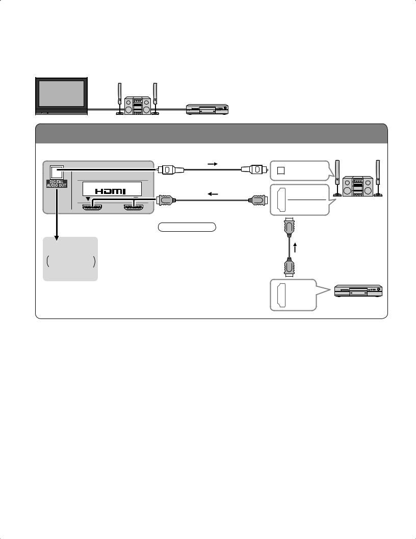
Basic Connection (Continued)
Example 4 |
Connecting Home Theater and DVD recorder |
TV |
Home Theater |
DVD Recorder
To connect HDMI terminals
Back of the TV
AV |
IN |
1 |
2 |
DIGITAL
AUDIO IN
HDMI
AV OUT
HDMI |
Home Theater |
|
AV IN |
||
(AV amp) |
||
|
Home theater
(DIGITAL AUDIO IN)
When listening to TV audio
[ATSC only]
Note
•It is recommended that you use Panasonic’s HDMI cable. (P.26)
•When Using the COMPONENT VIDEO OUT terminals or the
S VIDEO OUT terminal, refer to p.13 “To use COMPONENT terminals” or “To use S VIDEO terminals”.
•If you connect RAM theater or Player theater with HDMI cable, use audio cable instead of the optical digital audio cable. (see p.37)
HDMI
AV OUT
DVD Recorder
14
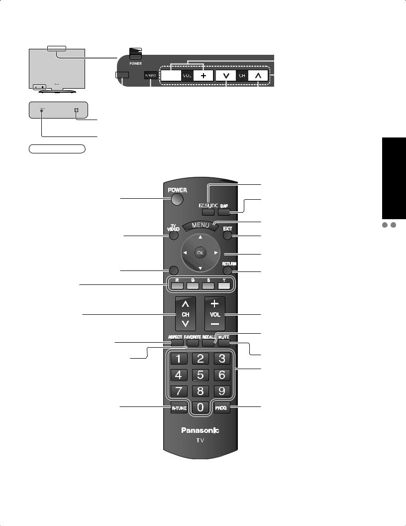
Identifying Controls
|
|
|
|
|
|
|
|
|
|
|
|
|
|
|
|
|
|
|
|
|
|
|
|
|
|
|
|
|
POWER button |
|
|
|
|
|
|
|
|
|
|
|
|
|
|
|
|
|
|
|
|
|
|
|
|
|
|
||||
|
|
|
|
|
|
|
|
|
|
|
|
|
|
|
|
|
|
|
|
|
|
|
|
|
|
|
|
|
|
|
|
|
|
|
|
|
|
|
|
|
|
|
|
|
|
|
|
|
|
|
|
|
|
|
|
|
|
|
Volume up/down |
|
|
|
|
|
|
|
|
|
|
|
|
DEMO |
|
|
|
|
|
|
|
|
|
|
|
|
|
Menu navigations |
|||
|
|
|
|
|
|
|
|
|
|
|
|
|
|
|
|
|
|
|
|
|
|
|
|
|
|||||
|
|
|
|
|
|
|
|
|
|
|
|
|
|
|
|
|
|
|
|
|
|
|
|||||||
|
|
|
|
|
|
|
|
|
|
|
|
|
|
|
|
|
|
|
|
|
|
|
|
|
|
|
|
|
Selects channels |
|
|
|
|
|
|
|
|
|
|
|
|
|
|
|
|
|
|
|
|
|
|
|
|
|
|
|
|
|
|
|
|
|
|
|
|
|
|
|
|
|
|
|
|
|
|
|
|
|
|
|
|
|
|
|
|
|
|
|
|
|
|
|
|
|
|
|
|
|
|
|
|
|
|
|
|
|
|
|
|
|
|
|
|
|
|
|
|
|
|
|
|
|
|
|
|
|
|
|
|
|
|
|
|
Switches TV/VIDEO |
|
|
|
|
|
|
|||||||||
|
|
|
|
|
|
|
|
|
|
|
|
|
|
|
|
|
|
|
|
|
|||||||||
|
|
|
|
|
|
|
|
|
|
|
|
|
|
|
|
|
|
in sequence |
|||||||||||
|
|
|
|
|
|
|
|
|
|
|
|
Demonstrates picture quality in vivid mode. |
|
|
|
||||||||||||||
|
|
|
|
|
|
|
|
|
|
|
|
|
|||||||||||||||||
|
|
|
|
|
|
|
|
|
|
|
|
(Press any key to cancel the demo.) |
|
|
|
|
|||||||||||||
|
|
|
|
|
|
|
|
|
|
|
|
|
|
|
|||||||||||||||
|
|
|
|
|
|
|
|
|
|
|
|
|
|
|
|||||||||||||||
|
|
|
|
|
|
|
|
|
|
|
Remote control sensor |
|
|
|
|
||||||||||||||
|
|
|
|
|
|
|
|
|
|
|
|
|
|
|
|||||||||||||||
|
|
|
|
|
|
|
|
|
|
|
Within about 23 feet (7 meters) in front of the TV set. |
|
|
|
|
||||||||||||||
|
|
|
|
|
|
|
|
|
|
|
Power indicator (on: red, off: no light) |
|
|
|
|
||||||||||||||
Note
•The TV consumes a limited amount of power as long as the power cord is inserted into the wall outlet.
Switches TV to On or Standby
Changes the input mode (p. 20)
EZ Sync menu (p. 21, 26-27)
Selects Audio Mode for TV viewing (p. 18)
Displays Main Menu (p. 22)
Exits menus
Selects/OK/Change
SUB
MENU
Displays Sub Menu (p. 18, 24) |
Returns to previous menu |
Colored buttons
(used for various functions) (for example p. 30)
Channel up/down
Changes aspect ratio (p. 19)
Operates the Favorite channel list function. (p. 19)
Volume up/down
Displays or removes the channel banner (p. 18)
Sound mute On/Off
Numeric keypad to select any channel (p. 18) or press to enter alphanumeric input in menus. (p. 20, 21, 28, 30)
Switches to previously viewed |
- |
Direct channel access for DTV and |
channel and input modes. |
|
DBS (p. 18) |
Start Quick
Controls Identifying Guide
Recorder) DVD + Theater Home + (TV Connection Basic
15
Loading...