

Panasonic sv-3200 Operating Instructions Manual
Panasonic
Digital Audio Tape Deck
SV-3200
OPERATING INSTRUCTIONS
.- -
,-:,':
.
-... • ..
..
..
.
..
.-{~
co:;,':
•
-
-~-
[
• • I
:;]
@
-
..
"
iii
'- '
Before connecting, operating or adjusting this product,
please read these instructions completely.
W
Pr
inted
in
Japan
RQT1871-P
Fl192K11
22
Thank you for purchasing the Digital Audio Tape Deck,
SV-3200.
For optimum performance and safety, please read these
instructions carefully.
Table
of
Contents
Precautions
.......
..
....
...
........................
3
Safety . .
....
....
. •
...
. . . .
......... . .•.....
. .
..
.•..
....
3
Installation
........•.......
.. . ..
....................
. 3
Maintenance
......••.
...•
..
.......
. .
............
. .
..
3
Service.....
....... . ...
..•. . ...
. .
...
..
. .
...
. .
.. .. ..
..
3
Preparation. . . . . . . . . . . . . . . . . . . . . . . . . . . . . . . . . . . . . . . . . . 4
Supplied
accessories
.... • .... . ......
..
. .
....•.......
4
Installation . .............
.....
.....
. .
....
............
4
Connections
....... . ..
..
.....
..
......
......
.........
5- 6
Front Panel
Controls
and
Functions.
. . .
....
......
7
Recording
.........
..............
.......... ......
.. .
24
To
make
analog
recordings.
. . . . . . . . . . . . . . . . . . . . . . . . . . .
24
How
to
make
silent
spaces
on
tape/how
to
erase
....
. .
..
25
To
adjust
recording
level
(for
analog
Inputs)
...... . .....
26
To
make
digital
recordings
..............
.....
....•....
27
Digital
recording
from
a CD
player.
. . . . . . . . . . . . . . . . . . .
..
28
To
make
fade
in/fade
out
recordings.
. . . . . . . . . . . . . . . . .
..
29
Indexing
.......
..
...................................
30
Recording
and
erasure
of
start
10/skip ID/end
mark.
. . .
..
30
To
record
start
10's
(during
playback)
......
. .
...
...
31
- 32
CAUTION
c
•
Control
section
....
..............
.........
.....
......
7- 9
Display
section
....
... . .. . ....
........... . .. . ....
....
10
Remote
control
section.
. . . . . . . . . . . . . . . . . . . . . . . . . . . . .
..
11
Basic Operating
Procedure
for
Recording
and
Playback..............
....
................
12-13
Counter
display.............
. . .
....... . ...
.......
14-15
Playback
...
....
.....................................
16
To
play
the
tape
from
the
beginning . ...
..
...... . .......
16
Playback
of
any
desired
tune
(Access
play)
....
.... . ...
17
To
skip
program
(Skip
play).
. . . . . . . . . . . . . . . . . . .
..
. . . . .. 18
To
playback
tunes
in
any
desired
order
(Program
play)
. . . . . . . . . . . . . . . . . . . . . . . .
..
. . . . . .
..
19-20
To
playa
tape
repeatedly
(Repeat
play)
...•.......
... ...
21
Before Recording
........
....
......................
22
To
record
absolute
time
.........
.............•...
•.
..
22
To
record
program
numbers
......................
.
.. . 23
The model number and serial number
01
this product c
an
be
found
on
either the back or the bottom
of
the unit.
Please note them
in
the space provided below and retain
them for future reference.
MODELNUMBER
__________
~S~V~-3~2~0~0
________
___
SERtAL NUMBER
________________
_________
CAUTION:
TO PREVENT ELECTRIC SHOCK MATCH
WIDE BLADE OF PLUG TO WIDE SLOT,
FULLY INSERT.
WARNING:
TO REDUCE THE RISK OF FIRE
OR
ELECTRIC SHOCK, DO NOT EXPOSE THIS
APPLIANCE TO RAIN
OR
MOISTURE.
To
assign
sequential
numbers
to
recorded
start 10's
(Renumber)
........ . .. . ...................
...... . ..
33
To
erase
start
10's
(during
playback)
. . . . . . . . . . . . . . . . .
..
34
To
record
or
to
erase
Skip
10's
(during
playback) . .....
..
35
To
record
or
to
erase
the
end
mark
. . . . . . . . . . . . . . . . • . .
..
36
Concerning
the Remote
Control
..................
37
Concerning
OAT
Cassette
Tape
..............
....
38
Operation
Notes..
. .. . .. .. .. .. .. . . .. .. .. .. . .. .. . . . ..
39
Technical
Information 1 ..... .....
. .
...
. .
...
..
......
40
SCMS (Serial
Copy
Management
System)
...
.......
40-41
Technical
Information
2............. ...............
42
MASH
type
1-bit
AOC/
DAC ...... .....
.................
42
Technical
Specifications
.....
......
.....
..........
43
Troubleshooting
Guide.
. . . . . . . . . . . . . . . . . . . . . . . . . .. 44
Index
.. ... ..
...................
....
................
..
45
CAUTION: TO REDUCE THE RISK OF ELECTRIC
SHOCK, DO NOT REMOVE SCREWS.
NO USER-SERVICEABLE PARTS
INSIDE.
REFER SERVICING TO QUALIFIED
SERVICE PERSONNEL.
A
The lightning flash with arrowhead symbol. within
an
equitateraltriangle, is intended to atert the user
to the presence of uninsutated "dangerous
voltage" within the product's enclosure that may
be of sufficient magnitude to constitute a risk of
etectric shock
to
persons.
The exctamation point within an equitateral
tr
io
angte is intended
to
atert the user
to
the presence
of important operating and maintenance (ser·
vicing) instructions
in
the titerature accompanying
the apptiance.
~
-2-
E
F
I
c
,
--
------
----
------
--
--------
--
------------
9
n
,r
s
y
)f
i-
e
Precautions
Before using this unit please read these operating instructions
carefully. Take special care
to
follow the warnings indicated on the
unit itself
as
well
as
the safety suggestions listed below.
Afterwards keep them handy for future reference .
Safety
1.
Power
Source --The unit should be connected
to
power supply
only
of
the type described
in
the operating instructions or as
marked on
the
unit.
2.
Polarization
--
If the unit
is
equipped with a potarized AC power
plug
(a
plug having one blade wider than the other), that plug will
fit into
the
AC
outlet only one way. This
is
a safety feature.
If
you
are unable
to
insert the plug fully into the outlet,
try
reversing the
plug
If the plug should still fail to
fit,
contact your electrician to
replace your obsolete oullet. Do not deleat the safety purpose of
the polarized plug.
Installation
Environment
1.
Water
and
Moisture --Do not use this unit near
water-for
example, near a bathtub, washbowl, swimming pool, or the like.
Damp basements should also be avoided.
2.
Condensation --Moisture may form on the head
in
the following
cases ...
- immediately after a heater has been turned on.
-
in
a steamy or very humid room .
-when
the unit
is
suddenty moved from a cold environment
to
a
warm one.
Placement------------
1.
Ventilation --The unit should be situated so that its location or
position does not interfere with its proper ventilation . Allow
10
cm
(4
") clearance from the rear of
the
unit.
2.
Foreign
Material --Care should be taken so that objects do not
fall into and liquids are not spilled into the unit. Do not subject this
unit
to
excessive smoke, dust, mechanical vibration, or shock.
3.
Magnetism --The unit should be situated away from equipment
or devices that generate strong magnetism.
4.
Stacking --Do not place heavy objects, other than system
components, on top of
the
unit.
1.
Damage
Requiring
Service --The unit should be serviced
by
qualified service personnel when:
(a) The
AC
power supply cord or the plug has been damaged; or
(b) Objects have fallen or liquid has been spilled into the unit; or
(c) The unit has been exposed to rain; or
CAUTION:
This equipment has been tested and found
to
comply with the
limits for a Class B digital device , pursuant
to
Part 15 of the FCC
Rules. These limits are designed
to
provide reasonable protec-
tion against harmful interference
in
a residential installation . This
equipment generates, uses and can radiate radio Irequency
energy and .
if
not installed and used
in
accordance with the
instructions, may cause harmful interference
to
radio com-
munications. However. there
is
no
guarantee that interference
will not occur
in
a particular installation. It this equipment does
cause harmlul interference
to
radio or tetevision reception, which
-3-
3.
Power
Cord
Protection --AC power supply cords should
be
routed so that they are not likely
to
be walked on or pinched
by
items ptaced upon or against them Never take hold of the plug or
cord
it
your hand is wet, and always grasp the plug body when
connecting or disconnecting
it.
4.
Nonuse
Periods --When the unit is not used, turn the power ott .
When left unused for a long period of time, the unit should be
unplugged from the household
AC
oullet.
If moisture forms inside this unit,
it
may not operate property. To
correct this problem, turn
on
the power and wait about one hour
for the moisture
to
evaporate.
3.
Heat --The unit should be situated away from heat sources such
as radiators and the like .
ft
also should not be placed
in
temperatures less than
5'C
(41
'F)
or greater than
35'C
(95'F).
5.
Surface --Place the unit
on
a flat, level surface.
6.
Carts
and
Stands
-- The unit should be used only with a cart or
stand that
is
recommended by the manufacturer. The unit and
cart combination should be moved with care.
{I
Quick stops, excessive force, and uneven
surfaces may cause the unit and cart combi·
nation to overturn .
7.
Wall
or
Ceiling
Mounting --The unit should not be mounted
to
a
wall or ceiling, unless specified
in
these operating instructions.
Maintenance----------------------------------
Ctean the cabinet, panel and controls with a soft cloth lighlly Do not use any type of abrasive pad, scouring powder or solvent
moistened with mild detergent solution.
such as alcohol or benzine.
Service
(d) The unit does not appear to operate normally or exhibits a
marked change
in
performance; or
(e) The unit has been dropped, or the enclosure damaged.
2.
ServiCing --The user should not attempt
to
service the unit
beyond that described
in
the operating instructions. All other
servicing should be referred to qualified service personnel.
can be determined by turning the equipment
011
and on. the user
is
encouraged
to
try to correct the interlerence by one
01
the
lollowing measures :
_Reorient or relocate the receiving antenna.
-Increase
the separation between the equipment and receiver.
-Connect
the equipment into
an
outlet
on
a circuit dille rent lrom
that to which the receiver
is
connected.
-Consult
the dealer or an experienced radiolTV technician lor
help.
Preparation
Supplied accessories
AC power supply co
rd
(polarized) .
1 pc.
Stereo connection cable
(SJP2249-4)
Balleries
AAA. 1.5 V (R03BPAJ2ST)
2pcs
.
Installation
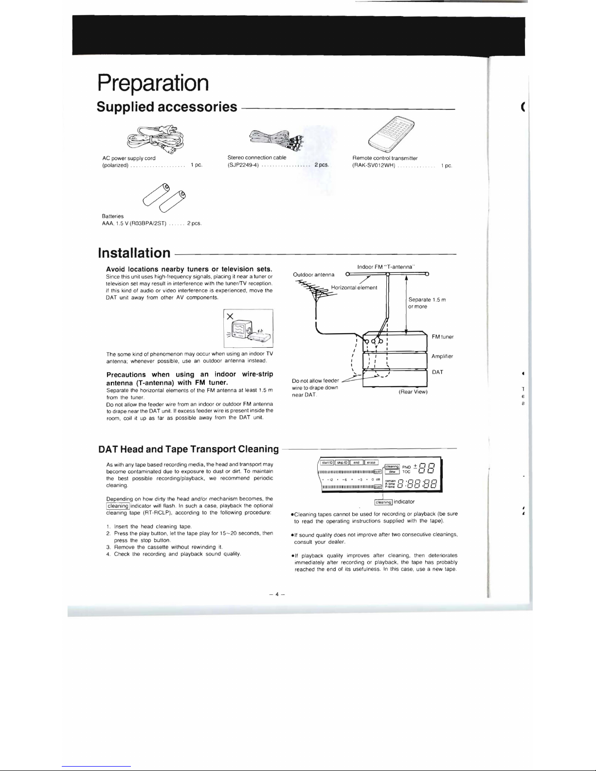
Avoid locations nearby tuners or television sets.
Since this unit uses high-frequency signals, placing it near a tuner or
television se t may result
in
interference with the tunerfTV reception.
If
this kind of audio or video interference is experienced, move the
OAT unit away (rom other
AV
components.
The some kind of phenomenon may occur when using an indoor
TV
antenna; whenever possible, use
an
outdoor antenna instead.
Precautions when using
an
indoor wire-strip
antenna (T-antenna) with
FM
tuner.
Separate the horizontal elements of the FM antenna
at
least 1.5 m
from the tuner.
Do
not allow the feeder wire from
an
indoor or outdoor FM antenna
to
drape near the OAT unit.
If
excess feeder wire is present inside the
room, coil
it
up as far as possible away from the OAT unit.
DA T Head and Tape Transport Cleaning
As with any tape based recording media, the head and transport may
become contaminated due to exposure
to
dust or dirt. To maintain
the best possible recording/playback, we recommend periodic
cteaning.
Depending
on
how dirty the head and/or mechanism becomes . the
Icleaning
!i
ndicator will flash. In such a case, playback the optional
cleaning tape (RT-RCLP), according to the following procedure:
1.
Insert the head cleaning tape.
2.
Press the play bullon, lei the tape play
for' 5-20
seconds. then
press the stop bullon .
3. Remove the casselle without rewinding i
t.
4. Check Ihe recording and playback sound quality.
-4-
(
Remole conlrol transmiller
2 pcs.
(RAK-SVOI2WH) .
1 pc.
Indoor FM " T-antenna"
Separate 1.5 m
or more
Do
not allow feeder
FM tuner
Amplifier
OAT
wire to drape down
(Rear View)
near
OAT.
€
a
eCleaning tapes cannot be used for recording or playback (be sure
10
read the operating instructions supplied with the tape).
elf
sound quality does not improve after two consecutive cleanings,
consult your dealer.
e
lf
playback quatity improves after cleaning . then deteriorates
immediately after recording or playback. the tape has probably
reached the end
of
its usefulness.
In
this case, use a new tape.
1
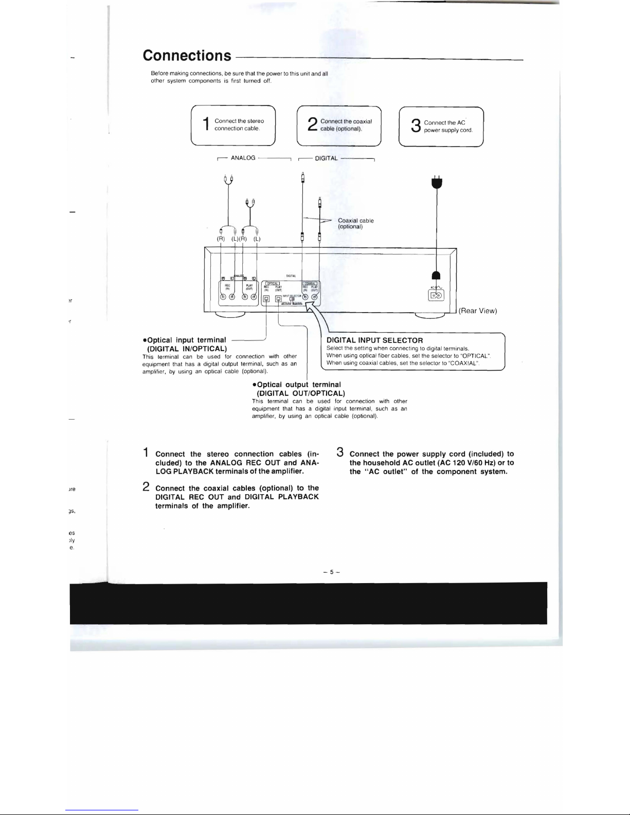
Connections
Before making connections, be sure that the power
to this unit and all
other sys tem components is first turned off.
1
Connect the stereo
2
Connect the coaxial
3
Connect the
AC
connection cable.
cable (optional).
power supp
ly
cord .
r-
ANALOG -
---.,
.--
DIGITAL -----,
eOptical output terminal
(DIGITAL OUT/OPTICAL)
This terminal can be used for co nnection with other
equipment that has a digital input terminal, such as an
amplifier, by using an op
ti
cal cable (optional).
A
(R) (L)(R) (L)
~.------r--~r-+-----~~----------
________
~
r-
____
~~(RearView)
·r
eOptical input terminal
(DIGITAL IN/OPTICAL)
This terminal can be used for connection with other
equipment
th
at has a digital output terminal, such as an
amplifier, by using an optical cable (optional).
1 Connect the stereo connection cables (in-
cluded)
to
the ANALOG REC OUT and ANA-
LOG PLAYBACK terminals of the amplifier.
Jre
2 Connect the coaxial cables (optional) to the
DIGITAL REC OUT and DIGITAL PLAYBACK
terminals
of
the amplifier .
~
s,
es
lly
Coaxiat cable
(optiona
l)
DIGITAL INPUT SELECTOR
Select the setting when connecting
to
digital term inals.
When using optical fiber cables, set the selector to "OPTICAL
".
When using coaxial cables, set the selector
to
"COAXIAL
".
3 Connect the power supply cord (included) to
the household AC outlet (AC 120 V/60
Hz) or to
the
HAC
outlet" of the component system.

Preparation
(continued)
Connections (continued)
-------------------
About Optical Fiber Cables
To connect optical fiber cables
(t ) Remove the dust cap
(2) Connect the cable
from Ihe terminal.
Align the terminal shape .
Precautions when using
Do not attempt to bend optical fiber cables
at
severe ang le
s.
Be sure that connections are made securely .
Store the dust cap securely . and replace
it
whenever cables are not
connected
to
the terminals. If dust
is all
owed
to
enter the terminal
connector. signal errors may result.
About OPTICAL connector
When the optical connectors are used. electrical signals are
converted into light signals
for
transmission between units. making
the Signals impervious
to
adverse effects from external noise. This
form of connection thus allows the highest quality
of
digital audio
signal transmission.
this unit's DIGITAL
OUT
connection
--
-
----
- -
---
- - - -
If
this unit
is
connected incorrectly to your stereo amplifier, a
re
cording feedback loop may occur due
to
the
OAT
unit's output is
fed
back into the
OAT
unit for recording, resulting
in
and possible
damage
to
your speakers . Be sure to abide
by
the following
precautions :
1)
When using the unit's DIGITAL tN/
OUT
terminals for recording or
playback,
be
sure
to
connect only to your amplifier's DIGITAL
REC OUT (OUTPUT) and DIGITAL PLAYBACK (INPUT) terminals.
-6
-
2) If your amplifier has no DIGITAL PLAYBACK or DIGITAL REC
OUT terminals, and you make your connections
to
the amplifier's
conventional DIGITAL INPUT terminals for playback, be sure to
use this unit (OAT recorder) for playback only (not for recording) .
3)
If your unit is used for recording when connected as described
in
step 2 above, do not set the OAT unit's INPUT SELECTOR
to
the
DIGITAL position .
(
I
Front
Panel
Controls
and
Functions
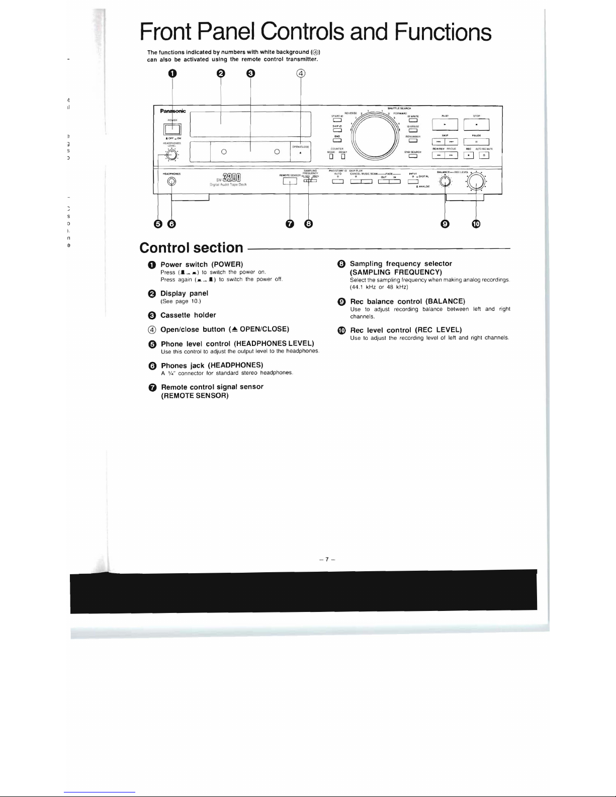
The functions Indicated
by
numbers with white background (@)
can also
be
activated using the remote control transmitter.
o
4
·0'·.·
..
7 = ' '
~':'"
~.::
~,
00
:
S~ ~
\0
[)II"
"
I
10
[:::J
[:::J
~
NO
ItDtIIJMMIl
[:::J
[:::J
I - I - I I I
~(W'AL'V
"
oCuI
Rf.C
.IJJ"'O":.w"
"""'''''
De
i'
lItDO CI'I
1- 1
00
1
D~
l"i'iii,'iii01&0'
10
~~
y
4IIr
o
C.
~IU.
"".UC
SC
"I'I
_,,,,O£
_
IHP
ur
o
ur
iii
0 _
omr
UL
c:::J c::::r::::J c::::r::::J
c:::::J
s
o
n
e
Control section
o Power switch (POWER)
Press
(I_a)
to
switch the power on.
Press again
(a
_
I)
to
switch the power off.
e Display panel
(See page 10.)
€) Cassette holder
@)
Open/close button
(~OPEN/CLOSE)
o Phone level control (HEADPHONES LEVEL)
Use this control
to
adjust the oulput level to the headphones
o Phones jack (HEADPHONES)
A
'/4"
connector for standard stereo headphones.
o Remote control signal sensor
(REMOTE SENSOR)
Q Sampling frequency selector
(SAMPLING FREQUENCY)
Selectlhe
sampling frequency when making analog recordings .
(44.1 kHz or 48 kHz)
o Rec balance control (BALANCE)
Use
to
adjust recording balance between left and right
channels.
~
Rec level control (REC LEVEL)
Use
to
adjust the recording level of left and right channels.
Front
Panel
Controls
and
Functions
(continued)
D
HEADPHOMi:Ii
lrvu
·0····
. .
14 15
16
o
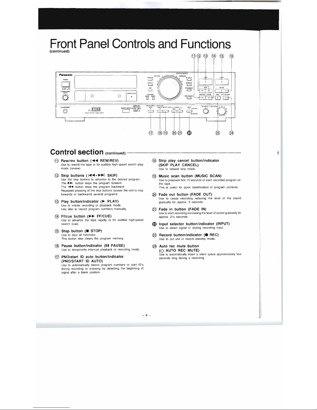
Control section (continued)
-----------------
@ Rew/rev button
(~~
REW/REV)
Use
to
rewind the tape or for audible high·speed search play
mode (review).
@ Skip buttons (
I<III~
•
~~
SKIP)
Use the skip buttons to advance
to
the desired program.
The
~~
button skips the program lorward
The
I<0Il
..
button skips the program backward
Repeated pressing
01
the skip buttons causes the unit
to
skip
forwards or backwards several programs.
@ Play button/indicator
(~
PLAY)
Use
to
initiate recording or ptayback mode.
Use also
to
record program numbers manually .
® Ff/cue button
(~~
FF/CUE)
Use to advance the tape rapidly or for audible high·speed
search (cue).
@)
Stop button
(_
STOP)
Use to stop all functions.
This button also clears the program memory.
@ Pause button/indicator (II PAUSE)
Use
to
temporarily interrupt playback or recording mode.
@ PNO/start
10
auto button/indicator
(PNO/ST ART
10
AUTO)
Use
to
automatically record program numbers or start 10's
during recording or indexing
by
detecting the beginning of
signal after a blank position.
-8-
@ Skip play cancel button/indicator
(SKIP PLAY CANCEL)
Use
to
release skip mode.
@)
Music scan button (MUSIC SCAN)
Use
to
playback first
15
seconds
01
each recorded program on
the tape.
This is uselul for
Quick
identification
01
program contents.
® Fade out button (FADE OUT)
Use
to
cease recording reducing the level
01
the sound
gradually lor approx. 5 seconds.
~
Fade
in
button (FADE IN)
Use to start recording increasing the level
01
sound gradually for
approx.
2'12
second
s.
ED
Input selector button/indicator (INPUT)
Use
to
select digital or analog recording input.
@ Record button/indicator
(e
REC)
Use
to
put unit
in
record standby mode.
@ Auto rec mute button
(0
AUTO
REC
MUTE)
Use to automatically insert a silent space approximately four
seconds long during a recording.
5 6
9
30
31
Panasonic
~----,I
1
,--------,
I
-I
-I
o
1-1-108
3
33
34
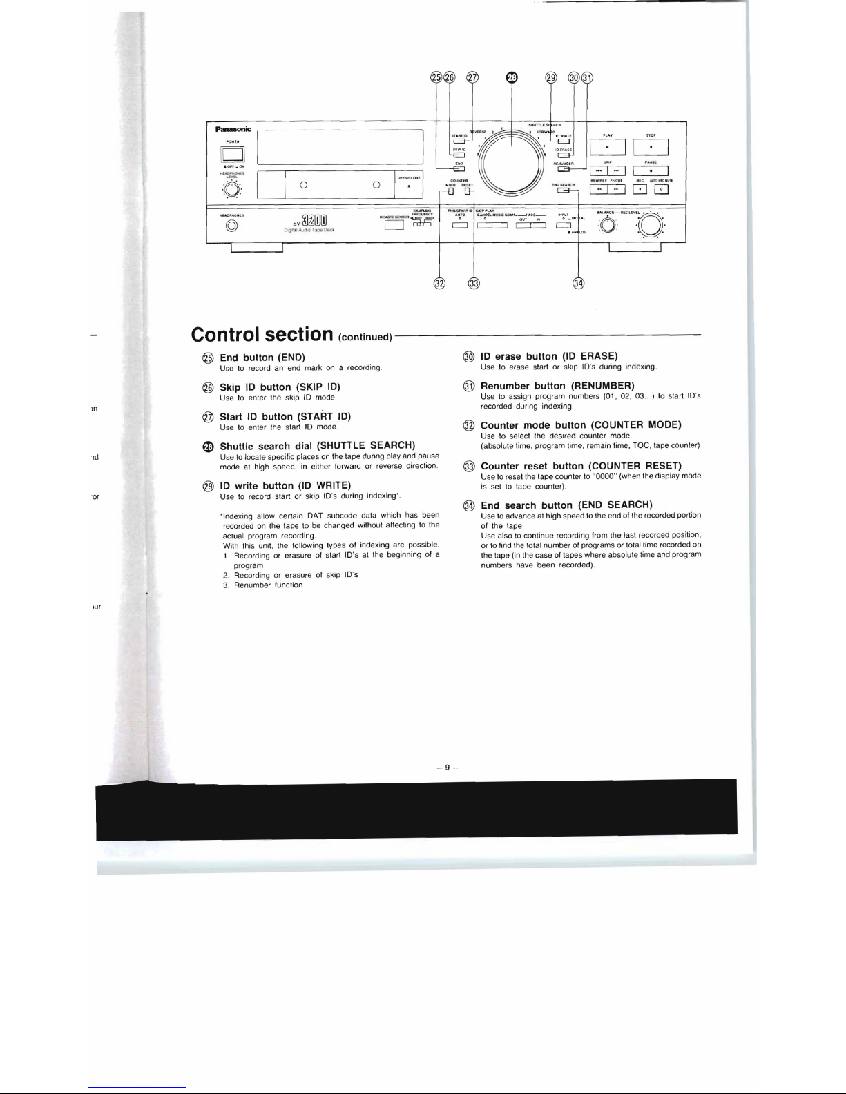
Control section
(continued)-----------------
@
End
button (END)
Use to record an end mark on a recording .
@ Skip
10
button (SKIP
10)
Use
to
enter the skip
10
mode.
m
® Start
10
button (START
10)
Use to enter the start
10
mode.
fD
Shuttle search dial (SHUTILE SEARCH)
ld
Use
to
locate specific places
on
the tape during play and pause
mode
at
high speed,
in
either lorward or reverse direction
@
10
write button
(10
WRITE)
'
or
Use
to
record start or skip ID's during indexing'.
'Indexing allow certain
OAT subcode data which has been
recorded on the tape to
be
changed without alfecting
to
the
actual program recording.
With this unit, the following types
of
indexing
are
possible.
1. Recording
or
erasure of start ID's at the beginning of a
program
2. Recording or erasure
01
skip ID's
3. Renumber function
lur
-9-
@ ID erase button
(10
ERASE)
Use to erase start or skip ID's during indexing .
® Renumber button (RENUMBER)
Use to assign program numbers (01, 02, 03 ..)
to
start ID's
recorded during indexing.
® Counter mode button (COUNTER MODE)
Use to select the desired counter mode .
(absolute time, program time, remain time,
TOe,
tape counter)
@ Counter reset button (COUNTER RESET)
Use
to
reset the tape counter to "0000" (when the display mode
is set
to
tape counter) .
® End search button (END SEARCH)
Use
to
advance
at
high speed to the end of the recorded portion
of the tape.
Use also
to
continue recording from the
tast
recorded
pOSition,
or to lind the total number of programs or total time recorded on
the tape
(in
the case of tapes where absolule time and program
numbers have been recorded).
Front
Panel
Controls
and
Functions
(continued)
IIJIIIIIIIIIIIIIIIIIIIIIIIIIIIIIIIIIIIIIIIIIIIIIIIIIIIIIIIIIIIIIIIIIII11111111
cleaning
dew
P 0 +
1111
Toe
- I I I I
-60
-50
-40
-30 • -24
• - 18 •
-12 • -6
-3
• 0
dB
remain "
,"
"
.,-,
"
A-lime - - -
--
[£jJlllllllllllllllllllllllllllllllllllllllllllllllllllllllllllllllllllllllllll
love
ri
P-time
LI .LI
LI
'LI
LI
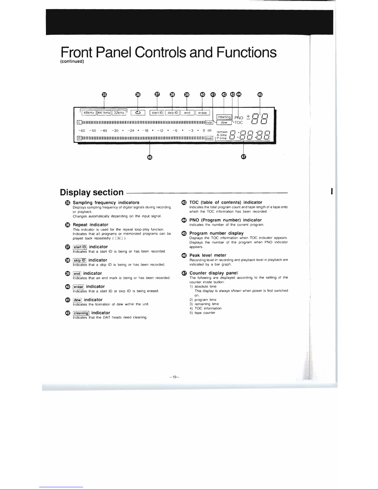
Display section
~
Sampling frequency indicators
e TOC (table of contents) indicator
Displays sampling frequency
of
digital signals during recording
Indicates the total program count and tape leng
th
of
a tape onto
or playback.
which the TOC information has been recorded
Changes automatically depending on the input signal.
<D
PNO (Program number) indicator
~
Repeat indicator
Indica tes the number of the current program.
This indicator is used for the repeat loop- play function .
fndicafes that all programs or memorized programs can be
~
Program number display
played back repeatedly (
@:J
).
Displays
the
TOC information when TOC indicator appears.
Di
splays the number of the program when PNO indicator
ED
I
slartlO
1 indicator
appears.
Indi
ca
tes that a start
lOis
being or has been recorded.
~
Peak level meter
ED
I
sklp
10
1 indicator
Recording level in recording and playback level
in
playback are
Indicates that a skip
10
is
being or has been recorded.
indicated by a bar graph.
ED
lend l indicator
(D Counter display panel
Indicates that an end mark
is
being or has been recorded .
The following are displayed according
to
the selling
of
the
counter mode bullon:
~
lerase l indicator
1)
absolute time
Indicates that a sfart
10
or skip
10
is
being erased.
This display
is
always shown when power
is
first switched
on.
CD
Idewl indicator
Indicates the formation of dew within the unit.
(D
Icleaningl indicator
Indicates that the OAT heads need cleaning .
2)
program time
3)
remaining time
4) TOC information
5)
tape counter
-
10-
I
-
~
48
__"...
..
-lolt
·U
O·
~·
DO
&
;-,
'
~,-:-
16
0
00
0'
49
116
Lo_
1616
6
"<:::;:'
115
50
00
"0 "
J
E:J
DODD
51
,oJ
...
..
.... ..
,
un
o DCJC:J 0
o
O"[jE)t5'
OC=J
~
-"
r",' Dtt:J<
DI'IT
Panasonic
'-
.-/
Ito
rs
.
tor
Ire
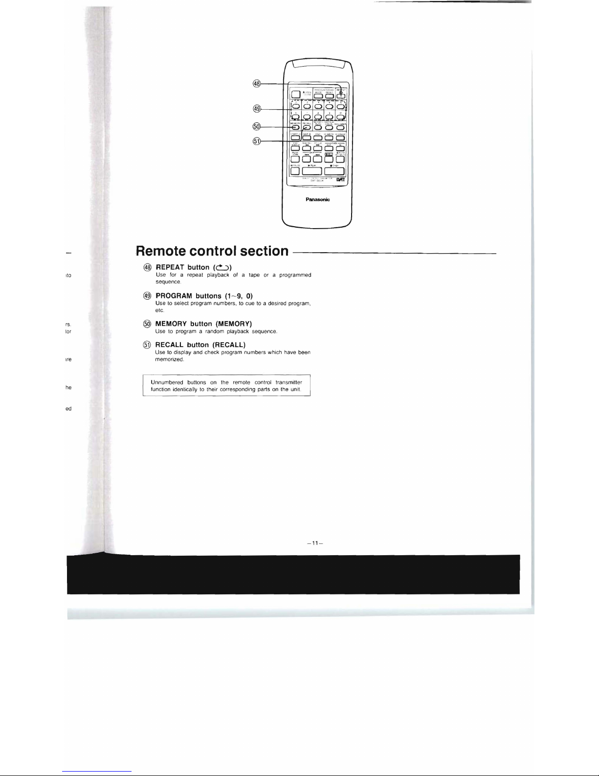
Remote control section
@ REPEAT
button
(~)
Use for a repeat playback
of
a tape or a programmed
sequence.
@ PROGRAM
buttons
(1-9,
0)
Use
to
select program numbers,
to
cue
to
a desired program,
etc.
® MEMORY
button
(MEMORY)
Use to program a random playback sequence.
® RECALL
button
(RECALL)
Use to display and check program numbers which have been
memorized.
Unnumbered buttons on the remote control transmitter
he
function identically to their corresponding parts on the unit.
ed
---------
-
----
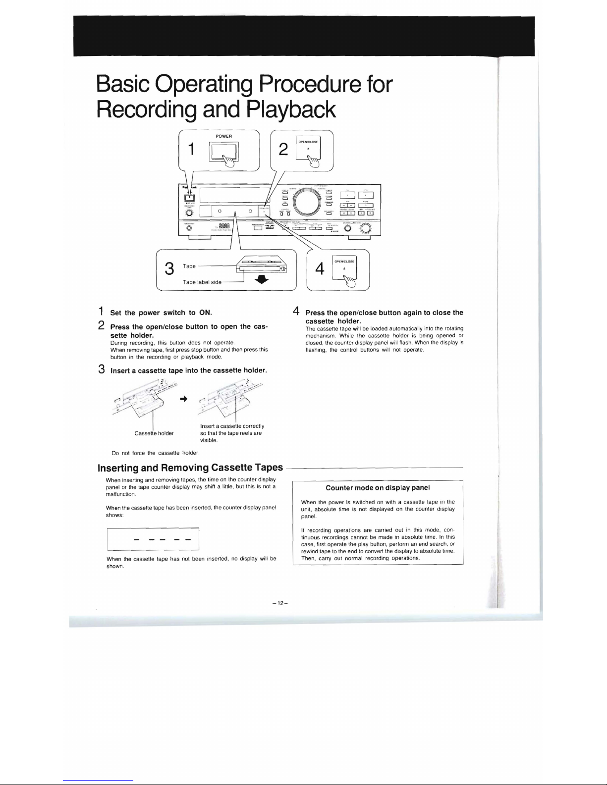
Basic
Operating
Procedure
for
Recording
and
Playback
POWER
1
..
2
O
PfWCLO
SE
4
DO
cTI
c:::i::::l
1--\:'"
10 -8 '
a
-'
·0 -
--:fiO" ' .
.
......
~
OPEH.'ClOSf
1 Set the power switch
to
ON.
2 Press the open/close button
to
open the cas-
sette holder.
During recording, this button does not operate.
When removing tape, first press stop button and then press this
button in the recording or ptayback mode.
3 Insert a cassette tape into the cassette holder .
Cassette holder
Do not force the cassette holder.
.--"
Insert a cassette correctly
so that the tape reels are
visible.
Inserting and Removing Cassette Tapes -
When inserting and removing tapes, the time on the counter display
panel or the tape counter display may shift a little. but this
is
not a
malfunction.
When the cassette tape has been inserted , the counter display panel
shows:
When the cassette tape has not been inserted, no display will be
shown.
-12-
4 Press the open/close button again
to
close the
cassette holder.
The cassette tape will be loaded automatically into the rotating
mechanism. White the cassette holder is being opened or
closed, the counter display panel will flash. When the display
is
flashing, the control buttons will not operate .
Counter mode on display panel
When the power is switched on with a cassette tape in the
unit. absolute time
is
not displayed on the counter displ
ay
panel.
If recording operalions are carried out
in
this mode, con-
tinuous recordings cannot be made in absolute time .
tn
this
case, first operate the play button, pertorm an end search, or
rewind tape to the end
to
convert the display to absolute time .
Then, carry out normal recording operations.
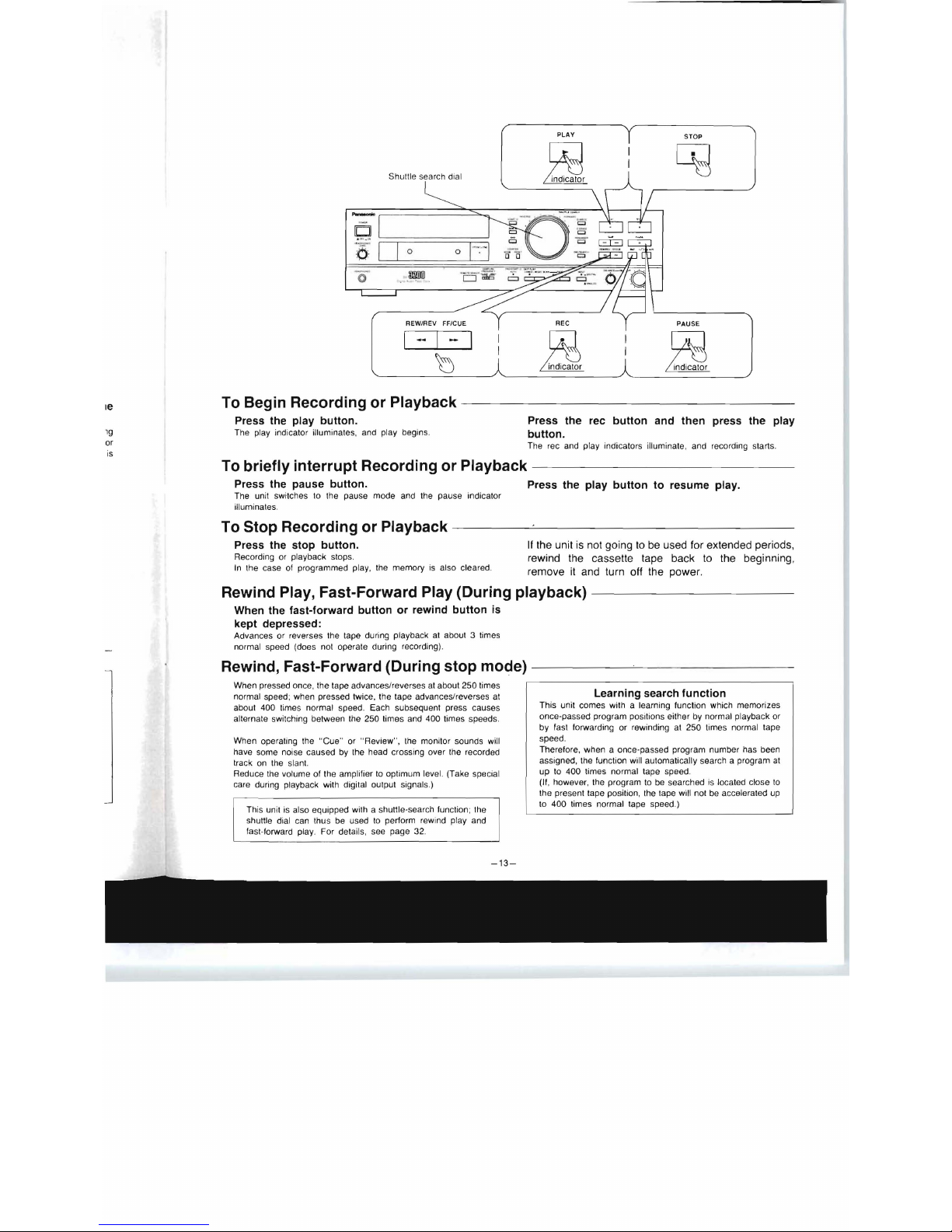
PLAY
STOP
Shultle search dial
-
o
o
REW/REV FF/CUE REC
PAUSE
I - I
To Begin Recording or Playback
--
----------------
Ie
Press the play button. Press the rec button and then press the play
19
The play indicalor illuminales , and play begins.
button.
or
The rec and play indicators illuminate, and recording starts.
is
To briefly interrupt Recording or Playback
--------------
Press the pause button.
Press the play button to resume play.
The unit switches to the pause mode and the pause indicalor
illuminates.
To Stop Recording or Playback
-
---~------------
Press the stop button.
If
the unit
is
not going
to
be
used for extended periods,
Recording or playback stops.
rewind the cassette tape back
to
the beginning,
In the case of programmed play, the memory
is
also cleared.
remove it and turn off the power.
Rewind Play, Fast-Forward Play (During playback)
----------
When the fast-forward button or rewind button
is
kept depressed:
Advances or reverses the tape during playback at about 3 times
normal speed (does not operate during recording).
Rewind, Fast-Forward (During stop mode)
-----
--'--
- -
-----
When pressed once, the tape advances/reverses at about 250 times
normal speed ; when pressed twice, the tape advances/reverses at
about 400 times normal speed. Each subsequent press causes
alternate switching between the 250 times and 400 times speeds.
When operating the "Cue" or " Review", the monitor sounds will
have some noise caused by the head crossing over the recorded
Irack on the slant.
Reduce Ihe volume of the amplifier
10
optimum level. (Take special
care during playback with digital output signals.)
This unit is also equipped with a shuttle-search function ; the
shuttle dial can thu s be used
10
perform rewind play and
fast-forward play. For details, see page
32
.
-13-
Learning search function
This unit comes with a learning function which memorizes
once-passed program positions either by normal playback or
by fast forwarding
or
rewinding at 250 times normal tape
speed.
Therefore, when a once-passed program number has been
assigned, the function will automatically search a program at
up
to 400 times normal tape speed.
(If, however, the program to be searched
is
located close
to
the present tape position, the tape will not be accelerated up
to 400 times normat tape speed.)
--
Basic
Operating
Procedure
for
Recording
and
Playback
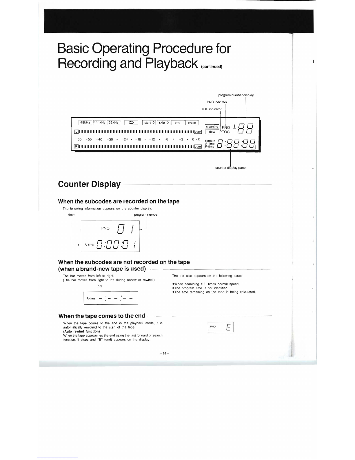
(continued)
program number display
PNO indicator
Toe
indicator
ict:a
e
:
g
i
TPO/\/OC
±
,I
,1/1
"
IIJIIIIIIIIIIIIIIIIIIIIIIIIIIIIIIIIIIIIIIIIIIIIIIIIIIIIIIIIIIIIIIIIIIIIIIIIIII~
. .
-
60
-50 -40
-30 • -24 • -18 • -12
• - 6 • - 3 • 0
dB
remain
/1
'/1
/1
'/1
/1
A-time - - -
--
[[]IIIIIIIIIIIIIIIIIIIIIIIIIIIIIIIIIIIIIIIIIIIIIIIIIIIIIIIIIIIIIIIIIIIIIIIIIII~
IP-time U .
LI
L/
·LI
LII
counter display panel
Counter Display
When the
subcodes
are recorded on the tape
The following information appears
on
the counter display.
time
program number
PNO
1/
/
~
LI
I
II
'/1/1
'/1
I
A-time L/ .
LI
LI
·LI
I
When
the
subcodes
are
not
recorded on the tape
(when a brand-new tape is used) -
---
-
----
- - -
----
- -
The bar moves from left to right.
The bar also appears
on
the following cases:
(The bar moves from right
to
left during review or rewind.)
-When
searching
400
times normal speed.
bar
-The
program time is not identified.
-The
time remaining
on
the tape is being calculated.
I
Mmo
i : --: -- '
When
the
tape
comes
to
the
end
----------
- - -
--
-
--
When the tape comes
to
the end
in
the playback mode,
it
is
,-
automatically rewound to the start of the tape.
PNO
e
(Auto
rewind
function)
When the tape approaches the end using the fast forward or search
function,
it
stops and " E" (end) appears
on
the display.
-14-
 Loading...