

Panasonic SD XC WV-SFN480 Installation Manual
4
3
2
1
Powered speaker Adjustment monitor
*
*
PoE device (hub)
PC
Adjustment monitor
Microphone
Powered speaker
Microphone
LAN cable
(category 5 or better, straight)
LAN cable
(category 5 or better, straight)
* Can switch to monitor out
(select the [Setup]→[Basic] tab, and then select [Monitor out])
LAN cable (category 5
or better, straight)
Panasonic System Networks Co., Ltd. 2014
Standard accessories
IMPORTANT:
● When the camera is initialized, the settings including the network settings will be initial-
ized. Note that the CRT key (SSL encryption key) used for the HTTPS protocol will not
be initialized.
Before initializing the settings, it is recommended to write down the settings in advance. ●
Do not turn off the power of the camera during the process of initialization. Otherwise, it ●
may fail to initialize and may cause malfunction.
Note:
The ACT indicator, Link indicator, SD ERROR/ABF indicator, and SD MOUNT indicator ●
inside the SD memory card slot cover can be turned off. (Indicators are set to light or blink
in the default settings.)
Turn off the indicators as required according to the installation environment. (☞ Operating
Instructions (included in the CD-ROM))
Note:
Since the connector storage section ●
does not have a sufficient space, use
a LAN cable that does not exceed the
sizes described in the illustrations.
IMPORTANT:
Use all 4 pairs (8 pins) of the LAN cable ● (category 5 or better, straight, STP).
The maximum cable length is 100 m {328 feet}. ●
Make sure that the PoE device in use is compliant with IEEE802.3af standard. ●
When connecting both the 12 V DC power supply and the PoE device for power ●
supply, 12 V DC will be used for power supply.*
If a 12 V DC power supply and a PoE hub or router are used at the same time, *
network connections may not be possible. In this case, disable the PoE settings.
Refer to the operating instructions of the PoE hub or router in use.
Depending on the PoE device used, if you stop the 12 V DC power supply after *
operating it and a PoE hub or router at the same time, the power supply may stop,
causing the camera to restart.
When the LAN cable is disconnected once, reconnect the cable after around ●
2 seconds. When the cable is quickly reconnected, the power may not be supplied
from the PoE device.
IMPORTANT:
Use 12 V DC power supply that is insulated from the commercial AC power. ●
Be sure to use the ●
D
power cord plug (accessory) provided with this product.
Be sure to fully insert the ●
D
power cord plug (accessory) into the 12 V DC power
supply terminal. Otherwise, it may damage the camera or cause malfunction.
When installing the camera, make sure that excessive force is not applied to the ●
power cable.
Be sure to use an AC adaptor compliant with the specifications (written in the indi- ●
cation label on the bottom side of this unit) regarding power source and power consumption.
Caution:
A READILY ACCESSIBLE DISCONNECT DEVICE SHALL BE INCORPORATED ●
TO THE EQUIPMENT POWERED BY 12 V DC POWER SUPPLY.
ONLY CONNECT 12 V DC CLASS 2 POWER SUPPLY (UL 1310/CSA 223) or ●
LIMITED POWER SOURCE (IEC/EN/UL/CSA 60950-1).
Note:
Fully insert the stripped cable core into the ●
D
power cable plug (accessory), and
check that the cable core of the wiring is not protruding out and shorting with the
adjacent terminal.
When connecting an external power supply to the camera, use the AWG 16 - AWG 24 ●
single-wired or stranded wired cables.
IMPORTANT:
The adjustment monitor is used for checking the adjustment of the angular field of ●
view when installing the camera or when servicing. It is not provided for recording/
monitoring use.
Depending on the monitor, some characters (camera title, preset ID, etc.) may not ●
be displayed on the screen.
Use a switching hub or a router which is compliant with 10BASE-T/100BASE-TX. ●
If a PoE hub is not used, each network camera must be connected to a 12 V DC ●
power supply.
When using 12 V DC, power supply from a PoE hub or router is not required. ●
IMPORTANT:
Be sure to use the ●
E
external I/O terminal plug (accessory) provided with this product.
Do not connect 2 wires or more directly to a terminal. When it is necessary to con- ●
nect 2 or more wires, use a splitter.
Install external devices so that they do not exceed the rating of the network camera. ●
When using the external I/O terminals as the output terminals, ensure they do not ●
cause signal collision with external signals.
Note:
Fully insert the stripped cable core into the ●
E
external I/O terminal plug (accessory),
and check that the cable core of the wiring is not protruding out and shorting with the
adjacent terminal.
4
3
2
1
ALARM IN3, AUX OUT
(Alarm input 3, AUX output)
GND
ALARM IN1
(Alarm input 1)
ALARM IN2, ALARM OUT
(Alarm input 2, Alarm output)
E External I/O terminal plug (accessory)
button
IMPORTANT:
Connect/disconnect the audio cables and turn on the power of the camera after turning ●
off the power of the audio output devices. Otherwise, loud noise may be heard from
the speaker.
Make sure that the stereo mini plug is connected to this cable. When a monaural mini ●
plug is connected, audio may not be heard.
When connecting a monaural speaker with amplifier, use a locally procured conversion
cable (mono-stereo).
Note:
Audio out is selected for the audio/monitor output plug by default. The plug can be ●
used for monitor out by selecting the [Setup]→[Basic] tab, and then selecting [Monitor
out]. (The ø3.5 mm monaural mini plug⇔RCA pin jack conversion cable is locally procured.)
Note:
Off, input, and output of the external I/O terminal 2 and 3 can be switched by con- ●
figuring the setting. Refer to the Operating Instructions on the provided CD-ROM
for further information about the external I/O terminal 2 and 3 (ALARM IN2, 3) settings (“Off”, “Alarm input”, “Alarm output” or “AUX output”).
Making connections
Connect the power cable
Installation Guide
Included Installation Instructions
Network Camera
Model No. WV-SFN480
Important Information ...............................1 pc.
Installation Guide (this document) ............1 set
CD-ROM*
Code label*
1
................................................ 1 pc.
2
.............................................. 1 pc.
Warranty card ...........................................1 set
*1 The CD-ROM contains the operating instructions and different kinds of tool software programs.
*2 This label may be required for network management. The network administrator shall retain the
code label.
The following parts are used during installation procedures.
A Attachment plate .................................. 1 pc.
B Bit (Hex wrench, screw size
6.35 mm {1/4 inches} T10) .................... 1 pc.
C Template A
.........................................
1 sheet
D Power cord plug ................................... 1 pc.
E External I/O terminal plug ....................1 pc.
F Audio cable .......................................... 1 pc.
G Cable tie ............................................. 2 pcs.
H Safety wire lug .....................................1 pc.
I Wire lug fixing screws
(M2.5 x 8 mm {5/16 inches}) .............. 2 pcs.
(incl. 1 spare)
J Desktop cover ...................................... 1 pc.
K Safety wire ........................................... 1 pc.
L Washer ................................................. 1 pc.
M Spring washer ...................................... 1 pc.
(incl. 1 spare)
B D
E F
Before making connections, prepare the required peripheral devices and cables, and turn off
each system's power supply.
Straight section
30 mm {1-3/16 inches}
40 mm {1-9/16 inches}
Example of LAN cable connector
9 mm
{11/32 inches}
13 mm {1/2 inches}
Connect a LAN cable
Connect the output cable to the D power cable plug (accessory).
q Loosen the screw of the power cable plug and strip 3 mm to 7 mm {1/8 inches to
9/32 inches} of the outer jacket. Expose the cable core (sufficiently twist any strand wires)
and then insert the cable into the power cable plug.
w Tighten the screw of the power cable plug. (Recommended tightening torque: 0.34 N·m
{0.25 lbf·ft})
This manual describes the installation procedures, network camera installation, cable connections, ●
and the angle of view adjustment.
Before reading this manual, be sure to read the Important Information. ●
For U.S. and Canada:
Panasonic System Communications
Company of North America,
For Europe and other countries:
Panasonic Corporation
http://panasonic.net
Unit of Panasonic Corporation
of North America
www.panasonic.com/business/
For customer support, call 1.800.528.6747
Two Riverfront Plaza, Newark, NJ 07102-5490
Panasonic Canada Inc.
5770 Ambler Drive, Mississauga,
Ontario, L4W 2T3 Canada
(905)624-5010
www.panasonic.ca
Panasonic System Networks Co., Ltd.
Fukuoka, Japan
Authorised Representative in EU:
Panasonic Testing Centre
Panasonic Marketing Europe GmbH
Winsbergring 15, 22525 Hamburg, Germany
PGQX1666YA Cs1114-1124 Printed in China
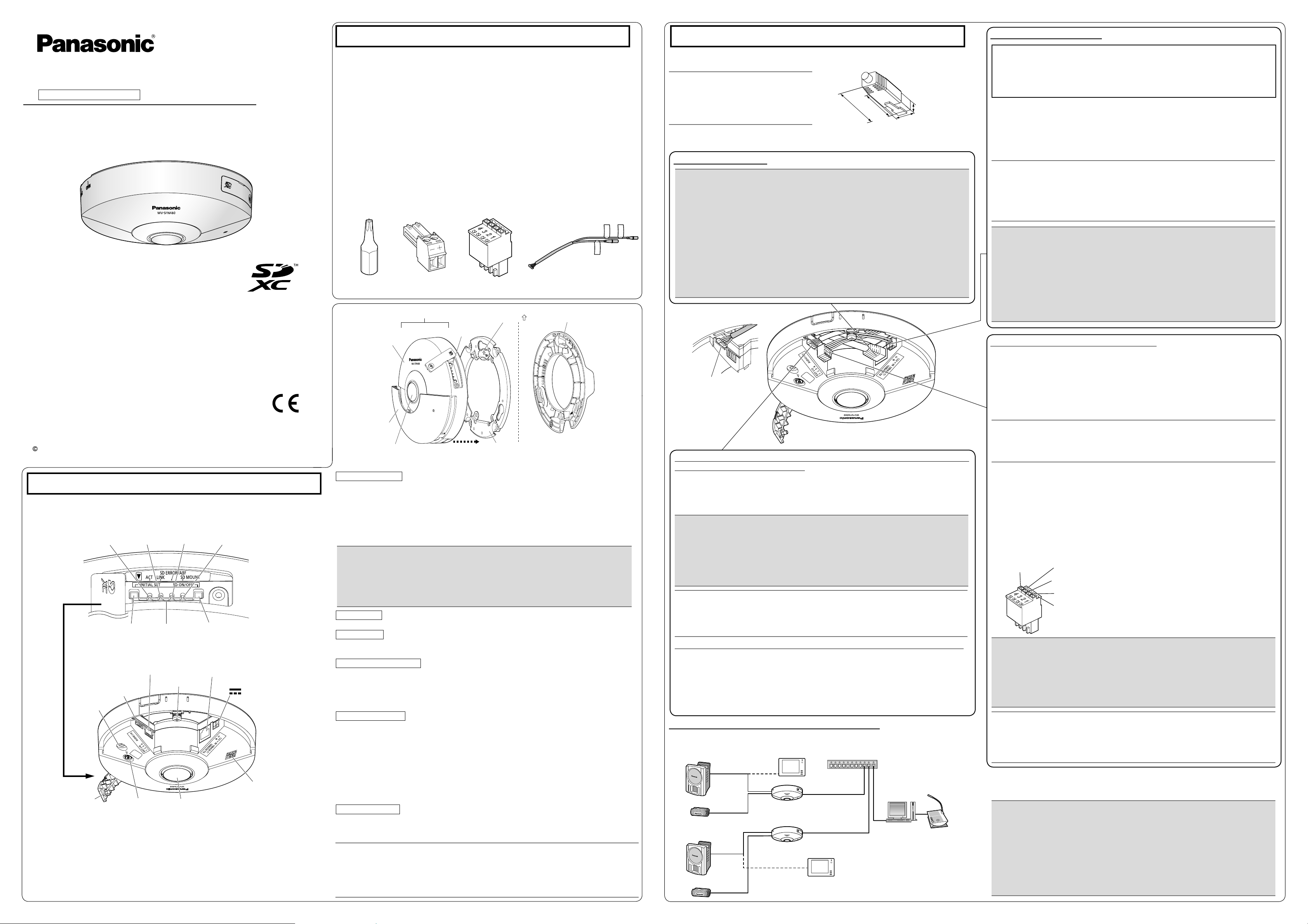
Major operating controls
The component names of the camera are as follows. Refer to the illustration when installing or
adjusting the camera.
<Inside view of the SD memory card slot cover (with SD memory card slot cover opened)>
ACT
indicator
LINK
indicator
SD ERROR/ABF
indicator
SD MOUNT
indicator
(Hex wrench, screw size
6.35 mm {1/4 inches} T10)
Enclosure
Sub cover
* The external I/O terminal plug and power cord plug are attached to the camera.
Camera
SD memory
card slot
Lens
Direction marker for
installation “
A Attachment plate (accessory)
TOP”
J Desktop cover (accessory)
INITIAL SET button
How to initialize the camera ●
Follow the steps below to initialize the network camera.
q Turn off the power of the camera. When using a PoE hub, disconnect the LAN cable from
the camera. When using an external power supply, disconnect the power cable plug from
the 12 V DC power supply terminal.
w Turn on the power of the camera while holding down the INITIAL SET button, and then
keep holding down the button for 5 seconds or more. About 2 minutes later, the camera will
start up and the settings including the network settings will be initialized.
<How to remove the audio cable>
Audio cable connector hook
* Press the hook of the con-
nector, and then remove the
audio cable connector.
As necessary, use a ●
tie (accessory) to tie the cables
together.
G
cable
Connecting an external speaker with amplifier to the audio/monitor
output plug of the audio cable
Connect a stereo mini plug (ø3.5 mm).*
Output impedance : Approx. 600 Ω (unbalanced) ●
Recommended cable length : Less than 10 m {32.8 feet} ●
Output level : –20 dBV (can switch to monitor output) ●
* Use an external powered speaker.
Connect the alarm input/output cable
Connect the cables of external devices to the E external I/O terminal plug (accessory).
Strip 8 mm to 9 mm of the outer jacket of the cable. Expose the cable core (sufficiently
q
twist any stand wires) and then insert the cable into the E external I/O terminal plug
(accessory).
Specification of cable (wire): AWG 20 - AWG 26, single-wired or stranded wired cables.
Push down the button of the desired terminal on the external I/O terminal plug with a ball-
w
point pen, and release the button when the cable of the external device is fully inserted
into the terminal hole.
<Ratings>
ALARM IN1, ALARM IN2, ALARM IN3 ●
Input specication : No-voltage make contact input (4 V - 5 V DC, internally pulled up)
OFF : Open or 4 V - 5 V DC
ON : Make contact with GND (required drive current: 1 mA or more)
ALARM OUT, AUX OUT ●
Output specication
Open : 4 V - 5 V DC by internal pull-up
Close : Output voltage 1 V DC or less (maximum drive current: 50 mA)
* The default of external I/O terminals is “Off”.
: Open collector output (maximum applied voltage: 20 V DC)
INITIAL SET button
SD memory
card slot
SD ON/OFF button
<Inside view of the sub cover (with sub cover removed)>
External I/O terminals
*1
EXT I/O
Audio cable connector
AUDIO I/O
Built-in
microphone
SD memory card
slot cover
*1
Image rotation gear Lens
Camera xing screw
Network connector
10BASE-T/ 100BASE-TX
12 V DC power supply terminal
12V IN
Data Matrix:
*2
To our website
*1
*1 The detailed specications on the right side of this page describe each terminal and cable.
*2 Do not directly touch the lens surface with your hands. Fingerprints, etc. may cause the image
quality to deteriorate. Also, the lens may slightly retract when its surface is touched. This is not
a malfunction.
*3
Data Matrix is our website address converted into a two-dimensional barcode. Depending on
the scanning application used, the Data Matrix may not be able to be read correctly. In this
case, access the site by directly entering the following URL.
http://security.panasonic.com/pss/security/support/qr_sp_select.html
*4 SDXC/SDHC/SD memory card is described as SD memory card.
ACT indicator
When data is being sent via the network camera Blinks green (accessing) ●
LINK indicator
When the camera is able to communicate with the ●
connected device
SD ERROR/ABF indicator
*1
When ABF (Auto Back Focus) operation is being executed ●
When the set is being started Lights red ●
When an SD memory card ●
*4
is recognized normally Lights red → Lights off
When the SD memory card slot is not used or an abnormality ●
is detected in SD memory card after the camera has started
Lights orange
Blinks red (Interval of 1 time/ second)
Lights red → Stays red
Connecting the microphone to the MIC IN plug of the audio cable
Connect a stereo mini plug (ø3.5 mm).
Input impedance: Approx. 2 kΩ (unbalanced) ●
Recommended cable length: Less than 1 m {3.28 feet} (for microphone input) ●
Less than 10 m {32.8 feet} (for line input)
Recommended microphone: Plug-in power type (option) ●
•Supply voltage: 2.5 V ±0.5 V
•Recommended sensitivity of microphone: -48 dB ±3 dB (0 dB=1 V/Pa,1 kHz)
Input level for the line input: Approx. -10 dBV ●
SD MOUNT indicator
When an SD memory card is inserted and could Lights off → Blinks green → ●
be recognized Lights off
When data can be saved after the SD memory card is Lights off → Lights green ●
When connecting to a network using a PoE hub
Before starting the installation, check the entire system configuration. The following illustration
gives a wiring example of how to connect the camera to the network via a PoE device (hub).
inserted and the SD ON/OFF button is pressed
When data can be saved to the SD memory card Lights green ●
When the SD memory card is removed after holding down ●
the SD ON/OFF button for about 2 seconds
When data cannot be saved to the SD memory card Lights off ●
*3
because an abnormality was detected or the SD memory
card is configured not to be used
Lights green → Blinks green → Lights off
<Required cable>
LAN cable (category 5 or better, straight)
Use a LAN cable (category 5 or better, cross) when directly connecting the camera to a PC.
SD ON/OFF button
q When the SD ON/OFF button is pressed, data can be saved to the SD memory card.
w When the SD ON/OFF button is held down for about 2 seconds, the SD MOUNT indicator
goes out, and the SD memory card can be removed.
TOP
Installation
IMPORTANT:
Procure 4 screws (M4) to secure the ●
A
attachment plate (accessory) to a ceiling or a wall.
When mounting the camera on a concrete ceiling, use an AY plug bolt (M4) for securing. ●
(Recommended tightening torque: 1.6 N·m {1.18 lbf·ft})
Select screws according to the material of the ceiling or wall that the camera will be mount- ●
ed to. Do not use wood screws and nails.
If a ceiling board such as plaster board is too weak to support the total weight, the area ●
shall be sufficiently reinforced.
Note:
The direction of “ ● TOP” on the A attachment plate (accessory) determines the upwards
direction of the image on the PC monitor.
When mounting on a ceiling, determine the direction that you want images to be dis- ●
played upwards on the PC monitor, and then mount so that the A attachment plate
(accessory) aligns with “
TOP” on C template A (accessory).
When installing on a wall, attach the ●
A
attachment plate (accessory) so that “
TOP”
faces upward.
Note:
When Double Panorama or Panorama ●
is selec ted for the Image capture
mode, you can rotate the image at 90°
intervals by using preset position settings. To make further fine adjustments
to the image angle, adjust the image
rotation gear. Refer to 11.1 and 11.5.4
of the Operating Instructions for more
information.
Note:
Take care of the following points when
using monitor out.
Select “9M Fisheye” or “4M Fisheye” ●
for “Image capture mode”.
Locally procure the ø3.5 mm monaural ●
mini plug⇔RCA pin jack conversion
cable.
Select the [Setup]→[Basic] tab, and ●
then select On (NTSC) or On (PAL) for
[Monitor out].
Note:
When installing the camera directly on ●
the ceiling or wall with cables
exposed, cut out a portion of the
enclosure to open a cable access
hole.
Note:
After the cables have been connected ●
to the camera, align the direction of
the Panasonic logo on the camera
with “
TOP” of the A attachment
plate (accessory). Align the OPEN
mark on the side of the camera with
the protruding part of the attachment
plate, insert 3 attachment mounting
screws into the attachment plate,
rotate the camera approximately 15 °,
and move the LOCK mark to the protruding part of the attachment plate to
temporarily secure the camera.
After connecting the cables, use a ●
G
cable tie (accessory) for wiring pro-
cessing as necessary.
IMPORTANT:
Because the sub cover is attached to ●
the camera with the sub cover sheet,
do not pull the sub cover with excessive force. Failure to observe this may
damage the sub cover.
To prevent injury and protect cables, ●
smooth opened cable access holes of
the enclosure with a file or other tool.
To prevent filings or other substances ●
entering inside the camera, open the
sub cover when using a file or other
tool to smooth the cable access
holes.
IMPORTANT:
Because the bottom side of the cam- ●
era may become hot, make sure to
use the camera with the J desktop
cover (accessory) attached.
The specified operating temperatures ●
for the camera are -10 °C to +40 °C
{14 °F to 104 °F} when it is installed
on a desktop or standard tripod stand.
Use a standard tripod stand with a tri- ●
pod head of ø75 mm or less.
When mounting on a standard tripod ●
stand, take care because knocking
over the tripod or damaged screws
may cause the camera to fall.
Use a standard tripod stand that is ●
capable of supporting a load more
than the weight of the camera (440 g
{0.97 lbs}).
IMPORTANT:
Make sure to attach the safety wire lug so ●
that the wire mounting hole faces outward.
When it is attached facing inward, it may
touch the camera mount bracket.
Use the ●
I
wire lug fixing screw (accessory) to attach the H safety wire lug (accessory). When using different length screws,
it may damage the camera or cause the
camera to fall.
(Recommended tightening torque:
0.39 N·m {0.29 lbf·ft})
IMPORTANT:
Disconnect either the 12 V DC power ●
source or PoE power source to prevent power from being supplied while
mounting the camera.
IMPORTANT:
Be sure to tighten the camera fixing ●
screw. Failure to observe this may cause
camera trouble due to camera falling.
(Recommended tightening torque:
0.78 N·m {0.58 lbf·ft})
IMPORTANT:
Ensure that the SD memory card slot ●
cover's fixing screw is firmly secured.
Make sure that the sub cover is ●
securely fixed.
After the installation is completed, ●
clean the lens surface with a soft
cloth, etc.
After the installation is complete, if the ●
image is out of focus, turn off the
camera, and then turn it on again. If
the image is still out of focus, select
the [Image/Position] tab from
[Setup]→[Image/Audio], and then re-
adjust the back focus from [Setup>>]
of [Back focus].
Note:
The screw hole in the J desktop cover
(accessory) is not used.
The installation tasks are explained using 4 steps.
Step1
Make sure all items are prepared before
beginning installation.
Step1 Preparations
There are 6 methods to install the camera to a ceiling or wall as described below. Prepare the
required parts for each installation method before starting the installation. The following are the
requirements for the various installation methods.
Installation method
[1] Mounting the camera on the two-gang junction box
of the ceiling or wall using the A attachment plate
(accessory)
[2] Directly mount the camera onto the ceiling or wall
using the attachment plate
[3] Placing the camera on a table using the J desk-
top cover (accessory)
[4] Mounting the camera on a standard tripod stand
(locally procured)*
[5] When mounting the camera on an insufciently
strong ceiling using the WV-Q105A (ceiling mount
brackets: approximately 150 g {0.33 lbs})*
[6] For mounting on ceiling
(mount bracket: approx. 260 g {0.57 lbs},
camera: 400 g {0.88 lbs})
*1 Size of the camera bracket mounting hole: 1/4-20UNC camera tripod mounting hole (depth
6.0 mm (1/4 inches)).
*2 Refer to the operating instructions included with the WV-Q105A or the mounting bracket
(locally procured) for the procedure on installing the camera using the respective bracket.
*3 Make sure that the installed mount bracket can support more than 5 times of the total
weight of the camera, brackets and anchor bolt itself.
[5] [6]
Safety wire (WV-Q105A supplied)
Roof space
Anchor bolt
(locally procured)
A Attachment
plate (accessory)
1
*2
WV-Q105A
*4
Fixing screw
(4 pcs.
(WV-Q105A supplied))
Cable tie (accessory)
G
Ceiling board such
as plaster board
Camera
M
Step2
Mount the brackets to a ceiling or wall.
Recommended
screw
M4 screws x 4
M4 screws x 4
— —
— —
2
L
(accessory)
Spring washer
(accessory)
anchor bolt x 2 *3
M6 or M8 screws x 4 562 N {126 lbf}/ 1 pc.
M4 x 1 (for the safety
wire)
K Safety wire (accessory)
Washer
Minimum pull-
out strength
196 N {44 lbf}/
1pc.
196 N {44 lbf}/
1pc.
24.5 N {5.5 lbf}
Camera
mount bracket
Screw
(M6 or M8 x 4 pcs.
(locally procured))
Locking arm
Platform
Camera
Step3
Connect cables, and then attach the
camera to the mount bracket.
Step2 Fixing the attachment plate
(1) Using a two-gang junction box
(2) Using the attachment plate (accessory)
46 mm
{1-13/16 inches}
Two-gang
junction box
TOP
Attachment
A
plate (accessory)
Fixing M4 screws
(4 pcs., locally procured)
83.5 mm
{3-9/32
inches}
46 mm
{1-13/16
inches}
TOP
TOP
Fixing M4 screws (4 pcs., locally procured)
Step4
Open sub cover, secure camera, close
after image direction adjustment.
83.5 mm
{3-9/32 inches}
Cable access hole
(ø30 mm
{ø1-3/16 inches})
C Template A
A Attachment plate
(accessory)
(accessory)
Step3 Camera mounting (continued)
■ When installing the camera on a desktop or standard tripod stand (locally procured)
When installing the camera on a desktop or standard tripod stand (locally procured), attach the
J desktop cover (accessory) to the camera. The A attachment plate (accessory) is not used
when installing the camera on a desktop or standard tripod stand (locally procured).
1 Connect the cables to the camera.
2 Align the attachment position marker on
the desktop cover with “OPEN” on the side
of the camera, and engage the camera
attachment xing screws in the rear of the
camera with the camera mounting holes of
the desktop cover.
OPEN
Attachment
position
marker
J Desktop
cover
(accessory)
4 When mounting on a standard tripod stand
(locally procured), attach the desktop cover
to the camera before mounting on the
standard tripod stand.
Camera mount bracket
xing screw hole
(screw: 1/4-20 UNC
standard, depth 6 mm
(1/4 inches))
Tripod
(locally procured)
3 Rotate the desktop cover in the direction of
the arrow to secure the camera. Process
the wiring by passing the cables through the
cable access hole in the desktop cover.
Make sure that the attachment position
marker on the desktop cover will be set to
the “LOCK” position.
Attachment
position marker
Cable access hole
J Desktop cover
(accessory)
LOCK
■ When mounting the camera on the WV-Q105A or the mounting bracket (locally pro-
cured)
Refer to the operating instructions included with the WV-Q105A or the mounting bracket (locally
procured) for the procedure on installing the camera using the respective bracket. The following
are descriptions of K safety wire (accessory) attachment when mounting the camera on the
mounting bracket (locally procured).
1 Secure the H safety wire lug (accessory) to the camera with the I wire lug xing screw
(accessory). Secure the safety wire lug as shown in the following illustrations.
I Wire lug xing screw (accessory)
H Safety wire lug
(accessory)
Wire lug xing
screw hole
Safety wire lug
attachment example
Wire mounting hole
2 Attach the safety wire (accessory) to the wire mounting hole of the safety wire lug. (The cam-
era is not shown in the following illustrations.)
Safety wire
(accessory)
Wire mounting hole
Pass the ring part of the safety
wire (accessory) through the wire
mounting hole.
Pass the other end of the safety
wire through the ring part of the
safety wire.
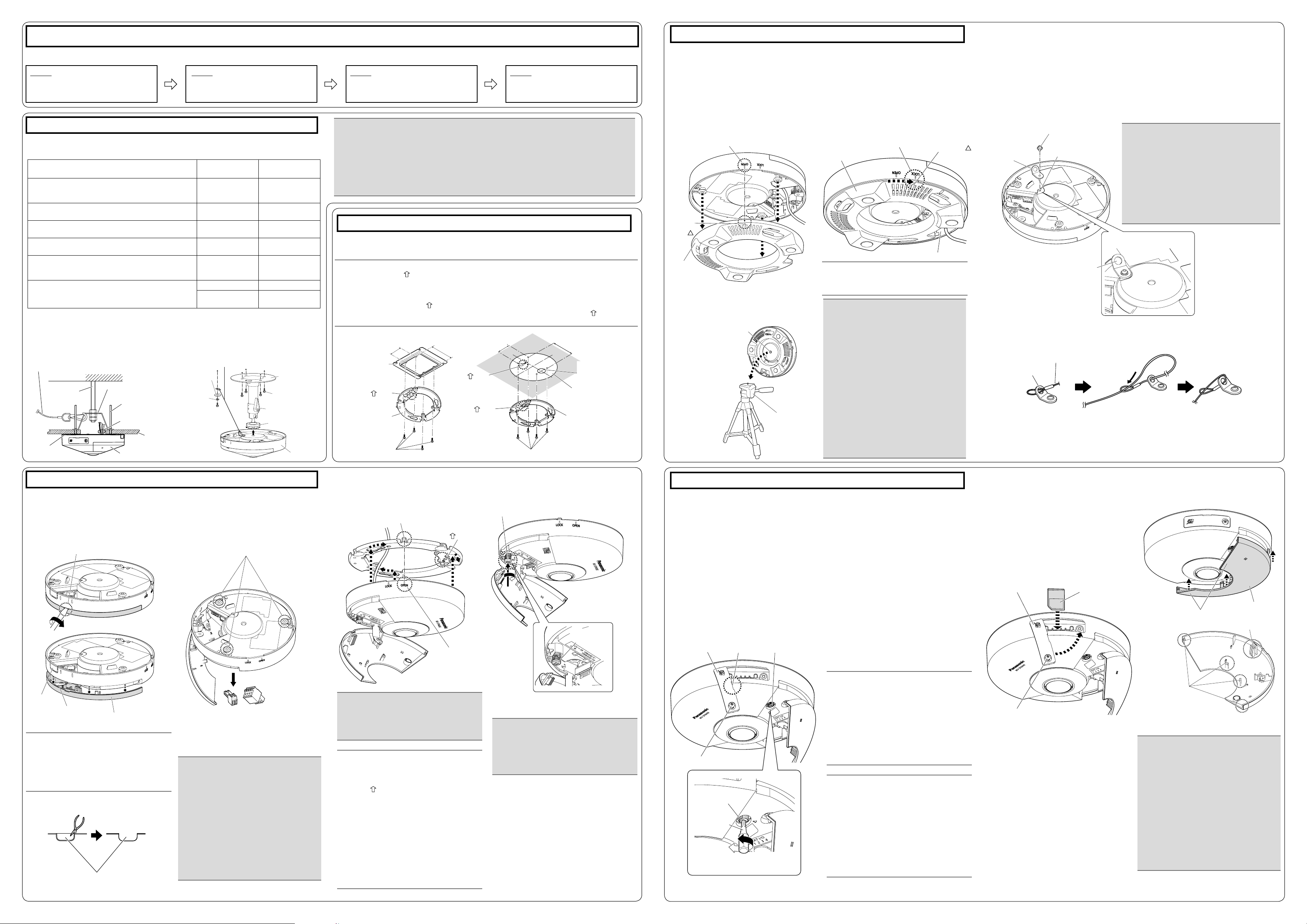
Step3 Camera mounting
■ When using the attachment plate
1 Insert a thin slotted head screwdriver, etc.
into the sub cover groove of the camera,
rotate the slotted head screwdriver as
shown in the illustration below, and then
remove the sub cover.
Sub cover groove
Side cable
access hole
Sub cover sheet
Sub cover
Side cable access hole
2 Remove the D power cord plug (acces-
sory) and E external I/O terminal plug
(accessory) attached to the camera.
3 Check the position of the 3 attachment
mounting screws on the bottom side of the
camera.
Attachment mounting screws
* Wiring and the sub cover are not shown in
some illustrations from this point.
4 Connect cables to the camera according to the
instructions in “Making connections”, and x
the camera by inserting attachment mounting screws into the holes of the A attachment
plate (accessory).
Protruding part
TOP
OPEN mark
5 Secure the camera using the camera xing
screw. (Recommended tightening torque:
0.78 N·m {0.58 lbf·ft})
Camera xing screw
Camera xing
screw
Step4 Adjustment
1 Loosen the SD memory card slot cover x-
ing screw on the side of the camera using
the B bit (accessory), then insert the tip of
a small slotted head screwdriver, etc. into
the notched area to remove the SD memory
card slot cover.
2 Remove the cover lm from the lens sur-
face.
3 Turn on the camera. The LINK indicator
inside the SD memory card slot cover lights.
Make sure that the ACT indicator is blinking.
(Refer to the descriptions in “Major operating controls” for more information about the
indicators.)
* After turning on the camera, there may be
a sound produced from the lens for several
seconds. This is not a malfunction.
Notched areaSD memory card
slot cover
SD memory card slot cover xing
screw
Image rotation gear
B Bit
(accessory)
* Part of the sub cover is not shown.
Image rotation gear
4 Perform camera settings while referring to
the included “Congure the settings of the
camera” (leaet), and check if camera images are displayed on the PC monitor.
5 Align the upwards direction of the image
while rotating the image rotation gear and
checking the image on the PC monitor.
Rotate the image rotation gear using the bit
(accessory), and align the upwards direction of
the image as necessary.
Rotating the image rotation gear clockwise
also rotates the PC image clockwise. Rotating
the image rotation gear counterclockwise also
rotates the PC image counterclockwise.
Adjustable range of the PC image
-45° to +45°
The default position of the image rotation ●
gear is 0°.
6 Insert an SD memory card into the slot, if
necessary.
Insert the SD memory card with its label ●
facing down.
7 Close the SD memory card slot cover, and
tighten the SD memory slot cover slot cover
xing screw to secure the cover.
(Recommended tightening torque: 0.39 N·m
{0.29 lbf·ft})
SD memory card
slot cover
SD memory card slot cover xing screw
SD memory card
* Part of the sub cover is not shown.
To remove the SD memory card, hold down ●
the SD ON/OFF button for about 2 seconds.
When the flashing SD MOUNT indicator
goes out, you can remove the SD memory
card.
After the SD memory card has been ●
replaced, press the SD ON/OFF button, and
make sure the SD MOUNT indicator is continually lit.
If you do not press the SD ON/OFF button ●
after replacing the SD memory card, the SD
MOUNT indicator is continually lit approximately 5 minutes later.
8 Return the sub cover to its original position
and secure it.
Sub cover exterior
Sub cover interior
Sub cover exterior hook
Sub cover
interior hook
Secure the sub cover exterior hook rst, ●
then push in the interior hook.
* When removing the camera, perform
removal by following the installation
procedure in the reverse order.
 Loading...