

Panasonic SCHTB770 User Manual [da]
Operating Instructions
Home Theater Audio System
Model No. SC-HTB770
Thank you for purchasing this product.
Please read these instructions carefully before using this product, and save this manual for future use.
Model number suffix “EB” denotes UK model.
EG EB GN
RQT9849-B

Table of contents
Safety precautions
WARNING CAUTION
Unit
≥ To reduce the risk of fire, electric shock or
product damage,
jDo not expose this unit to rain, moisture,
dripping or splashing.
jDo not place objects filled with liquids, such
as vases, on this unit.
jUse only the recommended accessories.
jDo not remove covers.
jDo not repair this unit by yourself. Refer
servicing to qualified service personnel.
AC mains lead
≥ To reduce the risk of fire, electric shock or
product damage,
jEnsure that the power supply voltage
corresponds to the voltage printed on this
unit.
jInsert the mains plug fully into the socket
outlet.
jDo not pull, bend, or place heavy items on the
lead.
jDo not handle the plug with wet hands.
jHold onto the mains plug body when
disconnecting the plug.
jDo not use a damaged mains plug or socket
outlet.
≥ The mains plug is the disconnecting device.
Install this unit so that the mains plug can be
unplugged from the socket outlet immediately.
Button-type battery (Lithium battery)
≥ Risk of fire, explosion and burns. Do not
recharge, disassemble, heat above 60
incinerate.
≥ Keep the Button-Type battery out of the reach of
children. Never put Button-Type battery in
mouth. If swallowed call your doctor.
o
C or
Unit
≥ Do not place sources of naked flames, such as
lighted candles, on this unit.
≥ This unit may receive radio interference caused
by mobile telephones during use. If such
interference occurs, please increase separation
between this unit and the mobile telephone.
≥ This unit is intended for use in moderate
climates.
Placement
≥ Place this unit on an even surface.
≥ To reduce the risk of fire, electric shock or
product damage,
jDo not install or place this unit in a bookcase,
built-in cabinet or in another confined space.
Ensure this unit is well ventilated.
jDo not obstruct this unit’s ventilation openings
with newspapers, tablecloths, curtains, and
similar items.
jDo not expose this unit to direct sunlight, high
temperatures, high humidity, and excessive
vibration.
Button-type battery (Lithium battery)
≥ Danger of explosion if battery is incorrectly
replaced. Replace only with the type
recommended by the manufacturer.
≥ Insert with poles aligned.
≥ Mishandling of batteries can cause electrolyte
leakage and may cause a fire.
jRemove the battery if you do not intend to use
the remote control for a long period of time.
Store in a cool, dark place.
jDo not heat or expose to flame.
jDo not leave the battery(ies) in a car exposed
to direct sunlight for a long period of time with
doors and windows closed.
≥ When disposing the batteries, please contact
your local authorities or dealer and ask for the
correct method of disposal.
RQT9849
2
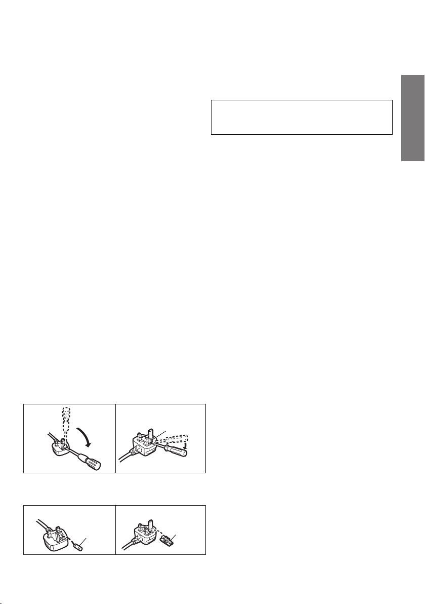
Caution for AC Mains
Figure A Figure B
Fuse cover
Figure A Figure B
Fuse
(5 ampere)
Fuse
(5 ampere)
Lead
(For the AC mains plug of three pins)
For your safety, please read the following text
carefully.
This appliance is supplied with a moulded three
pin mains plug for your safety and convenience.
A 5-ampere fuse is fitted in this plug.
Should the fuse need to be replaced please
ensure that the replacement fuse has a rating of
5-ampere and that it is approved by ASTA or BSI
to BS1362.
Check for the ASTA mark Ï or the BSI mark Ì
on the body of the fuse.
If the plug contains a removable fuse cover you
must ensure that it is refitted when the fuse is
replaced.
If you lose the fuse cover the plug must not be
used until a replacement cover is obtained.
A replacement fuse cover can be purchased from
your local dealer.
Before use
Remove the connector cover.
How to replace the fuse
The location of the fuse differ according to the type
of AC mains plug (figures A and B). Confirm the AC
mains plug fitted and follow the instructions below.
Illustrations may differ from actual AC mains plug.
1. Open the fuse cover with a screwdriver.
2. Replace the fuse and close or attach the fuse cover.
About Bluetooth
Panasonic bears no responsibility for data
and/or information that is compromised
during a wireless transmission.
®
∫ Frequency band used
This system uses the 2.4 GHz frequency band.
∫ Certification of this device
≥
This system conforms to frequency restrictions
and has received certification based on frequency
laws. Thus, a wireless permit is not necessary.
≥
The action below are punishable by law in some countries:
jTaking apart or modifying the unit.
jRemoving specification indications.
∫ Restrictions of use
≥ Wireless transmission and/or usage with all
Bluetooth
≥ All devices must conform to standards set by
Bluetooth SIG, Inc.
≥ Depending on the specifications and settings of
a device, it can fail to connect or some
operations can be different.
≥ This system supports Bluetooth
features. But depending on the operating
environment and/or settings, this security is
possibly not sufficient. Transmit data wirelessly
to this system with caution.
This system cannot transmit data to a Bluetooth® device.
≥
®
equipped devices is not guaranteed.
®
security
∫ Range of use
Use this device at a maximum range of 10 m.
The range can decrease depending on the
environment, obstacles or interference.
∫ Interference from other devices
≥
This system may not function properly and
troubles such as noise and sound jumps may
arise due to radio wave interference if the main
unit is located too close to other Bluetooth
devices or the devices that use the 2.4 GHz band.
≥
This system may not function properly if radio waves
from a nearby broadcasting station, etc. are too strong.
®
∫ Intended usage
≥ This system is for normal, general use only.
≥ Do not use this system near equipment or in an
environment that is sensitive to radio frequency
interference (example: airports, hospitals,
laboratories, etc.).
RQT9849
Precautions
3

Table of contents
Safety precautions ........................................................................................... 2
Caution for AC Mains Lead ............................................................................. 3
About Bluetooth
Before use
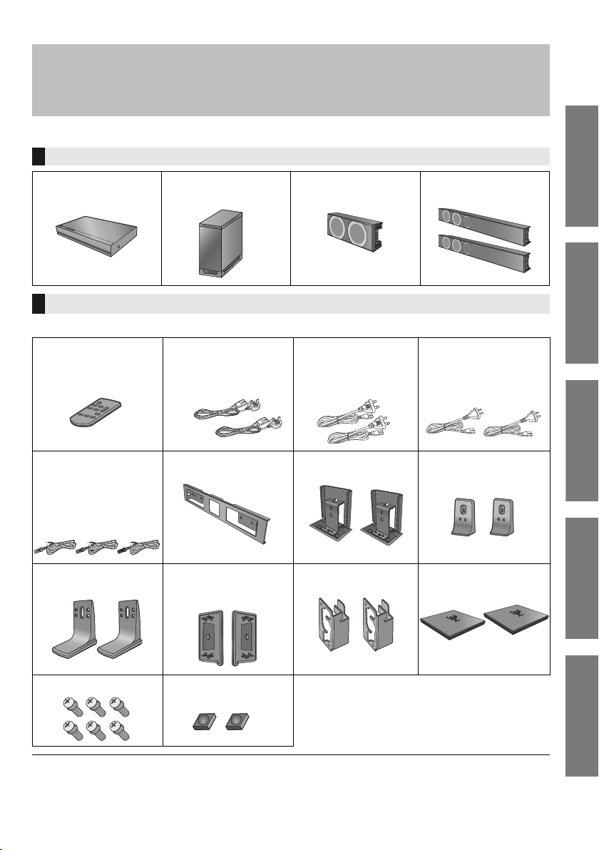
Supplied items .................................................................................................. 5
This system (SC-HTB770) .................................................................................................. 5
Accessories ........................................................................................................................ 5
Control reference guide ................................................................................... 6
This system (Front) ............................................................................................................. 6
This system (Rear) .............................................................................................................7
Remote control ................................................................................................................... 8
Getting started
Step 1 Selecting the placement method ....................................................... 9
The speaker system ......................................................................................................... 10
The active subwoofer ....................................................................................................... 10
Wireless interference ........................................................................................................ 10
Step 2 Assembling the speakers ................................................................. 11
When attaching the speakers to a wall ............................................................................. 11
When placing the speakers on a table ............................................................................. 18
Additional speaker fall prevention measures .................................................................... 23
Step 3 Connections ....................................................................................... 25
Connection with the TV .................................................................................................... 25
Connection with other devices .......................................................................................... 26
Speaker cable connection ................................................................................................ 27
AC mains lead connection ................................................................................................ 27
Active subwoofer wireless connection .............................................................................. 28
Bluetooth
Operations
®
............................................................................................. 3
®
connection ...................................................................................................... 28
Using this system .......................................................................................... 29
3D sound ......................................................................................................... 30
Sound modes ................................................................................................................... 30
Linked operations with the TV (VIERA Link “HDAVI ControlTM”) .............. 31
Advanced operations ..................................................................................... 32
Reference
Troubleshooting ............................................................................................. 34
Indicator illumination ..................................................................................... 37
Specifications ................................................................................................. 38
Unit care .......................................................................................................... 39
Licenses .......................................................................................................... 39
Limited Warranty (ONLY FOR AUSTRALIA) ................................................ 43
RQT9849
4
Getting started
Before use
≥ The illustrations shown may differ from your unit.
≥ These operation instructions are applicable to model SC-HTB770 for variety of regions.
Unless otherwise indicated, illustrations in these operating instructions are of the model for the United Kingdom and Ireland.
≥ Operations in this operating instructions are described mainly with the remote control, but you can
perform the operations on the main unit if the controls are the same.
Supplied items
This system (SC-HTB770)
∏ 1 Main unit
(SU-HTB770)
∏ 1
Active subwoofer
(SB-HWA770)
Accessories
Check the supplied accessories before using this system.
∏ 1 Remote control
(with a battery)
(N2QAYC000083)
∏ AC mains lead
2 For the United
Kingdom and Ireland
(K2CT2YY00097)
∏ 1 Centre speaker
(SB-HTB770)
2 For Continental
Europe
(K2CQ2YY00119)
∏ 2 Front speakers
(SB-HTB570)
2 For Australia and
New Zealand
(K2CJ2YY00093)
Precautions
Before use
∏ 3 Speaker cables
(REE1789: RED)
(REE1790: WHITE)
Length: 3 m
(REE1791: GREEN)
Length: 2 m
∏ 2 Leg stands
(RGK2463)
Screws (XYN5+J14FJK)
∏ 6
≥ Product numbers are correct as of February 2013. These may be subject to change.
≥ The supplied AC mains lead is for use with this system only.
Do not use it with other equipment. Also, do not use cords from other equipment with this system.
∏ 1 Metal bracket
(RML0760)
∏ 2 Side caps
(RGK2445: R)
(RGK2446: L)
∏ 2 Speaker feet
(RKAX0042-K)
∏ 2 Stand necks
(RGK2444)
∏ 2 Hook brackets
(RML0763)
∏ 2 Support legs
(RGK2464)
∏ 2 Speaker bases
(RGK2465)
RQT9849
Operations
Reference
5
Control reference guide
Main unit
Active subwoofer
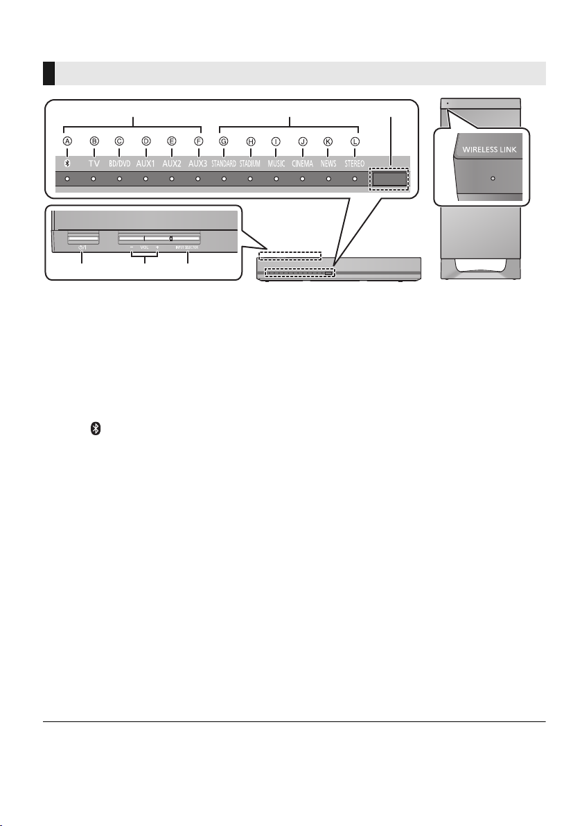
This system (Front)
456
7
1
2
3
1 Standby/on switch (Í/I)
Press to switch the unit from on to standby
mode or vice versa. In standby mode, the unit
is still consuming a small amount of power.
2 Adjust the volume of this system
3 Select the input source
“TV”---------#“BD/DVD”---------#“AUX1”
^-- “”(- “AUX3”(- “AUX2”(}
4 Input selector indicators*
A Bluetooth® indicator
Lights blue when the Bluetooth
1
®
the audio source
B TV indicator
Lights green when the TV is the audio
source
C BD/DVD indicator
Lights amber when the device connected
to the BD/DVD terminal is the audio
source
D AUX1 indicator
Lights amber when the device connected
to the AUX1 terminal is the audio source
E AUX2 indicator
Lights amber when the device connected
to the AUX2 terminal is the audio source
F AUX3 indicator
Lights amber when the device connected
to the AUX3 terminal is the audio source
device is
5 Sound mode indicators*
1
G STANDARD indicator
Lights when STANDARD is the current
sound mode
H STADIUM indicator*
2
Lights when STADIUM is the current
sound mode
I MUSIC indicator*
2
Lights when MUSIC is the current sound
mode
J CINEMA indicator
Lights when CINEMA is the current
sound mode
K NEWS indicator
Lights when NEWS is the current sound
mode
L STEREO indicator
Lights when STEREO is the current
sound mode
6 Remote control signal sensor (> 8)
7 WIRELESS LINK indicator (> 28)
*1
The indicators will also blink in various conditions. (> 37)
*2
The indicator blinks for 5 sec when the main unit detects an audio format.
To manually verify the current audio format and the corresponding indicators, refer to page 32 (Audio
format indicator).
RQT9849
6
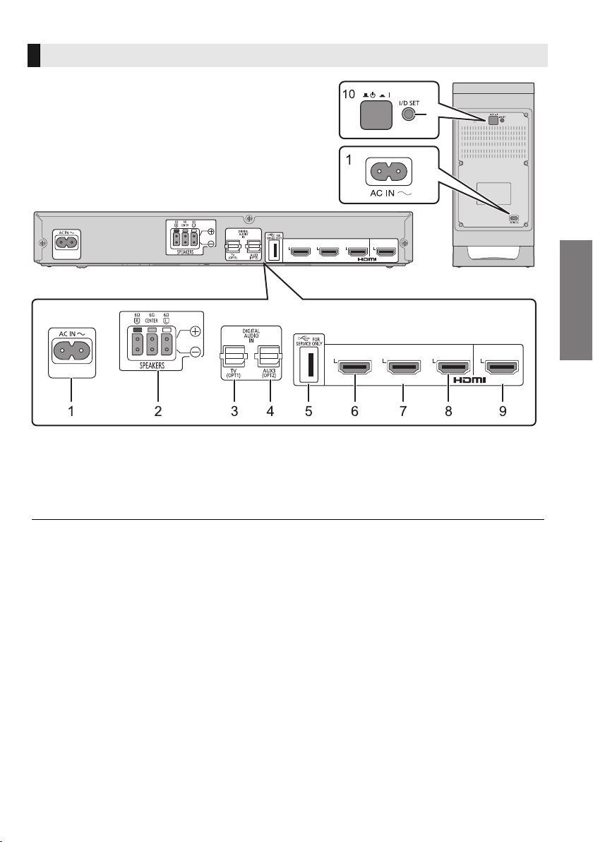
This system (Rear)
*
1 AC IN terminal (> 27)
2 Speaker terminals (> 27)
3 TV terminal (> 25)
4 AUX3 terminal (> 26)
5 USB port (for service use only)
AUX2
(HDMI3)
6 AUX2 terminal (> 26)
7 AUX1 terminal (> 26)
8 BD/DVD terminal (> 26)
9 HDMI OUT terminal (ARC compatible) (>25)
10 Active subwoofer on/off button (> 28)
AUX1
(HDMI2)
AV IN
AUX2
(HDMI3)
BD/DVD
(HDMI1)
TV
(ARC)
AUX1
(HDMI2)
AV OUT
AV IN
BD/DVD
(HDMI1)
TV
(ARC)
AV OUT
* The I/D SET button is only used when the main unit is not paired with the active subwoofer. (> 36)
Before use
RQT9849
7
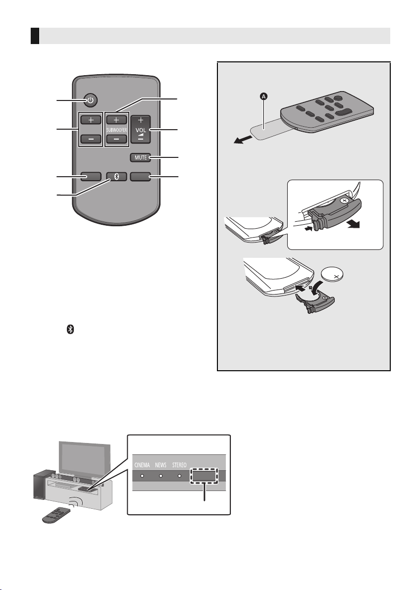
Remote control
DIALOG LEVEL
LINK MODE
PAIRING
----
SOUND
1
6
7
2
3
4
5
8
INPUT
SELECTOR
B Remote control signal sensor
≥ Operation range
Distance: Within approx. 7 m
directly in front
Angle: Approx. 30
o
left and right
1 Turn the main unit on or off (> 29)
2 Adjust the dialog effect level (> 29)
3 Adjust the output level of the active
subwoofer (bass sound) (> 29)
4 Adjust the volume of this system (> 29)
5 Mute the sound (> 29)
6 Select the input source (> 29)
“TV”---------#“BD/DVD”---------#“AUX1”
^--- “”( “AUX3”( “AUX2”(}
7 Select the Bluetooth
(> 29)
8 Select the sound mode (> 30)
“STANDARD” ----#“STADIUM” -----#“MUSIC”
^- “STEREO”( “NEWS”( “CINEMA”(}
®
device as the source
∫ Before using for the first time
Remove the insulation sheet A.
∫ To replace a button-type battery
Battery type: CR2025 (Lithium battery)
≥ Set the button-type battery with its (i) mark
facing upward.
≥ Keep the button-type battery out of reach of
children to prevent swallowing.
∫ Remote control operation range
The remote control signal sensor is located on the main unit.
≥Use the remote control within the correct operation range.
RQT9849
8
Getting started
Getting started
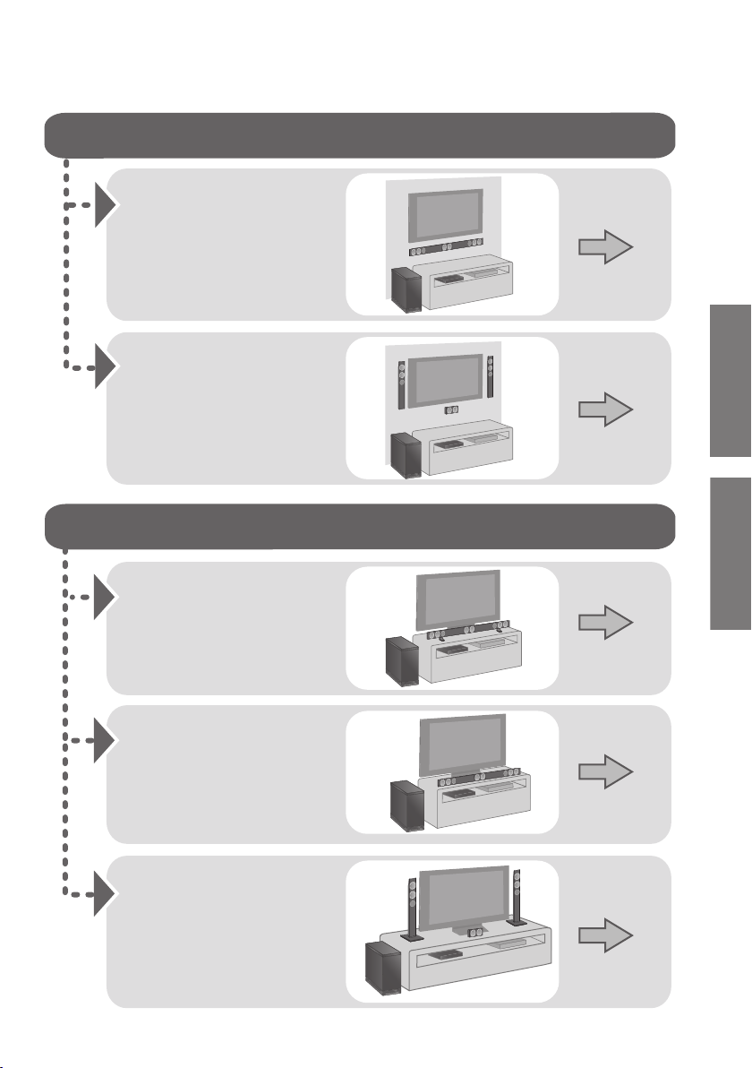
When attaching the speakers to a wall
When placing the speakers on a table
Place the speakers
horizontally
Page 11
Place the front speakers
vertically
Place the speakers using
the leg stands
Place the front speakers
using the speaker bases
Page 14
Page 18
Page 19
Page 20
Place the speakers using
the support legs and
speaker feet
Step 1 Selecting the placement method
≥Choose a placement method that suits you best.
Before use
RQT9849
9
Caution
≥ This system is to be used only as indicated in these instructions. Failure to do so may lead to damage to the amplifier and/
or the speakers, and may result in the risk of fire. Consult a qualified service person if damage has occurred or if you
experience a sudden change in performance.
≥ Do not attempt to attach the speakers to a wall using methods other than those described in this manual.
The speaker system
≥Use a screwdriver (i) for assembling the speakers.
≥Do not hold the speakers in one hand to avoid injury, you may drop the speakers when carrying them.
∫ When attaching the speakers to a wall
The wall or pillar on which the speakers are to be attached should be capable of supporting 33 kg per screw. Consultation with
a qualified installation specialist is recommended when attaching the speakers to a wall. Improper attachment may result in
damage to the wall and speakers, and personal injury.
∫ When placing the speakers in front of the TV
The speakers may block or interfere with the TV’s various sensors (C.A.T.S. (Contrast Automatic Tracking System) sensor,
remote control sensor, etc.) and the 3D Eyewear transmitters on a 3D compatible TV.
≥ If the leg stands are being used
Change the height of the leg stands and/or move the speakers further away from the TV. If the TV still does not function
correctly, try removing the leg stands.
≥ If the leg stands are not used
Move the speakers further away from the TV. If the TV still does not function properly, try placing them beside the TV (> 9).
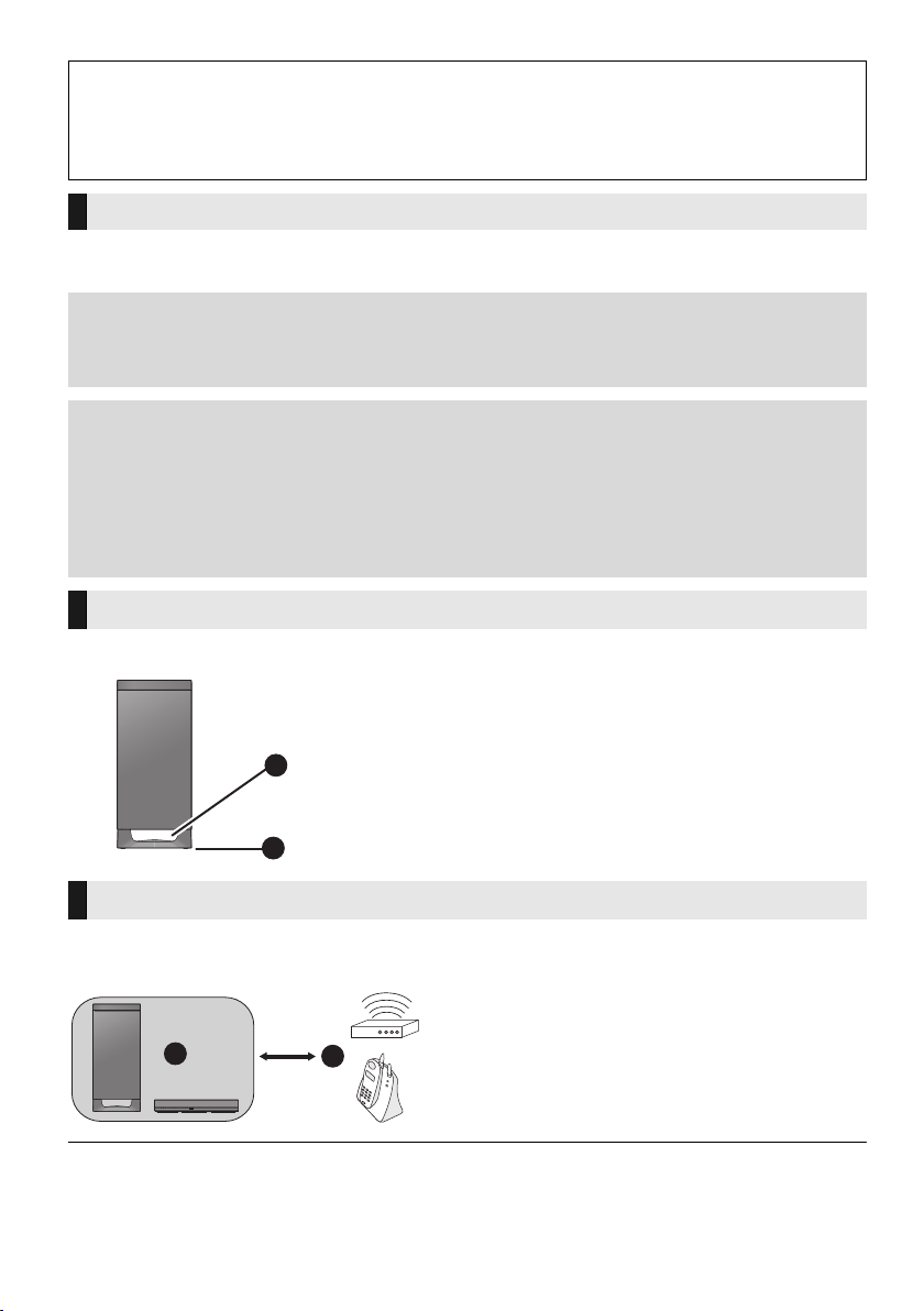
The active subwoofer
When carrying the active subwoofer
A Do not hold the active subwoofer from this
opening.
The parts inside may get damaged.
A
B Always hold the bottom of the active subwoofer when
moving it.
B
Wireless interference
To avoid interference, maintain the following distances between the main unit/active subwoofer
and other electronic devices that use the same radio frequency (2.4 GHz band).
C Main unit/active subwoofer
D Wireless router, cordless phone and other
C
≥ Place the active subwoofer within a few meters of the main unit and in a horizontal position with the top panel facing upward.
≥ Do not use the main unit or the active subwoofer in a metal cabinet.
≥
Placing the active subwoofer too close to the walls and corners can result in excessive bass. Cover walls and windows with thick curtains.
≥
If irregular colouring occurs on your TV, turn the TV off for about 30 minutes. If it persists, move the speakers further away from the TV.
≥
Keep magnetised items away. Magnetised cards, watches, etc., can be damaged if placed too close to the active subwoofer and the speakers.
RQT9849
10
D
electronic devices: approx. 2 m

Getting started
Step 2 Assembling the speakers
When attaching the speakers to a wall
Place the speakers horizontally
The speakers can be wall mounted by drilling screws into the wall, etc.
Make sure that the screw used and the wall are strong enough to support the weight of at least 33 kg.
The screws and other items are not supplied as the type and size will vary with each installation.
For details about the required screws, refer to the diagram below the step “Drive a screw into the wall.”(>
≥
∏ 2 Front
speakers
∏ 1 Metal bracket ∏ 4 Screws
≥For a safety measure to prevent the speakers from falling, refer to page 23.
≥To prevent damage or scratches, lay down a soft cloth and perform the assembly on it.
∏ 1 Centre
speaker
∏ 3 Speaker cables
WHITE: Left
RED: Right
GREEN: Centre
Assemble the speakers.
≥ There is no left and right for the centre speaker.
≥ The two front speakers are interchangeable.
≥ Keep the screws out of reach of children to prevent swallowing.
12).
A Screw (supplied)
≥ Tighten securely.
RQT9849
11
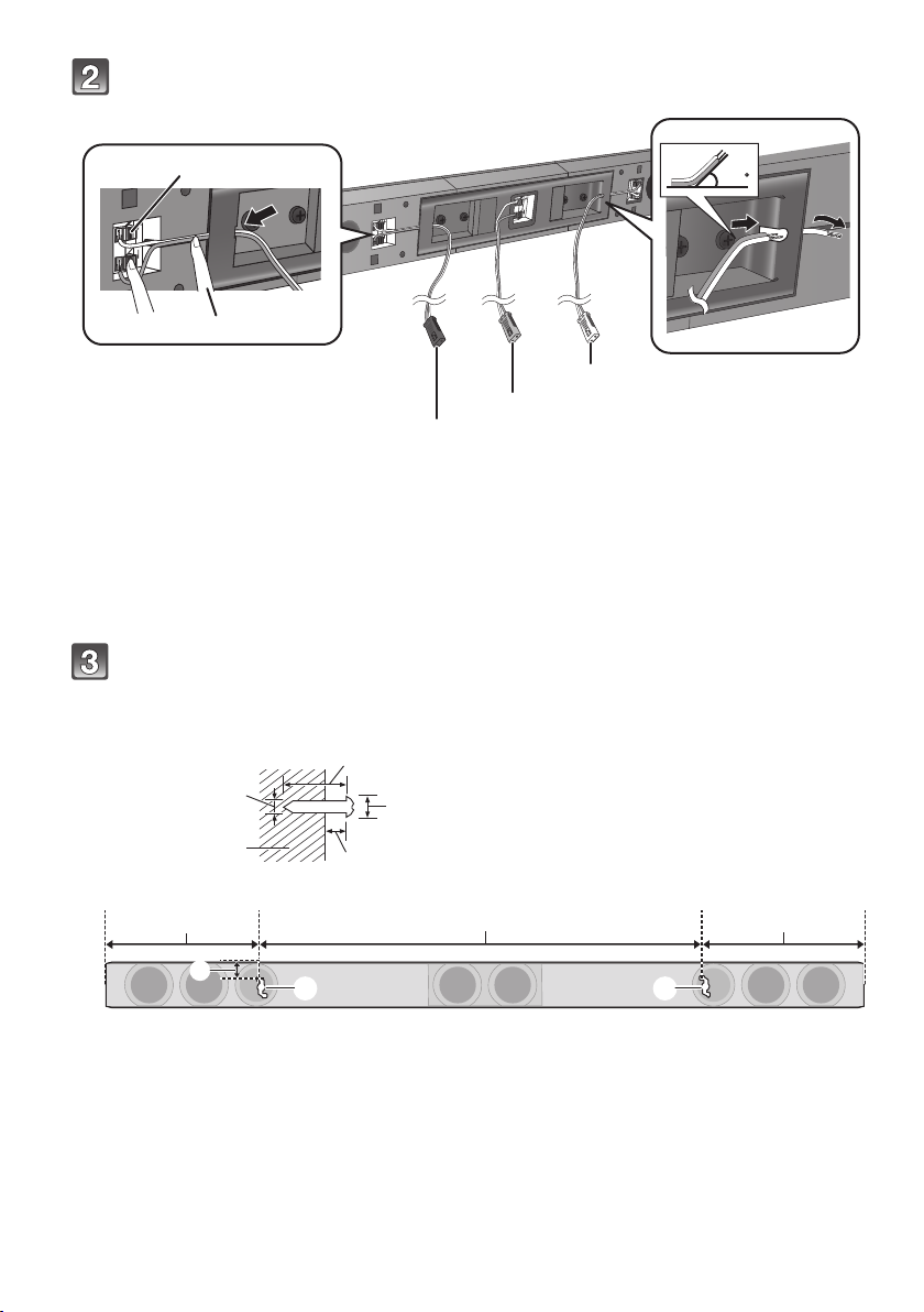
Connect the speaker cables.
Push
Red
White
Green
Front view (semi-transparent image)
*
45
1 Insert the wire fully.
r: White
s: Blue line
≥ Insert the wire fully, taking care not to insert
beyond the wire insulation.
2 Press into the groove.
* If you have difficulty inserting the cable, try straightening the speaker cable and then bending the
cable about 20 mm from the tip, at an angle of approx. 45o
Drive a screw into the wall.
≥ Use the measurements indicated below to identify the screwing positions on the wall.
≥ Leave at least 20 mm of space above and on each side of the speaker to allow enough space for fitting the speaker.
≥ Keep the screws out of reach of children to prevent swallowing.
A Right speaker connector
B Centre speaker connector
C Left speaker connector
(as illustrated above).
A At least 30 mm
B ‰4.0 mm
C ‰7.0 mm to ‰9.4 mm
D Wall or pillar
E 5.5mm to 6.5mm
F 238 mm G 745 mm H 248 mm I 20 mm
J Wall mounting hole
RQT9849
12
Getting started
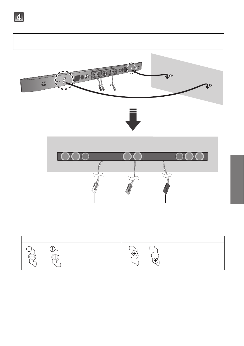
Wall mount the speakers:
White Red
Fit the speaker securely onto the screw(s).
Red connector: The speaker attached to the red connector cable is to be placed on the right side.
White connector:The speaker attached to the white connector cable is to be placed on the left side.
A Right speaker connector
B Left speaker connector
DO DO NOT
≥ Move the speaker so
that the screw is in
this position.
≥ In this position, the
speaker will likely fall
if moved to the left or
right.
RQT9849
13
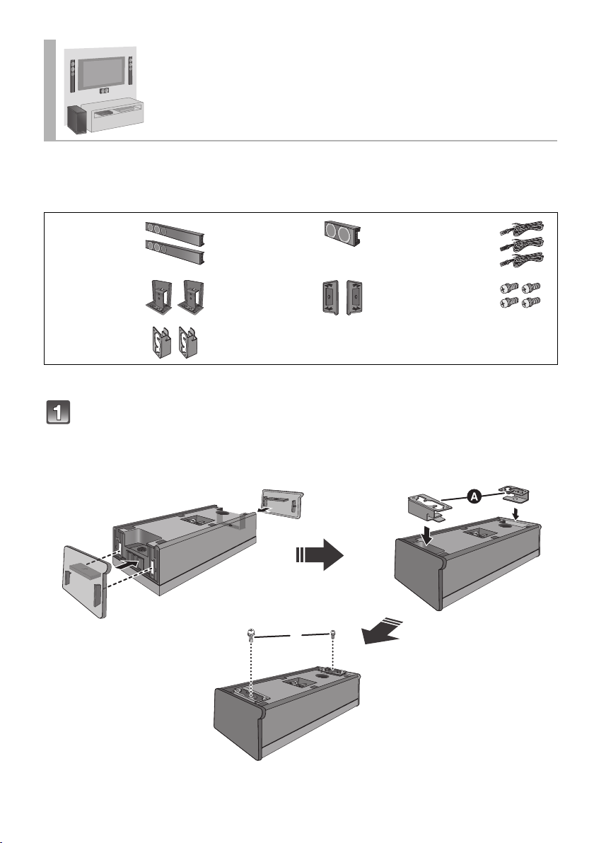
Place the front speakers vertically
The speakers can be wall mounted by drilling screws into the wall, etc.
Make sure that the screw used and the wall are strong enough to support the weight of at least 33 kg.
The screws and other items are not supplied as the type and size will vary with each installation.
For details about the required screws, refer to the diagram below the step “Drive a screw into the wall.”(>16).
≥
∏ 2 Front
speakers
∏ 2 Stand necks ∏ 2 Side caps ∏ 4 Screws
∏ 2 Hook
brackets
≥For a safety measure to prevent the speakers from falling, refer to page 23.
≥To prevent damage or scratches, lay down a soft cloth and perform the assembly on it.
∏ 1 Centre
speaker
∏ 3 Speaker cables
WHITE: Left
RED: Right
GREEN: Centre
Assemble the centre speaker:
Attach the side caps and hook brackets to the speaker.
≥ There is no left and right for the centre speaker.
≥ Keep the screws out of reach of children to prevent swallowing.
A Hook bracket (supplied) B Screw (supplied)
RQT9849
14
≥ Tighten securely.
 Loading...