

Panasonic SC-HTB500 Operating Instructions

Operating Instructions
EB
Home Theater Audio System
Model No. SC-HTB500
Dear customer
Thank you for purchasing this product.
For optimum performance and safety, please read these instructions carefully.
Before connecting, operating or adjusting this product, please read the instructions completely.
Please keep this manual for future reference.
The illustrations shown may differ from your unit.
Included Wall Mounting Installation Instructions
The installation should never be done by any other than a qualified installation
specialist.
Before commencing work, carefully read these wall mounting installation instructions and the
operating instructions to ensure that installation is performed correctly.
(Please keep these instructions. You may need them when maintaining or moving this unit.)
Model number suffix “EB” denotes UK model.
RQTX1182-B

WARNING:
TO REDUCE THE RISK OF FIRE, ELECTRIC SHOCK OR PRODUCT DAMAGE,
≥ DO NOT EXPOSE THIS APPARATUS TO RAIN, MOISTURE, DRIPPING OR SPLASHING
AND THAT NO OBJECTS FILLED WITH LIQUIDS, SUCH AS VASES, SHALL BE PLACED
ON THE APPARATUS.
≥ USE ONLY THE RECOMMENDED ACCESSORIES.
≥ DO NOT REMOVE THE COVER (OR BACK); THERE ARE NO USER SERVICEABLE PARTS
INSIDE. REFER SERVICING TO QUALIFIED SERVICE PERSONNEL.
CAUTION!
≥ DO NOT INSTALL OR PLACE THIS UNIT IN A BOOKCASE, BUILT-IN CABINET OR IN
ANOTHER CONFINED SPACE. ENSURE THE UNIT IS WELL VENTILATED. TO PREVENT
RISK OF ELECTRIC SHOCK OR FIRE HAZARD DUE TO OVERHEATING, ENSURE THAT
CURTAINS AND ANY OTHER MATERIALS DO NOT OBSTRUCT THE VENTILATION
VENTS.
≥ DO NOT OBSTRUCT THE UNIT’S VENTILATION OPENINGS WITH NEWSPAPERS,
TABLECLOTHS, CURTAINS, AND SIMILAR ITEMS.
≥ DO NOT PLACE SOURCES OF NAKED FLAMES, SUCH AS LIGHTED CANDLES, ON THE
UNIT.
≥ DISPOSE OF BATTERIES IN AN ENVIRONMENTALLY FRIENDLY MANNER.
Warning
Risk of fire, explosion and burns. Do not recharge, disassemble, heat above 60oC or incinerate.
THIS UNIT IS INTENDED FOR USE IN MODERATE CLIMATES.
The socket outlet shall be installed near the equipment and easily accessible.
The mains plug of the power supply cord shall remain readily operable.
To completely disconnect this apparatus from the AC Mains, disconnect the power supply cord
plug from AC receptacle.
This product may receive radio interference caused by mobile telephones during use. If such
interference is apparent, please increase separation between the product and the mobile
telephone.
2
Caution for AC Mains Lead
Figure A Figure B
Fuse
cover
Figure A Figure B
Fuse
(5 ampere)
Fuse
(5 ampere)
For your safety, please read the following text
carefully.
This appliance is supplied with a moulded three
pin mains plug for your safety and convenience.
A 5-ampere fuse is fitted in this plug.
Should the fuse need to be replaced please
ensure that the replacement fuse has a rating of
5-ampere and that it is approved by ASTA or
BSI to BS1362.
Check for the ASTA mark Ï or the BSI mark Ì
on the body of the fuse.
If the plug contains a removable fuse cover you
must ensure that it is refitted when the fuse is
replaced.
If you lose the fuse cover the plug must not be
used until a replacement cover is obtained.
A replacement fuse cover can be purchased
from your local dealer.
CAUTION!
IF THE FITTED MOULDED PLUG IS
UNSUITABLE FOR THE SOCKET OUTLET
IN YOUR HOME THEN THE FUSE SHOULD
BE REMOVED AND THE PLUG CUT OFF
AND DISPOSED OF SAFELY.
THERE IS A DANGER OF SEVERE
ELECTRICAL SHOCK IF THE CUT OFF
PLUG IS INSERTED INTO ANY
13-AMPERE SOCKET.
WARNING: DO NOT CONNECT EITHER
WIRE TO THE EARTH TERMINAL WHICH
IS MARKED WITH THE LETTER E, BY THE
EARTH SYMBOL Ó OR COLOURED
GREEN OR GREEN/YELLOW.
THIS PLUG IS NOT WATERPROOF—KEEP
DRY.
Before use
Remove the connector cover.
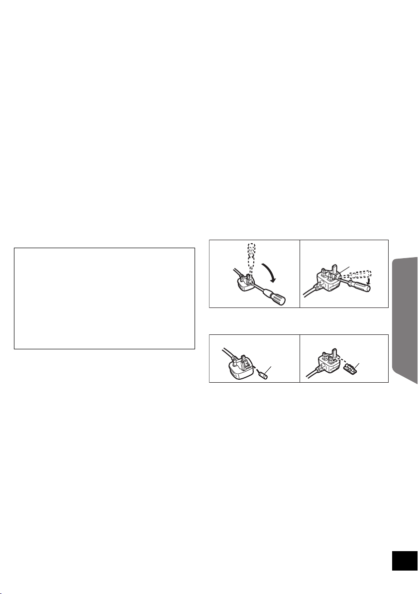
How to replace the fuse
The location of the fuse differ according to the
type of AC mains plug (figures A and B).
Confirm the AC mains plug fitted and follow the
instructions below.
Illustrations may differ from actual AC mains
plug.
1. Open the fuse cover with a screwdriver.
2. Replace the fuse and close or attach the fuse
cover.
If a new plug is to be fitted please observe the
wiring code as stated below.
If in any doubt please consult a qualified
electrician.
IMPORTANT
The wires in this mains lead are coloured in
accordance with the following code:
Blue: Neutral, Brown: Live.
As these colours may not correspond with the
coloured markings identifying the terminals in
your plug, proceed as follows:
The wire which is coloured Blue must be
connected to the terminal which is marked with
the letter N or coloured Black or Blue.
The wire which is coloured Brown must be
connected to the terminal which is marked with
the letter L or coloured Brown or Red.
Operating Instructions
3

TABLE OF CONTENTS
Operating Instructions
Caution for AC Mains Lead .................................................................................. 3
Accessories ........................................................................................................... 5
Unit care ................................................................................................................. 5
Control reference guide ........................................................................................ 6
This unit and active subwoofer (Front) .............................................................................6
This unit and active subwoofer (Rear) ..............................................................................6
Remote control .................................................................................................................7
Placement .............................................................................................................. 8
This unit ............................................................................................................................ 8
The Active subwoofer ....................................................................................................... 9
Assembling the unit ............................................................................................ 10
Connections ........................................................................................................ 11
Connection to a TV ......................................................................................................... 11
Connection from an HDMI compatible device ................................................................12
Digital transmitter connection .........................................................................................12
AC mains lead connection ..............................................................................................13
Active subwoofer wireless connection ............................................................................13
Using this unit ..................................................................................................... 14
Audio effects ....................................................................................................... 15
The various audio effects ................................................................................................ 15
Changing the audio effects .............................................................................................15
Linked operations with the TV
(VIERA Link “HDAVI Control
Specifications ...................................................................................................... 17
Audio information ............................................................................................... 18
Troubleshooting .................................................................................................. 18
Remote control code .......................................................................................................20
Using the IR Blaster ........................................................................................................ 21
Safety precautions .............................................................................................. 22
Licenses ............................................................................................................... 22
TM
”) ...................................................................... 16
Wall Mounting Installation Instructions
Safety Precautions .............................................................................................. 23
Components ........................................................................................................ 25
Installation procedure ......................................................................................... 25
Attaching the wall mount brackets ..................................................................................25
Connections ....................................................................................................................26
Placement .......................................................................................................................26
Attaching this unit to a wall .............................................................................................27
4

≥ Operations in these instructions are
described mainly with the remote control,
but you can perform the operations on
this unit if the controls are the same.
≥ Some accessories and external devices mentioned in these operating instructions that are
not supplied with this product may not be for sale in certain regions.
System SC-HTB500
This unit SU-HTB500
Active subwoofer SB-WA500
Accessories
Check the supplied accessories before using this unit.
∏ 1 Remote control
(Built-in battery)
(N2QAYC000027)
∏ 2 AC mains leads
(RFAX1027C)
∏ 2 Wall mount brackets
(RYQX1034-K)
∏ 2Screws
(RYQX1042-1)
∏ 1 Digital transmitter
(RFAX1032G)
∏ 2 Lock pins
(RYQX1048)
∏ 1 IR Blaster
(K2ZZ02C00007)
≥ Product numbers correct as of May 2010. These may be subject to change.
Unit care
∫ Clean this unit with a soft, dry cloth
≥Never use alcohol, paint thinner or benzine to clean this unit.
≥Before using chemically treated cloth, carefully read the instructions that came with the cloth.
∫ To dispose or transfer this unit
If you discard this unit either by disposal or transfer, then follow the procedure to return all the
settings to the factory presets to delete the user settings. (> 18, “To return to the factory preset.”)
∫ Sales and Support Information
Customer Care Centre
≥ For customers within the UK:
0844 844 3852
≥ For customers within the Republic of Ireland:
01 289 8333
≥ Visit our website for product information
www.panasonic.co.uk
≥ E-mail: customer.care@panasonic.co.uk
Direct Sales at Panasonic UK
≥ For customers: 0844 844 3856
≥ Order accessory and consumable items for
your product with ease and confidence by
phoning our Customer Care Centre
Monday-Thursday 9:00am-5:30pm, Friday
9:30am-5:30pm (Excluding public holidays).
≥ Or go on line through our Internet Accessory
ordering application at www.pas-europe.com
≥ Most major credit and debit cards accepted.
≥
All enquiries transactions and distribution facilities
are provided directly by Panasonic UK Ltd.
≥ It couldn’t be simpler!
≥ Also available through our Internet is direct
shopping for a wide range of finished
products, take a browse on our website for
further details.
Operating Instructions
.
5
Control reference guide
6 7
123 54
2
AC IN
3
4
5
6
2
AC IN
1
DIGITAL
TRANSMITTER
DIGITAL TRANSMITTER
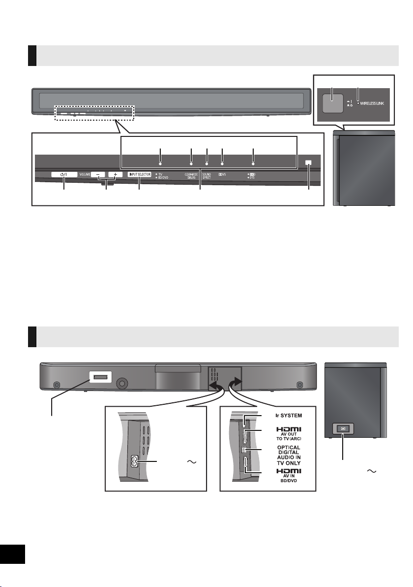
This unit and active subwoofer (Front)
1 Standby/on switch (Í/I)
Press to switch the unit from on to standby
mode or vice versa. In standby mode, the
unit is still consuming a small amount of
power.
2 Adjust the Volume of this unit
3 Select the source
“TV” !# “BD/DVD”
4 LED status indicators (> 14, 15)
A Audio source indicator
B Clear-mode Dialog indicator
C Sound Effect indicator
5 Remote control signal sensor
6 Active subwoofer on/off button
7 WIRELESS LINK indicator
This unit and active subwoofer (Rear)
D Dolby Virtual Speaker indicator
E Audio format indicator
Remote control operation range
Distance:
Within approx. 7 m
Angle:
Approx. 10
right
o
up and 30odown, 30oleft and
1 Digital transmitter dock (> 12)
2 AC IN terminal (> 13)
3 Ir SYSTEM terminal
(Only for use with the supplied IR Blaster.
(> 21))
6
4 HDMI AV OUT terminal (> 11 )
5 OPTICAL DIGITAL AUDIO IN terminal
(> 11)
6 HDMI AV IN terminal (> 12)
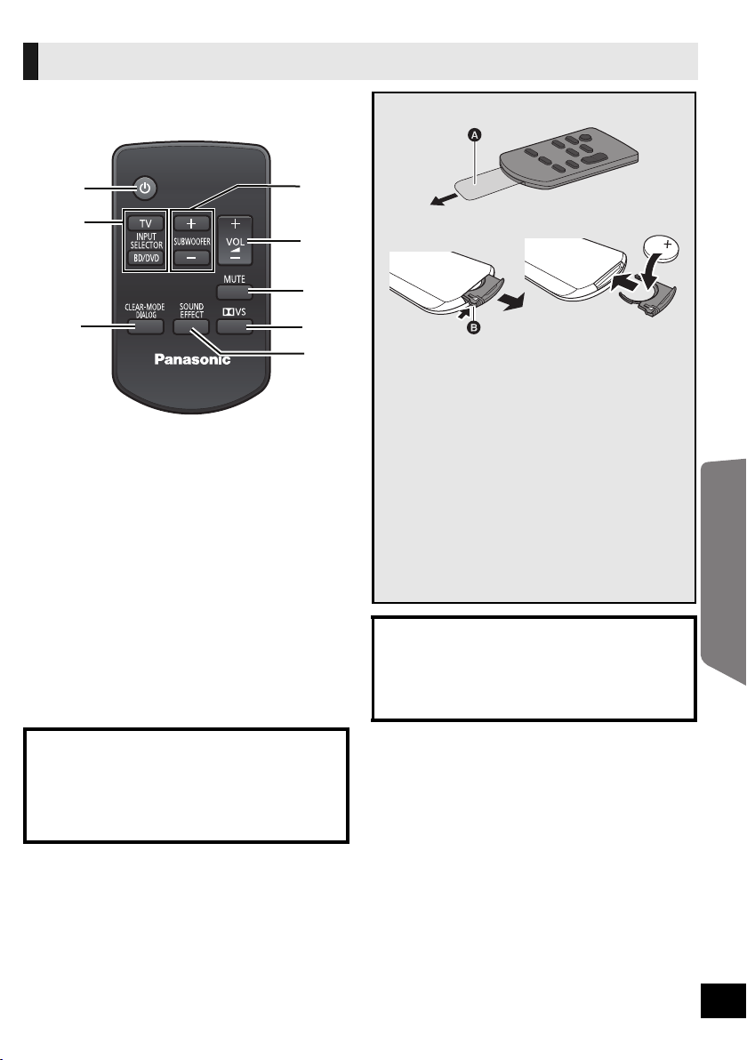
Remote control
1
2
3
4
5
6
7
8
1 Turn this unit on or off (> 14)
2 Select the source (> 14)
[TV]:
Select the TV as the source
[BD/DVD]:
Select the device connected to the HDMI
AV IN terminal as the source
3 Turn Clear-mode Dialog on or off (> 15)
4 Adjust the Subwoofer level of the active
subwoofer
5 Adjust the Volume of this unit
6 Mute the sound
7 Turn Dolby Virtual Speaker on or off (> 15)
8 Turn Sound Effect on or off (> 15)
Remove the insulation sheet A before using.
∫ To replace a button-type battery
1 While pressing the stopper B, pull out the
battery holder.
2 Set the button-type battery with its (i)
mark facing upward and then put the
battery holder back in place.
≥ When the button-type battery runs down,
replace it with a new battery (part number:
CR2025). The battery should normally last
about 1 year, however this depends on how
frequently the unit is used.
≥ Do not heat or expose to flame.
≥ Do not leave the battery(ies) in an
automobile exposed to direct sunlight for a
long period of time with doors and windows
closed.
Warning
Keep the Button-Type battery out of the
reach of children. Never put Button-Type
battery in mouth. If swallowed call your
doctor.
Operating Instructions
CAUTION
Danger of explosion if battery is incorrectly
replaced. Replace only with the same or
equivalent type recommended by the
manufacturer. Dispose of used batteries
according to the manufacturer’s instructions.
7

Placement
Caution
≥ This unit, the supplied wall mount brackets and the active subwoofer are to be used only as
indicated in these operating instructions or the wall mounting installation instructions.
Failure to do so may lead to damage to the amplifier and/or the speakers, and may result in
the risk of fire. Consult a qualified service person if damage has occurred or if you
experience a sudden change in performance.
≥ Do not attempt to attach this unit to a wall using methods other than those described in
this manual.
How you place this unit and the active subwoofer can affect the bass and the sound field.
This unit
Place this unit near the TV.
This unit should be placed parallel to the seating position.
E.g.,
On the wall
In a rack
§
1, 2, 3
On a table
§
1, 2, 3, 4, 5
To attach this unit to the wall, refer to the wall mounting installation
instructions. (> 23)
Installation work should never be done by any other than a qualified installation specialist.
§1 Place this unit on a flat secure base. (Do not place this unit on the TV’s pedestal.)
§2 To allow for proper ventilation and to allow for proper air flow around this unit, position it with at least 5 mm of
space on all sides of this unit.
§3 Secure the unit to prevent it from falling. (> 10)
§4Do not place this unit in front of a 3D compatible TV. This unit may block the transmitter for the 3D eyewear.
§
5 Do not place this unit too close to the TV. This unit may interfere with the TV’s various sensors (ambient light, etc.).
≥ You can damage the speakers and shorten their useful life if you play sound at high levels over extended
periods.
≥ Placing this unit too close to the floor, walls, and corners can result in excessive bass. Cover walls and windows
with thick curtains.
≥ Do not use the active subwoofer or this unit in a metal cabinet or bookshelf.
8
∫ If the TV’s remote control sensor is
A
B
C
blocked by this unit.
Try using the TV’s remote control from a
different angle. If the problem persists, you can
use the supplied IR Blaster to relay the signal to
the TV. (> 21)
≥ Do not use the IR Blaster if the TV’s remote
control sensor is not blocked by this unit.
∫ If irregular colouring occurs on your TV,
turn the TV off for about 30 minutes.
If it persists, move this unit further away from the
TV.
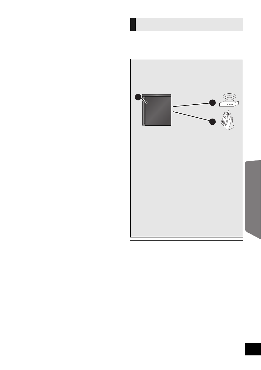
The Active subwoofer
Place to the right or left of the TV, on the
floor or on a sturdy shelf so that it will not
cause vibration. Leave about 30 cm from the
TV.
To avoid interference, maintain the
following distances between the active
subwoofer and other electronic devices
that use the same radio frequency (2.4 GHz
band).
A Active subwoofer
B Wireless LAN: approx. 2 m
C Cordless phone and other electronic
devices: approx. 2 m
The active subwoofer will automatically seek a
clear channel if any of these other devices
interfere with its communication.
When this happens there is a brief interruption
to the audio coming from the subwoofer.
This is the normal operation of the product
working to assure the best possible
performance of your home theater audio
system.
If the interference persists, try moving the
other devices to another location outside the
range of the active subwoofer or move the
active subwoofer nearer to this unit.
Operating Instructions
≥ Place the active subwoofer within approximately
10 m of this unit, and in a horizontal position with the
top panel faced upward.
≥ To allow for proper ventilation and to maintain good
airflow around the active subwoofer, position it with
at least 5 cm of space on all sides.
≥ Do not use the active subwoofer or this unit in a
metal cabinet or bookshelf.
9
Assembling the unit
E.g.,
Refer to the following when placing this unit on a table or in a rack. For wall mount, refer to
the wall mounting installation instructions. (> 23)
Professional installation is required.
The installation should never be done by any other than a qualified installation specialist.
Preparation
≥To prevent damage or scratches, lay down a soft cloth and perform the assembly on it.
≥Keep the screws out of reach of children to prevent swallowing.
≥ Do not hold this unit in one hand to avoid injury by dropping this unit when carrying.
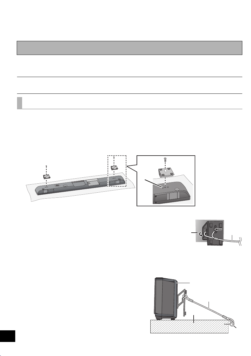
To prevent the unit from falling
1 On the rear of the unit:
Place the wall mount bracket by aligning the holes in the wall mount bracket
with the projecting parts A.
2 Screw the wall mount bracket firmly into place.
≥ Screw tightening torque: 80 N0cm to 120 N0cm.
≥ Repeat the steps above when installing the second wall mount bracket.
3 Thread a cord (not supplied) through each wall mount bracket.
≥ Make sure to use a cord which is capable
of supporting over 20 kg.
A Rear of this unit
B Fall prevention
cord
(not supplied)
4 After all the necessary connections are finished. (> 11)
Place the unit in the desired position and attach each cord onto the rack or
table.
≥ Attach each cord to a different screw eye.
≥ Make sure that there is no more than a 3 cm slack.
A This unit
10
B Fall prevention cord (not supplied)
C Rack or table
D Screw eye (not supplied)
≥ Attach at a position capable of supporting over
20 kg.
 Loading...