

Panasonic KX-TVS100 Installers Guide

Panasonic
Communication Systems Division
Technical Advisory
Updated: Nov. 16, 00
Subject: Quick KX-TVS100 Installation Guide
Document Number: KTVS1000001
AN I
NSTALLER’S GUIDE TO THE
KX-TVS100
V
OICE PROCESSING SYSTEMS
6.1

CHAPTER 1 STOP!
KNOW THE BASICS BEFORE GOING TO THE SITE
What the VPS Can and Cannot Do
System Basics
QUICK GUIDE TO THE KX-TVS100
T
ABLE OF CONTENTS
Why Voice Processing? 1.1
Basic Operations 1.1
VPS Limitations 1.2
System Components 1.2
Which Phone Systems are Compatible? 1.5
Installer Equipment and Software Requirements 1.6
Expansion Capabilities 1.6
Recommendations for System Configuration 1.6
Installing an Optional CO Card 1.7
CHAPTER 2 INSTALLATION
Safety Precautions
Installation 2.1
Wiring 2.1
Wall Mounting
On Wood 2.2
On Concrete or Mortar 2.3
Connections
Connecting PBX Extensions 2.4
Requirements for Connecting Programming Terminal 2.5
Connecting RS-232C Cable 2.6
EIA (RS-232C) Signals 2.7
Connecting the Power Cable to the VPS 2.8
CHAPTER 3 INTEGRATING THE VPS WITH THE PANASONIC
KX-TD DIGITAL PBX
Guidelines for Digital Integration
Why Digital Integration Is Important 3.1
Understanding How Digital Integration Works 3.1
6.2

Programming Instructions—Connecting the VPS with
the Panasonic KX-TD1232
KX-TD1232 Software Verification and Programming
for Digital Integration Via the Manager’s Extension 3.2
Voice Mail Port Assignment 3.3
Voice Mail Extension Number Assignment 3.3
Voice Mail Extension Group Assignment 3.4
Common Digital Integration Features and Setup
Procedures
Live Call Screening (LCS) Programming 3.5
Live Call Screening Recording Mode Assignment 3.5
Live Call Screening Private/Hands-Free Mode
Assignment 3.5
Live Call Screening Button Assignment 3.6
Live Call Cancel Button Assignment 3.6
Live Call Screening Password Assignment 3.6
Live Call Screening Password Canceling 3.7
Live Call Screening Password Control 3.7
Two-Way Recording into Mailbox 3.7
Two-Way Recording (TWR) Button Assignment 3.7
Two-Way Transfer into Mailbox 3.8
Two-Way Transfer (TWT) Button Assignment 3.8
KX-TD1232 Software Verification and Programming
Via the Operating and Maintenance Tool
Software Verification 3.9
System Programming 3.9
CHAPTER 4 INTEGRATING THE VPS WITH THE PBX
Guidelines for Integration
Why Integration is Important 4.1
Understanding How the VPS and the PBX Communicate 4.1
PBX Requirements for Integration 4.2
PBX Parameters and Port Settings:
General Guidelines and Definitions
RS-232C Settings 4.4
Port Settings 4.4
PBX Interface Parameters 4.4
Programming Instructions—Connecting the VPS with Panasonic KX-T Series PBXs
KX-TVS100 Software Verification and Programming 4.7
KX-T1232110 Software Verification and Programming 4.7
KX-T336 Software Verification and Programming 4.10
KX-TD1232 Software Verification and Programming
for Inband Integration 4.22
6.3

CHAPTER 5 DESIGNING THE SYSTEM
Starting Up
Start-up Sequence 5.1
Quick Setup 5.2
Port Setting Options
Custom Service (Recommended) 5.9
Sample Custom Service Message 5.9
Custom Service Tree 5.9
Custom Service Programming 5.10
Recording Menus 5.12
Checking Operation 5.12
Voice Mail 5.12
Interview Service 5.12
Automated Attendant 5.13
Setting Ports
Port Service Menu 5.13
Automated Attendant Parameters
Automated Attendant Menu 5.14
Department Dialing 5.14
Operator Parameters 5.14
Setting Mailboxes
Mailbox Setting Menu 5.15
Entering a Mailbox 5.15
Deleting a Mailbox 5.17
Password Reset 5.17
Mailbox Listing 5.17
CHAPTER 6 FINAL SETUP
Message Manager’s Mailbox
Accessing the Message Manager’s Mailbox 6.1
Message Manager’s Main Command Menu 6.1
Company Greetings 6.1
Modifying Voice Prompts 6.2
Recording the Company Name 6.12
Setting Up Mailboxes
Recording Personal Greetings 6.12
Recording the Owner’s Name 6.13
Backing Up the System 6.13
6.4

CHAPTER 1
S
!
TOP
WHAT THE VPS CAN AND CANNOT DO
KNOW THE BASICS
B
EFORE
OING TO THE SITE
G
W
HY VOICE PROCESSING
The VPS handles incoming and outgoing calls. When a call comes in, it answers, forwards to appropriate
extensions, takes and stores messages, and notifies subscribers when messages are left. Subscribers may send
and transfer messages to other subscribers within the system. The VPS is easy to use, helping callers through
the system with step-by-step voice prompts.
Unlike handwritten messages or those left with answering services, VPS messages are confidential; they are
stored in a mailbox and retrieved only with the subscriber’s password. Other advantages of the VPS are clarity
and accuracy, which are commonly lacking with written messages. The messages come directly from the caller,
in the caller’s own voice. To further ensure accuracy, the system allows the sender to correct or change
messages before saving them. Messages can be erased, transferred, or saved for future reference by the
recipient.
B
ASIC OPERATIONS
Greeting Callers: Callers are greeted by a prerecorded message that includes directions for leaving
?
and editing messages. The VPS can list single-digit numbers for each available
extension, mailbox, or department. Callers who know the extension of the person
they wish to reach may dial the extension number at any time. Callers with rotary
phones are transferred to a preprogrammed destination (which is often an operator
or the General Delivery Mailbox) to leave a message.
Sending Messages: Callers can review and edit messages before leaving them in a mailbox.
Subscribers can send messages to an individual or to several mailboxes at once.
The message sender can then verify that the message has been received by the
other subscriber.
Receiving Messages: Subscribers can choose from several different message notification methods.
They can be notified by: message waiting lamp, pager, or a call from the system
to another line. System programming determines whether a subscriber will be
notified each time a message is left. (Subscribers can choose to be notified of
messages differently depending on the time of day.) Mailbox parameters
determine maximum length and accommodate 5-100 messages. If the system is
connected using Digital Integration, subscribers can press a button to record
6.5
conversations in their own mailboxes or other subscribers’ mailboxes while
talking on the phone. Digital Integration also allows subscribers to screen
messages as they are being left and pick up if they choose to take the call.
VPS L
IMITATIONS
The KX-TVS100 does not support:
Fax-on-demand Some systems are connected to fax machines. Callers are offered the option of
leaving a fax number; the information is then automatically faxed to that number.
This system does not support this feature at this time.
UCD functions UCD (universal call distribution) is a service that distributes calls evenly among
extensions and returns to callers to say that all extensions are busy. This system
does not support UCD functions.
Integration with the wrong PBX or with certain Key Systems presents limitations to the TVS100’s
standard functions. We do not recommend these systems for integration with the TVS100. The section
Which Phone Systems Are Compatible? explains problems with compatibility.
SYSTEM BASICS
S
YSTEM COMPONENTS
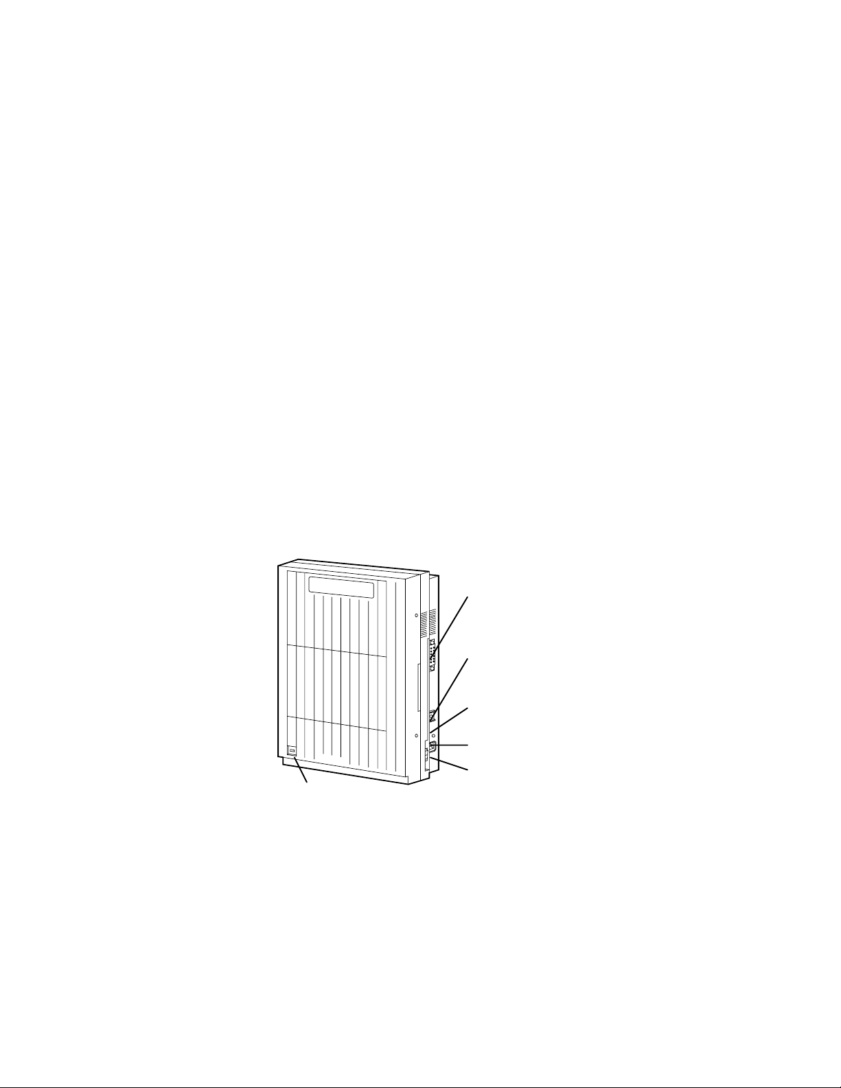
TVS100
VOICE PROCESSING SYSTEM
Panasonic
Power Indicator
Main Cabinet
EIA (RS-232C)
Connector
Ground
Terminal
Fuse
AC Inlet
Power Switch
6.6
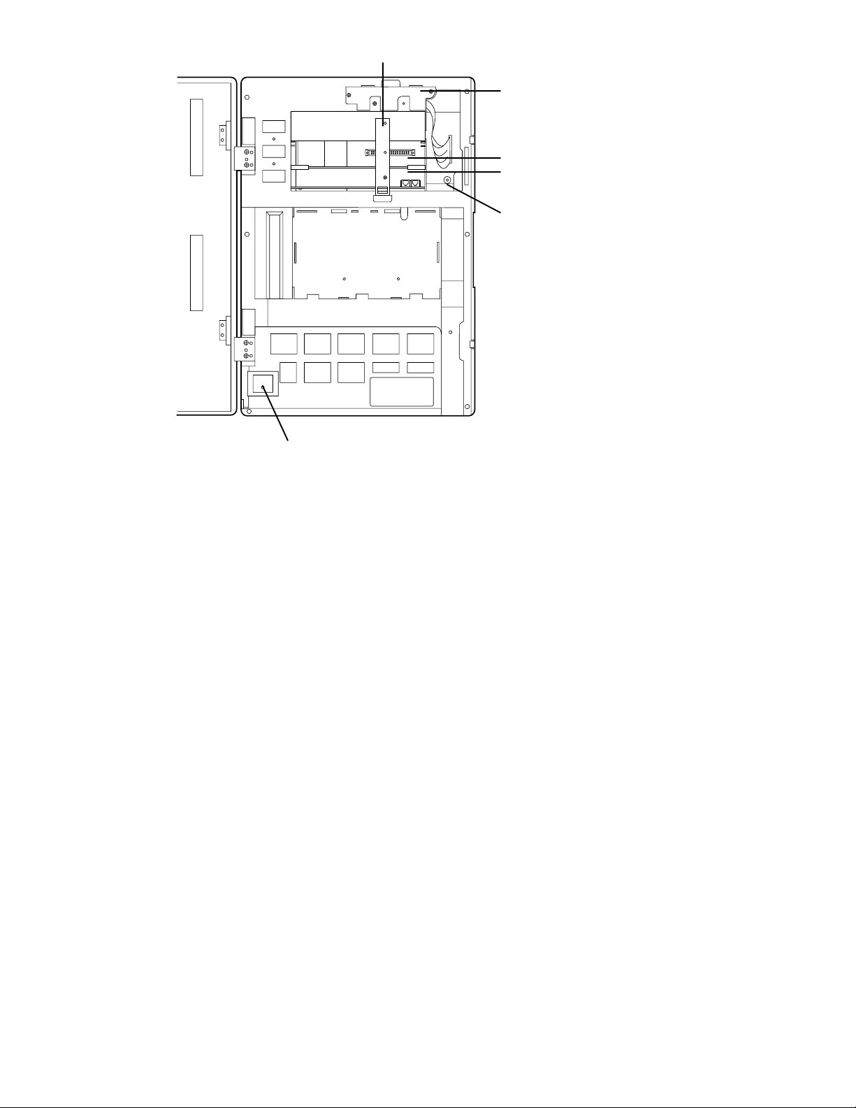
SLOT 3
Grounding Strap
Hard Disk Drive
SLOT 2
SLOT 1
POWER
Power Indicator
Inside View of the Main Cabinet
Slot for Optional CO Card
CO Card
Rotary Switch
AC Power Jack Connects the power cable to an AC outlet dedicated for
the VPS.
Power Indicator Indicates system status—when flashing, the system is off-line (not ready to
receive calls).
Power Switch Starts the system and begins the self test.
SAFETY PRECAUTION: When making any connections or removing the
cover, be sure the power switch is turned off.
Ground Terminal This terminal should be connected to a ground source with less than 1 ohm
resistance.
Fuse (700mA 250v) Protects the system from power line surges and should only be replaced with the
same type.
6.7

CO Card KX-TVS102
(1-2/system) Includes the telephone line interface and the CODEC facility. The
telephone line interface transmits and receives analog and digital signals (when
used with KX-TD D-PITS extensions to and from the Voice Mail ports). The
analog signal is digitized at a sampling rate of 8 kHz to create an 8-bit digital
signal. The CODEC facility consists of two digital signal processors (DSP).
When a user calls the VPS, one of the DSPs compresses the digital signal sent
from the telephone interface. This compressed signal is stored on the hard disk as
data. When messages are played back, the DSP decompresses the stored data and
the signal is then sent back to the telephone interface. Each card supports two
ports. (The number of ports determines how many users can simultaneously
access the VPS.)
CPU Card (1/system) Main processing unit for the system; comprised of: central
microprocessor, ROM, dynamic RAM, system controller, rotary switch, and an
RS-232C interface.
EIA Connector RS-232C
Connects an ASCII or VT terminal to the VPS; must be used to program system.
Hard Disk Drive (1/system) Stores the proprietary system program, the system administration
table, and the voice prompts (about 40 minutes worth); has the capacity to record
approximately four hours of messages from callers. (The hard disk is controlled
by the central microprocessor.)
Grounding Strap Protects the printed circuit board from static electricity.
(Ground) SAFETY PRECAUTION: Discharge any body static by touching the
metal board.
Rotary Switch (Check the status of this switch only at start-up.)
Provides the following additional functions:
Position Additional Function
0 Normal setting.
1 Initializes RS-232C parameters.
RS-232 default parameters: 9,600, N, 8, 1
2* Quick Setup is automatically completed and all
ports are set for Automated Attendant service.
3* Quick Setup is automatically completed and all
ports are set for Voice Mail service.
4 Reserved for future function.
5 Initializes the VPS. Clears all messages and
data.
6-9 Reserved for future function.
* For Panasonic KX-TD series telephone systems with
D-PITS Integration
6.8

W
HICH PHONE SYSTEMS ARE COMPATIBLE
?
We recommend integration with the following Panasonic phone systems:
Panasonic KX-TD1232
Panasonic KX-TD816
Panasonic KX-T336
Panasonic KX-T123211D
We cannot guarantee adequate integration of the TVS100 with other PBX systems or with Key Systems. If
the customer does not have one of the recommended Panasonic PBX systems, be sure that the system has the
features listed in the following section.
The PBX must have the following features for successful integration:
• Single line (tip/ring) port circuits
(Some PBXs need an OPX card to provide this connection. See page 4.2 for more details and
minimum current and voltages that the PBX must supply.)
• Station to station DTMF signaling
• Message waiting notification from an SLT (single-line telephone)
• Screened transfer from an SLT
If the PBX does not have these features, VPS operation will be limited.
Please see Chapter 4 under the heading: PBX Requirements for Integration. For each of the features
above, this section gives the following information:
• Description
• Limitations of the system without the feature
• Tests to determine whether the PBX has the feature
Avoid Voice Mail Jail!
The recommended Panasonic PBX systems have Follow-on ID and Inband Integration. When callers are
transferred to an extension that is forwarded to Voice Mail, Follow-on-ID sends callers directly to the
mailbox. Without Follow-on ID, the caller would have to re-enter the desired mailbox number when
connected to the Voice Mail.
DTMF Integration enables the VPS to recognize the current state of the call and improve its call handling
performance. When enabled, the PBX informs the VPS of the status of the call (busy, answered, ringing,
etc.) by sending a code with DTMF tones before sending the normal call progress tones. For example,
when a caller hangs up before making a selection, the PBX sends # 9 to the VPS port that answered. This
informs the VPS that the caller has hung up. Upon receiving these digits, the VPS goes on-hook and is
ready to handle another call.
Digital (D-PITS) Integration is available when the VPS is connected to a Panasonic KX-TD series PBX
(depending on the software version). This digital integration provides the VPS with more information than
DTMF integration. This information enables the system to identify the extension number of the caller,
know where the call is forwarded from and why, and recognize what the caller wants to do. Some features
are available only with D-PITS integration (Live Call Screening, Two-Way Recording, Direct Mailbox
Access, Intercom Paging, Auto Configuring).
I
NSTALLER EQUIPMENT AND SOFTWARE REQUIREMENTS
6.9

The installer must have a laptop computer or data terminal equipped with terminal emulation software. We
recommend Procom Plus
®,
version 2.0 or higher. The computer is used to program the VPS. Terminal
emulation software enables the keyboard to be used as a data entry device. The data terminal or terminal
emulation software must support ASCII or VT100 type terminals. It is best to use a VT100 type terminal to
program the system.
While both the laptop and data terminal will work, the laptop allows screens to be saved in a file throughout the
process. It is often helpful to retrieve these files later if technical support is needed.
E
XPANSION CAPABILITIES
Standard System: 2 ports, 1 CO card
The VPS comes equipped with 2 ports. Each port represents one extension on the phone system. Expansion
requires an additional CO card (KX-TVS102). With 2 ports, the VPS can handle 2 simultaneous calls; it can be
expanded to 4 ports (to handle 4 simultaneous calls). Because each CO card has 2 ports, ports are increased in
increments of 2.
Ports:
extensions connected to VPS (2 ports—standard)
extensions connected to VPS (4 ports—maximum)
Voice Storage:
The standard KX-TVS100 can store up to 4 hours; this cannot be expanded.
R
ECOMMENDATIONS FOR SYSTEM CONFIGURATION
General guideline: a ratio of 6/1 (for every 6 lines, 1 CO board). There are two questions to ask when
considering how many CO boards:
1. Are the ports answering all incoming calls or just forwarded/transferred calls?
2. If they are answering incoming calls, how busy are the lines?
The guideline above (6/1) usually works well with moderate traffic. This may have to be modified for heavy
traffic. These recommendations are outlined in the chart below.
Recommendations for Voice Mail Ports
1 CO board may not support an Automated Attendant configuration with 5 CO lines. The following
recommendations for Automated Attendant ports may have to be modified for heavy traffic.
Recommendations for Automated Attendant Ports
I
NSTALLING AN OPTIONAL
CO C
ARD
Safety Precautions:
1. Make sure that the power switch is turned off.
6.10
2. Discharge any body static by touching the grounding strap.
(This protects the printed circuit board from static electricity.)
3. Refer to the manual for the optional CO card for further precautions
and installation procedures.
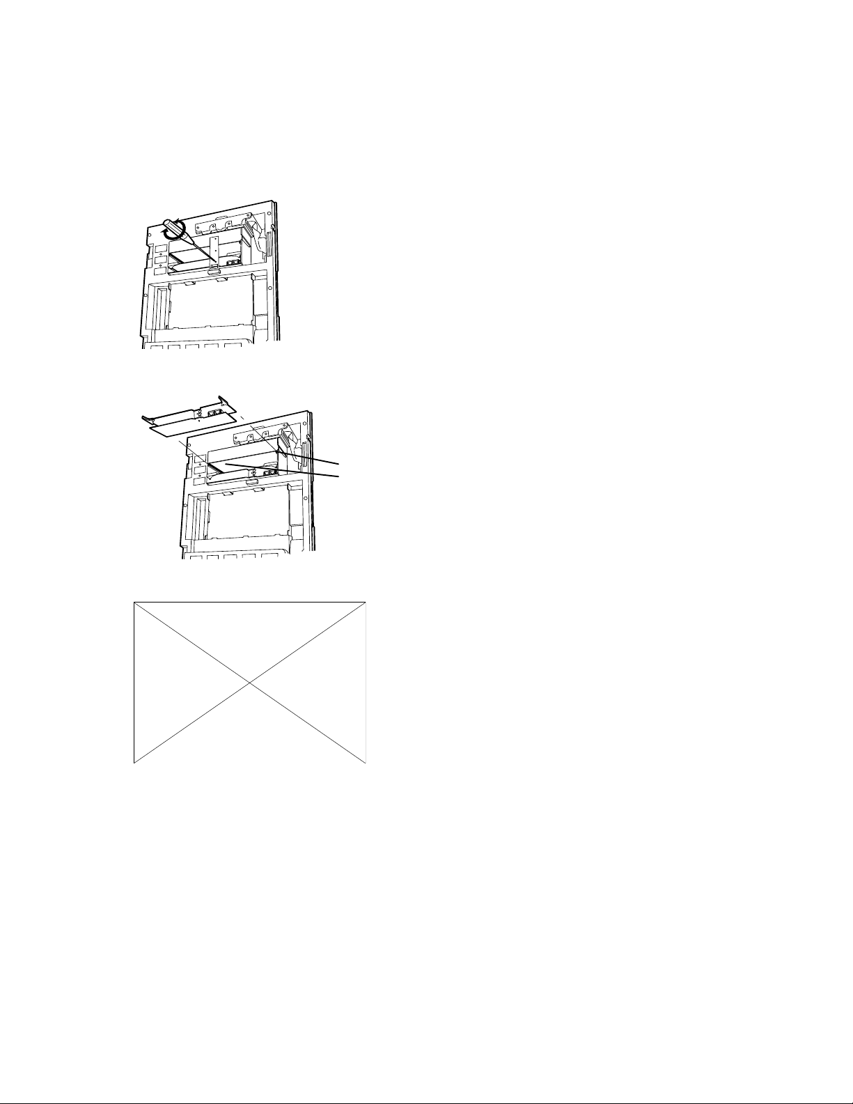
1. Loosen the screw on the grounding strap. Then remove the strap from the unit.
SLOT 3
SLOT 2
SLOT 1
2. Insert the optional CO card, along the guide rails, into SLOT 2.
SLOT 3
SLOT 2
SLOT 1
Guide Rail
3. Press the left and right card latches firmly, then affix the grounding strap to the unit with a screwdriver.
6.11

6.12

6.13

CHAPTER 2
NSTALLATION
I
SAFETY PRECAUTIONS
Please read the following precautions before installing the VPS.
I
NSTALLATION
The VPS can be installed on the floor or on the wall. Improper placement of the system may result in
malfunction, noise, or discoloration. Avoid installing the VPS in the following places:
• in direct sunlight; in hot, cold, or humid places.
• in new areas where there are thermal springs, etc. (where sulfuric gas may
damage the equipment or contacts).
• where shocks or vibrations are frequent or strong.
• in dusty places or places where water or oil may come in contact with the unit.
• near high frequency generating devices such as sewing machines, elevators or electric welders.
• on or near computers, telexes, or other office equipment; near microwave ovens or air
conditioners. (Ideally, the VPS should not be in the room with these items and should be at least 6
feet away from televisions.)
Do not obstruct the areas around the PBX and the VPS. Both require space above for cooling and space
on the sides for maintenance and inspection.
W
IRING
• Do not wire the telephone cable parallel to an AC power source, computer, telex, etc. If cables are run
near those wires, shield the cables with metal tubing or use shielded cables and ground the shields.
• Use protectors if running cables on the floor; avoid wiring under carpets.
• Avoid sharing a 120 V AC power supply for computers, telexes, and other office equipment with the
VPS. Induction noise from that equipment may interrupt the VPS operation.
When making any connections or removing the cover, be sure the power switch is turned off.
WALL MOUNTING
6.14
The VPS can be installed on the floor or on the wall. If mounting on the wall, be sure that the wall can support
the weight of the VPS. Use the screws supplied with the system or use screws that are the same in diameter.
ON W
OOD
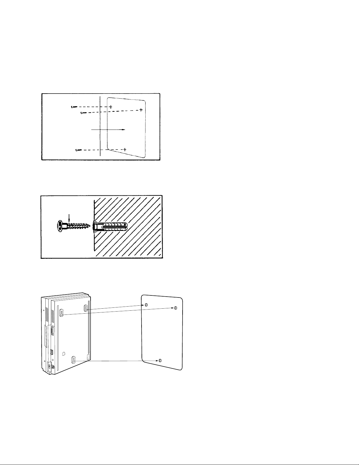
1. Place the template (included) on the wall to mark the three screw positions.
Template
2. Install three screws.
Drive the screw to
this position.
3. Hook the unit onto the screw heads.
ON C
ONCRETE OR MORTAR
1. Place the template (included) on the wall to mark the three screw positions.
6.15
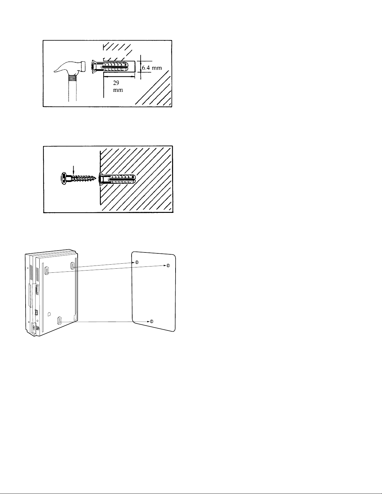
2. Drill three holes and hammer in anchor plugs until they are flush with the wall.
To Wall Surface
Anchor Plug
1 1/8 inch
Concrete
Wall
1/4 inch
3. Install three screws into the anchor plugs.
Drive the screw to
this position.
4. Hook the unit onto the screw heads.
6.16
CONNECTIONS
g
g
C
ONNECTING
PBX E
XTENSIONS
The VPS must be connected to the PBX extensions before starting the system. Up to four extensions can be
connected to the VPS. Each PBX extension is inserted into the modular jack on the CO card.
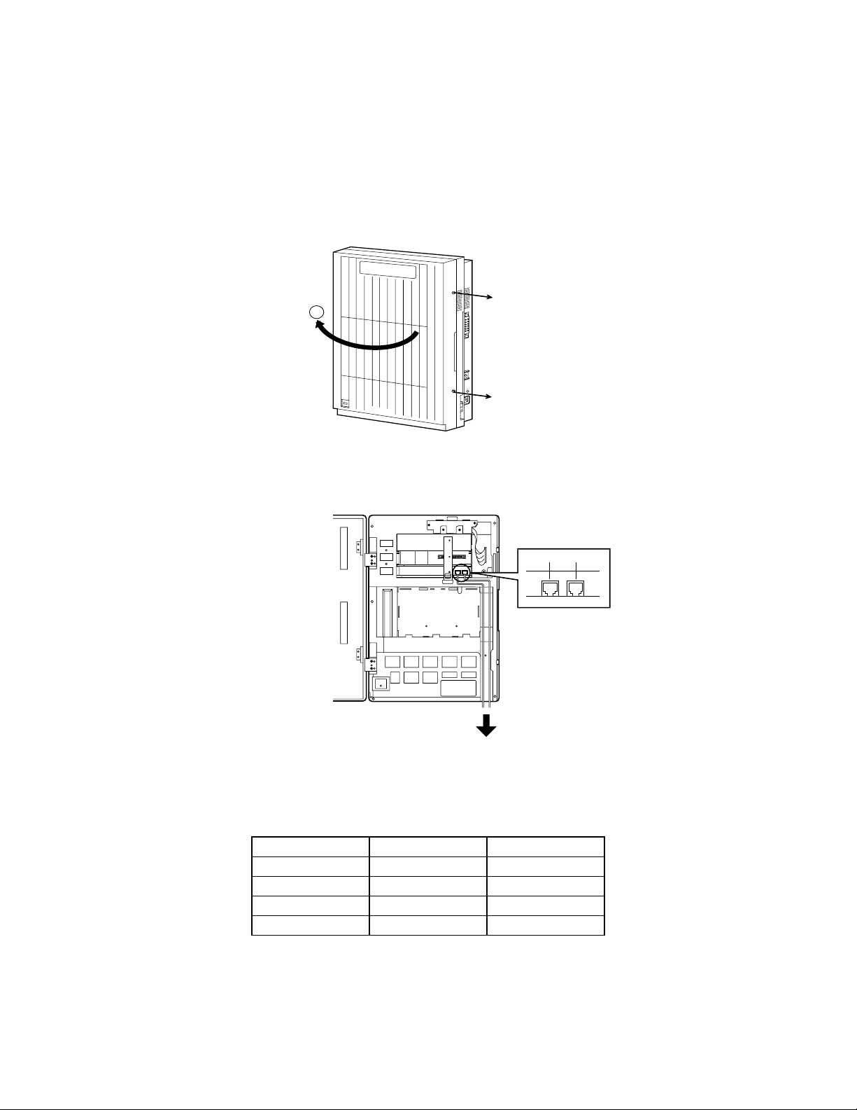
1. Loosen the two screws on the right side of the main unit, then open the front cover (A).
TVS100
VOICE PROCESSING SYSTEM
screw
A
Panasonic
screw
2. Insert modular plug of the PBX extension into modular jack on the CO card.
telephone line
SLOT 3
SLOT 2
SLOT 1
modular jacks
PORT 1 PORT 2
POWER
to the extension
port of the PBX
Make sure the PBX extension is connected to the proper modular jack. Modular jacks on the CO card
correspond to the port numbers as follows:
CO Card Modular Jack Port Number
1Left1
1Ri
ht 2
2Left3
2Ri
ht 4
Assign one of the incoming call services according to the port number.
6.17
To use D-PITS Integration, Port 1 of the VPS must be connected to the lowest number jack assigned as a
VPS extension. When D-PITS Integration is activated, a single extension jack provides two single-line
interfaces to the CO card on the VPS. For example, only connect one line cord (4 wire) to Port 1 on the
VPS. This will provide two extensions. Then connect the second line cord (4 wire) to Port 3 (if installed)
for the other two extensions. Only one D-PITS (4 wire) extension can be connected per card.
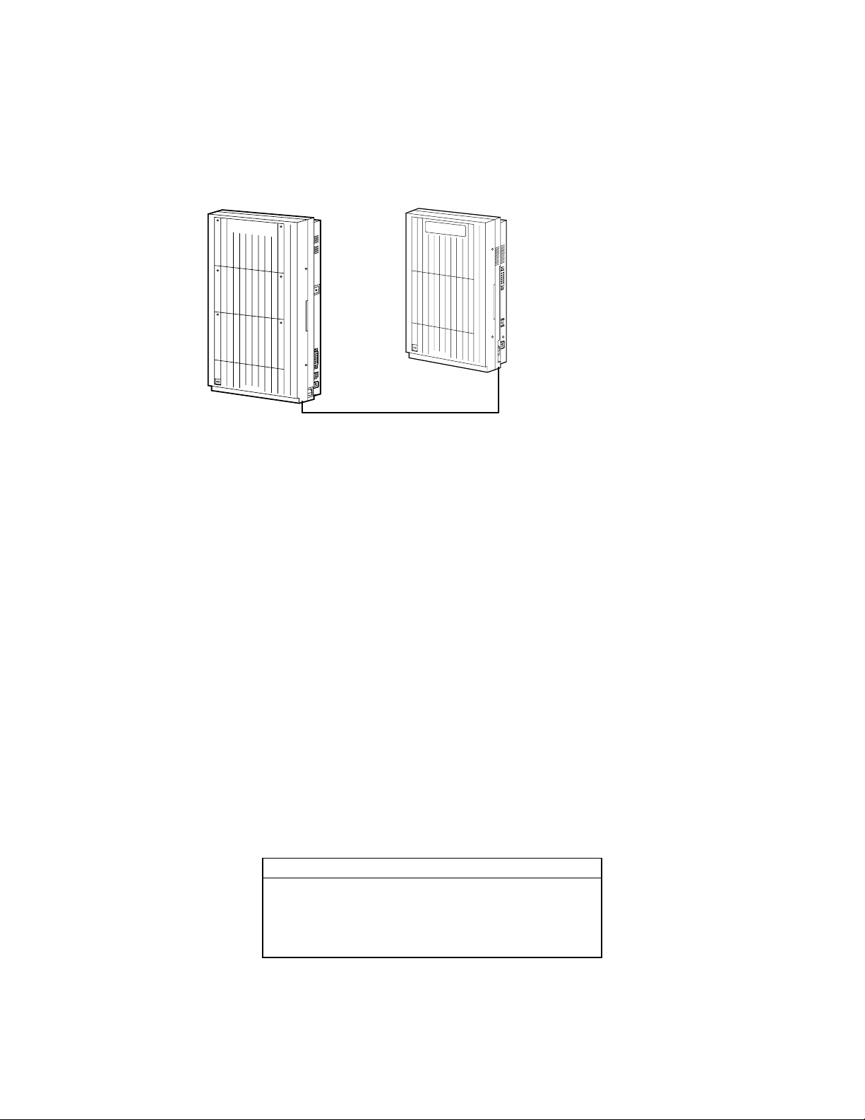
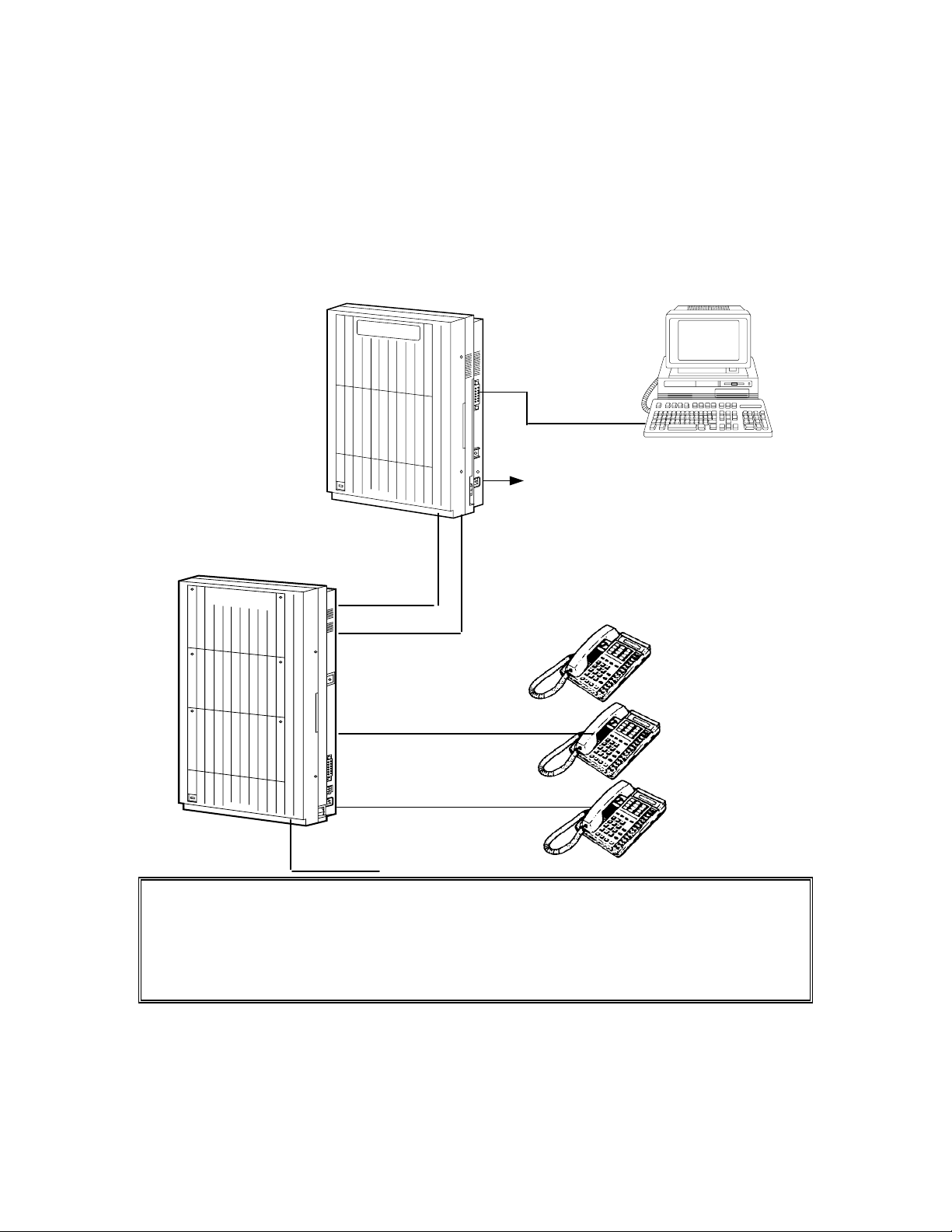
3. Connect the PBX extension to the CO ports of the Voice Processing System.
Your PBX VPS
D1232
DIGITAL SUPER HYBRID SYSTEM
Panasonic
TVS100
VOICE PROCESSING SYSTEM
Panasonic
Follow instructions on the PBX to connect the PBX extension ports to the CO ports on the VPS. Use a
four-conductor wiring cord for connection with KX-TD systems that use D-PITS integration. Use a twoconductor wiring cord for connections to all other PBXs. The maximum length of the wire varies
according to the PBX length. (Refer to the PBX installation manual for length.) Write down the extension
port number of the PBX extensions that are connected to the TVS100. You will need to know these
numbers when accessing the TVS100.
4. Close the front cover of the VPS (and the PBX if the cover was removed).
5. Tighten the two screws firmly.
R
EQUIREMENTS FOR CONNECTING PROGRAMMING TERMINAL
The programming terminal must be connected with a serial cable with an RS-232C connector at the EIA port.
This enables system administration (system set-up, mailbox set-up, and system diagnosis). If the DEC VT220
(100) or VT220 (100) compatible terminal is used, the system administrator can set up system parameters and
diagnose the system with the menu-driven program. Other RS-232C ASCII terminals can also be used, but we
recommend a terminal that supports VT emulation. The wiring and parameters are the same for either terminal
type.
Communication parameters of the VPS have been set to the following values at the factory:
COMMUNICATION PARAMETERS
Baud Rate: 9600 bps
Word Bit Length: 8 Bits
Parity: None
Stop Bit Length: 1 Bit
C
ONNECTING
RS-232C C
ABLE
6.18
STOP: Before connecting the cable, make sure the power switches on both the data
terminal and the VPS are OFF.
TVS100
VOICE PROCESSING SYSTEM
RS-232C Cable
Data Terminal
or Printer
Panasonic
EIA Port (RS-232C)
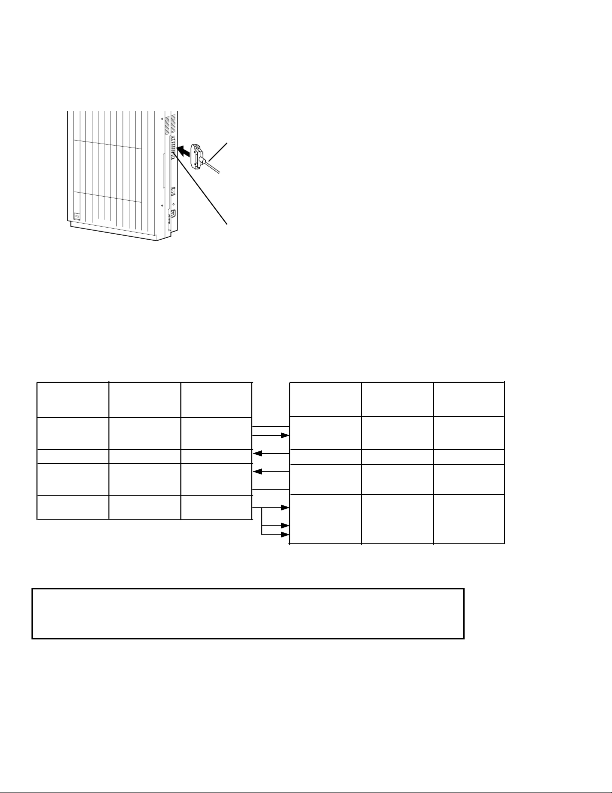
Insert the RS-232C cable into the VPS with the connector indicating the same direction.
Programming Terminal Connection
Connect the terminal and KX-TVS100 cables as shown in the chart below. Cables must be shielded and no
longer than 6.5 feet.
TVS100 Data Terminal
Circuit Type
(EIA)
AA
BA
BB
CC
AB
CD
Signal
Name
FG
TXD
RXD
DSR
SG
DTR
Pin
No.
1
2
3
6
7
20
Pin
No.
1
3
2
20
7
5
6
8
Signal
Name
FG
RXD
TXD
DTR
SG
CTS
DSR
DCD
Circuit Type
(EIA)
AA
BB
BA
CD
AB
CB
CC
CF
Sub-part J of Part 15 of FCC Rules requires special accessories, such as cable, to
comply with Class A computing devices. Accessories specified in this installation
manual meet this requirement.
6.19

EIA (RS-232C) S
IGNALS
Frame Ground (FG)
Connects to the unit frame an external ground, usually the ground pin of the AC power cord.
Transmitted Data (TXD)—output
Conveys signals from the unit to the terminal/printer. A “mark” condition is held unless data or BREAK
signals are being transmitted.
Received Data (RXD)—input
Conveys signals from the terminal/printer to the unit.
Request To Send (RTS)—output
Sets the modem to originate so that it can send; this lead is held on whenever DSR
is on.
Clear To Send (CTS)—input
When circuit CTS is on, the terminal/printer is ready to receive data from the unit. The unit does not
attempt to transfer data or receive data when circuit CTS is off.
Data Set Ready (DSR)—input
When circuit DSR is on, the terminal/printer is ready. Circuit DSR ON does not indicate that
communication has been established with the terminal/printer.
Signal Ground (SG)
Connects to the DC ground of the unit for all interface signals.
Data Terminal Ready (DTR)—output
This signal line is turned on by the unit to indicate that it is on line. Circuit DTR ON does not indicate that
communication has been established with the terminal/printer. It is switched off when the unit is off-line.
Data Carrier Detect (DCD)—input
The DCD is on when the carrier signal is being received.
6.20
C
ONNECTING THE POWER CABLE TO THE
VPS
Before connecting the power cable to an AC outlet, make sure all other connections
(RS-232C data terminal with VPS, PBX with VPS, PBX with PBX extensions) are secure. Use an AC outlet
dedicated for the VPS unit.
TVS100
VOICE PROCESSING SYSTEM
RS-232C
Interface
Data Terminal
D1232
DIGITAL SUPER HYBRID SYSTEM
Panasonic
CO 01
Panasonic
Port 1
EXT. 101
EXT. 102
EXT. 103
EXT. 104
EXT. 105
To AC Outlet
Port 2
Operator
(Message
Manager)
CHAPTER 3
I
NTEGRATING THE
P
ANASONIC
KX-TD D
GUIDELINES FOR DIGITAL INTEGRATION
W
HY DIGITAL INTEGRATION IS IMPORTANT
VPS
IGITAL
WITH THE
PBX
6.21
The KX-TVS100 works well with most PBXs because its connections are made through a standard single line
6
(tip/ring) telephone interface. However, the communication between the PBX and VPS is best when Digital
Integration is used; the KX-TVS100 is already set up to communicate through Digital Integration.
U
NDERSTANDING HOW DIGITAL INTEGRATION WORKS
To the Panasonic KX-TD digital PBX, the VPS ports look like digital extensions. The PBX thinks that the VPS
is a digital phone, and the VPS mimics all actions of a digital set. Another advantage of Digital Integration is
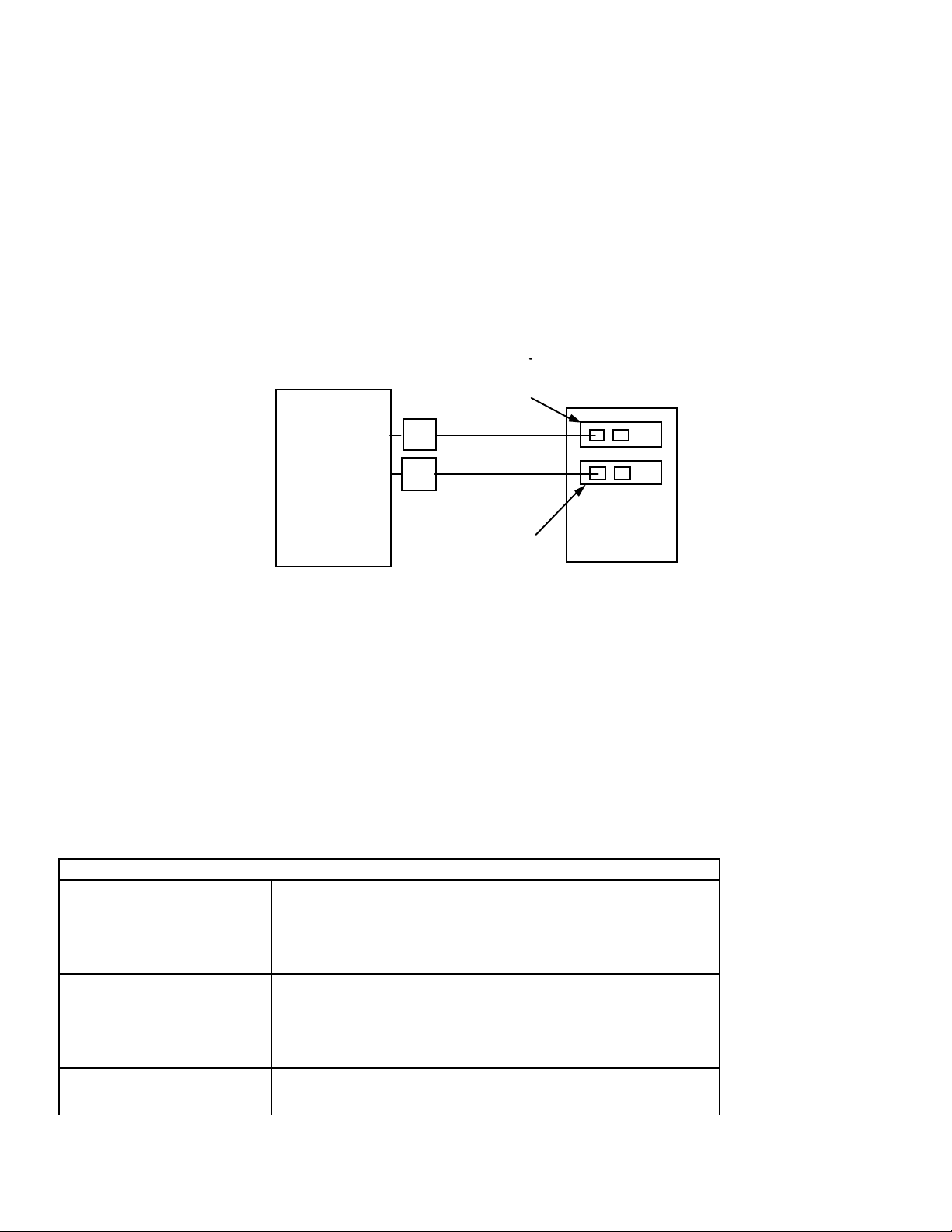
that the 2B+D communication provides two Voice Mail ports for each Digital Station port. For example, you
can connect jack 15 of the KX-TD1232 to Port 1 of the Voice Mail with a four-wire connection (see diagram
below). This connection creates two Voice Mail extensions and can simultaneously answer two calls. This
means that a fully-configured four-port system requires only two jacks from
the PBX.
port 2
extensions 167 and 168
KX-TD1232
16
15
KX-TVS100
port 1
extensions 165 and 1
Fig. 1
Communication between the VPS and the PBX through Digital Integration requires the proper software level in
the PBX and four-wire connections for each port. Also, the PBX and VPS must be programmed to work with
each other.
Once Digital Integration is established, the PBX sends information to the VPS through the data link. This
information enables the VPS to identify the extension that is calling, know where a call is forwarded and why
it’s forwarded, and recognize what a caller wants to do. This communication allows features that are only
available with Digital Integration, several of which are described below.
DIGITAL INTEGRATION FEATURES
Auto Configuration The VPS knows what extension numbers exist on the PBX and
creates mailboxes for each extension automatically.
Live Call Screening Extension users can monitor messages as they are being left in the
mailbox and intercept if required.
Two-Way Recording Extension users can record conversations in their own mailboxes by
pressing one button.
Direct Mailbox Access The VPS asks the caller for the password; the caller does not have to
dial the mailbox number.
Intercom Paging Callers can page subscribers through built-in speakers and external
paging equipment.
6.22

The KX-TVS100 System comes from the factory already set up for a KX-TD1232 PBX. When the power is
turned on for the first time, the VPS will try to communicate with the KX-TD1232 through Digital Integration.
For this reason, several things should be done before starting up the KX-TVS100 for the first time.
PROGRAMMING INSTRUCTIONS—CONNECTING THE VPS WITH THE
PANASONIC KX-TD1232
KX-TD1232 S
D
FOR
IGITAL INTEGRATION VIA THE MANAGER’S EXTENSION
OFTWARE VERIFICATION AND PROGRAMMING
It is important that the KX-TD1232 have the proper software level to allow Digital Integration with the VPS.
Follow the procedures below to confirm the software level,
then complete the required programming before starting up the VPS.
NOTE: Two methods of programming are available on the KX-TD1232. The instructions below show how to
program without the operating and maintenance tool. For instructions on programming with the operating and
maintenance tool, please see page 3.9.
All of the following procedures must be done after entering system programming. Refer to the KXTD1232 Installation Manual for
instructions on how to enter the system programming mode.
Step 1
Check the software version of the KX-TD1232 by using PITS programming code 116, which shows the
software version number: P101A 50508B
The underlined digits represent the software production date code (format YMMDD). In this example,
the date code is May 8, 1995 (year, month, day). For Digital Integration, the software production date
of the PBX must be March 31, 1995, or later. If the software production date of the PBX is earlier
than this, call Panasonic Parts Center (MSC) about an upgrade: 1-800-833-9626.
6.23

Step 2
From the System-Prg No. ? screen:
1. Enter [116].
2. Press the NEXT button (sp-phone).
3. Enter the system number ([0] or [1], master/slave).
The system displays the ROM version and date it was created.
This version must be P101A with a date of 05-08-95 or later for Digital Integration to be utilized
(both systems if system connection is used).
V
OICE MAIL PORT ASSIGNMENT
This program tells the PBX which jacks will be connected to the Voice Mail system. This allows the PBX to
send the proper Digital Integration information to those ports.
From the System-Prg No. ? screen:
1. Enter [117].
2. Press the NEXT button (Sp-Phone).
Screen Output: Master: # # #
3. Enter the jack number of the first port you will use
for the Voice Mail (02 - 64).
4. Press [→] to enter the next jack number.
5. Enter the second jack to be used for Voice Mail.
6. Repeat Steps 4 and 5 until all jacks are entered.
7. Press STORE.
8. Press the NEXT button to program the slave system (if connected).
9. Press END (Hold) when finished.
Conditions: Jack 01 cannot be used as a Voice Mail port. A jack programmed as a Manager
Extension (prg. 006) cannot be used in this program. The jack numbers correspond to Voice Mail port
numbers in numerical order. The lowest jack entered here must be connected to the first port of the
VPS.
Example: Jack 02 = Voice Mail numbers 01, 02; Jack 03 = 03, 04
(Each jack entered gives two Voice Mail ports.)
V
OICE MAIL EXTENSION NUMBER ASSIGNMENT
This program allows you to assign an extension number to each Voice Mail port. Since each jack connected to
the VPS provides two extensions, this enables you to assign extension numbers to each port. You can assign any
extension number that is not already assigned to another port. To reach the Voice Mail system, users dial these
extension numbers. It is not necessary to change the default programming for the extensions 165, 166, 167,
168.
From the System-Prg No. ? screen:
1. Enter [118].
2. Press the NEXT button (Sp-Phone).
Screen Output: VM NO? →
3. Press the NEXT button (Sp-Phone).
Screen Output: VM-01:#_ _ -1: 165
( _ _ = the first port number you entered in program 117).
6.24

4. Enter the extension number that you want this port to have. (The default extension number for
port 1: 165; port 2: 166 ...)
5. Press STORE.
6. Repeat Steps 3, 4, and 5 until all extension numbers are entered.
Conditions: No two jacks on the system can have the same extension number. If you try to enter a
number that is already assigned, you will hear an error tone. Each digital extension connected provides
two Voice Mail ports and must have two different extension numbers assigned.
V
OICE MAIL EXTENSION GROUP ASSIGNMENT
This program allows you to assign an extension group number to each Voice Mail port. The default
programming for all ports is Group 01. The group assigned should be used only for ports connected to the
Voice Mail. It is not necessary to change the default programming for Voice Mail extension group assignments
for most applications.
From the System-Prg No. ? screen:
1. Enter [119].
2. Press the NEXT button (Sp-Phone).
Screen Output: VM EXG Group Assn.
3. Press the NEXT button (Sp-Phone).
Screen Output: VM No?
4. Enter the extension group number that you want the first Voice Mail port
to be in.
5. Press STORE.
6. Repeat Steps 3, 4, and 5 until all Voice Mail ports are assigned a group.
7. Press END (Hold).
The required programming is complete and the VPS and KX-TD1232 should be able to
communicate through Digital Integration.
We recommend that the KX-TD1232 system have any optional extension cards and
telephones connected before starting the VPS.
When running the Quick Setup command (Chapter 5) from the VPS, the PBX transmits
the station information automatically. This saves time when programming the VPS.
6.25

COMMON DIGITAL INTEGRATION FEATURES AND SETUP PROCEDURES
L
IVE CALL SCREENING
(LCS) P
ROGRAMMING
LCS notifies subscribers of incoming messages to their mailboxes. The notification method is programmable
for hands-free or private. Hands-free allows the user to monitor a recording through the speaker-phone and, if
desired, intercept the call by lifting the handset. The private mode notifies the user with an alert tone when a
message is being recorded. By pressing the LCS button, the user can monitor the message and intercept the call
by going off-hook. Programming also determines whether the mailbox continues to record after the user
intercepts the call.
L
IVE CALL SCREENING RECORDING MODE ASSIGNMENT
This program allows the VPS to continue recording the conversation in the mailbox after the extension
intercepts the call during the Live Call Screening.
1. Enter [610].
2. Press the NEXT button (sp-phone).
Screen Output: Jack No.?
3. Enter the jack number.
Screen Output: # _ _ Stop Recording
(_ _ = the jack number you entered)
4. Press the SELECT button (Auto-Ans) until the desired selection is displayed.
5. Press STORE.
6. Press the NEXT button (Sp-Phone).
7. Repeat Steps 4, 5, and 6 until all jacks are programmed.
Conditions: Only available with D-PITS Integration.
L
IVE CALL SCREENING PRIVATE/HANDS-FREE MODE ASSIGNMENT
This program assigns a VPS response for when a message is being left in a mailbox. It determines whether an
alert tone is sent and whether the recorded message is played through the built-in speaker of the extension. The
default mode is hands-free. (This is a station level program and should be done at each individual phone.)
1. Enter PITS programming:
a. With the phone on-hook, press the PROGRAM button.
b. Dial [99]. (Display changes to PT-Prg Mode.)
2. Dial the code for the mode you want this phone to have.
Hands-Free = 71
Private = 72
Screen Output: Hands-Free or Private
3. Press STORE.
4. Exit the program mode by pressing the PROGRAM button.
5. Repeat these steps at each telephone.
Conditions: None.
6.26

L
IVE CALL SCREENING BUTTON ASSIGNMENT
For the Live Call Screening feature to work at an extension, the extension must have an LCS button on it and
the button must be lit at the time of the message. This key must be either a DSS/BLF or CO key (must have a
lamp). Follow the procedure below to assign an LCS button on an extension. (This is a station level program
and should be done at each individual phone.)
1. Enter PITS programming:
a. With the phone on-hook, press the PROGRAM button.
b. Dial [99]. (Display changes to PT-Prg Mode.)
2. Press the desired FLEXIBLE (CO or DSS/BLF) button you want to assign
as the LCS button.
3. Dial [92].
Screen Output: LCS
4. Press STORE.
5. Repeat these steps at each telephone.
6. To exit the Station Programming mode, press the PROGRAM button
or lift the handset.
7. Repeat these steps for each telephone.
Conditions: This button must be assigned and lit for LCS to operate. To light this, press the button
and dial the LCS password (see Password Assignment).
L
IVE CALL SCREENING CANCEL BUTTON ASSIGNMENT
This button assignment allows you to assign a Flexible (CO, DSS) button as a Live Call Screening Cancel
button. (Before setting, be sure that you are in the Station Programming mode; press [PROGRAM 99]).
1. Press the Flexible (CO, DSS) button that you wish to assign
as a Live Call Screening Cancel button.
2. Dial [93].
Screen Output: LCS Cancel
3. Press STORE.
The STORE indicator light turns on.
The display shows the initial programming mode.
4. To exit the Station Programming mode, press the PROGRAM button
or lift the handset.
The Live Call Screening Cancel Button Assignment is optional; Live Call Screening can also be
canceled by pressing the FLASH button.
L
IVE CALL SCREENING PASSWORD ASSIGNMENT
To allow the Live Call Screening feature to work at an extension, the extension must have the LCS button lit.
To light this button on the phone, press the LCS button, then enter the password. This password prevents others
from activating the LCS feature and listening to the messages as they are being left. (It is not necessary to enter
PITS Programming to activate this feature.)
1. Lift the handset or press the speaker-phone button.
2. Dial the feature number [799].
6.27

3. Dial any password of three digits ([000] - [999]) twice.
You will hear a confirmation tone, then a dialtone.
Screen Output: The three-digit password you entered is displayed.
L
IVE CALL SCREENING PASSWORD CANCELING
To cancel the password, follow the procedure below. (It is not necessary to enter PITS Programming to activate
this feature).
1. Lift the handset or press the speaker-phone button.
2. Dial the feature number [799].
3. Dial the password ([000] - [999]).
You will hear confirmation tone, then a dialtone.
Screen Output: Password Canceled.
L
IVE CALL SCREENING PASSWORD CONTROL
This feature allows Operator 1 to cancel the password for LCS at any extension. If a user forgets the preprogrammed password, Operator 1 can cancel the LCS password.
1. Enter PITS programming:
a. With the phone on-hook, press the PROGRAM button.
b. Dial [99]. (Display changes to PT-Prg Mode.)
2. Dial [*].
Screen Output: Ext No?
3. Dial the extension number or [*] key to remove all passwords.
4. Press STORE.
5. To exit the Station Programming mode, press the PROGRAM button
or lift the handset.
TWO-W
AY RECORDING INTO MAILBOX
This feature allows extension users to record conversations into their mailboxes by pressing the Two-Way
Recording (TWR) button.
TWO-W
AY RECORDING
(TWR) B
UTTON ASSIGNMENT
For the Two-Way Recording feature to work at an extension, the extension must have a TWR button on it. This
key must be either a DSS/BLF or CO key (must have a lamp). Follow the procedure below to assign a TWR
button on an extension. (This is a station level program and should be done at each individual phone.)
1. Enter PITS programming:
a. With the phone on-hook, press the PROGRAM button.
b. Dial [99]. (Display changes to PT-Prg Mode.)
2. Press the FLEXIBLE button (CO or DSS/BLF) that you want to assign
as the TWR button.
3. Dial [90].
Screen Output: 2 Way-Rec.:
4. Enter a Voice Mail extension number.
Screen Output: 2 Way-Rec: _ _ _
(_ _ _ = The extension number you entered).
5. Press STORE.
6.28
 Loading...