

Page 1

Voice Processing System
POWER
VOICE PROCESSING SYSTEM KX-TVP50
Installation Manual
Model No.
KX-TVP50
Thank you for purchasing a Panasonic Voice Processing System, Model KX-TVP50.
Please read this manual before installing, customising, or operating the Voice Processing System.
Page 2

Thank you for purchasing the Panasonic Model
KX-TVP50 Voice Processing System.
We are confident that it will provide your customer or client with many years of dependable
service.
This Voice Processing System was e specially tailored f or the en vi ronment of yo ur country. For
example, it can be configured for English, Spanish, or a third language:
System prompts — Recorded by the factory in English
User 1 prompts — Recorded by the factory in Spanish
User 2 prompts — Record in any language you like
These prompts guide subscribers and non-subscribers through specific VPS operations.
However, we would like to stress that for outside callers who merely need to be guided to an
extension, a mailbox, or other destinations (e.g., a fax machine), they can be greeted by a
Custom Service
you can record up to 100 Custom Service menus. One twelfth of these menus can be in
recorded in one language if you desire. Another twelfth can be recorded in another language,
and so on. Thus callers can be guided entirely in their native languages. For a multi-cultural
country , Cust om Service is a truly po werful fe ature. Please se e "Custom Service" in Appendix
A SYSTEM FEATURES for more details.
. This supports
many languages
as there are 12 ke ys on a touchtone phone and
s
Note
• In this manual, the suffix of each model number is omitted.
• In this manual, there may be PBX model numbers which are not available in your country.
2
Page 3

Important Information
SAFETY REQUIREMENTS
• Read all the information contained in this manual.
• Follow all product warnings, cautions, and instructions.
• Do not install the unit near water or moisture, heating appliances, or electrical noise
generating devices such as televisions, monitors, fluorescent lamps, or electric motors.
• Install the unit so that the po wer cord is not obst ructed in any way. Do not connect this unit
to an extension cord.
• Mount the unit on a stable wall surface. Do not mount the VPS inside of a separate
enclosure unless it is properly ventilated.
• Keep the unit free of dust, moisture, condensation, high temperature exposure (more than
40 °C{104 °F}) and vibration. Do not expose the unit to direct sunlight.
• Do not insert wires, pins, or any other material into the unit's vent slots or access points.
This could result in electrical shock and serious unit malfunction.
• Do not block the vent slots and openings located on the front and top of the unit.
• This unit is designed to operate at one specific voltage and current setting. The proper
voltage and current required for this unit are listed on the product label.
• This unit is equipped with a 3-wire earth plug. The plug will only fit into a earth power
outlet. Do not modify th is pl ug i n any way. If it cannot be inserte d i nto the outlet, have th e
outlet replaced by a licensed electrician.
• Do not ov erload wa ll outlets. Overl oaded outle ts could res ult in f ire a nd/or elect rical sho ck.
• Do not disassemble this product. Dangerous electrical shock could result. The unit must
only be disassembled and repaired by qualified service technicians.
• If the unit malfunctions, disconnect the unit from the telephone line and check the line by
reconnecting the telepho ne. If the te lephone operate s proper ly, have the VPS repaired by a
qualified service technician.
• Unplug the unit from its power source before cleaning.
• Do not use solvents , liquid cleane rs, wa ter , or abrasi v e po wders t o clean this unit . Use only
a damp soft cloth for cleaning.
• Handle the unit carefully. Do not drop or otherwise expose the unit to physical shock.
• Unplug and transport the unit to a service technician if the power supply cord is frayed or
damaged, if the cabi net is cracked or broken, or when the uni t has been expos ed to moisture,
has been dropped, or is not otherwise operating properly.
• Do not use the telephone during a lightning storm or to report a gas leak in the vicinity of
the leak.
WARNING
TO PREVENT FIRE OR ELECTRICAL SHOCK, DO NOT EXPOSE THIS UNIT TO
RAIN OR MOISTURE.
Important Inform ation
3
Page 4

The serial number of this product may be found on the label affixed to the back of the unit.
You should note the serial number of this unit in the space provided and retain this book as a
permanent record of your purchase to aid in identification in the event of theft.
MODEL NO.:
SERIAL NO.:
For your future reference
DATE OF PURCHASE
NAME OF DEALER
DEALER’S ADDRESS
DEALER’S TEL. NO.
WARNING
THIS UNIT MAY ONLY BE INSTALLED AND SERVED BY QUALIFIED SERVICE
PERSONNEL.
WHEN A FAILURE OCCURS WHICH RESULTS IN THE INTERNAL PARTS
BECOMING ACCESSIBLE, DISCONNECT THE POWER SUPPLY CORD
IMMEDIATELY AND RETURN THIS UNIT TO YOUR DEALER.
DISCONNECT THE TELECOM CONNECTION BEFORE DISCONNECTING THE
POWER CONNECTION PRIOR TO RELOCATING THE EQUIPMENT, AND
RECONNECT THE POWER FIRST.
THIS UNIT IS EQUIPPED WITH AN EARTHING CONTACT PLUG. FOR SAFETY
REASONS THIS PLUG MUST ONLY BE CONNECTED TO AN EARTHING
CONTACT SOCKET WHICH HAS BEEN INSTALLED ACCORDING TO
REGULATIONS.
4
Important Information
Page 5

THE POWER SUPPLY CORD IS USED AS THE MAIN DISCONNECT DEVICE,
ENSURE THAT THE SOCKET-OUTLE T IS LOCATED/INSTALLED NEAR THE
EQUIPMENT AND IS EASILY ACCESSIBLE.
CAUTION
Danger of explosion if battery is incorrectly replaced.
Replace only with the same or equivalent type
recommended by the manufacturer.
Dispose of used batteries according to the
manufacturer's instructions.
Note
Before you start setting or changing system parameter s, we recommend that you turn off the
Call Progression Mode with the OFLN command. While off, the power LED of the VPS will
flash and the VPS will not answer an y inco mi ng ca ll s. Aft er you finish programming, use the
ONLN command to turn on the Call Progression Mode (normal operation). Please see
7.2.1 Off-line Set (OFLN) and 7.2.2 On-line Set (ONLN) for more details.
Trademarks
• HyperTerminal is registered trademark of HILGRAEVE, INCORPORATED.
• IBM is registered trademark of International Business Machines Corporation.
• Procomm Plus is registered trademark of DATASTORM TECHNOLOGIES, INC.
• Smartcom is registered trademark of Hayes Microcomputer Products, Inc.
Important Inform ation
5
Page 6

Table of Contents
1 VOICE PROCESSING SYSTEM OVERVIEW
1.1 WHAT THE VPS CAN AND CANNOT DO............................................................. 12
1.1.1 W hy Voice Processing?.............................................................................................. 12
1.1.2 Basic Operations......................................................................................................... 12
1.1.3 VPS Limitations ......................................................................................................... 13
1.2 SYSTEM ADMINISTRATION, MANAGEMENT, AND USE............................... 14
1.2.1 System Administration ............................................................................................... 14
1.2.2 System Management................................................................................................... 14
1.2.3 Subscriber Use............................................................................................................ 14
1.3 SYSTEM BASICS....................................................................................................... 15
1.3.1 General........................................................................................................................ 15
1.3.2 System Components ................................................................................................... 15
1.3.3 Which Phone Systems are Compatible?..................................................................... 17
1.3.4 Installer Equipment and Software Requirements....................................................... 18
1.3.5 Specifications.............................................................................................................. 19
1.3.6 Hardware .................................................................................................................... 19
1.3.7 Flash Memory Expansion Capabilities....................................................................... 19
1.3.8 Recommendations for System Configuration............................................................. 19
1.4 DIGITAL INTEGRATION......................................................................................... 21
1.4.1 General........................................................................................................................ 21
1.4.2 APT Integration.......................................................................................................... 21
1.4.3 Connection Example — APT Integration................................................................... 21
1.4.4 DPT Integration.......................................................................................................... 21
1.4.5 Connection Example — DPT Integration................................................................... 22
2INSTALLATION
2.1 SAFETY PRECAUTIONS.......................................................................................... 24
2.1.1 Installation .................................................................................................................. 24
2.1.2 Wiring......................................................................................................................... 24
2.2 UNPACKING...............................................................................................................25
2.3 MOUNTING THE VPS ON A WOODEN WALL................................................... 26
2.4 FRAME EARTH CONNECTION............................................................................. 27
2.5 INSTALLATION STEPS............................................................................................ 28
2.6 INSTALLING AN OPTIONAL EXPANSION MEMORY CARD (KX-TVP52) .. 30
2.6.1 General........................................................................................................................ 30
2.6.2 Installing the KX-TVP52............................................................................................ 30
2.7 CONNECTIONS ......................................................................................................... 32
2.7.1 Connecting to the PBX............................................................................................... 32
2.7.2 Opening the Ferrite Core............................................................................................ 32
2.7.3 Connection for APT Integration................................................................................. 33
2.7.4 Connection for DPT Integration................................................................................. 33
2.7.5 Connection for Non-APT/DPT Integration.................................. .............................. 34
2.8 TERMINAL CONNECTION..................................................................................... 35
2.8.1 Requirements for Connecting Programming Terminal............................................... 35
2.8.2 Connecting the RS-232C Cable.................................................................................. 35
2.8.3 EIA (RS-232C) Signals .............................................................................................. 37
6
Table of Contents
Page 7

3 INTEGRATING THE VPS WITH PANASONIC KX-T PHONE
SYSTEMS
3.1 GUIDELINES FOR INT EGRATION........................................................................40
3.1.1 APT/DPT or Inband Signalling? .................................................................................40
3.1.2 Why Integration is Important ......................................................................................40
3.1.3 How the VPS and the PBX Communicate..................................................................40
3.1.4 PBX Requirements for Integration..............................................................................41
3.2 P BX PARAMETERS AND PORT SETTINGS.........................................................43
3.2.1 General Guidelines and Definitions ............................................................................43
3.2.2 RS-232C Settings ........................................................................................................43
3.2.3 Port Settings ................................................................................................................43
3.2.4 PBX Interface Parameters.............................................. ......... ....................................44
3.3 CONNECTING THE VPS WITH PANASONIC KX-T SERIES PBXs.................47
3.3.1 KX-TVP50 Programming for Inband Integration.......................................................47
3.3.2 KX-TA series Programming for Inband Integration via the Manager's Extension.....48
3.3.3 KX-TD816 and KX-TD1232 Programming for Inband Integration via the Manager's
Extension....................................................................................................................50
3.3.4 KX-TD816 and KX-TD1232 Programming for Inband Integration via the Operating
and Maintenance Tool................................................................................................50
4 INTEGRATING THE VPS WITH THE PANASONIC KX-TA
ANALOGUE PBX AND KX-TD DIGITAL PBX
4.1 GUIDELINES FOR DIG ITAL INTEGRATION......................................................56
4.1.1 Why Digital Integration is Important..........................................................................56
4.2 CONNECTING THE KX-TVP50 WITH THE PANASONIC KX-TA series.........58
4.2.1 KX-TA series Software Verification and Programming for Digital Integration via the
Manager's Extension..................................................................................................58
4.3 CONNECTING THE KX-TVP50 WITH THE P AN ASONIC KX-TD81 6 AND KX-
TD1232........................................ .................. ......... .................. .................. .................. 64
4.3.1 KX-TD1232 Software Verification and Programming for Digital Integration via the
Manager's Extension..................................................................................................64
4.3.2 KX-TD1232 Software Verification and Programming for Digital Integration via the
Operating and Maintenance Tool...............................................................................68
4.4 C OMMON DIGI TAL INTEGRATION FEATURES AND SETUP PROCEDURES.... 73
4.4.1 Live Call Screening (LCS) Programming...................................................................73
4.4.2 Live Call Screening Recording Mode Assignment.....................................................73
4.4.3 Live Call Screening Private/Hands-Free Mode Assignment.......................................73
4.4.4 Live Call Screening Button Assignment.....................................................................74
4.4.5 Live Call Screening Cancel Button Assignment .........................................................75
4.4.6 Live Call Screening Password Assignment.................................................................76
4.4.7 Live Call Screening Password Cancellation ................................................................76
4.4.8 Live Call Screening Password Control........................................................................76
4.4.9 Two-Way Recording into One's Own Mailbox ...........................................................77
4.4.10 Two-Way Recording Button Assignment..................................................................77
4.4.11 Two-Way Transfer into Mailbox ...............................................................................78
4.4.12 Two-Way Transfer Button Assignment .....................................................................78
4.4.13 Voice Mail Transfer Button Assignment...................................................................79
Table of Contents
7
Page 8

5 CUSTOMISING THE SYSTEM
5.1 STARTING UP............................................................................................................. 82
5.1.1 Before Programming .................................................................................................. 82
5.1.2 Quick Setup ................................................................................................................82
5.1.3 Starting the Quick Setup .............................................................................................83
5.2 PORT SETTING OPTIONS....................................................................................... 90
5.2.1 Custom Service Setting Example............................................................................... 90
5.2.2 Custom Service Features ............................................................................................ 91
5.2.3 Custom Service Programming.................................................................................... 93
5.2.4 Recording Menus........................................................................................................ 96
5.2.5 Checking Operation.................................................................................................... 96
5.2.6 Voice Mail................................................................................................................... 96
5.2.7 M ailbox Groups.......................................................................................................... 97
5.2.8 Extension Groups ............................ ......... ......... ......................................................... 97
5.2.9 Interview Service........................................................................................................ 98
5.2.10 Automated Attendant................................................................................................ 99
5.2.11 Department Dialling Service.................................................................................... 99
5.2.12 Operator Service............................ ........................................................................... 99
5.3 SETTING PORTS..................................................................................................... 100
5.3.1 Port Service Menu .................................................................................................... 100
5.4 AUTOMATED ATTENDANT PARAMETERS ..................................................... 102
5.4.1 Automated Attendant Menu ..................................................................................... 102
5.4.2 Department Dialling ................................................................................................. 102
5.4.3 Operator's Parameters...............................................................................................102
5.5 SETTING MAILBOXES.......................................................................................... 105
5.5.1 M ailbox Setting Menu..............................................................................................105
5.5.2 Entering a Mailbox................................................................................................... 105
5.5.3 Deleting a Mailbox................................................................................................... 108
5.5.4 Password Reset.........................................................................................................108
5.5.5 M ailbox Listing ........................................................................................................ 108
5.6 TRAINING THE SUBSCRIBER.............................................................................109
6FINAL SETUP
6.1 MESSAGE MANAGER'S MAILBOX (Mailbox 998)............................................ 112
6.1.1 Accessing the Message Manager's Mailbox............................................................. 112
6.1.2 Main Menu of Message Manager's Service.............................................................. 112
6.1.3 Custom Service Greetings (Enter [#6*998,5,4])...................................................... 112
6.1.4 Customising User Prompts (Enter [#6*998,5,6])..................................................... 113
6.2 SETTING UP MAILBOXES.................................................................................... 114
6.2.1 Recording Personal Greetings.................................................................................. 114
6.2.2 Recording the Owner's Name................................................................................... 114
6.3 BACKING UP THE SYSTEM .................................................................................116
7 SYSTEM MAINTENANCE AND TROUBLESHOOTING
7.1 INITIALISING THE SYSTEM............................................................................... 120
7.2 UTILITY COMMANDS........................................................................................... 122
7.2.1 Off-line Set (OFLN) ................................................................................................. 122
7.2.2 On-line Set (ONLN) ................................................................................................. 123
7.2.3 Set Password (PASS)................................................................................................ 123
8
Table of Contents
Page 9

7.2.4 Set Time (TIME).......................................................................................................124
7.2.5 Print Reports at Specified Time (PSET)....................................................................124
7.2.6 Error Log Display (ELOG) .......................................................................................125
7.2.7 Saving the System Data to the Backup Device (SAVE)............................................127
7.2.8 Loading New or Saved Data to the VPS (LOAD).....................................................129
7.2.9 Print All of the VPS Parameters (GPRN)..................................................................130
7.2.10 Program Version Display (VERS)...........................................................................130
7.2.11 Custom Service Report (CREP)..............................................................................131
7.2.12 Custom Service Menu Access Count Clear (CCLR) ..............................................132
7.2.13 Message Waiting Lamp Retry Times (MWL).........................................................132
7.2.14 Setting Minimum Recording Length (MRL) ..........................................................132
7.2.15 Modified Prompt List (MPLT) ................................................................................133
7.2.16 Utility Command List (HELP)................................................................................134
7.2.17 Quick Setup (QSET)................................................................................................135
7.2.18 Circuit Condition Display (LMON)...................................... ..................................135
7.2.19 DTMF Information Display (PUTD)...................................................... ......... .......135
7.3 S YSTEM REPORTS..................................................................................................137
7.3.1 Mailbox Assignments................................................................................................137
7.3.2 COS (Class of Service) Assignments........................................................................138
7.3.3 System Service Report ..............................................................................................139
7.3.4 Call Account Report..................................................................................................140
7.3.5 Port Usage Report......................................................................................................140
7.3.6 Port Usage Statistics Clear........................................................................................141
7.3.7 Flash Memory Usage Report.....................................................................................141
7.3.8 Flash Memory Usage Statistics Clear........................................................................142
7.3.9 Mailbox Usage Report...............................................................................................143
7.3.10 Mailbox Usage Statistics Clear ...............................................................................144
7.3.11 Fax Call Report........................................................................................................144
7.3.12 Fax Call Statistics Clear ..........................................................................................145
7.4 TROUBLESHOOTING GUIDE...............................................................................146
7.5 SPECIFICATIONS ....................................................................................................148
Table of Contents
Appendix A SYSTEM FEATURES
A1 SYSTEM FEATURES................................................................................................150
Appendix B SYSTEM ADMINISTRATOR'S GUIDE
B1 SYSTEM NAVIGATION............................................................................................176
B2 SYSTEM ADMINISTRATIO N - MAILBOXES .....................................................180
B3 SYSTEM ADMINISTRATION - SETTING COS (CLASS OF SERVICE)
PARAMETERS.........................................................................................................186
B4 SYSTEM ADMINISTRATIO N - PORT/TRUNK SERVICE.................................195
B4.1 Port Assignment .........................................................................................................195
B4.2 Trunk Group Assignment ..........................................................................................197
B5 SYSTEM ADMINISTRATIO N - SERVICE SETTINGS.......................................200
B5.1 Automated Attendant Parameters..............................................................................200
B5.2 Custom Service..........................................................................................................207
B5.3 Caller ID Call Routing Parameters............................................................................210
B6 SYSTEM ADMINISTRATIO N - SYSTEM PARAMETER SETTINGS..............212
B6.1 System Group Assignment ........................................................................................212
9
Page 10

B6.2 Time Service ............................................................................................................. 215
B6.3 Holiday Setting ......................................................................................................... 217
B6.4 Daylight Saving Time (DST).................................................................................... 218
B6.5 Prompt Setting ..........................................................................................................219
B6.6 System Caller Name Announcement........................................................................220
B6.7 Other Parameters....................................................................................................... 222
B7 SYSTEM ADMINISTRATION - HARDWARE SETTINGS ................................ 234
B7.1 RS-232C Parameters........................ .........................................................................234
B7.2 Port Setting................................................................................................................235
B7.3 PBX Interface Parameters......................................................................................... 236
Appendix C SYSTEM MANAGER'S GUIDE
C1 ACCESSING THE SYSTEM MANAGER'S MAILBOX......................................246
C2 SETTING UP MAILBOXES .................................................................................... 247
C3 SETTING COS (CLASS OF SERVICE) PARAMETERS.................................... 250
C4 SETTING THE SYSTEM CLOCK......................................................................... 256
C5 CHECKING SYSTEM USAGE (SYSTEM REPORTS) ....................................... 258
C6 DELIVERING MESSAGES..................................................................................... 260
C7 CUSTOMISING THE SYSTEM MA NAGER'S MAILBOX................................ 263
C8 LISTENING TO SYSTEM MANAGER MESSAGES........................................... 264
Appendix D MESSAGE MANAGER'S GUIDE
D1 ACCESSING THE MESSAGE MANAGER'S MAILBOX................................... 266
D2 MANAGING THE GENERAL DELIVERY MAILBOX...................................... 267
D3 SETTING UP MESSAGE WAITING NOTIFICATION ....................................... 269
D4 CUSTOMISING THE MESSAGE MANAGER'S MAILBOX............................. 271
D5 SETTING THE SYSTEM CLOCK......................................................................... 273
D6 RECORDING MESSAGES......................................................................................275
D7 LIST OF MODIFIABLE PROMPTS...................................................................... 280
10
Glossary
Index
.................................................................................................................................. 337
........................................................................................................................... 327
Table of Contents
Page 11

Section 1
VOICE PROCESSING SYSTEM OVERVIEW
VOICE PROCESSING SYSTEM OVERVIEW
11
Page 12

1.1 WHAT THE VPS CAN AND CANNOT DO
1.1 WHAT THE VPS CAN AND CANNOT DO
1.1.1 Why Voice Processing?
The VPS handles incoming and outgoing calls. When a call comes in, it answers, forwards to
appropriate ex tensions, ta kes and st ores messages, and notif ies subscri bers when messa ges are
left. Subscribers may send and transfer messages to other subscribers within the system. The
VPS is easy to use, helping callers through the system with step-by-step voice p rompts.
Unlike handwritten messages or those left with answering services, VPS messages are
confidential; they are stored in a mailbox and retrieved only with the subscriber's password.
Other advantages of the VPS are clarity and accuracy, which are commonly lacking with
written messages. The messages come directly from the caller, in the caller's own voice. To
further ensure accuracy, the system allows the sender to correct or change messages before
saving them. Messages can be erased or transferred b y the recipient.
1.1.2 Basic Operations
Greeting Callers:
Callers are greeted by a prerecorded message that includes directions for leaving and editing
messages. The VPS can list single-digit numbers for each available extension or mailbox.
Callers who kno w the e xtension of the person they wish to reach may dial the e xtension number
at any time. Calle rs with rotary p hones are transfer red to a pre-pr ogrammed destinati on (which
is often an operator or the General Delivery Mailbox) to leave a message.
Sending Messages:
Callers can review and edit messages before leaving them in a mailbox. Subscribers can send
messages to an indi vidual or to se v era l mailbox es at on ce. The messag e sender ca n then v erify
that the other subscriber has received the message.
Receiving Messages:
Subscribers can choose from several different message notification methods. They can be
notified by: message waiting lamp, beeper, or a call from the system to another line. System
programming determines whethe r a subscriber will be notified each ti me that a message is left.
(Subscribers can choose to be notified of messages differently depending on the time of day.)
Mailbox parameters determine maximum length and accommodate 5-100 messages. If the
system is connected using Digital Integration, subscribers can press a pre-assigned button to
record conversations in their own mailboxes or other subscribers' mailboxes while talking on
the phone. Digital I nteg ration a lso allo ws subscri bers to s creen message s as the y are being le ft
or pick up if they choose to take the call.
12
VOICE PROCESSING SYSTEM OVERVIEW
Page 13

1.1.3 VPS Limitations
The KX-TVP50 does not support:
UCD functions
UCD (Uniform Call Distribution) is a service that distributes calls evenly among extensions
and returns to callers to say that all extensions are busy. Calls can be forwarded by the KXTVP50 to the KX-TD1232/816 floating number of a UCD gro up. The call then ri ngs at the next
available phone.
The KX-TVP50 supports UCD f unctions with v ery limited capab ilities.
call is forwarded as an intercom path and not a DIL (direct in line), the following items will not
work:
•
time table
•
overflow function
•
DISA message from a DISA card
•
IRNA
1.1 WHAT THE VPS CAN AND CANNOT DO
Because the incoming
Integration with the wrong PBX or with certain Key Systems presents limitations to the KXTVP50's standard functions.
KX-TVP50. The section 1.3.3 Which Phone Systems are Compatible? explains problems
with compatibility.
We do not recommend these systems for integration with the
VOICE PROCESSING SYSTEM OVERVIEW
13
Page 14

1.2 SYSTEM ADMINISTRATION, MANAGEMENT, AND USE
1.2 SYSTEM ADMINISTRATION,
MANAGEMENT, AND USE
1.2.1 System Administration
System Administration is accomplished by the installer and is concerned with setting and
changing system parameters and diagnosing system problems. System Administration is
accomplished using terminal emulation software.
1.2.2 System Management
Two system functions are performed by the customer — System Management and Message
Management. System Management is conce rned with changing system par ameters through the
System Manager's Mailbox.
Message Management is concerned with recording voice prompts through the Message
Manager's Mailbox. These messages include Department Dialling menu, Custom Service
menus, voice la bels f or Syst em Group Dis trib u tion Li sts, user prompts, mul til ingual sel ecti on
menu and System Caller Names.
1.2.3 Subscriber Use
System users are c alled subscr ib ers. Sub scr iber s are a ssign ed a person al mail box that the y are
able to personali se. Subscr ibers can r ecord thei r nam e, re cord pe rsonal gree tings , set co v ering
extensions, record questions for an interview mailbox, set the message reception mode, set
incomplete call handling status, set call transfe r status, enter Personal Group Distr ibution Lis ts,
set the message waiting lamp, and set notification by calling.
14
VOICE PROCESSING SYSTEM OVERVIEW
Page 15
1.3 SYSTEM BASICS
1.3.1 General
The KX-TVP50 is initially configured with 2 ports and 2 h of storage.
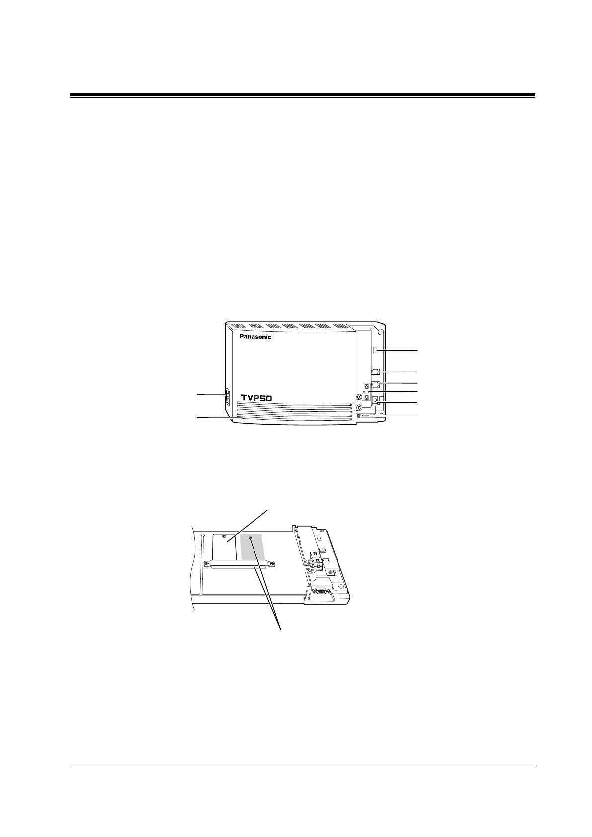
1.3.2 System Components
Main Cabinet
1.3 SYSTEM BASICS
MODE (DIP Switch)
AC Inlet
Power Indicator
POWER
Inside View of the Main Cabinet
Position for Optional Expansion Memory Card
VOICE PROCESSING SYSTEM KX-TVP50
Memory Card
Port 1
Port 2
Ferrite Core
Earth Terminal
EIA (RS-232C)
Connector
VOICE PROCESSING SYSTEM OVERVIEW
15
Page 16
1.3 SYSTEM BASICS
System Components
AC Inlet:
Connects the power cable to an AC outlet dedicated for the VPS.
Power Indicat or:
Indicates system status — when flashing, the system is off-line (not ready to receive calls).
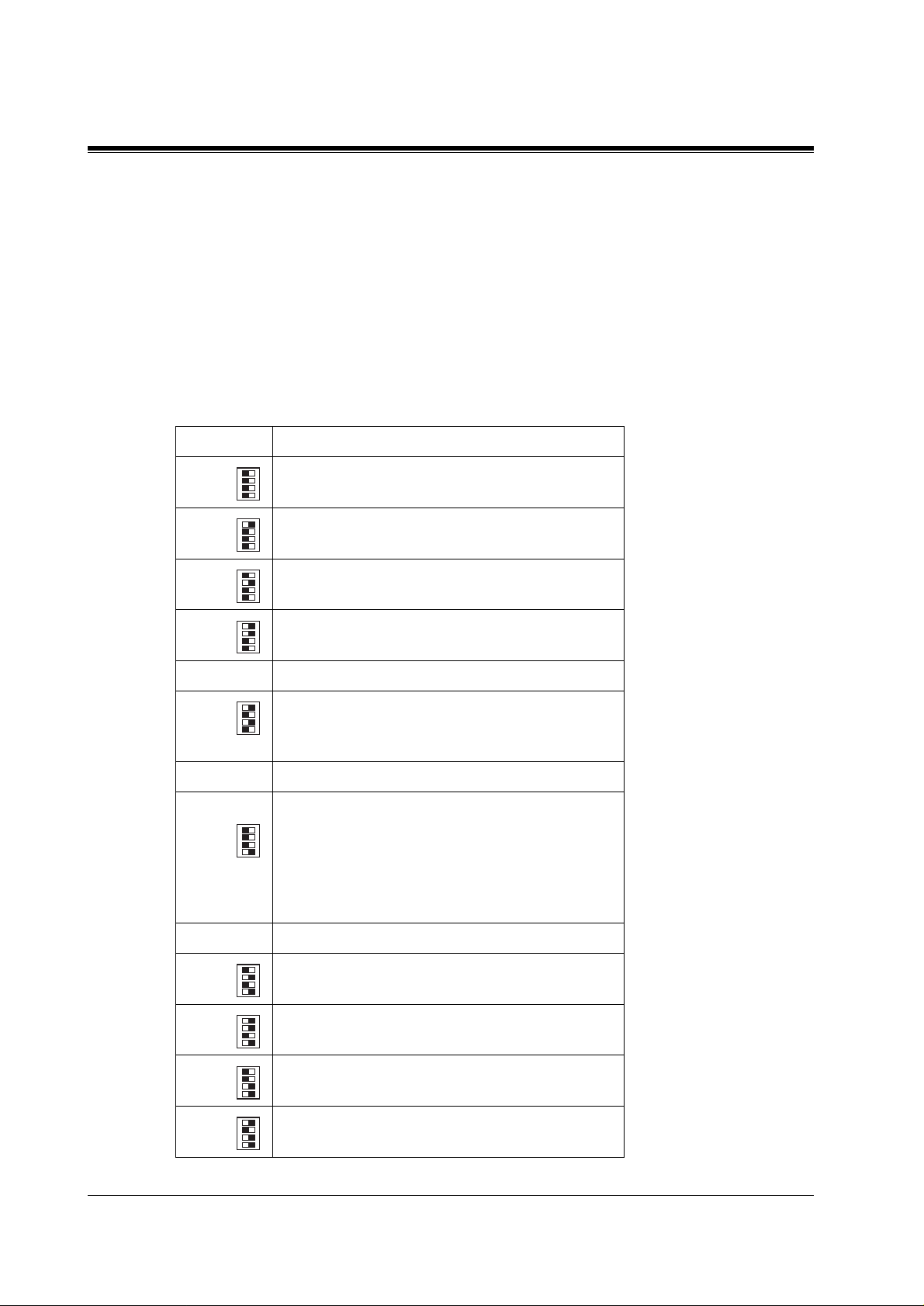
MODE (DIP Switch):
(Check the status of this switch only at start-up.) Provides the following additional functions:
0 Normal setting. (All switches in 0 position.)
1
2
Table 1
Position Additional Function
01
•1
01
•2
01
•3
01
•4
01
•1
Initialises RS-232C parameters.
01
•2
01
•3
01
RS-232C default parameters: 9,600, N, 8, 1
•4
01
•1
Auto Configuration is automatically executed and
01
*1
•2
01
•3
01
all ports are set for Automated Attendant service.
•4
01
•1
Auto Configuration is automatically executed and
01
3
*1
•2
01
•3
01
all ports are set for Voice Mail service.
•4
4 Reserved.
01
•1
Initialises the VPS. Clears all voice data (except
01
•2
01
•3
5
01
User 1 and User 2 prompts) and retur ns all syste m
•4
parameters to the default sett ing.
6-7 Reserved.
Initialises the VPS. Clears all voice data and
01
returns all syste m parameters to the de fault setting.
•1
01
•2
01
•3
This makes more recor ding time av ailable — about
01
8
•4
1 h — if User Prompts have been recorded.
CAUTION:
erased!
9 Reserved.
01
•1
Auto Configuration is automatically executed and
01
10
11
12
*2
*2
•2
01
•3
01
•4
all ports are set for Automated Attendant service.
01
•1
Auto Configuration is automatically executed and
01
•2
01
•3
01
all ports are set for Voice Mail service.
•4
01
•1
All service prompts are set to System Prompts
01
•2
01
•3
01
•4
(Factory-recorded English prompts).
User 1 and User 2 Prompts are
16
13
01
•1
All service prompts are set to User 1 Prompts
01
•2
01
•3
01
•4
(Factory-recorded Spanish prompts).
VOICE PROCESSING SYSTEM OVERVIEW
Page 17

1.3 SYSTEM BASICS
Table 1
Position Additional Function
01
•1
All service prompts are set to User 2 Pr ompts (n ot
01
14
01
01
•2
•3
•4
recorded).
15 Reserved.
*1
For Panasonic KX-TD series telephone systems with DPT
Integration
*2
For Panasonic KX-TA series telephone system with APT
Integration.
To change the position, use a pointed object, such as a pen, etc.
Note
When setting the DIP switc h to any position (except 0), first disconnect the station wire(s)
and wait a few minutes, then disconnect the AC cord from the VPS. Set the DIP switch
and connect the AC cord to the VPS; wait appro ximately 3.5 min and then return t he DIP
switch to position 0.
Earth Termin al:
This terminal should be connected to a earth source with less than 1 resistance.
EIA (RS-232C) Connector:
Connects an ASCII or VT terminal to the VPS; must be used to program system.
Memory Card:
(1/system) Stores the proprietary system program, a nd the voi ce prompts (abou t 30 min wort h);
has the capacity to record approximately 2 h of messages from callers.
Optional Expansion Memory Card:
The KX-TVP52 can expand the flash memory capacity of the KX-TVP50 by 2 h.
1.3.3 Which Phone Systems are Compatible?
We recommend integration with the following Panasonic phone systems:
•
Panasonic KX-TD1232
•
Panasonic KX-TD816
•
Panasonic KX-TA series
W e cann ot guarantee adequate int egration of the KX-TVP50 wit h other PBX systems or with
Key Systems. If the customer does not have one of the recommended Panasonic PBX
systems, be sure that the system has the features listed below.
VOICE PROCESSING SYSTEM OVERVIEW
17
Page 18

1.3 SYSTEM BASICS
The PBX should have the following features for successful integration:
If the PBX does not have these features, VPS operation will be limited.
See 3.1.4 PBX Requirements for Integration. You will find the foll owi ng informati on about
each feature listed:
VOICE MAIL
The recommended Panasoni c PBX systems ha v e Fo llo w- on ID and Inb and Inte gra tion. When
callers are t ransferred to an extension that is forwarded to Voice Mail, Follow-on ID sends
callers dire ctly to the mailbox. Without Follow-on ID, the ca ller would have to re-ente r the
mailbox number when connected to the Voice Mail.
•
Single line (tip/ring) port circuits (Some PBXs need an OPX card to provide this
connection.)
•
Station to station DTMF signalling
•
Message Waiting Notification from an SLT (single-line telephone)
•
Screened transfer from an SLT
•
Message Waiting Notification on proprietary (multi-line) sets (message waiting lamp
accessed by dialling on/off codes)
•
Description
•
Limitations of the system without the feature
•
Tests to determine whether the PBX has the feature
DTMF Integration enables the VPS to recognise the current state of the call and improve its
call handling performance . When enabled, the PBX informs the VPS of the status of the call
(busy , answered, ringing, etc.) by sending a code with DTMF tones before sending the normal
call progress tones. For example, when a caller hangs up before making a selection, the PBX
sends # 9 to the VPS port that answered. This informs the VPS that the caller has hung up.
Upon receiving these digits, the VPS goes on-hook and is ready to handle another call.
Digital (APT/DPT) Inte gratio n is a va ilable when the VPS is connected t o a Pa nasonic KX-TA
series PBX or to a Panasonic KX-TD series PBX (depending on the software version). This
digital integration provides the V PS with more information than D TMF Integration . This
information enables the sys tem to ident ify the e xt ensio n n umber of the call er, know wher e the
call is forwarded from and why, and recognise what the caller wants to do. Some fe atures are
available only with APT/DPT Integration (Live Call Screening, Two-Way Recording, TwoWay Transfer, Direct Mailbox Access, Intercom Paging, Auto Configuration, Caller Name
Announcement (system/personal), Caller ID Call Routing, Personal Greeting for Caller ID).
1.3.4 Installer Equipment and Software Requirements
The installer
software. We suggest you use something li ke Hype rTerminal by HILGRAEVE. The computer
is used to program the VPS. T erminal emulation software enables the keyboard to be used as a
data entry device.
have a l apt op comput er or dat a t er m ina l e qui pped with terminal emulation
must
18
VOICE PROCESSING SYSTEM OVERVIEW
Page 19

While both the laptop and data terminal will work, the laptop allows screens to be saved in a
file thr oughout the pr ocess. It is of ten he lpful to retr ie ve these files late r if te chnica l suppo rt is
needed.
1.3.5 Specifications
Number of Messages per Mailbox: 100 maximum (programmable)
1.3 SYSTEM BASICS
Table 2
Ports: 2
Voice Storage: 2h (expandible)
Custom Services: 100
Message Retention: 1 to 30 days or unlimited
Number of Mailboxes: 30 subscriber mailboxes
2 manager mailboxes
1.3.6 Hard war e
•
1 Flash Memory Card
•
1 Optional Flash Memory Position for KX-TVP52 card
•
2 Telephone Inputs (RJ11C)
•
1 RS-232C Connector
•
1 DIP Switch (4-bit)s
1.3.7 Flash Memory Expansion Capabilities
Expansion of the flash memory capacity requires an optional expansion memory card (KXTVP52). The KX-TVP50 initially has 2-h memory. The KX-TVP52 increases the capacity by
2 h.
1.3.8 Recommendations for System Configuration
General guideline: a ratio of 6/1 (for every 6 lines, 1 port). There are 2 questions to ask when
considering how many ports are desirable:
• Are the ports answering all incoming calls or just forwarded/transferred calls?
• If they are answering incoming calls, how busy are the lines?
The guideline above (6/1) usually works well with moderate traffic. This may have to be
modified for heavy traffic. These recommendations are outlined in the following chart.
VOICE PROCESSING SYSTEM OVERVIEW
19
Page 20

1.3 SYSTEM BASICS
One port may not support an Automated Attendant configuration with 5 outside (CO) lines.
The following recommendations for Automated Attendant ports may have to be modified for
heavy traffic.
Table 3
Outside (CO) lines Port
1-6 1
7-12 2
Table 4
Outside (CO) lines Port
1-4 1
5-8 2
20
VOICE PROCESSING SYSTEM OVERVIEW
Page 21
1.4 DIGITAL INTEGRATION
1.4.1 General
There are 2 types of Digital Integration: APT Integration and DPT Integration.
APT Integration is available when the KX-TVP50 is connected to a KX-TA analogue PBX.
DPT Integration is available when the KX-TVP50 is conne cted to a KX-TD digital PBX.
1.4.2 APT Integration
To the Panasonic KX-TA analogue PBX, the VPS ports look like proprietary telephones. The
PBX thinks that the VPS is a proprietary telephone, and the VPS mimics all actions of a
proprietary telephone. Communication between the VPS and the PBX through digital
integration re quires the proper soft ware le v el in th e PBX and 4-wire conne ctions fo r each port
(TVP50). To communicate between the VPS and the PBX through APT Integration, the PBX
and VPS must be programmed to work together.
1.4 DIGITAL INTEGRATION
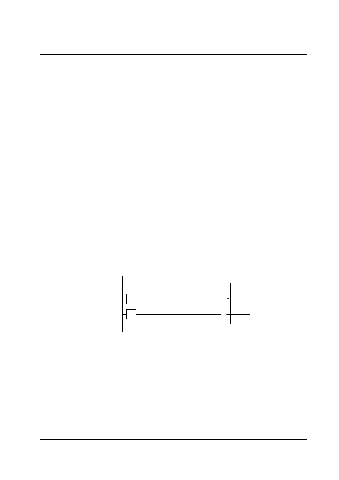
1.4.3 Connection Example — APT Integration
For example, you can connect jack 7 of the KX-TA series PBX to Port 1 of the VPS with a 4wire connection (see diagr am belo w). This connecti on creates 1 Voice Mail extension and can
only answer 1 call . This means that a fu lly-con f igur ed 2-por t sys tem req uires 2 jac ks fro m the
PBX.
KX-TVP50
KX-TA series
When APT Integr ation i s acti vated, a single e xtens ion jack pro vides 1 singl e-line i nterf ace at a
Port on the VPS. For example, when 1 line cord (4 wire) is c onne cte d to Port 1 on the VPS, 1
extension is provided.
7
8
1.4.4 DPT Integration
Port 1
Extension 107
Port 2
Extension 108
To the Panasonic KX-TD digital PBX, the VPS ports look like digital extensions. The PBX
thinks that the VPS i s a di gita l phone , and t he VPS mimic s all acti ons of a dig ital se t. Another
advantage of digital i ntegratio n is that the 2B+D communication provides 2 VPS ports for each
Digital Station port . Communication between t he VPS and the PBX throu gh digital inte gration
requires the proper software level in the PBX and 4-wire connections for each port (TVP50).
VOICE PROCESSING SYSTEM OVERVIEW
21
Page 22
1.4 DIGITAL INTEGRATION
To communicate between the VPS and the PBX through DPT Integration, the PBX and VPS
must be programmed to work together.
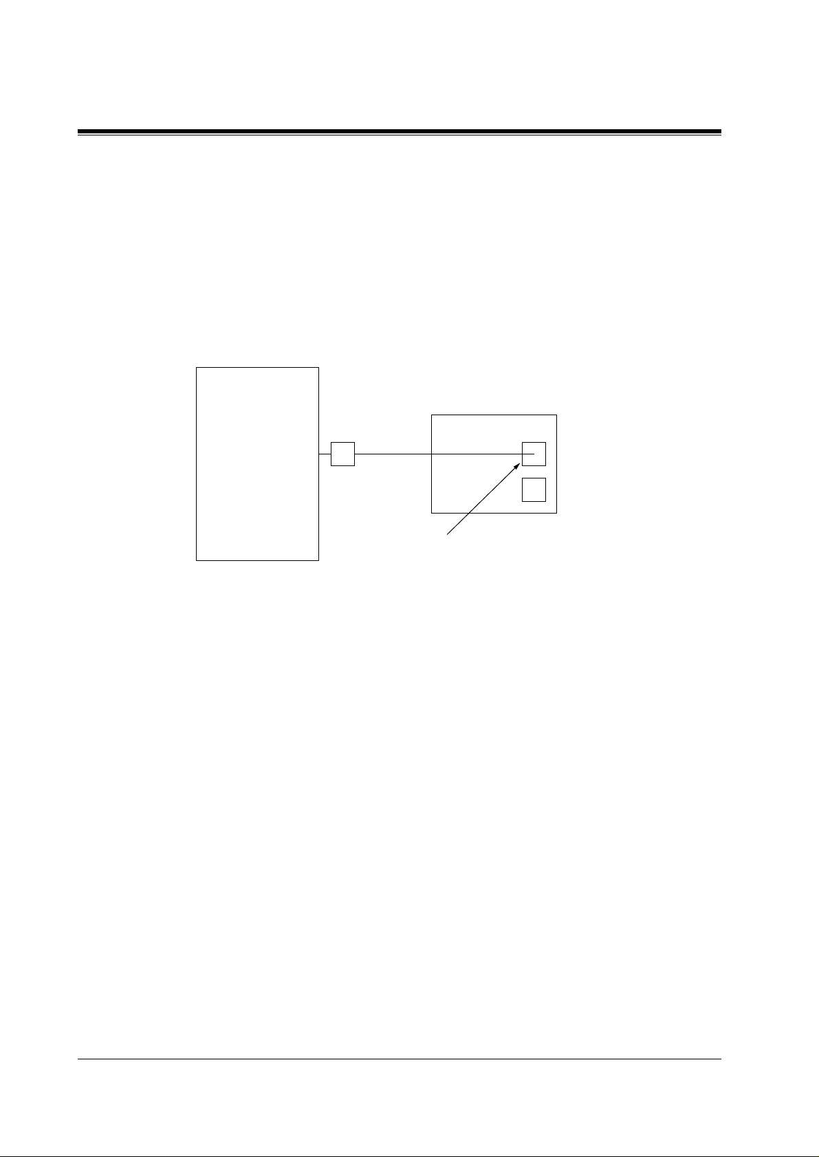
1.4.5 Connection Example — DPT Integration
For example, you can connect jack 15 of the KX-TD1232 to Port 1 of the VPS with a 4-wire
connection (see diagram below). This connection creates 2 Voice Mail extensions and can
simultaneously answer 2 calls. This means that a ful ly-conf igured 2- port system re quires only
1 jack from the PBX.
KX-TVP50
KX-TD1232
15
Port 1
Extensions 165 and 166
When DPT Integrati on is activated, a si ngle e xt ension jack pro vi des 2 si ngle-li ne int erf aces a t
a Port on the VPS. F or e xample, when 1 l ine co rd (4 wires) is c onnecte d to Po rt 1 o n the VPS,
2 extensions are provided.
22
VOICE PROCESSING SYSTEM OVERVIEW
Page 23

Section 2
INSTALLATION
INSTALLATION
23
Page 24

2.1 SAFETY PRECAUTIONS
2.1 SAFETY PRECAUTIONS
Please read the following precautions before installing the VPS.
2.1.1 Installation
The VPS needs to be installed on the wall. Improper placement of the system may result in
malfunction, noise, or discolouration. Avoid installing the VPS in the following places:
•
in direct sunlight; in hot, cold, or humid places
•
in new ar eas wher e ther e ar e th ermal springs, et c. (wher e sulphuric gas may damage the
equipment or contacts).
•
where shocks or vibrations are frequent or strong.
•
in dusty places or places where water or oil may come in contact with the unit.
•
near high frequency generating devices such as sewing machines, elevators or electric
welders.
•
on or near computers, telexes, or other office equipment; near microwave ovens or air
conditioners. (Ide ally , the VPS should not be in the r oom wit h these items and should be
at least
1.8m {6 feet}
away from televisions.)
Do not obstruct the areas ar ound the PBX and the VPS.
and space on the sides for maintenance and inspection.
2.1.2 Wiring
•
Do not wire the teleph one cable parallel to an A C power sour ce, computer, etc. If cables are
run near those wires, shield the cables with metal tubing or use shielded cables and earth
the shields.
•
Use protectors if running cables on the floor. Avoid running wire under carpets.
•
A void s haring
the VPS. Induction noise from such equipment may interrupt the VPS operation.
When making any connections or remo ving the co ver, be sure the power switch is turned of f.
When installing telephone wiring, basic safety precautions should always be followed to
reduce the risk of fire, electric shock and inju ry to persons, including the following:
• Never install telephone wiring during a lightning storm.
• Never instal l telephone jacks in wet locations unless the jack is specif ically designed f or
wet locations.
• Never touch uninsul ated tele phone wires or te rminals unle ss the tel ephone line h as been
disconnected at the network interface.
• Use caution when installing or modifying telephone lines.
Both require space abo ve for coo ling
an AC
power supply for comp uter s, te le xes , and oth er o f f ice equip ment wit h
24
INSTALLATION
Page 25

2.2 UNPACKING
Unpack the box and check the items below.
Table 5
Main Unit 1
AC Cord 1
Screws (Wall Mounting) 3
Washers (Wall Mounting) 3
2.2 UNPACKING
INSTALLATION
25
Page 26
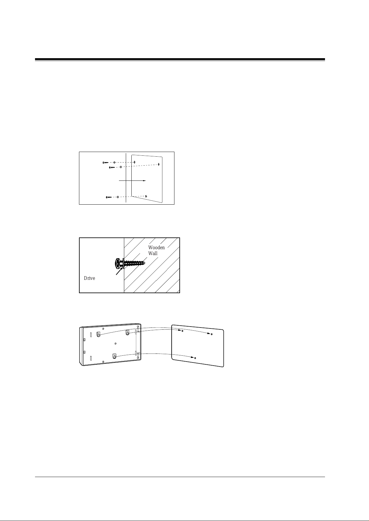
2.3 MOUNTING THE VPS ON A WOODEN WALL
2.3 MOUNTING THE VPS ON A WOODEN WALL
The wall where the VPS is to be mounted must be able to support the weight of the VPS. If
screws other than the ones supplied are used, use the same-sized diameter screws as the
enclosed ones.
1.
Place the temp late (included) on the wall to ma rk the 3 screw positions.
Template
2.
Install the 3 screws (included accessories) into the wall.
Wooden
Wall
Drive the screw
to this position.
3.
Hook the unit on the screw heads.
,
26
INSTALLATION
Page 27
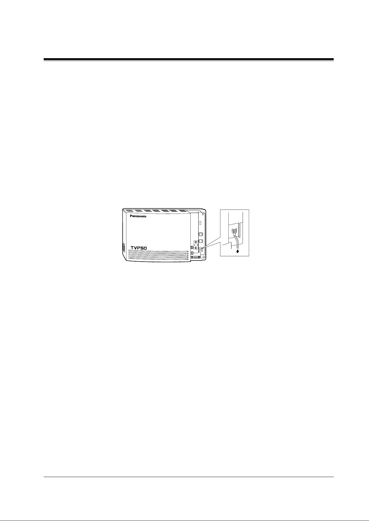
2.4 FRAME EARTH CONNECTION
IMPORTANT!!!
Connect the frame of the main unit to the earth.
1.
Loosen the screw.
2.
Insert the earth wire.
3.
Tighten the screw.
4.
Connect the earth wire to the earth.
2.4 FRAME EARTH CONNECTION
POWER
VOICE PROCESSING SYSTEM KX-TVP50
To earth
INSTALLATION
27
Page 28

2.5 INSTALLATION STEPS
2.5 INSTALLATION STEPS
The followi ng is an ov er view of the standard install atio n proces s usin g APT/DPT Integration.
When necessary, other sections in this manual have been referenced for more detailed
descriptions or instructions.
1.
Get a list of current users, their extension numbers, their departments, and the type of
systems they use (mailbox, no mailbox, beeper, car phone...).
2.
Assess your customer s' needs befor e setting up the system. You will save yourself time later
by giving cu st omers what they need up front. Ask the office manager how th e VPS will be
used. Give examples.
Recommend that your customer use a word processor to log the greetings. You will find
these files much more easily than the worksheet pages if you need to make changes down
the road.
3.
Standard initialisation (For APT/DPT Integration Connection)
a)
Program the ports of the PBX for voice processings (See Section 4 INTEGRATING
THE VPS WITH THE PANASONIC KX-TA ANALOGUE PBX AND KX-TD
DIGITAL PBX).
Program the KX-TA series, the KX-TD1232 or the KX-TD816 for Voice Mail
integration.
• KX-TA series
• KX-TD816, KX-TD1232
Program may be performed on-site or at the office.
All memory is stored and will be retained when the unit is powered up as long as
the DIP switch has been reset to position [0] prior to turning the unit off.
b)
Unplug the power cord of the VPS.
c)
Plug station wire(s) from the PBX into VPS (See 2.7 CONNECTIONS).
d)
Connect the computer to the VPS wit h a Null Modem Cable (See 2.8.2 Connecting the
RS-232C Cable).
e)
Set the DIP switch to position 5.
f)
Plug the power cord of the VPS.
g)
Wait until the "warning" appears on the screen.
h)
Set the DIP switch back to position 0.
CAUTION
If the DIP switch is not reset to position 0 after initialisation, all programming will be lost
when the voice processor loses power!
28
INSTALLATION
Page 29

2.5 INSTALLATION STEPS
4.
Perform Quick Setup. (See Section 5 CUSTOMISING THE SYSTEM)
5.
Check Quick Setup:
• The Power Indicator on the Voice Processor should be solid.
• The screen output should be: [On Line].
If you do not see the "On Line" message, check the following:
• The line cord to the Voice Processor has 4 conductors.
• The programming on the KX-TA series is correctly set in system Program [130], or
[130] and [131].
• The programming on the KX-TD81 6/12 32 is corr ectl y set i n Syste m Program [ 117].
6.
Set up Class of Service (COS) for each user. customise voice prompts if necessary. (See
Appendix B SYSTEM ADMINISTRATOR'S GUIDE)
7.
Perform Administrative Program through a computer. (See Appendix B SYSTEM
ADMINISTRATOR'S GUIDE)
CAUTION
Do not turn the power off while the VPS is activated so as not to cause malfunction.
To turn the power off after installing the VPS, unplug the power cord from the VPS a
few minutes after disconnecting station wire(s).
INSTALLATION
29
Page 30
2.6 INSTALLING AN OPTIONAL EXPANSION MEMO RY CARD (KX -TV P52)
2.6 INSTALLING AN OPTIONAL EXPANSION
MEMORY CARD (KX-TVP52)
2.6.1 General
The flash memory capacity of the KX-TVP50 can be increased from 2 h to 4 h if an optional
expansion memory card (KX-TVP52) is installed.
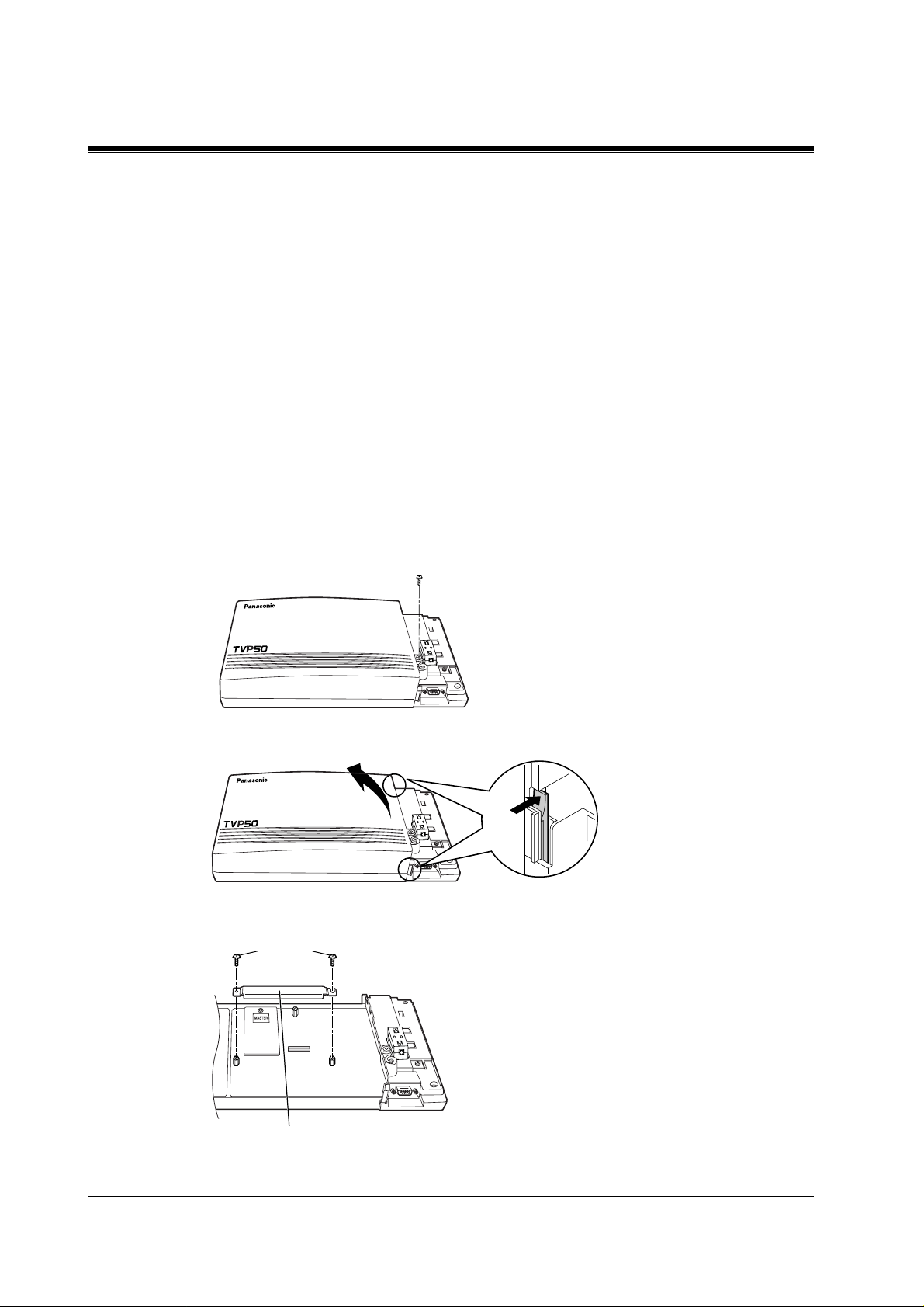
2.6.2 Installing the KX-TVP52
1.
Disconnect the station wire(s). Wait a few minutes then disconnect the AC cord from the
VPS.
2.
Take out the screw.
Screw
VOICE PROCESSING SYSTEM KX-TVP50
POWER
3.
Remove the cover by pressing both tabs and lifting up.
VOICE PROCESSING SYSTEM KX-TVP50
POWER
4.
Take out the screws and remove the metal bar.
Screws
30
Metal Bar
INSTALLATION
Page 31

2.6 INSTALLING AN OPTIONAL EXPANSION MEMORY CARD (KX-TVP52)
5.
Attach the optional expansion memory card firmly. Secure the screw.
Screw
SLAVE
CAUTION
Do not attach t he opt ional e xpansi on memory card at the "MASTER" position. Attach it at the
"SLAVE" position.
6.
Replace the metal bar and secure the screws.
Screws
7.
Replace the cover and secure the screw.
8.
Connect the AC cord again.
INSTALLATION
31
Page 32

2.7 CONNECTIONS
2.7 CONNECTIONS
2.7.1 Connecting to the PBX
The KX-TVP50 can be connected to up to 2 extension ports of the PBX. Use a 4-conductor
wire for connection with KX-TA systems that uses APT Integration, and for connection with
KX-TD systems that use DPT Integration. Use a 2-conductor wire for connection to all other
PBXs.
4-Conductor Wire
Y
G
R
B
Modular Connection
B: BLACK
R: RED
G: GREEN
Y: YELLOW
2.7.2 Opening the Ferrite Core
Insert your finger into the opening of the ferrite core and open it as shown below.
Outer Pins
Inner Pins
Y
G
R
B
32
Connect a 4-conductor wire or 2-conductor wire to the KX-TVP50 and run the wire through
the ferrite core (see following pages). Close the ferrite core.
INSTALLATION
Page 33

2.7.3 Connection for APT Integration
Ports 1-2 of the KX-TVP50
Telephone Line
Modular Jacks
PORT 1
2.7 CONNECTIONS
PORT 1
PORT 2
PORT 2
Extension Jacks 07 and 08
To Extension
Port of the PBX
Y
G
R
B
(or 15 and 16)
2.7.4 Connection for DPT Integration
Ports 1-2 of the KX-TVP50
Telephone Line
Modular Jacks
To KX-TA series
Y
G
R
B
INSTALLATION
PORT 1
PORT 2
To Extension
Port of the PBX
PORT 1
PORT 2
To KX-TD1232/816
Any Extension Jack except Jack 01
Y
G
R
B
Y
G
R
B
33
Page 34

2.7 CONNECTIONS
2.7.5 Connection for Non-APT/DPT Integration
Ports 1-2 of the KX-TVP50
Telephone Line
Modular Jacks
PORT 1
PORT 1
PORT 2
To Extension
Port of the PBX
PORT 2
To Extension Ports of
Non-APT/DPT Integration PBX
G
R
G
R
34
INSTALLATION
Page 35

2.8 TERMINAL CONNECTION
2.8 TERMINAL CONNECTION
2.8.1 Requirements for Connecting Programming Terminal
The programming terminal must be conne cted wit h a seri al cable wit h an RS-232C conne ctor
at the EIA port. This must be a null modem cable. This enables system administration (system
setup, mailbox setup, and system diagnosis) to be performed.
Communication parameters of the VPS have been set to the following values at the factory:
Table 6
COMMUNICATION PARAMETERS
Baud Rate: 9600 bps
Word Bit Length: 8 Bits
Parity: None
Stop Bit Length: 1 Bit
2.8.2 Connecting the RS-232C Cable
STOP:
Before connecting the cable, make sure the power switches on both the data terminal and
the VPS are OFF.
VOICE PROCESSING SYSTEM KX-TVP50
POWER
Insert the RS-232C cable into the VPS with the connector indicating the same direction.
INSTALLATION
The cable must be shielded and no longer than 2m {6.5 feet}.
35
Page 36

2.8 TERMINAL CONNECTION
KX-TVP50 (9 pin)
Circuit
(EIA)
type
BB
BA
CD
AB
CC
Signal
name
RXD
TXD
DTR
SG
DSR
Pin
no.
KX-TVP50 (9 pin)
Circuit
(EIA)
type
Signal
name
Pin
no.
9-pin Cable Printer/IBM-PC
name
RXD
TXD
DTR
SG
DSR
RTS
CTS
Circuit
type
(EIA)
BB
BA
CD
AB
CC
CA
CB
Signal
Pin
no.
2
3
4
5
6
2
3
4
5
6
7
8
25-pin Cable Printer/PC
name
Circuit
type
(EIA)
Pin
no.
Signal
BB
BA
CD
AB
CC
Pin
Number
1
2
3
4
RXD
TXD
DTR
SG
DSR
2
3
4
5
6
1
3FGRXDAABB
2
TXD BA
20
DTR
7
SG
5
CTS
6
DSR
8
DCD
CD
AB
CB
CC
CF
Table 7 Pin Configuration of the EIA (RS-232C)
Signal Name
FG
TXD
RXD
RTS
Frame Ground
Transmitted Data
Received Data
Request To Send
Circuit Type
EIA CCITT
AA
BA
BB
CA
101
103
104
105
36
6 DSR Data Set Ready CC 107
INSTALLATION
Page 37

Table 7 Pin Configuration of the EIA (RS-232C)
2.8 TERMINAL CONNECTION
Pin
Number
7
8
20 DTR Data Terminal Ready CD 108.2
SG
DCD
Signal Name
Signal Ground
Data Carrier Detect
2.8.3 EIA (RS-232C) Signals
Frame Ground (FG)
Connects an external ground to the unit frame, usually the earth pin of the AC power cord.
Transmitted Data (TXD)—output
Conv eys s ignals fro m the unit to the termina l/printer. A "mark" condition is held unless data or
BREAK signals are being transmitted.
Received Data (RXD)—input
Conveys signals from the terminal/printer to the unit.
Circuit Type
EIA CCITT
AB
CF
102
109
Request To Send (RTS)—output
This lead is held on whenever DSR is on.
Signal Ground (SG)
Connects to the DC ground of the unit for all interface signals.
Data Terminal Ready (DTR)—output
This signal line is turned on by the unit to indicate that it is on line. Circuit DTR ON does not
indicate that communication has been established with the terminal/printer. It is switched off
when the unit is off-line.
INSTALLATION
37
Page 38

2.8 TERMINAL CONNECTION
38
INSTALLATION
Page 39

Section 3
INTEGRATING THE VPS WITH
PANASONIC KX-T PHONE SYSTEMS
INTEGRATING THE VPS WITH PANASONIC KX-T PHONE SYSTEMS
39
Page 40

3.1 GUIDELINES FOR INTEGRATION
3.1 GUIDELINES FOR INTEGRATION
3.1.1 APT/DPT or Inband Signalling?
There are 3 types of inte gration av ailable on the KX-TVP50 : Inband Signalling, APT and DPT.
The VPS used with any other brand of telephone equipment require inband equipment.
KX-TA series PBX that can use APT Integration is:
• KX-TA series Version Y581B or higher
KX-TD series PBXs that can use DPT Integration are:
• KX-TD816 Version P301P or higher
• KX-TD1232 Version P231U or higher
3.1.2 Why Integration is Important
The KX-TVP50 works well with most PBXs because its connections are made through a
standard single-line (tip/ring) telephone interface. However, the VPS operation depends on the
capabilities and fea tures provid ed by the PBX; its perfo rmance will v ary when connected with
different PBX systems. For example, Follow-on (or Called Party) ID is a feature of the PBX.
If the PBX does not have this feature, the VPS cannot transfer calls directly to the correct
mailbox and play the busy or no-answer greeting for that mailbox.
3.1.3 How the VPS and the PBX Communicate
T o the PBX, the VPS looks like SLT sets. The PBX thinks that the VPS is an SLT, a nd the VPS
mimics all actions a live attendant would carry out from an SLT.
For the VPS and the PBX to communicate, proper signalling is important. Like an attendant,
the VPS places calls by going off-hook and dialling numbers. It starts call transfers with a
hookswitch flash to put callers on hold and then dials the extension number. By recognising
call progress tones from the PBX, the VPS decides how calls should be handled. Inband
Integration al lo ws the PBX to send ce rtain digit s (DTMF) to the VPS, allo wing it to recogni se
the status of the extension and take the appropriate action.
Table 8
VPS/PBX COMMUNICATION
PBX to VPS
Call Progress Tones SLT Signals
• ringback
•busy
•reorder
VPS to PBX
• on/off hook
• hookswitch flash
• DTMF tones
40
DTMF Tones
INTEGRATING THE VPS WITH PANASONIC KX-T PHONE SYSTEMS
Page 41

The VPS must also have access to certain PBX features. For example, if the VPS takes a
message, one way it can notify the mailbox owner is by dialling the PBX's Message-WaitingLamp-On code. Once new messages are retrieved, the VPS dials the Message-Waiting-LampOff code for that same mailbox owner.
3.1.4 PBX Requirements for Integration
The PBX must have certain capabilities and features to work with the VPS. (Although this
section includes tests to help you evaluate the PBX, it may be necessary to refer to the PBX's
documentation for detailed capability and feature descriptions.)
Single Line (Tip/Ring) Port Circuits
The VPS can only be connected to a PBX that supports SLT sets. Some PBXs need an OPX
card to provid e this connection .
listed in this section.
Howeve r, some OPX cards do not provide all the capabil ities
3.1 GUIDELINES FOR INTE GRATION
Following are the minimum current and voltages that the PBX must supply:
Table 9
Minimum Loop Current 20 mA
Minimum Line Voltage 7 V DC
Minimum Ringing Voltage 40 V AC
Station to Station DTMF Signalling
For system users to access VPS services and features, they must be able to send DTMF tones
from their telephones to the VPS port. As a general rule, SLT sets can perform station-tostation DTMF signalling; however, many proprietary telephones cannot. Some PBXs need to
be programmed to make proprietary sets use DTMF signalling.
If the PBX does not provide station-to-stat i on DTM F si gna ll ing, VPS services and features
will be limited.
TEST:Call an SLT extension from the telephone in question. When the call
is answered, see if the person receiving the call hears DTMF tones when
numbers are dialled.
Message Waiting Notification from an SLT
The PBX extensi ons should light a lamp or rec eiv e stutter dial tone when the Message-WaitingLamp-On code is dialled by the VPS. The VPS functions best when the extension number of
the voice mailbox o wner follo ws the Light-On or Light-Of f code. On some PBXs, howe ver , the
INTEGRATING THE VPS WITH PANASONIC KX-T PHONE SYSTEMS
41
Page 42

3.1 GUIDELINES FOR INTEGRATION
extension number is dialled first, followed by a hookswitch flash and then the On code. This
presents a problem if the extension is answered before the VPS sends the hook-switch flash.
If the PBX do es not provide message waiti ng notificat ion from an SLT, the VPS can only
notify mailbox owners by dialling a beeper number or user-assigned extension.
This process slo ws down VPS performance as it dials the beeper or extension number and w aits
to confirm notif ic ation. The bee per or user -ass igned e xtension notif icati on is meant to be us ed
for necessity, usually for mailbox owners who are of t en out of t he office (e.g., sale s peo ple or
field representatives). The only other option, without message waiting notification, is for
mailbox owners to periodically call the VPS to check for messages.
TEST: See if dialling the On code from an SLT can turn on an extension's
message waiting indicator.
Screened Transfer from an SLT
The PBX must provide a screened transfer from an SLT for the VPS to function properly.
A screened transfer:
1.
Puts the caller on hold, usually with a hookswitch flash.
2.
Dials the extension.
3.
Checks to see if th e call ed subs criber is in , out, or o n anothe r lin e, and whether or n ot that
subscriber accepts the transfer.
4.
Completes the transfer (b y going on-hook) or returns to the caller to say that the party is
busy or not available. It then gives the caller an opportunity to leave a message.
If the PBX does not provide screened transfer from an SLT, the VPS cannot give callers the
option to leave a message in a subscriber's mailbox.
TEST: Place an outside call from an SLT. See if you can set up a screened
transfer to another extension. Next, try the same test with an internal call.
(The VPS may have to transfer both types of calls.)
Follow-on ID or Called Party ID
When forwarding or transf erring a call to the VPS, a PBX with Foll ow-on ID sends the mailbox
number of the called subscrib er to th e VPS befo re connec ting the caller. The VPS responds by
playing that subs criber's p ersonal gr eeting. This operation is sometimes ca lled Call Forw ard to
Mailbox. W i thout this feature, the VPS canno t i m medi ate ly play the greeting when the l ine is
busy or there is no answer and allow the caller to leave a message.
42
INTEGRATING THE VPS WITH PANASONIC KX-T PHONE SYSTEMS
Page 43

3.2 PBX PARAMETERS AND PORT SETTINGS
3.2 PBX PARAMETERS AND PORT SETTINGS
3.2.1 General Guidelines and Definitions
Optimal performance of the VPS/PBX system relies on proper VPS programming. There are
3 categories of hardware settings: RS-232C, Port Settings, and PBX Interface Parameters.
Entering a number sets some of the parameters, while others use sequence codes.
3.2.2 RS-232C Settings
Baud Rate (300 - 38400):
•
transferred).
Word Bit Length (7 - 8):
•
Parity (N, O, E):
•
Stop Bit Length (1 - 2):
•
Default:
•
9600, 8, N, 1
Specifies the parity used for error detection.
Specifies the bits-per-second (the speed at which the data is
Defines the number of bits in each byte or character.
Specifies the number of bits used to signify the end of the byte.
3.2.3 Port Settings
There is no need to change these in a typical installation.
using an outside (CO) line directl y to the KX-TVP50. Each port on the VPS should be matched
to the type of signalling the PBX expects. I f you need to c hange these set tings, refer to the PBX
manual or customer support office to get the correct values for these settings.
Flash Time—100, 300, 600, 900
•
The minimum amount of time that the PBX requires to recognise a hookswitch flash.
Choose the amount that is equal to or greater than the PBX's setting.
CPC Signal (Calling Party Control Signal)—NONE, 6.5, 150, 300, 450, 600
•
The amount of time allowed for the short break in loop current that is used to indicate
that the caller has hung up; usually set to NONE, since most PBXs do not provide this
signal to single line port s. If c hoosi ng a set ting othe r than NONE, use an amount e qual
to or less than the PBX or telephone company provided CPC signal.
Disconnect Time—1 - 8
•
The amount of time that the line is temporarily unavailable after a call has ended.
Dial Mode—DTMF, Pulse 10
•
The type of signalling the PBX single line port expects to receive. (
second)
s:
ms:
, Pulse 20
pps
Only change the se parame ters when
ms:
:
pps
pps
= pulses per
INTEGRATING THE VPS WITH PANASONIC KX-T PHONE SYSTEMS
43
Page 44

3.2 PBX PARAMETERS AND PORT SETTINGS
3.2.4 PBX Interface Parameters
Dialing Parameters
PBX Type:
•
Specifies the type of PBX which is connected to the VPS.
Integration Mode:
•
Specifies the met hod of inte gr ation to be used be tween the VPS and PBX. If PBX type is se t
to the Panasonic KX-T series, the Inband Signalling parameters are set automatically and
should not be altered. APT Integration is only available when a KX-TA series PBX is
connected and the software is upgraded. DPT Integration is only available when a KX-TD
series PBX is connected and the software is upgraded.
Table 10
SEQUENCE CODES
D Disconnect
F Hookswitch Flash
R Ring Detection
S Silence Detection
T Dialtone Dete ction
W Wait for 1 Second
X Dial Extension
A: Answer
0-9, , #
Operator Transfer Sequence:
•
Tells the VPS how to transfer a call to the operator.
Example:
Extension Transfer Sequence:
•
Tells the VPS how to transfer a call to an extension.
Example:
Alternate Extension (Transfer Sequence):
•
Tells the VPS how to transfer a call to an extension that is entered into the "Alternate
Extension Group." This is use ful for extensions that nee d a s pecial tr ans fer procedure (i.e.,
blind transfer) such as modem extensions.
Example:
Reconnect Sequence on Busy:
•
T ell s the VPS how to r eturn to th e caller if the e xtension the c aller has dialle d is busy. PBXs
differ in how they handle this function. Test from an SLT to determine the sequence.
Reconnect Sequence on No Answer:
•
Tells the VPS how to return to the caller if the extension the caller has dialled does not
FTX [hookswitch flash—dial tone—dial (operator) extn.]
FTX [hookswitch flash—dial tone—dial extn.]
FTXD [hookswitch flash—dial tone—dial extn.—hang up]
DTMF Digits
44
INTEGRATING THE VPS WITH PANASONIC KX-T PHONE SYSTEMS
Page 45

3.2 PBX PARAMETERS AND PORT SETTINGS
answer. PBXs differ in how they handle this function. Test from an SLT to determine the
sequence.
Reconnect Sequence on Refused Call:
•
T ells the VPS how to return to the caller if the extension dialled has Call Screening enabled
and the subscriber ch ooses not to take the call. PBXs differ in how t hey handle thi s function.
Test from an SLT to determine the sequence.
Light On Sequence for Message Waiting Lamp:
•
This is the dialling sequence that the VPS must use to turn on a message waiting lamp at
an extension.
Light Off Sequence for Message Waiting Lamp:
•
This is the dialling sequence that the VPS must use to turn off a message waiting lamp at
an extension.
Call Waiting S equence:
•
This sequence is carried out by the VPS to perform call waiting when the extension being
called is busy. PBXs differ in how the y ha ndl e t his function. Test from an SLT to determine
the sequence.
Release Sequence for Call Waiting:
•
This sequence is carried out by the VPS to release call waiting. PBXs differ in how they
handle this function. Test from an SLT to determine the sequence.
Inband Signalling
These parameters are used when the Integration Mode is set to Inband. If the PBX type is set
to a KX-T series system, these parameters will be automatically set. If another type PBX is
used, check that system's installation manual for settings.
Code
(default)
1 Ringback Tone The extension dialled is ringing.
2 Busy Tone The extension dialled is busy.
3
4 DND The extension dialled has set DND feature (Do Not
5 Answer The extension dialled is answered.
6
Table 11
Call State Sent to the Voice Mail Port When...
Reorder Tone An invalid extension number is dialled or the call is
inadvertently connected to another Voice Mail port (also
heard when no DTMF recei ver is av ailable to the Voice Mail
extension).
Disturb).
Forwarded to V oice
Mail (Ringing)
The extension dialled is fo rwarded to Voice Mail an d
another Voice Mail port is able to answer. (This lets the f irst
Voice Mail port, usually an Auto Attendan t, send the cal l to
the other Voice Mail port.)
INTEGRATING THE VPS WITH PANASONIC KX-T PHONE SYSTEMS
45
Page 46

3.2 PBX PARAMETERS AND PORT SETTINGS
Table 11
Code
Call State Sent to the Voice Mail Port When...
(default)
Forwarded t o V oice
7
8
9
Mail (Busy)
Forwarded to Extn. The extension dialled is forwarded to another, non-Voice
Confirmation Tone The Message Waiting Lamp On or Message Waiting Lamp
Disconnect The caller disconnects. The central office must set a CPC
#9
Digit Translation Table Parameters
These parameters all ow PBXs that have a fix ed Follo w-on ID seq uence to be used wi th the KXTVP50. For example, a Follow-on ID sequence of [ 101] can be changed to [#6101] by
using these parameters.
Inter-Digit T i me-Ou t:
•
on ID) from the PBX to the VPS. The Digit Translation Table applies the digits received
within this ti me to translation.
Input-Output (up to 8 alphanumeric characters):
•
within the inter-digit time, it checks them ag ainst the input table. If they are found, the
system utilises the output digits in their place.
This parameter de fines the interval of i ncoming signals (Follow-
The extension dialled is forwarded to Voice Mail and no
other Voice Mail ports ar e a va ilable t o accep t the call . (This
signals the Voice Mail port [usually Auto-Attendant] to let
the caller to leave a message.)
Mail extension.
Off code is dialled successfully.
signal to the PBX line for this signal to work for outside
calls.
When the system receives digits
46
The Remainder of this section consists of step-by-step guides for software verification
and programming of the recommended Panasonic PBX systems.
INTEGRATING THE VPS WITH PANASONIC KX-T PHONE SYSTEMS
Page 47

3.3 CONNECTING THE VPS WITH PAN A SONIC KX-T SERIES PBXs
3.3 CONNECTING THE VPS WITH PANASONIC
KX-T SERIES PBXs
3.3.1 KX-TVP50 Programming for Inband Integration
Set parameters from the System Administration Terminal. The table below lists recommended
parameters for Panasonic KX-T series PBXs.
Table 12
PBX Type Other
Manufacturers
Integration Mode None None None None None None None None
Inband Inband Inband Inband Inband Inband Inband
Operator T ransfer
Sequence
Extension
Transfer
Sequence
Alternate
Extension
Transfer
Sequence
Reconnect
Sequence on
Busy
Reconnect
Sequence on No
Answer
FX (A) FTX
FX (A) FTX
FX (A) FTX
FWW FWW FWW FWW FWW FWW FWW FWW
FWW FWW FWW FWW FWW FWW FWW FWW
T308/
T616
(A)
(A)
(A)
T1232 T96 T336 TD816/
1232
FTX (A) FTX
(A)
FTX (A) FTX
(A)
FTX (A) FTX
(A)
FTX
(A)
FTX
(A)
FTX
(A)
FTX (A) FTX
FTX (A) FTX
FTX (A) FTX
TD308 T A series
FTX (A)
(A)
FTX (A)
(A)
FTX (A)
(A)
Reconnect
Sequence on
Refuse Call
Light-On
Sequence for
Message Waiting
Lamp
Light-Off
Sequence for
Message Waiting
Lamp
Call Waiting
Sequence
INTEGRATING THE VPS WITH PANASONIC KX-T PHONE SYSTEMS
FWW FWW FWW FWW FWW FWW FWW FWW
* N/A T701X# T#91X
* N/A T702X# T#90X T#9X T700X T700X T702X#
* N/A1N/AN/A111
T9X
T701X T701X T701X#
47
Page 48

3.3 CONNECTING THE VPS WITH PANASONIC KX-T SERIES PBXs
Table 12
PBX Type Other
Manufacturers
Release Sequence
for Call Waiting
* Check with manufacturer.
N/A Not Available
(A) Adding " A" for "answer" to the operator and extension transfer elimina tes the message:
"You have a call" when the AA transfers a call. The VPS disconnects after line is
answered. Adding "D" for "disconnect" creates a blind transfer.
* N/AFN/AN/AFFF
T308/
T616
T1232 T96 T336 TD816/
1232
TD308 T A series
3.3.2 KX-TA series Programming for Inband Integration via the
Manager's Extension
1.
Enable System Program [102] for each extension connected to the VPS. Jack 07, or jacks
07 and 08 can be assigne d for the VPS1 as the Voice Mail port. Jack 15, or jacks 15 and 1 6
can be assigned for the VPS2.
This parameter is used to tell the KX-T A series which extensions are connected to the VPS.
Ports with this parameter enabled can receive Follow-on ID and DTMF call status
Signalling (busy, answered, disconnect, etc.) if the Voice Mail integration and DTMF
Integration features are also enabled.
48
2.
Enable System Prog ra m [103] to turn on DTMF Integration. On exten sions with the Voice
Mail port parameter enabled, the KX-TA series can send codes (DTMF tones) to indicate
call states; this increases VPS efficiency. Codes apply to all transferred calls: outside calls
only indicate disc onnect (provi ded the KX-TA series is programmed for CPC Detection and
the Central Office sends the CPC signal). Refer to the Table 11 in Section 3.2.4 PBX
Interface Parameters.
3.
Put all extensions connected to the VPS into 1 extension group using System Program
[600].
Reserve this extension group for these extensions! Do not mix other extensions into this
group.
NOTE
Up to two KX-TVP50 units can be connected to the KX-TA series. When two KX-TVP50
units are connected to the KX-TA series, 2 different extensi on groups should be assigned
for each KX-TVP50 in System Program [600]. One extension group is for jack 07, or
jacks 07 and 08 o f the KX-TA series. The other extension group is f or jack 15, or jack s 15
and 16.
INTEGRATING THE VPS WITH PANASONIC KX-T PHONE SYSTEMS
Page 49

3.3 CONNECTING THE VPS WITH PAN A SONIC KX-T SERIES PBXs
4.
Enable hunting for the VPS extension groups using System Program [100].
5.
Set the hunting type for the VPS e xtens ion groups to circ ula r using Syste m Progra m [101].
6.
At every VPS e xtension, temporar ily connect an SLT or butt set, go of f-hook and dial 7301#
to turn on Data Line Security. This prevents the KX-TA series from sending Executive
Override or Call W aiting tones to these extensions. We recommend that all V oice Mail port
extensions have this feature enabled to avoid interruption of recording.
7.
Select the appropriate outside (CO) line feature settings depending on how your customer
plans to use the VPS: A) to answer all incoming calls, B) as an operator backup, or C) to
only answer calls not an swered by user extensions.
Recommended outside (CO) line feature settings:
a)
If the KX-TVP50 is answering all incoming calls:
Outside (CO) Li ne Mo de
Mode), [416](Lunch Mode) to set this parameter. Program all lines DIL to the first
extension of the Voice Mail hunt group. The KX-TA series will allow incoming
outside calls t o hunt only if the outs ide (CO) l ines are DIL t o the f irst p ort of the h unt
group. Lines programmed as Normal do not hunt.
b)
If the KX-TVP50 is only answering calls not answered by the operator (Operator
Backup):
Flexible Ringing Assignment
Programs [408](Day Mode), [409](Night Mode) and [410](Lunch Mode) to enable
ringing at the operator's extension(jack).
Delayed Ringing Assignmen t
the VPS picks up, we recommend setting the delay to a few seconds for each
extension connected to the KX-TVP50. Use System Programs [411](Day Mode),
[412](Night Mode) and [413](Lunch Mode).
Outside (CO) Line Mode
Normal. Use System Programs [414 ](Day Mode), [415](Night Mode) and
[416](Lunch Mode) to set this parameter.
c)
If the KX-TVP50 is only answering calls not answered by user extensions:
Flexible Ringing Assignment
Programs [408](Day Mode), [409](Night Mode) and [410](Lunch Mode) to enable
ringing on every extension (jack) that you want to have ring.
Delayed Ringing Assignment
VPS picks up, we recommend setting the delay to a few seconds for each extension
connected to the KX-T VP 50. Us e Sys te m Programs [411](Day Mode), [412](Ni ght
Mode) and [413](Lunch Mode).
Outside (CO) Line Mode
Normal. Use System Programs [414](Day Mode), [415](Night Mode) and
[416](Lunch Mode) to set this parameter.
— Use System Programs [414] (Day Mode ), [41 5]( Night
— For each appli cable outsi de (CO) line, u se System
— T o giv e the op erator time to answer th e call bef ore
— Set the mode for each applicable outside (CO) line to
— For each appli cable outside (CO) line, use S ystem
— To give users time to answer the call before the
— Set the mode for each applicable outside (CO) line to
INTEGRATING THE VPS WITH PANASONIC KX-T PHONE SYSTEMS
49
Page 50

3.3 CONNECTING THE VPS WITH PANASONIC KX-T SERIES PBXs
CAUTION
DO NOT create a mailbox in both VPS for the same extension. Each extension can have a
maximum of 1 mailbox in either VPS. The extension should assign a Voice Mail extension
from the VPS which contains its mailbox as the destination for Call Forwarding and Voice
Mail Trans f e r. DO NOT assign a Voice Mail extension from the other VPS. For e xampl e, i f
jack 06 (extension 106) has its mailbox in the VPS1, assign extension 107 or 108 as the
destination, not extension 115 or 116 (see the following diagram).
Extension 106
KX-TA series
6
7
8
Group A
15
16
Group B
KX-TVP50 (VPS1)
KX-TVP50 (VPS2)
Port 1
Extension 107
Port 2
Extension 108
Mailbox for Extension 106
Port 1
Extension 115
Port 2
Extension 116
3.3.3 KX-TD816 and KX-TD1232 Programming for Inband
Integration via the Manager's Extension
Select a maximum of 2 station ports to be con nected to the VPS. Plug eac h station into a Voice
Mail port.
Go into System Program [602] and assign the Voice Mail stations to a different extension
group. By default, all stations are in Extension Group 1.
Go into System Program [106] and assign the new Extension Group to Auto Attendant (AA).
3.3.4 KX-TD816 and KX-TD1232 Programming for Inband
Integration via the Operating and Maintenance Tool
1.
Go to the Main Menu. Choose System Data Programming.
(BATCH [1] or INTERACTIVE [2]).
•
Before choosing Batch Programming, you must open a file in the Disk File
Management Menu (Item 3).
•
Before choosing Interactive Programming, you must connect with the system in the
DSHS Connect/Disconnect menu.
50
INTEGRATING THE VPS WITH PANASONIC KX-T PHONE SYSTEMS
Page 51

Main Menu
1. System Data Programming (BATCH)
2. System Data Programming (INTERACTIVE)
3. Disk File Management
4. DSHS Management
5. DSHS Connect/Disconnect
6. Quit
Select the number : [ ]
2.
Choose
Station
from the
System Data Programming Main Menu
System Data Programming Main Menu
1. Line
2. Station
3. System
4. Toll Restriction
5. ARS
6. Aux. Ports
7. Additional Function
8. Caller ID
Select the number : [ 2 ]
3.3 CONNECTING THE VPS WITH PAN A SONIC KX-T SERIES PBXs
.
3.
Choose
Station Setting 1
from the
Station Menu
1. Station Setting 1
2. Station Setting 2
3. COS & Mailbox ID
4. CO line Outgoing
5. DIL 1:N
6. ISDN Extension Setting
7. ISDN Extension CO outgoing
8. Flexible CO Keys
9. Flexible PF Keys
10. DSS
11. Lunch/Break Group
12. FWD/DND Setting
Station Menu
13. PS Setting 1
14. PS Setting 2
15. PS COS & Mailbox ID
16. PS CO line Outgoing
17. PS DIL 1:N
18. PS Password
19. PS Flexible Keys
20. PS System
21. PS Registration
22. PS Termination
23. CS Information
24. PS Data Clear
Select the number: [1]
.
INTEGRATING THE VPS WITH PANASONIC KX-T PHONE SYSTEMS
51
Page 52

3.3 CONNECTING THE VPS WITH PANASONIC KX-T SERIES PBXs
4.
Enable XDP ports. Place Voice Mail extensions in Extension Group 8.
Station Setting 1
Jack EXT Name X E Doorphone DDI No. CLIP LCS
D X Day Night Trams /COLP Mode
P G 1 2 3 4 1 2 3 4
01-1 [ 101 ] [ ] N
01-2 [ 201 ] [ ] -
02-1 [ 102 ] [ ] N
02-2 [ 202 ] [ ] 03-1 [ 103 ] [ ] N
03-2 [ 203 ] [ ] 04-1 [ 104 ] [ ] N
04-2 [ 204 ] [ ] 05-1 [ 105 ] [ ] Y
05-2 [ 205 ] [ ] 06-1 [ 106 ] [ ] Y
06-2 [ 206 ] [ ] -
07-1 [ 107 ] [ ] N
07-2 [ 207 ] [ ] 08-1 [ 108 ] [ ] N
08-2 [ 208 ] [ ] -
[ 1 ] Y Y Y Y Y Y Y Y [ ] DDI Stop Rec
[ 1 ] N N N N N N N N [ ] DDI
[ 1 ] N N N N N N N N [ ] DDI Stop Rec
[ 1 ] N N N N N N N N [ ] DDI
[ 1 ] N N N N N N N N [ ] DDI Stop Rec
[ 1 ] N N N N N N N N [ ] DDI
[ 1 ] N N N N N N N N [ ] DDI Stop Rec
[ 1 ] N N N N N N N N [ ] DDI
[ 1 ] N N N N N N N N [ ] DDI Stop Rec
[ 8 ] N N N N N N N N [ ] DDI
[ 1 ] N N N N N N N N [ ] DDI Stop Rec
[ 8 ] N N N N N N N N [ ] DDI
[ 1 ] N N N N N N N N [ ] DDI Stop Rec
[ 1 ] N N N N N N N N [ ] DDI
[ 1 ] N N N N N N N N [ ] DDI Stop Rec
[ 1 ] N N N N N N N N [ ] DDI
5.
Return to the
6.
Choose
System Menu
System Data Programming Main Menu
Miscellaneous
01. Day/Night
02. Class of Service
03. Emergency/Quick Dial
04. Speed Dial
05. Absent Message
06. Flexible Numbering
07. Account Code
08. Special Carrier
09. Timer
10. Voice Mail
11. Voice Mail Integration
12. UCD
13. Phantom
14. Opera/Manager/EXT Group
from the
System Menu
Select the number: [15]
. Select
System.
.
15. Miscellaneous
16. Caller ID Modification
17. MFC Code
18. ISDN DATA
19. FLT. EXT. DDI No.
20. DID
21. Lunch/Break Time
22. System Time
23. Version
24. ISDN Card
25. CS-INF Card
26. E1 Card
27. E1 Minor Error
52
INTEGRATING THE VPS WITH PANASONIC KX-T PHONE SYSTEMS
Page 53

3.3 CONNECTING THE VPS WITH PAN A SONIC KX-T SERIES PBXs
7.
Choose the Call Hunting extension gro up. Set the last e xtension group to
Attendant.
Miscellaneous
for Automated
[A]
Expansion Card Type (Master) =>
(Slave ) =>
Local Access => Priority =
Call Hunting => EXG
SPD TRS Override => HOTEL FEATURE =>
CO Auto-Hold by Push DSS-Key
Adjust Time
PBX Code
8.
Return to the
Setting 1
TRG No. =
No.
=
CO-Key => Off-Hook Monitor
System Data Programming Main Menu
. Program all lines DIL to the first extension of the Voice Mail hunt group.
EXP1
1
[1] [2] [3] [4] [5] [6] [7] [8]
12345678
D
Disable Off
=> Enable
Disable
=> [01:00] AM
=> [ ]
=> CONTINUOUSE&M Signal
=> UseDID Transfer Table
=> [ ]PS N/A EXT.
S6
S2
EXP2
EXT2
EXT2
2
D
EXP3
EXT1
EXT1
3
D
4
D
DID SELECT
5
D
Caller ID Extension
EXP 1 Not Stored
EXP 2 Not Stored
EXP 3 Not Stored
EXP 4 Not Stored
6
D
=>
=>
. Select
7
D
EXT Number
Enable
Line
8
A
and then select
Outside (CO) Line Setting
CO C T D PD C CPC DIL 1:1 DIL 1:1
No O R I PT I Detection EXT No
NG A SM D Out NightMode Day
LF
01 Y [1] D 1080 N DisableDisable
02 Y [2] D 1080 N DisableDisable
03 Y [3] D 1080 N DisableDisable
04 Y [4] D 1080 N DisableDisable
05 Y [5] D 1080 N DisableDisable
06 Y [6] D 1080 N DisableDisable
07 Y [7] D 1080 N DisableDisable
08 Y [8] D 1080 N DisableDisable
09 Y [8] D 1080 N DisableDisable
10 Y [8] D 1080 N DisableDisable
11 Y [8] D 1080 N DisableDisable
12 Y [8] D 1080 N DisableDisable
EXT[205]EXT[205]
EXT[205]EXT[205]
EXT[205]EXT[205]
EXT[205]EXT[205]
EXT[205]EXT[205]
EXT[205]EXT[205]
EXT[205]EXT[205]
EXT[205]EXT[205]
EXT[205]EXT[205]
EXT[205]EXT[205]
EXT[205]EXT[205]
EXT[205]EXT[205]
R
E
V
Reg.
Reg.
Reg.
Reg.
Reg.
Reg.
Reg.
Reg.
Reg.
Reg.
Reg.
Reg.
Lunch
Group
[ ]
[ ]
[ ]
[ ]
[ ]
[ ]
[ ]
[ ]
[ ]
[ ]
[ ]
[ ]
Break
Group
[ ]
[ ]
[ ]
[ ]
[ ]
[ ]
[ ]
[ ]
[ ]
[ ]
[ ]
[ ]
CO Line
INTEGRATING THE VPS WITH PANASONIC KX-T PHONE SYSTEMS
53
Page 54

3.3 CONNECTING THE VPS WITH PANASONIC KX-T SERIES PBXs
54
INTEGRATING THE VPS WITH PANASONIC KX-T PHONE SYSTEMS
Page 55

Section 4
INTEGRATING THE VPS WITH THE
PANASONIC KX-TA ANALOGUE PBX AND
KX-TD DIGITAL PBX
INTEGRATING THE VPS WITH THE PANASONIC KX-TA ANALOGUE PBX AND KX-TD DIGITAL PBX
55
Page 56

4.1 GUIDELINES FOR DIGITAL INTEGRATION
4.1 GUIDELINES FOR DIGITAL INTEGRATION
4.1.1 Why Digital Integration is Important
The KX-TVP50 works well with most PBXs because its connections are made through a
standard single line (tip/ring) telephone interface. However, the communication between the
PBX and VPS is best when Digital Integration is used; the KX-TVP50 is already set up to
communicate through Digital Integration.
Once Digital Integr ation is established, th e PBX sends information to the VPS through the data
link. This information ena bl es the VPS to identify the extension th at i s cal li ng, know where a
call is forwarded and why it's forwarded, and recognises what the caller wants to do. This
communication allows features that are only available with Digital Integration, several of
which are described below.
Table 13
DIGITAL INT EGRATION FEATURES
Auto Configuration The VPS knows what extension numbers exist on the
PBX and creates mailboxes for each extension
automaticall y . Also sets the VPS clock with data fr om
the PBX clock.
Live Call Screening Extension users can monitor messages as they are
being left in the mailbox and intercept if required.
T w o-Way Recording Extension users can rec ord con v ersations in their o wn
mailboxes by pressing one button.
Two-Way Transfer Extension users can record conversations in another
person's mailboxes by pressing a button and dialling
an extension number.
Direct Mailbox Access The subscriber is entered directly into his mailbox
when he calls the VPS. He does not have to dial his
mailbox number.
Trunk Service
(Universal Port)
Intercom Paging* Callers can page subscribers through built-in speakers
Each PBX outside line (trunk) group can be assi gne d
one of 4 incoming call services: Voice Mail Service,
Automated Attendant Service, Interview Servic e and
Custom Service.
and external pagin g equipment. For a Caller ID Ca ller,
if his name has been recorde d for the Caller Name
Announcement feature, the na me will be announced at
the end of the page.
56
INTEGRATING THE VPS WITH THE PANASONIC KX-TA ANALOGUE PBX AND KX-TD DIGITAL PBX
Page 57

4.1 GUIDELINES FOR DIGITAL INTEGRATION
Table 13
DIGITAL INTEGRATION FEATURES
Caller Name Announcement
(System/Personal)*
A pre-recorded announcemen t of the Caller ID callers'
name is heard when ext ension users listen to messages
left in their mailbox and/or calls are transferred from
the VPS to the users.
Caller ID Call Routing* The VPS automatically sends calls from pre-assigned
Caller ID numbers to the desired extension, mailbox
or Custom Service.
Personal Greeting for Caller ID* Each subscriber can record up to 4 personal greeting
messages for special callers.
* Caller ID note: When an incoming outside call reaches the VPS via t he PBX,
the VPS will wait ab out 2 rings before answer ing the call to rece ive t he Caller
ID information properly from the PBX.
The KX-TVP50 System comes from the fact ory already set up for a KX-TA series PBX. When
the power is turned on for the first time, the VPS will try to communicate with the KX-TA
series PBX through Digital Integration. For this reason, several things should be done before
operating for the first time.
INTEGRATING THE VPS WITH THE PANASONIC KX-TA ANALOGUE PBX AND KX-TD DIGITAL PBX
57
Page 58

4.2 CONNECTING THE KX-TVP50 WI TH THE PANASONIC KX-TA series
4.2 CONNECTING THE KX-TVP50 WITH THE
PANASONIC KX-TA series
4.2.1 KX-TA series Software Verification and Programming for
Digital Integration via the Manager's Extension
It is important that the KX-TA series has the proper software level to allow Digital Integration
with the VPS. Follow the procedures below to confirm the software level, then complete the
required programming before starting up the VPS.
All of the fol l o wing procedures must be done after entering system programming. Refer
to the KX-TA series Installation Manual for instructions on how to enter the system
programming mode.
Software Verification
1.
Check the software version of the KX-TA series using System Program [998].
Example:
The underlined digits represent the software production date code (year, month, day). For
Digital Integration, the software version of the PBX must be Y581B or higher.
Y581BYYMMDD
(M)
If the softwa re version of the PBX is lower than this, consult your dealer.
From the
a)
b)
2.
Set the date and time using System Program
Date and time are automat ically s ynchro nised b etwe en the VP S and the Pa nasoni c KX-TA
series during initial setup.
3.
Assign the
the VPS. This allows the PBX to send the pro per Digital Integration inf ormation to those
ports. Jack 07, or jack s 07 and 08 ca n be assigned fo r the VPS1 as the Voice Mail Port. Jack
15, or jacks 15 and 16 can be assigned for the VPS2.
SYS-PGM NO ?
Enter
Press
date it was created.
This version must be Y581B or higher for Digital Integration to be utilised.
KX-TVP50 (2 ports): assign max. 2 jacks
•
.
[998]
the
NEXT
Voice Mail Port.
screen:
button (SP-PHONE). The system displays the ROM version and the
.
[000]
This program tells the PBX which jacks will be connected to
58
INTEGRATING THE VPS WITH THE PANASONIC KX-TA ANALOGUE PBX AND KX-TD DIGITAL PBX
Page 59

Extension
group 7
7
4.2 CONNECTING THE KX-TVP50 WITH THE PANASONIC KX-T A serie s
KX-TVP50 (VPS1)
Port 1
Port 2
Port 1
Port 2
KX-TA series
From the
a)
Enter
[130]
b)
Press
the
8
15
16
Extension
group 8
SYS-PGM NO ?
(for VPS1) or
NEXT
button (SP-PHONE).
KX-TVP50 (VPS2)
screen:
[131]
(for VPS2).
Screen output: Disable
c)
Press
the
SELECT
button (AUTO-ANSWER).
Screen output: Port 7 or Port 15
d)
To assign 2 jacks,
Press
the
SELECT
button (AUTO-ANSWER) again.
Screen output: Port 7& 8 or Port 15& 16
To assign 1 jack, skip this step.
e)
Press STORE.
f)
Press END
(HOLD).
Conditions: The lowest jack (jack 07 or jack 15) entered here must
be connected to the Port 1 of the VPS.
To change the current assignment from "Port 7" to
"Port 7 & 8", you must first change it to "Disable".
Likewise, if you want to change it from "Port 7 & 8" to
"Port 7", you must first change it to "Disable". If the
current assignment is already "Di sable", you can mak e
a change in 1 step. This condit ion also applies to System
Program [131].
When "Port 7 & 8" is selected in program [130],
extension jack numbers 07 and 08 will be in extension
group 7 automatically. Likewise, when "Port 15 & 16"
is selected in pr ogram [131], ext ension jac k numbers 15
and 16 will be in extension group 8 automaticall y. Also
the Station Hunting type is set as "Circul ar"
automatically in each of these 2 extension groups.
4.
Select the appropriate outside (CO) line feature settings depending on how your customer
plans to use the VPS: A) to answer all incoming calls, B) as an operator backup, or C) to
only answer calls not an swered by user extensions.
Recommended outside (CO) line feature settings:
INTEGRATING THE VPS WITH THE PANASONIC KX-TA ANALOGUE PBX AND KX-TD DIGITAL PBX
59
Page 60

4.2 CONNECTING THE KX-TVP50 WI TH THE PANASONIC KX-TA series
a)
If the KX-TVP50 is answering all incoming calls:
Outside (CO) Line Mode
Mode), [416](Lunch Mode) to set this parameter. Program all lines DIL to the first
extension of the Voice Mail hunt group. The KX-TA series will allow incoming
outside calls t o hunt only if the outs ide (CO) lin es are DIL to the f irst por t of the hunt
group. Lines programmed as Normal do not hunt.
b)
If the KX-TVP50 is only answering calls not answered by the operator (Operator
Backup):
Flexible Ringing Assignment
[408](Day mode), [409](Night Mode) and [410](Lunch Mode) to enable ringing at
the operator's extension(jack).
Delayed Ringing Assign ment
the VPS picks up, we recommend sett ing the del ay to 3 or 4 rings for each e xtensi on
connected to the KX-TVP50. Use Sy stem Programs [411](Day Mode), [412](Night
Mode) and [413](Lunch Mode).
Outside (CO) Line Mode
Programs [414 ](Day Mode), [41 5](Nig ht Mo de) a nd [41 6]( Lunch Mode ) to se t th is
parameter.
—Use System Programs [414](Day Mode), [415](Night
—For each outside (CO) line, use System Programs
— T o gi ve th e operato r time to an swer the cal l before
— Set the mode for each CO to Normal. Use System
Table 14 2 Outside (CO) Lines, 2 Ports
Outside (CO)
Lines
11, 2
21, 2
c)
If the KX-TVP50 is only answering calls not answered by user extensions:
Flexible Ringing Assignment
[408](Day Mode), [409](Nig ht Mode) and [4 10](Lunc h Mode) to enab le ringi ng on
every extension (jack) that you want to have ring.
Delayed Ringing Assignment
VPS picks up, we recommend setting the delay to 3 or 4 rings for each extension
connected to the KX-TVP50. Use Sy ste m Pro gra ms [ 411] (Da y Mode) , [ 412] (Ni ght
Mode) and [413](Lunch Mode).
Outside (CO) Line M ode
System Programs [414](Day Mode), [4 15](Ni ght Mode) a nd [416] (Lunch Mode ) to
set this parameter.
5.
Unplug or power down the KX-TA series.
— Set the mode for each outside (CO) li ne to Normal. Use
Ports
— For each outsid e (CO) li ne, use System Pr ograms
— To give users time to answer the call before the
60
6.
Connect the jack(s) assigned in Step 3 to the KX-TVP50.
7.
Connect your laptop computer to the KX-TVP50 and start your communication software
(i.e., HyperTerminal, Procomm Plus, Smartcom...).
INTEGRATING THE VPS WITH THE PANASONIC KX-TA ANALOGUE PBX AND KX-TD DIGITAL PBX
Page 61

4.2 CONNECTING THE KX-TVP50 WITH THE PANASONIC KX-T A serie s
8.
Set the DIP switch on the KX-TVP50 to position 5.
Only perform this step when initially setting up the system.
CAUTION
Setting the DIP switch to position 5 will default the Voice Processing System, resulting in a
loss of all user programming, and voice messages (except User 1 and User 2 prompts).
9.
Plug in and power up the KX-TVP50 and wait approximately 3.5 min while the system
initialises.
"System Administration" Start-Up Sequence
Before starting the VPS, make sure all installation and line connections have been
done as described in Section 2.
Plug in and
the power switch to ON on the KX-TA series. The calls to the VPS can be
turn
processed after the Power Indicator stops flashing.
After turning the power on, the system starts up in the following sequence:
•
The Power Indicator light goes on.
•
The Power Indicator light begins to flash.
•
"Checking Flash Memory Cards." is displayed on the screen.
Screen output:
Checking Flash Memory Cards.
Please wait...
PORT TEST...
SYSTEM SETUP
1... 2... 3...
•
The VPS tests the CPU card, the flash memory, and the ports
until "1...2...3..." is displayed.
•
Active ports are displayed on the screen.
Screen output:
Active COs: 1 2
APT Interface Connection is Established
** ON LINE MODE **
The display will alert you if System Setup is not completed successfully.
INTEGRATING THE VPS WITH THE PANASONIC KX-TA ANALOGUE PBX AND KX-TD DIGITAL PBX
61
Page 62

4.2 CONNECTING THE KX-TVP50 WI TH THE PANASONIC KX-TA series
Screen output:
Active COs: 1 2
APT Interface Connection is not Established
** OFF LINE MODE **
This message is shown when the digital (APT) connection between the VPS and
telephone system cannot be established.
Possible causes of the message: "APT Interface Connection is not Established"
Table 15
Cause Action
The PBX is not a KX-TA series
system. Since the def ault PBX type for
Change the PBX type by using
Quick Setup (see Section 5).
the KX-TVP50 is to KX-TA series at
the factory, this message will
always
appear when connecting to another
type of PBX.
The cabling between the PBX
extension ports and the VPS is not 4wire or is improperly connected.
The PBX is a KX-TA series but does
not have the proper level of software
required to support APT Integration.
The PBX is not programmed properly
to support APT Integration.
Confirm the cabling is
connected as described in
Section 2 INSTALLATION.
Consult your dealer or use
Inband Integration under
hardware se ttings.
Do required integration
programming as described in
this chapter.
10.
Start up completed.
a)
The Power Indicator light stops blinking when the start-up has been successful. (The
delay varies according to the system's condition.)
b)
"**ON LINE MODE**"
c)
System prompt [>] is di splayed on the screen. To enter system admi nistration,
ENTER
. All parameters can be set through the menu-driven program.
is displaye d.
11.
Go to the
and
QSET
System Administration Top Menu.
Press ENTER
for Quick Setup and foll o w the Aut o Conf igurati on Instru ctions.
Type
[5]
and
Press ENTER
, or Type
Press
then
[3]
62
INTEGRATING THE VPS WITH THE PANASONIC KX-TA ANALOGUE PBX AND KX-TD DIGITAL PBX
Page 63

4.2 CONNECTING THE KX-TVP50 WITH THE PANASONIC KX-T A serie s
CAUTION
When 2 VPSs are connected to t he KX-TA series, the following 2 pro cedures should b e done
to make the VPSs work correctly.
1.
Delete a mailbox in either VPS so that each extension has only ONE MAILBOX.
After Auto Configuration has been executed, an extension has a mailbox in both
VPS1 and VPS2. However each extension can have a maximum of 1 mailbox in
either VPS. To delete a mailbox, Type [D] (Delete) in the "Make (Make/Delete)"
2.
KX-TA series
field (see "Step 4 Creating Mailboxes" in
The extension should assign a Voice Mail extension from the VPS which contains
its mailbox as the destination for Call Forwarding and Voice Mail Transfer. DO
NOT assign a Voice Mail extension from the other VPS. For example, if jack 06
(extension 106) has its mailbox in the VPS1, assign extension 107 or 108 as the
destination, not extension 115 or 116 (see diagram below).
Change the extension numbers of both VPS port 1 and 2 for VPS2 from 107 and
108 to 115 and 116 (see "Extension Number of VPS Port 1" and "Extension
Number of VPS Port 2" in Table 69 in
Extension 106
6
KX-TVP50 (VPS1)
7
8
Mailbox for Extension 106
5.1.3 Starting the Quick Setup).
B7.3 PBX Interface Parameters
Port 1
Extension 107
Port 2
Extension 108
).
KX-TVP50 (VPS2)
15
16
TEST: Press the INTERCOM button and then [107]. If the VPS
answers, you have an APT connection.
Set the DIP switch to position 0 after initialisation is complete.
The required programming is complete and the VPS and KX-TA series should be able to
communicate through Digital Integration.
When running the Quick Setup command (Section 5 CUSTOMISING THE SYSTEM) from the
VPS, the PBX transmits the station information automatically. This saves time when programming
the VPS.
Port 1
Extension 115
Port 2
Extension 116
INTEGRATING THE VPS WITH THE PANASONIC KX-TA ANALOGUE PBX AND KX-TD DIGITAL PBX
63
Page 64

4.3 CONNECTING THE KX-TVP50 WI TH THE PANASONIC KX-TD816 AND KX-TD1232
4.3 CONNECTING THE KX-TVP50 WITH THE
PANASONIC KX-TD816 AND KX-TD1232
Note
Do not use system programs [106] or [602] for DPT Integration. The following 2 Sections
(
4.3.1 KX-TD1232 Software Verification and Programming for Digital Integration via the
Manager's Ex tension
Digital Integration via the Operating and Maintenance Tool
examples. Please refer to them for the KX-TD816
4.3.1 KX-TD1232 Software Verification and Programming for
Digital Integration via the Manager's Extension
It is important that the KX-TD1232 has the proper software level to allow Digital Integration
with the VPS. Follow the procedures below to confirm the software level, then complete the
required programming before starting up the VPS.
and
4.3.2 KX-TD1232 Software Verification and Programming for
) are for the KX-TD1232 as
.
Note
Two methods of programming are available on the KX-TD1232. The instructions below
show how to program without the operating and maintenance tool. For instructions on
programming with the operating and maintenance tool, please see
Software Verification and Programming for Digital Integration via the Operating and
Maintenance Tool.
All of the fol l o wing procedures must be done after entering system programming. Refer
to the KX-TD1232 Installation Manual for instructions on how to enter the system
programming mode.
4.3.2 KX-TD1232
Software Verification
1.
Verify Software - If you are configuring a 2-cabinet system, remember to check both
cabinets. The software must be the same in each. Check the software version of the KXTD1232 using System Program [116].
Example:
The underlined digits represent the software production date code (year, month, day). For
Digital Integration, the software version of the PBX must be P231U or higher.
(For KX-TD816, th e version must be version P301P or higher for Digital In tegration to be
utilised.)
P231UYMMDD
A
64
If the softwa re version of the PBX is lower than this, consult your dealer.
From the
a)
Enter
INTEGRATING THE VPS WITH THE PANASONIC KX-TA ANALOGUE PBX AND KX-TD DIGITAL PBX
SYS-PGM NO ?
[116].
screen:
Page 65

4.3 CONNECTING THE KX-TVP50 WITH THE PANASONIC KX-TD816 AND KX-TD1232
b)
c)
2.
Set the date and time using System Program
Date and time are automatic ally synchr onised betw een the VPS and th e Panas onic KX-TD
series telephone systems during initial setup.
3.
Assign the
the VPS. This allows the PBX to send the proper Digital Integration information to those
ports.
a)
b)
c)
d)
e)
the
Press
Enter the system number (
version and the date it was created.
This version must be P231U or higher for Digital Integration to be utilised (both
systems if system connection is used).
•
Note
If you are configuring a 2-cabinet system, all Voice Mail Ports should be assigned to
either the Master or Slave System.
From the
Enter
Press
Screen output: M: # # # #
Enter the jack number of the port you will use for the Voice Mail (02 - 64).
Press STORE.
Press END
NEXT
Voice Mail Port
KX-TVP50 (2 ports): assign 1 jack
SYS-PGM NO ?
[117].
the
NEXT
button (SP-PHONE).
or
[0]
[1]
. This program tells the PBX which jack will be connected to
screen:
button (SP-PHONE).
(HOLD) when finished.
, master/slave). T he system di splays the ROM
.
[000]
Conditions: Jack 01 cannot be used as a Voice Mail port. A jack
programmed as a Manager Extensio n (System Program
[006]) cannot be used in this program.
4.
Skip this step unless setting flexible numbering.
System Program [118] (Voice Mail Extension Number Assignment) is aut omatically set.
This program allo ws you to as sign an extension number to each Voice Mail port. Since
the jack connected to th e VPS provides 2 ext ensions, this enables yo u to assign extension
numbers to each port. You can assign any extension number th at is not alre ady assigne d
to another port. To reach the VPS, users dial thes e extensio n numbers. It is not necessary
to change the default programming for the extensions 165 and 166.
From the
a)
Enter
b)
Press
Screen output: VM NO?
INTEGRATING THE VPS WITH THE PANASONIC KX-TA ANALOGUE PBX AND KX-TD DIGITAL PBX
SYS-PGM NO ?
[118].
the
NEXT
screen:
button (SP-PHONE).
65
Page 66

4.3 CONNECTING THE KX-TVP50 WI TH THE PANASONIC KX-TD816 AND KX-TD1232
c)
d)
e)
f)
Conditions: No 2 jacks on the system can have the same extension
5.
Unplug or power down the KX-TD1232.
6.
Connect the jack assigned in Step 3 to the KX-TVP50.
7.
Connect your laptop computer to the KX-TVP50 and start your communication software
(i.e., HyperTerminal, Procomm Plus, Smartcom...).
Communication Parameters: 9600, 8 Bit, None, 1
the
Press
Screen output: VM-01:#_ _ -1: 165
( _ _ = the port number you entered in program 117)
Enter the extension number that you want this port to have.
(The default extension number for port 1: 165; port 2: 166)
Press STORE.
Repeat c, d, and e until all extension numbers are entered.
NEXT
button (SP-PHONE).
number. If you try to enter a number that is already
assigned, you will hear an error tone. Each digital
extension connected provides 2 Voice Mail ports and
must have 2 different extension numbers assigned.
8.
Set the DIP switch on the KX-TVP50 to position 5.
Only perform this step when initially setting up the system.
CAUTION
Set the DIP switch to posi tion 5 wi ll defa ult th e Voice Processing System, resulting in a loss
of all user programming, and voice messages (except User 1 and User 2 prompts).
9.
Plug in and power up the KX-TVP50 and wait approximately 3.5 min while the system
initialises.
"System Administration" Start-Up Sequence
Before starting the VPS, make sure all installation and line connections have been
done as described in Section 2.
Plug in and
processed after the Power Indicator stops flashing.
After turning the power on, the system starts up in the following sequence:
•
The Power Indicator li ght goes on.
•
The Power Indicator light begins to flash.
•
"Checking Flash Memory Cards." is displayed on the screen.
the power switch to ON on the KX-TD1232. The calls to the VPS can be
turn
66
INTEGRATING THE VPS WITH THE PANASONIC KX-TA ANALOGUE PBX AND KX-TD DIGITAL PBX
Page 67

4.3 CONNECTING THE KX-TVP50 WITH THE PANASONIC KX-TD816 AND KX-TD1232
Screen output:
Checking Flash Memory Cards.
Please wait...
PORT TEST...
SYSTEM SETUP
1... 2... 3...
•
The VPS tests the CPU card, the flash memory, and the ports
until "1...2...3..." is displayed.
•
Active ports are displayed on the screen.
Screen output:
Active COs: 1 2
APT Interface Connection is not Established
** OFF LINE MODE **
This message is shown when the digital (DPT) connection between the VPS and
telephone system cannot be established. This is normal. This message appears because
the PBX type for the VPS is not a KX-TD seri es system. Since the default PBX type is
set to the KX-TA series at the factory, this message will always appear. To change the
default, go to the
System Administration Top Menu
, and Type1-6-3-1. (Program Hardware Settings - PBX Interface Parameters - Dialing Parameters Menu). Select
"2:KXT Series" at the "1. PBX Type", and select "4:DPT" at the "2. Integration Mode".
Exit the menu by entering "\ ", and the following d isplay will be shown.
Screen output:
** OFF LINE MODE **
If "DPT Interface Connection is not Established" is still shown, possible causes
are:
Table 16
Cause Action
The cabling between the PBX
extension ports and the VPS is not 4wire or is improperly connected.
The PBX is a KX-TD series but does
not have the proper level of software
required to support DPT Integration.
The PBX is not pro grammed p roperly
to support DPT Integration.
Confirm the cabling is
connected as described in
Section 2 INSTALLATION.
Consult your dealer or use
Inband Integration under
hardware settings.
Do required integration
programming as described in
this chapter.
INTEGRATING THE VPS WITH THE PANASONIC KX-TA ANALOGUE PBX AND KX-TD DIGITAL PBX
67
Page 68

4.3 CONNECTING THE KX-TVP50 WI TH THE PANASONIC KX-TD816 AND KX-TD1232
10.
Start up completed.
a)
The Power Indicator light stops blinking when the start-up has been successful. (The
delay varies according to the system's condition.)
b)
"
**ON LINE MODE**
c)
System prompt [>] is di splayed on the screen. To enter system admi nistration,
ENTER
11.
Go to the
QSET
TEST: Press the INTERCOM button and then [165]. If the VPS
answers, you have a DPT connection.
Set the DIP sw itch to position 0 a fter initialisation is complete.
The required programming is complete and the VPS and KX-TD1232 should be able to
communicate through Digital Integration.
. All parameters can be set through the menu-driven program.
System Administration Top Menu.
and
Press ENTER
" is displayed.
Type
[5]
for Quick Setup and foll o w the Aut o Conf igurati on Instru ctions.
and
Press ENTER
, or Type
Press
then
[3]
When running the Quick Setup command (Section 5 CUSTOMISING THE SYSTEM) from
the VPS, the PBX transmits the station information automa tically. This saves time when
programming the VPS.
4.3.2 KX-TD1232 Software Verification and Programming for
Digital Integration via the Operating and Maintenance Tool
Follow these steps after communication between the KX-TD1232 and the programming
software has been established. Refer to the Operating and Maintenance manual for
connection information.
1.
Check the software version.
a)
Go to the Main Menu.
b)
Verify the Operating and Maintenance version being used.
Sample display: DB data (PC): Empty
This version must be 3.60X or higher to program the KX-TD1232 for Digital
Integration.
the
Press
Version:3.60X
ALT
key and the let ter
at the same time.
[V]
68
Note
If you have an older version of the maintenance tool but have the correct ROM
INTEGRATING THE VPS WITH THE PANASONIC KX-TA ANALOGUE PBX AND KX-TD DIGITAL PBX
Page 69

4.3 CONNECTING THE KX-TVP50 WITH THE PANASONIC KX-TD816 AND KX-TD1232
version in the system, you may still program the KX- TD1232 but you must
program using the Manager's Extension.
c)
Verify the ROM version of the KX-TD1232.
Example:
P231UYMMDD
B
This version must be at least version P231U or higher for Digital Integration to be
utilised (both systems if system connection is being used).
(For KX-TD816, the version must be at least version P301P or higher for Digital
Integration to be utilised.)
If the software version of the PBX is lower than this, consult your dealer.
In the example abo v e, the underl ined digit s represent the softw are product ion date co de
(year, month, day).
2.
Go to the
Main Menu.
Choose
System Data Pr ogramming .
(BATCH [1] or INTERA CTIVE
[2]).
Main Menu
1. System Data Programming (BATCH)
2. System Data Programming (INTERACTIVE)
3. Disk File Management
4. DSHS Management
5. DSHS Connect/Disconnect
6. Quit
Select the number : [ ]
INTEGRATING THE VPS WITH THE PANASONIC KX-TA ANALOGUE PBX AND KX-TD DIGITAL PBX
69
Page 70

4.3 CONNECTING THE KX-TVP50 WI TH THE PANASONIC KX-TD816 AND KX-TD1232
3.
Choose
System
from the
System Data Programming Main Menu.
System Data Programming Main Menu
1. Line
2. Station
3. System
4. Toll Restriction
5. ARS
6. Aux. Ports
7. Additional Function
8. Caller ID
Select the number : [ 3 ]
4.
Choose
Voice Mail Integration
from the
System Menu.
System Menu
01. Day/Night
02. Class of Service
03. Emergency/Quick Dial
04. Speed Dial
05. Absent Message
06. Flexible Numbering
07. Account Code
08. Special Carrier
09. Timer
10. Voie Mail
11. Voice Mail Integration
12. UCD
13. Phantom
14. Operator/Manager/EXT Group
Select the number : [ 11]
15. Miscellaneous
16. Caller ID Modification
17. MFC Code
18. ISDN DATA
19. FLT.EXT. DDI No.
20. DID
21. Lunch/Break Time
22. System Time
23. Version
24. ISDN Card
25. CS-INF Card
26. E1 Card
27. E1 Minor Error
70
INTEGRATING THE VPS WITH THE PANASONIC KX-TA ANALOGUE PBX AND KX-TD DIGITAL PBX
Page 71

4.3 CONNECTING THE KX-TVP50 WITH THE PANASONIC KX-TD816 AND KX-TD1232
5.
First, enter the port nu mbers that will be connecte d to the VPS. If desired, change t he default
extension numbers of the Voice Mail ports.
Voice Mail Integration
VM Port No. Master [30] [ ] [ ] [ ] [ ] [ ]
Slave [ ] [ ] [ ] [ ] [ ] [ ]
VM Jack EXT EXG
01 30-1 [165] [1]
02 30-2 [166]
03 -1 [167]
04 -2 [168]
05 -1 [169]
06 -2 [170]
07 -1 [177]
08 -2 [178]
09 -1 [181]
10 -2 [182]
11 -1 [183]
12 -2 [184]
6.
Step 6 should only be done if the VPS is going to answer all incoming Central Of fice lines
Name
[V.MAIL 01]
[V.MAIL 02]
[V.MAIL 03]
[V.MAIL 04]
[V.MAIL 05]
[V.MAIL 06]
[V.MAIL 07]
[V.MAIL 08]
[V.MAIL 09]
[V.MAIL 10]
[V.MAIL 11]
[V.MAIL 12]
VM Jack EXT EXG
13 -1 [171] [1]
14 -2 [172]
[1]
15 -1 [173]
[1]
16 -2 [174]
[1]
17 -1 [175]
[1]
18 -2 [176]
[1]
19 -1 [179]
[1]
20 -2 [180]
[1]
21 -1 [185]
[1]
22 -2 [186]
[1]
23 -1 [187]
[1]
24 -2 [188]
[1]
Name
[V.MAIL 13]
[V.MAIL 14]
[V.MAIL 15]
[V.MAIL 16]
[V.MAIL 17]
[V.MAIL 18]
[V.MAIL 19]
[V.MAIL 20]
[V.MAIL 21]
[V.MAIL 22]
[V.MAIL 23]
[V.MAIL 24]
[1]
[1]
[1]
[1]
[1]
[1]
[1]
[1]
[1]
[1]
[1]
directly .
Return to the
Setting 1
. Program all lines DIL to the first extension of the Voice Mail hunt group.
System Data Programming Main Menu.
Select
and then select
Line
CO Line
Outside (CO) Setting
CO C T D PD C CPC DIL 1:1 DIL 1:1
No O R I PT I Detection EXT No
NG A SM D Out NightMode Day
LF
01 Y [1] D 1080 N DisableDisable
02 Y [2] D 1080 N DisableDisable
03 Y [3] D 1080 N DisableDisable
04 Y [4] D 1080 N DisableDisable
05 Y [5] D 1080 N DisableDisable
06 Y [6] D 1080 N DisableDisable
07 Y [7] D 1080 N DisableDisable
08 Y [8] D 1080 N DisableDisable
09 Y [8] D 1080 N DisableDisable
10 Y [8] D 1080 N DisableDisable
11 Y [8] D 1080 N DisableDisable
12 Y [8] D 1080 N DisableDisable
7.
Follow the Steps 5-11 in 4.3.1 KX-TD1232 Software Verification and Programming for
EXT[165]EXT[165]
EXT[165]EXT[165]
EXT[165]EXT[165]
EXT[165]EXT[165]
EXT[165]EXT[165]
EXT[165]EXT[165]
EXT[165]EXT[165]
EXT[165]EXT[165]
EXT[165]EXT[165]
EXT[165]EXT[165]
EXT[165]EXT[165]
EXT[165]EXT[165]
R
E
V
Reg.
Reg.
Reg.
Reg.
Reg.
Reg.
Reg.
Reg.
Reg.
Reg.
Reg.
Reg.
Digital Integration via the Manager's Extension.
INTEGRATING THE VPS WITH THE PANASONIC KX-TA ANALOGUE PBX AND KX-TD DIGITAL PBX
Lunch
Group
[ ]
[ ]
[ ]
[ ]
[ ]
[ ]
[ ]
[ ]
[ ]
[ ]
[ ]
[ ]
Break
Group
[ ]
[ ]
[ ]
[ ]
[ ]
[ ]
[ ]
[ ]
[ ]
[ ]
[ ]
[ ]
71
Page 72

4.3 CONNECTING THE KX-TVP50 WI TH THE PANASONIC KX-TD816 AND KX-TD1232
The required progra mming is n o w compl ete and t he VPS and KX-TD12 32 should b e able
to communicate through Digital Integration.
When running the Quick Setup command (Section 5 CUSTOMISING THE SYSTEM)
from the VPS, the PBX transmits the station information a utomatically. This saves time
when programming the VPS.
72
INTEGRATING THE VPS WITH THE PANASONIC KX-TA ANALOGUE PBX AND KX-TD DIGITAL PBX
Page 73

4.4 COMMON DIGITAL INTEGRATION FEATURES AND SETUP PROCEDURES
4.4 COMMON DIGITAL INTEGRATION
FEATURES AND SETUP PROCEDURES
The following features can be used on any KX-T proprietary telephone. (7000/7300 series
analogue; 7200/7400/7500 series digital) KX-T7000/KX-T7300 series are used with the KXTA624. The KX-T7200/KX-T7400/KX-T7500 series are used with the KX-TD series.
4.4.1 Live Call Screening (LCS) Programming
LCS notifies s ubsc ribers o f inc oming message s to t heir mailbox es . The notification method is
programmable for hands-free or private. Hands-free allows the user to monitor a recording
through the speakerphone and, if desired, intercept the call by lifting the handset. The private
mode notifies the user with an alert tone when a message is being recorded. By pressing the
LCS button, the use r can monitor the message an d intercept the cal l by going of f-hook. System
Programming also determin es whether the mailbox c ontinues to record aft er the user interce pts
the call.
4.4.2 Live Call Screening Recording Mode Assignment
This program allows the VPS to continue re cording the conversation in the mailbox after the
extension intercepts the call during the Live Call Scr eening.
1.
Enter
2.
Press
Screen output: Jack No.?
3.
Enter a jack number.
Screen output: # _ _ :Stop Rec
(_ _ = the jack number you entered)
4.
Press
5.
Press STORE
6.
Press
7.
Repeat 4, 5, and 6 until all jacks are programmed.
(for KX-TA series) or
[620]
the
the
the
NEXT
SELECT
NEXT
button (SP-PHONE).
button (AUTO-ANSWER) until the desired selection is displayed.
.
button (SP-PHONE).
(for KX-TD series) from system program.
[610]
4.4.3 Live Call Screening Private/Hands-Free Mode Assignment
This program assigns a VPS response for when a message is being left in a mailbox. It
determines whether an alert tone is sent and whether the recorded message is played through
the built-in speaker of the extension. The default mode is hands-free. (This is a station level
program and should be done at each individual phone.)
1.
Enter Station Programming:
INTEGRATING THE VPS WITH THE PANASONIC KX-TA ANALOGUE PBX AND KX-TD DIGITAL PBX
73
Page 74

4.4 COMMON DIGITAL INTEGRATION FEATURES AND SETUP PROCEDURES
For KX-TA series
With the phone on-hook,
(Display changes to PITS-PGM Mode.)
For KX-TD series
Enter PITS programming:
a. With the phone on-hook,
b. Dial [99]. (Display changes to PT-PGM Mode.)
2.
3.
4.
5.
the code for the mode you want this phone to have.
Press
Hands-Free = #11(for KX-TA series) or 71 (for KX-TD series)
Private = #12 (for KX-TA series) or 72 (for KX-TD series)
Screen output: Hands-Free or Private
Press STORE.
Exit the program mode:
For KX-TA series
the
Set
For KX-TD series
the
Press
Repeat these steps at each telephone.
MEMORY
PROGRAM
switch to
the
Set
button or lift the handset.
Press
"SET"
MEMORY
the
PROGRAM
.
switch to
button.
"PROGRAM"
.
Conditions: None
For the KX-TD series only:
A single-line telepho ne that i s connect ed to the same e xtens ion as a pr opriet ary te lephone can
also be used to monitor an incoming message. Be sure that Live Call Screening on the
connected proprietar y teleph one has been activated. This featur e is usefu l when you are usi ng
a cordless telep hone. Th e h andset sound s an a lert tone to l et y ou know that a message is being
recorded. To intercept the call, flash the hook.
4.4.4 Live Call Screening Button Assignment
For the Live Call Screening feature to work at an extension, the extension must have an LCS
button on it and t he button must be lit at the t ime o f t he mes sage . Thi s button must be either a
DSS/BLF or CO button (must have a lamp). Follow the procedure below to assign an LCS
button on an extension. (This is a statio n level program and shoul d be do ne at each individual
phone.)
1.
Enter Station Programming:
For KX-TA series
With the phone on-hook,
(Display changes to PITS-PGM Mode.)
For KX-TD series
a. With the phone on-hook,
b. Dial [99]. (Display changes to PT-PGM Mode.)
2.
Press
button.
the desired
FLEXIBLE (CO
Set
the
Press
or
MEMORY
the
PROGRAM
DSS/BLF
switch to
) button you want to assign as the LCS
"PROGRAM"
button.
.
74
INTEGRATING THE VPS WITH THE PANASONIC KX-TA ANALOGUE PBX AND KX-TD DIGITAL PBX
Page 75

4.4 COMMON DIGITAL INTEGRATION FEATURES AND SETUP PROCEDURES
3.
Press [92]
Screen output: LCS
4.
Press STORE
5.
Exit the program mode:
For KX-TA series
For KX-TD series
6.
Repeat these steps for each telephone.
Conditions: This button must be assi gned and lit for LCS to oper ate.
the
Set
Press
.
.
MEMORY
the
PROGRAM
To light this, press the button and Press the LCS
password (see
Assignment
switch to
"SET"
button or lift the handset.
4.4.6 Live Call Screening Password
).
.
4.4.5 Live Call Screening Cancel Button Assignment
This button assignment allows you to assign a Flexible (CO, DSS) button as a Live Call
Screening Cancel button.
1.
Enter Station Programming:
For KX-TA series
With the phone on-hook,
(Display changes to PITS-PGM Mode.)
For KX-TD series
a. With the phone on-hook,
b. Dial [99]. (Display changes to PT-PGM Mode.)
2.
3.
4.
5.
The Live Call Screening Cancel Button Assignment is optional; Live Call Screening can also
be cancelled by
the
Press
button.
Press [93]
Screen output: LCS Cancel
Press STORE
The display shows the initial programming mode.
Exit the program mode:
For KX-TA series
For KX-TD series
Flexible (CO, DSS)
.
. The STORE indicator light turns on.
the
Set
Press
MEMORY
the
PROGRAM
Pressing
switch to
the
FLASH
the
Set
button you want to assign as a Live Call Screening Cancel
button or lift the handset.
Press
"SET"
button.
MEMORY
the
PROGRAM
.
switch to
button.
"PROGRAM"
.
INTEGRATING THE VPS WITH THE PANASONIC KX-TA ANALOGUE PBX AND KX-TD DIGITAL PBX
75
Page 76

4.4 COMMON DIGITAL INTEGRATION FEATURES AND SETUP PROCEDURES
4.4.6 Live Call Screening Password Assignment
To allow the Live Call Screening feature to work at an extension, the extension must have the
LCS button lit. T o light thi s button on the p hone, press the LCS b utton, then enter the password.
This password prevents others from activating the LCS feature and listening to the messages
as they are being left. (It is not necessary to enter Station Programming to activate this feature.)
1.
2.
3.
4.
the handset or
Lift
the feature number
Press
(for KX-TD series).
For KX-TA series
any password of 3 digits (
Press
For KX-TD series
any password of 3 digits (
Press
You will hear a confirmation tone, then a dial tone.
Screen output: The password you entered is displayed.
Hang up
or
Press
Press
the
SP-PHONE
the
SP-PHONE
(for KX-TA series) or
[77 ]
[000]
[000]
button.
button.
-
[999]
-
[999]
) twice and #.
) twice.
[799]
4.4.7 Live Call Screening Pass word Cancellation
To cancel the password, follow the procedure below. (It is not necessary to enter Station
Programming to activate this feature).
1.
2.
3.
4.
the handset or
Lift
the feature number
Press
(for KX-TD series).
For KX-TA series
the password of 3 digits (
Press
For KX-TD series
the password of 3 digits (
Press
You will hear a confirmation tone, then a dial tone.
Screen output: Password Cancel
Hang up
or
Press
Press
the
SP-PHONE
the
SP-PHONE
(for KX-TA series) or
[77 ]
[000]
[000]
button.
button.
-
[999]
-
[999]
[799]
) once and #.
) once.
4.4.8 Live Call Screening Password Control
This feature allows Operator(s) and the Manager of the PBX to cancel the password for LCS
at any ex tension. If a user for gets the p re-programmed pa ssword, Operator(s) an d the Manager
of the PBX can cancel the LCS password.
1.
Enter Station Programming:
For KX-TA series
76
With the phone on-hook,
INTEGRATING THE VPS WITH THE PANASONIC KX-TA ANALOGUE PBX AND KX-TD DIGITAL PBX
Set
the
MEMORY
switch to
"PROGRAM"
.
Page 77

4.4 COMMON DIGITAL INTEGRATION FEATURES AND SETUP PROCEDURES
(Display changes to PITS-PGM Mode.)
For KX-TD series
a. With the phone on-hook,
b. Dial
2.
Press [#2]
Screen output: Ext NO?
3.
Press
only).
4.
Press STORE
5.
Exit the program mode:
For KX-TA series
Set
For KX-TD series
Press
[99]
(for KX-TA series) or
the extension number. Or press [ ] key to remove all passwords (for KX-TD series
.
the
MEMORY
the
PROGRAM
. (Display changes to PT-PGM Mode.)
switch to
button or lift the handset.
the
Press
[03]
"Set"
PROGRAM
(for KX-TD series).
.
button.
4.4.9 Two-Way Recording into One's Own Mailbox
This feature allows extension users to record conversations into their own mailboxes by
pressing the Two-Way Recording (TWR) button.
4.4.10 Two-Way Recording Button Assignment
For the Two-Way Recording feature to work at an extension, the extension must have a TWR
button on it. This button must be either a DSS/BLF or CO button (must have a lamp). Follow
the procedure below to assign a TWR button on an extension. (This is a station l evel program
and should be done at each individual phone.)
1.
Enter Station Programming:
For KX-TA series
With the phone on-hook,
(Display changes to PITS-PGM Mode.)
For KX-TD series
a. With the phone on-hook,
b. Dial
2.
3.
4.
5.
6.
the desire d
Press
TWR button.
Press [90]
Screen output: 2WAY-REC:
a Voice Mail extension number.
Enter
Screen output: 2WAY-REC: _ _ _
(_ _ _ = The extension number you entered).
Press STORE
Exit the program mode:
. (Display changes to PITS-PGM Mode.)
[99]
FLEXIBLE (CO or DSS/BLF)
.
.
Set
the
Press
MEMORY
the
PROGRAM
switch to
button.
button that you want to assign as the
"PROGRAM"
.
INTEGRATING THE VPS WITH THE PANASONIC KX-TA ANALOGUE PBX AND KX-TD DIGITAL PBX
77
Page 78

4.4 COMMON DIGITAL INTEGRATION FEATURES AND SETUP PROCEDURES
For KX-TA series
the
Set
For KX-TD series
Press
7.
Repeat these steps for each telephone.
MEMORY
the
PROGRAM
switch to
"SET"
button or lift the handset.
.
Conditions:
This button must be a CO or DSS/BLF button to be
programmed as a TWR button. When all Voice Mail
ports are busy a nd this k ey is presse d, the use r will hear
reorder tone.
4.4.11 Two-Way Transfer into Mailbox
This feature allows an extension users to record a conversation into another person's mailbox
by pressing the Two-Way Transfer (TWT) button followed by the mailbox number. This is
commonly used by a person who is taking a detailed mess age for someone else and wants the
message recorded in the mailbox at the same time.
4.4.12 Two-Way Transfer Button Assignment
For the Two-Way Transfer feature to work at an extension, the extension must have a TWT
button on it. This button must be either a DSS/BLF or CO button (must have a lamp). Follow
the procedure belo w to assign a TWT button on an extensi on. (This is a station leve l pro gram
and should be done at each individual phone.)
1.
Enter Station Programming:
For KX-TA series
With the phone on-hook,
(Display changes to PITS-PGM Mode.)
For KX-TD series
a. With the phone on-hook,
b. Dial
2.
3.
4.
5.
6.
the desired
Press
TWT button.
Press [91]
Screen output: 2WAY-TRANS:
a Voice Mail extension number.
Enter
Screen output: 2WAY-TRANS: _ _ _
(_ _ _ = The extension number you entered).
Press STORE
Exit the program mode:
For KX-TA series
the
Set
For KX-TD series
Press
. (Display changes to PT-PGM Mode.)
[99]
FLEXIBLE (CO
.
.
MEMORY
the
PROGRAM
switch to
the
Set
button or lift the handset.
Press
or
"SET"
MEMORY
the
PROGRAM
DSS/BLF)
.
switch to
button that you want to assign as the
"PROGRAM"
button.
.
78
INTEGRATING THE VPS WITH THE PANASONIC KX-TA ANALOGUE PBX AND KX-TD DIGITAL PBX
Page 79

4.4 COMMON DIGITAL INTEGRATION FEATURES AND SETUP PROCEDURES
7.
Repeat these steps for each telephone.
Conditions:
This button must be a CO or DSS/BLF button to be
programmed as a TWT button. When all Voice Mail
ports are bu sy and this key is pressed, the use r will hear
reorder tone.
4.4.13 Voice Mail Transfer Button Assignment
This feature is used to transfer calls di rectly t o a Voice Mailbox. It can be used with APT/DPT
or Inband Integration.
1.
Enter Station Programming:
For KX-TA series
With the phone on-hook,
(Display changes to PITS-PGM Mode.)
For KX-TD series
a. With the phone on-hook,
b. Dial
2.
3.
4.
5.
6.
7.
the desired
Press
button.
Press [94]
Screen output: VTR
a Voice Mail extension number.
Enter
Screen output: VTR- _ _ _
(_ _ _ = The extension number you entered).
Press STORE.
Exit the program mode:
For KX-TA series
the
Set
For KX-TD series
Press
Repeat these steps for each telephone.
(Display changes to PT-PGM Mode.)
[99].
FLEXIBLE (CO
(for KX-TA series) or
MEMORY
the
PROGRAM
switch to
the
Set
button or lift the handset.
MEMORY
the
Press
or
(for KX-TD series).
[8]
"SET"
Program
DSS/BLF
.
switch to
button.
) button that you w ant to assign as the VTR
"PROGRAM"
.
INTEGRATING THE VPS WITH THE PANASONIC KX-TA ANALOGUE PBX AND KX-TD DIGITAL PBX
79
Page 80

4.4 COMMON DIGITAL INTEGRATION FEATURES AND SETUP PROCEDURES
80
INTEGRATING THE VPS WITH THE PANASONIC KX-TA ANALOGUE PBX AND KX-TD DIGITAL PBX
Page 81

Section 5
CUSTOMISING THE SYSTEM
CUSTOMISING THE SYSTEM
81
Page 82

5.1 STARTING UP
5.1 STARTING UP
5.1.1 Before Programming
1.
Determine the customer's needs.
•
Work with the owner, manager, and receptionist to build the Custom Service
Greetings, and Holiday Greetings.
•
Figure out which ports are to be answered by which greetings.
•
Check the software level of the telephone switch.
2.
Use
"System Administration"
3.
After the system is " on li ne," disconnect the outside (CO) li nes going into the system unt il
the greetings have been completed.
4.
Work with th e receptionist to record the system greetings.
•
It's important to spend time training the receptionist. Making sure that the
receptionist understands the system and can answer basic questions will save you
time in the end.
•
Show the receptionist how to transfer "general delivery mailbox messages."
and your computer for the startup sequence.
5.1.2 Quick Setup
Quick Setup provi des a quick w ay to s et the follo wing programming it ems. Each of th ese must
be initially set to start the VPS operation.
Note
Quick Setup requires VT100 emulation software.
1.
PBX type
2.
Extension numbers of VPS ports
3.
Extension numbers for mailboxes
4.
Creati ng mail box es
5.
Port service setting
6.
Password setting
7.
Date and time setting
8.
Activating the Quick Setup
82
CUSTOMISING THE SYSTEM
Page 83

Depending on your PBX type, some steps will be skipped as shown below.
Table 17
PBX Type Required Procedures
KX-T308/T616 12345678
5.1 STARTING UP
KX-T123210
T336/T96
Non-Panasonic System 1345678
KX-TD816/1232/308/TA series 14568
5.1.3 Starting the Quick Setup
The sequence must be follo wed th rough to th e end to t ake ef fect . If you pres s "\", you will hav e
to start over. Quick setup may be performed again without erasing prior data (for example,
when adding a slave system).
At the
System Administration Top Menu, Type [5]
and
Press ENTER
Screen output:
System Administration T op Menu
Quick Setup Utility for connection to Panasonic KX-T series telephone systems
(see 7.2.17 Quick Setup (QSET)).
1345678
and
Press ENTER
5
3 QSET
, or
Type [3]
then
QSET
This utility pro vide s a quic k w ay of p rogrammin g the Voice Processing System to opera te
in a standard automated attendant or voice mail configuration when connected to a
Panasonic KX- T s er ies telephone system. The syste m wi ll prompt you to enter, modify or
confirm settings based upon which PBX type you select.
By entering the appropriate information in the following screens, the system sets PBX
integration parameters, identifies the extension numbers connected to it, creates default
mailboxes, sets its ports to handle callers with automated attendant or voice mail service,
sets system passwords an d sets the time and date. Fi nally, it confirms that you want to
activate the system based on the information you entered, modified, or confirmed.
To proceed,
CUSTOMISING THE SYSTEM
press ENTER.
To exit and cancel Quick Setup now,
press [\].
83
Page 84

5.1 STARTING UP
1.
PBX Type
a)
Press ENTER.
Screen output:
Quick Setup - PBX type
Please select your PBX type.
1. KX-T308/KX-T616
2. KX-T1232
3. KX-T96
4. KX-T336
5. KX-TD816/KX-TD1232
6. KX-TD308
7. KX-TA series
0. OTHERS
b)
Select your PBX type. The re qui re d st eps are different for some model s. Go t o the st ep
indicated below for that type.
Table 1 8
1. KX-T308/KX-T616 Go to Step 2.
2. KX-T123210, 3. KX-T96,
4. KX-T336, 0. Others
Go to Step 3.
5. KX-TD816/KX-TD1232, 7. KX-TA series Go to Step 4.
Note
APT Integration with the KX-T A series will be acti vated automatically by selecting "7.
KX-T A series" , DPT Integrati on with the KX-TD816 or KX-TD1232 will be act ivated
automatically by selecting "5. KX-TD816/KX-TD1232."
APT/DPT Integration provides a quicker way to create mailboxes and set the time and
date by transferring extension and time information from the PBX automatically.
84
CUSTOMISING THE SYSTEM
Page 85

5.1 STARTING UP
2.
Extension Numbers of VPS Ports
Screen output:
Quick Setup - Assigned extension No. of VPS Port
Please enter extension number of VPS.
1: 2:
Please enter extension numbers.
(2 digits) : =
S: Next Screen
Enter extension numbers of VPS ports with 2-digit numbers. This improves the VPS
integration with the KX-T308 or KX-T616 by allowin g the VPS to discriminate between
VPS extensions and non-VPS extensions.
Type [S]
3.
Extension Numbers for Mailboxes
to go to the next screen.
Screen output:
Quick Setup - Enter Extensions for Mailboxes
What extensions need a mailbox on this system?
1:110 2:111 3:112 4:113 5:114
6:115 7:116 8:117 9:118 10:119
11:120 12:121 13:122 14:123 15:124
16:125 17:126 18:127 19:128 20:129
21:130 22:131 23:132 24:133 25:134
26:135 27:136 28:137 29:138 30:139
Please enter extension numbers.
: =
P: Previous menu, N: Next menu, S: Next Screen
Enter extension numbers of subscribers who need personal mailboxes (2-5 digits). For
example, to enter the extension number 101,
Press [101]
and
Press ENTER
also enter multiple extensions. Enter the extensions from No. 101 to No. 110 by
Pressing [101-110]
and
Pressing ENTER
.
The VPS will create mailboxes with the extension numbers entered. (See Step 4 .)
. You can
Note
The VPS accepts any extension numbers within a 2 to 5-digit range. Up to 30
extension numbers can be entered.
CUSTOMISING THE SYSTEM
85
Page 86

5.1 STARTING UP
4.
Creating Mailboxes
To go to the next screen (S) or to change the menu (P or N), the cursor must be in the
MBX column.
Screen output:
Quick Setup - Mailbox Editing
Extension and mailbox list Assigned 30 Vacant 0 Page 1/4
Ext MBX Owner (Last Name) MAKE (Make/Delete)
• • • : 101 • • • • • • • • • • • • • • • • Make
110 :
111 :
112 :
113 :
114 :
115 :
116 :
117 117:
• • •
• • •
• • • • • • • • • • • • • • • • Make110
• • • • • • • • • • • • • • • • Make111
• • • • • • • • • • • • • • • • Make112
• • • • • • • • • • • • • • • • Make113
• • • • • • • • • • • • • • • • Make114
• • • • • • • • • • • • • • • • Make115
• • • • • • • • • • • • • • • • Make116
• • • • • • • • • • • • • • • • Make
P: Previous menu, N: Next menu, S: Next Screen
a)
To create or discard mailboxes
In the "
MAKE (Make/Delete)
" field:
Type [M]
(Make) to create the mail box;
Type [D]
(Delete) to discar d the mailbox. If there ar e more than 30 mailboxe s, the f irst 30 of them
are displayed with "
" and the rest are displayed with "
Make
." (Screen Output:
Delete
[Assigned 30, Vacant 0])
To change the status of a mailbox from "
mailbox from "
change the status from "
b)
Owner's last name
Make
" to "
Delete
Delete
" to "
." (Screen output: [Assigned 29, Vacant 1]) Then
Make
Delete
."
" to "
," first change the status of a
Make
Up to 16 alphabetic characters can be assigned as an Owner's Last Name.
86
CUSTOMISING THE SYSTEM
Page 87

5.1 STARTING UP
Note
Mailbox numbers displayed on this screen
•
Panasonic KX-TA Series and KX-TD Series Systems
The same numbers as the extens ions of the KX-T A series and KX-TD series systems that
were automatically transmitted to the VPS — Auto Configuration.
Non-KX-TA Series and Non-KX-TD Series Systems
The same numbers as that of the extensions entered in step 3.
The length of mailbox numbers
•
If both 3 and 4-digit extens ion numbers exist at one time, the VPS will unify all mailbox
numbers to 4-digit length by entering [0] at the end of all 3-digit numbers.
Example:
Extension
Numbers
201
202
203
2000
2001
2002
*The VPS puts [0] at the end of 3-digit numbers.
Mailbox
Numbers
201(0) *
202(0) *
203(0)*
2000
2001
2002
Note
After mailboxes f or subscribers hav e been created by Qui ck Setup, the COS pa rameter
"Authorisation for Message Notification" (see Table 36 in B3 SYSTEM
ADMINISTRA TION - SETTI NG COS ( CLASS OF SERVICE) PARAMETERS) for
COS number 1 will be set to "Yes". It will stay "No" for COS number 2 through
number 62.
To program mailbox parameters other than the extension numbers and Owner's Last
Name (or First Name), see 5.5 SETTING MAILBOXES. The cal le r c an u se "Dia l by
Name" feature using the Owner's Last Name when in Automated Attendant Service or
Voice Mail Service.
CUSTOMISING THE SYSTEM
87
Page 88

5.1 STARTING UP
5.
Port Servic e Sett ing
Screen output:
Quick Setup- Port Service Setting
All ports are currently set up to handle callers with standard Automated Attendant operation, day and night mode, using the Custom Service feature (Custom
1). You can change the operation to standard Voice Mail (Custom 2) or leave it
as Automated Attendant. If necessary, Custom 1 and Custom 2 can be modified
under the menu "Program -> Service Setting -> Custom Service."
Day Mode Night Mode
PORT 1
PORT 2
Auto. Attend. (using Custom 1), Voice Mail (using Custom 2)
Auto. Attend.
Auto. Attend.
A: Auto. Attend., V: Voice Mail, S: Next Screen
Auto. Attend.
Auto. Attend.
Incoming Call Services for all ports (Day/Night) can be defined by this setting. Default
values for all ports (Day/Night) are "Automated Attendant Service (Custom 1)." To
select other incoming call services, go to "Setting Ports."
6.
Password Setting
Screen output:
Quick Setup-Password Setting
System Administrator Password
(Maximum 8 characters)
NEW PASSWORD : =
VERIFICATION : =
System Reset/Clear Password
(Maximum 8 characters)
NEW PASSWORD : =
VERIFICATION : =
You can assign the System Administrator Password and System Reset/Clear Password
in this screen, if necessary.
To go to the next screen without assigning the password,
7.
Date and Time Setting
Press ENTER
.
Screen output:
Quick Setup-Time Setting
Current time is 3:04, PM
Enter new time (HH:MM, AM/PM) : =
Current date is SAT 1-JAN- 1994
Enter new date (DD-MM-YY) : =
88
Enter the time (hour, minute in 2 digits, comma and A or P) and date (day, month and
year in 2 digits).
To go to the next screen,
Press ENTER
.
CUSTOMISING THE SYSTEM
Page 89

8.
Activating the Quick Setup
Screen output:
Quick Setup - Setup
To set up the mailbox and restart, select "Yes."
To cancel and exit, select "No."
1: Yes 2: No
5.1 STARTING UP
T o a cti v ate the Quick Setup,
Press [1]
. The VPS begins to change sys tem programming
data.
Screen output:
Quick-Setup
To set up the mailbox and restart, select "Yes."
To cancel and exit, select "No."
1: Yes 2: No
Setup 101
Selecting "No" in the above screen cancels all changes made to this point.
Then "
PORT TEST.
" "
SYSTEM SETUP
..." and "
1...2...3...
" appear on the screen one by
one.
Screen output:
PORT TEST ...
SYSTEM SETUP ...
1 ... 2 ... 3 ...
Screen output
when Quick Setup is finished:
**ON LINE MODE**
>
Press ENTER.
Screen output:
System Administration Top Menu
1 : Program
2 : System Reports
3 : Utility Command
4 : System Reset/Clear
5 : Quick Setup (VT100 Mode Only)
Enter the number : =
CUSTOMISING THE SYSTEM
89
Page 90

5.2 PORT SETTING OPTIONS
5.2 PORT SETTING OPT IO NS
Design each system to suit the needs of the customer. You should be familiar with all options
for port assignment so that cust omers ge t e xac tly wha t the y nee d and ex pect. Each por t can be
assigned as Voice Mail, Interview Service, Automated Attenda nt, or Cu sto m Servic e. Custom
Service is the mo st fl e xib le of a ll the servi ces bec aus e it al lo ws access to the oth er ser vi ces by
pressing one key.
convenience.
5.2.1 Custom Service Setting Example
Custom Service inco rporates all fea tures of th e Automated Attendant and Voice Mail. Custom
Service offers callers a menu of single digits that they may use to reach the desired location
quickly and easily.
Sample Custom Service Message
"Thank you for calling ABC company. If you know the ext ension number of the per son you ar e
calling, you can dial it at any time. For a list of extensions, Pr ess [1]; to r each the sales sect ion,
Press [2]; to r each the se rvice section, Pr ess [3]; if you would lik e to place an or der, Press [4] ;
all other callers, please wait and an operator will be right with you."
We recommend programming all ports as Custom Service for caller
Sample Custom Service Tree
Create a tree to design a route lea ding cal lers to the de sire d e xte nsion, mai lbox, or ne xt menu.
This tree should include all a va ilable caller opti ons and cannot be deeper than 8 la yers. Discuss
available options with the customer before programming the system.
Custom Service
100
Main Greeting
all ports day
Custom 2
Extension List
New Cars Used Cars
Custom 3
Extension List
Transfer
to Service
Transfer
to Orders
90
CUSTOMISING THE SYSTEM
Page 91

5.2 PORT SETTING OPTIONS
The top of the tree should include what callers will hear when they are first connected to the
VPS. Then create a branch for each option. This should be done until each caller option has
been documented. Next, fill in each box with the action that it represents so you can easily
remember what action corresponds to each keystroke.
Remember that it is possible and often necessary to have 1 custom service lead to another
custom service. For example, if someone presses [1] for sales, you might want another menu
to say
"for new car sa le s, press [1]; for us ed car sale s, press [2]."
directly to the person best suited to handle them.
This way, callers are routed
Sample Custom Service for Foreign Languages
If you are an airlin e or trav el agenc y , your call ers might not be flu ent in English. You can easily
accommodate several languages with Custom Service. For example, each key on the keypad
(there are 12 keys ) could be assig ned to a language. Record Custom Servic e Menu 100 so that
the caller can select a language with one-touch dialling. For example, the top menu could be:
"For English, press 1. For French, press 2. For Spanish, press 3. For German, press 4. For
Japanese, press 5. For Chinese, press 6
their respective languages.)
... etc." (Of course, selections should be recorded in
At the next le v el , create me nus in ea ch lan guage f or Day Mode. F or e xample, Custom Se rvice
Menu 2 (the one for English call ers) might be:
information, pr ess 2. For reservations, pr ess 3. To leave a message, pr ess 4. To send a fax, press
Thus at this level (or at an even lower level) a caller can be guided in his native tongue to
5."
the right person (extension), the right message-taker (mailbox), or the right device (fax
machine).
In parallel, cre ate menus in e ach language f or Night/Lunch/Br eak Mode. For example, Custom
Service Menu 16 for Night Mode might be:
business hours are from 9 am to 5 pm, Monday through Friday. If you would like to leave a
message, press 1 now. If you woul d li ke to send a fax, press 2 now."
for the other languages in each mode.
5.2.2 Custom Service Features
Time Service (1 - 5 - 2)
Set each day for the correct Day/Night/Lunch/Break Mode.
Intercom Paging (1 - 5 - 7 - 7)
This feature is only available with APT/DPT Integration.
When needed, change the paging code for each of the paging groups.
"For departure informat ion, pr ess 1. For arrival
"Sorry, we are closed for the day. Our regular
Record a similar messag e
Example for KX-TA series: All sales telephones have been placed in extension group 3 in
system program [600]. Station Hunting feature is disabled in [100]. Assign each
CUSTOMISING THE SYSTEM
91
Page 92

5.2 PORT SETTING OPTIONS
salesperson's mailbo x to a different COS in th e TVP 50 and assign the p a ging group to that
COS. (This tells th e VPS which paging gr oup to dial). In the Inter com pagin g section, assign
the number "333" to the paging group assigned to the sales dept.
Fax Management (1 - 5 - 7 - 8)
Assigns up to 2 fax machines that can be extensions from the PBX. If the CNG tone is heard,
the KX-TVP50 will automatic ally forward the call to the first fax mach ine. If the first fax
machine is busy or doesn't answer (is out of paper), the call is forwarded to the second fax
machine. Also allows assigning an extension as the fax manager to be notified on incoming
faxes.
Disconnect Parameter (1 - 5 - 7 - 9)
Determines how many seconds of silence the KX-TVP50 allows during a caller's message
before disconnecting the cal l.
RS-232C Settings (1 - 6 - 1)
Allows the system administrator to chan ge the baud, bit, etc.
Port Setting (1 - 6 - 2)
Only to be used if bringing act ual outsid e (CO) lines in to the VPS. Use the CPC contro l of the
telephone switch for normal disconnect problems.
Dialing Parameters (1 - 6 - 3 - 1)
These parameters are set automatically when Quick Setup is conducted.
Most of the setting s will be left alone. The on e setting that is chang ed quite often is the Transfe r
Sequence for the op er at or or the extension. By def a ult i t is set at FX on APT/DPT Integrat ion
and FTX for Inband Integration. In other words, the voice processor dials the flash, waits for
intercom tone and dia ls the extension number. By default t he KX-TVP50 wil l s ta y on th e l ine
to monitor the status of the c all. If the e xtension user answers the v oice processor will announce
"
you have a call
"D" to the sequence. "A" stands for answer; the call will be transferred without the
For a blind or unscreened transfer, add the letter "D" for disconnect.
a call"
" prior to releasing the call. This can be alleviated by adding the letter "A" or
"you have
92
CUSTOMISING THE SYSTEM
Page 93

5.2.3 Custom Service Programming
5.2 PORT SETTING OPTIONS
After the tree is complete, enter the
Access the
Custom Service Setting Menu
System Programming Custom Service Settings Menu.
through the following sequence:
System Administration Top Menu:
Enter The Number: = 1 (Program)
Enter The Number: = 4 (Service Settings)
Enter The Number: = 2 (Custom Service)
The system then asks what Custom Service number you want to edit. Enter the desired number
(1-100).
The
Custom Service
Program - Service Setting - Custom Service Setting - Custom 1 (Not recorded)
1. Description [ ]
:=
2. Prompt Mode [ System ]
1:System 2:User1 3:User2 :=
3. Menu Repeat Cycle [ 3 ] (1-3 times) :=
4. Call Transfer Anytime [ Extn. ] (Extn./Mbx/No) :=
5. Wait for Second Digit (1-5 s) :=
6. No DTMF Input Operation [ c ] (a - f)
a. Transfer to Mailbox
b. Transfer to Extension
c. Operator
d. Exit
e. Previous Menu
f. Custom Service
Select Operation :=
7. Keypad Assignment
Keypad 0 [ c ]
a. Transfer to Mailbox
b. Transfer to Extension
c. Operator
d. Exit
e. Previous Menu
f. Custom Service
g. Voice Mail Service
screen is displayed:
h. Call Transfer Service
i. Subscriber Service
j. Department Dialing
k. Dial by Name
l. Repeat Menu
m. Main Menu
n. Fax Transfer
CUSTOMISING THE SYSTEM
93
Page 94

5.2 PORT SETTING OPTIONS
Enter data i nto the Custom Service menu ; use the tabl e below as a guid e.
Table 19
Description Value Range
(Default)
Prompt Mode 1. System
2. User 1
3. User 2
(System)
Menu Repeat
Cycle
Call Transfer
Any Time
Wait for
Second Digit
1-3 Times
(3)
Extn./Mbx/No
(Extn.)
1-5 s
(1)
Description/Function
Specifies the language that the caller will hear when
calling this Custom Servic e.
Specifies the number of times the Custom Service
menu is repeat ed before the No DTMF Input en try is
used.
Specifies where a call er i s tr ansfer red when diall ing an
extension or mailbox number during the menu. If this
entry is set t o "Extn.", th e caller is tr ansferred to the
corresponding e xtension. If it i s set to "Mbx", the ca ller
is sent directly to the corr esponding mailbo x. If it is set
to "No", extension transfer and mailbox transfer are
disabled; only 1-digit entries work (following the
Custom Service menu).
Used when the first digit of an extension is also a menu
choice within the Custom Service. If a second digit is
not dialled within this time, the menu choice is used.
No DTMF
Input
Operation
Keypad
Assignment
a.-f.
(c.)
a.-n.
( =d, 0=c,
others=None)
This is used when a caller does not dial any thing whe n
hearing the menu (usually rotary callers).
This entry specifies the actions tha t is pe rfor med when
a keypad digit is dialled. Callers can access these
services by pressing the keys on their telephones.
94
CUSTOMISING THE SYSTEM
Page 95

Keypad Assignment Options
Entry Function
5.2 PORT SETTING OPTIONS
Table 20
a. Transfer to Mailbox
b. Transfer to Extension
Sends the caller to the designated mailbox
and plays the personal greeting.
Transfers the caller to the specified
extension.
c. Operator Transfers the caller to the operator.
d. Exit
Plays the Custom Service exit prompt and
disconnects the caller.
e. Previous Menu Returns the caller to the previous menu.
f. Custom Service
Sends the caller into t he designat ed Custom
Service and plays the menu.
g. Voice Mail Service Activates Voice Mail Service.
h. Call Transfer Service Activates Automated Attendant Service.
Allows the caller to enter subscriber service.
i. Subscriber Service
Digits received after entering this code are
assumed to be the subscriber's mailbox
number.
j. Department Dialling Plays the Department Dialling Menu.
Asks the caller to enter the first 3 or 4
k. Dial by Name
characters of the person (last name) they
wish to reach, then allows transfer to that
extension.
l. Repeat Menu Repeats the menu prompt.
m. Main Menu
n. Fax Transfer
CUSTOMISING THE SYSTEM
Returns the caller to the top level of Custom
Service tree. Plays the menu for that service.
Transfers the caller to the extension
designated as the fax extension in system
programming.
95
Page 96

5.2 PORT SETTING OPTIONS
5.2.4 Recording Menus
Once you have finished entering the parameters in each menu, the menu messages should be
recorded. Menu messages tell the caller what options are available and what keys correspond
to those options. For this reason, the prompts must match the pro gramming that has been input.
1.
Access the Message Manager's mailbox (998) by dialling an extension connected to the
VPS.
2.
When the VPS answers,
3.
Press [5]
4.
Press [4]
5.
You will hear:
6.
Enter Custom Service number you want to record.
7.
You will hear:
Follo w the instructions unti l all Custom Service prompts ha ve been recorded, us ing the tree that
you created as a guide.
to modify messages.
to change the Custom Service Menu.
Enter the Custom Service prompt number [1] through [100].
To record Custom Service Exit prompt, press [0].
Custom Service number (entered number).
Record menu at the tone...
Press [#6 998]
to enter the Message Manager's mailbox.
5.2.5 Checking Operation
After you have entered and recorded all menus, it is important to try the program yourself to
see that all funct ions perform pro perly. Dial into the system and try all th e choices to see if you
are routed correctly. Verify that each menu choice works as it should.
5.2.6 Voice Mail
Voice Mail service is a message-taking service that allows non-subscribers to leave messages
for subscribers. This service is often assigned when incoming calls are answered by a live
person. This person can then send the caller to the Voice Mail service if desired.
Callers can access Voice Mail service by:
Voice Mail Port
•
the VPS. Callers reaching these ports immediately access Voice Mail service.
Service Access Command
•
during a call.
Custom Service
•
Service. After pressing this key, the caller enters Voice Mail service.
- This service can be programmed independently of any or all ports of
- This service can be assigned to a keypad digit within a Custom
- A caller can switch to Voice Mail service by dialling [#6]
96
CUSTOMISING THE SYSTEM
Page 97

5.2.7 Mailbox Groups
This program allows a message to be delivered to several mailboxes at the same time. The
message activates the message waiting lamps on all of the proprietary telephones. These
mailboxes may be a ssembled int o a list cal led a Syste m Group Distri but ion List. A v oic e label
can be recorded for each System Group Distributi on List; this is done by the Mes sage Manager
(see D6 RECORDING MESSAGES.) There are 20 group lists available and each group li st
can have up to 20 entries each.
To establish a mailbox group:
1.
From the System Administration Top Menu,
Parameter - System Group Assignment - Mailbox Group - Enter).
2.
Assign a list number to the Mailbox Group. This number can be from 2-5 digits (same as
mailbox numbers.) It has to be an unused number. In other words, the number assigned to
this group cannot be the same as another System Group Distribution List number or
mailbox number. For example, we'll use the number 250.
There are 2 ways to use a System Group Distribution List:
Type [1-5-1-1-1]
5.2 PORT SETTING OPTIONS
(Program - System
Option A:
For inside messages: The System Group Distribution List number can be designed so
that any subsc riber can Pre ss [2] to del i v er a message, the n enter the l ist nu mber, which
is [250] in this example. The message is delivered to all specified mailboxes.
Option B:
For outside messages: The System Group Distribution List number can be designed as
a custom greeting for incomi ng call ers. F o r inst ance, th e greet ing might be:
message for the part s section, pr ess 3."
Distribution List number 250 in Custom Service Setting.
Each message waiting lamp will remain on until the message is cleared from the
individual station.
5.2.8 Extension Groups
An extension gro up places se veral extensi ons into the same mailbox. These e xtensions may be
assembled into a list called a Extension Group List. The extensions in the group list cannot
have a personal mailbox! When a message is left in this mailbox, it lights all of the message
waiting lamps of the phones that are in this group list. There are 20 group lists available and
each group list can have up to 20 entries each.
When a message is left for the ex tension grou p, it will light the message w aiting lam ps on each
phone. The first person that retrieves the call cancels the message waiting lamp on the other
phones. Extension groups work well in areas where the call wo uld not be intended for a specif ic
person (for example, a parts centre, or a technical support group).
"To leave a
The digit "3" would be as signed to System Group
CUSTOMISING THE SYSTEM
97
Page 98

5.2 PORT SETTING OPTIONS
To establish an extension group:
1.
From the
(Program - System Parameter - System Group Assignment - Extension Group - Enter).
2.
Enter a number that hasn't been assigned to ano ther mailbox or Extensi on Group List. (This
must be a vacant number). Enter the extensions that are to be assigned to this group list.
3.
Enter the extension numbers that are to be assigned to the Extension Group List.
4.
Return to the
5.
Type [1-1-1].
Assign the Extension Gr oup List number t o a mailbox. If you used the n umber "700" fo r an
Extension Group List number, assign the number "700" as a new mailbox. You must also
enter 700 as an extension.
Messages can be delivered to the new number through normal operation.
System Administration Top Menu, Type [1-5-1-2-1]
Main Program Menu
(Program - Mailbox Setting - Enter/Edit).
5.2.9 Interview Service
.
.
The subscriber can leave a series of prerecorded questions (up to 10) for the caller in an
Interview M ailbox. As the caller a nswers questions, ans wers are recorded i n the mailbox. After
a caller records the answers, the interview mailbox lights a message waiting lamp. When
retrieving the messages, the subscriber only hears the answers to the questions.
There are 2 ways to access an interview mailbox:
•
Assign an interview mailbox to an existing mailbox
•
Assign a port as an interview mailbox
To structure an interview mailbox:
1.
From the
(Program - Mailbox Setting - Enter/Edit - Mailbox number - Mailbox setting).
2.
Enter the mail box number that is to be assigned to the interview mailbox.
This should be an existing mailbox number for the person who responds to the questions.
3.
At "6. Interview Mailbox Number "parameter, enter a nonexistent mailbox number. This
will be the interview mailbox for this subscriber — please make a written note of it for
future reference. I t will not sho w up in Mailbox List ing. If, at a later t ime, you want to delete
the interview mailbox, press backspace at "6. Interview Mailbox Number".
4.
Exit System Administration Programming.
5.
Record the questio ns by entering th e subscriber 's mailbox. Cal l the VPS and
the mailbox number assigned to the interview mailbox. From the
System Administration Top Menu, Type [1-1-1 Mailbox number-1]
Main Menu Press [6-1]
.
Press [#6 ]
+
.
98
Note
When using the Custom Service setting, 1 digit can be assigned to go to the mailbox
of the Interview Service. The mailbox owner's message waiting lamp will go on for
normal Voice Mail messages and for message left in the separate interview mailbox.
CUSTOMISING THE SYSTEM
Page 99

5.2.10 Automated Attendant
Automated Attendant service answers incoming calls and waits for the caller to input an
extension number. The caller is then transferred to the appropriate extension.
Callers can access Automated Attendant Service by:
Automated Attendant Port -
•
all ports of the VPS. Callers reaching these ports access Automated Attendant service.
Service Access Command -
•
dialling [#8] during a call.
Custom Service -
•
Custom Service. After pressing this key, the caller enters Automated Attendant Service.
The call transfer service can be assigned to a keypad digit within a
This service can be programmed independently of any or
A caller can switch to Automated Attendant service by
5.2.11 Department Dialling Service
Callers can access extensions by pressing a key 1 through 9 (one-touch dialling). As a guide
for the caller, the Message Manager should record the Department Dialling Menu — for
example,
group travel, press 3."
"Thank you for calling. F or overseas travel, press 1. F or domestic travel, press 2. F or
5.2 PORT SETTING OPTIONS
5.2.12 Operator Service
This service (when enabled) can be accesse d via:
Voice Mail -
•
Delivery Mailbox or Operator Service.
Automated Attendant -
•
Custom Service -
•
Custom Service; after pressing this key, the caller enters Operator Service. Operator
Service can also be the destination of "no-DTMF-input".
Operator Service of f ers calle rs man y chances to reach a human operator. Operator Service can
be structured as a casc ade so that if Operato r 1 cannot take t he call, it goes to Oper ator 2. If that
fails, the call goes to Operator 3. If that fails, the caller can record a message. At each stage,
there are other options for busy cases and no-answer cases. Operator Service can be
programmed differently for Day/Night/Lunch/Break Mode. Each operator can be assigned a
mailbox for message-taking.
Rotary Telephone Service allows rotary callers to reach the General
The Operator Service can be assigned to a keypad digit within a
Dial 0 and your call will go to Operator Service.
CUSTOMISING THE SYSTEM
99
Page 100

5.3 SETTING PORTS
5.3 SETTING PORTS
5.3.1 Port Service Menu
Access the Port Service Menu through the following sequence:
System Administration Top Menu:
Enter The Number: = 1 (Program)
Enter The Number: = 3 (Port/Trunk Service)
Enter The Number: = 1 (Port Service)
Screen output:
Program - Port/Trunk Service - Port Service
Enter the Port Number (1 - 2) :=
from Program - Port/Trunk Service - Port Service Menu:
Enter the da ta using the table below as a g uide.
Table 21
Description Value Range
Description/Function
(Default)
Incoming Call
Service
1. Voice Mail
2. Auto. Attn.
3. Interview
4. Custom
(Auto. Attn.)
Specifies one of 4 incoming call services.
[Notes]
• When you specify the Interview Service, one of
Subscriber's Interview mailbox numbers should also
be specified.
• When you specify the Custom Service, one of 100 (1-
100) Custom Service numbers should also be
specified.
Incoming Call
Service
Prompt
1. System
2. User 1
3. User 2
4. Selective
(System)
Specifies the language of voice prompts to be played on
this port.
[Notes]
• This parameter is not valid if incom i ng c all service is
set to "Interview" or "Custom".
• If "Selective" is sp ecified, you will need to select a
prompt available for rotary callers. See "Prompt for
Rotary Callers" below.
100
CUSTOMISING THE SYSTEM
 Loading...