

Page 1

Voice Processing System
Model
KX-TVM50/KX-TVM200
ACD Report Server
Model
KX-NCV200
Installation Manual
Thank you for purchasing a Panasonic product.
Please read this manual carefully before using this product and save this manual for future use.
Voice Processing System: Version 1.0
Page 2

System Components
This product consists of the following system components when fully-equipped with all available
optional cards.
KX-TVM50
Model Description
Main Unit KX-TVM50 Voice Processing System
Optional Cards KX-TVM502 2-Port Hybrid Expansion Card
KX-TVM503 2-Port Digital Expansion Card
KX-TVM524 Memory Expansion Card
KX-TVM594 LAN Interface Card
KX-TVM296 Modem Card
KX-TVM200
Model Description
Main Unit KX-TVM200 Voice Processing System
Optional Cards KX-TVM204 4-Port Digital Expansion Card
KX-NCV200
Main Unit KX-NCV200 ACD Report Server
Optional Cards KX-TVM204 4-Port Digital Expansion Card
KX-TVM296 Modem Card
Model Description
KX-TVM296 Modem Card
2 Installation Manual
Page 3

Important Safety Instructions
C
When using telephone equipment, basic safety precautions should always be followed to reduce the
risk of fire, electric shock and injury to persons, including the following:
• Follow all product warnings, cautions, and instructions.
• Read all the information contained in this manual.
• Close and secure the front cover when the unit is in operation.
• This unit is equipped with a 3–wire earthing plug. The plug will only fit into an earthed power
outlet. Do not modify this plug in any way. If it cannot be inserted into the outlet, have the
outlet replaced by a licensed electrician.
• This unit is designed to operate at one specific voltage and current setting. The proper
voltage and current required for this unit are listed on the product label.
• Do not overload wall outlets. Overloaded outlets could result in fire and/or electrical shock.
• Use only the AC cord included with the unit when connecting the AC adaptor to the power
outlet.
• Install the unit so that the AC cord is not obstructed in any way. Do not connect the unit to
an extension cord.
• Before touching any internal components, turn off the unit, disconnect the AC adaptor, and
wait at least 20 seconds.
• Unplug the AC adaptor before cleaning the unit.
• Do not use solvents, liquid cleaners, water, or abrasive powders to clean the unit. Use only
a damp soft cloth for cleaning.
• Do not expose the unit to dust, moisture, condensation, high temperatures (more than 40
˚
), vibration, and direct sunlight.
• Mount the unit on a stable wall surface. Do not mount the unit inside of a separate enclosure
unless it is properly ventilated.
• Mount the unit on a surface that is flat and free of obstructions, so that the openings on the
back of the unit will not be blocked.
• Do not block the vent slots and openings located on all sides of the unit. Allow at least 20
cm of space above and 10 cm on the sides of the unit.
• Do not install the unit near water or moisture, heating appliances, or electrical noise
generating devices such as televisions, monitors, fluorescent lamps, or electric motors.
• Handle the unit carefully. Do not drop or otherwise expose the unit to physical shock.
• Do not insert wires, pins, or any other material into the unit's vent slots or access points. This
could result in electrical shock and serious unit malfunction.
• If the unit malfunctions, disconnect the unit from the telephone line and check the line by
reconnecting the telephone. If the telephone operates properly, have the unit repaired by a
qualified service technician.
• Do not disassemble this product. Dangerous electrical shock could result. The unit must only
be disassembled and repaired by qualified service technicians.
• Unplug and transport the unit to a service technician if the AC adaptor or AC cord is frayed
or damaged, if the cabinet is cracked or broken, or if the unit has been exposed to moisture,
has been dropped, or is not otherwise operating properly.
• Do not use the telephone during a lightning storm or to report a gas leak in the vicinity of the
leak.
• The lines connecting the PBX and VPS must never run outside of the building.
• This product is only for connection behind a suitable PBX and should not be connected
directly to the network.
Installation Manual 3
Page 4

For users in Taiwan only:
• Lithium batteries can be found in the circuit boards of the main board and optional cards of
the PBX.
• When disposing of any of the above products, all batteries must be removed. Follow the
applicable laws, regulations, and guidelines in your country/area regarding disposal of
batteries.
• When replacing a battery, use only the same battery type, or an equivalent recommended
by the battery manufacturer.
• Regarding removing or replacing a battery in the circuit board, consult your dealer.
For users in Finland, Norway and Sweden:
This unit may only be installed in a room or space with restricted access, and equipotential bonding
must be applied. For information on earthing, refer to 2.11 Frame Earth Connection.
For users in Germany:
Machine Noise Information Ordinance, 3rd GPSGV: The highest sound pressure level is 70 dB (A) or
less according to EN ISO 7779.
4 Installation Manual
Page 5

WARNING
• UNPLUG THIS UNIT FROM POWER OUTLETS IF IT EMITS SMOKE, AN
ABNORMAL SMELL OR MAKES UNUSUAL NOISE. THESE CONDITIONS CAN
CAUSE FIRE OR ELECTRIC SHOCK. CONFIRM THAT SMOKE HAS STOPPED
AND CONTACT AN AUTHORISED SERVICE CENTRE.
• THIS UNIT MAY ONLY BE INSTALLED AND SERVICED BY QUALIFIED
SERVICE PERSONNEL.
• WHEN A FAILURE OCCURS WHICH EXPOSES ANY INTERNAL PARTS,
DISCONNECT THE POWER SUPPLY CORD IMMEDIATELY AND RETURN THIS
UNIT TO YOUR DEALER.
• DISCONNECT THE TELECOM CONNECTION BEFORE DISCONNECTING THE
POWER CONNECTION PRIOR TO RELOCATING THE EQUIPMENT, AND
RECONNECT THE POWER FIRST.
• TO PREVENT FIRE OR ELECTRICAL SHOCK, DO NOT EXPOSE THIS UNIT TO
RAIN OR MOISTURE.
• THIS UNIT IS EQUIPPED WITH AN EARTHING CONTACT PLUG. FOR SAFETY
REASONS, THIS PLUG MUST ONLY BE CONNECTED TO AN EARTHING
CONTACT SOCKET WHICH HAS BEEN INSTALLED ACCORDING TO
REGULATIONS.
• THE POWER SUPPLY CORD IS USED AS THE MAIN DISCONNECT DEVICE.
ENSURE THAT THE AC OUTLET IS LOCATED NEAR THE EQUIPMENT AND IS
EASILY ACCESSIBLE.
CAUTION
DANGER OF EXPLOSION EXISTS IF THE BATTERY IS INCORRECTLY REPLACED.
REPLACE THE BATTERY WITH THE SAME OR EQUIVALENT TYPE RECOMMENDED BY
THE BATTERY MANUFACTURER. DISPOSE OF USED BATTERIES ACCORDING TO THE
MANUFACTURER'S INSTRUCTIONS.
SAVE THESE INSTRUCTIONS
Installation Manual 5
Page 6

Other Information
• This product is only for connection behind a suitable PBX and should not be connected directly
to the network.
• Panasonic Communications Co., Ltd. declares that the KX-TVM50E/KX-TVM200E/KXNCV200E and KX-TVM50NE/KX-TVM200NE/KX-NCV200NE are in compliance with the
essential requirements and other relevant provisions of Radio & Telecommunications Terminal
Equipment (R&TTE) Directive 1999/5/EC.
Declarations of Conformity for the relevant Panasonic products described in this manual are
available for download by visiting:
Contact:
Panasonic Services Europe
a Division of Panasonic Marketing Europe GmbH
Panasonic Testing Centre
Winsbergring 15, 22525 Hamburg, Germany
http://doc.panasonic.de
6 Installation Manual
Page 7

For Future Reference
Record the information in the space below for future reference.
Note
• The serial number of this product may be found on the label affixed to the side of the unit.
You should note the serial number of this unit in the space provided and retain this manual
as a permanent record of your purchase to aid in identification in the event of theft.
MODEL NO.
SERIAL NO.
DATE OF PURCHASE
NAME OF DEALER
DEALER'S ADDRESS
DEALER'S TEL. NO.
Installation Manual 7
Page 8

Introduction
Thank you for purchasing the Panasonic KX-TVM50/KX-TVM200/KX-NCV200. We are confident that
this product will provide your customer or client with many years of dependable service.
This Installation Manual is designed to serve as an overall technical reference for the KX-TVM50/KXTVM200/KX-NCV200.
It provides instructions for installing the VPS hardware, configuring the connected PBX for use with
the VPS, and getting started with the KX-TVM/NCV Maintenance Console software.
The Installation Manual is divided into the following sections:
Section 1 Voice Processing System Overview
This section provides a basic introduction to the VPS and its specifications. It briefly explains
what the VPS can do, and how it is connected to and interacts with the PBX.
Section 2 Installation
This section explains how to install the VPS and its optional cards.
Section 3 Installing KX-TVM/NCV Maintenance Console
This section explains how to install KX-TVM/NCV Maintenance Console on a PC.
Section 4 APT/DPT Integration with a Panasonic KX-T Series PBX
This section explains how to configure Panasonic KX-T series PBXs to use APT/DPT Integration
with the VPS.
Section 5 Inband Integration with a Panasonic KX-T Series PBX (KX-TVM50 only)
This section explains how to configure Panasonic KX-T series PBXs to use Inband Integration
with the VPS.
Section 6 Customising the System
This section explains how to configure commonly used features of the VPS using KX-TVM/NCV
Maintenance Console.
Section 7 System Maintenance and Troubleshooting
This section describes the recommended system maintenance procedures and how to
troubleshoot programming-related issues.
Glossary
An alphabetical listing of features, terms, and abbreviations, as well as their definitions.
Index
An alphabetical listing of features and terms, as well as the page numbers of related sections.
8 Installation Manual
Page 9

About the Other Manuals
Along with this Installation Manual, the following manuals are available:
Feature Manual
The Voice Processing System Feature Manual is an overall reference describing VPS features.
It explains what the VPS can do, and how to obtain the most of its many features. Sections from
the Feature Manual are listed throughout this manual for your reference.
Programming Manual
The Voice Processing System Programming Manual is an overall reference for programming the
VPS using KX-TVM/NCV Maintenance Console. It explains how to use KX-TVM/NCV
Maintenance Console and obtain the most out of system administration. Sections from the
Programming Manual are listed throughout this manual for your reference.
Subscriber's Manual
The Voice Processing System Subscriber's Manual describes how subscribers can access
commonly used VPS features and functions with their extensions and mailboxes. Relevant
sections from the Subscriber's Manual are listed throughout this manual for your reference.
Note
• This manual may refer to products not available in your country/area.
• Model number suffixes are omitted throughout this manual.
• For KX-TD500 and KX-TDA series PBXs, the term "trunk" used in this manual indicates a trunk
group.
Trademarks
• Microsoft and Windows are either registered trademarks or trademarks of Microsoft Corporation
• Intel and Pentium are trademarks or registered trademarks of Intel Corporation or its subsidiaries
• All other trademarks identified herein are the property of their respective owners.
• Screen shots reprinted with permission from Microsoft Corporation.
in the United States and/or other countries.
in the United States and other countries.
Installation Manual 9
Page 10

Precautions for Users in the United Kingdom
FOR YOUR SAFETY PLEASE READ THE FOLLOWING
TEXT CAREFULLY.
This appliance is supplied with a moulded three pin mains plug for your safety and convenience. A 5
amp fuse is fitted in this plug. Should the fuse need to be replaced, please ensure that the
replacement fuse has a rating of 5 amps and that it is approved by ASTA or BSI to BS1362.
Check for the ASTA mark or the BSI mark on the body of the fuse.
If the plug contains a removable fuse cover, you must ensure that it is refitted when the fuse is
replaced. If you lose the fuse cover, the plug must not be used until a replacement cover is obtained.
A replacement fuse cover can be purchased from your local Panasonic Dealer.
IF THE FITTED MOULDED PLUG IS UNSUITABLE FOR THE SOCKET OUTLET IN YOUR
PREMISES, THEN THE FUSE SHOULD BE REMOVED AND THE PLUG CUT OFF AND
DISPOSED OF SAFELY. THERE IS A DANGER OF SEVERE ELECTRICAL SHOCK IF THE CUT
OFF PLUG IS INSERTED INTO ANY 13 AMP SOCKET.
If a new plug is to be fitted, please observe the wiring code as shown below.
If in any doubt, please consult a qualified electrician.
WARNING
THIS APPLIANCE MUST BE EARTHED.
IMPORTANT
The wires in this mains leads are coloured in accordance with the following code:
Green-and-Yellow : Earth
Blue : Neutral
Brown : Live
As the colours of the wires in the mains lead of this apparatus may not correspond with the coloured
markings identifying the terminals in your plug, proceed as follows.
The wire that is coloured GREEN-AND-YELLOW must be connected to the terminal in the plug that
is marked with the letter E or by the safety earth symbol or coloured GREEN or GREEN-ANDYELLOW.
The wire that is coloured BLUE must be connected to the terminal that is marked with the letter N or
coloured BLACK.
The wire that is coloured BROWN must be connected to the terminal that is marked with the letter L
or coloured RED.
10 Installation Manual
Page 11

How to replace the fuse: Open the fuse compartment with a screwdriver and replace the fuse and
fuse cover.
Installation Manual 11
Page 12

Table of Contents
1 Voice Processing System Overview ................................................... 15
1.1 Basic System Construction ...........................................................................................16
1.1.1 Main Unit...........................................................................................................................16
1.1.2 System Connection Diagram ............................................................................................17
1.1.3 Options..............................................................................................................................18
1.1.4 Initial Configuration and Expansion Capabilities...............................................................18
1.1.5 Installer Equipment and Software Requirements..............................................................19
1.1.6 Recommendations for System Configuration....................................................................20
1.1.7 Compatible PBXs.............................................................................................................. 22
1.2 Voice Mail Integration .....................................................................................................23
1.2.1 Overview ...........................................................................................................................23
1.2.2 Connection Examples—KX-TVM50..................................................................................24
1.2.3 Connection Examples—KX-TVM200/KX-NCV200 ...........................................................27
1.3 Specifications..................................................................................................................28
2 Installation............................................................................................. 31
2.1 Before Installation...........................................................................................................32
2.2 Unpacking........................................................................................................................35
2.3 Names and Locations.....................................................................................................36
2.4 Installation Overview ......................................................................................................41
2.5 Opening/Closing the Covers..........................................................................................42
2.6 Removing the Dummy Cover Plates..............................................................................46
2.7 Installing Optional Cards—KX-TVM50 ..........................................................................47
2.7.1 2-Port Hybrid Expansion Card (KX-TVM502) ...................................................................48
2.7.2 2-Port Digital Expansion Card (KX-TVM503)....................................................................50
2.7.3 Memory Expansion Card (KX-TVM524) ...........................................................................52
2.7.4 LAN Interface Card (KX-TVM594) ....................................................................................53
2.7.5 Modem Card (KX-TVM296) ..............................................................................................55
2.8 Installing Optional Cards—KX-TVM200/KX-NCV200 ...................................................57
2.8.1 4-Port Digital Expansion Card (KX-TVM204)....................................................................58
2.8.2 Modem Card (KX-TVM296) ..............................................................................................61
2.9 PBX Connections............................................................................................................62
2.9.1 Connecting to the PBX......................................................................................................62
2.9.2 Modular Plug Connection..................................................................................................63
2.10 PC Connection ................................................................................................................64
2.10.1 USB Connection ...............................................................................................................64
2.10.2 LAN Connection................................................................................................................65
2.10.3 Modem Connection...........................................................................................................65
2.11 Frame Earth Connection ................................................................................................67
2.12 Connecting the AC Adaptor...........................................................................................68
2.13 Securing the Cables........................................................................................................70
2.14 Initialising the VPS During Installation .........................................................................72
2.15 Wall Mounting..................................................................................................................73
2.15.1 Wall Mounting the VPS .....................................................................................................73
2.15.2 Wall Mounting the AC Adaptor ..........................................................................................77
3 Installing KX-TVM/NCV Maintenance Console .................................. 83
3.1 Overview ..........................................................................................................................84
12 Installation Manual
Page 13

3.2 KX-TVM/NCV Maintenance Console Installation ......................................................... 85
3.3 Starting KX-TVM/NCV Maintenance Console .............................................................. 88
4 APT/DPT Integration with a Panasonic KX-T Series PBX .................91
4.1 Guidelines for APT/DPT Integration ............................................................................. 92
4.1.1 What is APT/DPT Integration? ......................................................................................... 92
4.1.2 When to Use APT/DPT Integration................................................................................... 92
4.1.3 APT/DPT Integration Features ......................................................................................... 92
4.2 KX-TDA Series PBX Programming for DPT Integration .............................................. 95
4.3 KX-TDA Series Feature Programming for DPT Integration ...................................... 105
4.3.1 Live Call Screening (LCS) Programming........................................................................ 105
4.3.2 Live Call Screening Password Assignment .................................................................... 105
4.3.3 Live Call Screening Password Cancelling ...................................................................... 106
4.3.4 Live Call Screening Recording Mode Assignment ......................................................... 106
4.3.5 Live Call Screening Private/Hands-Free Mode Assignment........................................... 107
4.3.6 Live Call Screening Assignment via PC Programming................................................... 108
4.3.7 Live Call Screening Button Assignment ......................................................................... 109
4.3.8 Two-way Recording (TWR) Button Assignment.............................................................. 110
4.3.9 Two-way Transfer (TWT) Button Assignment ................................................................. 110
4.3.10 One-Touch Two-way Transfer (One-Touch TWT) Button Assignment ............................ 111
4.3.11 Voice Mail Transfer (VTR) Button Assignment................................................................ 112
4.3.12 Button Assignment via PC Programming ....................................................................... 112
4.3.13 Live Call Screening Activation ........................................................................................ 113
4.3.14 Two-way Recording (TWR) into Mailbox......................................................................... 114
4.3.15 Two-way Transfer (TWT) into Mailbox............................................................................. 114
4.3.16 One-Touch Two-way Transfer (One-Touch TWT) into Mailbox ....................................... 114
4.3.17 Voice Mail Transfer (VTR) Programming ........................................................................ 114
4.4 KX-TE Series PBX Programming for APT Integration............................................... 115
4.5 KX-TD Series PBX Programming for DPT Integration .............................................. 120
4.5.1 KX-TD Series PBX Programming via the Manager's Extension..................................... 120
4.5.2 KX-TD1232 Series PBX Programming via the Operating and Maintenance Tool .......... 123
4.6 KX-TD500 PBX Programming for DPT Integration .................................................... 125
4.7 KX-TA Series PBX Programming for APT Integration............................................... 131
4.8 Completing the PBX-VPS Connection........................................................................ 134
4.9 KX-TA, KX-TD, and KX-TE Series PBX Feature Programming for APT/DPT Integration... 137
4.9.1 Live Call Screening (LCS) Programming........................................................................ 137
4.9.2 Live Call Screening Password Assignment .................................................................... 137
4.9.3 Live Call Screening Password Cancelling ...................................................................... 138
4.9.4 Live Call Screening Recording Mode Assignment ......................................................... 138
4.9.5 Live Call Screening Private/Hands-Free Mode Assignment........................................... 139
4.9.6 Live Call Screening Assignment via PC Programming................................................... 139
4.9.7 Live Call Screening Button Assignment ......................................................................... 144
4.9.8 Live Call Screening Cancel Button Assignment ............................................................. 144
4.9.9 Two-way Recording Button Assignment ......................................................................... 145
4.9.10 Two-way Transfer Button Assignment............................................................................. 146
4.9.11 Voice Mail Transfer Button Assignment .......................................................................... 146
4.9.12 Button Assignment via PC Programming ....................................................................... 147
4.9.13 Live Call Screening Activation ........................................................................................ 151
4.9.14 Live Call Screening Password Control ........................................................................... 151
4.9.15 Two-way Recording into Mailbox .................................................................................... 151
4.9.16 Two-way Transfer into Mailbox........................................................................................ 151
Installation Manual 13
Page 14

4.9.17 A Restriction on TWR/TWT Activation (KX-TD500 Only)................................................152
5 Inband Integration with a Panasonic KX-T Series PBX (KX-TVM50 only).. 153
5.1 Guidelines for Inband Integration................................................................................154
5.1.1 What is Inband Integration? ............................................................................................154
5.1.2 When to Use Inband Integration .....................................................................................154
5.1.3 PBX Requirements for Inband Integration ......................................................................154
5.2 PBX Settings for Inband Integration ...........................................................................157
5.2.1 General Guidelines and Definitions.................................................................................157
5.2.2 Global Parameters ..........................................................................................................157
5.2.3 PBX Interface Parameters...............................................................................................158
5.3 KX-TDA Series PBX Programming for Inband Integration ........................................163
5.4 KX-TE Series PBX Programming for Inband Integration...........................................172
5.5 KX-TD Series PBX Programming for Inband Integration ..........................................177
5.5.1 KX-TD Series PBX Programming via the Manager's Extension .....................................177
5.5.2 KX-TD Series PBX Programming via the Operating and Maintenance Tool...................177
5.6 KX-TD500 PBX Programming for Inband Integration ................................................179
5.7 KX-TA Series PBX Programming for Inband Integration...........................................189
6 Customising the System.................................................................... 191
6.1 Starting Up.....................................................................................................................192
6.1.1 Before Programming.......................................................................................................192
6.1.2 Quick Setup.....................................................................................................................192
6.2 Port/Trunk Settings .......................................................................................................206
6.2.1 Voice Mail Service...........................................................................................................206
6.2.2 Automated Attendant Service .........................................................................................206
6.2.3 Interview Service.............................................................................................................207
6.2.4 Custom Services.............................................................................................................207
6.2.5 Operator Service.............................................................................................................210
6.3 Setting Mailboxes and Groups.....................................................................................211
6.3.1 Creating the Default Mailbox Template ...........................................................................211
6.3.2 Editing a Mailbox.............................................................................................................213
6.3.3 Deleting a Mailbox...........................................................................................................214
6.3.4 Subscriber's Password Reset .........................................................................................214
6.3.5 Subscriber Tutorial ..........................................................................................................216
6.3.6 Mailbox Groups...............................................................................................................216
6.3.7 Extension Groups ...........................................................................................................216
6.4 Recording Prompts.......................................................................................................217
6.5 Training the Subscriber ................................................................................................218
7 System Maintenance and Troubleshooting...................................... 219
7.1 Initialising the VPS........................................................................................................220
7.2 Backing Up the System ................................................................................................223
7.3 Resetting the VPS .........................................................................................................225
7.4 Utility ..............................................................................................................................227
7.5 Reports ..........................................................................................................................228
7.6 Troubleshooting ............................................................................................................229
Glossary ....................................................................................................233
Index ..........................................................................................................247
14 Installation Manual
Page 15

Section 1
Voice Processing System Overview
This section provides a basic introduction to the VPS and its
specifications. It briefly explains what the VPS can do, and
how it is connected to and interacts with the PBX.
Installation Manual 15
Page 16
1.1 Basic System Construction
1.1 Basic System Construction
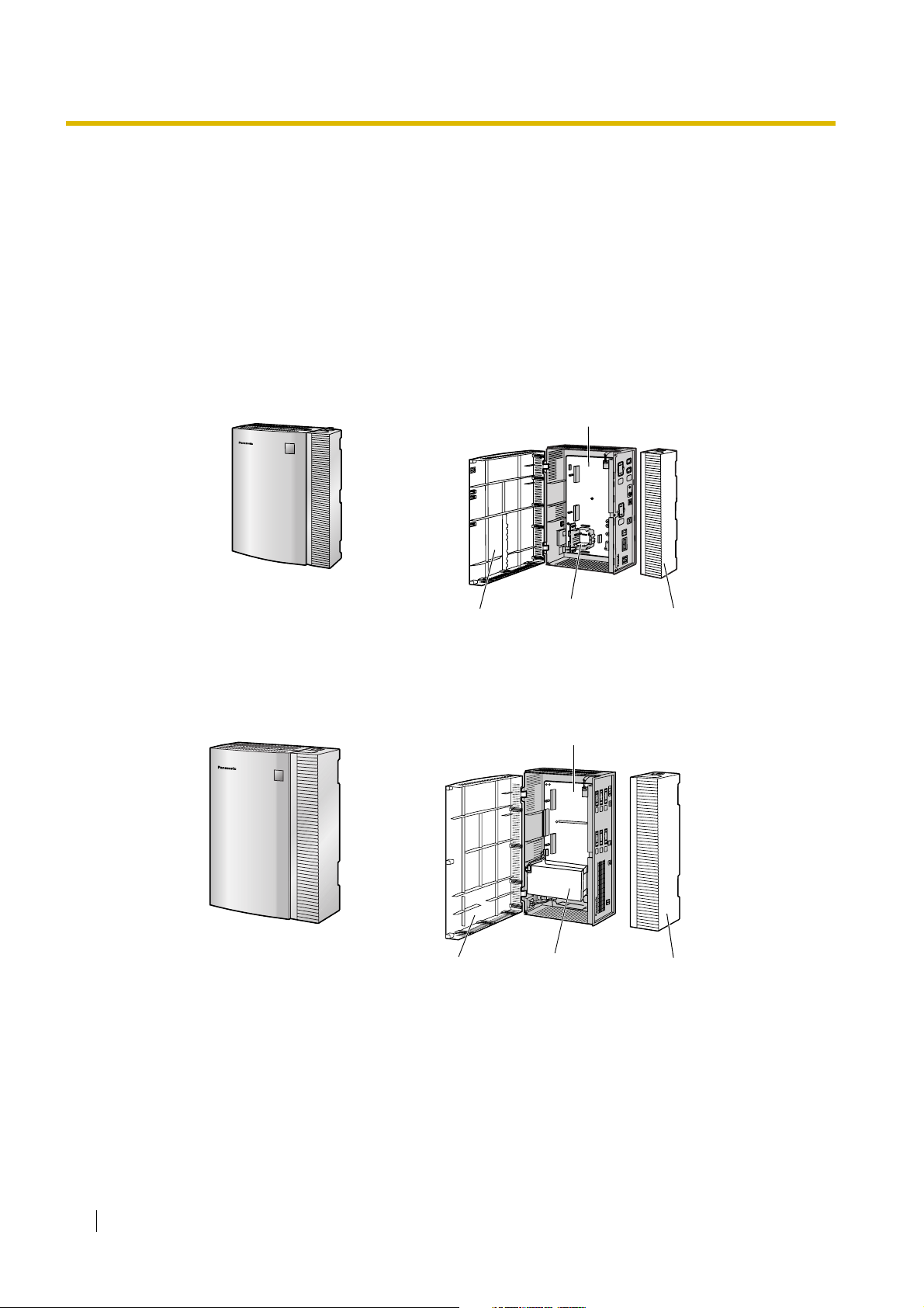
1.1.1 Main Unit
The KX-TVM50 is equipped with 2 jacks. Its flash memory card provides 4 hours of recording
capacity. The KX-TVM200/KX-NCV200 does not provide factory-installed jacks. Its hard disk drive
provides 1000 hours of recording capacity. Both systems can be expanded by adding optional service
cards.
KX-TVM50
Main Board
KX-TVM200/KX-NCV200
Front Cover
Front Cover
Factory-installed
Flash Memory Card
Main Board
3.5" Hard
Disk Drive
Cable Cover
Cable Cover
16 Installation Manual
Page 17
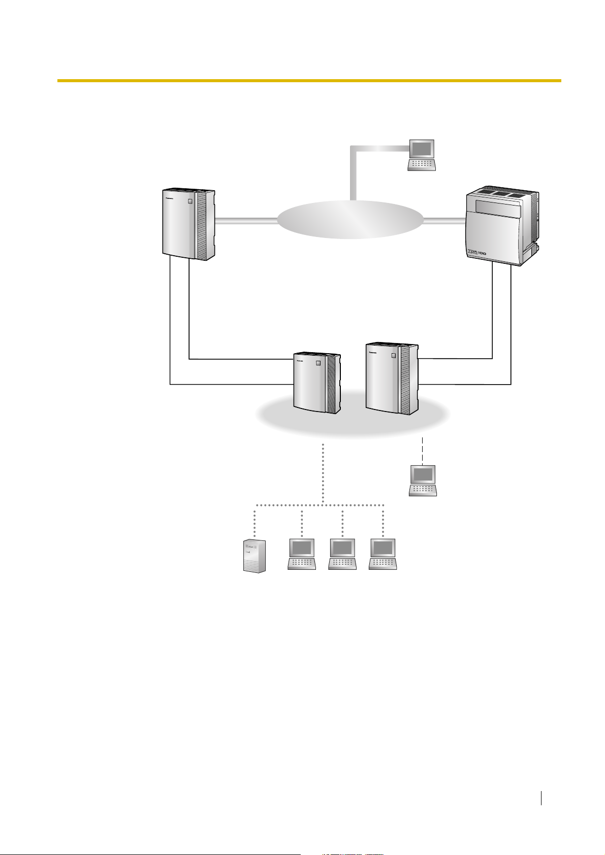
1.1.2 System Connection Diagram
Telephone Company Lines
1.1 Basic System Construction
Remote PC
PBXPBX
DPT/APT/Inband
Interface
Internal
Modem
Server PC
KX-TVM50
KX-TVM50
LAN
PC PC PC
KX-TVM200/KX-NCV200
KX-TVM200/KX-NCV200
PC
USB
DPT
Interface
Internal
Modem
Installation Manual 17
Page 18

1.1 Basic System Construction
1.1.3 Options
Optional Cards—KX-TVM50
Model Model Name Maximum Quantity
KX-TVM502 2-Port Hybrid Expansion Card 2
KX-TVM503 2-Port Digital Expansion Card 2
KX-TVM524 Memory Expansion Card 1
KX-TVM594 LAN Interface Card 1
KX-TVM296 Modem Card 1
Optional Cards—KX-TVM200/KX-NCV200
Model Model Name Maximum Quantity
KX-TVM204 4-Port Digital Expansion Card 6
KX-TVM296 Modem Card 1
1.1.4 Initial Configuration and Expansion Capabilities
Specification KX-TVM50
No. of Ports Initial Configuration 2 0
Maximum 6 24
Recording Time Initial Configuration 4 hours 1000 hours
Maximum 8 hours —
KX-TVM200/
KX-NCV200
18 Installation Manual
Page 19

1.1 Basic System Construction
1.1.5 Installer Equipment and Software Requirements
The installer must use a PC and the KX-TVM/NCV Maintenance Console software to configure and
customise the VPS. The PC can be connected via the built-in USB port of the VPS, or can access the
VPS over a local network via the built-in LAN port (KX-TVM200/KX-NCV200) or an optional LAN
Interface Card (KX-TVM50). Off-site programming is also possible provided an optional Modem Card
is installed in the VPS.
For more information, see Section 3, Installing KX-TVM/NCV Maintenance Console.
Installation Manual 19
Page 20

1.1 Basic System Construction
1.1.6 Recommendations for System Configuration
In order for the VPS to handle calls smoothly, generally there should be 1 VPS port for every 6 trunks
connected to the PBX. If Automated Attendant (AA) service is used, allotting 1 VPS port for every 4
trunks should be sufficient. If the PBX and VPS have heavy traffic and callers cannot reach the VPS
because of congestion, more VPS ports should be added.
Recommendations are outlined in the following charts.
KX-TVM50
PBX KX-TVM50
No. of Trunks
1–6 1–4 1
7–12 5–8 2
13–18 9–12 3
19–24 13–16 4
25–30 17–20 5
31–36 21–24 6
* The factory-installed jacks should be sufficient.
KX-TVM200/KX-NCV200
No. of Trunks
1–6 1–4 1
7–12 5–8 2
13–18 9–12 3
No. of Trunks When
Using AA Service
PBX KX-TVM200/KX-NCV200
No. of Trunks When
Using AA Service
No. of Ports
No. of Ports
No. of Optional Port
Cards
0*
1
2
No. of Optional Port
Cards
1
20 Installation Manual
19–24 13–16 4
25–30 17–20 5
31–36 21–24 6
2
37–42 25–28 7
43–48 29–32 8
49–54 33–36 9
55–60 37–40 10
3
61–66 41–44 11
67–72 45–48 12
Page 21

1.1 Basic System Construction
PBX KX-TVM200/KX-NCV200
No. of Trunks
No. of Trunks When
Using AA Service
No. of Ports
73–78 49–52 13
79–84 53–56 14
85–90 57–60 15
91–96 61–64 16
97–102 65–68 17
103–108 69–72 18
109–114 73–76 19
115–120 77–80 20
121–126 81–84 21
127–132 85–88 22
133–138 89–92 23
139–144 93–96 24
No. of Optional Port
Cards
4
5
6
Installation Manual 21
Page 22

1.1 Basic System Construction
1.1.7 Compatible PBXs
The VPS can be integrated with the following PBXs using the integration types listed below.
KX-TVM50
PBX Model Recommended Integration Type Other Integration Type
KX-TDA
Series
KX-TD816 DPT Integration Inband Integration
KX-TD1232 DPT Integration Inband Integration
KX-TD500 DPT Integration Inband Integration
KX-TD308 DPT Integration Inband Integration
KX-TD612 DPT Integration Inband Integration
KX-TA Series APT Integration Inband Integration
KX-TE Series
Third-party
Manufacturer
*1
For KX-TES824/TEM824, PBX software version 1.0.44 or later is required for APT Integration. Consult your
dealer for more information.
KX-TVM200/KX-NCV200
PBX Model Integration Type
KX-TDA Series
DPT Integration Inband Integration
APT Integration
*1
Inband Integration
Inband Integration or No Integration —
KX-TD816
KX-TD1232
KX-TD500
KX-TD308
KX-TD612
22 Installation Manual
DPT Integration
Page 23

1.2 Voice Mail Integration
1.2.1 Overview
In order for the VPS to function, it must be integrated with the PBX it is connected to. The type of
integration that is used determines how voice (caller messages, VPS prompts, etc.) and data
(extension status, button presses, etc.) are sent between the VPS and the PBX.
DPT Integration
When the VPS and PBX use DPT Integration, voices and data are sent digitally. The most significant
advantage of DPT Integration is that the 2B+D communication provides 2 VPS ports for each port.
DPT Integration requires the proper software level in the PBX as well as 4-conductor connections for
each jack. In order for the VPS to function properly using DPT Integration, the PBX and VPS must be
programmed to work together. For a list of PBXs that are compatible with DPT integration, see 1.1.7
Compatible PBXs.
To use DPT Integration, the lowest numbered jack of the VPS must be connected to the lowest
numbered jack assigned as a Voice Mail Port Assignment in the PBX. See the DPT connection
example(s) for your VPS model in the following sections:
1.2.2 Connection Examples—KX-TVM50
1.2.3 Connection Examples—KX-TVM200/KX-NCV200
Connect the other jacks to the VPS in the same order as they are found in Voice Mail Port Assignment
in the PBX.
1.2 Voice Mail Integration
APT Integration (TVM50 only)
When the VPS and PBX use APT Integration, voices are sent using analogue technology, and data
is sent digitally. APT Integration requires the proper software level in the PBX as well as 4-conductor
connections for each jack. In order for the VPS to function properly using APT Integration, the PBX
and VPS must be programmed to work together. For a list of PBXs that are compatible with APT
integration, see 1.1.7 Compatible PBXs.
Inband Integration (TVM50 only)
When the VPS and PBX use Inband Integration, voices are sent using analogue technology, and data
is sent using analogue DTMF tones.
No Integration (TVM50 only)
When the VPS and PBX use no integration, voices are sent using analogue technology and data is
sent to the VPS through the use of standard audio signals, such as DTMF tones, busy signals,
ringback tones, etc.
Installation Manual 23
Page 24
1.2 Voice Mail Integration
01
02
03
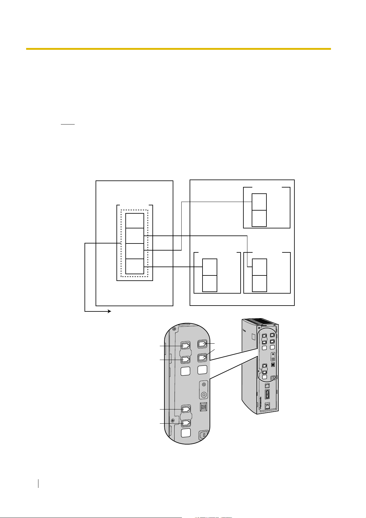
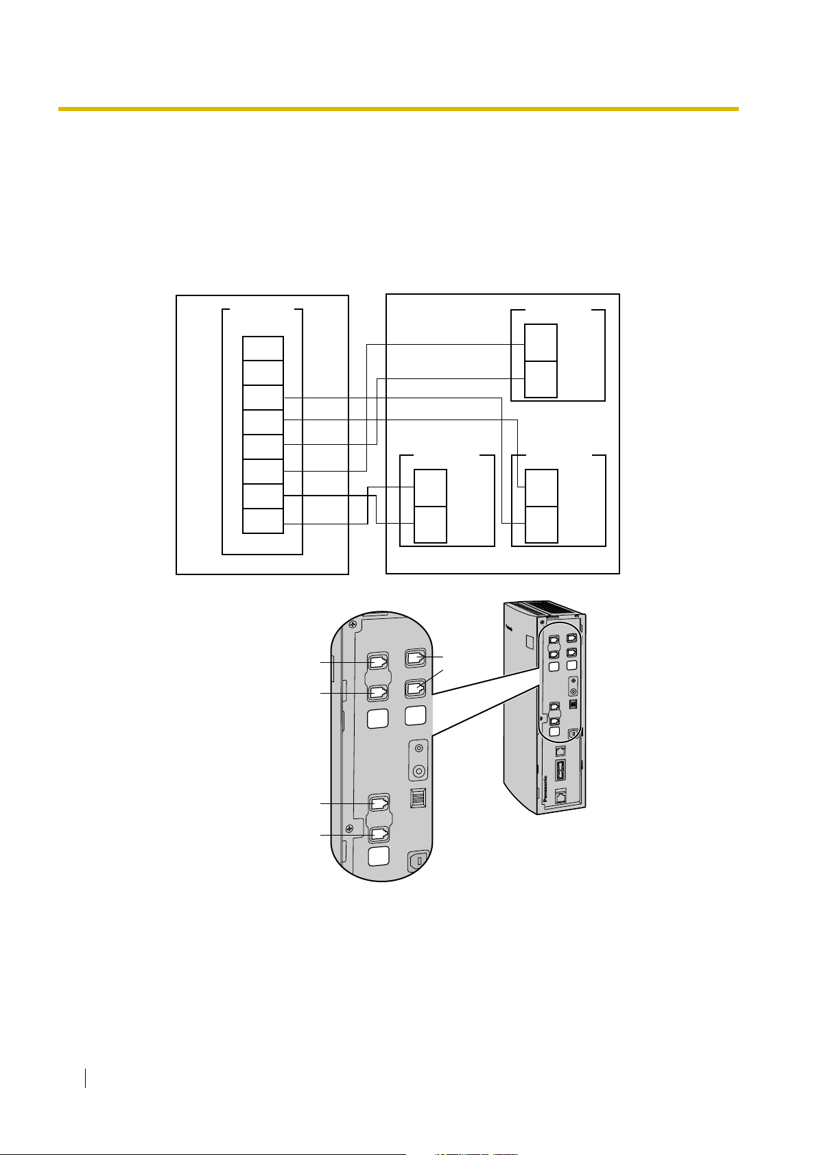
1.2.2 Connection Examples—KX-TVM50
DPT Integration
When using DPT Integration, VPS jacks are connected to the digital extension ports of the PBX. Note
that only odd numbered VPS jacks (1, 3, and 5) can be used. Each of these VPS jacks provides 2
VPS ports and can handle 1 call per port.
Note
• For DPT Integration, the lowest numbered jack of the VPS must be connected to the lowest
numbered port of the Voice Mail group assigned through PBX programming.
Connection Example (Factory-installed Jacks and KX-TVM502 × 2, DPT Integration Mode)
PBX (KX-TDA30)
DLC4 Card
Port 4
Port 3
Port 2
Port 1
Assigned as VM (DPT) ports
Jack 6
KX-TVM50
Factory- installed
Jacks
Port 1
Jack 1
Port 2
Jack 2
Slot 1
Jack 2
Jack 1
KX-TVM502
Port 3
Jack 3
Port 4
Jack 4
Slot 2
KX-TVM502
Port 5
Jack 5
Port 6
Jack 6
Slot 3
01
03
24 Installation Manual
Jack 5
02
Jack 4
Jack 3
Page 25
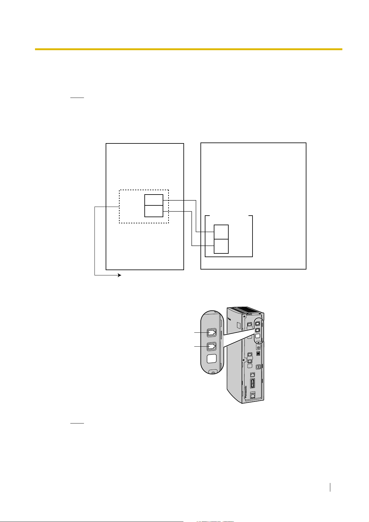
APT Integration
01
When using APT Integration, VPS jacks are connected to the hybrid extension jacks of the PBX. Each
VPS jack provides 1 VPS port and can handle 1 call per port.
Note
• Jack 1 must be connected to the PBX.
Connection Example (Factory-installed Jacks, APT Integration Mode)
1.2 Voice Mail Integration
PBX (KX-TE Series)
Jack 7
Jack 8
Assigned as VM1 APT ports
KX-TVM50
Factory- installed
Jacks
Jack 1
Port 1
Port 2
Jack 2
Slot 1
Jack 2
Jack 1
01
03
02
Note
• A maximum of 2 VPS jacks can be connected to the PBX.
Installation Manual 25
Page 26
1.2 Voice Mail Integration
01
02
03
Inband/No Integration
When using Inband/No Integration, VPS jacks are connected to the SLT ports of the PBX. Each VPS
jack provides 1 VPS port and can handle 1 call per port.
Connection Example (Factory-installed Jacks and KX-TVM502 × 2, Inband/No Integration
Mode)
PBX (KX-TDA30)
SLC8 Card
Port 8
Port 7
Port 6
Port 5
Port 4
Port 3
Port 2
Port 1
Jack 6
Port 1
Port 2
Slot 1
KX-TVM50
Jack 1
Jack 2
Jack 2
Jack 1
KX-TVM502
Port 3
Jack 3
Jack 4
Port 4
Slot 2
KX-TVM502 KX-TVM502
Port 5
Jack 5
Jack 6
Port 6
Slot 3
01
03
26 Installation Manual
Jack 5
02
Jack 4
Jack 3
Page 27
1.2 Voice Mail Integration
01
02
03
04
05
06
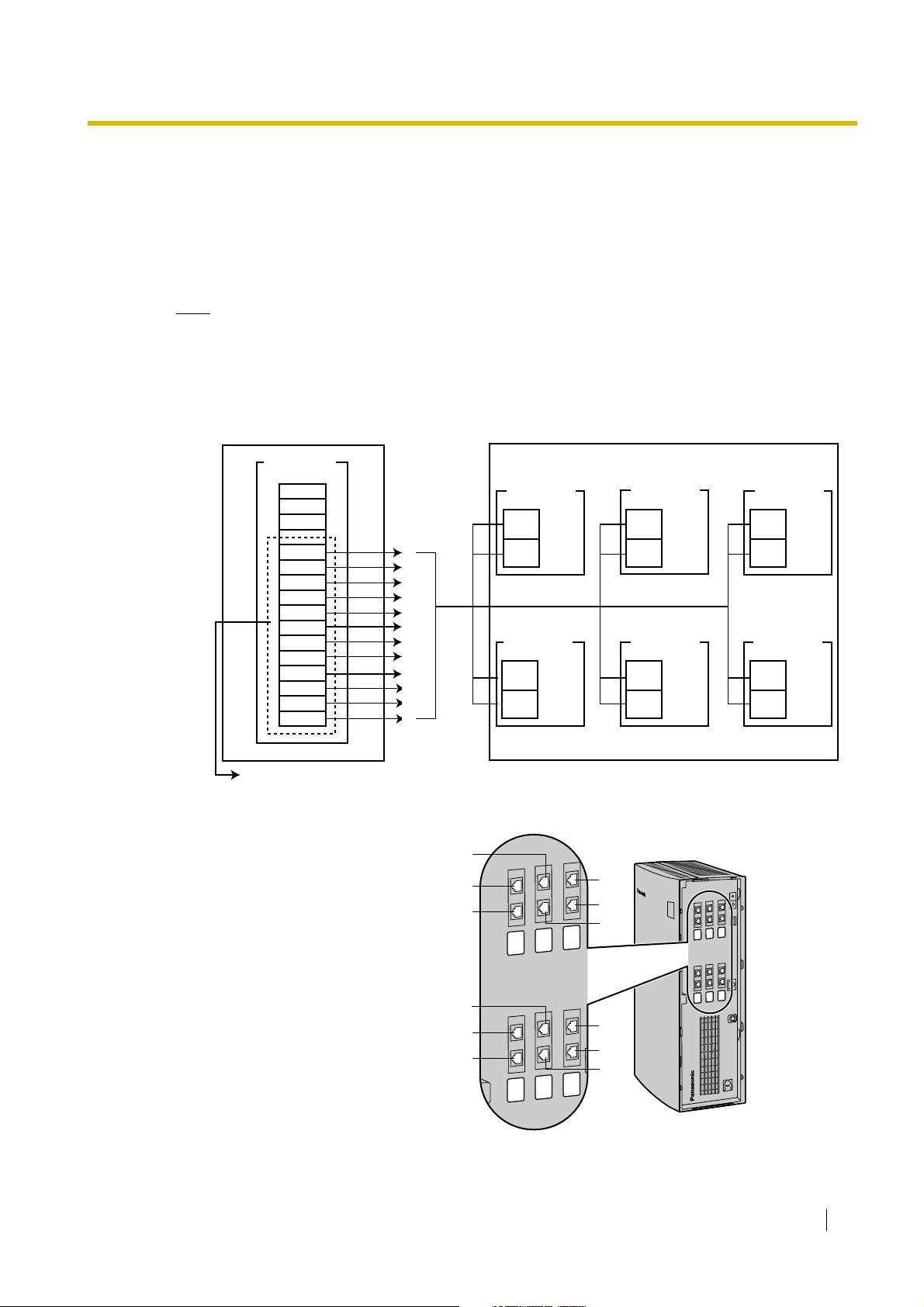
1.2.3 Connection Examples—KX-TVM200/KX-NCV200
DPT Integration
The KX-TVM200/KX-NCV200 supports DPT Integration only, therefore it must be connected to the
digital extension ports of the PBX. Each VPS jack provides 2 VPS ports and can handle 1 call per
port.
Note
• For DPT Integration, the lowest numbered jack of the VPS must be connected to the lowest
numbered port of the Voice Mail group assigned through PBX programming.
Connection Example (KX-TVM204 × 6, DPT Integration Mode)
PBX (KX-TDA100)
DLC16 Card
Port 16
Port 15
Port 14
Port 13
Port 12
Port 11
Port 10
Port 9
Port 8
Port 7
Port 6
Port 5
Port 4
Port 3
Port 2
Port 1
To KX-TVM200/
KX-NCV200 Jack
12
11
10
9
8
7
6
5
4
3
2
1
Assigned as VM (DPT) ports
Jack 8
Jack 12
Jack 11
Slot 1
KX-TVM204
Port 1
Jack 1
Port 2
Port 3
Jack 2
Port 4
KX-TVM204
Port 5
Jack 3
Port 6
Port 7
Jack 4
Port 8
Slot 2
KX-TVM200/KX-NCV200
Slot 3
KX-TVM204
Port 9
Jack 5
Port 10
Port 11
Jack 6
Port 12
KX-TVM204
Port 13
Jack 7
Port 14
Port 15
Jack 8
Port 16
Slot 4
Jack 4
Jack 3
Jack 7
02
04
06
Slot 5
KX-TVM204
Port 17
Jack 9
Port 18
Port 19
Jack 10
Port 20
KX-TVM204
Port 21
Jack 11
Port 22
Port 23
Jack 12
Port 24
Slot 6
01
03
Jack 6
Jack 10
Jack 9
Jack 2
Jack 1
Jack 5
05
Installation Manual 27
Page 28

1.3 Specifications
1.3 Specifications
Specification KX-TVM50 KX-TVM200/KX-NCV200
Hardware Available Port Cards 2-Port Hybrid Expansion Card
(KX-TVM502)
2-Port Digital Expansion Card
(KX-TVM503)
Number of Port Card Slots 2 6
Data Ports USB (built-in)
LAN (optional)
Modem (optional)
Additional Hardware Mode Switch
Telephone Line
Connections
Message Recording
Medium
Recording Capacity
Main CPU 32-bit microprocessor
Compression Rate 32 Kbps
Internal Modem Type V.90
• APT/DPT Integration:
4-conductor cable
• Inband/No Integration:
2-conductor cable
Flash Memory
4 h (expandable to 8 h)
4-Port Digital Expansion
Card (KX-TVM204)
USB (built-in)
LAN (built-in)
Modem (optional)
4-conductor cable
Internal Hard Disk Drive
(HDD)
*1
1000 h
Dialling Method DTMF
Flash Time 100 ms/300 ms/600 ms/900 ms
(programmable)
CPC Detection None/6.5 ms/150 ms/300 ms/450 ms/
600 ms (programmable)
Line Type • Loop start minimum Loop
Current: 20 mA
• Minimum Line Voltage: 7 V DC
• Minimum Ringing Voltage: 40 V
AC
Extension Numbering 2 to 5 digits (programmable)
Pause Length 100 ms to 9900 ms (programmable)
Message Waiting Lamp • APT/DPT Integration: Data Line
of APT/DPT Interface
• Inband Integration:
Programmable DTMF sequence
Data Line of DPT Interface
–
–
–
28 Installation Manual
Page 29

Specification KX-TVM50 KX-TVM200/KX-NCV200
C˚C
Software Custom Services Up to 100
Number of Messages Unlimited
1.3 Specifications
Length of Personal
Greeting Message
Message Retention Time 1 to 30 days, unlimited (programmable)
Maximum Message Length 1 to 60 min, unlimited (programmable)
Maximum Combined
Length of Messages per
Mailbox
No. of Mailboxes 62 Subscriber + 2 Manager 1022 Subscriber + 2
Reports Mailbox Information, Call Account,
Environment Environmental
Requirements
Power Source 100 V AC to 240 V AC, 0.25 A,
Up to 360 s (programmable)
1 to 600 min, unlimited (programmable)
Port Usage, Memory Usage, Mailbox
Usage, Fax Call, Call Handling
Statistic, Custom Service, Message
Status, Subscriber Setup, Security
Information, Hourly Statistics, E-mail
˚
5 to 40
50 Hz/60 Hz
Manager
Mailbox Information, Call
Account, Port Usage, HDD
Usage, Mailbox Usage, Fax
Call, Call Handling Statistic,
Custom Service, Message
Status, Subscriber Setup,
Security Information,
Hourly Statistics, E-mail
Refer to "Environmental
Requirements", 2.1 Before
Installation
100 V AC to 240 V AC, 1.5
A, 50 Hz/60 Hz (Panasonic
AC adaptor, PSLP1244) or
110 V AC to 240 V AC, 1.35
A, 50 Hz/60 Hz (Panasonic
AC adaptor, PSLP1434)
DC Input 9 V, 0.75 A (6.75 W) 40 V, 1.38 A (55.2 W)
Dimensions (W × H × D) 249 mm (W) × 316 mm (H)
× 73 mm (D)
Weight (when all available
option cards are installed)
*1
The recording capacity specification shown here for the KX-TVM50 applies to when 1 System Prompt language is installed. Recording
capacity is reduced by about 1 hour for each additional System Prompt language that is installed.
No more than 1.7 kg No more than 4.0 kg
275 mm (W) × 376 mm (H)
× 117 mm (D)
Installation Manual 29
Page 30

1.3 Specifications
30 Installation Manual
Page 31

Section 2
Installation
This section explains how to install the VPS and its optional
cards.
Installation Manual 31
Page 32

2.1 Before Installation
2.1 Before Installation
Please read the following precautions before installing the VPS.
Installation Precautions
The VPS should be wall-mounted. Improper placement of the system may result in malfunction,
noise, or discolouration. Avoid installing the VPS in the following places:
• in direct sunlight; in hot, cold, or humid places
• in areas where sulphuric gas can damage the equipment (e.g., areas near thermal springs, etc.)
• where shocks or vibrations are frequent or strong
• in dusty places or places where water or oil may come in contact with the unit
• near high frequency generating devices such as sewing machines, elevators or electric welders
• on or near computers or other office equipment, microwave ovens, or air conditioners (Ideally,
the VPS should not be installed in the same room with any of these items, and should be at least
2 m away from televisions.)
Do not obstruct the areas around the PBX and the VPS. Both require open space above the unit
for cooling and space on the sides for maintenance and inspection.
Wiring Precautions
Be sure to follow these instructions when wiring.
• Do not wire the telephone cable parallel to an AC power source, computer, etc. If cables are run
near those wires, shield them with metal tubing or use shielded cables and earth the shields.
• Use protectors if running cables on the floor. Avoid running cables under carpets.
• Avoid sharing the power supply to the VPS with computers or other office equipment. Induction
noise from such equipment may interrupt the VPS operation.
When making any connections or removing the cover, be sure the power switch is turned off.
When installing telephone wiring, basic safety precautions should always be followed to reduce the
risk of fire, electric shock and injury to persons, including the following:
• Never install telephone wiring during a lightning storm.
• Never install telephone jacks in wet locations unless the jack is specifically designed for wet
locations.
• Never touch uninsulated telephone wires or terminals unless the telephone line has been
disconnected at the network interface.
• Use caution when installing or modifying telephone lines.
Note
• If you live in an area that has frequent power failures, we strongly recommend connecting
the VPS and PBX to an uninterruptible power supply (UPS). Use only a UPS which can
provide adequate power supply to all connected devices. Refer to the specifications for the
power rating of your VPS and PBX.
32 Installation Manual
Page 33

2.1 Before Installation
C˚C
Environmental Requirements (KX-TVM200/KX-NCV200 only)
The hard disk drive is sensitive to cold, heat, dryness, humidity, shock, vibration, and magnetic fields.
Please observe the conditions specified below.
Hard Disk Drive Usage Environment
Operating Temperature:
˚
5 to 40
Operating Humidity: See the graph below.
Shock: Under 5 G
Vibration: 5 Hz to 22 Hz : 0.0042 cm displacement; double amplitude,
23 Hz to 350 Hz : Under 0.5 G
Magnetic Field: DC : 0.6 mT
to 700 kHz : 0.7 µT
700 kHz to 1.5 MHz : 3 µT
Allowable Relative Humidity vs. Temperature
Relative Humidity (%)
100
90
80
70
1 octave per minute.
60
50
40
30
20
10
0
Temperature
Operating Area
5515 35 45255 (˚C)
Installation Manual 33
Page 34

2.1 Before Installation
Necessary Tools (not supplied)
Twisted pair 4-conductor cables are needed for connecting the VPS to the PBX. For the KX-TVM50,
twisted pair 2-conductor cables are needed if using Inband or None Integration.
A USB cable is needed when connecting the VPS to the PC that will used for programming via the
KX-TVM/NCV Maintenance Console.
34 Installation Manual
Page 35

2.2 Unpacking
The following items are included with the VPS.
Main Unit 1 1
AC Adaptor 1 1
AC Cord 1 1
Screws (Wall Mounting) 5 5
Washers (Wall Mounting) 5 5
Cable strap 1 1
CD-ROM 1 1
2.2 Unpacking
KX-TVM50 KX-TVM200/KX-NCV200
Installation Manual 35
Page 36

2.3 Names and Locations
2.3 Names and Locations
Outside/Inside View
KX-TVM50
1
2
4
10
11
5
6
7
8
9
12
13
14
3
1.
Run Indicator
2. Alarm Indicator
3. Dummy Cover Plates (for Port Card Slots 2 and 3)
4. Factory-installed Jacks
5. Reset Button
6. Shutdown Button
7. Mode Switch
8. USB Port
9. Dummy Cover Plate (for LAN Interface Card)
10. Dummy Cover Plate (Reserved)
11. Dummy Cover Plate (for Modem Card)
12. Earth Terminal
13. DC IN
14. Power Switch
Front Cover
36 Installation Manual
Main Board
Factory-installed
Flash Memory Card
Cable Cover
Page 37

KX-TVM200/KX-NCV200
1
2
3
2.3 Names and Locations
4
5
6
7
8
10
11
12
1.
Run Indicator
9
2. Alarm Indicator
3. Dummy Cover Plates (for Port Card Slots 1 to 6)
4. Reset Button
5. Shutdown Button
6. Mode Switch
7. LAN Port
8. USB Port
9. Dummy Cover Plate (for Modem Card)
10. Earth Terminal
11. DC IN
12. Power Switch
Main Board
Front Cover
3.5" Hard
Disk Drive
Cable Cover
Installation Manual 37
Page 38

2.3 Names and Locations
System Components
Run Indicator
Lights during normal operation; flashes when the system is off-line and cannot receive calls.
Alarm Indicator
Flashes when a system error is detected or while the VPS is preparing to shutdown. Lights when the
shutdown procedure is complete.
Reset Button
Resets the VPS.
Note
• Make sure the VPS is not in use before pressing the Reset Button.
Shutdown Button
Initiates the shutdown procedure. When the Alarm Indicator lights after pressing the Shutdown
Button, you may safely turn off the power switch.
Note
• Make sure the VPS is not in use before pressing the Shutdown Button.
Mode Switch
Used to perform one of several administration/service operations by selecting one of 16 switch
positions. After setting the Mode Switch to the appropriate position, shut down and restart the VPS.
Change the position of the switches by using the tip of a pointed object, such as a pen.
The available Mode Switch positions are shown in the following table. The black area in the switch
illustration indicates the direction of the switch.
0 Puts the VPS in normal mode.
1 Reserved
2
3
4 Reserved
5
Switch Position Operation
1234
0
1
0
1
0
1
0
1
1234
1234
1234
Puts the VPS in DPT Integration mode. Auto Configuration starts and all
ports are set to provide Automated Attendant service.
Puts the VPS in DPT Integration mode. Auto Configuration starts and all
ports are set to provide Voice Mail service.
Initialises the VPS. All settings are reset to their default values. Recorded
messages are erased. System Prompts (including customised prompts)
are preserved.
6
38 Installation Manual
0
1
1234
KX-TVM200/KX-NCV200 only
Puts the VPS in hard disk test mode.
Page 39

Switch Position Operation
2.3 Names and Locations
7
0
1
1234
KX-NCV200 only
Initialises all ACD Report settings.
KX-TVM200/KX-NCV200 only
Initialises the VPS. For KX-NCV200, ACD Report settings are also
initialised. All settings are reset to their default values. Recorded
8
1234
0
1
messages and customised prompts are erased. All System Prompts
are reset to their defaults.
CAUTION
All user-recorded prompts are erased.
9Reserved
KX-TVM50 only
Puts the VPS in APT Integration mode. Auto Configuration starts and all
ports are set to provide Automated Attendant service.
KX-TVM50 only
Puts the VPS in APT Integration mode. Auto Configuration starts and all
ports are set to provide Voice Mail service.
Primary Language will be set to use Language 1 prompts.*
10
11
12
1234
0
1
1234
0
1
1234
0
1
1
13
14
1234
0
1
1234
0
1
Primary Language will be set to use Language 2 prompts.*
Primary Language will be set to use Language 3 prompts.*
1
1
15 Reserved
1
If the selected language has no prompts, no prompts will be heard.
*
When setting the Mode Switch to any position (except 0):
1. Disconnect the port cables from the VPS.
2. Turn the power switch off.
3. Set the Mode Switch.
4. Turn the power switch back on.
5. Connect the port cables.
6. Confirm that the Run Indicator blinks the same number of times as the Mode Switch position
(e.g., 5 blinks for switch position 5, etc.).
• This may take several minutes. The Alarm Indicator and Run Indicator will first blink
intermittently before the Run Indicator blinks to indicate the Mode Switch position.
7. Turn the power switch off at the VPS.
8. Set the Mode Switch to position 0.
9. Turn the power switch back on at the VPS.
Installation Manual 39
Page 40

2.3 Names and Locations
LAN Port (Optional for KX-TVM50)
Used to access the VPS over an Ethernet network.
USB Port
Used to access the VPS via USB.
Earth Terminal
Must be connected to an earth source with less than 1 resistance.
DC IN
Used to supply power to the VPS from the AC Adaptor.
Power Switch
Starts the system and begins the self-test.
SAFETY PRECAUTION: When making any connections or removing the cover, be sure the
power switch is turned off.
Factory Installed Flash Memory Card (KX-TVM50 only)
Stores all system programming and system prompts, and allows up to 4 hours of message recording
time.
Hard Disk Drive (KX-TVM200/KX-NCV200 only)
Stores all system programming and system prompts, and allows up to 1000 hours of message
recording time.
Note
• The actual hard disk drive mounted on your VPS may look different from the ones illustrated
in this manual.
40 Installation Manual
Page 41

2.4 Installation Overview
The following is an overview of the steps needed to install optional cards and prepare the VPS
hardware for use. Once hardware installation is complete, see Customising the System for
instructions on software setup and VPS customisation.
CAUTION
The information below is only intended as an overview of the installation process. When installing
the VPS, refer to the sections listed below for detailed instructions.
1. Open the covers (see 2.5 Opening/Closing the Covers).
2. Remove the Dummy Cover Plates (see 2.6 Removing the Dummy Cover Plates).
3. Install the optional cards (see 2.7 Installing Optional Cards—KX-TVM50 or 2.8 Installing Optional
Cards—KX-TVM200/KX-NCV200).
4. Connect the VPS to the appropriate extension ports of the PBX (see 1.2.2 Connection
Examples—KX-TVM50 or 1.2.3 Connection Examples—KX-TVM200/KX-NCV200). Use 4conductor or 2-conductor cable as necessary (see 2.9 PBX Connections).
5. Connect the VPS to the PC to be used for programming (see 2.10 PC Connection).
6. Connect the VPS to earth (see 2.11 Frame Earth Connection).
7. Connect the AC adaptor to the VPS and to the power outlet (see 2.12 Connecting the AC
Adaptor).
2.4 Installation Overview
CAUTION
The power cord is the main disconnect device. Make sure that the power outlet is located near
the VPS and is easily accessible.
8. Secure the cables (see 2.13 Securing the Cables).
9. Initialise the VPS (see 2.14 Initialising the VPS During Installation).
10. Close the covers (see 2.5 Opening/Closing the Covers).
11. Wall mount the VPS and AC adaptor (see 2.15 Wall Mounting).
CAUTION
To turn off the power on the VPS, first press the Shutdown button, wait for the Alarm
Indicator to light, then turn off the power switch. Turning off the power switch before the
Alarm Indicator lights may cause the VPS to take an exceptionally long time (up to 10
minutes) to start up the next time the power is turned on.
Installation Manual 41
Page 42

2.5 Opening/Closing the Covers
2.5 Opening/Closing the Covers
The model shown here is the KX-TVM200/KX-NCV200, however this procedure is the same for the
KX-TVM50.
Opening the Covers
1. Push the release button in the direction shown below (1), and slide the cable cover in the
direction shown below (2). Turn the cable cover away from the unit and remove it.
Release Button
2. Remove the 3 screws.
1
Cable Cover
Screw
42 Installation Manual
Page 43

2.5 Opening/Closing the Covers
3. While holding both tabs located on the sides of the front cover, swing the cover open as shown.
Removing/Attaching the Front Cover
You may also detach the front cover from its hinges.
Removing the Front Cover
While holding the front cover open at a 45 angle, lift the cover away from the unit as shown.
˚
Installation Manual 43
Page 44

2.5 Opening/Closing the Covers
Attaching the Front Cover
Fit the front cover to the main unit as shown below, then close the front cover.
Closing the Covers
1. Close the front cover, then tighten the 3 screws.
Screw
44 Installation Manual
Page 45

2.5 Opening/Closing the Covers
2. Attach the rear hooks on the cable cover to the main unit, then swing the cable cover closed so
that the front hooks fit in place.
3. Slide the cable cover down until it locks.
Installation Manual 45
Page 46

2.6 Removing the Dummy Cover Plates
2.6 Removing the Dummy Cover Plates
Before installing optional cards, cut and remove the appropriate dummy cover plates from the main
unit using cutting pliers, as shown below.
The model shown here is the KX-TVM200/KX-NCV200, however this procedure is the same for the
KX-TVM50.
Dummy Cover Plate
CAUTION
For safety reasons, smooth the cut edges after removing the dummy cover plates.
46 Installation Manual
Page 47

2.7 Installing Optional Cards—KX-TVM50
2.7 Installing Optional Cards—KX-TVM50
The KX-TVM50 can be expanded by installing the following optional cards.
Model Model Name Maximum Quantity
KX-TVM502 2-Port Hybrid Expansion Card 2
KX-TVM503 2-Port Digital Expansion Card 2
KX-TVM524 Memory Expansion Card 1
KX-TVM594 LAN Interface Card 1
KX-TVM296 Modem Card 1
CAUTION
Before installing optional cards, it is very important that the power to the unit be turned
off. Before touching the optional cards or any components within the unit, discharge any
static electricity from your body by touching the earth terminal (if it is connected to earth)
or by using an earthing strap (user-supplied). This is a critical step that must be
performed to protect the circuit board and other components from damage caused by
static electricity.
Installation Manual 47
Page 48

2.7 Installing Optional Cards—KX-TVM50
2.7.1 2-Port Hybrid Expansion Card (KX-TVM502)
Each KX-TVM502 adds 2 ports to the VPS which can be used for DPT, APT, Inband, or No
Integration. KX-TVM502 cards can be installed in slots 2 and 3 of the VPS.
Integration Type
DPT Integration 1 2 3 (1 per card) 6
APT Integration 2 2 6 6
Inband/No
Integration
* When using DPT Integration, only odd numbered jacks (1, 3, and 5) can be used. Each jack
provides 2 VPS ports.
Included Items
Screws × 2
Installation
1. Position the front of the card so that the jacks fit in the open slot. Holding the card firmly in place,
lower the other end of the card so that the card's hole fits over the extension bolt.
CAUTION
When installing optional cards, do not put pressure on the main board. Doing so may result in
damage to the VPS.
Basic Configuration
No. of Useable
Jacks*
2266
No. of Ports
Maximum Configuration
KX-TVM502 x 2
No. of Useable
Jacks*
No. of Ports
Extension Bolt
48 Installation Manual
1
2
Page 49

2. Insert and tighten the screws as shown.
Note
• The KX-TVM502 operates at SELV.
2.7 Installing Optional Cards—KX-TVM50
Screw
Installation Manual 49
Page 50

2.7 Installing Optional Cards—KX-TVM50
2.7.2 2-Port Digital Expansion Card (KX-TVM503)
Each KX-TVM503 adds 2 ports to the VPS which can be used for DPT Integration.
KX-TVM503 cards can be installed in slots 2 and 3 of the VPS.
Integration Type
DPT Integration 1 2 3 (1 per card) 6
Included Items
Screws × 2
Installation
1. Position the front of the card so that the jacks fit in the open slot. Holding the card firmly in place,
lower the other end of the card so that the card's hole fits over the extension bolt.
CAUTION
When installing optional cards, do not put pressure on the main board. Doing so may result in
damage to the VPS.
Basic Configuration
No. of Jacks No. of Ports No. of Jacks No. of Ports
1
Maximum Configuration
KX-TVM503 x 2
Extension Bolt
2
50 Installation Manual
Page 51

2. Insert and tighten the screws as shown.
Note
• The KX-TVM503 operates at SELV.
2.7 Installing Optional Cards—KX-TVM50
Screw
Installation Manual 51
Page 52

2.7 Installing Optional Cards—KX-TVM50
2.7.3 Memory Expansion Card (KX-TVM524)
The KX-TVM524 adds an additional 4 hours of recording time to the VPS.
Included Items
None
Installation
1. Insert the card between the guide rails and slide it down as shown.
2. Secure the latch by flipping it toward the centre of the card and slightly pressing down on it.
CAUTION
When installing optional cards, do not put pressure on the main board. Doing so may result in
damage to the VPS.
52 Installation Manual
Page 53

2.7.4 LAN Interface Card (KX-TVM594)
The KX-TVM594 allows the VPS to be accessed over a local area network (LAN) for administration
purposes.
Included Items
Screw × 1
Installation
1. Insert the card between the guide rails and slide it down as shown.
2. Secure the latch by flipping it toward the centre of the card and slightly pressing down on it.
CAUTION
When installing optional cards, do not put pressure on the main board. Doing so may result in
damage to the VPS.
2.7 Installing Optional Cards—KX-TVM50
Installation Manual 53
Page 54

2.7 Installing Optional Cards—KX-TVM50
3. Insert and tighten the screw as shown.
Screw
54 Installation Manual
Page 55

2.7.5 Modem Card (KX-TVM296)
The KX-TVM296 allows the VPS to be accessed remotely for administration purposes.
Included Items
Screw × 1
Installation
1. Insert the card between the guide rails and slide it down as shown.
2. Secure the latch by flipping it toward the centre of the card and slightly pressing down on it.
CAUTION
When installing optional cards, do not put pressure on the main board. Doing so may result in
damage to the VPS.
2.7 Installing Optional Cards—KX-TVM50
Installation Manual 55
Page 56

2.7 Installing Optional Cards—KX-TVM50
3. Insert and tighten the screw as shown.
Screw
Note
• The KX-TVM296 operates at TNV.
56 Installation Manual
Page 57

2.8 Installing Optional Cards—KX-TVM200/KX-NCV200
2.8 Installing Optional Cards—KX-TVM200/KXNCV200
The KX-TVM200/KX-NCV200 can be expanded by installing the following optional cards.
Model Model Name Maximum Quantity
KX-TVM204 4-Port Digital Expansion Card 6
KX-TVM296 Modem Card 1
CAUTION
Before installing optional cards, it is very important that the power to the unit be turned
off. Before touching the optional cards or any components within the unit, discharge any
static electricity from your body by touching the earth terminal (if it is connected to earth)
or by using an earthing strap (user-supplied). This is a critical step that must be
performed to protect the circuit board and other components from damage caused by
static electricity.
Installation Manual 57
Page 58

2.8 Installing Optional Cards—KX-TVM200/KX-NCV200
2.8.1 4-Port Digital Expansion Card (KX-TVM204)
Each KX-TVM204 adds 4 ports to the VPS which can be used for DPT Integration. KX-TVM204 cards
can be installed in slots 1 to 6 of the VPS.
Integration Type
DPT Integration 0 0 12 24 (2 per jack)
Included Items
Extension Bolt × 3, Screw × 3
Installation
1. Position the front of the card so that the jacks fit in the open slot. Make sure that the tabs on both
sides of the card fit into place. Holding the card firmly in place, lower the other end of the card so
that the card's hole fits over the extension bolt.
CAUTION
When installing optional cards, do not put pressure on the main board. Doing so may result in
damage to the VPS.
Basic Configuration
No. of Jacks No. of Ports No. of Jacks No. of Ports
Maximum Configuration
(KX-TVM204 x 6)
Extension Bolt
58 Installation Manual
1
2
Page 59

2.8 Installing Optional Cards—KX-TVM200/KX-NCV200
2. Insert the new extension bolts (included with the card) into the holes on the card, and tighten
them to secure the card.
Extension Bolt
Installation Manual 59
Page 60

2.8 Installing Optional Cards—KX-TVM200/KX-NCV200
Installing Cards in Slot 5 or Slot 6
When installing a card in Slot 5 or 6, secure the card using the screws included with the card, instead
of the extension bolts.
Note
• The KX-TVM204 operates at SELV.
Screw
60 Installation Manual
Page 61

2.8.2 Modem Card (KX-TVM296)
The KX-TVM296 allows the VPS to be accessed remotely for administration purposes.
Included Items
Screw × 1
Installation
1. Insert the card between the guide rails and slide it down as shown.
CAUTION
When installing optional cards, do not put pressure on the main board. Doing so may result in
damage to the VPS.
2.8 Installing Optional Cards—KX-TVM200/KX-NCV200
2. Insert and tighten the screw as shown.
Screw
Note
• The KX-TVM296 operates at TNV.
Installation Manual 61
Page 62

2.9 PBX Connections
2.9 PBX Connections
2.9.1 Connecting to the PBX
One jack of the VPS can be connected to 1 jack of the PBX. For APT/DPT Integration, use a 4conductor cable to connect the VPS and PBX. For Inband or None Integration (KX-TVM50 only), use
a 2-conductor (T and R) cable.
4-Conductor Cable
Y
G
R
B
Modular Connection
B: BLACK
R: RED
G: GREEN
Y: YELLOW
Outer Pins
Inner Pins
Y
G
R
B
RJ-11
Terminal wire
L5
T4
R3
H2
RJ-11
62 Installation Manual
Page 63

2.9.2 Modular Plug Connection
01
02
03
01
02
03
04
05
06
Insert the modular plug of each telephone cord into an available modular jack of the VPS.
Note
• When the VPS and PBX use APT or DPT Integration, use 0.5 mm telephone cords.
The maximum length of each telephone cord connecting the VPS and PBX should be under
100 m.
KX-TVM50
2.9 PBX Connections
01
03
02
KX-TVM200/KX-NCV200
02
04
06
01
03
05
Installation Manual 63
Page 64

2.10 PC Connection
2.10 PC Connection
A PC connected to the VPS can be used to program various VPS settings.
2.10.1 USB Connection
An on-site PC can be connected to the VPS via USB.
KX-TVM50
Note
• We recommend using a USB cable of no more than 5 m in length.
KX-TVM200/
KX-NCV200
To USB port
PC
64 Installation Manual
Page 65

2.10.2 LAN Connection
An on-site PC can be connected to the VPS over a local area network (LAN). For the KX-TVM50, an
optional LAN Interface Card must be installed in the VPS.
2.10 PC Connection
PC
KX-TVM50
Note
• Use a category 5 cross cable (user-supplied) when connecting the VPS to a switching hub.
KX-TVM200/
KX-NCV200
2.10.3 Modem Connection
To connect an off-site PC to the VPS remotely via modem, an optional Modem Card must be installed
in the VPS and the off-site PC must also be equipped with a modem.
Switching Hub
To network port
PC
PC
KX-TVM50
KX-TVM200/
KX-NCV200
Telephone
Company
CO
PBX
Extension
To Modem
PC
Installation Manual 65
Page 66

2.10 PC Connection
Note
• Do not connect the modem directly to the network. Connect the modem to the PBX as you
would a standard single line telephone (SLT). Off-site programming is possible if trunk (CO
line) calls from the remote PC are routed to the extension port connected to the VPS
modem. Note that the effective data transfer rate of the internal modem (maximum 33 600
bps) will be subject to the throughput limitations of the PBX.
66 Installation Manual
Page 67

2.11 Frame Earth Connection
IMPORTANT
Connect the frame of the main unit to earth. The earthing plug of the AC cable provides
some protection from external noise and lightning strikes, but it may not be enough to
fully protect the unit. A permanent connection between earth and the earth terminal of the
unit must be made.
1. Loosen the screw.
2. Insert an earthing wire (user-supplied).
Note
• Green-and-yellow insulation is required, and the cross-sectional area of the conductor must
be more than 0.75 mm
3. Tighten the screw.
4. Connect the earthing wire to earth.
2
or 18 AWG.
2.11 Frame Earth Connection
KX-TVM50
Earthing
wire
To earth
KX-TVM200/KX-NCV200
Earthing
wire
To earth
Screw
Screw
Note
• Be sure to comply with applicable local regulations (e.g., laws, guidelines).
• Proper connection to earth is very important to protect the unit from external noise, and can
reduce the risk of electrocution in the event of a lightening strike.
Installation Manual 67
Page 68

2.12 Connecting the AC Adaptor
2
2.12 Connecting the AC Adaptor
1. Plug the DC connector of the AC adaptor into DC IN.
KX-TVM50
DC IN
DC Connector
1
AC Adaptor
KX-TVM200/KX-NCV200
DC IN
DC Connector
AC Adaptor
2
1
68 Installation Manual
Page 69

2.12 Connecting the AC Adaptor
2. Confirm that the VPS power switch is in the "OFF" position, then plug the AC cord into the AC
adaptor, then plug the other end into an AC outlet.
AC Adaptor
AC Cord
To AC outlet
IMPORTANT
KX-TVM50: Use only the included Panasonic AC adaptor, part number PSLP1322.
KX-TVM200/KX-NCV200: Use only the included Panasonic AC adaptor, part number
PSLP1244 or PSLP1434.
Installation Manual 69
Page 70

2.13 Securing the Cables
2.13 Securing the Cables
The model shown here is the KX-TVM200/KX-NCV200, however this procedure is the same for the
KX-TVM50.
1. Attach the included strap to either of the 2 rails depending on your preference.
Rail
Rail
2. Bind the cables as shown.
70 Installation Manual
Page 71

3. Attach the cable cover (2.5 Opening/Closing the Covers).
Cable Cover
2.13 Securing the Cables
Note
• For safety reasons, do not stretch, bend, or pinch the cables.
• If you prefer, you can cut the other side of the cable cover and run the cables through that
opening. For safety reasons, smooth the cut edges.
Installation Manual 71
Page 72

2.14 Initialising the VPS During Installation
2.14 Initialising the VPS During Installation
Before programming the VPS for the first time, perform the initialisation procedure described below.
All settings are reset to their default values. Recorded messages are erased. System Prompts
(including customised prompts) are preserved.
1. Turn the power switch to the off position.
2. Set the Mode Switch to position 5 (see 2.3 Names and Locations).
1234
0
1
3. Turn the power switch to the on position.
4. Confirm that the Run Indicator blinks 5 times.
• This may take several minutes. The Alarm Indicator and Run Indicator will first blink
intermittently before the Run Indicator blinks 5 times.
5. Turn the power switch off at the VPS.
6. Set the Mode Switch to position 0.
1234
0
1
7. Turn the power switch back on at the VPS.
CAUTION
If the Mode Switch is not set to position 0, all programming will be lost when the power is switched
off!
After initialising the VPS, continue with the installation procedure and/or begin programming the VPS.
72 Installation Manual
Page 73

2.15 Wall Mounting
2.15.1 Wall Mounting the VPS
Mounting on a Wooden Wall
1. Place the appropriate wall mounting template (found on the last 2 pages of this manual) on the
wall to mark the locations where the 3 screws need to be placed.
2.15 Wall Mounting
120 mm
232 mm
KX-TVM50 KX-TVM200/KX-NCV200
2. Install the screws and washers (included) in the wall.
Washer
Drive the screw
to this position.
130 mm
250 mm
Note
• Drive the screws into the wall until each screw head is the same distance from the wall.
• Install the screws perpendicular to the wall.
Installation Manual 73
Page 74

2.15 Wall Mounting
3. Mount the unit as shown.
Note
• Do not block the openings of the unit. Allow space of at least 20 cm above and 10 cm on the
sides of the unit.
• Make sure that the wall behind the unit is flat and free of obstructions so that the openings
on the back of the unit will not be blocked.
• Be careful not to drop the unit.
74 Installation Manual
Page 75

Mounting on a Concrete or Mortar Wall
CAUTION
When driving the mounting screws into the wall, be careful to avoid touching any metalwork
(metal/wire laths, etc.), conduits, or electrical cables buried in the wall.
1. Place the appropriate wall mounting template (found on the last 2 pages of this manual) on the
wall to mark the locations where the 3 screws need to be placed.
2.15 Wall Mounting
120 mm
232 mm
KX-TVM50 KX-TVM200/KX-NCV200
130 mm
2. Install 3 anchor plugs (user-supplied) in the wall.
Hammer
Anchor Plug
6.4 mm
29 mm
250 mm
3. Install the screws (included) in the wall.
Drive the screw
to this position.
Installation Manual 75
Page 76

2.15 Wall Mounting
4. Mount the unit as shown.
Note
• Do not block the openings of the unit. Allow space of at least 20 cm above and 10 cm on the
sides of the unit.
• Make sure that the wall behind the unit is flat and free of obstructions so that the openings
on the back of the unit will not be blocked.
• Be careful not to drop the unit.
76 Installation Manual
Page 77

2.15.2 Wall Mounting the AC Adaptor
Mounting on Wooden Wall
1. Place the AC adaptor wall mounting template (found later in this section) on the wall to mark the
locations where the 2 screws need to be placed.
83 mm 110 mm
KX-TVM50 KX-TVM200/KX-NCV200
2. Install the screws and washers (included) in the wall.
Washer
2.15 Wall Mounting
Drive the screw
to this position.
Note
• Drive the screws into the wall until each screw head is the same distance from the wall.
• Install the screws perpendicular to the wall.
3. Mount the AC adaptor as shown.
Installation Manual 77
Page 78

2.15 Wall Mounting
Mounting on Concrete or Mortar Wall
CAUTION
When driving the mounting screws into the wall, be careful to avoid touching any metalwork
(metal/wire laths, etc.), conduits, or electrical cables buried in the wall.
1. Place the AC adaptor wall mounting template (found later in this section) on the wall to mark the
locations where the 2 screws need to be placed.
83 mm 110 mm
KX-TVM50 KX-TVM200/KX-NCV200
2. Install 2 anchor plugs (user-supplied) in the wall.
Hammer
Anchor Plug
6.4 mm
29 mm
3. Install the screws (included) in the wall.
Drive the screw
to this position.
78 Installation Manual
Page 79

4. Mount the AC adaptor as shown.
2.15 Wall Mounting
Installation Manual 79
Page 80

2.15 Wall Mounting
Wall Mounting Template for AC Adaptor
Please copy this page and use as a reference for wall mounting the KX-TVM50.
Install a screw here.
83 mm
Install a screw here.
Note
• When you print out this page, the dimensions of the wall mounting template may deviate
slightly from the measurements indicated in the template. Confirm that the markings on the
printed page reflect the measurements indicated in the template.
80 Installation Manual
Page 81

2.15 Wall Mounting
Please copy this page and use as a reference for wall mounting the KX-TVM200/KX-NCV200.
Install a screw here.
110 mm
Install a screw here.
Note
• When you print out this page, the dimensions of the wall mounting template may deviate
slightly from the measurements indicated in the template. Confirm that the markings on the
printed page reflect the measurements indicated in the template.
Installation Manual 81
Page 82

2.15 Wall Mounting
82 Installation Manual
Page 83

Section 3
Installing KX-TVM/NCV Maintenance Console
This section explains how to install KX-TVM/NCV
Maintenance Console on a PC.
Installation Manual 83
Page 84

3.1 Overview
3.1 Overview
After wall mounting and connecting the VPS to the PBX, you can begin programming the VPS. This
programming should be performed by the installer, using the KX-TVM/NCV Maintenance Console
software. This software can be used to set system parameters, change system prompts, diagnose
system functions, etc.
KX-TVM/NCV Maintenance Console supports connection to the VPS via USB, LAN, and modem. For
details on how to connect the PC to the VPS, see 2.9 PBX Connections. For detailed information on
all programming parameters available through KX-TVM/NCV Maintenance Console, refer to the
Programming Manual or the software's on-line Help feature.
This section explains how to install the software on a PC. Normally you should install the software
KX-TVM/NCV Maintenance Console on a PC that will be on-site with you during initial programming.
84 Installation Manual
Page 85

3.2 KX-TVM/NCV Maintenance Console Installation
3.2 KX-TVM/NCV Maintenance Console
Installation
System Requirements
Required Operating System
Microsoft Windows 98 SE, Windows Me, Windows 2000, or Windows XP
Minimum Hardware Requirements
CPU: 133 MHz Intel Pentium microprocessor
HDD: 300 MB of available hard disk space
RAM: 64 MB of available RAM (128 MB recommended)
Password Security
To maintain system security, a password is required to perform system programming. We recommend
changing the default password the first time you access the VPS via KX-TVM/NCV Maintenance
Console. The default password can be changed by running the Quick Setup utility (see 6.1.2 Quick
Setup) or by selecting System Security Administrator Password.
Warning to the Administrator regarding the system password
1. To avoid unauthorised access to VPS settings, which could result in fraudulent dialling, do
2. Please inform the customer of the importance of the password and the possible dangers if
3. Please change the password periodically.
4. To prevent unauthorised access, we strongly recommend selecting a long and random
5. If the system password is forgotten, you have to reset the VPS to its factory defaults and
®®
®®
not disclose the password.
it becomes known to others.
password.
reprogram it.
Note
• A Programmer Code, if set, is required to start KX-TVM/NCV Maintenance Console.
You can set or delete the Programmer Code by selecting Utility Programmer Code. If
no code is set, the KX-TVM/NCV Maintenance Console can be started and used, but a
password is required to connect to the VPS and change VPS settings.
Installation Manual 85
Page 86

3.2 KX-TVM/NCV Maintenance Console Installation
Installing KX-TVM/NCV Maintenance Console
1. Copy the KX-TVM/NCV Maintenance Console setup file to a local drive on
the PC. (Its icon is shown here, on the left.)
2. Double-click the setup file to run the installer.
3. Follow the on-screen instructions provided by the installation wizard.
4. Click "Finish".
5. Click "Yes" when prompted to copy the USB drivers, specify a location, then
click "OK".
6. Click "OK" after the drivers have been copied to the local drive.
Note
• To install or uninstall the software on a PC running Windows 2000 Professional or Windows
XP Professional, you must be logged in as a user that is in either the "Administrators" or
"Power Users" group.
• When the VPS is first connected to the PC via USB, a wizard should appear and ask you to
select the appropriate USB driver. Browse for and select the KX-TVM USB driver, which is
copied to the local drive during installation.
Updating other Panasonic Drivers
CAUTION
Installing the USB driver may prevent the USB driver for KX-TDA series or PC Console/Phone
Software from functioning correctly. In this case, update the USB drivers as necessary from the
following folders on the included CD-ROM:
KX-TDA Series: CD-ROM Drive:\TDA_USB Driver\TDA_USB Driver
PC Console/Phone Software: CD-ROM Drive:\TDA_USB Driver\T7601_USB Driver
Note
• Before installing or uninstalling the driver, be sure to close any open applications.
Windows 98SE
1. Connect the PC to the PBX with a USB cable.
The Add New Hardware Wizard will appear.
2. Click Next.
3. Select Search for the best driver for your device. [Recommended], then click Next.
4. Select Specify a location, then click Browse.
5. Specify the folder containing the USB driver, CD-ROM Drive:\USB driver\Win98, then click OK.
6. Click Next.
7. Click Next.
8. Click Finish.
Note
• If a dialogue box appears asking you to restart your PC, restart the PC.
86 Installation Manual
Page 87

3.2 KX-TVM/NCV Maintenance Console Installation
Windows Me
1. Connect the PC to the PBX with a USB cable.
The Add New Hardware Wizard will appear.
2. Select Specify the location of the driver [Advanced], then click Next.
3. Select Search for the best driver for your device. [Recommended].
4. Select Specify a location, then click Browse.
5. Specify the folder containing the USB driver, CD-ROM Drive:\USB driver\WinMe, then click OK.
6. Click Next.
7. Click Next.
8. Click Finish.
Note
If a dialogue box appears asking you to restart your PC, restart the PC.
Windows 2000
1. Connect the PC to the PBX with a USB cable.
The Found New Hardware Wizard will appear.
2. Click Next.
3. Select Search for a suitable driver for my device. [Recommended], then click Next.
4. Select Specify a location, then click Next.
5. Click Browse, and specify the folder containing the USB driver, CD-ROM Drive:\USB
driver\Win2000, then click Open.
6. Click OK.
7. Click Next.
8. Click Finish.
Windows XP
1. Connect the PC to the PBX with a USB cable.
The Found New Hardware Wizard will appear.
2. Select Install from a list or specific location [Advanced], then click Next.
3. Select Search for the best driver in these locations.
4. Select Include this location in the search:, then click Browse.
5. Specify the folder containing the USB driver, CD-ROM Drive:\USB driver\WinXP, then click OK.
6. Click Next.
7. Click Continue Anyway.
8. Click Finish.
Installation Manual 87
Page 88

3.3 Starting KX-TVM/NCV Maintenance Console
3.3 Starting KX-TVM/NCV Maintenance Console
The instructions listed below explain how to start KX-TVM/NCV Maintenance Console. These
instructions are for when connecting to the VPS via USB.
Note
• The screenshots shown here are for reference only, and may differ from the screens
displayed on your PC.
• KX-TVM/NCV Maintenance Console uses English as the default language. See step 4 to
change the language.
1. Click the KX-TVM/NCV Maintenance Console
shortcut icon. Its icon is shown here, on the left.
2. Select the appropriate VPS model.
3. The Set Default Parameters window is displayed the
first time you start KX-TVM/NCV Maintenance
Console. Select the TVM/NCV Type, PBX Type, and
Integration Mode. Change the default parameters
listed in the window if necessary, then click "OK".
Note
• If you have already used KX-TVM/NCV
Maintenance Console to change the
administrator password, the Enter
Programmer Code dialogue box is
displayed. Enter the previously set
Programmer Code and click "OK".
88 Installation Manual
Page 89

3.3 Starting KX-TVM/NCV Maintenance Console
4. The main window is displayed.
Note
• You can change the display language by
clicking "Utility"→"Set Language...",
then selecting the desired language and
clicking"OK".
• To confirm or change the parameters in the
Set Default Parameters window after
changing the display language, click
"Utility"→"Default Parameters"→"Set
Default".
5. Click "Connect" "USB" from the menu bar, or
click "Connect" on the shortcut bar, select "USB"
in the Connection Mode dialogue box and click
"Next".
Note
• To connect to the VPS via USB, the KXTVM USB driver must be installed on the
PC, as explained above in "Installing KXTVM/NCV Maintenance Console".
6. Select the VPS as the desired USB device, enter the
password (default: 1234), then click "Next".
7. Click "Finish" when the message "Connected!" is
displayed.
8. You may now begin programming the VPS. To
choose the area you would like to begin
programming, click the desired icon in the Shortcuts
menu.
Installation Manual 89
Page 90

3.3 Starting KX-TVM/NCV Maintenance Console
Note
• To connect to the VPS via LAN, first connect to the VPS via USB and set the appropriate
LAN settings. Refer to 1.8.12 Utility—LAN Settings in the Programming Manual.
• To connect to the VPS via modem, refer to 1.4.3 Connect—Modem (optional) in the
Programming Manual.
• If programming the VPS for the first time, the Quick Setup utility can help you program
essential settings quickly and easily. See 6.1.2 Quick Setup for more information.
• KX-TVM/NCV Maintenance Console can be used when offline (not connected to the VPS)
or when connected. When offline, you can set and save the settings you have made and
upload them to the VPS later when connected.
• Software features, design, and system requirements are subject to change.
90 Installation Manual
Page 91

Section 4
APT/DPT Integration with a Panasonic KX-T
Series PBX
This section explains how to configure Panasonic KX-T series
PBXs to use APT/DPT Integration with the VPS.
Installation Manual 91
Page 92

4.1 Guidelines for APT/DPT Integration
4.1 Guidelines for APT/DPT Integration
4.1.1 What is APT/DPT Integration?
In order for the VPS to function, it must be integrated with the PBX it serves. The type of integration
that is used determines how voice (caller messages, VPS prompts, etc.) and data (extension status,
button presses, etc.) are sent between the VPS and the PBX.
Unlike Inband Integration, when the VPS and PBX use APT or DPT Integration, information is sent
between the PBX and VPS digitally. This allows the VPS to respond quickly and efficiently.
Additionally, configuring a Panasonic PBX for APT or DPT Integration is generally much easier than
configuring a PBX for Inband Integration.
4.1.2 When to Use APT/DPT Integration
The type of PBX and/or the type of extension cards installed in the PBX will determine whether APT
or DPT Integration can be used. See 1.1.7 Compatible PBXs for more information.
4.1.3 APT/DPT Integration Features
During APT/DPT Integration, the PBX sends information to the VPS which lets the VPS know from
where and why a call is sent to the VPS, and identifies the extension or outside caller that is calling.
This communication allows features that are only available with APT/DPT Integration, described
below:
Feature Description
Auto Configuration The VPS knows what extension names/
numbers exist on the PBX and creates
mailboxes for each extension automatically.
Also sets the VPS clock with data from the
PBX clock.
1
Automatic Login*
Caller ID Call
Routing*
2
Subscribers can access their mailboxes
without dialling their mailbox numbers.
The VPS automatically sends calls from
preprogrammed Caller ID numbers to the
specified extension, mailbox, or Custom
Service.
Compatible
Integration Type
APT DPT
Caller ID Screening When the VPS transfers a call to an
92 Installation Manual
extension, the VPS announces the
prerecorded name of the caller, allowing the
extension user to know who is calling.
Page 93

Feature Description
4.1 Guidelines for APT/DPT Integration
Compatible
Integration Type
APT DPT
Caller Name
Announcement
(System/
Personal)*
2
The VPS announces the prerecorded caller
name when: (1) extension users listen to
messages from assigned numbers left in
their mailboxes, (2) the VPS transfers calls
from assigned numbers to the users, and (3)
the VPS pages the users by intercom.
If the same Caller ID number is programmed
for both System and Personal Caller Name
Announcements, the VPS will use the
personal caller name.
Caller Name
Announcement
Over Paging
After receiving Caller ID information from
the telephone company, the VPS
announces the caller's name and the trunk
number.
2
Intercom Paging*
Callers can page subscribers through builtin speakers and external paging equipment.
If a Caller ID caller's name has been
previously recorded for the Caller Name
Announcement Feature, the caller's name
will be announced at the end of the page.
Live Call Screening Allows the subscriber to monitor incoming
calls as messages are being recorded. The
subscriber has the option of answering calls
while monitoring or allowing the message to
be recorded without interruption.
One-touch Two-way
Transfer
Personal Greeting
for Caller ID*
2
Service Mode
(PBX Control Mode)
Toll Saver*
1
Trunk Service
(Universal Port)
An extension user can record his
conversation in another person's mailbox by
pressing a preprogrammed flexible button.
Available only with KX-TDA series PBXs.
Each subscriber can record up to 4 personal
greeting messages for special callers.
Allows the System Administrator or the
System Manager to change the call
handling method that is programmed for
each Time Group.
Subscribers can call the VPS from
preprogrammed outside telephone numbers
or by using preprogrammed DID numbers
and be connected to their mailboxes directly.
The number of rings they hear will let them
know if they have new messages or not.
Each PBX trunk group can be assigned one
of 4 incoming call services: Voice Mail
Service, Automated Attendant Service,
Interview Service, and Custom Service.
—
Installation Manual 93
Page 94

4.1 Guidelines for APT/DPT Integration
Feature Description
Two-way Recording Subscribers can record conversations into
Two-way Transfer Subscribers can record conversations into
Caller ID Callback If Caller ID information was received for a
DID Call Routing*
1
their own mailboxes by pressing a
preprogrammed flexible button.
another person's mailbox by pressing a
preprogrammed flexible button. and dialling
an extension number.
call, the subscriber can easily call back the
caller while listening to the message the
caller recorded.
The VPS automatically sends calls from
preprogrammed DID numbers to the
specified extension, mailbox, or Custom
Service.
Compatible
Integration Type
APT DPT
—
Remote Call
Forwarding Set
The subscribers and the Message Manager
can program their extensions from a remote
location to forward various types of calls to a
desired extension or an outside telephone.
Time
Synchronisation
Whenever the PBX sets a new date and time
or when DPT Integration is established, the
data is automatically registered in the VPS.
Timed Reminder
Setting*
3
Allows subscribers to set the Timed
Reminder feature of the PBX using voice
prompts.
VM Menu*
3
Allows subscribers to access subscriber
services by navigating through menus
shown on their Digital Proprietary
Telephones (DPTs).
1
DID Call Routing and Toll Saver using DID numbers are only available when
*
the VPS is connected to the following PBXs with DPT Integration.
• KX-TD500: Software production date code 040901 or later.
(KX-TD500C: Q951AB or higher, KX-TD500RU: Q971AB or higher, all
other: Q271AD or higher)
• KX-TDA series (Version 1.1 or higher)
2
When an incoming trunk call reaches the VPS via the PBX, the VPS will wait
*
about 5 s before answering the call in order to properly receive the Caller ID
information from the PBX. This waiting time is determined by the "Waiting
Time for Receiving Caller ID" setting (see 2.5.4 Parameters in the
Programming Manual).
3
Timed Reminder Setting and VM Menu are only available when the VPS is
*
connected to a KX-TDA series PBX (Version 2.21 or higher).
—
—
—
—
94 Installation Manual
Page 95

4.2 KX-TDA Series PBX Programming for DPT Integration
4.2 KX-TDA Series PBX Programming for DPT
Integration
The screen shots shown in this section are for the KX-TDA200. Programming procedures and
availability may vary by country/area, software version, etc. Refer to the documentation
included with the PBX or consult your dealer for more information.
A group of DPT ports of a KX-TDA series PBX connected to a VPS with DPT Integration is called a
"VM (DPT) Group". Each VM (DPT) Group consists of a maximum of 12 ports (24 channels) of the
VPS.
Up to 2 VM (DPT) Groups can be assigned for the KX-TDA100/TDA200; 2 VPSs can be connected
to a KX-TDA100/200.
Only one VM (DPT) Group can be assigned for the KX-TDA30; in other words, only one VPS can be
connected to a KX-TDA30.
Through PBX system programming, you must assign the VM (DPT) Group and the VM (DPT)
extension ports that will use DPT Integration.
1. Assignment of VM (DPT) Group
a) Go to the "Groups-VM (DPT) Group-Unit Setting" screen.
b) Assign a floating extension number to the VPS (VM Unit number).
c) Click "Apply" to save the changed data.
Note
• For the KX-TDA100/KX-TDA200, you can use a maximum of 2 VM (DPT) groups (Unit
No.1 and Unit No.2).
All of the extension ports in a VM (DPT) group should be connected to the same DHLC
card or DLC card.
Note
• The screen shot above is an example of the KX-TDA200.
2. Assignment of VM (DPT) extension ports
Installation Manual 95
Page 96

4.2 KX-TDA Series PBX Programming for DPT Integration
a) Go to the "Configuration-Extension Port" screen. Follow the procedure below for the
extension port which you want to assign as a VM port.
b) Set the port's "Connection" to "OUS".
c) Select the attribute of "DPT Property-Type" to "VM (DPT)".
d) Assign "DPT Property-VM Unit No." and "DPT Property-VM Port No.". Incoming calls
will hunt starting at the lowest VM Port number.
e) Click "Apply" to save the changed data.
f) Set the port's "Connection" to "INS".
Note
3. Settings for the trunk features
Select the appropriate trunk feature settings depending on how your customer plans to
use the VPS.
• The VPS answers all incoming trunk calls promptly.
• The VPS answers when the operator does not take the call after a specified time.
• The VPS answers when an Incoming Call Distribution (ICD) group does not take the call
96 Installation Manual
• The screen shot above is an example of the KX-TDA200.
Go to [Example Settings (1)].
Go to [Example Settings (2)].
after a specified time.
Go to [Example Settings (3)].
Page 97

4.2 KX-TDA Series PBX Programming for DPT Integration
[Example Settings (1)]
Program the PBX so that all trunk calls are directed to the VPS (DIL feature).
1) Go to the "CO & Incoming Call-DIL Table & Port Setting" screen.
2) Assign "DIL Destination Day/Night/Lunch/Break" for each trunk to a floating extension
number (VPS Port).
3) Click "Apply" to save the changed data.
Calls received on the assigned trunks will be directed to the VPS. The VPS will answer those
calls using the service (AA, VM, Custom Service, etc.) assigned to each VPS port through VPS
programming.
Note
• The above screen output appears only when all the trunk cards mounted on your PBX
are LCOT8 cards.
Installation Manual 97
Page 98

4.2 KX-TDA Series PBX Programming for DPT Integration
[Example Settings (2)]
Program the PBX to direct incoming trunk calls to an operator, and to then direct those calls to
the VPS when the operator does not answer.
a) Program the PBX so that incoming trunk calls are directed to an operator (DIL feature).
1) Go to the "CO & Incoming Call-DIL Table & Port Setting" screen.
2) Assign "DIL Destination Day/Night/Lunch/Break" for each trunk to a specific
extension number (operator extension).
3) Click "Apply" to save the changed data.
98 Installation Manual
Page 99

4.2 KX-TDA Series PBX Programming for DPT Integration
b) Program the PBX so that unanswered calls to the operator are redirected to the VPS
(Intercept Routing No Answer feature).
1) Go to the "Extension-Wired Extension-Extension Settings" screen.
2) Assign "Intercept Destination Day/Night/Lunch/Break" for the operator's extension
to a floating extension number (VPS Port).
3) Click "Apply" to save the changed data.
Installation Manual 99
Page 100

4.2 KX-TDA Series PBX Programming for DPT Integration
c) Set the amount of time before a call is considered "unanswered" and therefore forwarded to
the VPS (Intercept Routing No Answer timer).
1) Go to the "System-Timers & Counters-CO / Extension" screen.
2) Assign "Intercept Timer" parameter.
3) Click "Apply" to save the changed data.
100 Installation Manual
 Loading...