

Panasonic kx-tva50 v3 Operation Manual

Installation Manual
Voice Processing System
Model No. KX-TVA50
KX-TVA200
Thank you for purchasing a Panasonic Voice Processing System.
Please read this manual carefully before using this product and save this manual for future use.
KX-TVA50/KX-TVA200: Version 3.0 (Main Software Version 3.00 or later)
Document Version 3.0 2010/06
System Components
System Components
The Voice Processing System (VPS) consists of the following system components when fully-equipped with
all available optional cards.
KX-TVA50
Model
Main Unit KX-TVA50 Voice Processing System
Optional Cards KX-TVA502 2-Port Hybrid Expansion Card
KX-TVA503 2-Port Digital Expansion Card
KX-TVA524 Memory Expansion Card
KX-TVA594 LAN Interface Card
KX-TVA296 Modem Card
Description
KX-TVA200
Model
Main Unit KX-TVA200 Voice Processing System
Optional Cards KX-TVA204 4-Port Digital Expansion Card
KX-TVA296 Modem Card
Description
2 Installation Manual Document Version 3.0 2010/06

Important Safety Instructions
Important Safety Instructions
When using telephone equipment, basic safety precautions should always be followed to reduce the risk of
fire, electric shock and injury to persons, including the following:
• Follow all product warnings, cautions, and instructions.
• Read all the information contained in this manual.
• Close and secure the front cover when the unit is in operation.
• This unit is equipped with a 3-wire grounding plug. The plug will only fit into a grounded power outlet. Do
not modify this plug in any way. If it cannot be inserted into the outlet, have the outlet replaced by a licensed
electrician.
• This unit is designed to operate at one specific voltage and current setting. The proper voltage and current
required for this unit are listed on the product label.
• Do not overload wall outlets. Overloaded outlets could result in fire and/or electrical shock.
• Use only the AC cord included with the unit when connecting the AC adaptor to the power outlet.
• Install the unit so that the AC cord is not obstructed in any way. Do not connect the unit to an extension
cord.
• Before touching any internal components, turn off the unit, disconnect the AC adaptor, and wait at least
20 seconds.
• Unplug the AC adaptor before cleaning the unit.
• Do not use solvents, liquid cleaners, water, or abrasive powders to clean the unit. Use only a damp soft
cloth for cleaning.
• Do not expose the unit to dust, moisture, condensation, high temperatures (more than 40 °C [104 °F]),
vibration, and direct sunlight.
• Mount the unit on a stable wall surface. Do not mount the unit inside of a separate enclosure unless it is
properly ventilated.
• Mount the unit on a surface that is flat and free of obstructions, so that the openings on the back of the unit
will not be blocked.
• Do not block the vent slots and openings located on all sides of the unit. Allow at least 20 cm (8 in) of space
above and 10 cm (4 in) on the sides of the unit.
• Do not install the unit near water or moisture, heating appliances, or electrical noise generating devices
such as televisions, monitors, fluorescent lamps, or electric motors.
• Handle the unit carefully. Do not drop or otherwise expose the unit to physical shock.
• Do not insert wires, pins, or any other material into the unit’s vent slots or access points. This could result
in electrical shock and serious unit malfunction.
• If the unit malfunctions, disconnect the unit from the telephone line and check the line by reconnecting the
telephone. If the telephone operates properly, have the unit repaired by a Panasonic Factory Service
Technician.
• Do not disassemble this product. Dangerous electrical shock could result. The unit must only be
disassembled and repaired by a Panasonic Factory Service Technician.
• Unplug and transport the unit to a service technician if the AC adaptor or AC cord is frayed or damaged,
if the cabinet is cracked or broken, or if the unit has been exposed to moisture, has been dropped, or is
not otherwise operating properly.
• Do not use the telephone during a lightning storm or to report a gas leak in the vicinity of the leak.
• The lines connecting the PBX and VPS must never run outside of the building.
• This product is only for connection behind a suitable PBX and should not be connected directly to the
network.
Document Version 3.0 2010/06 Installation Manual 3

SAVE THESE INSTRUCTIONS
Important Safety Instructions
WARNING
• UNPLUG THIS UNIT FROM POWER OUTLETS IF IT EMITS SMOKE, AN ABNORMAL SMELL OR
MAKES UNUSUAL NOISE. THESE CONDITIONS CAN CAUSE FIRE OR ELECTRIC SHOCK.
CONFIRM THAT SMOKE HAS STOPPED AND CONTACT AN AUTHORIZED SERVICE CENTER.
• THIS UNIT MAY ONLY BE INSTALLED AND SERVICED BY QUALIFIED SERVICE PERSONNEL.
• WHEN A FAILURE OCCURS WHICH EXPOSES ANY INTERNAL PARTS, DISCONNECT THE
POWER SUPPLY CORD IMMEDIATELY AND RETURN THIS UNIT TO YOUR DEALER.
• DISCONNECT THE TELECOM CONNECTION BEFORE DISCONNECTING THE POWER
CONNECTION PRIOR TO RELOCATING THE EQUIPMENT, AND RECONNECT THE POWER
FIRST.
• TO PREVENT FIRE OR ELECTRICAL SHOCK, DO NOT EXPOSE THIS UNIT TO RAIN OR
MOISTURE.
• THIS UNIT IS EQUIPPED WITH A GROUNDING CONTACT PLUG. FOR SAFETY REASONS, THIS
PLUG MUST ONLY BE CONNECTED TO A GROUNDING CONTACT SOCKET WHICH HAS BEEN
INSTALLED ACCORDING TO REGULATIONS.
• THE POWER SUPPLY CORD IS USED AS THE MAIN DISCONNECT DEVICE. ENSURE THAT THE
AC OUTLET IS LOCATED NEAR THE EQUIPMENT AND IS EASILY ACCESSIBLE.
CAUTION
DANGER OF EXPLOSION EXISTS IF THE BATTERY IS INCORRECTLY REPLACED. REPLACE THE
BATTERY WITH THE SAME OR EQUIVALENT TYPE RECOMMENDED BY THE BATTERY
MANUFACTURER. DISPOSE OF USED BATTERIES ACCORDING TO THE MANUFACTURER’S
INSTRUCTIONS.
4 Installation Manual Document Version 3.0 2010/06

Security Information
Security Information
We recommend observing the security precautions described in this section, in order to prevent the following:
– loss, disclosure, falsification, or theft of user information
– unauthorized use of the VPS
– interference or suspension of service caused by an unauthorized party
Note
• User information is defined as the following:
– user names
– outside telephone numbers
– e-mail addresses
– customized prompts
– mailbox messages
– user-recorded greeting messages
– other user-programmable settings
General Security Precautions
1. All data, including user information, is stored in the hard disk (KX-TVA200) or flash memory (KX-TVA50)
of the VPS. Make sure the VPS is installed in a secure location, so that the VPS cannot be physically
removed by an unauthorized party.
2. Periodically backup the data stored in the VPS. For details, refer to 8.2 Backing Up the System.
3. To prevent unauthorized access from the Internet, use a firewall.
4. To prevent unauthorized access via the optional modem, do not disclose the telephone number used to
access the VPS’s modem.
5. To prevent unauthorized access from KX-TVA Maintenance Console or the Voice Mail Assistant feature
of the optional Phone Assistant software:
– Log out of the VPS when leaving the computer unattended.
– If features that allow users to access the VPS without entering a password are enabled, such as the
Connection Profile feature of KX-TVA Maintenance Console or the Automatic Login feature of Voice
Mail Assistant, take measures to ensure that unauthorized parties cannot use the computer.
6. Before disposing of the VPS, sending it for repair, or handing it over to a third party:
– Make a backup of data stored in the VPS.
– Initialize the VPS so that information cannot be retrieved from it.
7. When you back up data to a PC or other external device, the confidentiality of that data becomes your
responsibility. Before disposing of the PC or other external device, ensure that data cannot be retrieved
from it by formatting the hard disk or rendering it physically unusable.
Password Security Precautions
The following password security precautions apply to each of the 4 types of passwords stored in the VPS.
Password Type
System Administrator password
System Manager password
Message Manager password
Subscriber password
Document Version 3.0 2010/06 Installation Manual 5
VPS Access Method
KX-TVA Maintenance Console
Telephone

Security Information
1. Do not disclose passwords.
2. Change passwords periodically.
3. Use long and random passwords.
4. Inform the customer of the importance of password security and the possible dangers if passwords become
known to others.
5. Change the default System Administrator password the first time you access the VPS via KX-TVA
Maintenance Console. The default password can be changed by running the Quick Setup utility (see
6.1.2 Quick Setup) or by selecting System Security®Administrator®Password.
6. Do not forget the System Administrator password. The VPS must be reset to its factory defaults and
reprogrammed if the System Administrator password is forgotten.
6 Installation Manual Document Version 3.0 2010/06

MODEL NO.
SERIAL NO.
DATE OF PURCHASE
NAME OF DEALER
DEALER'S ADDRESS
DEALER'S TEL. NO.
Other Information
Other Information
Notice for users in California
This product contains a CR Coin Cell Lithium Battery which contains Perchlorate Material—special handling
may apply.
See
www.dtsc.ca.gov/hazardouswaste/perchlorate
When you ship the product
Carefully pack and send it prepaid, adequately insured and preferably in the original carton. Attach a
postage-paid letter, detailing the symptom, to the outside of the carton. DO NOT send the product to the
Executive or Regional Sales offices. They are NOT equipped to make repairs.
Product service
Panasonic Factory Service Centers for this product are listed in the Service Center directory. Consult your
certified Panasonic dealer for detailed instructions.
Installation note
This product is only for connection behind a suitable PBX and should not be connected directly to the network.
For future reference
Record the information in the space below for future reference.
Note
• The serial number of this product may be found on the label affixed to the side of the unit. You should
note the serial number of this unit in the space provided and retain this manual as a permanent record
of your purchase to aid in identification in the event of theft.
Document Version 3.0 2010/06 Installation Manual 7

Other Information
Open Source Software
Parts of this product use Open Source Software. Open Source Software is supplied based on the conditions
of the Free Software Foundation's GPL and/or LGPL and other conditions.
Relevant conditions apply to this software.
For information about GPL, LGPL, refer to the gpl.txt and lgpl.txt files in the "open source\license" folder, and
for information about other Open Source Software, refer to the freeware_header.txt in the "open source
\freeware header" folder in the included CD-ROM.
You can get the source codes licensed under GPL and LGPL.
For inquiries regarding the contents above, consult your Sales Company or Dealer.
Also, please note that software licensed under GPL and LGPL is not under warranty.
8 Installation Manual Document Version 3.0 2010/06

Other Information
F.C.C. REQUIREMENTS AND RELEVANT INFORMATION
This equipment has been tested and found to comply with the limits for a Class B digital device, pursuant to
Part 15 of the FCC Rules. These limits are designed to provide reasonable protection against harmful
interference in a residential installation. This equipment generates, uses and can radiate radio frequency
energy and, if not installed and used in accordance with the instructions, may cause harmful interference to
radio communications. However, there is no guarantee that interference will not occur in a particular installation.
If this equipment does cause harmful interference to radio or television reception, which can be determined by
turning the equipment off and on, the user is encouraged to try to correct the interference by one or more of
the following measures.
– Reorient or relocate the receiving antenna.
– Increase the separation between the equipment and receiver.
– Connect the equipment into an outlet on a circuit different from that to which the receiver is connected.
– Consult the dealer or an experienced radio/TV technician for help.
CAUTION
Any changes or modifications not expressly approved by the party responsible for compliance could void
the user’s authority to operate this device.
The following information applies to when an optional modem card is installed in this product.
Notify The Telephone Company
This equipment complies with Part 68 of the FCC rules and the requirements adopted by the ACTA. On the
back of this equipment is a label that contains, among other information, a product identifier in the following
format:
• US:AAAEQ##TXXXX
If requested, this number must be provided to the telephone company.
Installation must be performed by a qualified professional installer. If required, provide the telephone company
with the following technical information:
• The telephone numbers to which the system will be connected
• Make: Panasonic
• Model: KX-TVA50/KX-TVA200
• Ringer Equivalence No. for KX-TVA50: 0.4B
Ringer Equivalence No. for KX-TVA200: 0.4B
• Facility Interface Code: 02LS2
• Service Order Code: 9.0F
• Required Network Interface Jack: RJ11C
Wiring
A plug and jack used to connect this equipment to the premises wiring and telephone network must comply
with the applicable FCC Part 68 rules and requirements adopted by the ACTA. A modular plug is provided with
this product. It is designed to be connected to a compatible modular jack that is also compliant. See installation
instructions for details.
Document Version 3.0 2010/06 Installation Manual 9

Other Information
Ringer Equivalence No. (REN)
The REN is used to determine the number of devices that may be connected to a telephone line. Excessive
RENs on a telephone line may result in the devices not ringing in response to an incoming call. In most but
not all areas, the sum of RENs should not exceed five (5.0). To be certain of the number of devices that may
be connected to a line, as determined by the total RENs, contact the local telephone company. For products
approved after July 23, 2001, the REN for this product is part of the product identifier that has the following
format:
• US:AAAEQ##TXXXX
The digits represented by ## are the REN without a decimal point (e.g., 03 is a REN of 0.3).
Telephone Service Problems
If this equipment causes harm to the telephone network, the telephone company will notify you in advance that
temporary discontinuance of service may be required. But if advance notice isn’t practical, the telephone
company will notify the customer as soon as possible. Also, you will be advised of your right to file a complaint
with the FCC if you believe it is necessary.
Changes in Telephone Company Communications Facilities, Equipment, Operations, and
Procedures
The telephone company may make changes in its facilities, equipment, operations or procedures that could
affect the operation of the equipment. If this happens the telephone company will provide advance notice in
order for you to make necessary modifications to maintain uninterrupted service.
Trouble with this equipment
If trouble is experienced with this equipment, for repair or warranty information, please contact a Factory
Service Center or other Authorized Servicer. If the equipment is causing harm to the telephone network, the
telephone company may request that you disconnect the equipment until the problem is resolved. Do not
attempt to repair this equipment yourself.
Connection to the Party Line
Connection to party line service is subject to state tariffs. Contact the state public utility commission, public
service commission or corporation commission for information.
Combined Use with Alarm Equipment
If your home has specially wired alarm equipment connected to the telephone line, ensure the installation of
this equipment does not disable your alarm equipment. If you have questions about what will disable alarm
equipment, consult your telephone company or a qualified installer.
10 Installation Manual Document Version 3.0 2010/06

Introduction
Introduction
About this Manual
This Installation Manual is designed to serve as an overall technical reference for the KX-TVA50/
KX-TVA200. It provides instructions for installing the VPS hardware, configuring the connected PBX for use
with the VPS, and getting started with the KX-TVA Maintenance Console software. This manual is divided into
the following sections:
Section 1 Voice Processing System Overview
This section provides a basic introduction to the VPS and its specifications. It briefly explains what the VPS
can do, and how it is connected to and interacts with the PBX.
Section 2 Installation
This section explains how to install the VPS and its optional cards.
Section 3 Installing KX-TVA Maintenance Console
This section explains how to install KX-TVA Maintenance Console on a PC.
Section 4 PBX Programming for APT/DPT Integration
This section explains how to configure selected Panasonic PBXs to use APT/DPT Integration with the VPS.
Section 5 PBX Programming for Inband Integration (KX-TVA50 only)
This section explains how to configure selected Panasonic PBXs to use Inband Integration with the VPS.
Section 6 Configuring the System
This section explains how to configure the VPS for basic operation.
Section 7 Configuring VPS Features via PC Programming
This section explains how to configure the PBX via PC Programming to use certain VPS features.
Section 8 System Maintenance
This section describes how to perform common maintenance procedures.
Index
An alphabetical listing of features and terms, as well as the page numbers of related sections.
Document Version 3.0 2010/06 Installation Manual 11

Introduction
About the Other Manuals
Along with this Installation Manual, the following manuals are available:
Feature Manual
The Voice Processing System Feature Manual is an overall reference describing VPS features. It explains
what the VPS can do, and how to obtain the most of its many features. Sections from the Feature Manual are
listed throughout this manual for your reference.
Programming Manual
The Voice Processing System Programming Manual is an overall reference for programming the VPS using
KX-TVA Maintenance Console. It explains how to use KX-TVA Maintenance Console and obtain the most out
of system administration. Sections from the Programming Manual are listed throughout this manual for your
reference.
Manager’s Manual
The Voice Processing System Manager’s Manual describes the programming and maintenance features
available to the System Manager and Message Manager. Relevant sections from the Manager’s Manual are
listed throughout this manual for your reference.
Subscriber’s Manual
The Voice Processing System Subscriber’s Manual describes how subscribers can access commonly used
VPS features and functions with their extensions and mailboxes. Relevant sections from the Subscriber’s
Manual are listed throughout this manual for your reference.
Glossary
The Voice Processing System Glossary is an alphabetical listing of features, terms, and abbreviations, as well
as their definitions.
Note
• For KX-TD500, KX-TDE series, KX-TDA series, and KX-TAW series PBXs, the term "trunk (CO line)" used
in this manual indicates a trunk (CO line) group.
Trademarks
• Microsoft, Windows, and Windows Vista are either registered trademarks or trademarks of Microsoft
Corporation in the United States and/or other countries.
• Intel and Pentium are trademarks or registered trademarks of Intel Corporation or its subsidiaries in the
United States and other countries.
• All other trademarks identified herein are the property of their respective owners.
• Microsoft product screen shot(s) reprinted with permission from Microsoft Corporation.
12 Installation Manual Document Version 3.0 2010/06

Table of Contents
Table of Contents
1 Voice Processing System Overview ....................................................17
1.1 Basic System Construction ...........................................................................................18
1.1.1 Main Unit ........................................................................................................................18
1.1.2 System Connection Diagram ..........................................................................................19
1.1.3 Options ...........................................................................................................................20
1.1.4 Initial Configuration and Expansion Capabilities ............................................................20
1.1.5 Installer Equipment and Software Requirements ...........................................................20
1.1.6 Recommendations for System Configuration .................................................................21
1.1.7 Compatible PBXs ...........................................................................................................23
1.2 Voice Mail Integration .....................................................................................................24
1.2.1 Overview ........................................................................................................................24
1.2.2 Connection Examples—KX-TVA50 ................................................................................25
1.2.3 Connection Examples—KX-TVA200 ..............................................................................28
1.3 Specifications ..................................................................................................................29
2 Installation ..............................................................................................33
2.1 Before Installation ...........................................................................................................34
2.2 Unpacking ........................................................................................................................37
2.3 Names and Locations .....................................................................................................38
2.4 Installation Overview ......................................................................................................43
2.5 Opening/Closing the Covers ..........................................................................................44
2.6 Removing the Dummy Cover Plates .............................................................................48
2.7 Installing Optional Cards—KX-TVA50 ...........................................................................49
2.7.1 2-Port Hybrid Expansion Card (KX-TVA502) .................................................................50
2.7.2 2-Port Digital Expansion Card (KX-TVA503) ..................................................................52
2.7.3 Memory Expansion Card (KX-TVA524) .........................................................................54
2.7.4 LAN Interface Card (KX-TVA594) ..................................................................................55
2.7.5 Modem Card (KX-TVA296) ............................................................................................57
2.8 Installing Optional Cards—KX-TVA200 .........................................................................59
2.8.1 4-Port Digital Expansion Card (KX-TVA204) ..................................................................60
2.8.2 Modem Card (KX-TVA296) ............................................................................................63
2.9 PBX Connections ............................................................................................................64
2.9.1 Connecting to the PBX ...................................................................................................64
2.9.2 Modular Plug Connection ...............................................................................................65
2.10 PC Connection ................................................................................................................66
2.10.1 USB Connection .............................................................................................................66
2.10.2 LAN Connection .............................................................................................................67
2.10.3 Modem Connection ........................................................................................................67
2.11 Frame Ground Connection .............................................................................................69
2.12 Connecting the AC Adaptor ...........................................................................................70
2.13 Securing the Cables ........................................................................................................72
2.14 Initializing the VPS During Installation .........................................................................74
2.15 Wall Mounting ..................................................................................................................75
2.15.1 Wall Mounting the VPS ..................................................................................................75
2.15.2 Wall Mounting the AC Adaptor .......................................................................................79
3 Installing KX-TVA Maintenance Console .............................................85
3.1 Overview ..........................................................................................................................86
3.2 KX-TVA Maintenance Console Installation ...................................................................87
3.3 Starting KX-TVA Maintenance Console ........................................................................89
4 PBX Programming for APT/DPT Integration ........................................93
Document Version 3.0 2010/06 Installation Manual 13

Table of Contents
4.1 Guidelines for APT/DPT Integration ..............................................................................94
4.1.1 What is APT/DPT Integration? .......................................................................................94
4.1.2 When to Use APT/DPT Integration ................................................................................94
4.1.3 APT/DPT Integration Features .......................................................................................94
4.2 KX-TDE, KX-TDA, and KX-TAW Series PBX Programming for DPT
Integration ........................................................................................................................97
4.2.1 Installing Prompt Data for the VM Menu Feature .........................................................106
4.3 KX-TA824 PBX Programming for APT Integration .....................................................107
4.4 KX-TD Series PBX Programming for DPT Integration ...............................................112
4.4.1 KX-TD Series PBX Programming via the Manager’s Extension ..................................112
4.4.2 KX-TD1232 Series PBX Programming via the Operating and Maintenance Tool ........113
4.5 KX-TD500 PBX Programming for DPT Integration .....................................................115
4.6 KX-TA Series PBX Programming for APT Integration ...............................................121
4.7 Completing the PBX-VPS Connection ........................................................................123
5 PBX Programming for Inband Integration (KX-TVA50 only) ............125
5.1 Guidelines for Inband Integration ................................................................................126
5.1.1 What is Inband Integration? .........................................................................................126
5.1.2 When to Use Inband Integration ...................................................................................126
5.1.3 PBX Requirements for Inband Integration ....................................................................126
5.2 PBX Settings for Inband Integration ...........................................................................129
5.2.1 General Guidelines and Definitions ..............................................................................129
5.2.2 Global Parameters .......................................................................................................129
5.2.3 PBX Parameters ...........................................................................................................130
5.3 KX-TDE, KX-TDA, and KX-TAW Series PBX Programming for Inband
Integration ......................................................................................................................135
5.4 KX-TA824 PBX Programming for Inband Integration ................................................144
5.5 KX-TD Series PBX Programming for Inband Integration ..........................................149
5.5.1 KX-TD Series PBX Programming via the Manager’s Extension ..................................149
5.5.2 KX-TD Series PBX Programming via the Operating and Maintenance Tool ................149
5.6 KX-TD500 PBX Programming for Inband Integration ................................................150
5.7 KX-TA Series PBX Programming for Inband Integration ..........................................160
6 Configuring the System .......................................................................163
6.1 Starting Up .....................................................................................................................164
6.1.1 Before Programming ....................................................................................................164
6.1.2 Quick Setup ..................................................................................................................164
6.2 Centralized Voice Mail ..................................................................................................178
6.2.1 Changing the Mailbox No. Length Mode ......................................................................179
6.2.2 Changing the Maximum Length of Mailbox Numbers ..................................................179
7 Configuring VPS Features via PC Programming ..............................181
7.1 KX-TDE, KX-TDA, and KX-TAW Series Programming for VPS Features .................182
7.1.1 Live Call Screening Assignment via PC Programming ................................................182
7.1.2 Button Assignment via PC Programming .....................................................................183
7.2 KX-TA824 Programming for VPS Features .................................................................184
7.2.1 Live Call Screening Assignment via PC Programming ................................................184
7.2.2 Button Assignment via PC Programming .....................................................................186
7.3 KX-TD500 Programming for VPS Features .................................................................187
7.3.1 Live Call Screening Assignment via PC Programming ................................................187
7.3.2 Button Assignment via PC Programming .....................................................................188
8 System Maintenance ............................................................................191
8.1 Initializing the VPS ........................................................................................................192
8.2 Backing Up the System ................................................................................................195
14 Installation Manual Document Version 3.0 2010/06

Table of Contents
8.3 Restarting the VPS ........................................................................................................197
9 Revision History ...................................................................................199
9.1 KX-TVA50/KX-TVA200 Version 3.0 ..............................................................................200
9.2 KX-TVA50/KX-TVA200 Version 2.1 ..............................................................................200
9.3 KX-TVA50/KX-TVA200 Version 2.0 ..............................................................................200
Index............................................................................................................201
Document Version 3.0 2010/06 Installation Manual 15

Table of Contents
16 Installation Manual Document Version 3.0 2010/06

Section 1
Voice Processing System Overview
This section provides a basic introduction to the VPS
and its specifications. It briefly explains what the VPS
can do, and how it is connected to and interacts with the
PBX.
Document Version 3.0 2010/06 Installation Manual 17
1
324
1
4325
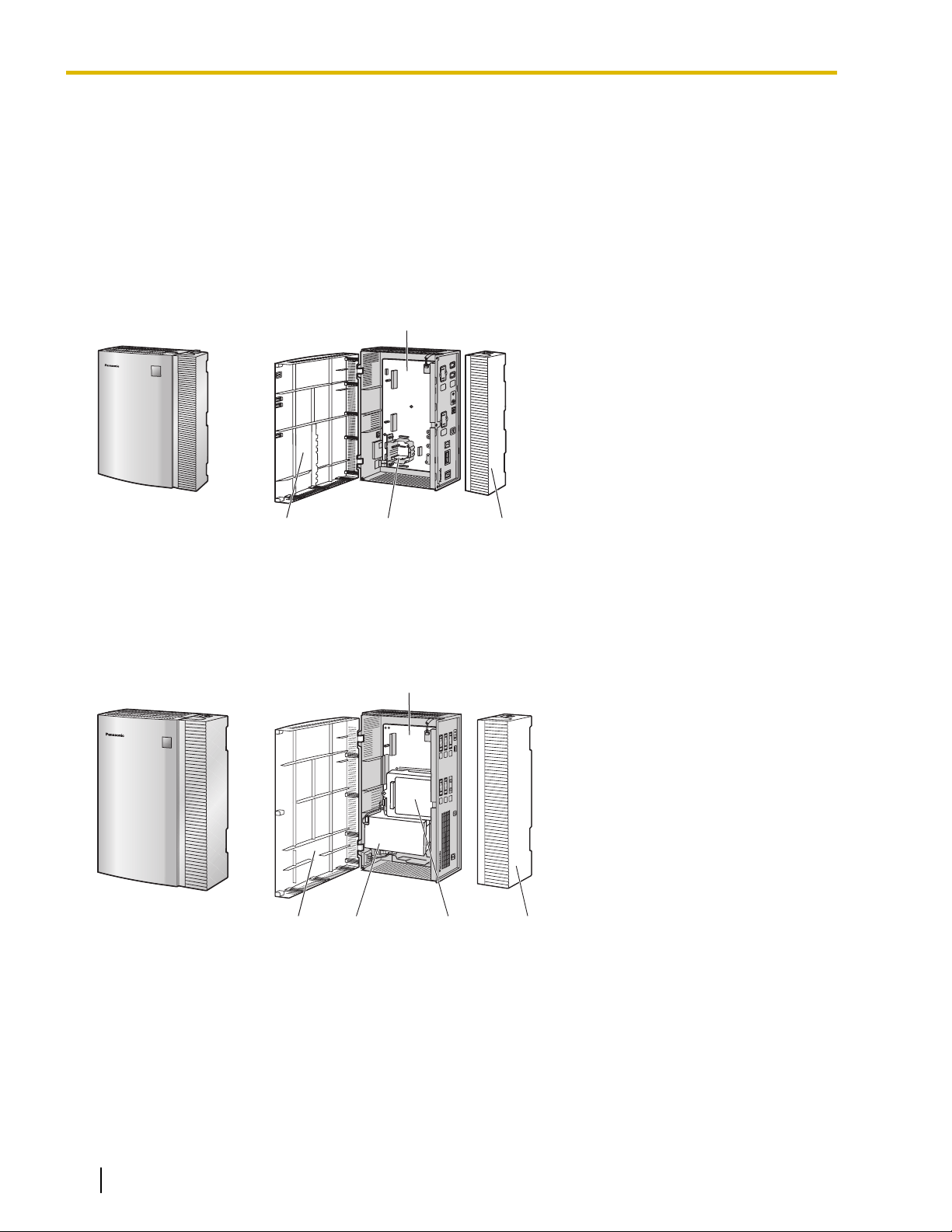
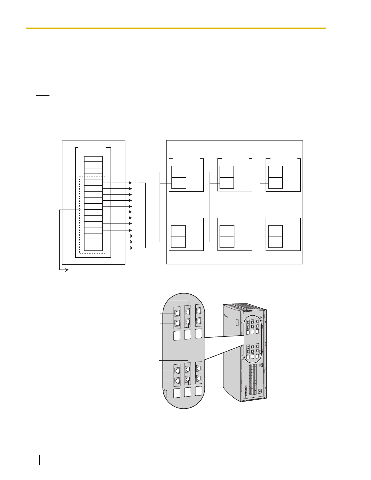
1.1.1 Main Unit
1.1 Basic System Construction
1.1.1 Main Unit
The KX-TVA50 is equipped with 2 jacks in its initial configuration, and its flash memory card provides 4 hours
of recording capacity. The KX-TVA200 is equipped with 2 jacks in its initial configuration, and its hard disk drive
provides 1000 hours of recording capacity. Both systems can be expanded by adding optional service cards.
KX-TVA50
1. Main Board
2. Front Cover
3. Factory-installed Flash Memory Card
4. Cable Cover
KX-TVA200
1. Main Board
2. Front Cover
3. 3.5" Hard Disk Drive
4. Factory-installed Port Card
5. Cable Cover
18 Installation Manual Document Version 3.0 2010/06
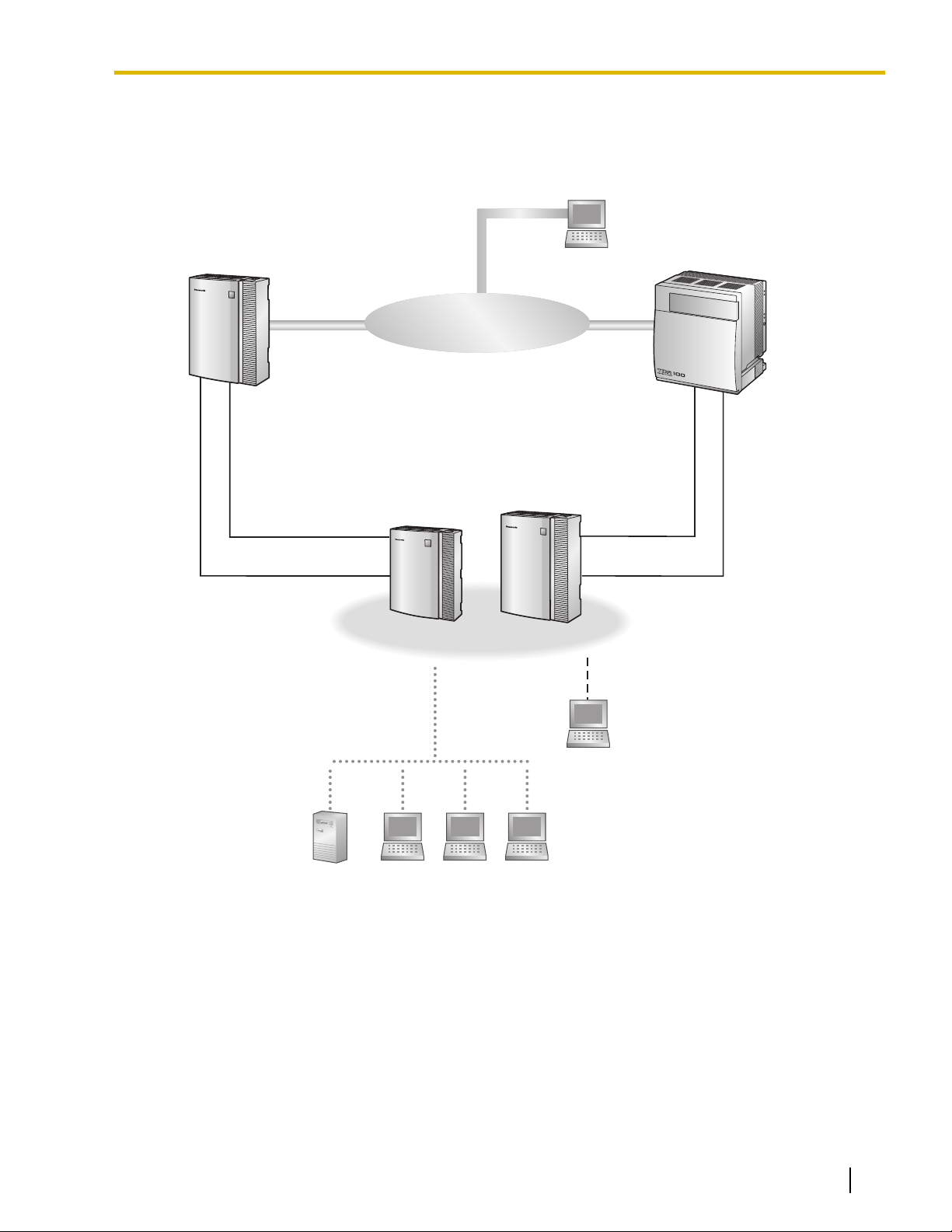
1.1.2 System Connection Diagram
Remote PC
Voice Processing System
PC PC PC
PC
USBLAN
PBXPBX
Server PC
Internal
Modem
Internal
Modem
DPT/APT/Inband
Interface
DPT
Interface
KX-TVA50
KX-TVA50
KX-TVA200
KX-TVA200
KX-TVA50
KX-TVA200
Telephone Company Lines
1.1.2 System Connection Diagram
Document Version 3.0 2010/06 Installation Manual 19
1.1.5 Installer Equipment and Software Requirements
1.1.3 Options
Optional Cards—KX-TVA50
Model Model Name Maximum Quantity
KX-TVA502 2-Port Hybrid Expansion Card 2
KX-TVA503 2-Port Digital Expansion Card 2
KX-TVA524 Memory Expansion Card 1
KX-TVA594 LAN Interface Card 1
KX-TVA296 Modem Card 1
Optional Cards—KX-TVA200
Model
KX-TVA204 4-Port Digital Expansion Card 5
KX-TVA296 Modem Card 1
Model Name Maximum Quantity
1.1.4 Initial Configuration and Expansion Capabilities
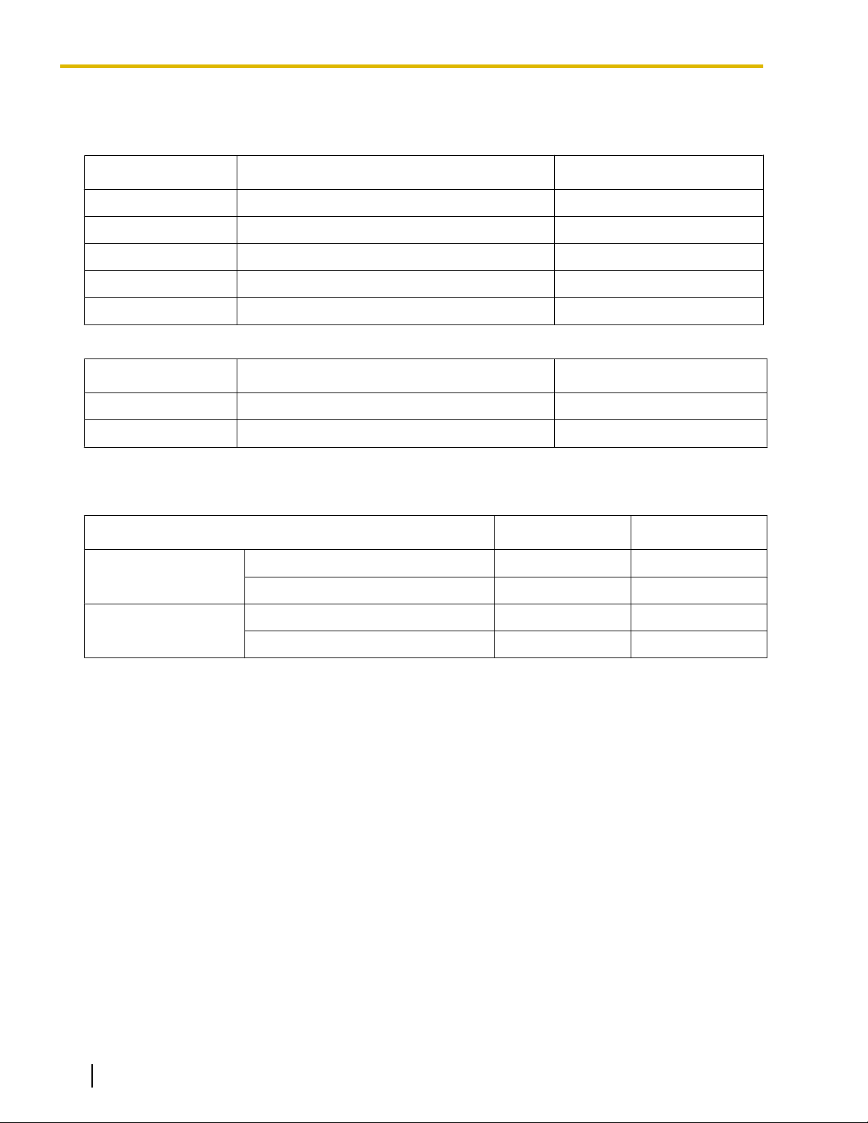
Specification
No. of Ports Initial Configuration 2 4
Maximum 6 24
Recording Time Initial Configuration 4 hours 1000 hours
Maximum 8 hours —
KX-TVA50 KX-TVA200
1.1.5 Installer Equipment and Software Requirements
The installer must use a PC and the KX-TVA Maintenance Console software to configure and customize the
VPS. The PC can be connected via the built-in USB port of the VPS, or can access the VPS over a local
network via the built-in LAN port (KX-TVA200) or an optional KX-TVA594 LAN Interface Card (KX-TVA50).
Off-site programming is also possible provided an optional KX-TVA296 Modem Card is installed in the VPS.
For more information, see Section 3 Installing KX-TVA Maintenance Console.
20 Installation Manual Document Version 3.0 2010/06
1.1.6 Recommendations for System Configuration
1.1.6 Recommendations for System Configuration
In order for the VPS to handle calls smoothly, generally there should be 1 VPS port for every 6 trunks (CO
lines) connected to the PBX. If Automated Attendant (AA) service is used, allotting 1 VPS port for every 4
trunks (CO lines) should be sufficient. If the PBX and VPS have heavy traffic and callers cannot reach the VPS
because of congestion, more VPS ports should be added.
Recommendations are outlined in the following charts.
KX-TVA50
PBX
No. of Trunks
(CO Lines)
(CO Lines) When Using
1–6 1–4 1
7–12 5–8 2
13–18 9–12 3
19–24 13–16 4
25–30 17–20 5
31–36 21–24 6
*1
The factory-installed jacks should be sufficient.
KX-TVA200
PBX
No. of Trunks
(CO Lines)
1–6 1–4 1
(CO Lines) When
Using AA Service
No. of Trunks
AA Service
No. of Trunks
No. of Ports
No. of Ports
KX-TVA50
KX-TVA200
No. of Optional Port
No. of Optional Port
Cards
*1
0
1
2
Cards
7–12 5–8 2
*1
0
13–18 9–12 3
19–24 13–16 4
25–30 17–20 5
31–36 21–24 6
1
37–42 25–28 7
43–48 29–32 8
49–54 33–36 9
55–60 37–40 10
2
61–66 41–44 11
67–72 45–48 12
Document Version 3.0 2010/06 Installation Manual 21
1.1.6 Recommendations for System Configuration
PBX KX-TVA200
No. of Trunks
(CO Lines)
(CO Lines) When
Using AA Service
73–78 49–52 13
79–84 53–56 14
85–90 57–60 15
91–96 61–64 16
97–102 65–68 17
103–108 69–72 18
109–114 73–76 19
115–120 77–80 20
121–126 81–84 21
127–132 85–88 22
133–138 89–92 23
139–144 93–96 24
*1
The factory-installed jacks should be sufficient.
No. of Trunks
No. of Ports
No. of Optional Port
Cards
3
4
5
22 Installation Manual Document Version 3.0 2010/06

1.1.7 Compatible PBXs
The VPS can be integrated with the following PBXs using the integration types listed below.
KX-TVA50
1.1.7 Compatible PBXs
PBX Model
KX-TDE Series DPT Integration
KX-TDA Series DPT Integration
KX-TAW Series DPT Integration
KX-TA1232 DPT Integration
KX-TA824 APT Integration
KX-TA624 APT Integration
KX-TD1232 DPT Integration
KX-TD816 DPT Integration
KX-TD500 DPT Integration
KX-TD308 DPT Integration
Third-party Manufacturer Inband Integration or No
Recommended Integration
Type
Integration
KX-TVA200
PBX Model
Recommended Integration
Type
Minimum Software Version for
Recommended Integration Type
1.0
1.0
1.0
Y831AA10621A
1.0.44
Y581A
P231U91227A
P301O91227A
P171AA010312A
P871F91227
—
Minimum Software Version for
Recommended Integration Type
KX-TDE Series DPT Integration
KX-TDA Series DPT Integration
KX-TAW Series DPT Integration
KX-TA1232 DPT Integration
KX-TD1232 DPT Integration
KX-TD816 DPT Integration
KX-TD500 DPT Integration
KX-TD308 DPT Integration
1.0
1.0
1.0
Y831AA10621A
P231U
P301O
P171AA010312A
P871F91227
Document Version 3.0 2010/06 Installation Manual 23

1.2.1 Overview
1.2 Voice Mail Integration
1.2.1 Overview
In order for the VPS to function, it must be integrated with the PBX it is connected to. The type of integration
that is used determines how voice (caller messages, VPS prompts, etc.) and data (extension status, button
presses, etc.) are sent between the VPS and the PBX.
DPT Integration
When the VPS and PBX use DPT Integration, voices and data are sent digitally. The most significant advantage
of DPT Integration is that the 2B+D communication provides 2 VPS ports for each port. DPT Integration requires
the proper software level in the PBX as well as 4-conductor connections for each jack. In order for the VPS to
function properly using DPT Integration, the PBX and VPS must be programmed to work together. For a list
of PBXs that are compatible with DPT integration, see 1.1.7 Compatible PBXs.
To use DPT Integration, the lowest numbered jack of the VPS must be connected to the lowest numbered jack
assigned as a voice mail port in the PBX. See the DPT connection example(s) for your VPS model in the
following sections:
1.2.2 Connection Examples—KX-TVA50
1.2.3 Connection Examples—KX-TVA200
Connect the other jacks to the VPS in the same order as they are found in Voice Mail Port Assignment in the
PBX.
APT Integration (KX-TVA50 only)
When the VPS and PBX use APT Integration, voices are sent using analog technology, and data is sent
digitally. APT Integration requires the proper software level in the PBX as well as 4-conductor connections for
each jack. In order for the VPS to function properly using APT Integration, the PBX and VPS must be
programmed to work together. For a list of PBXs that are compatible with APT integration, see 1.1.7 Compatible
PBXs.
Inband Integration (KX-TVA50 only)
When the VPS and PBX use Inband Integration, voices are sent using analog technology, and data is sent
using analog DTMF tones.
No Integration (KX-TVA50 only)
When the VPS and PBX use no integration, voices are sent using analog technology and data is sent to the
VPS through the use of standard audio signals, such as DTMF tones, busy signals, ringback tones, etc.
24 Installation Manual Document Version 3.0 2010/06
PBX (KX-TDA50)
Slot 1
Port 2
Port 1
Port 4
Port 3
Port 2
Port 1
KX-TVA50
Assigned as VM (DPT) ports
Jack 1
Jack 2
Factory- installed
Jacks
Slot 3
Port 6
Port 5
Jack 5
Jack 6
KX-TVA502
Slot 2
Port 4
Port 3
Jack 3
Jack 4
KX-TVA502
DLC4 Card
01
02
03
01
02
03
Jack 6
Jack 5
Jack 2
Jack 1
Jack 4
Jack 3
1.2.2 Connection Examples—KX-TVA50
1.2.2 Connection Examples—KX-TVA50
DPT Integration
When using DPT Integration, VPS jacks are connected to the digital extension ports of the PBX. Note that only
odd numbered VPS jacks (1, 3, and 5) can be used. Each of these VPS jacks provides 2 VPS ports and can
handle 1 call per port.
Note
• For DPT Integration, the lowest numbered jack of the VPS must be connected to the lowest numbered
port of the Voice Mail group assigned through PBX programming.
Connection Example (Factory-installed Jacks and KX-TVA502 ´ 2, DPT Integration
Mode)
Document Version 3.0 2010/06 Installation Manual 25

KX-TVA50
PBX (KX-TA824)
Assigned as VM1 APT ports
Jack 7
Jack 8
Port 2
Port 1
Jack 1
Jack 2
Factory- installed
Jacks
Slot 1
Port 4
Port 3
Jack 3
Jack 4
KX-TVA502
Slot 2
Jack 15
Jack 16
01
02
03
01
Jack 2
Jack 1
1.2.2 Connection Examples—KX-TVA50
APT Integration
When using APT Integration, VPS jacks are connected to the hybrid extension jacks of the PBX. Each VPS
jack provides 1 VPS port and can handle 1 call per port.
Note
• Jack 1 must be connected to the PBX.
Connection Example (Factory-installed Jacks and KX-TVA502 ´ 1, APT Integration
Mode)
Note
• A maximum of 4 VPS jacks can be connected to the PBX.
26 Installation Manual Document Version 3.0 2010/06
PBX (KX-TDA50)
Slot 1
Port 2
Port 1
Port 4
Port 5
Port 6
Port 7
Port 8
Port 3
Port 2
Port 1
KX-TVA50
Jack 1
Jack 2
Slot 3
Port 6
Port 5
Jack 5
Jack 6
KX-TVA502 KX-TVA502
Slot 2
Port 4
Port 3
Jack 3
Jack 4
KX-TVA502
SLC8 Card
01
02
03
01
02
03
Jack 6
Jack 5
Jack 2
Jack 1
Jack 4
Jack 3
1.2.2 Connection Examples—KX-TVA50
Inband/No Integration
When using Inband/No Integration, VPS jacks are connected to the SLT ports of the PBX. Each VPS jack
provides 1 VPS port and can handle 1 call per port.
Connection Example (Factory-installed Jacks and KX-TVA502 ´ 2, Inband/No Integration
Mode)
Document Version 3.0 2010/06 Installation Manual 27
PBX (KX-TDA100)
Slot 1
Port 4
Port 3
Port 2
Port 1
Port 4
Port 3
Port 2
Port 1
Port 8
Port 7
Port 6
Port 5
Port 12
Port 11
Port 10
Port 9
Port 16
Port 15
Port 14
Port 13
KX-TVA200
Assigned as VM (DPT) ports
Jack 1
Jack 2
KX-TVA204
Slot 3
Port 10
Port 11
Port 12
Port 9
Jack 5
Jack 6
KX-TVA204
Slot 5
Port 18
Port 17
Port 19
Port 20
Port 21
Port 22
Port 23
Port 24
Jack 10
Jack 9
KX-TVA204
Slot 6
Jack 12
Jack 11
KX-TVA204
Slot 4
Port 14
Port 13
Port 15
Port 16
Jack 7
Jack 8
KX-TVA204
Slot 2
Port 8
Port 7
Port 6
Port 5
Jack 3
Jack 4
KX-TVA204
DLC16 Card
To KX-TVA200
12
11
10
9
8
7
6
5
4
3
2
1
01
02
03
04
05
06
01
02
03
04
05
06
Jack
Jack 12
Jack 8
Jack 4
Jack 3
Jack 7
Jack 2
Jack 1
Jack 11
Jack 10
Jack 9
Jack 6
Jack 5
1.2.3 Connection Examples—KX-TVA200
1.2.3 Connection Examples—KX-TVA200
DPT Integration
The KX-TVA200 supports DPT Integration only, therefore it must be connected to the digital extension ports
of the PBX. Each VPS jack provides 2 VPS ports and can handle 1 call per port.
Note
• For DPT Integration, the lowest numbered jack of the VPS must be connected to the lowest numbered
port of the Voice Mail group assigned through PBX programming.
Connection Example (KX-TVA204 ´ 6, DPT Integration Mode)
28 Installation Manual Document Version 3.0 2010/06

1.3 Specifications
Hardware
Specification KX-TVA50 KX-TVA200
1.3 Specifications
Available Port Cards 2-Port Hybrid Expansion Card
(KX-TVA502)
2-Port Digital Expansion Card
(KX-TVA503)
Number of Port Card Slots 2 6
Data Ports USB (built-in)
LAN (optional)
Modem (optional)
Additional Hardware Mode Switch
Telephone Line
Connections
• APT/DPT Integration: 4-conductor
cable
• Inband/No Integration:
2-conductor cable
Message Recording Medium
Recording Capacity 4 h (expandable to 8 h)
Main CPU 32-bit microprocessor
Compression Rate 32 Kbps
Internal Modem Type V.90
Dialing Method DTMF
Flash Memory
*1
4-Port Digital Expansion Card
(KX-TVA204)
USB (built-in)
LAN (built-in)
Modem (optional)
4-conductor cable
Internal Hard Disk Drive (HDD)
1000 h
Flash Time 100 ms/300 ms/600 ms/900 ms
(programmable)
CPC Detection None/6.5 ms/150 ms/300 ms/450 ms/
600 ms (programmable)
Line Type
• Loop start minimum Loop Current:
20 mA
• Minimum Line Voltage: 7 V DC
–
–
–
• Minimum Ringing Voltage: 40 V
AC
Extension Numbering 2 to 8 digits (programmable)
Pause Length 100 ms to 9900 ms (programmable)
Message Waiting Lamp
*1
The recording capacity specification shown here for the KX-TVA50 applies to when one system prompt language is installed.
Recording capacity is reduced by about 1 hour for each additional system prompt language that is installed.
• APT/DPT Integration: Data Line of
APT/DPT Interface
• Inband Integration:
Programmable DTMF sequence
Data Line of DPT Interface
Document Version 3.0 2010/06 Installation Manual 29
1.3 Specifications
Software
Specification KX-TVA50 KX-TVA200
Custom Services Up to 100
Number of Messages Unlimited
Length of Personal
Greeting Message
Message Retention Time
Maximum Message Length
Maximum Combined Length of
Messages per Mailbox
No. of Mailboxes 62 Subscriber + 2 Manager 1022 Subscriber + 2 Manager
Reports Mailbox Information Report
Call Account Report (Group calls by
Port)
Call Account Report (Group calls by
Mailbox)
Port Usage Report
Memory Card Usage Report
Mailbox Usage Report
Fax Call Report
Call Handling Statistics Report
Custom Service Report
Message Status Report
Subscriber Setup Report
Security Information Report
Hourly Statistics Report
E-mail Report
1 to 120 min., unlimited
(programmable)
Up to 360 s (programmable)
1 to 30 days, unlimited (programmable)
1 to 60 min., unlimited (programmable)
1 to 600 min., unlimited
(programmable)
Mailbox Information Report
Call Account Report (Group calls by
Port)
Call Account Report (Group calls by
Mailbox)
Port Usage Report
HDD Usage Report
Mailbox Usage Report
Fax Call Report
Call Handling Statistics Report
Custom Service Report
Message Status Report
Subscriber Setup Report
Security Information Report
Hourly Statistics Report
E-mail Report
Environment
Specification
Environmental Requirements
Power Source 100 V AC to 240 V AC, 0.25 A,50 Hz/
DC Input
Dimensions (W ´ H ´ D) 249 mm (W) ´ 316 mm (H)
(9-13/16 in. ´ 12-7/16 in.
30 Installation Manual Document Version 3.0 2010/06
KX-TVA50 KX-TVA200
5 °C to 40 °C
(41 °F to 104 °F)
60 Hz
9 V, 0.75 A (6.75 W)
´ 73 mm (D)
´ 2-7/8 in.)
Refer to "Environmental
Requirements", 2.1 Before
Installation
100 V AC to 240 V AC, 1.5 A, 50 Hz/
60 Hz (Panasonic AC adaptor,
PSLP1244) or 110 V AC to 240 V
AC, 1.35 A, 50 Hz/60 Hz (Panasonic
AC adaptor, PSLP1434)
40 V, 1.38 A (55.2 W)
275 mm (W) ´ 376 mm (H) ´ 117 mm
(10-13/16 in. ´ 14-13/16 in. ´ 4-5/8
(D)
in.)
 Loading...