

Panasonic EYFGB2N, EYFGB3N, EYFGA1N, EYFGA3N, EYFGA2NR Owner's Manual
...
Operating Instructions
Instructions d’utilisation
Manual de instrucciones
Cordless Screwdriver
Tournevis sans l
Destornillador inalámbrico
Model No: EYFGA1N
EYFGA2N
EYFGA3N
IMPORTANT
This manual contains safety information. Read manual completely before rst using this product and save this
manual for future use.
IMPORTANT
Ce manuel contient des informations de sécurité. Veuillez lire l'intégralité du manuel avant la première utilisation de
ce produit et conservez ce manuel pour les utilisations futures.
IMPORTANTE
Este manual tiene información de seguridad. Lea todo el manual antes de usar este producto por primera vez y
guarde el manual para poderlo consultar en el futuro.
EYFA31
A
B
C D
Index/Index/Indice
English: Page 4
Français: Page 18
Español: Página 34
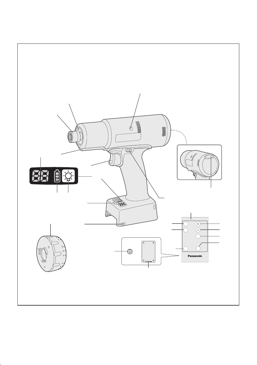
FUNCTIONAL DESCRIPTION
DESCRIPTION DES FONCTIONS
DESCRIPCIÓN FUNCIONAL
(B)
(A)
(K)
(M)
(L)
(H)
(C)
(I)(J)
(G)
(E)
(N)
(X)
(F)
(U)
(T)
(W)
(S)
(V)
Remote control, clutch setting handle and battery are not included.
La télécommande, la poignée de réglage de l'embrayage et la batterie ne sont pas incluses.
El control remoto, la empuñadura de ajuste de embrague y la batería no están incluidos.
-
2 -
(D)
(O)
(P)
(Q)
(R)

6.35 mm (1/4") hex quick connect chuck
Mandrin de connexion rapide hexagonal 6,35 mm
(A)
Mandril hexagonal de conexión rápida de 6,35 mm
Hole for tool hanger
Trou pour dispositif de suspension de l'outil
(C)
Oricio para el colgador de la herramienta
Forward/Reverse lever
Levier d’inversion marche avant/marche arrière
(E)
Palanca de avance/marcha atrás
Remote control receiver
Récepteur de la télécommande
(G)
Receptor de control remoto
LED light on/off button
Bouton Marche/Arrêt de la lumière DEL
(I)
Botón ENCENDIDO/APAGADO de luz LED
Display
Afchage
(K)
Visor
LED light
Lumière DEL
(M)
Luz LED
+ button
Bouton +
(O)
Botón +
OK button
Bouton OK
(Q)
Botón OK
C button
Bouton C
(S)
Botón C
A button
Bouton A
(U)
Botón A
Battery
Batterie
(W)
Batería
Clutch shutter
Volet d'embrayage
(B)
Cierre del embrague
Tightening conrmation lamp
Témoin de conrmation de serrage
(D)
Lámpara de conrmación de apriete
Alignment mark
Marques d’alignement
(F)
Marcas de alineación
Control panel
Panneau de commande
(H)
Panel de control
Battery indication lamp
Témoin indicateur de la batterie
(J)
Lámpara de indicadora de la batería
Variable speed control trigger
Gâchette de commande de vitesse
(L)
Disparador del control de velocidad variable
Remote control
Télécommande
(N)
Control remoto
− button
Bouton −
(P)
Botón −
D button
Bouton D
(R)
Botón D
B button
Bouton B
(T)
Botón B
Holder
Support
(V)
Retenedor
Clutch setting handle
Poignée de réglage de l'embrayage
(X)
Empuñadura de ajuste de embrague
-
3 -

I
.
GENERAL SAFETY
RULES
WARNING! Read all instructions
Failure to follow all instructions listed
below may result in electric shock, fire
and/or serious injury. The term “power
tool” in all of the warnings listed below
refers to your mains operated (corded)
powe r tool and battery opera ted
(cordless) power tool.
SAVE THESE INSTRUCTIONS
Work Area Safety
1) Keep work area clean and well lit.
Cluttered or dark areas invite accidents.
2)
Do not operate power tools in explosive
atmospheres, such as in the presence
of flammable liquids, gases or dust.
Power tools create sparks which may
ignite the dust or fumes.
3)
Keep children and bystanders away
while operating a power tool.
Distractions can cause you to lose control.
Electrical Safety
1) Power tool plugs must match the
outlet. Never modify the plug in any
way. Do not use any adapter plugs
with earthed (grounded) power tools.
Unmodified plugs and matching outlets
will reduce risk of electric shock.
2)
Avoid body contact with earthed or
grounded surfaces such as pipes,
radiators, ranges and refrigerators.
There is an increased risk of electric shock
if your body is earthed or grounded.
3) Do not expose power tools to rain or
wet conditions.
Water entering a power tool will increase
the risk of electric shock.
4)
Do not abuse the cord. Never use
the cord for carrying, pulling or
unplugging the power tool. Keep
cord away from heat, oil, sharp edges
or moving parts.
Damaged or entangled cords increase
the risk of electric shock.
5)
When operating a power tool outdoors,
use an extension cord suitable for
outdoor use.
Use of a cord suitable for outdoor use
reduces the risk of electric shock.
Personal Safety
1)
Stay alert, watch what you are doing
and use common sense when operating
a power tool. Do not use a power tool
while you are tired or under the influence
of drugs, alcohol or medication.
A moment of inattention while operating
power tools may result in personal injury.
2)
Use safety equipment. Always wear
eye protection.
Safety equipment such as dust mask,
non-skid safety shoes, hard hat, or
hearing protection used for appropriate
conditions will reduce personal injuries.
3)
Avoid accidental starting. Ensure the
switch is in the off position before
plugging in.
Carrying power tools with your finger on
the switch or plugging in the power tools
that have the switch on invites accidents.
4)
Remove any adjusting key or wrench
before turning the power tool on.
A wrench or a key left attached to a
rotating part of the power tool may result
in personal injury.
5)
Do not over reach. Keep prope r
footing and balance at all times.
This enables better control of the power
tool in unexpected situations.
6)
Dress properly. Do not wear loose
clothing or jewellery. Keep your
hair, clothing and gloves away from
moving parts.
Loose clothes, jewellery or long hair can
be caught in moving parts.
7)
If devices are provided for t he
connection of dust extraction and
collection facilities, ensure these are
connected and properly used.
Use of these devices can reduce dust
related hazards.
Power Tool Use and Care
1)
Do not force the power tool. Use the
correct power tool for your application.
The correct power tool will do the job
better and safer at the rate for which it
was designed.
2)
Do not use the power tool if the
switch does not turn it on and off.
Any power tool that cannot be controlled
with the switch is dangerous and must
be repaired.
3)
Disconnect the plug from the power
source and/or the battery pack from
-
4 -

the power tool before making any
adjustments, changing accessories,
or storing power tools.
Such preventive safety measures
reduce the risk of starting the power tool
accidentally.
4)
Store idle power tools out of the reach
of children and do not allow persons
unfamiliar with the power tool or these
instructions to operate the power tool.
Power tools are dangerous in the hands
of untrained users.
5)
Maintain power tools. Check for
misalignment or binding of moving
parts, breakage of parts and any other
condition that may affect the power
tools operation. If damaged, have the
power tool repaired before use.
Many accidents are caused by poorly
maintained power tools.
6)
Keep cutting tools sharp and clean.
Properly maintained cutting tools with
sharp cutting edges are less likely to
bind and are easier to control.
7)
Use the power tool, accessories
and tool bits etc. in accordance with
these instructions and in the manner
intended for the particular type of
power tool, taking into account the
working conditions and the work to
be performed.
Use of the power tool for operations
different from those intended could
result in a hazardous situation.
Battery Tool Use and Care
1) Ensure the switch is in the off position
before inserting battery pack.
Inserting battery pack into power tools
that have the switch on invites accidents.
2)
Recharge o nly with the charger
specified by the manufacturer.
A charger that is suitable for one type
of battery pack may create a risk of fire
when used with another battery pack.
3)
Use power tools only with specifically
designated battery packs.
Use of any other battery packs may
create a risk of injury and fire.
4)
When battery pack is not in use, keep it
away from other metal objects like paper
clips, coins, keys, nails, screws, or other
small metal objects that can make a
connection from one terminal to another.
Shorting the battery terminals together
may cause burns, or a fire.
5)
Under abusive conditions, liquid may
be ejected from battery; avoid contact.
If contact accidentally occurs, flush
with water. If liquid contacts eyes,
additionally seek medical help.
Liquid ejected from the battery may
cause irritation or burns.
Service
1) Have your power tool serviced by a
qualified repair person using only
identical replacement parts.
This will ensure that the safety of power
tool is maintained.
II
. INTENDED USE
This tool is a Cordless Screwdriver and can
be used to tighten bolts, nuts, and screws with
torque control.
III
.
ADDITIONAL
SAFETY RULES
1
) Wear ear protectors when using the
tool for extended periods.
2) Be aware that this tool is always in an
operating condition, since it does not have
to be plugged into an electrical outlet.
3) Hold power tools by insulated gripping
surfaces when performing an operation
where the cutting tool may contact hidden wiring or its own cord.
Contact with a “live” wire will make exposed
metal parts of the tool “live” and shock the
operator.
4) Do NOT operate the Forward/Reverse
lever when the main switch is on. The battery will discharge rapidly and damage to
the unit may occur.
5) During charging, the charger may become
slightly warm. This is normal.
Do NOT charge the battery for a long period.
6) When storing or carrying the tool, set the
Forward/Reverse lever to the center posi-
tion (switch lock).
7) Do not strain the tool by holding the speed
control trigger halfway (speed control
mode) so that the motor stops.
-
5 -
Symbol Meaning
V
n
0
Volts
Direct current
No load speed
CAUTION:
• If the collar does not return to its origi
nal position or the bit comes out when
pulled on, the bit has not been properly
attached. Make sure the bit is properly
attached before use.
9 mm – 13 mm
(23/64" – 33/64")
6.35 mm
(1/4")
-
-1
… min
Ah
IV
. ASSEMBLY
Revolutions or
reciprocations per minutes
Electrical capacity of battery
pack
To reduce the risk of
injury, user must read and
understand instruction
manual.
Do not incinerate or heat
battery pack. Do not charge
or use under conditions of
high temperature. Do not ex-
pose to high temperatures.
Do not disassemble or
modify.
Do not expose to rain or
water.
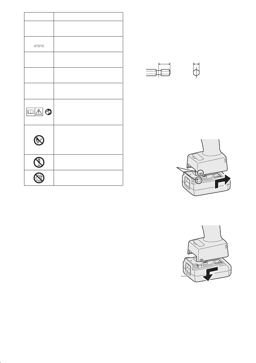
Attaching or Removing Bit
NOTE:
•
When attaching or removing a bit, disconnect battery pack from tool or place the
switch in the center position (switch lock).
1. Hold the collar of quick connect chuck and
pull it out from the tool.
2. Insert the bit into the chuck. Release the
collar.
3. The collar will return to its original position
when it is released.
Pull the bit to make sure it does not come out.
4.
5. To remove the bit, pull out the collar in the
same way.
Attaching or Removing Battery Pack
1. To connect the battery pack:
Align the highlighted marker points and
attach battery pack.
Slide the battery pack until it locks into
•
position.
Alignment
marks
2. To remove the battery pack:
Push down the button and slide the battery
pack forward.
Button
-
6 -
V.
Approx. 50 cm
Vertically
A
p
p
r
o
x
.
6
0
°
A
p
p
r
o
x
.
6
0
°
Forward Reverse
Switch lock
OPERATION
Before Using the Remote
Control (Available as an
optional accessory)
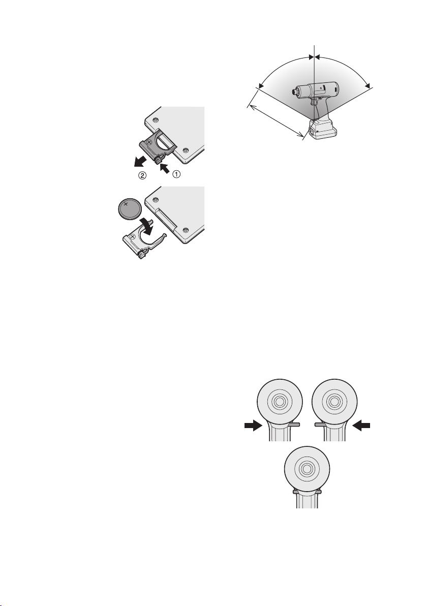
Insert the battery
1. Pull out the battery holder.
1 Push in on the fas-
tener as indicated by
the arrow.
2 Pull out the holder.
2. Insert the battery and
push the holder
back in.
NOTE:
• If the tool does not respond to the wire
less remote control even when the remote
control is operated close to the tool, the
battery (CR2025) is dead. Replace it with
a new battery.
• The included battery is provided for sample
use and may not last as long as commercially available batteries.
Wireless remote control range
The remote control should be operated within
approximately 50 cm and approximately 60°
vertically and horizontally of the perpendicular
relative to the infrared receiver on the tool.
• Under the following circumstances, you may
not be able to operate the tool, even within
this range.
• If there is an object between the remote
control’s transmitter and the tool’s receiver.
• When used outdoors or in other environ
ments where the remote control receiver is
-
exposed to a strong light source, or when
the remote control transmitter or receiver is
dirty, the tool fails to respond, even when the
remote control is used within the operating
range.
[Main Body]
Switch and Forward/Reverse
Lever Operation
-
-
7 -
CAUTION:
To prevent damage, do not operate
Forward/Reverse lever until the bit comes
to a complete stop.
Forward Rotation Switch
Operation
1. Push the lever for forward rotation.
2. Depress the trigger switch slightly to start
the tool slowly.
3. The speed increases with the amount of
depression of the trigger for efficient tightening of screws. The brake operates and
the bit stops immediately when the trigger
is released.
4. After use, set the lever to its center posi
tion (switch lock).
NOTE
• The tightening confirmation lamp will
not turn on under the following conditions:
• During reverse rotation operation
• The lamp turns off when the tool is in
operation.
Control Panel
-
Reverse Rotation Switch
Operation
1.
Push the lever for reverse rotation. Check
direction of rotation before use.
Depress the trigger switch slightly to start the
2.
tool slowly.
3. After use, set the lever to its center position (switch lock).
CAUTION:
• To eliminate excessive temperature
increase of the tool surface, do not
operate the tool continuously using two
or more battery packs. Tool needs cool
off time before switching to another
pack.
Tightening confirmation lamp
• The tightening confirmation lamp can be
used to check whether tightening has been
completed properly.
Tool status Lamp display
Tightening complete
(Normal clutch operation)
• Tightening not complete
• Tightening complete
without fullling the set
function conditions
The automatic poweroff function has been
activated.
Green
(For approx. 2
seconds)
Red
(For approx. 2
seconds)
Red
(For approx. 5
minutes)
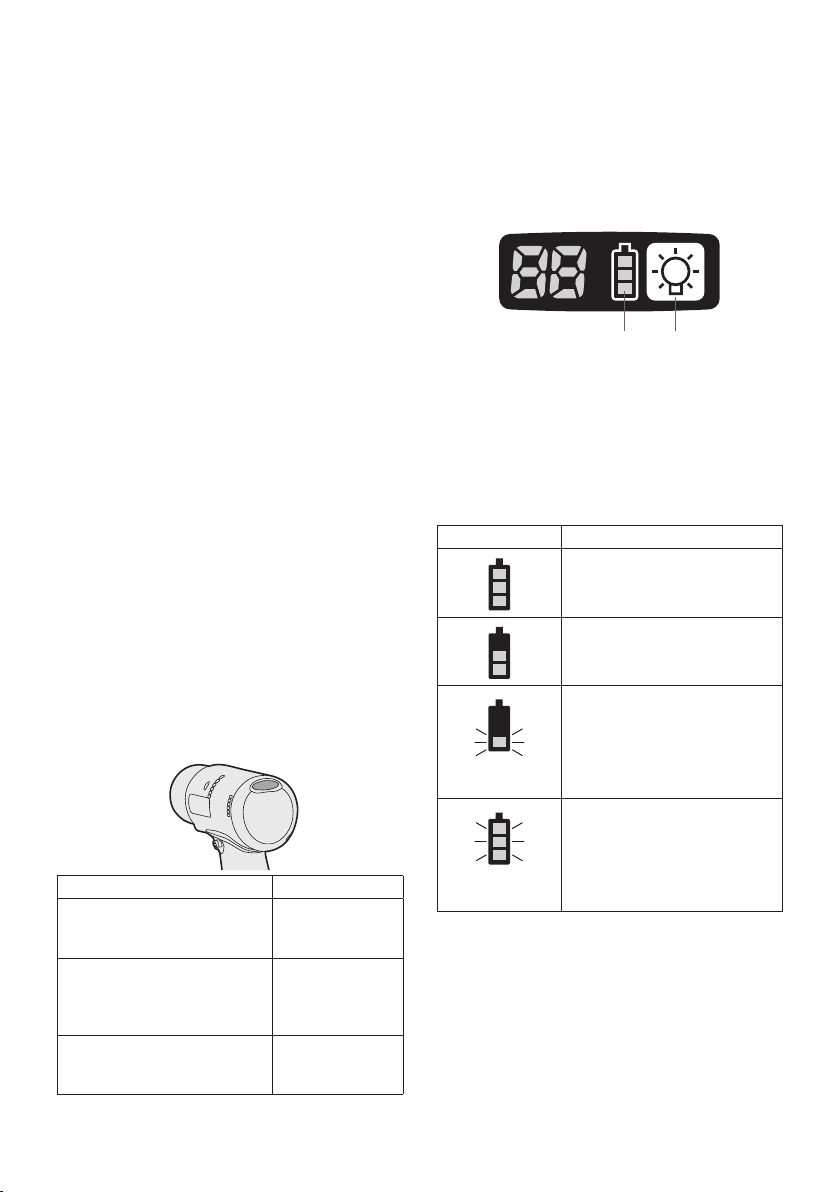
the
(1) (2)
(1) The battery indication lamp
• Use the battery indication lamp to check
how much power is left in the battery.
• Battery life varies slightly with ambient tem-
perature and battery characteristics. The
lamp is designed to provide a rough indication of remaining battery life.
Indicator Battery status
Fully charged
Approx. 40% or less
remaining
Flashing
Approx. 20% or less
remaining (indicates need
to recharge battery)
Flashing
Flashing
The battery pack will need
to be charged soon.
No charge
The battery pack needs to
be charged.
(The tool’s automatic
power-off function will
activate at this stage.)
Automatic power-off function
• The automatic power-off function is designed
to prevent a loss of tightening torque due to
reduced battery voltage. Once it has been
activated, the tool will not operate until the
battery pack has been charged (or replaced
with a fresh unit), even if the trigger is
depressed.
-
8 -
NOTE:
• All 3 bars on the battery indication lamp
will flash when the automatic power-off
function is activated.
• When the battery indication lamp begins
flashing, the battery pack should be
charged (or replaced with a fresh unit)
immediately.
• Be sure to fully charge the battery pack
in question after activation of the auto-
matic power-off function. Failure to do
so may prevent the automatic power-off
function from being properly deactivated.
• The tool may power off automatically
under heavy work loads.
However the tool will be operational
again after the battery is removed and
reinstalled. The battery must have a
sufficient charge to re-enable the tool.
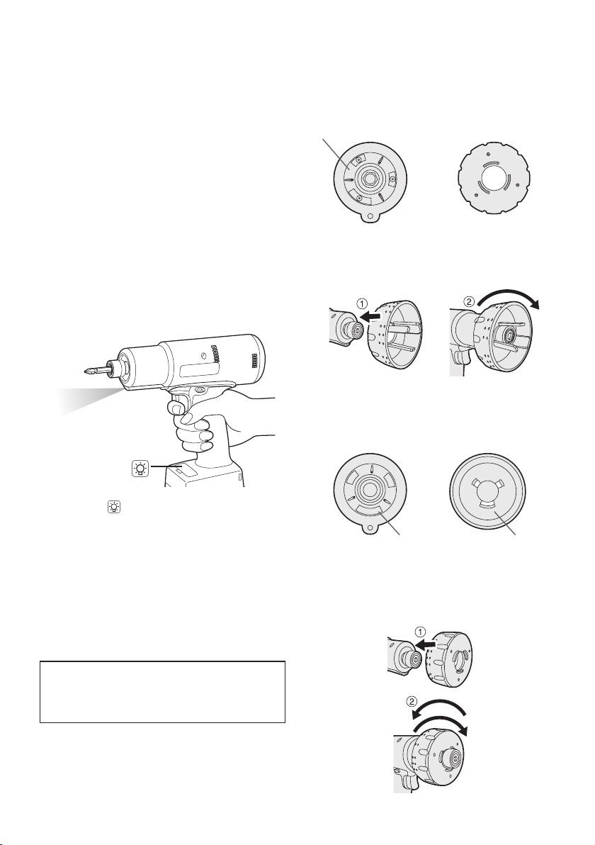
(2) LED light
Tightening Torque Setting
1. Open the shutter with the clutch setting
handle.
Front view of the
main unit
Shutter (closed)
Engage the ribs on the main unit with the
ribs on the clutch setting handle (on the
short side) and turn clockwise.
2. Insert the 3 ribs on clutch setting handle
(on the long side) into the shutter holes.
Make sure to insert the wider rib into big
ger hole.
Clutch setting handle
(short side view)
-
Pressing the button toggles the LED light on
and off.
The light consumes very little power and will
not significantly affect battery run time.
CAUTION:
•
The built-in LED light is designed to illuminate the small work area temporarily.
•
Do not use it as a substitute for a regular
flashlight, since it does not have
enough brightness
This tool has the built-in LED light.
Caution: DO NOT STARE INTO BEAM.
Use of controls or adjustments or performance
of procedures other than those specied herein
may result in hazardous radiation exposure.
NOTE:
• LED light can be linked to trigger switch
operation by setting with a remote control. (See page 13.)
.
-
Bigger hole Wider rib
To set clutch torque, turn the clutch setting
handle clockwise or counterclockwise.
Clutch stage can be set from 1 to 60 stage.
(two full turns)
Decrease torque
Increase torque
9 -
Example-clutch
0
2
4
6
8
10
12
(53.1)
(106.2)
(in·lbs)
1 10 3020 40 50 60
N
m
EYFGA3
EYFGA2
EYFGA1
setting #40
Example-clutch
setting #20
3. Close the shutter with the clutch setting
handle by turning counterclockwise.
NOTE:
• Be sure to close the shutter to prevent
dust.
Tightening torque chart (reference
values)
This data consists of reference values measured
under the conditions described below. During
actual work, values will vary based on operating
conditions (lock bolt, target substrate, method
of securing the bolt in place, etc.).
Measurement conditions
As dened by Panasonic
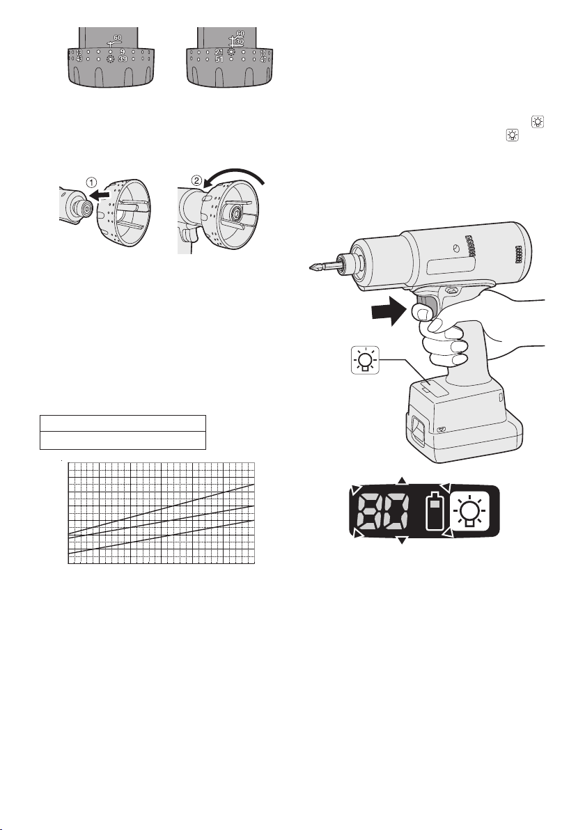
Configuring Tool Settings
RPM adjustment setting
1. Turn off the control panel.
• If the control panel is on, remove and
then reinsert the battery pack.
2. Depress the switch while pushing the
button and then release both the button and the switch.
• After the LED light and tightening con
firmation lamp have illuminated and the
buzzer has rung, the control panel will
flash and change to configuration mode.
-
Torque setting level
CAUTION:
• Always check the tool’s tightening
torque before use. Improper tool opera-
tion may result in excessive or inadequate tightening.
• Always operate the tool with the switch
fully depressed.
The torque accuracy may not be stable if
•
the switch is not sufficiently depressed.
•
Use figures from the tightening torque
chart to guide your selection of torque
clutch setting. (See the tightening torque
chart)
-
10 -
NOTE:
• Tools ship from the factory set to the
following mode.
EYFGA1: 80
EYFGA2: 75
EYFGA3: 45
• The control panel will turn off if the tool
is not operated for a period of 5 min-
utes.
EYFA31
A
B
C D
17…77
158079 1678
RPM GA1 GA2 GA3
80 800
75 750
Setting not
available
OK button
Display
Battery indication lamp
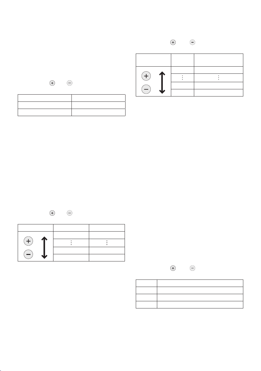
3. Press the and buttons to select the
clutch setting that is appropriate for the
work being performed.
As the button
is pressed
As the button
is pressed
45 450
15 150
4. Press the OK button to accept the select
ed speed adjustment setting.
• The control panel will stop flashing and
light up.
CAUTION:
• You must press the OK button in order
for the selected setting to take effect.
• Be sure to verify the new value after
changing the setting. (See page 13.)
Setting
available
Auto downshift function
• By having the tool operate at high speed
at the start of the tightening process then
shifting to low speed operation just before
the ti ght ener be comes f lus h the auto
downshift function increases tightening
speed while maintaining accuracy. When
Auto Downshift is enabled it downshifts
to a low speed of 300 RPM at the time
programmed with the remote control.
1. Set the tool to setting configuration mode.
(See page 10.)
2. Press the D button twice.
• The auto downshift function setting value
will be displayed.
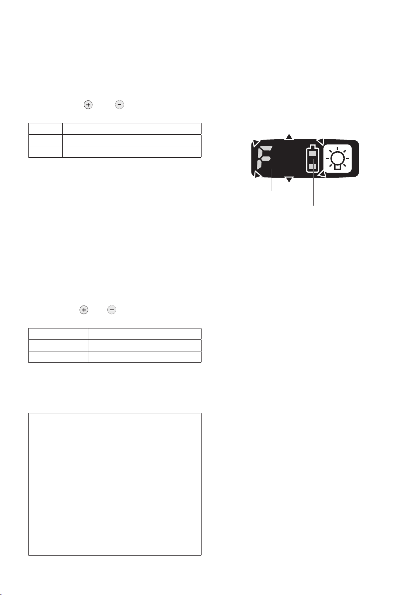
3. Press the
time as desired.
Operation Display Seconds
4. Press the OK button to accept the new
setting.
NOTE:
• The speed at the start of tightening
operation is set with the speed adjustment function.
and buttons to change the
30 3 seconds
1 0.1 seconds
0 OFF
-
11 -
-
Cross thread reduction function
• The tool runs in reverse approximately
360° before running forward to assist in
the alignment of the threads to help reduce
cross threads.
1. Set the tool to setting configuration mode.
(See page 10.)
2. Press the D button once.
• The cross thread reduction function set
ting value will be displayed.
3. Press the
setting to ON or OFF.
4. Press the OK button to accept the ON or
OFF setting.
and buttons to change the
Display Function
R0 OFF
R1 ON
Rundown error detecting function
• The rundown error detecting function causes
a red indicator to flash if work ends more
quickly than a set time, for example due
to retightening of a previously tightened
fastener or binding of the screw’s thread.
1. Set the tool to setting configuration mode.
(See page 10.)
2. Press the B button twice.
• The rundown error detecting function
setting value will be displayed.
3. Press the
time as desired.
Operation Display Seconds
4. Press the OK button to accept the new
setting.
• When the cross thread reduction func
tion is ON, the set time will be counted
after the tool operates in reverse for
approximately 360°.
and buttons to change the
30 3 seconds
1 0.1 seconds
0 OFF
Maintenance interval alarm function
• The maintenance interval alarm function
locks the tool so that it can no longer be
operated once a set number of tightening
op era tio ns ha s bee n per for med. This
function is conven ient when regularly
inspecting tool performance, for example.
1. Set the tool to setting configuration mode.
(See page 10.)
2. Press the C button twice.
• The setting value will be displayed.
3. Press the
desired value.
Operation Display
-
4. Press the OK button to accept the new
setting.
NOTE:
• When the remaining number of tighten
ing operations is 10,000 or less, the
display will alternate between “Setting”
and “1.” When the remaining number
of tightening operations reaches 0, the
value “0” will flash on the display.
To delay the inspection while retaining
the current tightening operation count
value, select a new setting value that is
greater than the current setting value.
To reset the count to 0, initialize the tool
(see page 13).
• The maximum tightening operation
count value is 990,000. Operations in
excess of 990,000 will not be counted.
and buttons to set the
Number of tightening
operations
99 990,000
1 10,000
0 OFF
Buzzer setting
• You can select from three buzzer modes.
1. Set the tool to setting configuration mode.
(See page 10.)
2. Press the A button twice.
• The current setting value will be dis
played.
3. Press the
desired value.
-
Display Function
b0 No buzzer
b1
b2 Buzzer accompanying red indicator
4. Press the OK button to accept the new
setting.
NOTE:
• The tool ships with the buzzer mode set
to b0 by default.
and buttons to set the
Buzzer accompanying green indicator
-
-
-
12 -
LED light setting
• You can select from two LED light modes.
1. Set the tool to setting configuration mode.
(See page 10.)
2. Press the B button once.
• The current setting value will be dis
played.
3. Press the
desired LED mode.
Display Function
L1 Linked to LED light button
L2 Linked to trigger switch operation
4. Press the OK button to accept the new
setting.
NOTE:
• The tool ships with the LED light mode
set to L1 by default.
and buttons to set the
Speed control function
• The speed (RPM) can be changed with the
amount of depression of the trigger.
1. Set the tool to setting configuration mode.
(See page 10.)
2. Press the B button three times.
• The setting value will be displayed.
3. Press the
setting to ON or OFF.
Operation Function
P0 Speed control ON
P1 Speed control OFF
Press the OK button to accept the new set-
4.
ting.
Initializing all settings
Factory settings
• Speed adjustment function
→ GA1: 80 GA2: 75 GA3: 45
• Auto downshift function → 0
• Cross thread reduction function → R0
• Rundown error detecting function → 0
• Maintenance interval alarm function
→ 0
• Radio signal range limitation function
→ C0
• Buzzer setting → b0
• LED light setting → L1
• Speed control setting → P0
and buttons to change the
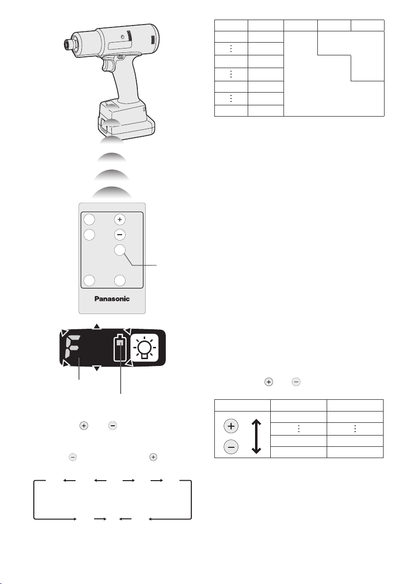
• This section explains how to revert all tool
settings to their default values at the time of
shipment from the factory.
• The error display will be turned off.
1. Set the tool to setting configuration mode.
-
(See page 10.)
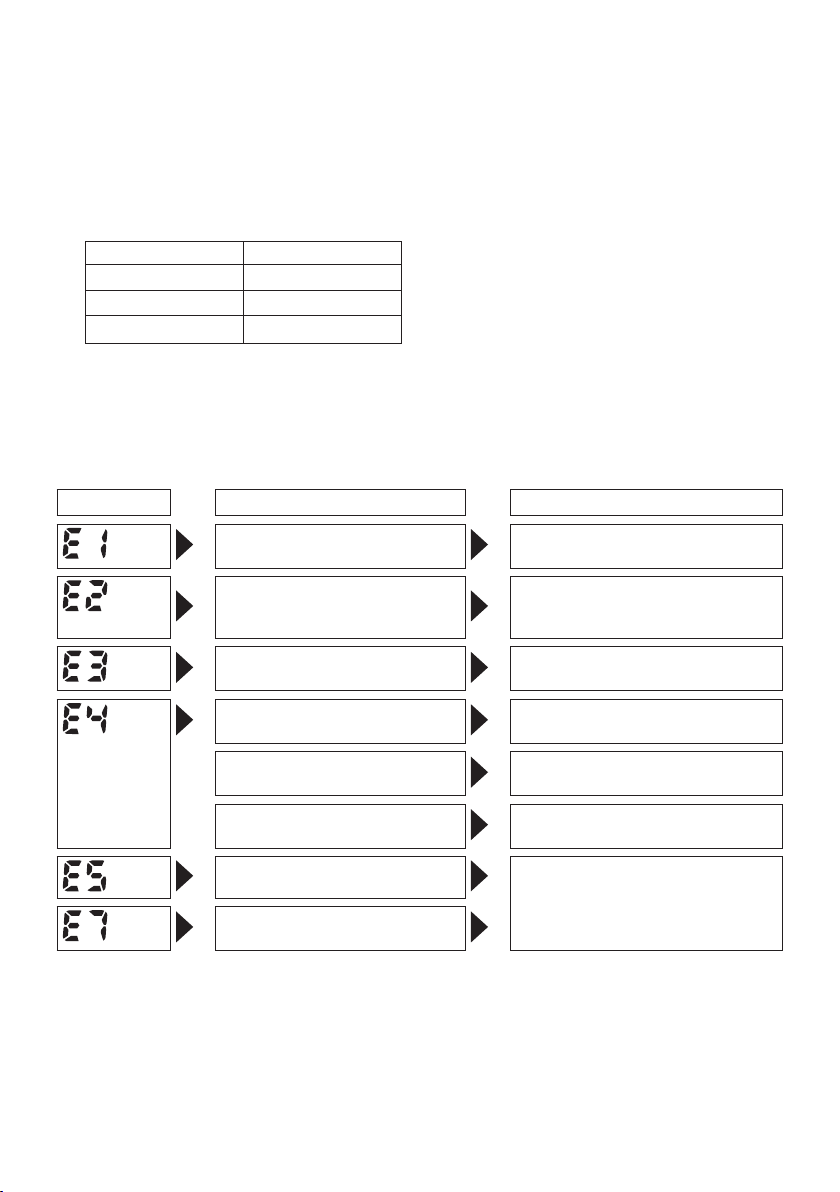
2. Press the C button.
• The control panel will begin flashing.
Display: The letter “F” ashes on and off.
Battery indication lamp: The upper and
lower bars of the battery ash on and off.
Display
Battery indication lamp
3. Press the OK button to accept the select-
ed setting.
• The control panel will stop flashing and
light up.
Checking tool settings
• When the tool stops, the current setting
value will be displayed for approximately 2
seconds.
• The setting status cannot be checked while
the tool panel is off. Depress the trigger
switch once to turn on the panel.
Checking the status of the speed
adjustment and buzzer settings
1. Press the A button.
• The RPM and buzzer setting values will
be displayed (in that order).
Example: If the RPM is set to 500 min
and the buzzer is set to sound at the
green indicator,
“50” → “b1”
Checking the status of the LED light
and rundown error detecting function and speed control function settings
1. Press the B button.
• The LED light and tightening time and
speed control setting will be displayed
(in that order).
Example: If the LED light mode is set to
L1 and the tightening time is set to 20
and speed control is set to ON,
“L1” → “20” → P0
-1
-
13 -
Checking the tool circuits and the
status of the cross thread reduction function and auto downshift
function settings
1. Press the D button.
• The tool circuits and cross thread reduc
tion function and auto downshift function
settings will be displayed (in that order).
Example: “H3” → “R1” → “10”
Display Tool circuit
H1 EYFGA1
H2 EYFGA2
H3 EYFGA3
-
NOTE:
• When other tools are in the area which
are not set, they may accidentally
receive a signal when setting the tool
by remote control.
Set the tool in another room if possible
or keep a fair distance to avoid this situation.
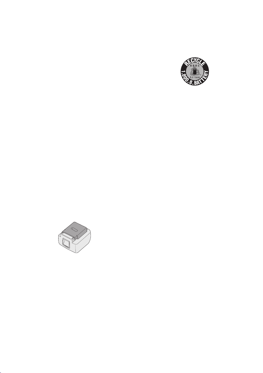
Error Display
In the event of a tool or battery pack malfunction, the control panel will display an error message.
Please check the tool or battery pack as described in the following chart before having them
serviced.
Display Likely cause Corrective action
Setting error Re-initialize the tool using the
The battery pack is too hot. Stop work and allow the battery
The tool is too hot to operate. Stop work and allow the tool to
The contacts that connect the
battery pack and tool are dirty.
The battery pack has not been
properly inserted into the tool.
The pins on either the tool or
battery pack have worn down.
Motor failure, etc. Stop using the tool immediately.
Tool circuit malfunction, failure,
etc.
remote control. (See page 13.)
pack to cool before resuming use
of the tool.
cool before resuming use.
Remove any dirt.
Insert the battery pack rmly into
the tool.
Replace the battery pack.
-
14 -
-
15 -
[Battery Pack]
For Appropriate Use of Bat-
tery Pack
Li-ion Battery Pack
• For optimum battery life, store the Li-ion battery pack following use without charging it.
• When charging the battery pack, confirm
that the terminals on the battery charger
are free of foreign substances such as dust
and water etc. Clean the terminals before
charging the battery pack if any foreign sub-
stances are found on the terminals.
The life of the battery pack terminals may be
affected by foreign substances such as dust
and water etc. during operation.
• When battery pack is not in use, keep it
away from other metal objects like: paper
clips, coins, keys, nails, screws, or other
small metal objects that can make a connection from one terminal to another.
Shorting the battery terminals together may
cause sparks, burns or a fire.
• When operating the battery pack, make sure
the work place is well ventilated.
• When the battery pack is removed from the
main body of the tool, replace the battery
pack cover immediately in order to prevent
dust or dirt from contaminating the battery
terminals and causing a short circuit.
Battery Pack Life
The rechargeable batteries have a limited life.
If the operation time becomes extremely short
after recharging, replace the battery pack with
a new one.
Battery Recycling
ATTENTION:
A Li-ion battery that is recyclable powers
the product you have purchased.
Please call 1-800-8-BATTERY for information on how to recycle this battery.
[Battery Charger]
Charging
Read the operating manual for Panasonic battery charger for the battery pack before charging.
Before charging the battery
Charge the battery at a temperature of 5°C
(41°F) to 40°C (104°F).
The battery pack cannot be charged at a
tem perature of less than 5°C (41°F). If the
tem perature of the battery pack is less than
5°C (41°F), rst remove the battery pack from
the charger and allow it to sit for an hour in a
location where the temperature is 5°C (41°F)
or warmer. Then charge the battery pack
again.
VI.
MAINTENANCE
Use only a dry, soft cloth for wiping the unit.
Do not use a damp cloth, thinner, benzine, or
other volatile solvents for cleaning.

VII
. ACCESSORIES
Charger
• EY0L82
Battery pack
• EYFB41
• EYFB42
Remote control
• EYFA31
Protector for tool
• EYFA05-A (Blue)
• EYFA05-Y (Yellow)
• EYFA05-H (Gray)
Protector for battery
• EYFA04-H
• EYFA06-H
Clutch setting handle
• EYFA32
Tool hanger
• EYFA40
CAUTION:
Tool hanger is for balancer use only.
Excessive force or impact might break it and
the main unit might fall off.
Federal Communications Commission Interference
Statement
This equipment has been tested and found to comply with the limits for a Class B digital device,
pursuant to part 15 of the FCC Rules. These limits are designed to provide reasonable protection
against harmful interference in a residential installation. This equipment generates, uses and can
radiate radio frequency energy and, if not installed and used in accordance with the instructions,
may cause harmful interference to radio communications. However, there is no guarantee that
interference will not occur in a particular installation. If this equipment does cause harmful inter-
ference to radio or television reception, which can be determined by turning the equipment off
and on, the user is encouraged to try to correct the interference by one or more of the following
measures:
Reorient or relocate the receiving antenna.
•
•
Increase the separation between the equipment and receiver.
•
Connect the equipment into an outlet on a circuit different from that to which the receiver is
connected.
•
Consult the dealer or an experienced radio/TV technician for help.
FCC Caution: To assume continued compliance, install and use in accordance with provided
instructions. Use only the battery pack specied in the instructions. Any changes or modications
not expressly approved by the party responsible for compliance could void the user’s authority to
operate this equipment.
This Class B digital apparatus complies with Canadian ICES-003.
-
16 -
 Loading...