

Panasonic CQ-VX100N Operating Instructions
BATTERY 15A
1
ACC
2
3
4
SIDE BRAKE
A
B
B4
B3
B2
B1
B5
B6
B7
B8
A4
A5
A8
A7
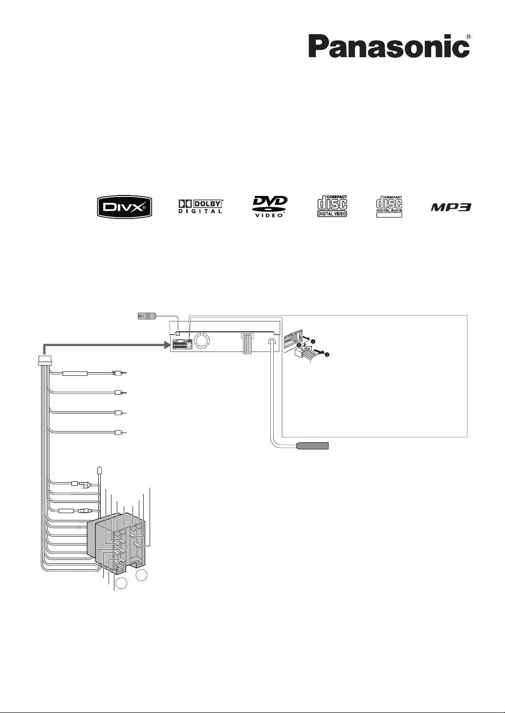
Wiring/Verdrahtung/Câblage/Bedrading/Cablaggio/Conexiones eléctricas
Fuse (15 A) Refer fuse replacement to your nearest authorized
Panasonic Service Centre. Do not try fuse replacement by yourself.
Sicherung (15 A) Wenden Sie sich zum Austausch der Sicherung
an eine autorisierte Panasonic-Kundendienststelle in Ihrer Nähe.
Versuchen Sie nicht, den Austausch selbst vorzunehmen.
Fusible (15 A) Confier le remplacement de fusible au centre de
service de service après-vente Panasonic agréé le plus proche.
N’essayez pas de remplacer le fusible tout(e) seul(e).
Zekering (15 A) Laat het vervangen van de zekering over aan uw
dichtstbijzijnde Panasonic service-centrum. Probeer in geen geval
zelf de zekering te vervangen.
Fusibile (15 A) Per la sostituzione del fusibile rivolgersi al più
vicino Centro di Assistenza Panasonic autorizzato. Non tentare di
sostituire il fusibile da sé.
Fusible (15 A) Solicite el reemplazo del fusible al centro de
servicio Panasonic autorizado que le quede más cerca. No trate de
reemplazar usted mismo el fusible.
System-up Connector/System-Upgrade-Stecker/
Connecteur de mise à niveau de système/
Systeemuitbreidingsaansluiting/
Connettore di potenziamento del sistema/
Conector de mejora del sistema
Antenna/Antenne/Antenne/Antenne/Antenna/Antena
Altavoces
B8 : Trasero Izquierdo –
(Verde con franja negra)
B7 : Trasero Izquierdo + (Verde)
B6 : Frontal Izquierdo –
(Blanco con franja negra)
B5 : Frontal Izquierdo + (Blanco)
B4 : Frontal Derecho –
(Gris con franja negra)
B3 : Frontal Derecho + (Gris)
B2 : Trasero Derecho –
(Violeta con franja negra)
B1 : Trasero Derecho + (Violeta)
Speakers
B8 : Rear Left –
(Green/black stripe)
B7 : Rear Left + (Green)
B6 : Front Left –
(White/black stripe)
B5 : Front Left + (White)
B4 : Front Right –
(Gray/black stripe)
B3 : Front Right + (Gray)
B2 : Rear Right –
(Violet/black stripe)
B1 : Rear Right + (Violet)
Lautsprecher
B8 : Hinten Links –
(
Grün mit schwarzem Streifen
)
B7 : Hinten Links + (Grün)
B6 : Vorne Links –
(
Weiß mit schwarzem Streifen
)
B5 : Vorne Links + (Weiß)
B4 : Vorne Rechts –
(
Grau mit schwarzem Streifen
)
B3 : Vorne Rechts + (Grau)
B2 : Hinten Rechts –
(
Violett mit schwarzem Streifen
)
B1 : Hinten Rechts + (Violett)
Haut-parleurs
B8 : Arrière Gauche –
(Vert à rayures noires)
B7 : Arrière Gauche + (Vert)
B6 : Avant Gauche –
(Blanc à rayures noires)
B5 : Avant Gauche + (Blanc)
B4 : Avant Droit –
(Gris à rayures noires)
B3 : Avant Droit + (Gris)
B2 : Arrière Droit –
(Violet à rayures noires)
B1 : Arrière Droit + (Violet)
luidsprekers
B8 : Achter Links –
(Groen met zwarte streep)
B7 : Achter Links + (Groen)
B6 : Voor Links –
(Wit met zwarte streep)
B5 : Voor Links + (Wit)
B4 : Voor Rechts –
(Grijs met zwarte streep)
B3 : Voor Rechts + (Grijs)
B2 : Achter Rechts –
(Paars met zwarte streep)
B1 : Achter Rechts + (Paars)
Altoparlanti
B8 : Posteriore Sinistro –
(Verde con riga nera)
B7 : Posteriore Sinistro + (Verde)
B6 : Anteriore Sinistro –
(Bianco con riga nera)
B5 : Anteriore Sinistro + (Bianco)
B4 : Anteriore Destro –
(Grigio con riga nera)
B3 : Anteriore Destro + (Grigio)
B2 : Posteriore Destro –
(Viola con riga nera)
B1 : Posteriore Destro + (Viola)
A4 : Battery Lead (Yellow)
A5 : Motor Antenna Relay Control Lead (Blue)
A7 : Power Lead (IGN or ACC) (Red)
A8 : Ground Lead (Black)
A4 : Batteriekabel (Gelb)
A5 : Steuerkabel für Relais der motorbetriebenen Antenne (Blau)
A7 : Versorgungskabel (IGN oder ACC) (Rot)
A8 : Massekabel (Schwarz)
A4 : Fil de batterie (Jaune)
A5 : Fil de commande de relais de moteur d’antenne (Bleu)
A7 : Fil d’alimentation (IGN ou ACC) (Rouge)
A8 : Fil de masse (Noir)
A4 : Accudraad (Geel)
A5 : Antennemotorrelais-stuurdraad (Blauw)
A7 : Stroomdraad (IGN of ACC) (Rood)
A8 : Massadraad (Zwart)
A4 : Cavo batteria (Giallo)
A5 : Cavo di controllo relé antenna motorizzata (Blu)
A7 : Cavo di alimentazione (IGN o ACC) (Rosso)
A8 : Cavo di massa (Nero)
A4 : Cable de la batería (Amarillo)
A5 : Cable de control del relé de la antena motorizada (Azul)
A7 : Cable de la alimentación (IGN o ACC) (Rojo)
A8 : Cable de masa (Negro)
1 Side Brake (Parking Brake) Connection Lead
2 External Remote Control Lead
3 External Amplifier Control Power Lead
4 Reverse Lead
1 Handremdraad
2 Externe afstandsbedieningsdraad
3 Externe versterker stroomstuurdraad
4 Achteruit-draad
1 Verbindungskabel für Feststellbremse (Handbremse)
2 Leitungsdraht für externe Fernbedienung
3 Stromsteuerkabel des externen Verstärkers
4 Rückwärtsgangkabel
1
Fil de connexion de frein à main (frein de stationnement)
2 Fil de la télécommande extérieure
3 Fil d’alimentation pour commande d’amplificateur
extérieur
4 Fil de marche arrière
1 Cavo di collegamento del freno a mano (freno di stazionamento)
2 Cavo di telecomando esterno
3 Cavo alimentazione controllo amplificatore esterno
4
Cavo di retromarcia
1 Cable de conexión del freno de mando (freno de estacionamiento)
2 Cable de control remoto externo
3 Cable de alimentación de control de amplificador externo
4 Cable de marcha atrás
(Bright green) (Leuchtend grün) (Vert clair)
(Lichtgroen) (Verde chiaro) (Verde claro)
(Brown/black stripe) (Braun mit schwarzem Streifen) (Brun à rayures noires)
(Bruin met zwarte streep) (Marrone con riga nera) (Marrón con franja negra)
(Blue/white stripe) (Blau mit weißem Streifen) (Bleu à rayures blanches)
(Blauw met witte streep) (Blu con riga bianca) (Azul con franja blanca)
(Violet/white stripe) (Violett mit weißem Streifen)
(Violet à rayures blanches) (Paars met witte streep)
(Viola con riga bianca) (Violeta con franja blanca)
¡Please read these instructions carefully before using this product and keep this manual for future reference.
¡Bitte lesen Sie diese Bedienungsanleitung vor der Verwendung dieses Produktes aufmerksam durch und bewahren Sie sie danach für spätere Nachschlagzwecke sorgfältig
auf.
¡Prière de lire ces instructions attentivement avant d’utiliser le produit et garder ce manuel pour l’utilisation ultérieure.
¡
Leest u deze instructie alstublieft zorgvuldig door voor u dit product in gebruik neemt en bewaar deze handleiding voor later gebruik.
¡
Si prega di leggere attentamente queste istruzioni prima di usare questo prodotto e di conservare questo manuale per usi futuri.
¡Lea con atención estas instrucciones antes de utilizar el producto y guarde este manual para poderlo consultar en el futuro.
Installation Instructions
Einbauanleitung
Instructions d’installation
Installatiehandleiding
Istruzioni per l’installazione
Instrucciones de instalación
TEXT
Model: CQ-VX100N
1
2
CQ-VX100N
English
Safety Information
CAUTION:
• PLEASE FOLLOW THE LAWS AND REGULATIONS
OF YOUR STATE, PROVINCE OR COUNTRY FOR
INSTALLATION OF THE UNIT.
• TO REDUCE THE RISK OF FIRE OR ELECTRIC
SHOCK OR PRODUCT DAMAGE, DO NOT EXPOSE
THIS APPLIANCE TO RAIN, SPLASHING, DRIPPING OR MOISTURE.
2
3
CQ-VX100N
English
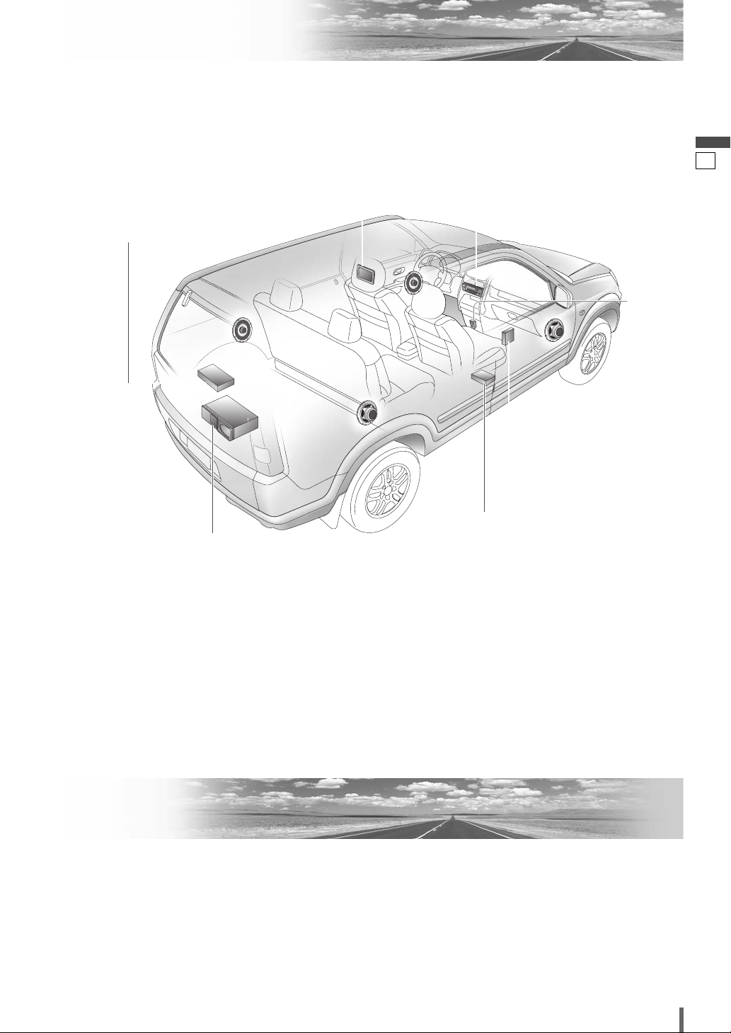
Upgrade Options
Safety Information................................................2
Upgrade Options..................................................3
Installation ............................................................4
Electrical Connections ......................................10
Contents
Main Unit
CQ-VX100N
Expansion Module
(CY-EM100N, option)
Hands Free Kit with Audio
Streaming featuring Bluetooth
®
technology
(Bluetooth unit: CY-BT200N,
option)
CD Changer
(CX-DP880N, option)
DVD Changer
(CX-DH801N, option)
Rear Monitor
iPod
®
TV Tuner
(CY-TUP153N, option)
3
4
CQ-VX100N
English
Installation
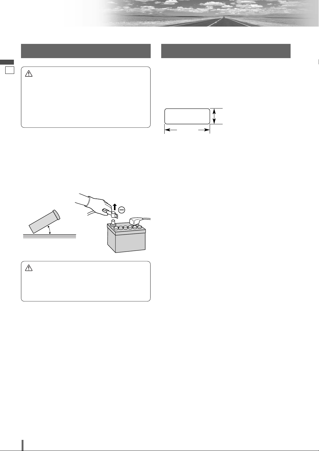
Preparation Dashboard Installation
¡Before installation, check the radio operation with
antenna and speakers.
¡Disconnect the cable from the negative (–) battery ter-
minal (see caution below).
¡The unit should be installed in a horizontal position
with the front end up at a convenient angle, but not
more than 30°.
Installation Opening
The unit can be installed in any dashboard having an
opening as shown below. The dashboard should be 4.5
mm – 6 mm thick in order to be able to support the unit.
Installation Precautions
This product should be installed by a professional
installer, if possible.
In case of difficulty, please consult your nearest authorized Panasonic Service Centre.
1. This system is to be used only in a 12 V DC battery
system (car) with negative ground.
2. Follow the electrical connections carefully (
a page
10-19). Failure to do so may result in damage to the
unit.
3. Connect the power lead after all other connections are
made.
4. Be sure to connect the battery lead (yellow) to the positive terminal (+) of the battery or fuse block (BAT) terminal.
5. Insulate all exposed wires to prevent short circuiting.
6. Secure all loose wires after installing the unit.
7. Please carefully read the operating and installation
instructions of the respective equipment before connecting it to this unit.
0 – 30°
182 mm
53 mm
Caution
¡Do not disconnect the battery terminals of a car with
trip or navigational computer since all user settings
stored in memory will be lost. Instead take extra
care with installing the unit to prevent shorts.
Caution
¡Please follow the laws and regulations of your
province or country for installation of the unit.
¡When bending the mounting tab of the mounting
collar with a screwdriver, be careful not to injure
your hands and fingers.
¡We strongly recommend you to wear gloves for
installation work to protect yourself from injuries.
4
5
CQ-VX100N
English
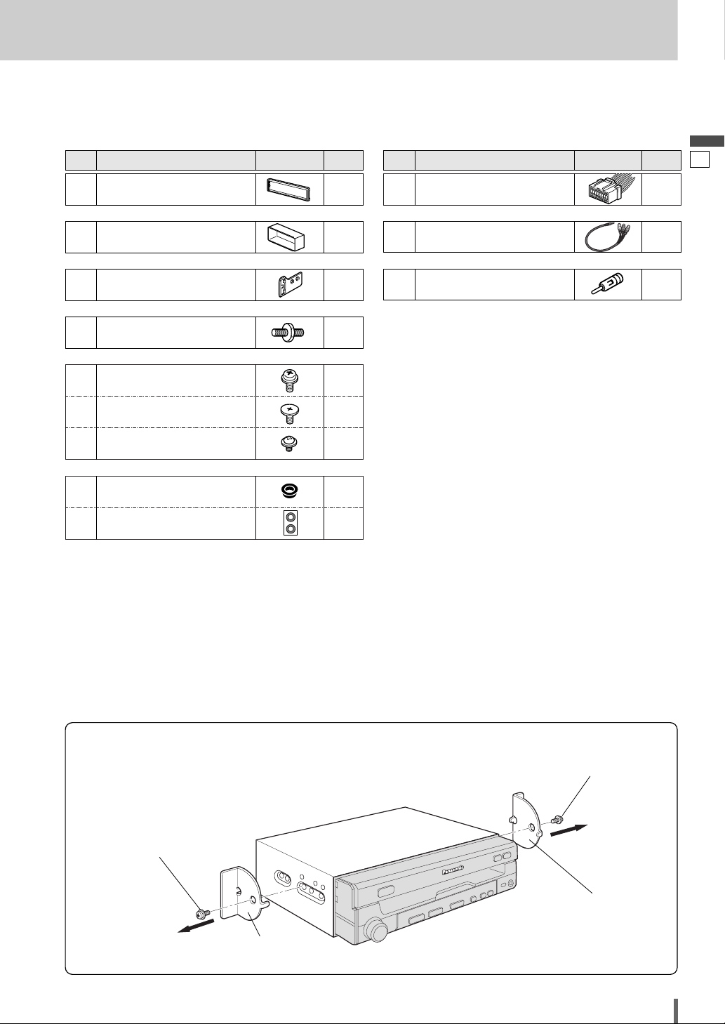
❏ Transportation Bracket Removal
Be sure to remove the transportation brackets before use (installation).
Use round head screws (5 mmø x 6 mm) for installation. (a page 8)
Be careful not to lose these screws.
Round Head Screw
(5
mmø x 6 mm)
Round Head Screw
(5
mmø x 6 mm)
Transportation
Bracket
Transportation
Bracket
❏ Installation Hardware
(For Installation)
Note:
¡The number in parenthesis underneath each accessory
part name is the part number for maintenance and service.
¡Accessories and their parts numbers are subject to
modification without prior notice due to improvements.
¡Use the supplied screws for installation exclusively. In
case of losing any of them, please order the specific
screw.
Qty.DiagramItemNo.
Trim Plate
<YFC054C087CA>
q
1
Mounting Collar
<YFX214C433CA>
w
1
Mounting Spring
<YFX054C077CA>
e
2
Mounting Bolt (5 mmø)
<YEJV014C002N>
r
1
<ZZBISVD7005E>
Spacer
i
2
Double-Faced Adhesive Tape
o
1
set
❏ Installation Hardware
(For
Wiring)
Qty.DiagramItemNo.
Conversion Cable for AV1 IN
<YEAERA33000K>
!1
1
<YAJ024C128CA>
Power Connector
!0
1
<ZZBISVD7005B>
Round Head Screw
(5 mmø x 6 mm)
t
2
Flat-Head Screw
(5 mmø x 6 mm)
y
4
Round Head Screw
(4 mmø x 3 mm)
u
4
ISO Antenna Adapter
(YEAA33144)
!2
1
5
6
CQ-VX100N
English
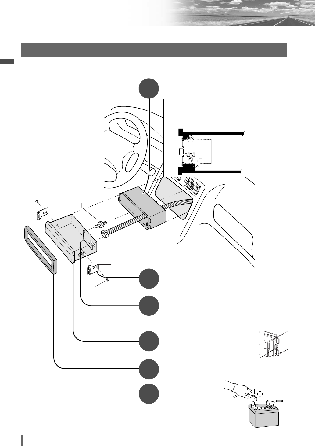
Installation (continued)
1
3
5
6
2
4
❏ Installation Procedures (When using Mounting Collar w)
Mounting the Main Unit
Insert the Mounting Collar w into the dashboard, and
bend the mounting tabs out with a screwdriver.
Establish the rear connection of the unit.
After fixing Power Connector !0, fix the rear of the unit to
the car body by either method (a) or (b) shown at right.
Insert Trim Plate q.
After installation
reconnect the negative
(–) battery terminal.
Attach the Mounting Springs
e to the unit.
!0
Power Connector
r Mounting Bolt
(5 mmø)
e Mounting Spring
y Flat-Head Screw
(5 mmø x 6 mm)
Note:
¡The car model, installation condi-
tions and combination of the units
used may impose some restrictions on opening and closing the
monitor as well as on the angle
and position to which the monitor
can be adjusted.
Fastening the Mounting Collar
How much to bend the tabs will vary depending on the
car. Bend them with a screwdriver to fasten the
Mounting Collar
w
securely in the dashboard.
w Mounting Collar
Dashboard
Tab
Insert the unit into Mounting Collar w.
Secure the clamp plate of Mounting Collar
w to the hook of Mounting Spring e.
Clamp plate
IMPORTANT
When this unit is installed in dashboard, ensure that there is sufficient
air flow around the unit to prevent
damage from overheating. Do not
block any ventilation holes on the
unit.
 Loading...