

Page 1

FUJINON LENS
XT17×4.5BRM-K14
OPERATION MANUAL
VQT2C46
Page 2

Before using this product, please read this operation manual carefully, and keep the
manual handy for future use.
Design and specications are subject to change without notice.
Page 3
FOR YOUR SAFETY USE
FOR YOUR SAFETY USE
is content explains important notices for all the users to use this product safely.Read the content carefully before
using, and follow the instructions.
e following signs of WARNING and CAUTION show:
WARNING
Indicates the possibility of causing death or serious injury when misused.
CAUTION
Indicates the possibility of causing injury or substantial damage when misused.
WARNING
◆ Do not moisten inside of the appliances. It may cause re or electric shock. If the incident occurs, shut o the power
supplied to the lens immediately.
◆ Be sure to attach all the parts securely. Dropping any parts from a height may cause severe accidents.
◆ Do not look at any sorts of strong illuminant such as the sun through the lens. Eyes could be harmed.
CAUTION
◆ Take care when carrying the lens. Dropping the lens while carrying may cause injury.
◆ Be sure to conrm that the camera to be used with the lens system (lens and accessories) is able to supply sucient
electric power to the lens system. If not, the lens system may not work normally and the camera will be damaged.
e values of the power consumption of the lens and the accessories are described in “Specications” section of
their operation manuals.
◆ Before supplying the power to the lens, make sure all the parts are connected correctly.
◆ In order to install or release a cable, be sure to hold the joint part. Do not damage the cable by gripping. It may
cause re or electric shock.
◆ If any sorts of incidents such as unusual smoke, noise, smell or obstacles are found, shut o the power supplied
to the lens and detach the lens from the camera immediately. Please notify our sales agent or Fujinon service
department as soon as possible.
◆ Do not remodel the instrument: it may impair the functions of product or cause electric shock.
E1464/R2
Page 4

FOR YOUR SAFETY USE
NOTICE
◆ Lens and its accessories are extremely precise instrument, then be sure not to apply the strong impacts to them. If
the lens is of a type in which the rear lens protrudes from the ange surface of the lens mount, be sure not to apply
impact to the lens part when installing or releasing.
◆ ere may be a case that the glasses of the lens mist when the lens is carried from a cool place to a place of high
temperature and high humidity. To avoid a mist on the glasses, before moving the lens, let the lens adjust to the
ambient temperature of the place where the lens will be used.
◆ Be sure not to apply impact to the front part of the lens when operating the camera.
◆ Put the cap on the lens while the camera is not used.
◆ If an accessory to be attached to the lens is equipped with a mechanical drive relaying part, before attaching it,
check the joint part and get rid of all obstacles. If there are any unusual conditions, please contact our sales agent or
Fujinon service department immediately.
◆ When the lens is used in the weather of fog, raining, or snowing, cover up the lens to prevent it from the water.
◆ To minimize the impact to the lens in transportation, set the zoom to the wide end and the focus to the innity side
end before releasing the lens from the camera.
E1464/R2
Page 5

TABLE OF CONTENTS
General Description ...................................................................................................................................................................... 2
•
Installation onto Camera ............................................................................................................................................................. 2
•
Adjustment of Flange Focal Length ...........................................................................................................................................3
•
Iris Adjustment .............................................................................................................................................................................. 5
•
Iris Operation ................................................................................................................................................................................ 6
•
Focus Operation ............................................................................................................................................................................ 7
•
Zoom Operation ............................................................................................................................................................................ 8
•
(1) Operation by Zoom Seesaw Control Lever ....................................................................................................................... 9
(2) QuickZoom Operation ........................................................................................................................................................ 9
(3) Auto Cruising Zoom Operation ....................................................................................................................................... 10
(4) Manual Operation .............................................................................................................................................................. 10
Macro Operation ......................................................................................................................................................................... 11
•
Other Functions .......................................................................................................................................................................... 12
•
About Function & Mode Select Switches ................................................................................................................................ 13
•
Attaching/Detaching Lens Hood ............................................................................................................................................. 14
•
Maintenance ................................................................................................................................................................................ 15
•
Optional Accessories .................................................................................................................................................................. 16
•
Specications ............................................................................................................................................................................... 18
•
Outline drawing
•
Note. e products shown in the illustrations in this manual may dier from their actual shapes.
RM-K1-T1 – 1 –
Page 6
GENERAL DESCRIPTION
is lens is a bayonet mount type zoom lens developed for a color TV Camera.
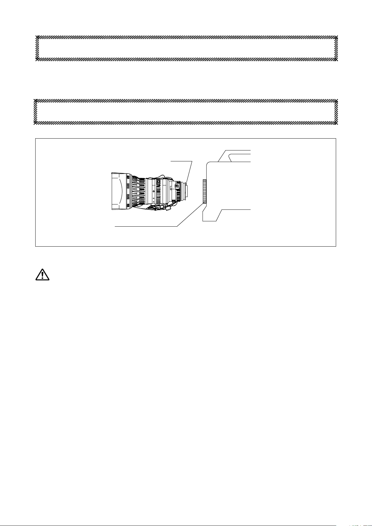
INSTALLATION ONTO CAMERA
PIN
CAMERA
MOUNT CLAMP RING
Note. Prior to installation of the lens, turn o the power of the camera.
WARNING
Be sure to attach all the parts securely. Dropping any parts from a height may cause severe accidents.
a. a. Take the rear lens cap o.
b. Rotate the mount clamp ring on the camera fully counterclockwise.
c. Fit the mounting surface of the lens to that of the camera aligning the pin on the lens with the slot in the camera.
d. Rotate the mount clamp ring fully clockwise.
e. Connect the cable of the lens to the connector, provided for the lens, on the camera.
Note. Make sure to adjust the ange focal length when installing the lens on a camera for the rst time or installing it
on another camera (refer to the next page for details).
If the ange focal length between the lens and the camera is not adjusted precisely, it will aect the shot because
the object will be out of focus during a zoom operation. Also, the optimal optical performance of the lens will
not be achieved.
– 2 –RM-K1
Page 7

ADJUSTMENT OF FLANGE FOCAL LENGTH
e ange focal length is the distance from the ange (mounting surface) of a lens to the focal plane.
If the focal plane of the lens does not coincide with the image plane of the camera, the object will be out of focus
during a zoom operation. To prevent this from happening, the adjustment of the ange focal length is required. Make
sure to carry out the adjustment when installing the lens to a camera for the rst time or installing it to another
camera.
Flange
Focal Plane
Flange Focal Length
CONDITIONS OF OBJECT AND DIAPHRAGM
1. Object: cut “Siemens Star” o at the end of this manual and use it as an object
2.
Distance of Object: about 3 meters
3.
Diaphragm: open or as near to open as possible
Note. e depth of eld decreases by opening the aperture of the lens, and it becomes possible to focus on an object
more precisely. To precisely adjust the ange focal length, carefully adjust the focus as much as possible.
– 3 –RM-K1
Page 8
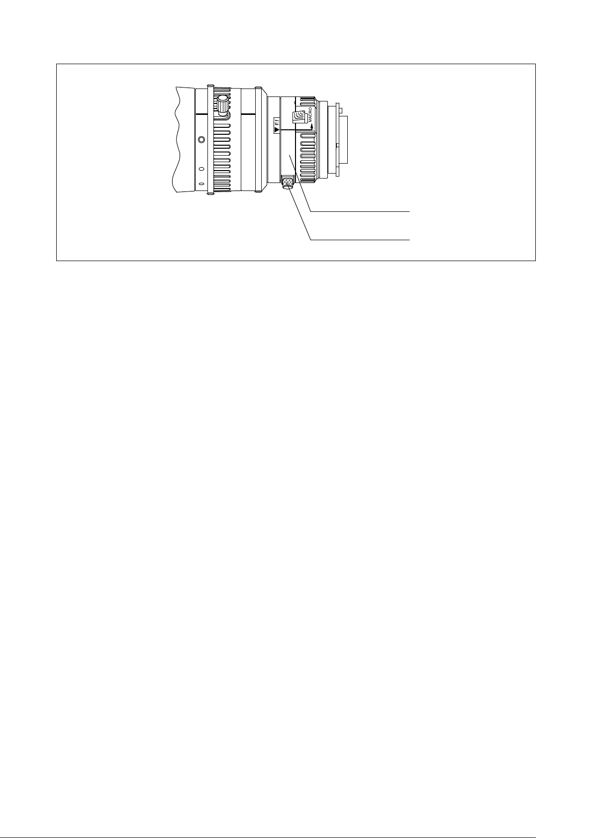
F.f ADJUSTING RING
F.f LOCKING KNOB
ADJUSTMENT
Aer installing the lens to the camera and turning it ON, perform adjustment by watching the monitor of the camera.
For the operation of focusing and zooming, refer to “Focus Operation” and “Zoom Operation” (pages 7 and 8).
a. Loosen the F.f locking knob by rotating it counterclockwise.
b. Operate the zoom to set it to the wide end.
c. Rotate the F.f adjusting ring using the F.f locking knob to focus on the Siemens Star located approximately 3 meters
away. e position where the radial black and white lines become sharpest is the optimum focus position.
d. Operate the zoom to set it to the telephoto end.
e. Operate the focus to bring the object into focus.
f. Operate the zoom to set it to the wide end again, and check that the optimum focus position adjusted in step ‘c’ is
kept.
g. To adjust precisely, repeat the above steps ‘b’ through ‘f ’ several times.
(If the most optimum focus position usually holds in all zoom areas, the ange focal length is adjusted precisely. If
it is not focused, the ange focal length is not adjusted suciently. In this case, start adjusting again from step ‘b.’)
h. Finally tighten the F.f locking knob rmly.
– 4 –RM-K1
Page 9
IRIS ADJUSTMENT
Since the iris is precisely adjusted at the factory before shipment, normally the readjustment is not required. But when
an abnormality occurs for some reason, the readjustment can be made as described below.
e adjusting trimmer becomes visible inside the drive unit by removing the cap at the front of the drive unit.
Use a small screwdriver or similar implement to rotate the trimmer.
IRIS SENSITIVITY ADJ. TRIMMER
IRIS SENSITIVITY ADJUSTMENT
Rotate the iris sensitivity adjusting trimmer clockwise for higher sensitivity and counterclockwise for lower sensitivity.
When obtaining higher sensitivity, be careful not to cause hunting.
RM-K1
– 5 –
Page 10

IRIS MOMENTARY SWITCH
IRIS MODE SELECT SWITCH
IRIS OPERATION
IRIS RING
ere are two iris operation modes: auto iris mode and manual mode. For the operating instruction in each mode,
refer to the description on each mode.
AUTO IRIS MODE
Set the iris mode select switch to “A.” e iris of the lens will automatically be adjusted responding to the object
brightness.
MANUAL MODE
a. Set the iris mode select switch to “M.”
b. Rotate the iris ring by hand to adjust the iris.
Clockwise rotation of the ring causes the iris to move toward the closed side and counterclockwise rotation toward
the open side.
Note. Although the iris operation mode is in Manual, the iris is adjusted automatically while the iris momentary
switch is being pressed.
– 6 –RM-K1
Page 11

FOCUS RING
FOCUS OPERATION
ATTACHING HOLE
FOR FOCUS MANUAL MODULE
Focusing can be done by directly rotating the focus ring by hand. Rotate the focus ring clockwise from the camera side
to focus on an object on the near side.
e remote control operation is also available with optional accessories.
– 7 –RM-K1
Page 12

ZOOM SEESAW CONTROL LEVER
ZOOM LEVER
ZOOM OPERATION
ATTACHING HOLE FOR ZOOM MANUAL MODULE
ZOOM SERVO/MANUAL SELECT KNOB
e zoom can be operated in the following four operation modes.
(1) Operation by Zoom Seesaw Control Lever ............................................................................................................................9
(2) QuickZoom Operation .............................................................................................................................................................9
(3) Auto Cruising Zoom Operation ............................................................................................................................................10
(4) Manual Operation .................................................................................................................................................................... 10
For the operating instruction in each mode, refer to the description on each mode.
e remote control operation is also available with optional accessories.
CONNECTOR FOR ZOOM CONTROL
ZOOM RING
Page
– 8 –RM-K1
Page 13

(1) Operation by Zoom Seesaw Control Lever
a. Set the zoom servo/manual select knob to “SERVO.”
b. Press the zoom seesaw control lever. Press T-side of the lever to zoom to the tele side, and the W-side to zoom to
the wide side. For the speed control, adjust the strength to press the lever. Pressing the lever deeply makes the zoom
speed faster, and shallowly makes slower.
(2) QuickZoom Operation
RETURN SWITCH
VTR SWITCH
In quickzoom operation, pressing a switch moves the zoom to the tele end quickly. e operator can use this function
in such occasions listed below.
When rapid zooming to the tele end is required to focus on the object precisely.
•
To conrm, in a moment, the composition of the image in the extreme closeup shot.
•
Either the VTR switch or the return switch can be used as a quickzoom switch. Set switch 1 or 2 in the area of
“Function & Mode Select Switches” (see page 13) to ON. When switch 1 is set to ON, the VTR switch acts as a
quickzoom switch, while when switch 2 is set to ON, the return switch acts as that switch. In the following description,
the VTR switch or the return switch is called quickzoom switch.
Operation
a. Set the zoom servo/manual select knob to “SERVO.”
b. Keep pressing the quickzoom switch until the zoom reaches the tele end.
c. While pressing the quickzoom switch, perform precise focusing or conrm the composition of the image in the
extreme closeup shot.
d. Release the quickzoom switch.
– e zoom will move to its former position quickly.
(If you press the quickzoom switch again before the zoom returns to its former position, the quickzoom
movement restarts. Aer this operation, if the switch is released, the zoom will move to its former position
quickly. )
Note 1. In quickzoom operation, the zoom moves at the maximum speed.
Note 2. If you press the quickzoom switch while pressing the zoom seesaw control lever, the zoom moves in auto
cruising zoom operation, not in quickzoom operation.
RM-K1
– 9 –
Page 14

(3) Auto Cruising Zoom Operation
In auto cruising zoom operation, the zoom moves to the tele end or the wide end at a constant speed. is function is
eective when a constant slow zoom speed is required across the zooming range.
Either the VTR switch or the return switch can be used as an auto cruizing zoom switch. Set switch 1 or 2 in the area
of “Function & Mode Select Switches” (see page 13) to ON. When switch 1 is set to ON, the VTR switch acts as an
auto cuizing zoom switch, while when switch 2 is set to ON, the return switch acts as that switch. In the following
description, the VTR switch or the return switch is called auto cuizing zoom switch.
Operation
a. Set the zoom servo/manual select knob to “SERVO.”
b. Press the zoom seesaw control lever and adjust the zoom speed.
c. While pressing the zoom seesaw control lever, press the auto crusing zoom switch.
– e auto cruising zoom function will work.
d. Release your hand from the zoom seesaw control lever.
– e zoom will move to the tele end or the wide end at a constant speed that is determined when the auto cruising
zoom switch is pressed.
Releasing
ere are three ways to release the auto cruising zoom operation mode.
1. Press the zoom seesaw control lever on the side of the direction of the zoom movement.
– When the amount of displacement of the zoom seesaw control lever exceeds that determined when the auto
cruising zoom operation is set, the auto cruising zoom operation mode will be released.
Aer released, the zoom will move continuously toward the same direction as moved before releasing. (In this
way, the auto cruising zoom operation mode can be released maintaining the smooth zoom movement.)
2. Press the zoom seesaw control lever on the reverse side of the direction of the zoom movement.
– e auto cruising zoom operation mode will be released immediately, and the zoom will move toward the reverse
direction.
3. Press the auto cruising zoom switch.
– e auto cruising zoom operation mode will be released immediately, and the zoom will stop.
(4) Manual Operation
a. Set the zoom servo/manual select knob to “MANUAL.”
b. Rotate the zoom ring directly or using the zoom lever.
Clockwise rotation of the zoom ring, viewed from the camera side, moves the zoom to the wide side, and
counterclockwise rotation to the tele side.
(When rotating the zoom ring directry, it is recommended to remove the zoom lever for smooth operation.)
RM-K1
– 10 –
Page 15

MACRO OPERATION
MACRO LEVER
MACRO RING
Carry out the following steps for the macro operation (taking a closeup shot).
a. Rotate the focus ring fully toward the innity side.
b. While pulling the macro lever toward the mount side, rotate the macro ring toward the arrow as far as it goes.
c. Focus the lens by controlling the zoom.
Note. It is also possible to shoot an object while the macro ring is in an intermediate position. In this case, the values
of the M.O.D. and the object area at M.O.D. are those of between a normal and a closeup shot.
PROCEDURE TO CANCEL
Rotate the macro ring in the opposite direction of the arrow until the macro lever automatically returns to its original
position.
– 11 –RM-K1
Page 16

Fig. A
Fig. B
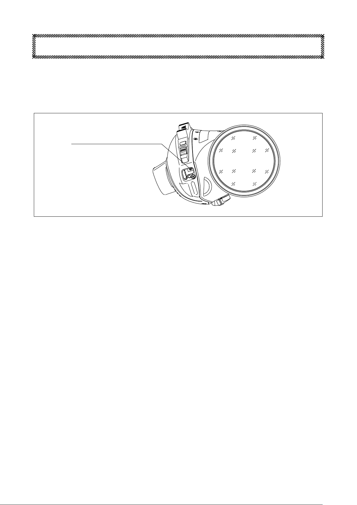
OTHER FUNCTIONS
VTR SWITCH
RETURN SWITCH
VTR Switch (Fig. A)
Operation of this switch starts or stops the VTR linked to the camera.
Note. If the setting of the function & mode select switches is properly arranged, this switch works as a quickzoom
switch or an auto cruising zoom switch. (refer to page 13)
Return Switch (Fig. B)
While pressing this switch, the return video picture can be seen through the viewnder of the camera.
Note. If the setting of the function & mode select switches is properly arranged, this switch works as a quickzoom
switch or an auto cruising zoom switch. (refer to page 13)
– 12 –RM-K1
Page 17

ABOUT FUNCTION & MODE SELECT SWITCHES
e function of some switches incorporated in this lens can be changed to other functions. e function can be
changed by setting switches in the function & mode select switches. e function & mode select switches are accessible
by removing the round rectangular rubber cap on the front of the drive unit.
FUNCTION & MODE SELECT SWITCHES
VTR à QUICKZOOM SELECT SWITCH
CAP REMOVED
RETURN à QUICKZOOM SELECT SWITCH
VTR, RETUKN FUNCTION CHANGE SWITCH
AUXILIARY SWITCH
The illustration shows the positions set at the factory.
(1) VTR à QuickZoom Select Switch
is switch changes the function of the VTR switch to that of the quickzoom switch. (e function of the VTR
switch incorporated in the zoom rate demand unit linked to this lens is also changed to that of the quickzoom
switch.)
(2) Return
is switch changes the function of the return switch to that of the quickzoom switch. (e function of the return
switch incorporated in the zoom rate demand unit linked to this lens is also changed to that of the quickzoom
switch.)
(3) VTR, Return Function Change Switch
e functions of the VTR switch and the return switch can be changed to each other.
à QuickZoom Select Switch
Setting of Switch Function of VTR Switch Function of Return Switch
OFF VTR Switch Return switch
(4) Auxiliary Switch
An auxiliary switch.
RM-K1
ON Return switch VTR Switch
– 13 –
Page 18

ATTACHING/DETACHING LENS HOOD
LENS HOOD
e lens hood enclosed with the product decreases the extra light entering the lens in shooting. To use it, attach it to
the front of the lens in the following procedure.
ATTACHING
a. Align FREE index on the lens hood with the index point on the focus ring and insert the lens hood into the focus
ring.
LOCK INDEX
FREE INDEX
INDEX MARK
b. Rotate the lens hood clockwise from the front view of the lens until it clicks.
DETACHING
a. Rotate the lens hood counterclockwise from the front view of the lens so that FREE index on the lens hood is
aligned with the index point on the focus ring. (It may be necessary to rotate strongly since there is a positioning
stopper inside.)
b. Pull the lens hood to remove.
RM-K1
– 14 –
Page 19

MAINTENANCE
CLEANING THE LENS
Prepare lens cleaning liquid and lens cleaning paper on the market.
a. First use a so brush or blower brush to brush dust o the surface of the lens.
b. Fold the cleaning paper to an adequate size, and dip a part of it into the liquid. Lightly wipe the lens from the center
to the periphery while drawing a spiral with the wet paper part. Repeat this operation using new paper until the
lens is thoroughly cleaned.
REMOVING THE MOISTURE
When the lens main body is wet, rst wipe the water on the external part with dry cloth immediately. en put it
together with desiccant into a vinyl bag for sealing to remove the moisture inside.
STORAGE
If it is assumed that the lens will not be used for a long term, store it in a place where high temperature, much moisture
or corrosive gas is absent.
CAUTION
is lens is composed of the optical unit and drive unit.
Never remove the screws that fasten these two units. If the units are separated, it will be required to readjust
mechanism in the drive unit.
INSPECTION
If an abnormality occurs on the lens, contact our sales agent or Fujinon service department.
To maintain the high performance for a long term for use, we recommend that a periodic inspection is conducted at
least once a year.
Note that we may not be able to inspect and repair our products which have been remodeled on the user’s end.
RM-K1
– 15 –
Page 20

OPTIONAL ACCESSORIES
All Manual System (Manual Focus, Manual Zoom)
ACCESSORY NAME MODEL REMARKS
Focus Manual Module FMM-6B Manual module for driving focus.
Focus Grip CFH-3 Grip for focus manual operation.
Zoom Manual Module ZMM-6 Manual module for driving zoom.
Zoom Handle CZH-14 Handle for zoom manual operation.
Flexible Cable CFC-12-990 For mechanical connection either between lens and
CFH or between lens and CZH.
Mounting Clamp MCA-7 Used with either CFH or CZH for its installation.
Conguration All Manual System
ZOOM MANUAL MODULE
ZMM-6
FLEXIBLE CABLE
CFC-12-990
FOCUS GRIP
CFH-3
LENS
FOCUS MANUAL MODULE
FMM-6B
FLEXIBLE CABLE
CFC-12-990
ZOOM HANDLE
CXH-14
MOUNTING CLAMP
MCA-7
RM-K1
– 16 –
Page 21

Zoom Servo System
ACCESSORY NAME MODEL REMARKS
Zoom Rate Demand Unit SRD-92B Control unit for zoom operation.
Conguration Zoom Servo System
LENS
ZOOM RATE DEMAND UNIT
SRD-92B
RM-K1
– 17 –
Page 22

SPECIFICATIONS
LENS
ITEM
Application 1/3” Format Color Camera (Prism Optical System)
Focal Length 4.5 – 77 mm
Zoom Ratio 17x
Maximum Relative Aperture (F No.) F1.6 (4.5 – 77 mm)
Maximum Photometric Aperture (T No.) T1.7
Iris Range F1.6 - F16, / Closed
Image Format 5.23 x 2.94 mm (Ø6.0 mm)
Flange Focal Length (in air) 31 mm (Adjustable Range: ±0.4 mm)
Minimum Object Distance 0.95 m (0.05 m in macro operation)
Ver.
Diag.
Rear
60° 19’ – 3° 53’
36° 11’ – 2° 11’
67° 23’ – 4° 28’
500 x 281 mm
30 x 17 mm
70.5 mm
20.1 mm
Field Angle Hor.
Object Area at M.O.D. at Wide End
at Tele End
Clear Aperture of Lens Front
XT17 x 4.5BRM
Filter Screw M82 x 0.75
Iris Control Servo or Manual
Zoom Control Servo (Op. Time: 1.0 - 15 s) or Manual
Focus Control Manual
Mount Bayonet Mount
Current Consumption (at 12V DC)
Mass (without Lens Hood) 1.28 kg (Approx.)
80 mA (Quiescent)
310 mA (Maximum)
– 18 –RM-K1
Page 23

VTR SWITCH
CABLE TO CAMERA
PIN
(UNLESS OTHERWISE SPECIFIED) UNIT: mm
CABLE TO CAMERA
(CONNECTOR: SN-10-12P Sam Woo)
MOUNT
INDEX MARK
RETURN SWITCH
GLASS ELEMENTS
MACRO RING
ZOOM SEESAW CONTROL LEVER
HAND BAND
MACRO LEVER
F.f BASE MARK
F.f ADJ. RING
F.f LOCKING KNOB
IRIS RING (OP ANGLE: 76°)
Outline drawing
XT17×4.5BRM-K14
CONNECTOR FOR ZOOM CONTROL (R03-R8F3 TAJIMI)
ZOOM RING (OP ANGLE: 90°)
INDEX LINE
ZOOM LEVER
LENS HOOD
IRIS MOMENTARY SWITCH
IRIS MODE SELECT SWITCH
P DETAIL
FUNCTION & MODE SELECT SWITCHES
IRIS SENSITIVITY ADJ. TRIMMER
MODULE ATTACHING HOLE
MODULE ATTACHING HOLE
ZOOM SERVO/MANUAL SELECT KNOB
FOCUS RING (OP ANGLE: 144°30’)
Page 24

Page 25

CUT LINE
SIEMENS STAR
Page 26

Page 27

Page 28

H0000000
 Loading...