

Page 1
This product is eligible for the AVCCAM
3 Year Warranty Repair Program. For
details, see page 7.
Before use
Operating Instructions
Memory Card Portable Recorder
of parts
Model No. AG-HMR10P
Model No. AG-HMR10E
Before operating this product, please read the instructions carefully and save this manual
for future use.
S0809S0 -M
ENGLISH
VQT2H54(E)
Reference Menu Displays Editing Playback Recording Preparation Description
Page 2
Read this first!
CAUTION
RISK OF ELECTRIC SHOCK
DO NOT OPEN
CAUTION: TO REDUCE THE RISK OF ELECTRIC
SHOCK, DO NOT REMOVE COVER (OR BACK).
NO USER-SERVICEABLE PARTS INSIDE.
REFER SERVICING TO QUALIFIED SERVICE
PERSONNEL.
The lightning flash with arrowhead symbol,
within an equilateral triangle, is intended to
alert the user to the presence of uninsulated
“dangerous voltage” within the product’s
enclosure that may be of sufficient magnitude
to constitute a risk of electric shock to persons.
The exclamation point within an equilateral
triangle is intended to alert the user to
the presence of important operating and
maintenance (servicing) instructions in the
literature accompanying the appliance.
WARNING:
To reduce the risk of fire or electric shock, •
do not expose this equipment to rain or
moisture.
To reduce the risk of fire or electric shock, •
keep this equipment away from all liquids.
Use and store only in locations which
are not exposed to the risk of dripping or
splashing liquids, and do not place any liquid
containers on top of the equipment.
WARNING:
Always keep memory cards out of the reach of
babies and small children.
CAUTION:
The mains plug of the power supply cord shall
remain readily operable.
The AC receptacle (mains socket outlet) shall be
installed near the equipment and shall be easily
accessible.
To completely disconnect this equipment from the
AC mains, disconnect the mains plug from the AC
receptacle.
indicates safety information.
CAUTION:
To reduce the risk of fire or electric shock and
annoying interference, use the recommended
accessories only.
CAUTION:
This apparatus can be operated at a voltage in
the range of 110 - 240 V AC.
Voltages other than 120 V are not intended for
U.S.A. and Canada.
Operation at a voltage other than 120 V
AC may require the use of a different AC
plug. Please contact either a local or foreign
Panasonic authorized service center for
assistance in selecting an alternate AC plug.
CAUTION:
A coin type battery is installed inside of the
unit.
Do not store the unit in temperatures over
60 °C (140 °F).
Do not leave the unit in an automobile
exposed to direct sunlight for a long period of
time with doors and windows closed.
CAUTION:
Danger of explosion or fire if battery is •
mistreated.
Do not leave the battery in an automobile •
exposed to direct sunlight for a long period
of time with doors and windows closed.
Do not disassemble the battery or dispose •
of it in fire.
Do not store the battery in temperatures over •
60°C (140°F).
Use specified charger.•
Replace battery only with same or specified •
type.
CAUTION:
Excessive sound pressure from earphones and
headphones can cause hearing loss.
CAUTION:
In order to maintain adequate ventilation, do
not install or place this unit in a bookcase,
built-in cabinet or any other confined space. To
prevent risk of electric shock or fire hazard due
to overheating, ensure that curtains and any
other materials do not obstruct the ventilation.
2
CAUTION:
Do not leave the unit in direct contact with the
skin for long periods of time when in use.
Low temperature burn injuries may be suffered
if the high temperature parts of this unit are
in direct contact with the skin for long periods
of time.
Page 3
IMPORTANT SAFETY INSTRUCTIONS
1) Read these instructions.
2) Keep these instructions.
3) Heed all warnings.
4) Follow all instructions.
5) Do not use this apparatus near water.
6) Clean only with dry cloth.
7) Do not block any ventilation openings. Install in accordance with the manufacturer’s instructions.
8) Do not install near any heat sources such as radiators, heat registers, stoves, or other apparatus
(including amplifiers) that produce heat.
9) Do not defeat the safety purpose of the polarized or grounding-type plug. A polarized plug has two
blades with one wider than the other. A grounding-type plug has two blades and a third grounding
prong. The wide blade or the third prong are provided for your safety. If the provided plug does not fit
into your outlet, consult an electrician for replacement of the obsolete outlet.
10) Protect the power cord from being walked on or pinched particularly at plugs, convenience
receptacles, and the point where they exit from the apparatus.
11) Only use attachments/accessories specified by the manufacturer.
12) Use only with the cart, stand, tripod, bracket, or table specified by the manufacturer,
or sold with the apparatus. When a cart is used, use caution when moving the cart/
apparatus combination to avoid injury from tip-over.
13) Unplug this apparatus during lightning storms or when unused for long periods of time.
14) Refer all servicing to qualified service personnel. Servicing is required when the
apparatus has been damaged in any way, such as power-supply cord or plug is damaged, liquid has
been spilled or objects have fallen into the apparatus, the apparatus has been exposed to rain or
moisture, does not operate normally, or has been dropped.
Portable Recorder
The rating plate is on the backside of the unit.
AC Adapter
The rating plate is on the underside of the AC Adapter.
Disconnect the AC mains plug from the AC mains socket when not in use.
Recommendation for Use of Genuine Panasonic Battery (Rechargeable Battery)
Thank you for using a Panasonic product.
It has been found that counterfeit battery packs which look very similar to the genuine product are
made available to purchase in some markets. Some of these battery packs are not adequately
protected with internal protection to meet the requirements of appropriate safety standards. There is
a possibility that these battery packs may lead to fire or explosion. Please be advised that we are not
liable for any accident or failure occurring as a result of use of a counterfeit battery pack. To ensure that
safe products are used we would recommend that a genuine Panasonic battery pack is used.
3
Page 4

Read this first! (continued)
For AG-HMR10E
indicates safety information.
Caution for AC Mains Lead
FOR YOUR SAFETY PLEASE READ THE FOLLOWING TEXT CAREFULLY.
This product is equipped with 2 types of AC mains cable. One is for continental Europe, etc. and the
other one is only for U.K.
Appropriate mains cable must be used in each local area, since the other type of mains cable is
not suitable.
FOR CONTINENTAL EUROPE, ETC.
Not to be used in the U.K.
FOR U.K. ONLY
This appliance is supplied with a moulded three
pin mains plug for your safety and convenience.
A 5 amp fuse is fitted in this plug.
Should the fuse need to be replaced please
ensure that the replacement fuse has a rating of
5 amps and that it is approved by ASTA or BSI
to BS1362.
Check for the ASTA mark
on the body of the fuse.
or the BSI mark
FOR U.K. ONLY
How to replace the fuse
1. Open the fuse compartment with a
screwdriver.
If the plug contains a removable fuse cover you
must ensure that it is refitted when the fuse is
replaced.
If you lose the fuse cover the plug must not be
used until a replacement cover is obtained.
A replacement fuse cover can be purchased
from your local Panasonic Dealer.
4
2. Replace the fuse
Fuse
Page 5

indicates safety information.
FCC NOTICE (USA)
Declaration of Conformity
Model Number: AG-HMR10P
Trade Name: Panasonic
Responsible Party: Panasonic Corporation of North America
Support contact: Panasonic Broadcast & Television Systems Company
This device complies with Part 15 of the FCC Rules.
Operation is subject to the following two conditions:
(1)This device may not cause harmful interference, and (2) this device must accept any interference
received, including interference that may cause undesired operation.
To assure continued compliance, follow the attached installation instructions and do not make any
unauthorized modifications.
One Panasonic Way, Secaucus, NJ07094
1-800-524-1448
Note:
This equipment has been tested and found to comply with the limits for a class B digital device,
pursuant to Part 15 of the FCC Rules. These limits are designed to provide reasonable protection
against harmful interference in a residential installation. This equipment generates, uses, and can
radiate radio frequency energy, and if not installed and used in accordance with the instructions,
may cause harmful interference to radio communications. However, there is no guarantee
that interference will not occur in a particular installation. If this equipment does cause harmful
interference to radio or television reception, which can be determined by turning the equipment off
and on, the user is encouraged to try to correct the interference by one of the following measures:
Reorient or relocate the receiving antenna. •
Increase the separation between the equipment and receiver. •
Connect the equipment into an outlet on a circuit different from that to which the receiver is •
connected.
Consult the dealer or an experienced radio/TV technician for help. •
The user may find the booklet “Something About Interference” available from FCC local regional
offices helpful.
Warning:
To assure continued FCC emission limit compliance, follow the attached installation instructions and
the user must use only shielded interface cables when connecting to host computer or peripheral
devices. Also, any unauthorized changes or modifications to this equipment could void the user’s
authority to operate this device.
NOTIFICATION (Canada)
This class B digital apparatus complies with Canadian ICES-003.
5
Page 6

EMC NOTICE FOR THE PURCHASER/USER OF THE APPARATUS
1. Applicable standards and operating environment (AG-HMR10E)
The apparatus is compliant with:
• standards EN55103-1 and EN55103-2 1996.11, and
• electromagnetic environments E1, E2, E3 and E4
2. Pre-requisite conditions to achieving compliance with the above standards
<1> Peripheral equipment to be connected to the apparatus and special connecting cables
• The purchaser/user is urged to use only equipment which has been recommended by us as
peripheral equipment to be connected to the apparatus.
• The purchaser/user is urged to use only the connecting cables described below.
<2> For the connecting cables, use shielded cables which suit the intended purpose of the
apparatus.
• Video signal connecting cables
Use double shielded coaxial cables, which are designed for 75-ohm type high-frequency applications,
for SDI (Serial Digital Interface).
Coaxial cables, which are designed for 75-ohm type high-frequency applications, are recommended
for analog video signals.
• Audio signal connecting cables
If your apparatus supports AES/EBU serial digital audio signals, use cables designed for AES/EBU.
Use shielded cables, which provide quality performance for high-frequency transmission applications,
for analog audio signals.
• Other connecting cables (IEEE1394, USB)
Use shielded cables, which provide quality performance for high-frequency applications, as
connecting cables.
• When connecting to the DVI signal terminal, use a cable with a ferrite core.
• If your apparatus is supplied with ferrite core(s), they must be attached on cable(s) following
instructions in this manual.
3. Performance level
The performance level of the apparatus is equivalent to or better than the performance level required by
these standards.
However, the apparatus may be adversely affected by interference if it is being used in an EMC environment,
such as an area where strong electromagnetic fields are generated (by the presence of signal transmission
towers, cellular phones, etc.). In order to minimize the adverse effects of the interference on the apparatus in
cases like this, it is recommended that the following steps be taken with the apparatus being affected and
with its operating environment:
1. Place the apparatus at a distance from the source of the interference.
2. Change the direction of the apparatus.
3. Change the connection method used for the apparatus.
4. Connect the apparatus to another power outlet where the power is not shared by any other
appliances.
6
Page 7

For USA and Canada
A lithium ion/polymer battery that is recyclable powers the product you have purchased.
Please call 1-800-8-BATTERY for information on how to recycle this battery.
To remove the battery
Main Power Battery
(Refer to page 25 for the detail.)
Press the battery release button.
Back-up Battery (Lithium Battery)
For the removal of the battery for disposal at the
end of its service life, please consult your dealer.
Battery release button
EEE Yönetmeliğine Uygundur.
EEE Complies with Directive of Turkey.
Thank you for purchasing this Panasonic AVCCAM device.
Register as a user for this device to receive a special service warranty up to three years of free warranty repairs.
AVCCAM 3 Year Warranty Repair Program*
Customers who register as users on the website will receive an extended warranty repair valid for up to
three years.
1st year 2nd year 3rd year
AVCCAM device
*1: Please note that this extended warranty is not available in some countries/regions. *2: Not all models eligible for extended
warranty coverage. *3: The basic warranty period may vary depending on the country/region. *4: Not all repair work is
covered by this extended warranty.
*
2
Basic warranty
3
*
Extended warranty repair
1
4
*
Free 3 years of Warranty Repairs
Make sure to save the “Registration Notice” e-mail
Purchase
AVCCAM product
Details about user registration and the extended warranty: http://panasonic.biz/sav/pass_e
Please note, this is a site that is not maintained by Panasonic Canada Inc. The Panasonic Canada Inc. privacy policy does not apply and is not applicable in relation to any
information submitted. This link is provided to you for convenience.
Register online
within 1 month
“Registration Notice”
e-mail sent
during the warranty period.
7
Page 8

EU
The SDHC logo is a trademark. ●
The miniSD logo is a trademark. ●
“AVCHD” and the “AVCHD” logo are trademarks of Panasonic Corporation and Sony Corporation. ●
This product has been manufactured under license from Dolby Laboratories. ●
Dolby and the double-D symbol are trademarks of Dolby Laboratories.
HDMI, the HDMI logo, and High-Definition Multimedia Interface are trademarks or registered trademarks ●
of HDMI Licensing LLC.
Microsoft®, Windows®, and Windows Vista® are either registered trademarks or trademarks of ●
Microsoft Corporation in the United States and/or other countries.
Screenshots are used in accordance with Microsoft Corporation guidelines. ●
IBM and PC/AT are registered trademarks of International Business Machines Corporation. ●
Intel® is a registered trademark or a trademark of Intel Corporation in the United States and/or other ●
countries.
Macintosh® is a trademark of Apple Inc., registered in the United States and other countries. ●
Other model names, company names, and product names listed in these operating instructions are ●
trademarks or registered trademarks of their respective companies.
This product is licensed under the AVC Patent Portfolio License for the personal and non-commercial ●
use of a consumer, and no license is granted or shall be implied for any use other than the personal
uses detailed below.
– To encode video in compliance with the AVC standard (“AVC Video”)
– To decode AVC Video that was encoded by a consumer engaged in a personal and non-commercial activity
– To decode AVC Video that was obtained from a video provider licensed to provide AVC Video
• Additional information may be obtained from MPEG LA, LLC (http://www.mpegla.com).
– Separate license contracts must be obtained from MPEG LA where SD Memory Cards containing information
recorded with this product are to be distributed to end users for commercial purposes. “End user” refers to
persons or organizations handling such contents for personal use.
Note concerning illustrations in these instructions
Illustrations (portable recorder, menu screens, etc.) in these operating instructions differ slightly from the •
actual portable recorder.
References
References are shown as (Page 00).•
Terminology
Both SD Memory Cards and SDHC Memory Cards are referred to as “SD Memory Cards” in these •
operating instructions.
Video data created in one recording operation is called a “clip”.•
The optional compact camera head (AG-HCK10G) is referred to as “camera head” in these operating •
instructions.
8
Page 9

Using the portable recorder
This memory card portable recorder is an AVCCAM recording and playback device that is compact and
can be powered by a battery. It is equipped with an SD Memory Card slot, a 3.5-inch LCD monitor, and a
wide range of input and output terminals, such as SDI, HDMI, USB 2.0 and CAMERA (for connecting the
AG-HCK10G optional camera head). In addition to enabling the easy playback of content shot with an
AVCCAM camera-recorder, this device supports backup recording and file management on SD Memory
Cards, and making recordings in outdoor locations.
Recording onto an SD Memory Card
HD-SDI input recording (Page 36)
1
When the portable recorder is connected to an external device that is equipped with HD-SDI output, data
can be recorded onto an SD Memory Card.
In addition, operations for starting or stopping recording on the portable recorder can be performed from
some types of camera-recorder. (When SDI input is selected.)
(For details on the compatible devices, see page 85.)
AG-HMR10 (portable recorder)
Camera recorder
HD-SDI signal
Shooting with a camera (Page 37)
2
When the portable recorder is connected to the AG-HCK10G camera head (optional), data can be
recorded onto an SD Memory Card.
Camera functions for the camera head, such as zoom, focus and iris, can be performed with manual •
operations on the portable recorder.
AG-HMR10 (portable recorder)
AG-HCK10G camera head
(optional)
Camera cable
(optional)
SD Memory Card
32
SD Memory Card
32
9
Page 10

Using the portable recorder (continued)
Playing SD Memory Card content
Playback on the portable recorder’s LCD monitor
3
(Page 58)
Content (video/audio) that is shot with an AVCCAM camera-recorder and recorded onto an SD Memory
Card can be played back on-the-spot.
AG-HMR10
AVCCAM camera-recorder
SD Memory Card
32
(portable recorder)
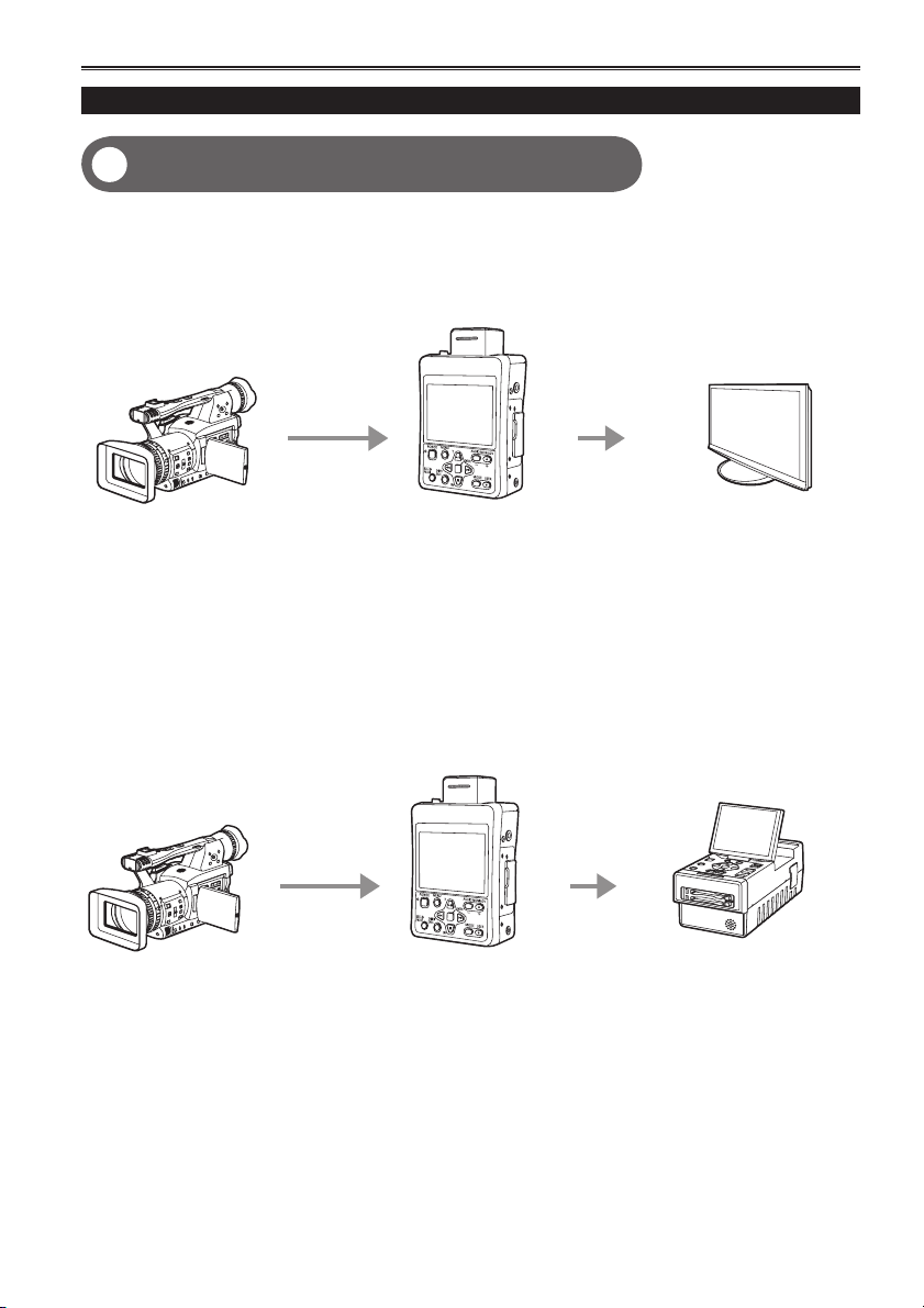
Outputting to an external monitor for playback
4
(Page 70)
Content (video/audio) on an SD Memory Card can be output to an external monitor for playback.
AG-HMR10
SD Memory Card
(portable
recorder)
External monitor
32
Use the HD-SDI output of content that is recorded and played in AVCCAM format only for outputting to •
an external monitor.
HD-SDI output
HDMI output
Editing SD Memory Card content
Connecting to a computer for editing (Page 71)
5
The portable recorder can be connected to a computer with a USB connection, enabling content on the SD
Memory Card to be copied and edited with the computer.
AG-HMR10
(portable recorder)
SD Memory Card
32
USB 2.0 cable
Computer
10
Page 11
HD-SDI output
Example of system configuration for SDI mode
6
When outputting data in the portable recorder’s recording format ■
Select [SDI EE SEL] → [NORMAL] in the [AV OUT SETUP] setup menu.
Using the setup menus (Page 29)•
AG-HMR10 (portable recorder)
Camera-recorder
HD-SDI input signal
Data such as information in the OSD and menu screens can be added to the output signal.•
(When [OUTPUT OSD] → [ON] is selected in the [DISPLAY SETUP] setup menu.)
S-VITC/UMID information is not output.•
Use when performing checks on an external monitor.•
When outputting the input data unchanged
■
Select [SDI EE SEL] → [THROUGH] in the [AV OUT SETUP] setup menu.
Using the setup menus (Page 29)•
AG-HMR10 (portable recorder)
Camera-recorder
HD-SDI input signal
The HD-SDI input signal is output unchanged.•
Use when recording or editing is required on the output device.•
In PB mode, the setting switches automatically to [NORMAL].•
HD-SDI output signal
HD-SDI output
signal
External monitor
External device, such as
a recorder
11
Page 12

Using the portable recorder (continued)
Example of system configuration for CAM mode
7
AG-HMR10 (portable recorder)
AG-HCK10G camera head
(optional)
Camera cable
(optional)
Frame sequence information is not output.•
S-VITC/UMID information is not output.•
Use when performing checks on an external monitor.•
External monitor
HD-SDI output signal
12
Page 13

Contents
Read this first! ................................................2
IMPORTANT SAFETY INSTRUCTIONS .........3
Recommendation for Use of Genuine
Panasonic Battery
(Rechargeable Battery) .......................... 3
Using the portable recorder ..........................9
Precaution for use ........................................ 15
Before use
Operating precautions ................................. 18
Accessories .................................................. 20
Optional accessories ...................................20
Description of parts
Description of parts ...................................... 21
Operation panel, LCD and system parts .........21
Terminals and system parts ............................. 22
Preparation
Power sources .............................................. 23
Charging .......................................................... 23
Using the battery .............................................25
Using the AC adapter ...................................... 25
Turning the power on/off ............................. 26
Tally lamp ...................................................... 27
SD Memory Card access lamp .................... 27
Operation modes .......................................... 28
Using the setup menus ................................ 29
Using the menus ............................................. 29
Initializing the setup menus ............................. 30
Setting the date and time/Recharging the
built-in battery/Adjusting the LCD
monitor .................................................. 31
Setting the date and time ................................ 31
Recharging the built-in battery ........................ 32
Adjusting the LCD monitor .............................. 32
SD Memory Cards......................................... 33
Inserting and removing SD Memory Cards .....33
Protecting SD Memory Cards .......................... 33
Repairing SD Memory Cards .......................... 34
Formatting SD Memory Cards ......................... 34
SD Memory Card recording times ................... 35
Recording
Recording onto an SD Memory Card
(REC mode) ...........................................36
Performing HD-SDI input recording
(SDI mode) .................................................. 36
Shooting and recording with a camera
(CAM mode) ................................................ 37
Setting the time code ................................... 39
Setting the time code ....................................... 39
Specifying the time code (TC PRESET) .......... 39
Setting user information .................................. 40
Using the [USER] button .............................. 41
Useful recording and shooting functions .. 44
White balance and black balance adjustment
Adjusting the white balance and black balance
Using focus assist (FA) .................................... 46
Wave form monitor (WFM) .............................. 46
Temporarily switching to auto focus mode
(ONE PUSH AF) .......................................... 46
Preventing accidental operation (KEY LOCK)
Turning off the LCD monitor screen (LCD OFF)
Adjusting the recording level of
the input audio (MIC LEV) ........................... 47
Color bar .......................................................... 47
Time stamp function ........................................ 47
Operating the camera head ......................... 48
Using the zoom function .................................. 48
Digital zoom function ....................................... 48
PRE REC ........................................................ 49
Optical Image Stabilizer .................................. 49
Performing manual adjustments
(CAMERA FUNCTIONS) ............................. 50
Shooting in progressive mode .................... 54
Clip metadata ................................................ 55
Uploading the metadata (META DATA) ........... 56
Selecting the USER CLIP NAME recording
method ........................................................ 57
... 45
... 45
... 46
... 47
13
Page 14

Contents (continued)
Playback
Clip playback (PB mode) .............................58
Thumbnail screen ......................................... 59
Playback settings (PLAY SETUP)................ 61
Setting the playback format (PB FORMAT) ..... 61
Repeat playback (REPEAT PLAY) .................. 61
Resume playback (RESUME PLAY) ............... 62
Setting the skip method (SKIP MODE)............ 62
Thumbnail operations .................................. 63
Selecting the thumbnail display method
(THUMBNAIL SETUP) ................................ 63
Deleting and protecting clips (OPERATION) ... 64
Formatting cards/Checking clip and card
information (CARD FUNCTIONS) ............... 65
Useful playback functions ........................... 67
Fast forward/rewind ......................................... 67
Next/previous clip ............................................ 67
Frame-by-frame playback ............................... 68
Adjusting the volume ....................................... 68
Viewing images on a television or monitor ...... 68
Editing
Connecting external devices ....................... 69
Using headphones .......................................... 69
Using the external microphone ........................ 69
Viewing images on a television or monitor ...... 70
Connecting to a computer
(nonlinear editing/file transfer) ..................... 70
Nonlinear editing (PC mode) ....................... 71
Menu
Setup menu structure ..................................80
Recording (REC) mode menu ......................... 80
Playback (PB) mode menu .............................. 81
Setup menu list ............................................. 82
CAMERA SETUP ............................................ 82
RECORDING SETUP ..................................... 84
TC/UB SETUP ................................................. 86
AV OUT SETUP .............................................. 87
DISPLAY SETUP ............................................. 88
CARD FUNCTIONS ........................................89
META DATA ..................................................... 89
PLAY SETUP ................................................... 90
THUMBNAIL SETUP ....................................... 90
OPERATION....................................................91
OTHER FUNCTIONS ...................................... 91
Reference
Troubleshooting ...........................................94
Updating the portable recorder ................... 98
Cleaning ........................................................ 98
Storage Precautions..................................... 98
Recording format list ...................................99
How to handle data recorded on
SD Memory Card ................................. 100
Specifications ............................................. 101
Index ............................................................ 103
Displays
Screen displays ............................................ 72
Regular displays .............................................. 72
Main warning displays ..................................... 76
Selecting the display items .............................. 78
Recording and output format
compatibility list ................................... 79
14
Page 15
Precaution for use
Always take some trial shots before actual shooting.
When shooting important events (such as weddings), always take some trial shots and check that the •
sound and images have been recorded properly before actual shooting.
Be sure to check and set the date, time and time zone.
These settings affect the control and playback sequence of the recorded contents. Before making a •
recording, set and check the date, time and time zone. (Page 31)
Panasonic makes no compensation for your recordings.
Please understand that Panasonic makes no compensation for your recordings in cases where images •
and/or sound were not recorded as you intended due to problems with the camera-recorder or SD/SDHC
Memory Cards.
Respect copyrights
Copyright laws forbid the use of video and audio material you have recorded for any purpose other than •
your own personal enjoyment. Remember that restrictions apply to the shooting of certain material even
if it is intended for private use.
Batteries that may be used with this product (Correct as of October 2009)
Panasonic VW-VBG260 battery may be used with this product. •
The VW-VBG260 battery contains a function to enable verification as to whether they may be safely used
with this product.
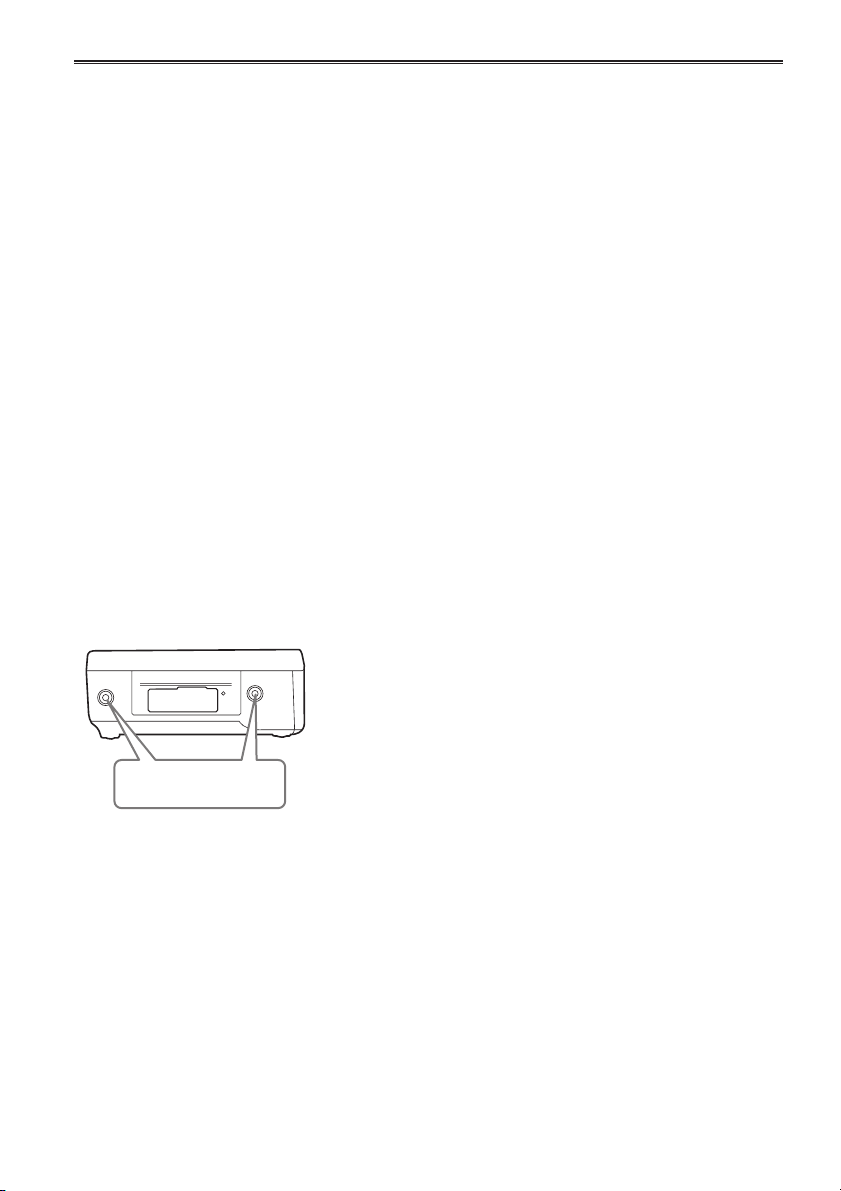
Multipurpose screw holes
M3 (3 mm diameter) type screws (length: 8 mm) can be used for the four screw holes at the sides of the •
portable recorder.
When using the screws, do not tighten them with excessive force. Use of screws other than the M3
(3 mm diameter) type screws (length: 8 mm) may damage the portable recorder.
Multipurpose screw
For other usage notes, see page 18.
holes
There are 2 more multipurpose screw holes on the opposite side.
(Continued on the next page)
15
Page 16

Precaution for use (continued)
Media that can be used in this unit
SD/SDHC Memory Cards can be used in this unit. •
It is recommended that you use SD Memory Cards or SDHC Memory Cards•
above, or the following Panasonic SD Memory Cards (correct as of October 2009).
∗
Speed class 4 or above is required for recording in PH mode or HA mode.
Card type Recording capacity Recording/playback Reading of metadata
SD Memory
Card
SDHC Memory
Card
8 MB
16 MB
32 MB
64 MB
128 MB
256 MB
512 MB RP-SDV512
1 GB
2 GB
4 GB
6 GB RP-SDM06G
8 GB
12 GB
16 GB
32 GB
Cannot be used.
Successful operation cannot be
guaranteed. Recording may be
suddenly terminated with certain
SD Memory Cards.
RP-SDV01G
RP-SDM01G
RP-SDV02G
RP-SDM02G
RP-SDP02G
RP-SDR02G
RP-SDV04G
RP-SDM04G
RP-SDW04G
RP-SDP04G
RP-SDR04G
RP-SDV08G
RP-SDM08G
RP-SDW08G
RP-SDP08G
RP-SDR08G
RP-SDM12G
RP-SDP12G
RP-SDV16G
RP-SDM16G
RP-SDW16G
RP-SDP16G
RP-SDV32G
RP-SDW32G
Please see our support page at the following website for the latest information not included in these •
operating instructions.
https://eww.pavc.panasonic.co.jp/pro-av/
This product is compatible with SD Memory Cards formatted under the SD-standard FAT12 and FAT16 •
formats, and with SDHC Memory Cards formatted under the FAT32 format.
Only SDHC Memory Cards may be used for capacities of 4 GB or greater.•
4 GB (or greater) memory cards without the SDHC logo are not based on the SD standard.•
Use this product to format the SD Memory Cards to be used. Formatting memory cards on computers •
or other devices may cause recording to take longer than normal, or may cause cards to become
incompatible with this product. (Page 34) (Use this product to reformat any cards that have already been
formatted on computers, etc.)
Always install the relevant special adapter when using miniSD/miniSDHC cards with this product. (The •
product will not operate correctly if only the adapter is inserted – always insert a memory card into the
adapter first.)
MultiMediaCards cannot be used with this product.•
∗
of SD speed class 2 or
Can be used.
16
Page 17
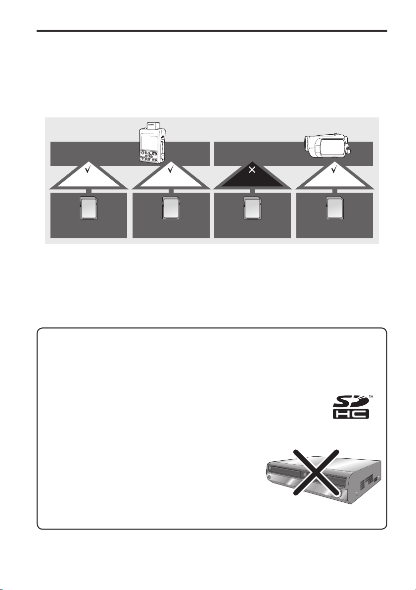
SDHC-compatible device
This product (SDHC-compatible device) is compatible both with SD Memory Cards and with SDHC •
Memory Cards. SDHC Memory Cards may be used with SDHC Memory Card-compatible devices, but
cannot be used with devices that are only compatible with SD Memory Cards. (Always check the relevant
product’s operating instructions when using SDHC Memory Cards with other devices.)
When cards of SD speed class 4 or above are recommended for the SD-compatible devices, use of such
cards will ensure stable recording operations.
SDHC-compatible
device
Can be used Can be used Cannot be used Can be used
SDHC Memory Card SD Memory Card SDHC Memory Card SD Memory Card
What is AVCHD? ■
AVCHD is a standard for the recording and playback of highly detailed, high-definition video.
Video is compressed in the MPEG-4 AVC/H.264 formats, and audio is recorded in Dolby Digital.
Information regarding compatibility of SDHC Memory Cards and recorded video ■
SDHC Memory Cards
SDHC Memory Cards cannot be used with non-SDHC-compatible equipment.•
Ensure that all equipment is SDHC-compatible when using card with other •
devices.
Compatibility of recorded video
Recorded video cannot be used with non-AVCHD-compatible •
equipment. For details, please see your product’s operating
instructions.
Recorded video cannot be played back on non-compatible •
(non-AVCHD-compatible) equipment.
Playback may not always be possible on all AVCHD-compatible •
equipment. Please use this product for playback in such
instances.
SD-compatible
device
Non-AVCHD-compatible DVD
recorder or DVD player, etc.
17
Page 18

Operating precautions
The portable recorder and SD card become
warm during usage. This is not a defect.
Do not allow any water to get into the unit when
using it in the rain or snow or at the beach.
Failure to heed this caution will cause the unit •
or a card to malfunction (and may result in
irreparable damage).
The portable recorder should be used as far
as possible from sources of magnetism and
electromagnetism (cell phones, microwave
ovens, TVs, game machines, etc.).
If the portable recorder is operated on top of or •
close to a TV, the electromagnetism can cause
distortion of audio and video.
Strong magnetism from speakers, large motors, etc. can •
cause recordings to be lost and video to be distorted.
Electromagnetic waves emitted from digital •
circuits, including microcomputers, can impact
each other, causing distortion of audio and video.
If the portable recorder is so adversely affected •
that it does not operate normally, remove the
battery or AC adaptor, reconnect them and turn
the power on again.
As much as possible, avoid using the portable
recorder close to radio towers and high-voltage lines.
If used close to these places, radio waves and high •
voltage can adversely affect recorded audio and video.
When carrying the portable recorder, take care
not to drop it or let it hit other objects.
AC adapter and battery
Place the portable recorder close to a power
outlet, and make sure that a cutoff (the power
plug) is easily accessible.
After use, remove the battery and disconnect
the AC power supply cable.
Strong impact can cause the outer case to break •
or damage the portable recorder.
If the charging lamp blinks continuously, check •
to make sure that there is no dust, dirt or foreign
matter on the terminals of the battery or AC
adaptor, then reconnect correctly. If there is dust,
dirt or foreign matter, unplug the power plug from
the outlet and remove the dust, dirt or foreign
matter. If the charging lamp continues to blink, it
is possible that the temperature is too high or too
low, or that the battery or AC adaptor has failed.
Inquire at the shop where you purchased the
portable recorder.
The battery takes longer to charge when it is •
warm.
The AC adapter can interfere with radio reception •
so keep radios at least 1 meter away from it.
The AC adapter may make some noise when you •
are using it, but this is normal.
Use the cords and cables that are provided with the
portable recorder or separately sold accessories.
Do not extend the cords and cables to use.
If using the portable recorder at the beach or
any place that is sandy or dusty, take care that
sand and dust do not get inside the portable
recorder or on its terminals. Do not allow the
portable recorder to get wet with salt water, etc.
Sand and dust can damage the unit or a card. •
(Be especially careful when inserting or removing
a card.)
If the portable recorder has come in contact with •
salt water, wipe with a cloth that has been well
wrung out, then wipe with a dry cloth.
If insect sprays or other volatile substances are
being used in the area, take care that they do
not come in contact with the portable recorder.
These can warp the unit or cause the finish to come off.•
Do not leave the unit in contact with rubber or •
PVC products for extended periods of time.
18
Battery characteristics
The rechargeable lithium ion battery used with
this unit is readily affected by temperature and
humidity. In cold places, the full battery indication
may not appear and a low battery warning may
appear approx. 5 minutes after starting use. In
high temperatures, a protective function may be
triggered, preventing use.
Remove the battery after use.
Completely remove the battery. (The battery
continues to be used even if you have turned the
unit off.) The battery can over discharge if you
leave it in the unit and it may become impossible to
recharge it.
Disposing of spent batteries
The battery will become unchargeable. Rather •
than throwing the battery into the garbage, take it
to a store that can assist in recycling it.
Page 19

Protect the battery terminals.
Keep the battery terminals free from dust and
foreign matter.
If the battery has been inadvertently dropped,
check whether its body and terminal area have
been deformed.
Installing a deformed battery in the unit or in the
AC adapter may damage the unit or AC adapter.
About the SD Memory Card
The memory capacity shown on the SD Memory •
Card label is the total of the capacity provided for
copyright protection and management and the
capacity that is usable as ordinary memory in the
portable recorder, in a PC, etc.
Protect the SD Memory Card from strong impact, •
bending and dropping.
Electrical noise, static electricity and failure of the •
portable recorder or SD Memory Card can result
in damage or loss of data on the SD Memory
Card.
If used for a long period of time, the portable •
recorder surface and SD Memory Card will
become somewhat hot, but this is not a sign of
product failure.
Cautions for usage of SD memory cards
Do not allow dirt, water, or other substances to •
come into contact with the connector part on the
reverse of the card.
Do not leave the card in the following places:•
–
In direct sunlight or in places of high temperatures.
e.g. close to heating equipment
– In highly humid or dusty locations
– In locations with high variations in temperature
(condensation may appear on card)
– In places subject to static electricity or
electromagnetic waves
Store cards in bags or cases after use.•
Liquid crystal displays
Images or letters can get burned onto the screen •
of the LCD if they are displayed for a long time,
but you can fix this by leaving the unit off for
several hours.
The LCD monitor was made by high-precision •
engineering, but black points may appear on the
LCD monitor screen, or points may remain on all
the time (red, blue or green points). This is not a
sign of product failure. The LCD monitor pixels
are highly precisely controlled with more than
99.99 % of the pixels effective. This leaves less
than 0.01 % of pixels that may not light or may
remain on all the time. These points are not being
recorded as video on the SD Memory Card.
Condensation may form if you use the unit where •
temperatures fluctuate. Wipe dry with a soft, dry
cloth.
The LCD may appear dim after immediately •
turning on a cold recorder, but will brighten as the
unit warms up.
Do not keep the unit in humid areas. Although •
rare, this could cause the inside of the LCD
monitor to become cloudy when the power is
turned on.
Protecting the terminals
Install the covers when the connection terminals
are not being used.
Before use
What to remember when throwing memory
cards away or transferring them to others
Formatting memory cards or deleting data using
the functions of the unit or a computer will merely
change the file management information: it will
not completely erase the data on the cards. When
throwing these cards away or transferring them
to others, either physically destroy them or use a
data deletion program for computers (commercially
available) to completely erase the data. Users are
responsible for managing the data on their memory
cards.
19
Page 20
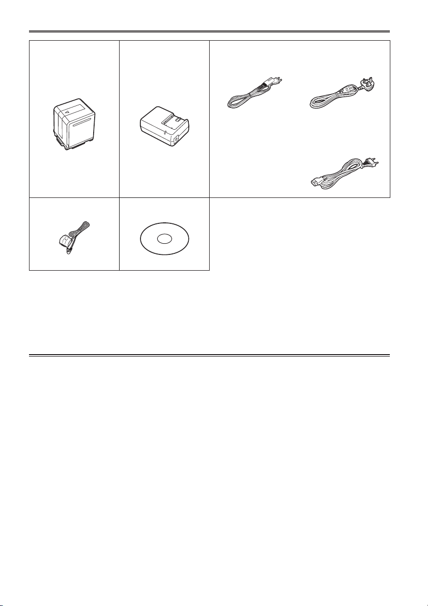
Accessories
∗
Battery
DC cable CD-ROM
∗
For part numbers for the battery, see “Optional accessories”.
Please consult a retailer when purchasing additional accessories.•
AC Adapter AC power supply cables
AG-HMR10P
AG-HMR10E
(For the U.K.)
AG-HMR10E
(For areas other than
the U.K.)
Optional accessories
Battery•
VW-VBG260 (7.2 V, 2640/2500 (typ./min.) mAh: equivalent to accessory battery)
Compact camera head for AG-HMR10•
AG-HCK10G (The camera head option cable is required for connecting to the AG-HMR10.)
Image sensor
1/4.1-inch, MOS type solid state image sensor × 3
Lens
Optical image stabilizer lens, motorized 12 × zoom
F1.8 to 2.8 (f = 4.0 mm to 48 mm)
(35 mm equivalent: 40.8 mm to 490 mm)
Filter diameter
43 mm
Color separation optical system
Prism system
Camera head option cable•
AG-C20003G (3 m (118-1/8 inches))
AG-C20020G (20 m (787-3/8 inches))
20
Page 21
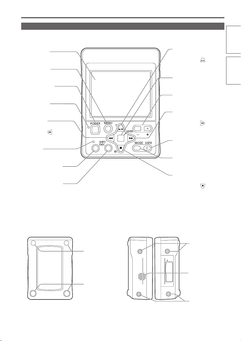
Description of parts
Operation panel, LCD and system parts
Front ■
LCD monitor
(Page 32)
MENU button
(Page 29)
POWER button
(Page 26)
POWER lamp
(Page 26)
REW button
(Pages 29, 44, 58)
Indicated by
operation descriptions.
Tally lamp
(Page 27)
REC/PAUSE button
(Pages 36, 37)
SHIFT/EXEC button
(Pages 41, 44)
in the
REC/
PAUSE
AUDIO MON/ADV
PLAY/STILL button
(Pages 29, 44, 58)
Indicated by
operation descriptions.
ENTER button
(Pages 29, 41, 44, 58)
AUDIO MON/ADV button
(Pages 44, 47, 68)
FF button
(Pages 29, 44, 58)
Indicated by
operation descriptions.
USER button
(Pages 41, 44)
MODE button
(Pages 28, 58)
STOP button
(Pages 29, 44, 58)
Indicated by
operation descriptions.
in the
in the
in the
Before use
of parts
Description
Rear ■ Side ■
Slide stoppers
Slide stoppers
Multipurpose
screw holes
(Page 15)
Built-in speaker
(Page 68)
Multipurpose
screw holes
(Page 15)
21
Page 22

Description of parts (continued)
Terminals and system parts
SD card cover
(Page 33)
Battery release button (Page 25)
CAMERA terminal (Page 37)
Battery compartment
(Page 25)
CAMERA terminal cover
SD Memory Card
access lamp
(Page 27)
SD Memory Card slot
(Page 33)
Card slot cover
(Page 33)
Card slot cover
open button
(Page 33)
22
HD-SDI OUT terminal
(Page 70)
HD-SDI IN terminal
(Page 36)
Use a double shielded cable equivalent to 5C-FB to connect to the HD-SDI IN terminal and HD-SDI •
OUT terminal.
Terminal covers
The terminals are inside the terminal cover.
Microphone terminal (Page 47, 69)
REMOTE jack
You can connect a remote control unit (optional) to
control the zoom and recording start/stop.
HDMI output terminal (Page 70)
Headphone jack (3.5 mm mini-jack)
(Pages 68, 69)
USB terminal (Pages 70, 71)
Page 23

Power sources
Charging
The battery does not come ready charged when the portable recorder is purchased. Charge the battery
before use.
It is recommended that you keep one extra battery as a spare.
Connect the power cable to the AC adapter.
1
Disconnect the DC cable.
(Battery cannot be charged if DC cable is
connected.)
Insert until fully in place.
Insert the battery.
2
Charging lamp [CHARGE]
Charging lamp ■
On: Charging in progress
Off: Charging complete
Flashing: See below
If charging lamp is flashing
■
Check that there is no dirt, dust, or other
substances attached to the connectors on the
battery or AC adapter, and ensure that the adapter
has been connected correctly.
If there is dirt or dust on the connectors, •
disconnect the power plug from the socket before
cleaning.
If the charging lamp continues to flash, there •
may be a fault with the battery or the AC adapter.
Please consult with the place of purchase.
of parts
Preparation Description
Align the battery with the
mark and insert fully.
Depending on the country and region, the actual
configuration of the power cable, plug, and
power outlet may differ from those shown in
these operating instructions.
(Continued on the next page)
23
Page 24

Power sources (continued)
Charging time and available recording time ■
(Approx.)
Battery
model
VW-VBG260
(included)
Voltage/
capacity
7.2 V/
2640/2500
(typ./min.)
mAh
Charging
time
Approx.
170
minutes
Maximum
continuous
recording time
SDI recording
(SDI mode):
Approx. 170
minutes
Recording
with
AG-HCK10G
connected
(CAM mode):
Approx. 70
minutes
The figures in the table above are guidelines •
for use in normal temperature conditions
(temperature 25 °C (77 °F), humidity 60 %).
Charging may take longer in higher or lower
temperatures.
Charging may take longer if the battery has not •
been in use for a long period of time.
Given here are the approximate continuous •
recording times when recording with no
connections to any external devices.
Available recording time may vary according to •
usage conditions.
Charging times are based on charging batteries •
from an empty state.
Remaining battery capacity displays
■
When using Panasonic-manufactured batteries
compatible with this product, the remaining battery
capacity is displayed in minutes.
90 min
Time remaining will be displayed after a brief pause.
The battery display will change•
→ → → →
battery capacity decreases.
will be displayed
as
in red when less than 3 minutes are remaining, and
will flash when the battery is empty.
Remaining battery capacity may not be displayed •
correctly when using in high or low temperatures,
or when the battery has not been used for a
long period of time. To ensure that remaining
battery capacity is displayed correctly, use the
battery completely from a fully-charged state,
and charge the battery again. (Remaining battery
capacity may still not be displayed correctly if the
battery has been used for long periods in high
or low temperatures, or if the battery has been
recharged a large number of times.)
The remaining battery capacity display is a •
guideline and may change according to usage
conditions.
The remaining battery capacity display will •
momentarily disappear when switching between
modes or when changing the LCD backlight
brightness since the capacity is recalculated at
these times.
Not displayed when using AC adapter.•
Keep metal objects (such as necklaces and •
hairpins) away from the battery.
Short-circuiting may occur across the
terminals, causing the battery to heat up,
and you may seriously burn yourself if you
touch the battery in this state.
The battery becomes hot while it is being used •
or charged. The portable recorder itself also
becomes hot during use.
The recordable time reduces if you repeatedly •
start and stop recording.
The battery takes longer to charge when it is •
warm.
The AC adapter can interfere with radio •
reception so keep radios at least 1 meter away
from it.
The AC adapter may make some noise when •
you are using it, but this is normal.
Battery cannot be recharged when the DC •
cable is connected to the AC adapter.
24
Page 25

Using the battery
Installation
Insert the battery into the battery compartment
of the portable recorder until it clicks into
place.
Panasonic VW-VBG260 battery may be used
with this product.
Using the AC adapter
Installation
Removal
Press the [POWER] button for 2 seconds or
1
longer to turn off the power. Check that the
POWER lamp goes off.
Remove the battery while pressing the
2
battery release button and sliding the
battery in the direction of the button.
Support the battery with your hand to ensure •
that it will not fall.
Battery release button
POWER lamp
Removal
Preparation
Connect the DC cable to the AC adapter.
1
Plug the AC power supply cable into the
2
power outlet.
Insert the DC cable plate into the battery
3
compartment of the portable recorder until it
clicks into place.
Press the [POWER] button for 2 seconds or
1
longer to turn off the power. Check that the
POWER lamp goes off.
Remove the DC cable plate while pressing
2
the battery release button and sliding the
DC cable plate in the direction of the button.
Disconnect the AC power supply cable from
3
the power outlet.
The battery cannot be charged while the DC •
cable is connected to the AC adapter.
The AC adapter is designed to be compatible •
with all power supply voltages (110 V to 240 V)
and power supply frequencies (50 Hz, 60 Hz)
around the world. Note that the shape of the
power outlet varies depending on the country.
Use a plug that is suitable for the country of use.
Contact a Panasonic authorized service center
for assistance in selecting a converter plug.
Disconnect the AC power supply cable from the •
power outlet when not using the portable recorder.
25
Page 26

Turning the power on/off
Press the [POWER] button for 2 seconds or longer.
The POWER lamp (green) illuminates and the •
power turns on.
If you press the [POWER] button for 2 seconds •
or longer when the power is on, the POWER
lamp flashes, the power turns off, and then the
lamp goes off.
Also, the POWER lamp flashes in the following
circumstances.
Recording error has occurred•
Camera cable is disconnected (when the AG-•
HCK10G camera head (optional) is connected)
Power-saving mode•
In line with the [POWER SAVE] setting in the
[OTHER FUNCTIONS] setup menu, the following
will apply if no designated operations∗ are
performed for approximately 5 minutes during
recording standby (when an SD Memory Card
has been inserted).
ON: The portable recorder turns off
automatically.
OFF: Does not switch off the portable recorder.
∗ For details on the designated operations, see
[POWER SAVE] in the setup menu (Page 92).
REC/
PAUSE
AUDIO MON/ADV
26
Page 27

Tally lamp
The tally lamp turns on during recording (red).
Also, the tally lamp flashes in the following
circumstances.
(flashes 4 times per second)
Recording error has occurred •
Battery has run out•
SD Memory Card is full •
System frequency has been changed•
(flashes once per second)
Remaining battery capacity is low •
Remaining memory of the SD Memory Card is low•
Setup menu has been initialized (Page 30) •
■
When the AG-HCK10G camera head
(optional) is connected
The tally lamp flashes in the following circumstances.
(flashes 4 times per second)
Cooling fan is not operating correctly•
Internal temperature of the camera is abnormally high•
Recording signal is corrupted•
Optical Image Stabilizer is not operating correctly•
Problem with the focus function•
Camera cable is disconnected•
SD Memory Card access lamp
The SD Memory Card access lamp lights as
follows depending on the access condition of the
SD Memory Card in the portable recorder.
Tally lamp
REC/
PAUSE
REC/
PAUSE
AUDIO MON/ADV
Preparation
REC mode, PB mode
■
Illuminated orange: Reading/writing possible
Flashing orange (fast): Verifying card/inspecting
Flashing orange (slow): Accessing card
Off: No card inserted/unformatted or incompatible
card inserted
PC mode
■
Flashing orange (slow): Accessing card
Off: A status other than accessing
card for possible defects
(recording, playing back
or loading)
SD Memory Card access lamp
Do not perform any of the following operations •
while the SD Memory Card access lamp is
flashing.
Performing these operations may damage the
SD Memory Card or its contents, or cause the
portable recorder to fail to operate correctly.
Removing the SD Memory Card ·
Switching off the power ·
Removing the battery ·
Connecting or disconnecting the USB ·
connection cable
Shaking or striking the recorder ·
27
Page 28

REC mode
PB mode
PC mode
Operation modes
The portable recorder has 3 operation modes: REC mode, PB mode and PC mode.
Press the [MODE] button to change the mode.
Press the
[POWER] button
for 2 seconds or
longer to turn on
the power.
or
While the power is off, connect the
AG-HCK10G camera head (optional) to the
portable recorder with the camera cable
(optional), and then press the [POWER] button
for 2 seconds or longer to turn on the power.
∗
Be sure to turn off the portable recorder’s
power before connecting or disconnecting
the camera head.
AUDIO MON/ADV
REC/
PAUSE
<SDI mode>
Used when connecting the portable
recorder to a device that has an
HD-SDI output, for recording onto
the portable recorder’s SD Memory
Card. This is suitable for operations
<CAM mode>
Used when operating the
AG-HCK10G camera head
(optional) to shoot with the portable
recorder and record onto the SD
Memory Card.
AUDIO MON/ADV
REC/
PAUSE
such as long backup recordings.
Before switching between SDI mode and CAM mode, be sure to turn off •
the power of the portable recorder. Connect or disconnect the camera
cable and then turn on the power again.
Press the [MODE] button.
Used for the playback of clips that are recorded
on the SD Memory Card.
Also, clip management operations, such as
deletion and protection, can be performed on the
thumbnail display screen.
Press the
[POWER]
button for 2
seconds or
longer
to turn off the
power.
28
Press the [MODE] button for 2 seconds or longer. “CHECK USB CABLE.” is
displayed. Connect the portable recorder to the computer with a USB cable.
Operation is not transferred to the PC mode when the AG-HCK10G •
camera head is connected.
When the AG-HCK10G is connected, turn
off the power, disconnect the camera cable, turn the power back on, and
then proceed with the operation.
Used when connecting to a computer to perform
operations such as clip saving and editing.
Page 29

Using the setup menus
Button operations in the setup menus ■
Displays the menu.
When the menu is displayed,
closes the menu.
Moves to the menu item above.
For some items, changes the
value.
Moves to the menu item on the
left. For some items, changes the
value.
Moves to the menu item below.
For some items, changes the value.
Using the menus
The menu items in gray cannot be changed.•
When the portable recorder is not recording
1
or playing back the clips, press the [MENU]
button.
The following is displayed on the LCD monitor.
REC mode (Example)
PB mode (Example)
Moves to the menu item to the
right. For some items, changes
the value.
Sets the selected item or value.
Press the [ENTER] button or to display
3
the setting items.
Example:
Press to move to the item that you
4
want to set.
Example:
Preparation
Press to move the yellow cursor to the
2
function that you want to set.
(Continued on the next page)
29
Page 30

Using the setup menus (continued)
Press the [ENTER] button or to set the
5
item.
Press
Example:
Repeat steps 4 to 5 to change any other
6
items.
Press the [MENU] button to complete the
setting and return to the normal screen.
Repeat steps 2 to 5 to change any other
7
settings.
Press the [MENU] button to complete the
setting and return to the normal screen.
to change the values.
Press • to return to the previous menu.
Initializing the setup menus
Perform the following operation during REC mode
to return the setup menus to their factory default
settings.
Press the [MENU] button.
1
Select [OTHER FUNCTIONS] → [MENU
2
INIT] → [YES], and then press the [ENTER]
button.
When “TURN POWER OFF” appears, turn the
power off by pressing the [POWER] button for 2
seconds or longer, then turn the power back on
again. The current setup menus return to their
factory default settings.
Even when the setup menus have been •
initialized, [TIME ZONE] will not revert to its
factory default setting.
The metadata is not initialized even when •
the setup menus have been initialized. (For
Initializing the metadata, see page 89.)
30
Page 31

Setting the date and time/Recharging the built-in battery/Adjusting the LCD monitor
Before recording with this portable recorder, first set the date and time and adjust the LCD monitor in the setup menus.
Setting the date and time
The [CLOCK SET] value in the setup menu is
recorded in the content (clip) and affects the thumbnail
playback sequence. Before recording, be sure to
check and set [CLOCK SET] and [TIME ZONE].
This example shows how to adjust the calendar to
17:20 on October 10, 2009.
Press the portable recorder’s [POWER]
1
button for 2 seconds or longer to turn on
the power. (Page 26)
Press the [MENU] button.
2
Using the setup menus (Page 29)
Select [OTHER FUNCTIONS] → [TIME ZONE],
3
and then press the [ENTER] button or
Press the [ENTER] button twice to display
4
the setting screen. Press
difference from Greenwich Mean Time, and
then press the [ENTER] button. (Page 92)
to set the time
.
Press to select [OCT].
6
Press to move the cursor to the next
7
item, and then press
Repeat steps 6 and 7 to set the remaining items.
8
to select [10].
Preparation
Press to return to the [OTHER FUNCTIONS]
5
setup menu, then select [CLOCK SET] →
[YES] and press the [ENTER] button.
The date can be set to any date between •
January 1, 2001 and December 31, 2039.
“--.--.----” is displayed for any date beyond •
December 31, 2039.
Time is displayed in the 24-hour format.•
When settings are complete, press the [ENTER]
9
button, select [YES] on the confirmation screen,
and then press the [ENTER] button again.
(Continued on the next page)
31
Page 32

Setting the date and time/Recharging the built-in battery/Adjusting the LCD monitor (continued)
Slight time errors may occur, so check that the •
time is correct before recording.
When using the recorder overseas, do not set •
the [CLOCK SET] time to the local time, but
instead enter the time difference from Greenwich
Mean Time in [TIME ZONE]. (Page 92)
Recharging the built-in battery
The recorder’s built-in battery saves the date and
time.
When “LOW INTERNAL BATTERY” is displayed
even when the date and time are set, it means
that the built-in battery is low. Recharge using the
following procedure.
Reset the date and time after the battery is fully
recharged.
Connect the AC adapter to the portable
1
recorder. (Page 25)
Leave off the power of the portable recorder.•
Leave the portable recorder like this for
2
about 4 hours.
The built-in battery recharges during this •
time.
Check the time code and menu operations •
after recharging.
If the date and time are still not memorized after
recharging, the built-in battery must be replaced.
Consult the place of purchase.
Adjusting the LCD monitor
Press the portable recorder’s [POWER]
1
button for 2 seconds or longer to turn on
the power. (Page 26)
Press the [MENU] button.
2
Using the setup menus (Page 29)
Select [DISPLAY SETUP] → [LCD SET] →
3
[YES], and then press the [ENTER] button.
LCD COLOR LEVEL:
LCD BRIGHTNESS: Adjusts the brightness of the
LCD CONTRAST: Adjusts the contrast of the
Be careful because if all the LCD monitor •
adjustment values are set to their lowest levels, it
becomes difficult to see the menu screens.
Press to set the item value, and then
5
press the [ENTER] button.
Adjusts the color density of
the screen.
screen.
screen.
Press to select an item, and then
4
press the [ENTER] button.
32
Press the [MENU] button to close the menu.
6
Page 33

SD Memory Cards
Inserting and removing SD Memory Cards
Open the SD card cover.
1
Slide the card slot cover open button to
2
the left to open the card slot cover.
Recording stops if the card slot cover is •
opened during recording.
Insert or remove the SD Memory Card.
3
Before removing the SD Memory Card, •
ensure that the SD Memory Card access
lamp is not flashing orange.
SD Memory Card access lamp
2
3
LOCK
32
To insert: Insert the card with the label facing up,
To remove: Press the center of the SD Memory
and push until it clicks firmly into place.
Card so that it pops out slightly, and
then pull the card straight outwards.
Always format SD Memory Cards that have •
been used in other devices when first using
them with this portable recorder. (Page 34)
If the system frequency of the portable •
recorder is changed, it will not be possible to
use an SD Memory Card. Before using a card,
format it with the current system frequency
settings.
When a card is formatted, all of its recorded •
data will be erased, and it will not be
subsequently possible to restore this data.
Save any valuable data onto your computer or
other storage media prior to formatting.
If “CHECK CARD” is displayed on the LCD •
monitor screen, remove the SD Memory Card
and insert it again.
Protecting SD Memory Cards
Move the write-protect switch on the SD Memory
Card to the “LOCK” position to prevent recorded
contents being accidentally erased from the card.
Write-protect
switch
LOCK
32
Preparation
Do not remove the SD Memory Card or switch off •
the power in the following circumstances. Doing
so may damage your SD Memory Card.
1) While the SD Memory Card access lamp is
still flashing orange after an SD Memory Card
has been inserted.
2) While the SD Memory Card access lamp is
flashing, such as during recording or during
recording finalization.
Close the card slot cover by pressing it up
4
with your finger.
Ensure that the cover firmly clicks into place.•
Close the SD card cover.
5
33
Page 34

SD Memory Cards (continued)
Repairing SD Memory Cards
Never remove the SD Memory Card or disconnect
the battery or DC cable while the SD Memory
Card access lamp is flashing, as doing so
may damage the SD Memory Card. If you do
accidentally remove the SD Memory Card while
the SD Memory Card access lamp is flashing,
or disconnect the battery or DC cable during
recording or the recording finalization process, a
repair verification screen is displayed the next time
the power is switched on, allowing errors to be
repaired.
Select [YES] to begin repairing. When repairing is
complete, “REPAIR FINISHED” will be displayed,
and the display will switch to the recording paused
screen.
Select [NO] to switch directly to the recording
paused screen without repairing.
Memory cards cannot be repaired with the •
portable recorder if [NO] is selected, but can still
be repaired by using the AVCCAM Restorer∗
content repair software.
An SD Memory Card on which an error occurred •
can be repaired by using either the recorder unit
that was used for the recording, or the AVCCAM
Restorer content repair software.
A repair confirmation message may be displayed •
after inserting an SD Memory Card which has no
error, but repair will not be performed even when
[YES] or [NO] is selected.
Repair may take up to 20 minutes or so •
depending on the places where the errors
occurred on the card.
Use a sufficiently charged battery or the AC
adapter.
If the repair operation has failed, “SYSTEM •
ERROR TURN POWER OFF” will be displayed.
In this case, please use the AVCCAM Restorer
content repair software.
Depending on the status of the data, it may not
be possible to restore all data completely. In this
case, it will no longer be possible to play back the
clips that were recorded before the power was
turned off.
Clips with a total recording time of less than 10 •
seconds may be impossible to repair.
Indexes attached during recording and metadata •
cannot be repaired.
∗
AVCCAM Restorer is provided on the CD-ROM
that is supplied with the portable recorder. Use
it with your computer. For details on using the
software, see the operating instructions (PDF file)
that are included on the supplied CD-ROM. The
AVCCAM Restorer can also be downloaded from
the following website.
https://eww.pavc.panasonic.co.jp/pro-av/
Formatting SD Memory Cards
Press the portable recorder’s [POWER] button for 2
1
seconds or longer to turn on the power. (Page 26)
Press the [MENU] button.
2
Using the setup menus (Page 29)
Select [CARD FUNCTIONS] → [CARD
3
FORMAT].
When the following screen appears, select [YES] •
and then press the [ENTER] button. Select [NO]
if you do not want to format the card.
Press the [MENU] button to close the menu.•
Select [YES] on the confirmation screen.
4
The SD Memory Card will be formatted.•
Press the [MENU] button to close the menu.
5
When an SD Memory Card is formatted, all •
of its recorded data will be erased, and it will
not be subsequently possible to restore this
data.
Save any valuable data onto your computer
or other storage media prior to formatting.
34
Page 35

SD Memory Card recording times
Total available recording times (approx.) when using SD/SDHC Memory Cards manufactured by •
Panasonic
1
∗
SD Memory Card
capacity
512 MB Approx. 2 min Approx. 3 min Approx. 4 min Approx. 10 min
1 GB Approx. 5 min Approx. 7 min Approx. 9 min Approx. 21 min
2 GB Approx. 10 min Approx. 15 min Approx. 20 min Approx. 45 min
4 GB Approx. 21 min Approx. 30 min Approx. 40 min Approx. 90 min
6 GB Approx. 33 min Approx. 45 min Approx. 60 min Approx. 135 min
8 GB Approx. 45 min Approx. 60 min Approx. 80 min Approx. 180 min
12 GB Approx. 65 min Approx. 90 min Approx. 120 min Approx. 270 min
16 GB Approx. 90 min Approx. 120 min Approx. 160 min Approx. 360 min
32 GB Approx. 180 min Approx. 240 min Approx. 320 min Approx. 720 min
∗1
Use an SD memory class of SD speed class 4 or above when recording on PH mode or HA mode.
PH
(Highest quality mode∗3/
1920 × 1080 pixels or
1280 × 720 pixels)
(High quality mode/
1920 × 1080 pixels)
Recording cannot be completed on SD Memory Cards of lower speed classes.
∗
2
Use an SD memory class of SD speed class 2 or above when recording in HG mode or HE mode.
∗3
This is the highest quality mode of this unit.
This unit uses the VBR recording system. “VBR” stands for Variable Bit Rate, and it refers to a system in which •
the bit rate (volume of data per given time period) varies automatically depending on the subject which is being
shot. This means that the recording times will be shorter when fast-moving subjects have been recorded.
Times displayed include time needed for processing, etc. – actual available recording times will be •
slightly shorter.
The unit is capable of continuous recording for a maximum of 12 hours.•
Mosaic-like noise may appear on the playback screen under the following shooting conditions:•
When there are complex patterns in the background ·
When a fast-moving subject has been recorded (and especially when HE has been set as the recording mode) ·
Repeatedly recording or deleting images over and over again may reduce the recording time on the SD •
Memory Card. In such cases, format the SD Memory Card using this unit. When a card is formatted, all
of its recorded data will be erased, and it will not be subsequently possible to restore this data. Save any
valuable data on your computer or other storage media or other storage media prior to formatting.
Recording mode
∗
1
HA
∗
2
HG
(Standard quality mode/
1920 × 1080 pixels)
∗
2
HE
(Long duration mode/
1440 × 1080 pixels)
Preparation
35
Page 36

Recording onto an SD Memory Card (REC mode)
The following 2 modes can be used to record onto an SD Memory Card.
SDI mode: When connected to an HD-SDI output device to perform input recording
CAM mode: When connected to the AG-HCK10G camera head (optional) to perform shooting and input
Performing HD-SDI input recording (SDI mode)
An external device that has an HD-SDI output terminal can be connected to record data such as video
signals, audio signals and time codes (S-LTC) onto the portable recorder.
recording
Camera-recorder
BNC cable (optional)
Press the [POWER] button for 2 seconds or
1
longer to turn on the power.
The SDI mode screen appears.
Indicates the mode
TC 12 : 34 : 56 . 00
112 min A PAUSE
PH 1080
60
ALC
C
1
H
C
2
H
Press the [MENU] button.
2
Using the setup menus (Page 29)
In the setup menus, set the following items
3
that are related to SDI mode.
[RECORDING SETUP] → •
[REC FORMAT] (Page 84)
• Set the recording format of the portable
recorder to the video format of the input
signal. If the formats are not the same,
recording is not possible and “SDI” flashes
on the LCD monitor screen.
SDI
–
120 min
HD-SDI IN
terminal
• The factory default setting for this unit is as
follows.
For AG-HMR10P: PH mode 1080/60i
For AG-HMR10E: PH mode 1080/50i
[RECORDING SETUP] → [AUTO REC] •
(Page 84)
Items in [TC/UB SETUP] (Page 86)•
Press the [REC/PAUSE] button to start
4
recording.
Recording is not possible when a menu •
screen is displayed. First close the menu
screen, and then press the [REC/PAUSE]
button.
If a camera-recorder is equipped with an •
external device control function, it can
perform operations for the portable recorder,
such as recording and recording standby. For
the compatible devices and portable recorder
settings related to HD-SDI connection, see
[AUTO REC] in the [RECORDING SETUP]
setup menu. (Page 84) See the operating
instructions of the camera-recorder for the
camera-recorder settings.
Press the [REC/PAUSE] button to finish
5
recording.
The portable recorder enters recording •
standby.
Portable recorder
recording
recording
36
Page 37

Shooting and recording with a camera (CAM mode)
When connected to the AG-HCK10G camera head (optional), you can shoot while operating the camera
function with the portable recorder.
AG-HCK10G
camera head
(optional)
Camera cable (optional)
CAMERA terminal
Portable recorder
Connect the portable recorder to the camera
1
head with the camera cable, and press the
[POWER] button for 2 seconds or longer to
turn on the power.
The CAM mode screen appears.
Indicates the mode
TC 12 : 34 : 56 . 00
112 min
PH 1080
60
ALC
24P 1/60
C
1
H
C
2
H
CAM
–
RECP
F
F5.6 Z00
120 min
ATW
0dB
AF 99
If you turn on the power before connecting •
the camera head, the portable recorder will
enter SDI mode and it cannot be changed to
CAM mode. If you connect or disconnect the
camera head while the portable recorder’s
power is on, it may cause a malfunction of
the portable recorder or camera head. Be
sure to turn off the portable recorder’s power
before connecting or disconnecting the
camera head.
If the camera head has an abnormality, such •
as a malfunction or broken cable, recording
is not possible. “SYSTEM ERROR TURN
POWER OFF” is displayed on the LCD
monitor screen and “CAM” flashes.
Press [MENU].
2
Using the setup menus (Page 29)
Select [RECORDING SETUP] → [REC
3
FORMAT], and then press the [ENTER]
button or
Press to select the recording format,
4
and then press the [ENTER] button.
.
The factory default setting for this unit is as •
follows.
For AG-HMR10P: PH mode 1080/60i
recording
For AG-HMR10E: PH mode 1080/50i
recording
Press the [REC/PAUSE] button to start
5
shooting.
Shooting is not possible when a menu •
screen is displayed. First close the menu
screen, and then press the [REC/PAUSE]
button.
The default setting for focus, iris and shutter •
speed adjustment is auto. To change the
settings, see page 50.
In CAM mode (when connected to AG-•
HCK10G camera head), no audio is output
from the built-in speaker.
Press the [REC/PAUSE] button to finish
6
shooting.
The portable recorder enters shooting •
standby.
(Continued on the next page)
Recording
37
Page 38

Recording onto an SD memory card (REC mode) (continued)
About recording onto SD Memory Cards ■
The images shot from when recording starts until it is stopped are recorded as one clip.•
The upper limit for the number of clips that can be recorded on a single SD Memory Card is 900. •
(However, note that this clip limit of 900 may be exceeded if recording is started immediately after turning
on the power.)
Recording is not possible in PB mode (Page 58) or PC mode (Page 71).•
SDI mode is not compatible with native recording.•
Operations during recording
■
Check that the video signal is being input before starting to record.•
Recording stops if the card slot cover is opened during recording.•
When recording is paused after a short period, a small amount of time may be required after pressing •
the [REC/PAUSE] button to stop recording before the writing to the SD Memory Card is terminated. This
means that operations are not accepted if the [REC/PAUSE] button is pressed again immediately.
The portable recorder reads information from the SD Memory Card immediately after the card is inserted. •
Press the [REC/PAUSE] button to start recording after “PAUSE” is displayed in the operation status
display. (Page 75)
If the input signal format is changed during recording, the recording will not be performed correctly.•
Do not stop the output of the external device or disconnect a cable while recording. If recording is •
performed again, the signal may not be recognized correctly.
Do not start recording while an irregular signal or a signal that is continuously corrupted is being input. •
The device may not operate correctly.
During recording, if the time information data recognition code (DBB1) in S-LTC or S-VITC that is •
superimposed on the HD-SDI input signal disappears, or the ON/OFF of the S-LTC or S-VITC is
changed, the video is corrupted at the time of the change.
38
Page 39

Setting the time code
Setting the time code
In the [TC/UB SETUP] setup menu, set the
following time code related items. (Page 86)
TC MODE•
(Only when [SYSTEM FREQ] is set to [59.9Hz])
TCG•
SDI REGEN•
TC PRESET•
When [SDI REGEN] is set to [ON],
the [TC MODE], [TCG] and [TC PRESET]
settings cannot be changed.
Specifying the time code (TC PRESET)
Set [TC PRESET] to record a value of your choice
as the initial time code setting to be used at the
start of recording.
Press the portable recorder’s [POWER]
1
button for 2 seconds or longer to turn on
the power.
Press the [MENU] button.
2
Using the setup menus (Page 29)
Select [TC/UB SETUP] → [TC PRESET].
3
When the screen below appears, set the
5
time code value.
Press
to select the time code value.
Press to move to the next digit, and then
press
again to select the value.
Example: To set 10 hours, 23 minutes, 46
6
seconds, frame 20, select the time code
value “10h23m46s20f.”
Press the [USER] button while setting the time
code to reset the time code to zero.
Press the [ENTER] button when you have
finished setting the time code.
Hour
Minute
Second
Frame
Recording
Press to move to [YES], and then press
4
the [ENTER] button.
Press to move to [YES], and then press
7
the [ENTER] button.
With this portable recorder, the time code value is
adjusted in accordance with the recording format
and frame rate. When shooting is performed with
the recording format set to 1080/24P or 720/24P,
recording is performed 4 frames at a time. For
this reason, if you change the recording format or
frame rate, it may result in discontinuity from the
last time code value of the previous recording.
(Only when [SYSTEM FREQ] is set to [59.9Hz])
39
Page 40

Setting the time code (continued)
Setting user information
The user information setting allows you to record
a memo, using up to 8 characters from a choice of
16 different character types.
User information is automatically saved in the
memory and retained after you turn off the power.
Press the portable recorder’s [POWER]
1
button for 2 seconds or longer to turn on
the power.
Press the [MENU] button.
2
Using the setup menus (Page 29)
Select [TC/UB SETUP] → [UB PRESET].
3
Press to move to [YES], and then press
4
the [ENTER] button.
Set the user information.
5
Press
to select the user information
characters.
You can use numbers from 0 to 9 and letters •
from A to F.
Press to move to the next digit, and press
again to select the character.
Press the [USER] button while setting the user
information to reset the user information to zero.
Press the [ENTER] button when you have
6
finished setting the user information.
40
Press to move to [YES], and then press
7
the [ENTER] button.
Page 41

Using the [USER] button
You can assign one of eleven functions to the
[USER] button. Using the [USER] button allows
you to easily switch the portable recorder function.
Select [USER] from the [OTHER
1
FUNCTIONS] setup menu.
Using the setup menus (Page 29)
Select the function∗ that you want to assign
2
to the [USER] button, and then press the
[ENTER] button.
∗
The functions that can be assigned are shown
in the table below.
Press the [MENU] button to close the menu.
3
Press the [USER] button.
4
The function that you assigned to the [USER]
button operates.
Press the [SHIFT/EXEC]
button during REC mode
to display the assigned
USER ASSIGN:COUNTER
Screen display
INT
REC CHECK
SPOTLIGHT
BACKLIGHT
ATW LOCK
LCD DTL
LCD REVERSE
INDEX
SHOT MARK
LAST CLIP
COUNTER
∗1
If [SHOT MARK] is assigned to the [USER] button,
it can be used during the thumbnail display.
∗2
If [COUNTER] is assigned to the [USER] button,
it can be used during clip playback.
[COUNTER] is assigned as the factory default.•
If you press the [USER] button to operate a •
function and then turn off the power, the function is
canceled. (However, [LCD DTL] is not canceled.)
∗
∗
2
function on the LCD
monitor screen.
1
Usable modes
SDI CAM
○○
○
○
○
○
○○
○○
○○
○○
○○
○○
INH (Disable operation) ■
When INH is assigned, there is no operation
when the [USER] button is pressed.
REC CHECK (Check the recording) ■
When the [USER] button is pressed during
shooting standby, about 2 seconds of the video
and audio that were recorded immediately
before are played back. After playback, the
portable recorder returns to shooting standby.
• Only the [POWER] button, [REC/PAUSE]
button and [AUDIO MON/ADV] buttons are
operable during REC CHECK.
• The REC CHECK images are also recorded
when a device is connected to the portable
recorder and backup images are being
recorded.
• The [USER] button will not work even if it is
pressed when any of the following operations
have been performed upon completion of
recording/shooting.
• Operation is switched to the PB mode
• Recording format is changed
• Portable recorder’s power is turned off and
then turned back on
• SD Memory Card is ejected
SPOTLIGHT
■
Performs auto iris control for the spotlight.
“SPOT” is displayed on the screen.
Press the [USER] button again to cancel.
When [MANUAL] is selected from the setup
menu [CAMERA SETUP] → [IRIS], even pressing
the [USER] button will not cause this to operate.
BACKLIGHT (Backlight compensation) ■
When the shooting subject is lit from behind,
performs backlight compensation auto iris control
so that the subject does not come out dark.
“BACK” is displayed on the screen.
Press the [USER] button again to cancel the
backlight compensation.
When [MANUAL] is selected from the setup
menu [CAMERA SETUP] → [IRIS], even pressing
the [USER] button will not cause this to operate.
ATW LOCK ■
Fixes the white balance value when the [USER]
button is pressed during ATW.
“LOCK” is displayed on the screen.
Press the [USER] button again to perform the
ATW function.
(Continued on the next page)
Recording
41
Page 42

Using the [USER] button (continued)
LCD DTL (Emphasizing outlines) ■
Emphasizing the outlines of the images you
see on the LCD makes it easier to focus.
Emphasizing the outlines does not affect the
images you record.
When this is set, the “LCD DTL ON” message
is displayed in the middle of the screen. (CAM
mode only)
Press the [USER] button again to cancel.
• This function is not canceled even when the
power is turned off.
• When the [USER] button is used to switch
between performing and canceling this
function, the [LCD DTL] setting in the
[DISPLAY SETUP] setup menu is also
switched.
LCD REVERSE (Reversing image display)
■
While the [USER] button is pressed, viewing
angles and video images can be verified by
reversing the images displayed on the LCD
monitor horizontally and vertically.
The recorded images are not affected when the
images are reversed on the screen.
• The normal display is shown when the [USER]
button is not pressed.
INDEX (Index function)
■
This function allows you to add an index at a
certain point of a clip during recording.
Press the [USER] button during recording or
shooting. “INDEX” is displayed on the screen
and an index signal is recorded at that point.
• To add an index during playback, select
[INDEX] → [YES] from the [OPERATION]
setup menu. (Pages 64, 91)
• If an index cannot be added, “INVALID” is
displayed.
• Added indexes can be deleted in PB mode.
(Page 64)
• Up to 100 indexes can be recorded for one
clip.
• When the number of indexes exceeds 100,
“INVALID” is displayed, and no further indexes
can be added even when the steps for adding
indexes are taken.
• When repeatedly adding indexes, leave a gap
of at least one second between adding one
index and the next. If indexes are added with
a gap of less than one second between them,
only the first operation will be valid.
SHOT MARK (Shot mark function)
■
The marks added to clip thumbnails are called
shot marks. In the thumbnail screen, only clips
with a shot mark can be selected for display or
playback.
Press the [USER] button during recording or
shooting. “MARK ON” is displayed on the LCD
monitor screen and a shot mark is set for the
thumbnail of the clip being recorded. Press the
button again to cancel.
You can also set or cancel shot marks in the
thumbnail screen of PB mode. However, note
that you cannot set or cancel shot marks during
playback.
• If shot marks cannot be set or canceled,
“INVALID” is displayed.
LAST CLIP (Last clip delete function)
■
Deletes the last clip that was recorded or shot.
When the [USER] button is pressed during
recording or shooting standby, the “DELETE
LAST CLIP?” message is displayed on the LCD
monitor screen. Select [YES] to delete the last
clip that was recorded or shot.
If you do not want to delete the clip, select [NO].
• If one of the following operations is performed
after finishing recording or shooting, the last
clip cannot be deleted even if the [USER]
button is pressed.
• Mode is changed to PB mode
• Recording format is changed
• Portable recorder’s power is turned off and
back on again
• SD Memory Card is removed
42
Page 43

COUNTER (Counter function) ■
You can display a counter that indicates how
much time has elapsed during recording or
shooting.
Each time you press the [USER] button, the
display changes as follows.
0 : 00 . 00
Counter value display
Press the [USER] button for 1 second or ·
longer to reset the counter value to zero.
Not displayed during clip playback. ·
CLIP 0 : 00 . 00
Displayed when [REC COUNTER] → [CLIP]
in the [DISPLAY SETUP] setup menu is
selected.
Values are automatically reset when
recording or shooting is started, and counter
values are displayed for each clip.
TC 12 : 34 : 56 . 01
Time code display
When [SYSTEM FREQ] is set to [59.9Hz]
Frame digits are displayed in 24 frames
when 24P is set. Frame digits are
displayed in 30 frames when any other
format is set.
When [SYSTEM FREQ] is set to [50Hz]
Frame digits are displayed in 25 frames.
Recording
UB 12 34 56 78
User information display
No display
Data is not displayed.
Even during clip playback, the [USER] button •
can be used to change the counter.
The counter that is displayed during playback
is CLIP 0 : 00 . 00, regardless of the [REC
COUNTER] setting in the [DISPLAY SETUP]
setup menu.
If the external input signal and time code or •
user information match when [SDI REGEN]
→ [ON] in the [TC/UB SETUP] setup menu is
selected, the time code or user information is
displayed in reverse.
43
Page 44

Useful recording and shooting functions
If you press designated buttons while pressing down the [SHIFT/EXEC] button, you can use useful
recording and shooting functions.
Operation is not possible when a menu screen is displayed. First close the menu screen, and then •
perform the operation.
If the [SHIFT/EXEC] button is pressed, designated buttons and function guidance will be displayed on •
the LCD monitor screen.
AUDIO MON/ADV
AUDIO MON/ADV
REC/
PAUSE
Buttons pressed at
the same time as the
[SHIFT/EXEC] button
[AUDIO MON/ADV – ]
button
[AUDIO MON/ADV + ]
button
[ENTER] button
(Press and hold)
(Press and hold)
[USER] button LCD OFF Turn on or off the LCD monitor (Page 47)
Screen
display
MIC LEV – Lower the audio input and output level (Page 47)
MIC LEV + Raise the audio input and output level (Page 47)
KEY LOCK
FA Display the focus assist (Page 46) –
WFM Display the wave form monitor (Page 46)
ONE PUSH
AF
AWB Adjust the white balance/black balance (Page 45) –
Lock the button operations or cancel the setting
(Page 46)
Temporarily switch to auto focus mode (Page 46) –
Function
Usable modes
SDI CAM
○○
○○
○○
○
○○
○
○
○○
44
Page 45

46Useful recording and shooting functions (continued)
White balance and black balance adjustment
White balance
In order to reproduce the white accurately, adjust
the ratio between the three RGB primary colors.
If the white balance is not adjusted properly,
not only will the white be reproduced poorly, but
the color tones of the entire screen will also be
downgraded. When you are shooting in manual
mode, readjust the white balance whenever
lighting conditions change. You can save the white
balance adjustment values in W.SET. You can also
use the preset values. Use the settings that suit the
shooting conditions.
Black balance
In order to reproduce the black accurately, adjust
the ratio between the three RGB primary colors. If
the black balance is not adjusted properly, not only
will the black be reproduced poorly, but the color
tones of the entire screen will also be downgraded.
It is not normally necessary to adjust the black
balance, but adjustment is necessary if using the
portable recorder when the ambient temperature
has changed greatly.
Adjusting the white balance and black balance
Place a white pattern in a location with the
1
same lighting conditions and light source
as the subject and fill the whole screen with
white.
Something white (a white cloth or wall) near •
the subject can be used instead.
Do not include bright spotlights in your shot.•
Mode Operation Adjustment
Recording
W.SET
ATW
P3.2K
P5.6K
When the adjustment starts, the following •
messages appear on the screen.
Example of message during adjustment
AWB ABB ACTIVE
Example of message after adjustment
AWB ABB OK
An error message appears on the LCD monitor •
screen when automatic adjustment of the white
balance is not possible.
Message when adjustment cannot be done
AWB NG
Adjustment is not possible at shutter speeds of
1/2 – 1/15.
Other than
recording
Recording
Other than
recording
White balance
adjustment is performed.
Black balance adjustment
is performed after white
balance adjustment.
Adjustment is not
performed.
Black balance
adjustment is performed.
Recording
Select the white balance mode.
2
Setting the white balance (Page 53)•
While pressing the [SHIFT/EXEC] button,
3
press
for 1 second or longer.
In accordance with the mode that you •
selected in step
black balance adjustment starts as in the
following table.
2, the white balance and
45
Page 46

Using focus assist (FA)
The center of the screen can be enlarged to make
it easier to focus.
While pressing the [SHIFT/EXEC] button,
1
press
.
The center of the screen will be enlarged by a
factor of about 4 in the vertical direction and
about 6 in the horizontal direction.
“EXPANDED” is displayed on the screen during
the expanded display.
The center of the angle of view is shifted slightly •
from the center of the LCD monitor screen.
This function cannot be used while the digital •
zoom function is in use.
Press the button again to return to the •
original screen.
The setting is canceled when the power is turned off.•
Select [FOCUS BAR] → [ON] in the •
[DISPLAY SETUP] setup menu to display the
focus assist bar.
The length of the bar indicates whether the
image is in focus.
The bar extends to the far right when the
image is in focus.
Out of focus The bar extends to the
right when the image
is in focus.
Wave form monitor (WFM)
During recording or shooting, an image wave form
can be displayed on the LCD monitor screen.
While pressing the [SHIFT/EXEC] button,
1
press
Each time
as follows:
WAVE → VECTOR → OFF → WAVE
WAVE: Sets the wave form display.
VECTOR: Sets the vector display.
OFF:
.
is pressed, the setting changes
Does not display the wave form or vector.
Does not display while the focus assist •
function is operating.
The wave form or the vector cannot be recorded.•
The setting is canceled when the power is •
turned off.
Temporarily switching to auto focus mode (ONE PUSH AF)
Even during manual focus (Page 50), you can
temporarily switch to auto focus mode to focus
automatically.
While pressing the [SHIFT/EXEC] button,
1
press
.
While the [SHIFT/EXEC] button and
pressed, the mode switches to auto focus mode
and automatic focusing is performed.
Auto focus may not work properly if there is •
flickering. Select a shutter speed suited to
the ambient light. (Page 51)
If the auto focus mode is set with any •
format except 60i and 60P (or 50i and 50P),
controlling the focus will take slightly longer.
are
Preventing accidental operation (KEY LOCK)
The operation buttons can be temporarily disabled
to prevent accidental operation.
While pressing the [SHIFT/EXEC] button,
1
press the [ENTER] button for 2 seconds or
longer.
All button operations are disabled.•
Press the same buttons again for 2 seconds •
or longer to unlock.
The lock setting is canceled when the power •
is turned off.
While the operations are locked, •
is displayed on the LCD monitor screen.
When the remote control (optional) is connected
to the REMOTE jack of the portable recorder,
recording and zoom operations with the remote
control are available even during key lock.
(yellow)
Page 47

Turning off the LCD monitor screen (LCD OFF)
The LCD monitor screen can be turned off.
While pressing the [SHIFT/EXEC] button,
1
press the [USER] button.
Press the same buttons again to cancel the •
setting.
The setting is canceled when the power is •
turned off.
When the LCD monitor screen is off, in •
addition to the buttons for turning the screen
back on, the [POWER] button and [REC/
PAUSE] button can also be operated.
Adjusting the recording level of the input audio (MIC LEV)
The recording level of the input audio from the
microphone connector can be adjusted.
While pressing the [SHIFT/EXEC] button,
1
press the [AUDIO MON/ADV + ] or
[AUDIO MON/ADV - ] button.
AUDIO MON/ADV + : Raises the input level.
AUDIO MON/ADV - : Lowers the input level.
While adjusting, refer to the level display for
microphone input adjustment on the LCD
monitor screen.
<When the AG-HCK10G camera head is connected>
<When the microphone connector is connected>
Check the recording volume level prior to •
shooting.
The recording level is set approximately 8 dB •
higher than Panasonic broadcasting camerarecorders (AJ series products).
When an external microphone is connected •
to the microphone terminal, the input audio
switches automatically to the external
microphone.
When an external microphone is not •
connected to the microphone terminal, the
input audio is selected as follows.
CAM mode: Built-in microphone of the AG-
SDI mode: HD-SDI embedded audio signal
HCK10G camera head (optional)
Color bar
By selecting [INT SG] → [ON] in the [RECORDING
SETUP] setup menu, you can display a color bar
during REC mode, which is useful when adjusting
the image quality of a television or external
monitor.
While the color bar is displayed, a test tone of •
1 kHz∗ will be output from the headphone
terminal and built-in speaker. (However, in
CAM mode there is no output from the built-in
speaker.)
∗
When [SYSTEM FREQ] is set to [50Hz],
a test tone of 997 Hz is output.
The color bar can be recorded by pressing the •
[REC/PAUSE] button.
The function is not canceled even when •
the power is turned off. To cancel the color
bar display, select [INT SG] → [OFF] in the
[RECORDING SETUP] setup menu.
To output the color bar from the SDI OUT
terminal, select [SDI EE SEL] → [NORMAL] in
the setup menu [AV OUT SETUP].
Time stamp function
The date and time of recording can be recorded on
the video images.
Select [TIME STAMP] → [ON] in the [RECORDING
SETUP] setup menu.
When [TIME STAMP] is [ON],
the LCD monitor.
• itself is not recorded on the video images.
R
The size and position of the date and time •
characters recorded on the image will vary
depending on the recording format.
The size and position of the date and time •
characters recorded on the image in external
output displays may vary from the displays on the
LCD monitor.
The recorded date and time display will follow the •
[DATE/TIME] setting in [DISPLAY SETUP].
When [DATE/TIME] is set to [OFF], the date and
time of recording are not recorded even if [TIME
STAMP] is set to [ON].
To avoid date and time displays overlapping •
when clips with time stamps recorded are played
with this portable recorder, select [DATE/TIME]
→ [OFF] in the [DISPLAY SETUP] setup menu.
R
is displayed on
Recording
47
Page 48

Operating the camera head
The operation buttons on this portable recorder can be used to operate the camera function of the AGHCK10G camera head (optional).
Operation is not possible when a menu screen is displayed. First close the menu screen, and then •
perform the operation.
AUDIO MON/ADV
REC/
PAUSE
REC/
PAUSE
AUDIO MON/ADV
Using the zoom function
The AG-HCK10G camera head (optional) has a
12 x optical zoom function.
Press or .
1
: Zoom in
: Zoom out
The current zoom range
(Z00 to Z99) is displayed
on the LCD monitor
screen.
Z99
Press and hold the button to zoom at low •
speed, and press it 2 times in a row, then
subsequently press and hold to zoom at high
speed.
Digital zoom function
The digital zoom function can be used when
[D.ZOOM] in the [CAMERA SETUP] setup menu is
set to something other than [OFF]. (Page 83)
The higher the zoom ratio setting, the poorer the •
image quality.
For all settings other than [OFF] (x 1), the current •
zoom ratio will be displayed on the LCD monitor
screen.
The digital zoom function can only be used with •
the 1080/60i and 720/60P (or 1080/50i and
720/50P) recording formats.
The digital zoom setting cannot be adjusted •
during shooting.
48
Page 49

PRE REC
Record video and audio from three seconds before
the time of the operation to start recording.
Operation to start
recording
Actual recording
time
PRE REC time
Select [TCG] → [FREE RUN] in the [TC/UB
1
SETUP] setup menu.
Using the setup menus (Page 29)
Select [PREREC MODE] → [ON] in the
2
[RECORDING SETUP] setup menu.
“P-PAUSE” will be displayed on the screen.
When recording is started while “P-PAUSE” •
is not displayed on the screen, normal
recording is performed.
When [REC RUN] is set in [TCG] in the [TC/•
UB SETUP] setup menu, the setting will be
automatically changed to [FREE RUN].
Press the [REC/PAUSE] button.
3
Video and audio from approximately 3 seconds
previously will be recorded.
Recording of the previous 3 seconds of video •
and audio may not be possible if recording is
started in the following cases.
Immediately after switching from PB mode ·
to CAM mode
Immediately after turning the power on ·
Immediately after setting [PREREC ·
MODE] to [ON]
Immediately after setting TC or UB ·
The thumbnail for clips recorded using the •
PREREC function will display the image from
when the [REC/PAUSE] button was pressed.
When clips that were recorded using the •
PREREC function are played back, the
images pause momentarily during clip
changeovers. (Page 97)
An index is not added to the head of the clips •
which were recorded using the PREREC
function.
Operation to stop
recording
(Time)
Optical Image Stabilizer
Use the Optical Image Stabilizer (OIS) to reduce
the effects of camera head shake when shooting
by hand.
Select [O.I.S.] → [ON] in the [CAMERA
1
SETUP] setup menu.
Using the setup menus (Page 29)
When the [O.I.S.] is [ON],
the LCD monitor screen.
When the camera head is fixed, such as when
using a tripod, set the [O.I.S.] to [OFF] for more
natural images.
This function will not be as effective when •
the vibration is severe or when tracking a
moving subject.
is displayed on
Recording
49
Page 50

Operating the camera head (continued)
Performing manual adjustments (CAMERA FUNCTIONS)
The focus, iris, shutter speed and white balance can be manually adjusted.
Enable manual adjustment by setting the items in the [CAMERA SETUP] setup menu. (See table
1
below)
Press the [ENTER] button to select the function.
2
F
Press to adjust.
3
■
Function and menu settings
Display on LCD
monitor screen
F Focus adjustment (Page 50) FOCUS MANUAL
I Aperture and brightness adjustments (Page 50) IRIS MANUAL
S Shutter speed adjustment (Page 51) IRIS
W White balance setting (Page 53)
∗
AUTO2: Automatically adjusts the iris and gain according to the light source for the optimum brightness.
Each time you press the [ENTER] button, the functions that can be manually
adjusted are displayed in order on the LCD monitor.
F → I → S → W
Function
CAMERA SETUP menu
Item Setting
AUTO2∗ or
MANUAL
--
F
Adjusting the focus (manual focus)
Select [FOCUS] → [MANUAL] in the
1
[CAMERA SETUP] setup menu.
Using the setup menus (Page 29)
Press the [ENTER] button to display
2
F on the LCD monitor screen.
F
Press or to adjust the focus.
3
: Moves the focus further away
: Moves the focus closer
MF 19
Even in auto focus mode, it is possible to •
move the focus temporarily.
The current value is
displayed on the LCD
monitor screen.
50
I
Adjusting the aperture and brightness
Select [IRIS] → [MANUAL] in the [CAMERA
1
SETUP] setup menu.
Using the setup menus (Page 29)
Press the [ENTER] button to display
2
I on the LCD monitor screen.
I
Press or to adjust the lens aperture
3
and brightness.
: Adjusts iris and gain for more brightness
: Adjusts iris and gain for less brightness
The current F value, as
well as gain and shutter
10dB
F2.4
values, are displayed on
the LCD monitor screen.
Page 51

S
Adjusting the shutter speed
Select [IRIS] → [AUTO2] or [MANUAL] in the
1
[CAMERA SETUP] setup menu.
Using the setup menus (Page 29)
Press the [ENTER] button to display
2
S on the LCD monitor.
S
Press or to adjust the shutter speed.
3
: Increases the shutter speed
: Reduces the shutter speed
The current value is
displayed on the LCD
monitor screen.
1/60
Remember that the faster the shutter speed, •
the lower the sensitivity.
If [IRIS] → [AUTO2] in the [CAMERA •
SETUP] setup menu is selected, the aperture
will open wider with higher shutter speeds
and thereby reduce focal depth.
It will take longer to focus when the •
shutter speed has been reduced, so it is
recommended that the camera head be
secured to a tripod, etc. for use.
When [OTHER DISPLAY] → [ON] in the •
[DISPLAY SETUP] setup menu is selected,
the currently set shutter speed is displayed
on the LCD monitor screen.
With artificial lighting and especially •
fluorescent lights and mercury-vapor lamps,
the luminance changes in synchronization
with the power line frequency. When this
frequency is 50 Hz, mutual interference
will occur between the portable recorder’s
vertical sync frequency (approx. 60 Hz)
and the lighting frequency (50 Hz). This
means that the white balance may change
periodically. Before shooting in areas with
artificial lighting or adjusting the white
balance, set the shutter speed with reference
to the following tables.
When [SYSTEM FREQ] is set to [59.9Hz]
Frame rate
60i 1/100 1/60
30P 1/50 1/60
24P 1/50 1/60
When [SYSTEM FREQ] is set to [50Hz]
Frame rate
50i 1/50 1/60
25P 1/50 1/60
Shutter speed
50 Hz 60 Hz
Shutter speed
50 Hz 60 Hz
Recording
(Continued on the next page)
51
Page 52

Operating the camera head (continued)
Range of shutter speed variations ■
When [SYSTEM FREQ] is set to [59.9Hz]
With the 1080/60i or 720/60P formats
SYNCRO SCAN 1/151/2 1/30 1/601/4 1/8
1/2000 1/1000 1/500 1/250 1/120 1/100
With the 1080/30P or 720/30P formats
SYNCRO SCAN 1/151/2 1/30 1/501/4 1/8
1/2000 1/1000 1/500 1/250 1/120 1/60
With the 1080/24P or 720/24P formats
SYNCRO SCAN 1/121/2 1/24 1/501/3 1/6
1/2000 1/1000 1/500 1/250 1/120 1/60
When [SYSTEM FREQ] is set to [50Hz]
SYNCRO SCAN 1/121/2 1/25 1/501/3 1/6
1/2000 1/1000 1/500 1/250 1/120 1/60
(Standard)
(Standard)
(Standard)
(Standard)
Synchro scan ■
Set the shutter speed of the synchro scan (used
when shooting a television or computer monitor) in
[SYNCRO SCAN] in the [CAMERA SETUP] setup
menu. (Page 82)
Adjust the shutter speed to match the frequency •
of the television or computer monitor to minimize
the horizontal noise that appears when shooting
such subjects.
By switching to progressive mode you can also •
shoot PAL system television screens.
If a [SYNCRO SCAN] selection item is grayed •
out, it cannot be used with the current recording
format. This function will only operate with the
preset values for each recording format.
The preset values for the recording formats are
as follows.
52
When [SYSTEM FREQ] is set to [59.9Hz]
60i/60P mode: 1/60.0-1/250.0
30P mode: 1/30.0-1/250.0
24P mode: 1/24.0-1/250.0
When [SYSTEM FREQ] is set to [50Hz]
50i/50P mode: 1/50.0-1/250.0
25P mode: 1/25.0-1/250.0
You can change the progressive mode in [REC •
FORMAT] in the [RECORDING SETUP] setup
menu. (Page 54)
Page 53

W
Setting the white balance
Press the [ENTER] button to display
1
W on the LCD monitor.
W
Press or to select the mode.
2
Each time you press
or , the modes are
W.SET
Mode Description
W.SET
ATW
P3.2K
P5.6K
Select to adjust the white balance
and black balance to suit the shooting
conditions.
If the ATW (Auto Tracking White)
function is used to automatically
analyze the shooting environment, the
white balance is constantly adjusted to
the optimum value.
Uses the preset values. This is useful
if you do not have time to adjust the
white balance.
Guide to preset values
P3.2K (3200 K): halogen light
P5.6K (5600 K): outdoors
displayed in order on the
LCD monitor screen.
Depending on the environment, there may be •
some error in the adjustment.
Adjust the white balance yourself if you need •
a more precise white balance. (For adjusting
the white balance and black balance, see page
45.)
Recording
53
Page 54

Shooting in progressive mode
Select [REC FORMAT] → [PH1080/30P]
or [PH1080/24P] (or [PH1080/25P]) in the
[RECORDING SETUP] setup menu to enable
shooting in progressive mode. (Page 84)
30P mode:
(When [SYSTEM FREQ] is set to [59.9Hz])
Shoot 30 frames a second in the progressive
mode. For output and recording, the 30-frameper-second video signal is converted to a
60-field-per-second interlace.
This mode gives you high quality images.
ABCDEFGH I J
30 P
Ao AeBoBeCo CeDo DeEoEe Fo FeGoGeHoHe Io Ie Jo Je
60 i
24P mode:
(When [SYSTEM FREQ] is set to [59.9Hz])
Shoot 24 frames a second in the progressive
mode. The video signal will be recorded natively.
However, the external output signal is converted
to a 2:3 format, 60 fps interlaced signal.
24 P
A B C D E F G H
Ao AeBoBeBo CeCoDe DoDe Eo Ee FoFe FoGeGoHeHoHe
60 i
Note the following when shooting in
progressive mode.
Set the shutter speed to 1/50 for best results.•
There may be a slight delay to the start •
of recording when you use the 24P mode
because 4 frames are recorded at a time.
25P mode:
(When [SYSTEM FREQ] is set to [50Hz])
Shoot 25 frames a second in the progressive
mode. For output and recording, the 25-frameper-second video signal is converted to 50-fieldper-second interlace.
This mode gives you high quality images.
ABCDEFGH I J
25 P
Ao AeBoBeCo CeDo DeEoEe Fo FeGoGeHoHe Io Ie Jo Je
50 i
54
Page 55

Clip metadata
You can add the video and audio systems, name
of the videographer, shooting location, text memos
and other information to the video data you have
recorded on the SD Memory Card. This data is
called the clip metadata.
(Display method: Page 65)
There are 2 kinds of clip metadata: the data that
is recorded automatically during shooting, and the
data in the metadata upload file created on the SD
Memory Card which is loaded onto the portable
recorder.
(Loading method for clip metadata: Page 56)
Description of clip metadata
You can set the underlined items below by loading
the metadata upload file on the SD Memory
Card. All other items are set automatically during
recording.
GLOBAL CLIP ID:
This indicates the global clip ID that shows the
shooting status of the clip.
USER CLIP NAME:
This indicates the name of the clip that the user
VIDEO & AUDIO:
This indicates the recorded image’s FRAME
ACCESS:
This indicates the CREATOR (name of the
DEVICE:
This indicates the MANUFACTURER
SHOOT:
This indicates the SHOOTER (name of the
LOCATION:
This indicates ALTITUDE, LONGITUDE,
∗
1
has set.
RATE, RESOLUTION, PULL DOWN system and
AUDIO.
person recording), CREATION DATE (recording
date), LAST UPDATE DATE (date on which
the data was last updated) and LAST UPDATE
PERSON (the person who last updated the
data).
(manufacturer of the equipment), SERIAL NO.
(serial number of the equipment) and MODEL
NAME (equipment model name: AG-HMR10).
videographer) and the PLACE NAME (name of
location).
LATITUDE, and SOURCE (information source).
2
SCENARIO:
∗
This indicates the PROGRAM NAME,
SCENE NO. and TAKE NO.
NEWS 1:
This indicates the REPORTER
(name of the reporter) and PURPOSE
(purpose of data collection).
NEWS 2:
This indicates the OBJECT (target of data
collection).
∗
3
MEMO:
This indicates the PERSON (name of the person
who recorded the text memo) and TEXT
(contents of memo).
∗
1
If there is no information in the metadata upload
file, consecutive five-digit numbers will be
applied to the clips in the order that they were
recorded, with the first clip to be recorded given
the number 0. The USER CLIP NAME recording
method is selectable. See page 57 for details.
∗
2
When SCENARIO is to be input, you must input
PROGRAM NAME. You cannot input SCENE
NO. and TAKE NO. only.
∗
3
When MEMO is to be input, you must input
TEXT. You cannot input PERSON only.
Only printable ASCII characters can be •
displayed by this portable recorder.
Because there is a limit to the number of •
characters that can be displayed by this
portable recorder, not all the data can be
displayed. (This does not mean that the data
which is not displayed has been deleted.)
Use the AVCCAM Viewer or other program to
check all the data.
Metadata can be created with AVCCAM •
Viewer. (Page 100)
Recording
55
Page 56

Clip metadata (continued)
Uploading the metadata (META DATA)
You can perform any of the following operations.
If necessary, perform preparations prior to the
operation.
Loading the metadata
Insert the SD Memory Card on which the •
metadata is recorded into the portable recorder.
(For a description of the clip metadata,
see page 55.)
Selecting whether to record the metadata
on the SD Memory Card
Initializing the metadata inside the portable
recorder
Displaying the metadata inside the portable
recorder
Press the [MODE] button to select REC
1
mode.
Operation modes (Page 28)
Press the [MENU] button.
2
Using the setup menus (Page 29)
Press to select [META DATA], and
3
then press the [ENTER] button or
.
CARD READ:
The metadata that is set on the SD Memory
Card is loaded onto the portable recorder.
Press the [ENTER] button to select the
metadata to be loaded, select whether or not
the metadata is to be loaded (YES/NO), and
then press the [ENTER] button.
Up to 10 items of metadata on the SD ·
Memory Card can be displayed, starting
from the most recent creation date.
If characters other than single-byte ·
alphanumeric characters are used in the
metadata file name that is loaded, they are
displayed as “∗”.
RECORD:
Sets whether to record the metadata
that is loaded onto the portable recorder
simultaneously on the SD Memory Card.
Select whether or not to record (ON/OFF),
and then press the [ENTER] button.
The factory default setting for this mode is
[OFF].
USER CLIP NAME:
The USER CLIP NAME recording method is
selectable. See the next item for details.
CLIP COUNT RESET:
Resets the COUNT value to 1.
Select whether or not to reset (YES/NO), and
then press the [ENTER] button.
META DATA PROP:
Select [YES] to display the metadata that
has been recorded on the portable recorder.
META INITIAL SET:
Initializes the metadata that has been
recorded on the portable recorder.
Select whether or not to initialize (YES/NO),
and then press the [ENTER] button.
Press to select an item, and then
4
press the [ENTER] button.
56
Press the [MENU] button to close the menu.
5
Page 57

Selecting the USER CLIP NAME recording method
Press the [MENU] button and select [META DATA]
→ [USER CLIP NAME] to select the recording
method. 2 options are available: [TYPE1] and
[TYPE2]
USER CLIP NAME to be recorded
TYPE1 TYPE2
If clip metadata has
been loaded
If no clip metadata has
been loaded or if the
setting for recording
loaded clip metadata
has been turned off
∗
The COUNT value is indicated as a 4-digit
Uploaded data
Sequential
5-digit number,
in order of
shooting
number. If clip metadata has been loaded and
[USER CLIP NAME] → [TYPE2] has been
selected, the COUNT value is increased by 1
each time recording is performed and a new clip
is generated.
The COUNT value can be reset using the
following procedure.
Press the [MENU] button, select [META DATA] →
[CLIP COUNT RESET] → [YES], and then press
the [ENTER] button. The COUNT value is reset
to 1.
Uploaded
data +
COUNT value
Sequential
5-digit number,
in order of
shooting
∗
Recording
57
Page 58

Clip playback (PB mode)
Press the [POWER] button to turn on the
1
power.
When the [POWER] button is pressed for 2
seconds or longer, the POWER lamp (green)
illuminates and the power turns on.
Press the [MODE] button to display the
2
thumbnail screen.
The portable recorder enters PB mode.
Each time you press the [MODE] button, the •
mode changes as follows.
PB
During PB mode, if you press the [MODE] button for 2 seconds or longer and connect the USB
Press to move the cursor (yellow
3
frame) and select the clip.
Press the [ENTER] button to play the clip.
4
REC
cable, the mode changes to PC (computer connection) mode. (Page 71)
Operation is not transferred to the PC mode when the AG-HCK10G camera head is connected.•
When the AG-HCK10G is connected, turn off the power, disconnect the camera cable, turn the
power back on, and then proceed with the operation.
Playback starts from the clip that is selected with the cursor. When the playback of the clip selected •
with the cursor finishes, the next clips are played in order, and when the playback of the final clip
finishes, the display returns to the thumbnail screen.
REC/
PAUSE
AUDIO MON/ADV
1
2
Cursor
Button operations during playback
■
Pause
Press this button during playback to pause the clip.
Press again to return to normal playback.
Rewind
Press this button during playback to
scroll quickly backwards through the
clip. Press during rewind to change the
rewinding speed.
(Approx. 5 times normal speed →
approx. 15 times normal speed →
approx. 5 times normal speed)
Press while paused to move to the
previous clip.
∗
When [PB FORMAT] is set to 720/24P,
the speed changes as follows: approx.
6 times normal speed → approx. 20
times normal speed → approx. 6 times
normal speed. (Only when [SYSTEM
FREQ] is set to [59.9Hz])
∗
58
Press during playback to
Stop
stop playback and return
to the thumbnail display
screen.
Play
Press this button to play the clip
currently selected by the cursor.
Fast forward
Press this button during playback
to scroll quickly forwards through
the clip. Press during fast forward to
change the fast forwarding speed.
(Approx. 5 times normal speed →
approx. 15 times normal speed →
approx. 5 times normal speed)
Press while paused to move to the
next clip.
∗
When [PB FORMAT] is set to
720/24P, the speed changes as
follows: approx. 6 times normal
speed → approx. 20 times normal
speed → approx. 6 times normal
speed. (Only when [SYSTEM FREQ]
is set to [59.9Hz])
∗
Page 59

Thumbnail screen
Video data created in one shooting session is called a “clip”. In PB mode, the clips are displayed on the
LCD screen as thumbnails. (When there is a large number of clips, it will take some time for them to be
displayed.)
You can perform the following operations using the thumbnail screen.
Play and delete clips•
Format SD Memory Cards•
Add or delete indexes•
Add or delete shot marks•
1234
0004
M I
67 8
11
12
10
Playback
95
(Continued on the next page)
59
Page 60

Thumbnail screen (continued)
1 Thumbnail display status (Page 63)
The types of clips displayed as thumbnails
appear in this area.
2 Repeat playback indicator (Page 61)
Displayed during repeat playback.
3 Card status display
Displays the SD Memory Card status.
4 Battery remaining display (Page 24)
Displays the remaining battery capacity.
5 Cursor (yellow frame)
Displayed on the currently selected thumbnail.
6 Recording mode display
Displays the recording mode if the clip currently
selected by the cursor was recorded in PH
mode.
7 Recording format display
Displays the recording format of the clip
currently selected by the cursor.
8 Duration display
Displays the recording time of the clip currently
selected by the cursor.
9 Time display (Page 63)
In accordance with the [DATA DISPLAY] setting
in the [THUMBNAIL SETUP] setup menu,
displays one of the following: time code at start
of clip recording/user information at start of clip
recording/time of recording/date of recording/
date and time of recording.
10 Clip number
Displayed in order of recording (up to 1000
clips). The numbers of clips that cannot be
played back (such as clips of different recording
formats) are displayed in red.
To play clips displayed in red, set [PB FORMAT]
in the [PLAY SETUP] setup menu to the same
format as the recording format. (Page 61)
11
: Clip protect display
Displayed on protected clips.
(Page 65)
12 Indicators
M
: Shot mark
Displayed when shot marks have been added.
(Page 42)
I
: Index
Displayed when indexes have been added.
(Pages 42, 64)
: Resume playback display
Displayed on clips for which resume playback
is set. (Page 62)
60
Page 61

Playback settings (PLAY SETUP)
The playback format and method can be set.
Setting the playback format (PB FORMAT)
Set the format for playback.
Press the [MENU] button.
1
Using the setup menus (Page 29)
Select [PLAY SETUP] → [PB FORMAT], and
2
then press the [ENTER] button or
Press to select the playback format,
3
and then press the [ENTER] button.
Available formats:
When [SYSTEM FREQ] is set to [59.9Hz]
1080/60i (30P), 1080/24P, 720/60P (30P),
720/24P
When [SYSTEM FREQ] is set to [50Hz]
1080/50i (25P), 720/50P (25P)
The initial setting is the format that was set •
in [REC FORMAT] in the [RECORDING
SETUP] setup menu (REC mode).
.
Repeat playback (REPEAT PLAY)
Use this setting to repeatedly play back all
available clips.
Press the [MENU] button.
1
Using the setup menus (Page 29)
Select [PLAY SETUP] → [REPEAT PLAY] →
2
[ON].
Press the [MENU] button to return to the
3
thumbnail screen.
is displayed on the LCD monitor screen.
When the playback is operated, the playable
clips are played back repeatedly.
Repeat playback will continue until playback •
is stopped.
To turn the repeat playback setting off, select •
[OFF] in step
2.
Playback
Press the [MENU] button to return to the
4
thumbnail screen.
Clip numbers will be displayed in black •
where playback is possible, and in red where
playback is not possible.
Even if the playback format is changed,
the format set in [REC FORMAT] in the
[RECORDING SETUP] setup menu will be
restored when the mode is changed to REC
mode.
61
Page 62

Playback settings (PLAY SETUP) (continued)
Resume playback (RESUME PLAY)
Use this setting to play back from where the clip
was previously paused.
Press the [MENU] button.
1
Using the setup menus (Page 29)
Select [PLAY SETUP] → [RESUME PLAY] →
2
[ON].
Press the [MENU] button to return to the
3
thumbnail screen.
Select a clip for playback.
4
If playback has previously been paused,
is displayed on the clip thumbnail, and the
remainder of the clip will be played next time
the clip is selected for playback.
To turn the resume playback setting off, •
select [OFF] in step
This setting will be canceled if the power •
is turned off or if the portable recorder is
switched to CAM mode.
2.
Setting the skip method (SKIP MODE)
Use this setting to set the operation performed
when pressing
Press the [MENU] button.
1
Using the setup menus (Page 29)
Select [PLAY SETUP] → [SKIP MODE].
2
Select the skip method.
3
CLIP:
If
paused, the position moves to the start of the
previous or next clip.
CLIP & INDEX:
If
paused, the position moves to the start of the
previous or next clip, or to the previous or
next index.
Press the [MENU] button to return to the
4
thumbnail screen.
or while playback is paused.
or is pressed while playback is
or is pressed while playback is
62
Page 63

Thumbnail operations
Selecting the thumbnail display method (THUMBNAIL SETUP)
You can display as thumbnails the type of clips that
you want to see.
You can also set in detail how you want the
thumbnails to appear on the screen.
Press the [MENU] button.
1
Using the setup menus (Page 29)
Select [THUMBNAIL SETUP], and then press
2
the [ENTER] button or
Press to select an item, and then
3
press the [ENTER] button.
.
INDICATOR:
Set whether or not to display the indicators
(ON/OFF). (Factory default setting is [ON].)
Clip protect display and resume playback
display will still appear even if this setting is
set to [OFF].
DATA DISPLAY:
Select the time display for the clips.
TC: Time code
UB: User information
TIME: Shooting time
DATE: Shooting date
DATE & TIME: Shooting date and time
DATE FORMAT:
Select the format of the recording date
and time that is displayed when [DATE] is
selected in [DATA DISPLAY].
Y-M-D: year/month/day
M-D-Y: month/day/year
D-M-Y: day/month/year
This setting will not be reflected in CLIP ·
PROPERTY.
Press the [MENU] button to return to the
4
thumbnail screen.
Playback
THUMBNAIL MODE:
Select the clips to be displayed.
ALL:
Display all clips.
SAME FORMAT:
Display clips of the same format as the
format currently set in [PB FORMAT].
MARKER:
Display clips with shot marks.
INDEX:
Display clips with indexes.
63
Page 64

Thumbnail operations (continued)
Deleting and protecting clips (OPERATION)
Clips can be deleted or protected.
Press the [MENU] button.
1
Using the setup menus (Page 29)
Select [OPERATION], and then press the
2
[ENTER] button or
Press to select an item, and then
3
press the [ENTER] button.
DELETE:
ALL CLIPS:
Deletes all clips.
Select whether or not to delete (YES/NO),
and then press the [ENTER] button.
SELECT:
Deletes the selected clips.
Press
then press the [ENTER] button to display
an orange frame around the selected clip.
(Repeat this operation to select multiple
clips.)
If you select the same clip again and press
the [ENTER] button, the orange frame
disappears and the selection is canceled.
Press the [SHIFT/EXEC] button, select
whether or not to delete (YES/NO) on the
confirmation screen, and then press the
[ENTER] button.
NO:
Returns to the previous screen.
.
to select a clip, and
Protected clips cannot be deleted.•
If you select [ALL CLIPS] to delete all clips •
from the memory, the operation may take
some time to complete, depending on the size
of the clips to be deleted.
INDEX:
YES:
Adds an index to the selected clip.
1) Select and play a clip, and press
[ENTER] at the point where you want to
add an index.
2) Select [YES] on the confirmation
screen, and then press the [ENTER]
button. The index is added.
• The point in the clip at which the index
is actually added is accurate to within a
range of 0.5 seconds.
• To delete an index, select [INDEX] →
[YES] in step
following.
1) Select and play a clip, and then press
2) When you press
moves to a point where an index has
been added. Move the pointer to the
index that you want to delete, and
then press the [ENTER] button.
3) Select [YES] on the confirmation
screen, and then press the [ENTER]
button.
NO:
Returns to the previous screen.
It is not possible to add indexes to clips •
recorded using a consumer camcorder.
It is not possible to adjust the volume when •
adding or deleting indexes.
3, and then perform the
to pause the clip.
, the pointer
64
Page 65

66Thumbnail operations (continued)
CLIP PROTECT:
YES:
Protects the selected clips.
Press
• Select a protected clip to cancel the
Formatting a memory card will delete all
NO:
Returns to the previous screen.
to select a clip, and
then press the [ENTER] button.
(
mark is displayed.)
protection. (
clips even if they are protected. See the
next item for details.
mark disappears.)
Press the [MENU] button to return to the
4
thumbnail screen.
Formatting cards/Checking clip and card information (CARD FUNCTIONS)
SD Memory Cards can be formatted, and clip and
SD Memory Card information can be checked.
Press the [MENU] button.
1
Using the setup menus (Page 29)
Select [CARD FUNCTIONS], and then press
2
the [ENTER] button or
.
Press to select an item, and then
3
press the [ENTER] button.
Playback
CARD FORMAT:
Formats the SD Memory Card. Insert the
card that you want to format into the portable
recorder, select whether or not to format
(YES/NO), and then press the [ENTER]
button.
Formatting will erase all data from the card.•
CARD STATUS:
Display SD Memory Card information.
(Page 66)
CLIP PROPERTY:
Display information for the selected clip.
(Page 66)
Press •
to display information for the
previous or next clip.
Press the [MENU] button to return to the
4
thumbnail screen.
(Continued on the next page)
65
Page 66

SD Memory Card information screen
Clip information screen
1
2
3
1 REMAIN:
Displays the remaining SD Memory Card
capacity.
2 SD STANDARD:
Displays whether or not the SD Memory
Card has been formatted in the SD or
SDHC standard (SUPPORTED/NOT
SUPPORTED).
3 PROTECT:
Displays whether or not SD Memory Card
has been write-protected.
1
2
3
4
1 Clip number
2 Thumbnail (Thumbnail screen: Page 59)
3 Clip information
Displays the indicators that are added to the
clip, and various other information.
START TC: Time code value at the start
START UB: User information value at the
DATE/TIME: Date of recording and the
TIME ZONE: [TIME ZONE] setting
DURATION: Recording time of the clip
FORMAT: Recording format
of recording
start of recording
time at the start of recording
4 Clip metadata
Press the [ENTER] button while the clip
information screen is displayed to display
more detailed information, including
video and audio formats, name of the
videographer, etc.
Press
to check the information
that you want to view. (See page 55 for a
description of the clip metadata.)
Page 67

Useful playback functions
Fast forward/rewind
Press or during playback.
1
The clip plays forwards or backwards at
approximately 5 times∗ normal speed.
Press •
or during fast forward or rewind
to change the fast forwarding or rewinding
speed. (Approx. 5 times normal speed →
approx. 15 times normal speed → approx. 5
times normal speed)
∗
When [PB FORMAT] is set to 720/24P, the
speed changes as follows: approx. 6 times
normal speed → approx. 20 times normal
speed → approx. 6 times normal speed.
(Only when [SYSTEM FREQ] is set to
[59.9Hz])
If fast forward or rewind is performed •
consecutively for clips that have a short
recording time, the playback speed may slow
down.
∗
Next/previous clip
Press during playback to pause the clip.
1
Press or .
2
The display moves to the previous or next •
playable clip.
After moving beyond the beginning of the first clip •
or the end of the last clip, the display returns to
the thumbnail display.
Playback
To return to normal playback, press (playback).
The screen will return to the thumbnail display •
after the playback of the last clip is completed
during fast forward playback.
The screen will play back clips, starting with the •
first one, after the playback of the last clip is
completed during fast forward playback when in
repeat play.
The screen will return to the thumbnail display •
after the reverse playback of the first clip is
completed during rewind playback.
The screen will return to the thumbnail display •
after the fast reverse playback of the first clip is
completed during fast reverse playback, even in
repeat play.
No audio is played during fast forward or rewind •
playback.
67
Page 68

Useful playback functions (continued)
Frame-by-frame playback
Press during playback to pause the clip.
1
Press the [AUDIO MON/ADV] button.
2
Press and hold to continuously advance •
frame by frame.
AUDIO MON/ADV
The images are advanced when the + button
is pressed, and reversed when the - button is
pressed, in about half-second intervals.
To return to normal playback, press
.
Adjusting the volume
Press the [AUDIO MON/ADV] button during
1
playback to adjust the volume that is output
from the built-in speaker and headphone
jack.
Viewing images on a television or monitor
You can view the playback images on a television
or monitor that is connected to the HD-SDI OUT
terminal or HDMI terminal of the portable recorder.
Connect the portable recorder to a
1
television or monitor. (Page 70)
Start playback on the portable recorder.
2
To display the information that appears on •
the LCD monitor on the television or monitor,
select [OUTPUT OSD] → [ON] in the
[DISPLAY SETUP] setup menu.
68
AUDIO MON/ADV
Page 69

Connecting external devices
Using headphones
Stereo mini plug
(3.5 mm)
Sound is not output from the built-in speaker when the headphones (optional) are connected.•
Using the external microphone
External microphone
Stereo mini plug
(3.5 mm)
When the external microphone (optional) is connected to the microphone terminal, the recorded sound is
switched as follows.
CAM mode: Microphone built into camera head → external microphone
SDI mode: Sound multiplexed on the HD-SDI input signals → external microphone
While color bars are displayed: 1 kHz∗ test tone → external microphone
∗
When [SYSTEM FREQ] is set to [50Hz], a test tone of 997 Hz is output.
The recording volume from the external microphone can be adjusted by pressing the [AUDIO MON/ADV] •
button while holding down the [SHIFT/EXEC] button.
MIC IN
PlaybackEditing
69
Page 70

Connecting external devices (continued)
Viewing images on a television or monitor
BNC cable (optional)
TV/monitor
HDMI cable
(optional)
When outputting video and audio signals from the portable recorder to an external device, ■
connect to the input terminals of the external device.
We recommend Panasonic’s HDMI cable.•
This product is not compatible with VIERA Link.•
Signals cannot be output from both the HD-SDI OUT terminal and the HDMI terminal simultaneously. If •
[ON] or [DOWNCON] is selected in [SDI OUT] of the [AV OUT SETUP] setup menu, the signal is output
from the HD-SDI OUT terminal, and if [OFF] (factory default mode) is selected, the signal is output from
the HDMI terminal. (When HDMI connection is valid)
Connect to the TV/
monitor terminals
Connecting to a computer (nonlinear editing/file transfer)
USB cable (optional)
Mini-B
Computer
For details about the conditions for computers and other information, see page 71.
Use a USB cable that is shielded and is no more than 3 meters long.•
70
Page 71

Nonlinear editing (PC mode)
Nonlinear editing of video data on SD Memory
Cards can be performed by connecting the
portable recorder to an editing computer with a
USB cable. (Connection: Page 70)
Use a sufficiently charged battery or the AC adapter.
Operation is not transferred to the PC mode when •
the AG-HCK10G camera head is connected. When
the AG-HCK10G is connected, turn off the power,
disconnect the camera cable, turn the power back
on, and then proceed with the operation.
The following computer and USB conditions and
precautions apply when using a USB connection.
A PC with Windows 2000, Windows XP, or •
Windows Vista, or a Macintosh with an Intel CPU
(Intel Mac) is required.
Compatibility with USB 2.0 (High Speed, Mass Storage •
Class) is required (not compatible with USB 1.1).
Connect to only one computer at a time.•
Operation is not possible if a hub or other device is •
connected between the portable recorder and computer.
With the camera cable disconnected, insert
1
the SD Memory Card into the portable
recorder, and then press the [POWER] button
for 2 seconds or longer to turn on the power.
The SDI mode screen appears. (Page 36)
Press the [MODE] button to select PB mode.
2
The thumbnail screen is displayed.
Press the [MODE] button for 2 seconds or
3
longer. “CHECK USB CABLE.” is displayed.
Connect the portable recorder to the
computer with a USB cable.
If the connection is performed correctly, “PC
CONNECT” is displayed. Turn on the power of
the computer before connecting it.
Connect or disconnect the USB cable in PC mode.•
(Example) Windows
Removable disk (E:)
(Example) Macintosh
NO NAME
When copying files from the portable •
recorder to a computer, be very careful not to
accidentally overwrite files.
For details, see the instructions of your •
computer’s editing software.
When changing the card, always ensure •
that the SD memory card access lamp is not
flashing and that the card is not currently
being accessed.
Operations cannot be performed on the •
portable recorder while in PC mode.
The SD Memory Card cannot be accessed •
while the card slot cover is open.
For AG-HMR10E only:•
Data for which non-linear editing has been performed
cannot be re-written back from a computer to an SD
Memory Card inserted in the recorder.
End PC mode.
5
Make sure that the SD Memory Card is not
being accessed (the SD Memory Card access
lamp is not flashing), and then remove the USB
cable.
To turn off the power:
After removing the USB cable, press the
[POWER] button for 2 seconds or longer.
To change to PB mode:
After removing the USB cable, press the
[MODE] button for 2 seconds or longer.
Editing
Perform nonlinear editing on the computer.
4
The contents of the SD Memory Card will
appear as a removable disk icon in My
Computer or on the desktop of the computer.
(Page 100)
If the portable recorder is not correctly •
recognized by the computer, one of the
following methods may provide a solution.
Turn the power of the portable recorder and ·
the computer off and back on again.
Remove the SD Memory Card from the ·
portable recorder and then reinsert it.
Connect to a different USB terminal on the ·
computer.
Always perform “safe hardware removal” when •
disconnecting the cable.
71
Page 72

Screen displays
Regular displays
30
For details on the safety zone, see 33. (Page 75)
29 283112
TC 12 : 34 : 56 . 00
112 min REC
D10X
PH 1080
60
EXPANDED
ALC
R
24P
C
H
C
H
1
2
OCT 10 2009 17 : 20 : 00
1 / 60 SPOT
13
14 1716 18
5
7
11
12
15
3
4
6
8
9
10
1 Time code display (Page 43)
When the COUNTER function is assigned to
the [USER] button, each time you press the
[USER] button, the display switches to the
following data (or no indication).
There is no output to external devices.•
0 : 00 . 00/CLIP 0 : 00 . 00
Counter value
You can switch the counter display by
selecting [REC COUNTER] → [TOTAL] or
[CLIP] in the [DISPLAY SETUP] setup menu.
0 : 00 . 00 (When [TOTAL] is selected): ·
Counts (displays) the recording time
continuously.
CLIP 0 : 00 . 00 (When [CLIP] is selected): ·
Counts (displays) the recording time for each clip.
The counter display in PB mode is set
automatically to CLIP to count (display)
the playback (recording) time for each clip.
TC 12 : 34 : 56 . 01
Time code
When the time code value cannot be ·
loaded correctly from the SD Memory
Card, [TC∗] is displayed.
UB 12 34 56 78
User information
When user information cannot be loaded ·
correctly from the SD Memory Card, [UB∗]
is displayed.
2 Media information display
Displays basic information about the inserted
SD Memory Card.
: Recording possible
:
Card is write-protected
SDI
–
P
F
120 min
27
26
25
_
[ ]
24
23
22
21
19 / 20
[ + ]
P3.2 K
18dB
MARK OFF
MF 69
F2.1 Z99
VOLUME
: Recording not possible
: Card is full
Recording may be possible in some cases ·
even when this icon is displayed.
Depending on the memory size and ·
type of the SD Memory Card used, this
icon may not be displayed even when
the card’s memory becomes full during
recording and the recording is stopped.
: Playback-only
SD Memory Cards already containing
1,000 or more clips can be used for
playback only.
: Accessing card
: No card inserted
3 Media capacity display
Displays the remaining capacity for the
recording frame rate set in [REC FORMAT] in
the [RECORDING SETUP] setup menu.
Not displayed during PB mode.
The time displayed is a guideline only.•
You can switch between displaying and •
not displaying this information by selecting
[CARD & BATTERY] → [ON] or [OFF] in the
[DISPLAY SETUP] setup menu.
4 Digital zoom ratio display (In CAM mode)
Displays the digital zoom ratio.
D2X: 2 x zoom
D5X: 5 x zoom
D10X: 10 x zoom
32
72
Page 73

74Screen displays (continued)
5 Recording format display (Page 84)
Displays the format that was set when the clip
was recorded.
You can switch between displaying and •
not displaying this information by selecting
[OTHER DISPLAY] → [ON] or [OFF] in the
[DISPLAY SETUP] setup menu.
6 System frequency display (Page 92)
60 : 59.94 Hz
50 : 50 Hz
You can switch between displaying and •
not displaying this information by selecting
[OTHER DISPLAY] → [ON] or [OFF] in the
[DISPLAY SETUP] setup menu.
7 Information display
Displays the following information.
Performance of the auto white balance or the •
auto black balance (In CAM mode: Page 45)
Warning (Page 76)•
AWB error message (AWB NG)•
(In CAM mode)
8 Focus assist display (In CAM mode)
Displayed when focus assist is used.
(Page 46)
There is no output to external devices.•
9 Microphone level automatic control display
Displayed when [MIC ALC] → [ON] is set in the
[RECORDING SETUP] setup menu.
You can switch between displaying and •
not displaying this information by selecting
[OTHER DISPLAY] → [ON] or [OFF] in the
[DISPLAY SETUP] setup menu.
10 Time stamp display (Page 47)
11 Date and time display
Month:
JAN (January), FEB (February), MAR (March),
APR (April), MAY (May), JUN (June), JUL
(July), AUG (August), SEP (September), OCT
(October), NOV (November), DEC (December)
Day of the month
Year: 2001 - 2039
Hours
Minutes
Seconds
mmm dd yyyy hh:mm:ss
12 Frame rate display
Displays the recording frame rate.
Not displayed when set to 1080/60i (or 1080/50i).
You can switch between displaying and •
not displaying this information by selecting
[OTHER DISPLAY] → [ON] or [OFF] in the
[DISPLAY SETUP] setup menu.
13 Shutter speed display (In CAM mode)
Displays the shutter speed.
You can switch between displaying and •
not displaying this information by selecting
[OTHER DISPLAY] → [ON] or [OFF] in the
[DISPLAY SETUP] setup menu.
14 Audio level meter display
Displays the input level during recording or
recording standby, and the level of the audio
that is playing during playback.
You can switch between displaying and •
not displaying this information by selecting
[LEVEL METER] → [ON] or [OFF] in the
[DISPLAY SETUP] setup menu.
There is no output to external devices.•
15 Focus bar display
Displayed when [FOCUS BAR] → [ON] in the
[DISPLAY SETUP] setup menu is selected.
The bar extends toward the right when the •
subject is brought into focus.
16 Camera functions display
(In CAM mode: Page 50)
When the [ENTER] button is pressed, the
selected camera shooting function is displayed.
F : Focus adjustment
I : (Iris) Aperture and brightness
S : Shutter speed adjustment
W : White balance setting
17 Auto iris control display (In CAM mode)
STD: Standard auto-iris control
SPOT:
BACK
You can switch between displaying and •
not displaying this information by selecting
[OTHER DISPLAY] → [ON] or [OFF] in the
[DISPLAY SETUP] setup menu.
18 Iris display (In CAM mode: Page 50)
Displays the F value.
You can switch between displaying and •
not displaying this information by selecting
[OTHER DISPLAY] → [ON] or [OFF] in the
[DISPLAY SETUP] setup menu.
adjustments
Auto iris control for spotlight (Page 41)
: Auto iris control for backlight
compensation (Page 41)
(Continued on the next page)
Displays
73
Page 74

19 Zoom position display
(In CAM mode: Page 48)
Displays the zoom position with Z00 (maximum
wide-angle) - Z99 (maximum zoom).
You can switch between displaying and •
not displaying this information by selecting
[ZOOM & FOCUS] → [ON] or [OFF] in the
[DISPLAY SETUP] setup menu.
20 SDI through output display
(In SDI mode: Page 87)
When [SDI EE SEL] → [THROUGH] is
selected in the [AV OUT SETUP] setup menu,
“THROUGH” is displayed.
There is no output to external devices.•
21 Focus control information display
(In CAM mode: Pages 50, 83)
Displays the focus control information with
99 - 00.
In the auto focus mode,
in the manual focus mode,
When the macro control function is operating,
the black and white of AF or MF are
displayed in reverse.
95 (Focal distance: infinity)
:
00 (Focal distance: approx. 5 cm)
Depending on the zoom position, the macro •
range may not be enabled. Also, depending
on the zoom position, the lower limit value of
the macro range may be different.
You can switch between displaying and •
not displaying this information by selecting
[ZOOM & FOCUS] → [ON] or [OFF] in the
[DISPLAY SETUP] setup menu.
22 Index/shot mark recording display (Page 42)
MARK ON: Displayed when a shot mark is
added.
MARK OFF: Displayed when a shot mark is
canceled.
INDEX: Displayed when an index is added.
“INVALID” is displayed if an index or shot •
mark cannot be added.
23 Gain display (In CAM mode)
Displays the current gain value.
You can switch between displaying and •
not displaying this information by selecting
[OTHER DISPLAY] → [ON] or [OFF] in the
[DISPLAY SETUP] setup menu.
AF is displayed, and
MF is displayed.
24 AWB information display
(In CAM mode: Pages 41, 53)
Displays information for white balance.
ATW : When ATW is set
P3.2K/P5.6K: When preset is used
W.SET: When white balance is adjustable
LOCK: When ATW is locked
You can switch between displaying and •
not displaying this information by selecting
[OTHER DISPLAY] → [ON] or [OFF] in the
[DISPLAY SETUP] setup menu.
25 Optical Image Stabilizer display
(In CAM mode: Page 49)
Displayed when the Optical Image Stabilizer
is [ON].
You can switch between displaying and •
not displaying this information by selecting
[OTHER DISPLAY] → [ON] or [OFF] in the
[DISPLAY SETUP] setup menu.
26 Key lock display (Page 46)
Displayed when the operation buttons are
disabled.
When the remote control (optional) is •
connected to the REMOTE jack of the
portable recorder, recording and zoom
operations with the remote control are
available even during key lock.
27 Remaining battery capacity display
When using Panasonic-manufactured batteries
that are compatible with the portable recorder,
the remaining battery capacity is displayed in
minutes. The time remaining is displayed after
a brief pause.
As the battery capacity decreases, the •
display changes as follows:
→ → → →
. is displayed in red when less
than 3 minutes are remaining, and
flashes when the battery has run out.
The remaining battery capacity may not be •
displayed correctly when the battery is used
in high or low temperatures, or when it has
not been used for a long time. To ensure that
the remaining battery capacity is displayed
correctly, use a fully-charged battery until it
runs out, and then charge the battery again.
(Even if you do this, the remaining battery
capacity may still not be displayed correctly
if the battery has been used for long periods
in high or low temperatures, or if the battery
has been recharged a large number of
times.)
Page 75

The remaining battery capacity display is •
a guideline and may change according to
usage conditions.
The remaining battery capacity display will •
momentarily disappear when switching
between modes or changing the LCD
brightness, because the capacity is
recalculated at these times.
Not displayed when using the AC adapter.•
You can switch between displaying and •
not displaying this information by selecting
[CARD & BATTERY] → [ON] or [OFF] in the
[DISPLAY SETUP] setup menu.
28 Repeat playback display
(In PB mode: Page 61)
Displayed when [REPEAT PLAY] → [ON] in the
[PLAY SETUP] setup menu is selected.
29 Operation status display
(In REC mode)
REC: Recording
PAUSE (green): Recording standby
PAUSE (red): Recording paused
Displayed when an error occurs in the input •
signal during recording.
When the input signal returns to normal, the •
recording restarts.
When the [REC/PAUSE] button is pressed, •
the display changes to green.
CHK: REC CHECK in progress
(In PB mode)
: Playback
: Playback paused
INDEX [
( ): Frame-by-frame playback
∗
Approximately 6 times normal speed when
the [PB FORMAT] is set to 720/24P.
∗
Approximately 20 times normal speed when
the [PB FORMAT] is set to 720/24P.
]: Playback paused at index position
(Frame-by-frame reverse
playback)
( ): Next clip (Previous clip)
( ): Fast forward playback
(Approximately 5 times the
speed∗)(Rewind playback
(Approximately 5 times the
speed∗))
( ): Fast forward playback
(Approximately 15 times the
speed∗)
(Rewind playback (Approximately
15 times the speed∗))
( ): Paused in final scene (paused in
initial scene)
30 Input signal display
SDI: Displayed when in SDI mode.
The display flashes when recording cannot •
be performed, such as when the input signal
and recording format are different.
CAM: Displayed when in CAM mode.
Flashes if the camera head has an •
abnormality, such as a malfunction or broken
cable.
INT: Displayed when [INT SG] → [ON] in the
[RECORDING SETUP] setup menu is
selected. (Page 84)
You can switch between displaying and •
not displaying this information by selecting
[OTHER DISPLAY] → [ON] or [OFF] in the
[DISPLAY SETUP] setup menu.
31 Recording function display
P-: Displayed when PRE REC is set.
(In CAM mode: Page 49)
A-: Displayed when [AUTO REC] in the
[RECORDING SETUP] setup menu is set to
something other than [OFF]. (In SDI mode:
Page 84)
32 Audio output adjustment level display
(Page 68)/Microphone input adjustment
level display (Page 47)
When the [AUDIO MON/ADV] button is
pressed, the sound volume output from
the built-in speaker and headphone jack is
displayed.
During input audio level adjustment, “I.MIC” or
“E.MIC” is displayed instead of “VOLUME”.
33 Safety zone
The range is displayed in accordance with the
[SAFETY ZONE] (Page 88) setting in [DISPLAY
SETUP].
When [4:3] is selected:
This displays the positions for
4:3 cropping.
When [90%] is selected:
This indicates the range
(90 %) that can be displayed by
an ordinary home-use television.
When “EXPANDED” is displayed because •
the focus assist function of CAM mode is
being used, the safety zone is not displayed
on the LCD monitor screen.
(For using focus assist, see page 46.)
Displays
75
Page 76

Screen displays (continued)
Main warning displays
The main warning displays that appear on the LCD monitor screen are listed below. If a warning display is
not listed here, check it carefully when it is displayed.
C ■
CANNOT BE USED DUE TO
INCOMPATIBLE DATA.
Cannot be used because the data standard is
different.
• The format of the SD Memory Card does not
match the [SYSTEM FREQ] setting.
CANNOT DELETE.
Deletion is not possible.
CANNOT DELETE WITH THIS BUTTON
Deletion is not possible with this button.
CANNOT OPERATE.
FAN MOTOR IS STOP.
PLEASE TURN OFF.
• Displayed when an abnormality is detected in the
cooling fan of the camera head.
CANNOT OPERATE.
TEMPERATURE IS HIGH.
PLEASE TURN OFF AND WAIT A WHILE.
• Displayed when an abnormally high temperature
is detected in the camera head.
CANNOT PLAY.
Playback is not possible.
CANNOT PLAY WITH THIS BUTTON
Playback is not possible.
CANNOT RECORD PH MODE AND
HA MODE INTO THIS CARD.
Recording on this card is not possible in PH mode
or HA mode.
CANNOT RECORD.
THE NUMBER OF CLIPS HAS
EXCEEDED THE MAXIMUM LIMIT.
The maximum number of clips has been reached
and no further clips can be recorded.
CANNOT SET
THE NUMBER OF INDEXES HAS
EXCEEDED THE MAXIMUM LIMIT.
No further indexes can be set because the
number of indexes will exceed the maximum limit.
CANNOT SET PRE-REC,
CARD CAPACITY TOO LOW.
PRE REC cannot be set because the remaining
card capacity is too low.
CARD DOOR OPENED.
The card door is open.
CARD ERROR.
PLEASE REFORMAT.
Formatting has failed. The card needs to be
reformatted.
CARD FULL.
The card is full.
CHECK CARD.
Check the card.
CHECK USB CABLE.
Connect a PC.
CONTROL DATA ERROR
HAS BEEN DETECTED.
An error has been detected in the control
information.
D ■
DISCONNECT USB CABLE.
When switching from one mode to another,
disconnect the USB cable.
I ■
INCOMPATIBLE CARD.
PLEASE CHECK CARD.
Recording may not be successful with this card.
Check the card.
INVALID KEY INPUT
• Displayed when a button is operated during key
lock. (Page 46)
N ■
NO CARD
No card is inserted.
NOW ACCESSING.
PLEASE DO NOT REMOVE CARD.
Card is currently being accessed. Do not remove
the card.
76
Page 77

R ■
REC STOPPED.
NOW WRITING.
Video recording has been stopped. Data is now
being written onto the card.
REPAIR CLIP?
Do you want to repair clips now?
REC WARNING
IRREGULAR FRM SIG.
•
Displayed when an abnormality is detected in the signal that
is input to the portable recorder when recording SDI input.
Recording resumes when the input signal returns to
normal. “Resumption of recording” (warning display)
can be canceled by pressing the [REC/PAUSE] button.
Error displays
The following messages are displayed when an
error occurs in the portable recorder or the SD
Memory Card. If the problem is not solved by
switching the power off and back on again, either
change the card in accordance with the instructions
displayed, or consult the place of purchase.
S ■
SD CARD FORMAT?
YES NO
Do you want to format the SD Memory Card now?
Yes/No
SDI INPUT ERROR.
(OTHER FORMAT)
•
Displayed when the format of the SDI input signal is
different from the recording format of the portable recorder.
SET DATE AND TIME
Set the clock.
T ■
THE CLIP IS PROTECTED.
PLEASE CANCEL PROTECTION.
The clip is protected. Cancel the protection.
THE RECORDING IS STOPPED
(OVER THE LIMITATION)
The recording will stop. (Continuous recording for 12 hours)
THE TC MODE IS CHANGED TO "NDF"
NDF is selected as the TC mode setting.
(Displayed when [SYSTEM FREQ] is set to [59.9Hz])
THIS BATTERY CANNOT BE USED.
The battery currently inserted into the portable
recorder cannot be used.
THIS CARD CANNOT RECORD IN VIDEO
MODE.
The card cannot be used for video recording.
THUMBNAIL DATA ERROR IS DETECTED.
An error has been detected in the thumbnail information.
U ■
UNABLE TO FORMAT.
The card cannot be formatted.
W ■
WRITE PROTECT
The card is write-protected.
C ■
CANNOT RECORD
Displayed when an error has occurred during recording.
R ■
REC WARNING
Displayed when an error has occurred during
recording. Start the recording again. If the message
appears again, consult the place of purchase.
•
Switch the power off if the message continues to appear.
Try inserting a different SD Memory Card if the
message appears again after restarting recording.
S ■
SYSTEM ERROR
TURN POWER OFF
Displayed when an error has occurred in the
system. Switch the power off and back on again.
• If this error is displayed when accessing the SD
Memory Card, such as when deleting a clip, the
SD Memory Card may be damaged. Replace it
with a new SD Memory Card.
• If this error is displayed when repairing the
SD Memory Card, use the AVCCAM Restorer
content repair software. (Page 34)
• When the AG-HCK10G camera head is
connected, displayed when the camera cable
is removed with the power on. First turn off the
power, then remove the camera cable.
When the camera head is connected ■
When the AG-HCK10G camera head (optional) is
connected and recording is in progress, displayed when
an abnormality is detected. Turn the power on again.
FOCUS NG
TURN POWER OFF (error in focus operation)
PSD NG
TURN POWER OFF (error in camera shaking detection)
ZOOM NG
TURN POWER OFF (error in zoom motor)
Displays
77
Page 78

Screen displays (continued)
Selecting the display items
The following items can be displayed on the LCD monitor screen by setting them in [OTHER DISPLAY] in
the [DISPLAY SETUP] setup menu (Page 88).
No. Display item
1 Time code display
2 Media information display
3 Media capacity display
4 Digital zoom ratio display
5 Recording format display
6 System frequency display
7 Information display
8 Focus assist display
9 Microphone level automatic control display
10 Time stamp display
11 Date and time display
12
Frame rate display
13 Shutter speed display
14 Audio level meter display
15 Focus bar display
16 Camera functions display
17 Auto iris control display
18 Iris display
19 Zoom position display
20 SDI through output display
21 Focus control information display
22
Index/shot mark recording display
23 Gain display
24 AWB information display
25 Optical Image Stabilizer display
26 Key lock display
27 Remaining battery capacity display
28 Repeat playback display
29 Operation status display
30 Input signal display
31 Recording function display
Audio output adjustment level display/
32
Microphone input adjustment level display
33 Safety zone
: Displayed ×: Not displayed -: Displayed depending on other settings □: Can be switched
∗
Not displayed when set to 1080/60i (or 1080/50i).
∗
Operation modes
SDI CAM PB
× ×
× ×
× × □
× ×
× ×
× × □
× × □
× ×
××
× ×
× × □
× × □
× × □
××
× ×
Display can be switched on/
off in [OTHER DISPLAY]
-
-
×
-
-
□
□
×
-
-
× □
×
-
-
× □
-
-
-
-
-
-
×
×
-
-
-
-
-
× □
×
-
-
-
78
Page 79

Recording and output format compatibility list
The recording and output formats are selected as shown below in accordance with the settings in the
setup menu.
SDI input signal and SDI output/HDMI output list
■
SDI input signal and
recording format
setting
Match, or AG-HCK10G
is connected
Do not match
∗
When [SDI EE SEL] → [THROUGH] is selected in the [AV OUT SETUP] setup menu, the input signal is
output unchanged.
HDMI output format
■
Recording format
1080i
720P
[SDI OUT]
item setting
ON
DOWNCON
DOWNCON
[HDMI OUT SEL]
item setting
480P/576P
480P/576P
∗
OFF Not output
ON
OFF BLACK
AUTO
FIX
AUTO
FIX
HD-SDI OUT terminal
output
HD-SDI output
(Same as recording format)
SD-SDI
Not output
Resolution of connected
monitor
1080P
1080i
480P/576P 480/576P
1080P
720P
1080i
480P
1080P
720P
1080i
480P/576P
1080P
720P
1080i 1080i
480P/576P 480P/576P
1080P
720P
1080i
480P/576P
1080P
720P
1080i
480P/576P
HDMI terminal output
Not output
Depends on
[HDMI OUT SEL] setting
Not output
HDMI terminal output
1080i720P
1080i
480/576P
720P
720P
480P/576P
Displays
79
Page 80

Setup menu structure
Recording (REC) mode menu
<SDI mode> (during SDI input)
REC MENU
RECORDING SETUP REC FORMAT
(Page 84) AUTO REC
TC/UB SETUP TC MODE MIC ALC
(Page 86) TCG INT SG
AV OUT SETUP SDI OUT REC COUNTER
(Page 87) HDMI OUT SEL OUTPUT OSD
DISPLAY SETUP LCD SET
(Page 88)
CARD FUNCTIONS CARD FORMAT CARD READ
(Page 89) CARD STATUS RECORD
META DATA META INITIAL SET
(Page 89)
OTHER FUNCTIONS USER
(Page 91) CLOCK SET
SDI REGEN
TC PRESET
UB PRESET
SDI EDH DATE/TIME
SDI EE SEL LEVEL METER
DOWNCON MODE CARD & BATTERY
TIME STAMP
OTHER DISPLAY
LCD BACKLIGHT
LCD DTL
USER CLIP NAME
CLIP COUNT RESET
META DATA PROP
TIME ZONE
POWER SAVE
SYSTEM FREQ
SYSTEM INFO
MENU INIT
OPERATION
LCD OPERATION
<CAM mode> (When the AG-HCK10G camera head (optional) is connected)
REC MENU
CAMERA SETUP SYNCRO SCAN
(Page 82) DETAIL LEVEL
RECORDING SETUP REC FORMAT CHROMA PHASE
(Page 84) PREREC MODE COLOR TEMP
TC/UB SETUP TC MODE O.I.S.
(Page 86) TCG IRIS
TIME STAMP MASTER PED
MIC ALC A.IRIS LEVEL
INT SG DRS
TC PRESET FOCUS
UB PRESET D.ZOOM
V DETAIL LEVEL
DETAIL CORING
CHROMA LEVEL
GAMMA
KNEE
MATRIX
SKIN TONE DTL
80
Page 81

Recording (REC) mode menu (continued)
AV OUT SETUP SDI OUT
(Page 87) HDMI OUT SEL
DISPLAY SETUP (Page 88) ZEBRA
CARD FUNCTIONS CARD FORMAT FOCUS BAR
(Page 89) CARD STATUS REC COUNTER
META DATA CARD READ ZOOM & FOCUS
(Page 89) RECORD CARD & BATTERY
OTHER FUNCTIONS MENU INIT
(Page 91) OPERATION
USER CLIP NAME OTHER DISPLAY
CLIP COUNT RESET LCD BACKLIGHT
META DATA PROP LCD DTL
META INITIAL SET LCD SET
∗
Only displayed when the AG-HCK10G (optional) is connected
SDI EDH
DOWNCON MODE
HP MODE
SAFETY ZONE
OUTPUT OSD
DATE/TIME
LEVEL METER
USER
CLOCK SET
TIME ZONE
POWER SAVE
SYSTEM FREQ
SYSTEM INFO
LCD OPERATION
CAMERA OPERATION
∗
Playback (PB) mode menu
PB MENU
PLAY SETUP PB FORMAT
(Page 90) REPEAT PLAY
THUMBNAIL SETUP INDICATOR
(Page 90) DATA DISPLAY
OPERATION CLIP PROTECT
(Page 91)
AV OUT SETUP HDMI OUT SEL DATE/TIME
(Page 87) SDI EDH LEVEL METER
DISPLAY SETUP LCD SET
(Page 88)
CARD FUNCTIONS CARD STATUS CLOCK SET
(Page 89) CLIP PROPERTY TIME ZONE
OTHER FUNCTIONS LCD OPERATION
(Page 91)
THUMBNAIL MODE SKIP MODE
DATE FORMAT
SDI OUT OUTPUT OSD
DOWNCON MODE CARD & BATTERY
CARD FORMAT USER
∗
Only displayed when the AG-HCK10G (optional) is connected
RESUME PLAY
DELETE
INDEX
OTHER DISPLAY
LCD BACKLIGHT
SYSTEM INFO
OPERATION
CAMERA OPERATION
Menu
∗
81
Page 82

Setup menu list
When the [SYSTEM FREQ] (Page 92) setting in [OTHER FUNCTIONS] is changed, the [SYNCRO SCAN]
(Page 82), [REC FORMAT] (Page 84) and [HDMI OUT SEL] (Page 87) settings are changed to the factory
default.
CAMERA SETUP
Item
SYNCRO
SCAN
Display
mode
CAM
Description of settings
Adjusts the synchro scan shutter speed used for shooting images on a TV
screen, etc.
When or is pressed and held, the settings change at a faster rate.
When [SYSTEM FREQ] is set to [59.9Hz]
•
60P/60i:
1/60.0...1/250.0 (Factory default setting is 1/60.0)
•
30P:
1/30.0…1/48.0…1/250.0
•
24P:
1/24.0…1/48.0…1/250.0
When [SYSTEM FREQ] is set to [50Hz]
•
50P/50i:
1/50.0...1/250.0 (Factory default setting is 1/50.0)
•
25P:
1/25.0…1/48.0…1/250.0
DETAIL LEVEL CAM Adjusts the level of the image outline correction (in the horizontal and vertical
V DETAIL
LEVEL
DETAIL
CORING
CHROMA
LEVEL
CHROMA
PHASE
COLOR TEMP CAM
MASTER PED CAM
A.IRIS LEVEL CAM
DRS CAM
CAM
CAM
CAM
CAM
directions).
-7…0…+7
Adjusts the level of outline correction in the vertical direction.
-7…0…+7
Adjusts the level of noise reduction for the detail signal.
-7…0…+7
Set to – for a clearer image. The noise will increase slightly.
Set to + to reduce noise.
Adjusts the chroma level.
-7…0…+7
Makes fine adjustments to the chroma phase.
-7…0…+7
Makes fine adjustments to the color temperature.
-7…0…+7
Adjusts the master pedestal (black level of the image) that is used as the basis
for images.
-15…0…+15
Sets the desired auto iris level.
-10…0…+10
Sets the DRS (Dynamic Range Stretcher) function.
The dynamic range can be expanded by compressing the level of the video
signals in high-brightness areas where overexposure occurs during normal
shooting.
OFF, 1, 2, 3
•
The higher the setting, the higher the compression level of the high-brightness
areas.
•
The higher the setting, the greater the noise in the darker areas.
indicates the factory default setting.
82
Page 83

CAMERA SETUP (continued)
Item
GAMMA CAM
KNEE CAM
MATRIX CAM
SKIN TONE
DTL
O.I.S. CAM
IRIS CAM
FOCUS CAM
D.ZOOM CAM
Display
mode
CAM
Description of settings
Selects the gamma curve.
HD NORM: This gamma setting is suitable for HD shooting.
LOW: Makes a mellow image using a gamma curve that has a gentle
SD NORM: This is the normal video setting, continued from the DVX100 series.
HIGH:
B.PRESS: Makes the contrast sharper than LOW.
CINE-LIKE D:
CINE-LIKE V:
•
When you select [CINE-LIKE D] or [CINE-LIKE V], for optimal results, we
recommend setting the lens aperture lower than the normal image level
(approximately 1/2).
To avoid overexposure, sets the compression level (knee point) of the high
intensity video signals received through the image sensor.
AUTO: Sets the level automatically according to the received signals.
LOW: Low setting (Compression starts at approx. 80 %)
MID: Medium setting (Compression starts at approx. 90 %)
HIGH: High setting (Compression starts at approx. 100 %)
•
Not available when a DRS value is set, or when [GAMMA] is set to
[CINE-LIKE D] or [CINE-LIKE V].
Selects the matrix table suitable for the desired color expression during shooting.
NORM1:
NORM2: Suitable for brighter colors than the [NORM1] mode.
FLUO: Suitable for shooting under fluorescent light indoors.
CINE-LIKE: Suitable for cinema-like images.
Adjusts the skin tone detail. Select [ON] to reduce the skin tone detail and soften
the skin tone.
ON OFF
Selects whether to use the Optical Image Stabilizer (OIS).
ON: Uses Optical Image Stabilizer.
OFF: Does not use Optical Image Stabilizer.
Selects the adjustment method for the iris function.
AUTO1: Automatically adjusts the iris, gain and shutter speed according to
AUTO2: Automatically adjusts the iris and gain according to the light source
MANUAL: Enables manual adjustment.
Selects the adjustment method for the focus function.
AUTO: Focuses automatically.
MANUAL: Enables manual adjustment.
Sets the digital zoom.
OFF: Does not use digital zoom.
×2: Uses × 2 digital zoom.
×5: Uses × 5 digital zoom.
×10: Uses × 10 digital zoom.
incline in the low-brightness area. The contrast sharpens.
Expands the tone of dark parts and makes a brighter image using a
gamma curve that has a sharp incline in the low-brightness area. The
contrast softens.
Uses a gamma curve that is designed to create cinema-like images.
Uses a gamma curve that is designed to create cinema-like images
with emphasized contrast.
Suitable for shooting in the open air or under a halogen lamp.
the light source for the optimum brightness.
for the optimum brightness.
indicates the factory default setting.
Menu
83
Page 84

Setup menu list (continued)
RECORDING SETUP
The content selected under [RECORDING SETUP] is set for each mode individually.
Item
REC FORMAT SDI/CAM Selects the recording format.
PREREC
MODE
AUTO REC SDI Selects whether to record and stop automatically in accordance with the signal
TIME STAMP SDI/CAM
MIC ALC SDI/CAM
INT SG SDI/CAM Switches the recording signal to the internal signal.
Display
mode
When [SYSTEM FREQ]
is set to [59.9Hz]
PH 1080/60i
PH 1080/30P
PH 1080/24P
PH 720/60P
PH 720/30P
PH 720/24P
HA 1080/60i
HG 1080/60i
HE 1080/60i
∗
Only available in CAM mode.
•
PH 1080/24P and PH 720/24P represent native recording.
CAM Selects whether to use the PRE REC function. (Page 49)
ON OFF
•
When [ON] is selected, [TCG] in the [TC/UB SETUP] setup menu is set to
[FREE RUN].
input from a camera-recorder that is connected to the HD-SDI terminal.
OFF: Does not record or stop automatically.
TYPE1: Records and stops automatically in accordance with the recording
TYPE2: Records and stops automatically in accordance with the recording
TYPE3: Sets when using a camera-recorder that is not manufactured by
•
For details on whether to select TYPE1 or TYPE2, see “Recording formats and
recording marks of Panasonic camera-recorders”. (Page 85)
See the following web site for devices that have confirmed compatibility with TYPE3. •
http://panasonic.biz/sav/autorec_e
•
The input and recording may not be synchronized at such times as when the
recording/stop interval is too short (1 second or less) or when the input signals
are disturbed.
•
When a setting other than [OFF] is selected, the recorder’s power must be
turned on, and the camera recorder must be connected in the recording
standby mode.
Sets whether date and time information is superimposed over recorded images.
ON: Superimposes the information that is set in [DATE/TIME].
OFF: Does not superimpose the information that is set in [DATE/TIME].
Selects whether to automatically control the microphone level which is input from
the microphone.
ON OFF
Set to [ON] to reduce audio distortion at high input levels.
To adjust the recording level of audio signals (not related to the settings of this item),
press the [AUDIO MON/ADV] button while pressing the [SHIFT/EXEC] button.
ON: Internal color bar
OFF: External input signal
∗
∗
∗
∗
mark in the LTC information that is added to HD-SDI.
mark in the S-VITC information that is added to HD-SDI.
Panasonic.
Description of settings
When [SYSTEM FREQ]
is set to [50Hz]
PH 1080/50i
PH 1080/25P
PH 720/50P
PH 720/25P
HA 1080/50i
HG 1080/50i
HE 1080/50i
indicates the factory default setting.
∗
∗
84
Page 85

RECORDING SETUP (continued)
Recording formats and recording marks of Panasonic camera-recorders
Model Recording format Recording mark type Remarks
AJ-HDC27F, H 720/24p over 60p TYPE1
AJ-HDX400, A 1080/59.94i
1080/50i
AJ-HDX400E
AJ-HDX900
AJ-HPX2100
AJ-HPX3000
AG-HPX555
AJ-HPX2700
AJ-HPX3700
AG-HPX175
AG-HPX305
∗
In the initial setting, the recording mark is not superimposed onto the HD-SDI signal.
1080/25p over 50i
720/59.94p TYPE1
720/23.98p over 59.94p TYPE1
720/29.97p over 59.94p TYPE1
1080/59.94i
1080/23.98p over 59.94i TYPE2
1080/29.97p over 59.94i
1080/50i
1080/25p over 50i
720/50p TYPE1
720/25p over 50p TYPE1
720p TYPE1, 2
1080i TYPE2
720p
1080i
∗
-
∗
-
∗
-
∗
-
∗
-
∗
-
∗
-
TYPE1, 2
Switching is possible
between TYPE1 and
TYPE2.
For details on operation,
see the operating
instructions for the
Panasonic camerarecorder.
If the UB (LTC) or VITC (S-VITC) of the connected camera recorder is set to the frame rate, it will be
superimposed on the HD-SDI signal. For details, see the Panasonic camera recorder user’s manual.
If the recording format is 1080i and recording mark type is set to [TYPE1], set [UB MODE] to [FR] (frame •
rate) in the output device menu settings. (Initial value is [FR])
-
-
85
Menu
Page 86

Setup menu list (continued)
TC/UB SETUP
The content selected under [TC/UB SETUP] is set for each mode individually.
Item
TC MODE
(Not displayed
when [SYSTEM
FREQ] is set to
[50Hz])
TCG SDI/CAM
SDI REGEN SDI Selects the TC and UB values that are recorded.
TC PRESET SDI/CAM
UB PRESET SDI/CAM
Display
mode
SDI/CAM
Description of settings
Selects the time code correction mode when the time code of the internal time
code generator is recorded.
DF: Uses the drop frame mode.
NDF: Uses the non-drop frame mode.
•
[TC MODE] is automatically set to [NDF] when the recording frame rate of the
recording format is set to 24P. (Only when [SYSTEM FREQ] is set to [59.9Hz])
Sets the operation mode in which the time code of the internal time code
generator is advanced.
FREE RUN: The time code is advanced regardless of the operation mode.
REC RUN: The time code is advanced when shooting.
•
When [PREREC MODE] → [ON] in the [RECORDING SETUP] setup menu is
selected, [FREE RUN] is set automatically.
ON: Records the values in the S-LTC range of the HD-SDI input.
OFF: Records the internal TC and UB.
When [ON] is set, the following applies.
•
The [TC MODE], [TCG], [TC PRESET] and [UB PRESET] settings cannot be
changed.
•
When TC data has been received from the HD-SDI input signals, the black and
white of the characters used to display TC or UB are reversed.
•
When the format does not match, when there is no input data or when the TC
data cannot otherwise be received, the internal TC (FREE RUN) and UB are
recorded.
Sets the initial value of the time code that is recorded.
YES NO
•
Set the frame value to 0 or a multiple of 4 when the recording frame rate of the
recording format is set to 24P. If any other value is set, the recorded time code
will be misaligned. (Only when [SYSTEM FREQ] is set to [59.9Hz])
Sets the user information.
YES NO
A slight time error may occur when switching to PB mode if the
frame rate is set to 24P. (Only when [SYSTEM FREQ] is set to
[59.9Hz])
indicates the factory default setting.
86
Page 87

AV OUT SETUP
Item
SDI OUT SDI/CAM
HDMI OUT SEL SDI/CAM
SDI EDH SDI/CAM
SDI EE SEL SDI
DOWNCON
MODE
HP MODE CAM
Display
mode
PB
PB
PB
SDI/CAM
PB
Description of settings
Selects the output video format of the SDI OUT terminal.
ON: Outputs in the recording format.
DOWNCON: Outputs in the down-converted format.
OFF: Does not output video from the SDI OUT terminal. (HDMI output
Sets the output video format of the HDMI OUT terminal.
AUTO: Automatically determines the output resolution based on information
FIX: Fixes the output at the recorded resolution.
480P (When [SYSTEM FREQ] is set to [59.9Hz]):
Outputs in 480 progressive mode.
576P (When [SYSTEM FREQ] is set to [50Hz]):
Outputs in 576 progressive mode.
Selects whether to superimpose EDH (Error Detection Handling) during SD-SDI
output.
ON: Superimposes EDH.
OFF: Does not superimpose EDH.
Switches the output from the SDI OUT terminal.
NORMAL: Outputs data in the recording format. This setting is suitable for
THROUGH: Outputs the input data unchanged. Device information, such as
Switches the down-conversion output mode during SDI output.
SIDE CROP:
LETTER BOX: Adds black bands at the top and bottom of the image to
SQUEEZE: Squeezes 16:9 images horizontally to display them on a 4:3
Switches the headphone output.
LIVE: Outputs the audio that is input from the microphone unchanged.
RECORDING:
mode)
from the connected television or monitor.
(Output in 1080 interlaced or 720 progressive mode)
monitor output, such as OSD display.
OSD display, will not be output.
Crops the right and left edges of the image for a 4:3 aspect ratio.
display 16:9 images on a 4:3 screen.
screen.
Select this setting if there are unacceptable delays in the sound.
Outputs the audio in the condition in which it is recorded (the audio
is synchronized with the video).
indicates the factory default setting.
87
Menu
Page 88

Setup menu list (continued)
DISPLAY SETUP
Item
ZEBRA CAM
SAFETY ZONE CAM
FOCUS BAR CAM
REC COUNTER SDI/CAM
OUTPUT OSD SDI/CAMPBON OFF
DATE/TIME SDI/CAM
LEVEL METER SDI/CAM
ZOOM &
FOCUS
CARD &
BATTERY
OTHER
DISPLAY
LCD
BACKLIGHT
LCD DTL SDI/CAM
LCD SET SDI/CAMPBAdjusts the LCD monitor. (Page 32)
Display
mode
PB
PB
CAM
SDI/CAM
PB
SDI/CAM
PB
SDI/CAM
PB
Description of settings
Sets the level of the zebra pattern that is displayed on the LCD monitor screen.
OFF, 105%, 100%, 95%, 90%, 85%, 80%, 75%, 70%, 65%, 60%, 55%, 50%
Sets the display method for the safety zone. (Page 75)
90%, 4:3, OFF
Sets whether to display the focus assist bar.
ON OFF
Select [ON] to display the focus assist bar.
Selects the counter operation during recording.
TOTAL: Continues counting until the counter is reset.
CLIP: Resets the counter at the start of recording to count the recording time
for each clip.
•
In PB mode, operation is always in CLIP mode.
Select [ON] to output the information displayed on the LCD monitor screen
together with the video as a video output signal.
Selects the date and time to display on the LCD monitor or overlay and output on
the video.
TIME: Displays/outputs the time.
DATE: Displays/outputs the date.
TIME & DATE: Displays/outputs the date and time.
OFF: Does not display/output the date and time.
Sets whether to display the audio level meter.
ON OFF
Sets whether to display the zoom value and focus value.
ON OFF
Sets whether to display the remaining SD Memory Card capacity and the
remaining battery capacity.
ON OFF
Sets the amount of information to display on the LCD monitor screen. (Page 78)
ON OFF
Adjusts the backlight of the LCD monitor. Set to [HIGH] for a brighter backlight.
LOW NORMAL HIGH
Emphasizes the edges of the video displayed on the LCD monitor screen.
ON OFF
LCD COLOR LEVEL: Adjusts the color density of the screen.
LCD BRIGHTNESS: Adjusts the brightness of the screen.
LCD CONTRAST: Adjusts the contrast of the screen.
indicates the factory default setting.
88
Page 89

CARD FUNCTIONS
Item
CARD
FORMAT
CARD STATUS SDI/CAM
CLIP
PROPERTY
Display
mode
SDI/CAM
PB
PB
PB
Description of settings
Formats the SD Memory Card.
YES NO
Displays the SD Memory Card status.
YES NO
Displays information about the selected clip.
YES NO
META DATA
Item
CARD READ SDI/CAM
RECORD SDI/CAM Sets whether to record the metadata that is loaded onto the portable recorder
USER CLIP
NAME
CLIP COUNT
RESET
META DATA
PROP
META INITIAL
SET
Display
mode
SDI/CAM
SDI/CAM
SDI/CAM
SDI/CAM
Description of settings
Loads the metadata that is recorded on the SD Memory Card onto the portable
recorder.
YES NO
•
“NO FILE” is displayed when no metadata is recorded on the SD Memory Card.
simultaneously onto an SD Memory Card.
ON: Records simultaneously.
OFF: Does not record simultaneously.
Selects the data to be recorded as USER CLIP NAME.
TYPE1: Uploaded metadata
TYPE2: Uploaded metadata + COUNT value
The user clip name is the same as the CLIP NAME if there is no uploaded data.
Resets the COUNT value to 1.
YES NO
Displays the metadata that has been recorded on the portable recorder.
YES NO
Initializes the metadata that has been recorded on the portable recorder.
All the settings, including the [RECORD] setting, are cleared.
YES NO
•
The metadata is not initialized even when the setup menus have been
initialized. (Page 30)
indicates the factory default setting.
89
Menu
Page 90

Setup menu list (continued)
PLAY SETUP
Item
PB FORMAT PB Sets the format for playback.
REPEAT PLAY PB
RESUME PLAY PB
SKIP MODE PB
Display
mode
When [SYSTEM FREQ] is set to [59.9Hz]
1080/60i (30P), 1080/24P, 720/60P (30P), 720/24P
When [SYSTEM FREQ] is set to [50Hz]
1080/50i (25P), 720/50P (25P)
•
The [REC FORMAT] setting in SDI/CAM mode before moving to PB mode
becomes the initial value of [PB FORMAT].
ON OFF
When [ON] is selected, the playable clips are played back repeatedly.
ON OFF
When [ON] is selected, playback resumes from the video position at which clip
playback stopped.
Selects the starting position for cued playback after pausing.
CLIP: Moves to the start of the clip.
CLIP & INDEX: Moves to the start of the clip or index.
THUMBNAIL SETUP
Item
THUMBNAIL
MODE
INDICATOR PB
DATA DISPLAY PB
DATE FORMAT PB
Display
mode
PB
Selects the thumbnail display method.
ALL: Displays all clips.
SAME FORMAT: Displays clips with the same format as the selected recording
format.
MARKER: Displays clips with shot marks.
INDEX: Displays clips with indexes.
Sets whether to display indicators.
ON: Displays
OFF: Does not display
Selects the information to display in the time display area of the clip.
TC: Time code
UB: User information
TIME: Shooting time
DATE: Shooting date
DATE & TIME: Shooting date and time
Selects the format of the clip’s date display that is displayed when [DATA
DISPLAY] → [DATE] is selected.
(AG-HMR10P) (AG-HMR10E)
Y-M-D: year/month/day Y-M-D: year/month/day
M-D-Y: month/day/year M-D-Y: month/day/year
D-M-Y: day/month/year D-M-Y: day/month/year
Description of settings
Description of settings
indicates the factory default setting.
90
Page 91

OPERATION
Item
DELETE PB
INDEX PB Adds or deletes a clip index.
CLIP PROTECT PB
Display
mode
Deletes clips.
ALL CLIPS: Deletes all clips.
SELECT: Deletes only the selected clips. Press the [SHIFT/EXEC] button and
then select [YES] to execute the deletion.
NO: Returns to the previous screen.
•
Clips for which protection is set in [CLIP PROTECT] cannot be deleted.
YES: Adds or deletes an index.
NO: Returns to the previous screen.
Protects clips to prevent accidental deletion.
YES: Sets clip protection or cancels protection.
NO: Returns to the previous screen.
•
Formatting an SD Memory Card (Page 34) will delete all clips even if they are
protected.
OTHER FUNCTIONS
Description of settings
Item
USER SDI/CAM
Display
mode
PB
Description of settings
Sets the function that is assigned to the [USER] button. (Page 41)
INH: Nothing is assigned.
REC CHECK
SPOTLIGHT
BACKLIGHT
ATW LOCK
1
∗
: Use to check the final 2 seconds of the video and audio that
was shot immediately before.
1
∗
: Switches the auto iris control for the spotlight on or off.
1
∗
:
Sets the auto iris control for backlight compensation.
∗
1
: Fixes the white balance value when the button is pressed while
ATW is set.
LCD DTL: Emphasizes the edges of the video displayed on the LCD
monitor screen.
LCD REVERSE: While the button is pressed, reverses the image displayed on
the LCD monitor screen horizontally and vertically.
INDEX: Adds an index.
SHOT MARK
LAST CLIP: Deletes the last recorded clip.
COUNTER
1
∗
Setting only available in CAM mode.
2
∗
In PB mode, only [SHOT MARK] and [COUNTER] are enabled.
•
The content selected under [USER] is set for each mode individually.
2
∗
: Adds a shot mark.
2
∗
: Switches the counter display. (Press the button for 2 seconds
or longer during the counter display to reset the value to zero.)
CLOCK SET SDI/CAMPBSets the date and time. (Page 31)
Menu
indicates the factory default setting.
(Continued on the next page)
91
Page 92

Setup menu list (continued)
OTHER FUNCTIONS (continued)
Item
Display
mode
TIME ZONE SDI/CAM
PB
POWER SAVE SDI/CAM
SYSTEM FREQ SDI/CAM
Description of settings
Sets the time in 30-minute increments from GMT, from -12:00 to +13:00.
(See the table below.)
+00:00
Time
difference
+ 00:00 Greenwich – 00:30
– 01:00 Azores – 01:30
– 02:00 Mid-Atlantic – 02:30
– 03:00 Buenos Aires – 03:30 Newfoundland
– 04:00 Halifax – 04:30
– 05:00 New York – 05:30
– 06:00 Chicago – 06:30
– 07:00 Denver – 07:30
– 08:00 Los Angeles – 08:30
– 09:00 Alaska – 09:30 Marquesas Islands
– 10:00 Hawaii – 10:30
– 11:00 Midway Island – 11:30
– 12:00 Kwajalein + 12:30
+ 13:00 + 11:30 Norfolk Island
+ 12:00 New Zealand + 10:30 Lord Howe Island
+ 11:00 Solomon Islands + 09:30 Darwin
+ 10:00 Guam + 08:30
+ 09:00 Tokyo + 07:30
+ 08:00 Beijing + 06:30 Yangon
+ 07:00 Bangkok + 05:30 Mumbai
+ 06:00 Dhaka + 04:30 Kabul
+ 05:00 Islamabad + 03:30 Tehran
+ 04:00 Abu Dhabi + 02:30
+ 03:00 Moscow + 01:30
+ 02:00 Eastern Europe + 00:30
+ 01:00 Central Europe
Location
Time
difference
Location
Selects whether to use the power-saving mode when the and
buttons and the [ENTER], [MENU], [AUDIO MON/ADV], [USER], [REC/PAUSE]
and [SHIF/EXEC] buttons are not operated for about 5 minutes while an SD
Memory Card is inserted during SDI/CAM mode.
ON: Turns off the portable recorder’s power.
OFF: Does not turn off the portable recorder’s power.
•
Even when [ON] is selected, the power will not turn off when an SD Memory
Card is not inserted, when the portable recorder is in PB mode or PC mode, or
when the AC adapter is connected.
Switches the system frequency.
(AG-HMR10P)
59.9Hz: Sets the system frequency to 59.94 Hz.
50Hz: Sets the system frequency to 50 Hz.
(AG-HMR10E)
59.9Hz: Sets the system frequency to 59.94 Hz.
50Hz: Sets the system frequency to 50 Hz.
•
After changing the system frequency, turn the portable recorder’s power off and
then back on again to enable the new setting.
indicates the factory default setting.
92
Page 93

OTHER FUNCTIONS (continued)
Item
SYSTEM INFO SDI/CAMPBDisplays the version of the portable recorder system.
MENU INIT SDI/CAM Returns the menu settings to the factory default settings.
OPERATION SDI/CAMPBDisplays the power-on time (a 5-digit figure) of the portable recorder.
LCD
OPERATION
CAMERA
OPERATION
Display
mode
•
Even when the setup menus have been initialized, [TIME ZONE] will not revert
to its factory default setting.
SDI/CAMPBDisplays the power-on time (a 5-digit figure) of the portable recorder’s LCD
CAM
PB
monitor.
Displays the power-on time (a 5-digit figure) of the connected AG-HCK10G
camera head.
Description of settings
93
Menu
Page 94

Troubleshooting
Power supply
There’s no power. Make sure the battery and AC adapter are connected properly.•
Power goes off for no
apparent reason.
Power goes off as soon as
it is turned on.
Battery
The battery runs down
quickly.
The battery cannot be
charged.
The remaining battery
capacity is not displayed
correctly.
Check the connections again.
•
To prevent the battery from running down needlessly, the portable
recorder automatically turns off when it has been left in the shooting
pause mode for more than 5 minutes.
Check [POWER SAVE] in the [OTHER FUNCTIONS] setup menu.
•
The battery may have run out.
If the remaining battery charge display is blinking or
appears, the battery has run out.
Either recharge the battery or replace the discharged battery with a
fully charged one.
Make sure the battery is fully charged.•
Keep charging until the AC adapter’s CHARGE lamp goes out.
•
Are you using the battery in a cold place?
The battery is affected by the ambient temperature. Its operating
time is reduced in low-temperatures.
•
The battery may have reached the end of its service life. The
battery will become unchargeable. The battery has a certain
service life which varies depending on how the battery is used. If
the battery operates only for a short period even when it is charged
adequately, it has reached the end of its service life.
•
The battery cannot be charged if the DC cable is connected.
Disconnect it.
•
The remaining battery capacity display is merely a guideline. To
ensure that remaining battery capacity is displayed correctly, use
the battery completely from a fully-charged state, and charge
the battery again. (Remaining battery capacity may still not be
displayed correctly if the battery has been used for long periods in
high or low temperatures, or if the battery has been recharged a
large number of times.)
P25
P92
P24
P23
P23
—
Shooting
Cannot start shooting. Make sure that the power is on.• P26
Cannot focus automatically. Make sure that the unit is not in manual focus mode.
Cannot focus while
zooming.
•
When auto focus mode is selected, focusing is performed
automatically.
•
You may be shooting a scene where it is difficult to bring the
subject into focus in the auto focus mode. If this is the case, use the
manual focus mode.
It may be hard to bring the subject into focus when
both close and distant objects are shot at the same time ·
shooting through a dirty window ·
shooting in a dark place ·
there are sparkling or shiny objects around the subject ·
the subject is moving fast ·
shooting a scene with minimal contrast ·
•
Sometimes when focus control is in the macro range, the zoom
position is at the wide end or telephoto end, and the camera cannot
focus while zooming.
94
P50, 83
P74
Page 95

Recording
Cannot record even
through the SD Memory
Card is inserted correctly.
Recording stops by itself. Is your SD Memory Card compatible with use for video recording?
•
Is the write-protect switch on the SD Memory Card in the “LOCK”
position? The card cannot be recorded to if the switch is in the
“LOCK” position.
•
Is the remaining memory available on the SD Memory Card
extremely low? Please save contents onto different media and
delete unneeded data from the card, or use a new card instead.
•
Has the SD Memory Card been correctly formatted? Alternatively, is
the card of a format that is incompatible with this unit? Reformat the
card with the unit.
•
8 MB - 16 MB SD Memory Cards cannot be used.
•
Always use an SD Memory Card compatible with use for video
recording.
Editing
Cannot read the data on the
SD Memory Card.
Cannot perform nonlinear
editing.
Make sure the SD Memory Card is formatted correctly.•
If it is not, format the card in the unit.
• P70
Check the specifications of your computer and connecting cable.
Displays
Something is wrong with
the time code display.
The time code display may not register a regular count if a clip is •
played in the reverse slow mode. This is normal.
Playback
Cannot play even when I
press the [ENTER] button.
Mosaic-like noise appears
when I cue or review a clip.
Make sure that the mode is not REC mode.•
Press the [MODE] button to switch to PB mode.
• —
This noise is inherent to digital video technology. This is normal.
P33
P34
P16
P16
P34
—
P58
Images do not appear on
the television even though
I have connected the
recorder properly.
Cannot hear any sound
from the recorder’s
speaker.
•
Make sure the input selector on your television is set correctly.
Read the television’s instructions carefully and select the correct
video input connector for the recorder.
•
You may have turned down the recorder’s volume control too far.
Adjust the volume level using the [AUDIO MON/ADV] button +.
(Continued on the next page)
—
P68
Reference
95
Page 96

Troubleshooting (continued)
PC connection
Computer does not
recognize the recorder
when USB connection cable
is connected.
An error message appears
on the computer when the
USB connection cable is
disconnected.
•
Check the operating environment.
Is the recorder’s operating mode setting correct? The recorder will •
not be recognized when in REC mode or PB mode. Please set the
recorder to PC mode.
•
If your computer has multiple USB terminals, please try connecting
the recorder to a different USB terminal.
•
Switch the recorder’s power off and back on again, and reconnect
the USB connection cable.
•
Always follow instructions on how to remove hardware safely as
appropriate for your computer when disconnecting the USB cable.
SD Memory Card
The recorded images on an
SD Memory Card appear
strange.
The SD Memory Card
cannot be used even after
formatting.
The recorder does not
recognize the SD Memory
Card even though it is
inserted correctly.
The SD Memory Card is not
recognized when inserted
into other devices.
•
The data on the card could be corrupted. Data can be corrupted by
static electricity and electromagnetic waves. Please always save
important data to a computer or other storage media.
•
There could be a fault with the recorder or with the SD Memory
Card. Please consult the dealer. Always use only SD Memory
Cards of 512 MB - 32 GB with this recorder.
•
Was the inserted SD Memory Card originally formatted with a
computer? Always use this recorder to format SD Memory Cards.
Please be aware that, when an SD Memory Card is formatted, all
data recorded on the card will be erased and will not be restorable.
•
Please check that the device is compatible with the capacity or type
(SD Memory Card/SDHC Memory Card) of the SD Memory Card
that you are using.
For details, please consult the device’s own operating instructions.
P71
—
—
—
P34
P16
96
Page 97

The changeover between clips may not always be smooth when playing back multiple clips in succession.
Video may momentarily pause when playing back multiple clips in succession in circumstances such as those
detailed below.
Mixture of different recording formats ■
Recording mode = PH mode
Playback format = 1080/60i(30P) or 1080/50i(25P)
Recording format
PH 1080/60i
or
PH 1080/50i
Playback is smooth. Not played back as clip is
Recording format
PH 1080/60i
or
PH 1080/50i
Mixture of different recording modes ■
Recording format = 1080/60i or 1080/50i
Playback format = 1080/60i(30P) or 1080/50i(25P)
Recording format
PH 1080/60i
or
PH 1080/50i
Video pauses momentarily during clip changeover. Playback is smooth when changing
Recording format
HA 1080/60i
or
HA 1080/50i
Recording format
HE 1080/60i
HE 1080/50i
Some clips have been recorded using PRE REC function ■
Normal recording
PRE REC recording
Recording format
PH 720/60P
or
PH 720/50i
of different format.
or
PRE REC recording
Recording format
PH 1080/60i
or
PH 1080/50i
Video pauses
momentarily during clip
changeover.
Recording format
HA 1080/60i
or
HA 1080/50i
from HA mode to HG mode, or from
HG mode to HA mode.
Recording format
HG 1080/60i
HG 1080/50i
Normal recording
or
Video pauses momentarily during clip changeover. Playback is smooth when changing
Some clips have a recording time of less than 3 seconds ■
Recording time is
more than 3 seconds
Playback is smooth. Video pauses momentarily during clip changeover.
Recording time is
less than 3 seconds
from PRE REC-recorded clip to
normally-recorded clip.
Recording time is
more than 3 seconds
Reference
97
Page 98

Updating the portable recorder
For details on updating the portable recorder, see the support page of the following website.
https://eww.pavc.panasonic.co.jp/pro-av/
Cleaning
When cleaning, do not use benzene or thinner.
Using benzine or paint thinners may deform the recorder and/or cause the surface finish to peel off.•
Before proceeding with maintenance, remove the battery or disconnect the AC cable from the power •
outlet.
Use a soft, clean cloth to wipe the recorder. To remove stubborn dirt, wipe the recorder with a cloth •
moistened with kitchen detergent that has been diluted with water and then use a dry cloth to take up the
remaining moisture.
Storage Precautions
Before storing the recorder, remove both the SD
Memory Card and battery.
Store all of these items in a place with low humidity
and relatively constant temperature.
[Recommended temperature range: 15 °C to 25 °C
(59 °F to 77 °F )]
[Recommended relative humidity: 40 % to 60 %]
Portable recorder
Wrap the recorder in a soft cloth to keep the dust •
off.
Battery
The battery life is shortened in places with •
extreme temperatures.
Storing the battery in a location with oily vapors •
or high dust concentrations may corrode the
terminals or cause other damage, leading to
malfunction.
If storing for long periods, charge once a year, •
use up the charge until the battery is depleted,
then return to storage.
Keep metal objects (such as necklaces and •
hairpins) away from the terminals. Shortcircuiting may occur across the terminals,
causing the battery to heat up, and you may
seriously burn yourself if you touch the
battery in this state.
SD Memory Cards
After ejecting an SD Memory Card from the unit, •
be absolutely sure to stow it in its own case.
Do not leave SD Memory Cards in areas where •
corrosive gases, etc. are present.
Do not leave the cards inside vehicles, in places •
exposed to direct sunlight or in other places
where the temperature is high.
Do not leave the cards where the humidity level •
is high or where there are high concentrations
of dust.
98
Page 99

Recording format list
When [SYSTEM FREQ] is set to [59.9Hz] ■
Recording mode
1080/60i 1080/60i
PH
720/60P 720/60P
HA 1080/60i 1080/60i
HG 1080/60i 1080/60i
HE 1080/60i 1080/60i
When [SYSTEM FREQ] is set to [50Hz] ■
Recording mode
1080/50i 1080/50i
PH
720/50P 720/50P
HA 1080/50i 1080/50i
HG 1080/50i 1080/50i
HE 1080/50i 1080/50i
Frame rate
60
50
30P
(CAM mode only)
1080/30P
(over 60i)
720/30P
(over 60P)
--
--
--
Frame rate
(CAM mode only)
24P
(CAM mode only)
1080/24P
(Native recording)
720/24P
(Native recording)
25P
1080/25P
(over 50i)
720/25P
(over 50P)
-
-
-
Reference
99
Page 100

How to handle data recorded on SD Memory Card
Data recorded in AVCHD format offers excellent
compatibility with computers due to the file type,
but since this format includes not only video
and audio data, but also a variety of important
information, the folder structure will consist of file
associations as illustrated in the diagram on the
right. If even part of this information is modified or
deleted, the data may no longer be recognized as
AVCHD data, or the memory card may not longer
be able to be used with AVCHD devices.
To prevent the loss of any part of the information
when transferring data on the SD Memory Card
to a computer or when copying data stored on a
computer back onto the SD Memory Card, be sure to use the dedicated AVCCAM Viewer.
The AVCCAM Viewer can be downloaded from the following website.
(Compatible OS: Windows XP/Windows Vista/Mac OS X 10.5/Mac OS X 10.4)
https://eww.pavc.panasonic.co.jp/pro-av/
Concerning the handling of the recorder’s metadata
■
A special manufacturer area in the control file area under the AVCHD format is employed for the
metadata which is supported by this recorder.
If files are deleted or copied, if clip protection is added or removed or if other such editing operations
have been performed using editing software or a camera recorder which does not support this
recorder’s metadata, the special area for the metadata will be erased, and the shot marks and indexes
added by the recorder as well as the PH mode information and other information will be lost. Therefore,
before proceeding with these kinds of editing operations, check whether the recorder’s metadata is
supported.
Drive: \
PRIVATE
AVCHD
AVCHDTN
BDMV
CLIPINF
PLAYLIST
STREAM
100
 Loading...