

Page 1
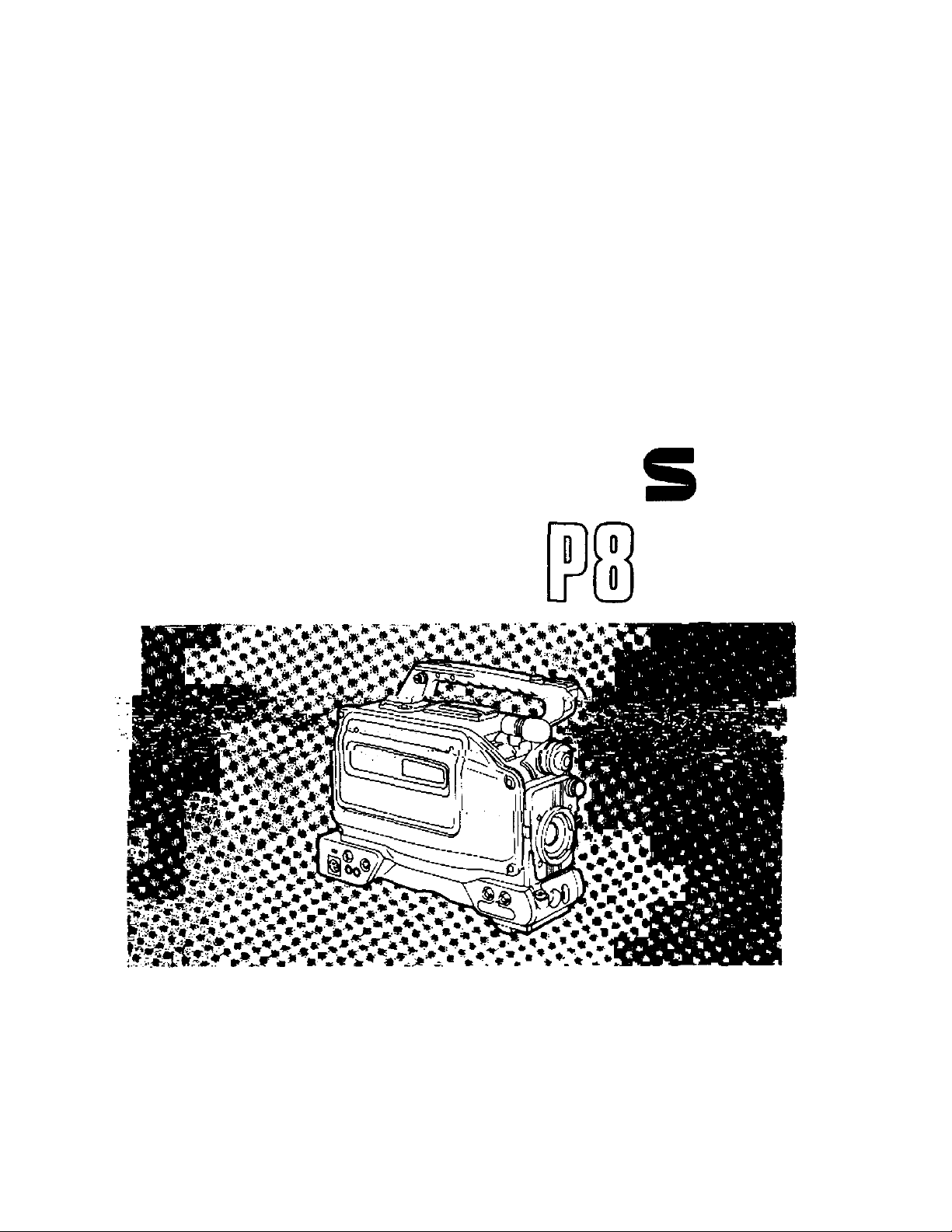
Instructions
Panasonic
Professional/Industrial Video
nn
Model AG-
Up
[rIdKFo Camera/VTR
Before attempting to connect, operate or adjust this product, please read these instructions completely.
VQT60S7
Page 2

1. Vibration
Avoid using this product in any location where it will be subjected to a great deal of vibration.
2. Ambient operating temperature
This product is designed to operate across a temperature range of 32“F to 104T (0°C to +40°C). Adequate care should be
taken when the product has been operated outside this range since it may develop differences in interchangeability or it may
not function properly, and its active service life will be shortened.
3. Rain, humidity and dust
Minimize operation in the rain or when the humidity level is high since condensation will form inside the product, thereby
causing failures. Take care when using the product in very dusty locations since dust will find its way inside the product which,
in particular, will cause a deterioration in its characteristics.
4. Sunlight
Do not point the lens in the camera section at the sun with the iris open. Neither should the viewfinder’s eyepiece be pointed at
the sun. Failure to heed this warning may cause malfunctioning inside the product.
5. Handling
Do not drop the product or subject it to impact. Failure to heed this warning will cause malfunctioning. Also, do not poke
objects inside the product while the cassette cover is in the raised position.
6. Strong electrical and magnetic fields
Bear in mind that using this product in an extremely strong electrical or magnetic field may result in interference with the
picture on the screen or with the sound.
7. Video tapes
VHS or S-VHS tapes can be used.
Use tapes up to 160 minutes in length. No guarantees can be given in the event that a 180-minute tape is used.
CAUTION
RISK OF ELCCTRIC SHOCK
Ék.
CAUTION: TO REDUCE THE RISK OF ELECTRIC SHOCK.
REFER SERVICING TO QUALIFIED SERVICE PERSONNEL.
DO NOT REMOVE COVER (OR BACK).
NO USER-SERVICEABLE PARTS INSIDE.
A
A
DO NOT OPEN
The lightning flash with arrowhead sym
bol, within an equilateral triangle, is in
tended to alert the user to the presence
of uninsulated "dangerous voltage"
within the product’s enclosure that may
be of sufficient magnitude to constitute a
risk of electric shock to persons.
The exclamation point within an equi
lateral triangle is intended to alert the
user to the presence of important
operating and maintenance (service) in
structions in the literature accompanying
the appliance.
A
FCC NOTE:
This device complies with Part 15 of the FCC Rules.
To assure continued compliance follow the attached
installation instructions and do not make any un
authorized modifications.
This equipment has been tested and found to comply
with the limits for a Class A digital device, pursuant to
Part 15 of the FCC Rules. These limits are designed to
provide reasonable protection against harmful inter
ference when the equipment is operated in a commer
cial environment. This equipment generates, uses,
and can radiate radio frequency energy and, if not in
stalled and used in accordance with the instruction
manual, may cause harmful interference to radio com
munications. Operation of this equipment in a residen
tial area is likely to cause harmful interference in which
case the user will be required to correct the inter
ference at his own expense.
CAUTION:
TO REDUCE THE RISK OF FIRE OR
SHOCK HAZARD AND ANNOYING INTER
FERENCE, USE THE RECOMMENDED AC
CESSORIES ONLY.
is the safety information.
WARNING:
TO REDUCE THE RISK OF FIRE OR
SHOCK HAZARD, DO NOT EXPOSE THIS
EQUIPMENT TO RAIN OR MOISTURE.
Page 3

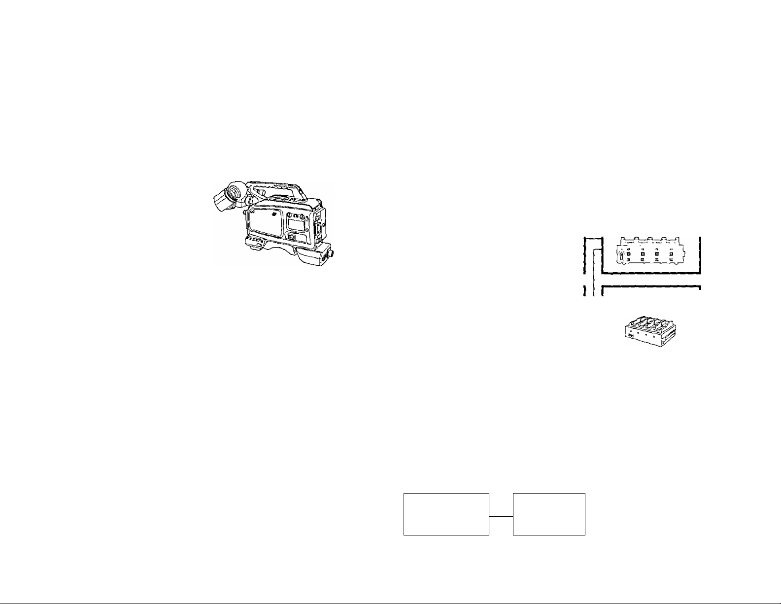
Camera recorder with compact size, light weight and low power
consumption
Camera with high picture quaiity
• Smear is slashed thanks to the adoption of a 1/2-inch, 380,000-pixel FIT CCD.
•A stable, high picture quality is assured over a prolonged period of time thanks to digital processes.
•This is a high-sensitivity product with a standard sensitivity of 2000 lux at f/8 (minimum illuminance of 2 lux).
•The electronic shutter comes with a synchro shutter function.
VTR with high picture quaiity handling full-size S-VHS cassettes
•The VTR has a built-in time code reader/generator.
•With its Dolby Noise Reduction System*, this VTR can record and play back normal sound (2 channels) and Hi-Fi audio
(2 channels) at a high quality.
Other features
•The camera AGC and audio AGC circuits make shooting possible in an emergency without having to perform any settings.
•Single-step backlight compensation, setting for different scene files and other useful functions are provided.
• Many functions can be easily established by on-screen menu settings.
•A 26-pin connector makes easy work of connecting a back-up VTR.
• Phantom power (-I-48 V) can be supplied to the external micjack.
‘Dolby noise reduction manufactured under license from Dolby Laboratories Licensing Corporation.
•"DOLBY" and the double-D symbol □□ are trademarks of Dolby Laboratories Licensing Corporation.
■' !
ATTENTION:
The product you have purchased is powered
by a rechargeable battery. The battery is
recyclable. At the end of its useful life, under
various state and local laws, it may be illegal
to dispose of this battery into the municipal
waste stream. Check with your local solid
waste officials for details in your area for
recycling options or proper disposal.
Replace battery with part No. CR2032 only.
Use of another battery may present a risk of
fire or explosion.
Caution—Battery may explode if mistreated.
Do not recharge, disassemble or dispose of in
fire.
Page 4

Features
Features .......................................................................................... 3
System Chart
Controls and their Functions
Attachment and replacement of
Peripheral Units
Date & Time Settings
Power Supply
Black Balance & White Balance
Adjustments
System chart ................................................................................. 6
Controls and their functions ........................................................ 7
Attaching the lens........................................................................24
Attaching the viewfinder.............................................................25
Attaching the microphone hoider
Replacing the backup (lithium) battery
Initializing the memory and setting the Date and Time
Using the AU-BP402 battery pack
Using AC power (with AU-B110 AC adaptor)
Using the Anton/Bauer battery pack
Using Sony’s NP-1 battery..........................................................35
When supplying power from the 26P VTR connector
Adjusting the black balance .......................................................37
Adjusting the white balance .......................................................39
..............................................
.....................................
_____
...
...........................................
...........................
.........................................
.............
26
27
28
31
33
34
36
Recording
Playback
Monitoring
Normal recording .........................................................................40
Simple editing..............................................................................42
Audio recording...........................................................................43
Power save mode
Rec review ....................................................................................45
Playback........................................................................................46
Automatic S-VHS/VHS identification & playback
Tracking ........................................................................................ 47
AUDIO SELECT switch ................................................................47
Cue and review playback ............................................................48
Monitoring ....................................................................................49
........................................................................
.....................
44
47
Page 5

Time Code Signals
Time code generator settings
....................................................
50
Menu Settings
Other Functions
Troubleshooting
Maintenance
Specifications
How to set the menu items
Menu items....................................................................................55
Connector signals
Handling the phantom mic..........................................................73
Before calling the service engineer
Condensation
Head cleaning ..............................................................................75
Specifications ..............................................................................76
........................................................................
...............................................................................
.........................................................
...........................................
52
73
74
75
Page 6
Microphones
WM-L30
WV-MC35
e
M;c Holder
AG-MH800
i]
AC Adaptor
AU-B110
VTR Cable
AQ-C2605
VTR Cable
i3==a
Mil VTR
AU-55H
-
VTR
AG-6400
AG-7450A
(AG-S745
included)
AC Adaptor
AG-B640
(/)
<
0>
S'
3
o
Lens
(1/2-inch bayonet type)
a>
Ï&
S-VHS Camera recorder
AG-DP800H
Tripod Mounting Adaptor
WV-QT700
Carrying Case
SHAN'BSOO
Battery Holder
AU-M402
—
Battery Holder
SHAN-B220
Battery
AU-BP402
Battery
AU-BP220
Battery Charger
AG-B425
Battery Charger
AG-B745
fi)
0
Anton/Bauer
Battery
MAGNUM 14/
COMPAC
MAGNUM 14
PROPACK
Anton/Bauer
Battery Charger
ABC800
SONY Battery
Holder
y
n
SONY Battery
- -
NP-1/NP-90
Page 7
Controls and their Functions
Aiim^
___
Page 8
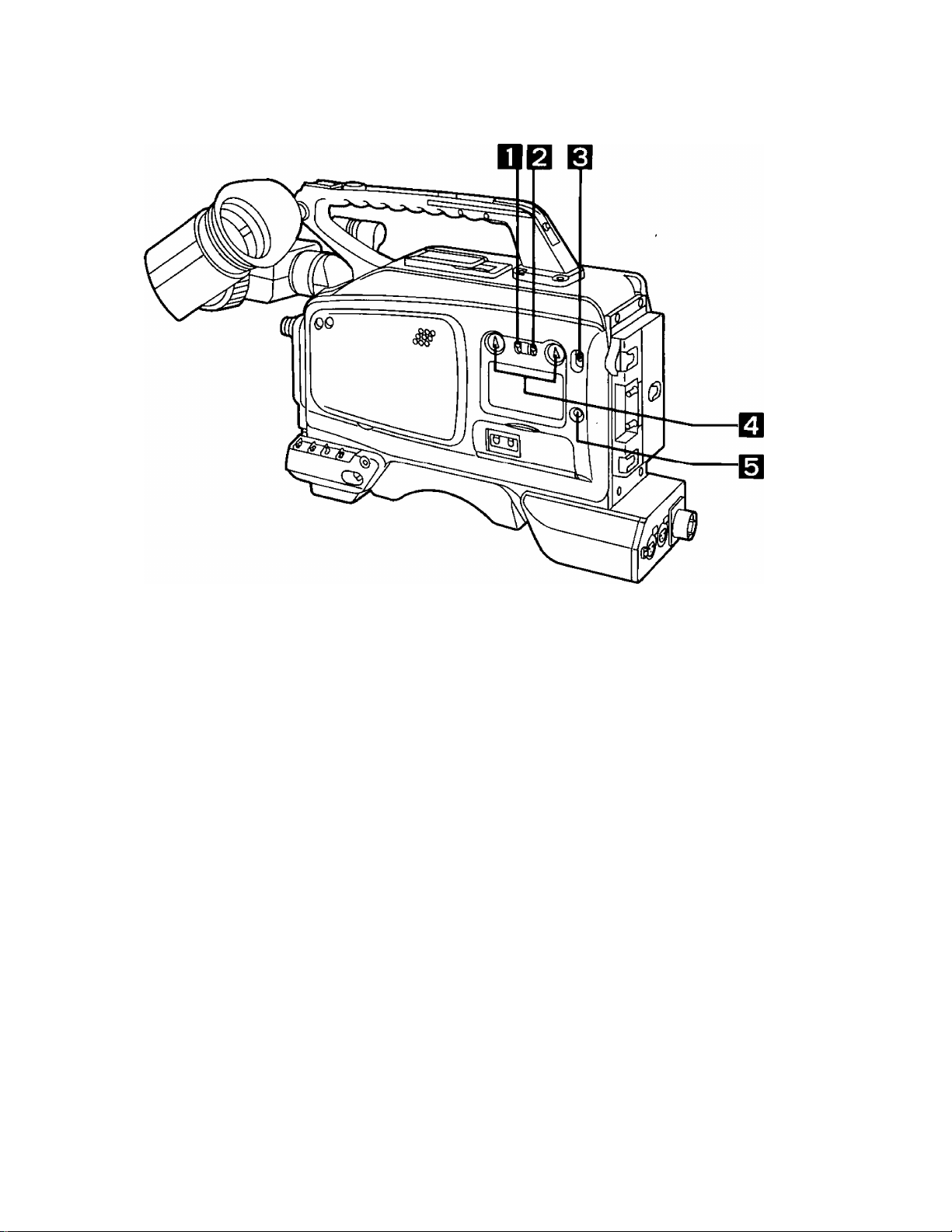
GAIN Selector Switch
AGC (Camera AGC function): The gain is automatically adjusted to the appropriate value between
When the camera screen is dark, change the position of this switch
to increase the gain and make the screen brighter.
0 dB; The switch is normally kept at this position.
HIGH: The gain of the camera video amplifier is increased to the value
(9 dB, 18 dB, 24 dB or super high gain) which has been preset
using the on-screen menu. (Increasing the gain results in an in-
crease in noise.)
0 dB and 18 dB depending on the brightness of the screen.
(If the lens iris is in the manual setting, it will be forcibly set to auto.)
The gain is set to 0 dB when the light is adequate, and if is in
creased automalicaly when the lens iris is close to being kept open
all the time and yet the amount of light is insufficient.
'The camera AGC will not function properly when a lens without an
automatic aperture function is used.
AWB Memory Selector
Switch
OUTPUT Selector Switch
A orB; When the front panel AUTO W/B BAL switch is set to AWB, the
white balance is adjusted automatically, and the adjustment value
is automatically stored in the A or B memory.
PRE: The white balance is preset to the color temperature of 3200K (the
illuminance temperature of a halogen lamp). At this position, the
front panel AUTO W/B BAL switch does not function when it is set
to AWB.
This selects either the video signals being shot by the camera or
the color bar signals.
The video signals shot by the camera are output.
CAM:
The color bar signals are output.
BAR:
8
Page 9

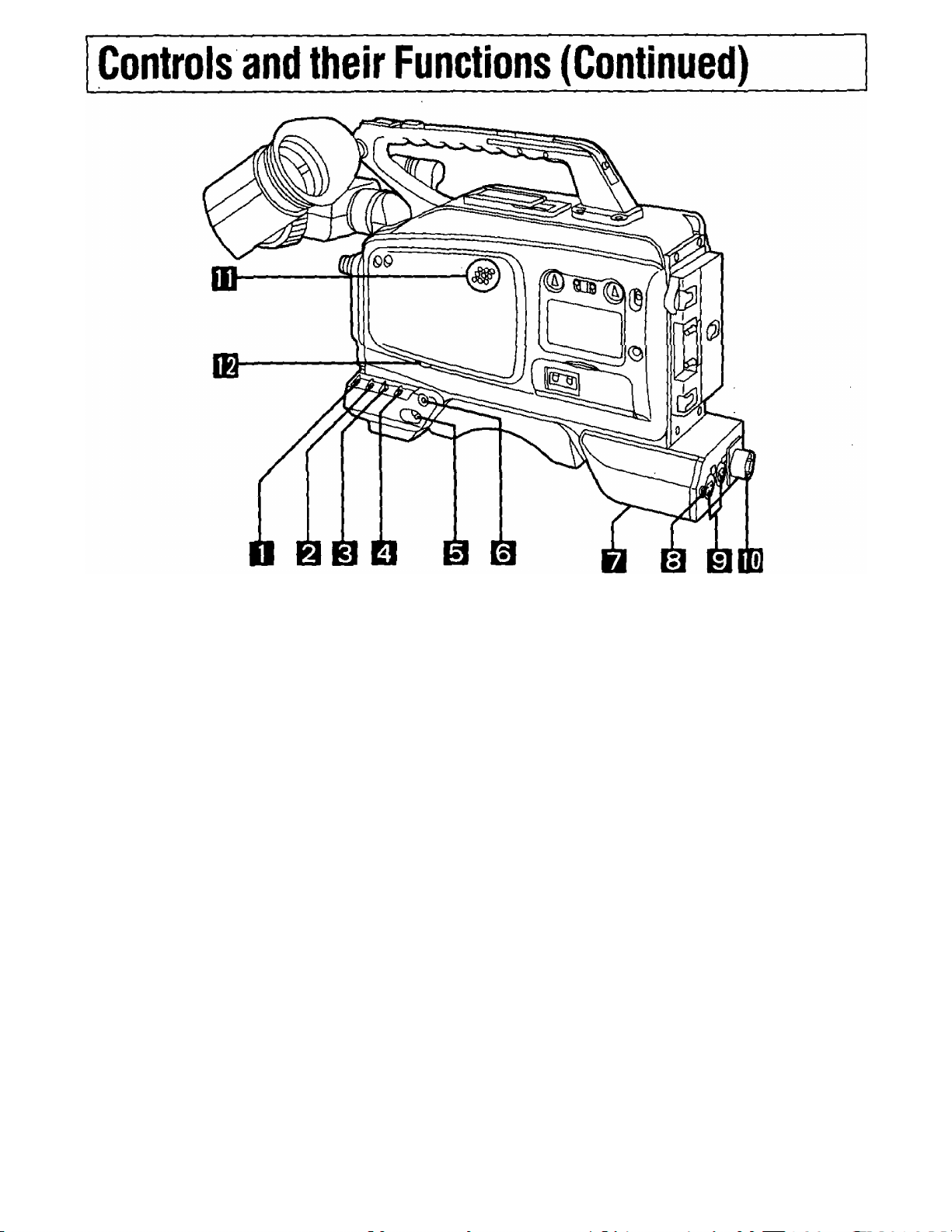
SHUTTER Switch
POWER Switch
This sets the electronic shutter ON or OFF.
OFF: The electronic shutter is not activated.
ON: The electronic shutter is activated. The shutter speed is set using
the SET + or SET - switch.
S/S: The synchro scan shutter mode is established.
The shutter speed can be changed almost continuously from about
1/60 to 1/200 by operating the SET + and SET - switches.
ON:
The entire camera recorder is operated.
SAVE:
The recorder is set to the power save status.
The VTR START (REC start) operation can be performed but it
takes some moments for the recording to commence. The power
save mode is restored when the VTR START (REC stop) button is
pressed.
OFF:
Power to the camera recorder is switched off.
MODE CHECK Button
BREAKER Button (Bottom panel)
Earphone jack
Audio Input Connectors
fm 26P VTR Connector
Speaker
This enables the settings of the camera switches to be checked on
the viewfinder.
If trouble should cause an excessively high current to flow inside
the camera recorder, the circuit breaker is tripped to cut off the
power automatically and protect the unit. Push this button in after
inspecting inside the product and taking corrective action. The
power is restored if no trouble has occurred.
The sound can be monitored by connecting an earphone to this
jack. When connected, no sound is heard through the speaker.
External microphones or line input signals are connected to these
connectors.
This is for a back-up VTR. The AG-7400 VTR or similar model can
be connected.
•Do not connect the Remote Control Unit (RCU).
The sound can be monitored through this speaker,
•The sound from the speaker is automatically cut off when an
earphone is connected to the earphone jack.
•The MONITOR switch is used to select the channel whose sound
is to be monitored.
Audio Monitor Level Control
This is used to adjust the volume of the sound which is being
monitored.
Page 10
Controls and their Functions (Continued)
Scene File Selector Button
Super Iris Button
Normal mode: Normal shooting takes place in this mode.
Super iris mode: Used for backlight shooting.
This enables scene files to be selectd. For details, refer to the next
page.
Press this button to toggle between the normal mode and super Iris
mode.
Note: This function operates when the lens is in the automatic iris
adjustment mode.
Filter Selector Control Set this control as shown below according to the light sources
illuminating the subject.
Control No. and color temperature of filter
Control No. Color temp. Shooting condition
Sunrise, sunset, subjects
1 3200 K
2
3
5600 K+
1/8 ND
5600 K
illuminated by incandescent
bulbs
Outdoors under a clear sky
Outdoors on a cloudy/rainy day
Viewfinder
Shoulder Strap Mount
This is used to attach the shoulder strap provided with the product.
10
,E
Page 11
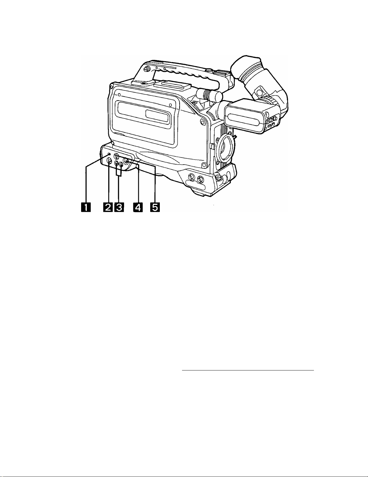
Power Selector Switch
BATT/EXT DC:
VTR:
This selects the power supply to be used.
Set to this position when supplying power from the external DC
input socket or battery.
Set to this position when supplying power from the 26P VTR con
nector.
External DC Input Socket
AUDIO OUT Connectors (Phono jacks)
VTR VIDEO OUT Connector (Y/C)
VTR VIDEO OUT Connector (BNC)
When the video signals which are output from
the VTR VIDEO OUT connector (YC or BNC)
are viewed on an underscanning TV monitor,
parts along the left edge of the picture will
have no color. This is not, however, indicative
of malfunctioning.
The AC adaptor is connected to this external power input socket,
and when it is connected, power is automatically supplied from the
external source.
Scene file selection
When the scene file selector button is pressed, the settings
change in the sequence given below:
pNQRMAL-^FILE A->FILE B^FLUO.LAMP^SPARKLING^SPECIAL-|
NORMAL: For the standard picture quality
FILE A: For file A with the picture quality set by the
user
FILE B: For file B with the picture quality set by the
user
FLUO.LAMP: For improved color reproduction under fluo
rescent lighting
SPARKLING: For darkening the color and making the pic
ture sharper.
SPECIAL: The colors are made lighter and soft images
are produced.
11
Page 12
Controls and their Functions (Continued)
EBIQ [BfQIB
PEAKING Control
CONTRAST Control
BRIGHT Control
TALLY ON/OFF Switch
OFF:
ZEBRA ON/OFF Switch
OFF:
CHARACTER ON/OFF Switch
OFF:
Turning this control intensifies the outlines of the images in the
viewfinder for easier focusing. However, this has no effect on the
camera’s output signals.
This adjusts the contrast of the image in the viewfinder. However, it
has no effect on the camera’s output signals.
This adjusts the brightness of the image in the viewfinder. Turning it
clockwise makes the image brighter. However, it has no effect on
the camera’s output signals.
ON:
The tally lamp on the front of the viewfinder lights.
The tally lamp on the front of the viewfinder does not light.
ON:
A zebra pattern is displayed in the viewfinder.
No zebra pattern is displayed.
This turns the character which are displayed in the viewfinder ON or
OFF.
ON:
Characters are displayed in the viewfinder.
No characters are displayed in the viewfinder.
12
Page 13

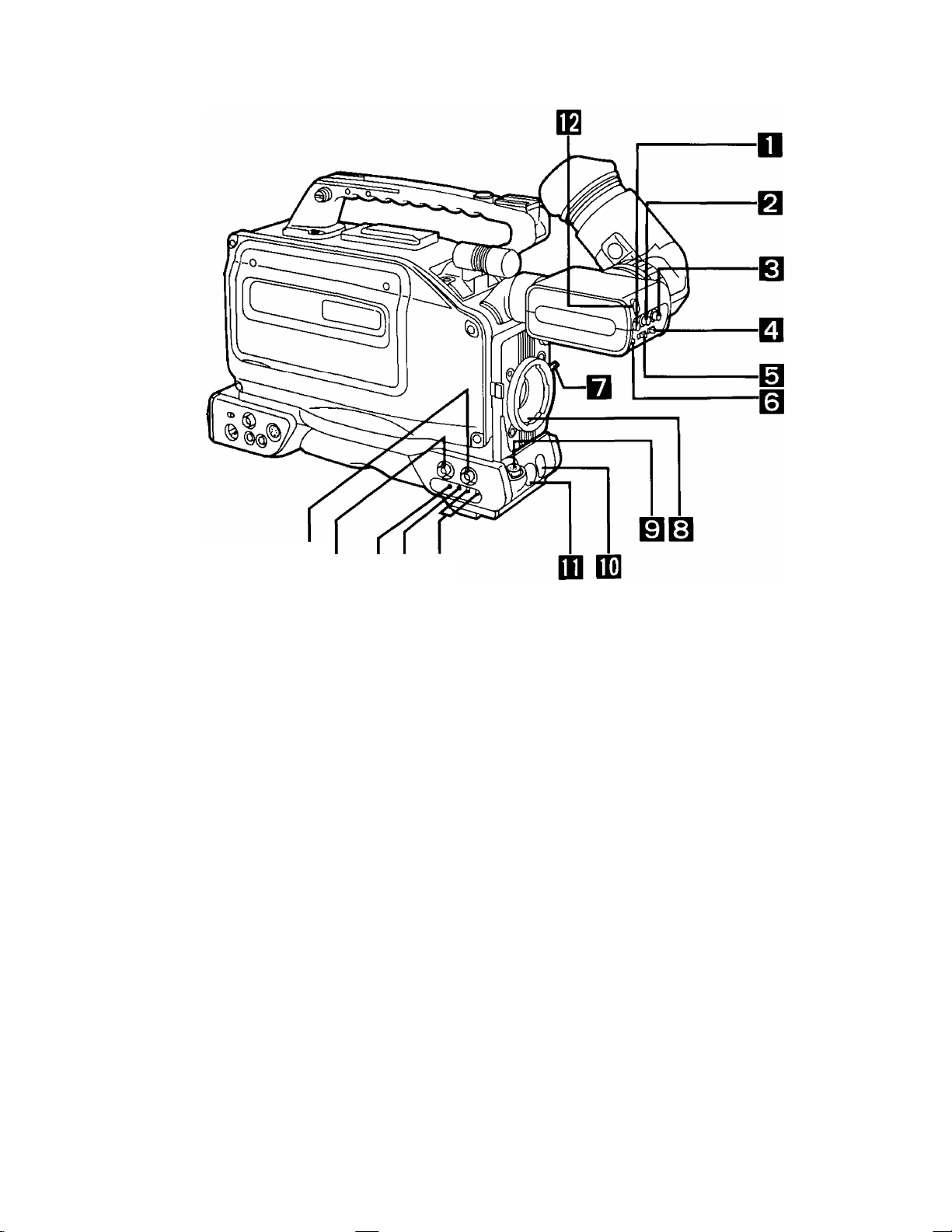
Lens Clamp Lever
After attaching the lens to the lens mount, tighten this lever to hold
the lens in place.
m
Lens Mount (Bayonet type)
LENS Connector (12-pin)
AUTO W/B (WHITE/BLACK)
BAL Switch
AWB:
ABB:
VTR START/STOP Button
TALLY Lamp
CAMERA GENLOCK IN
Connector (BNC)
The lens is attached to this mount.
The connecting cable of the tens is connected to this connector. For
a detailed description of the lens to be used, refer to the Operating
Instructions accompanying the lens.
The white balance is adjusted automatically.
Setting the AWB Selector switch at the side to A or B and then
operating the AUTO W/B BAL switch enters the adjusted value into
memory A or B. Bear in mind that this operation will not be per
formed when the selector switch has been set to PRE.
The black balance is adjusted automatically.
The value to which it has been adjusted is entered in an exclusive
memory. When it is released, the switch automatically returns to its
center position.
This is for starting or stopping the recording.
This lights while the image being shot by the camera is being re
corded by the VTR. It lights and flashes in tandem with the TALLY
lamp inside the viewfinder.
To apply genlock to the camera recorder from an external unit,
connect the unit to this connector.
EE
EE
CAMERA VIDEO OUT
Connector (BNC)
SC Rough Adjustment
Switches
SC Fine Control
Horizontal Sync Phase
Control
The camera’s encoder (composite signal) output is sent to this
connector.
These roughly adjust the subcarrier phase in the genlock mode.
This finely adjusts the subcarrier phase in the genlock mode.
This adjusts the horizontal sync phase in the genlock mode.
13
Page 14
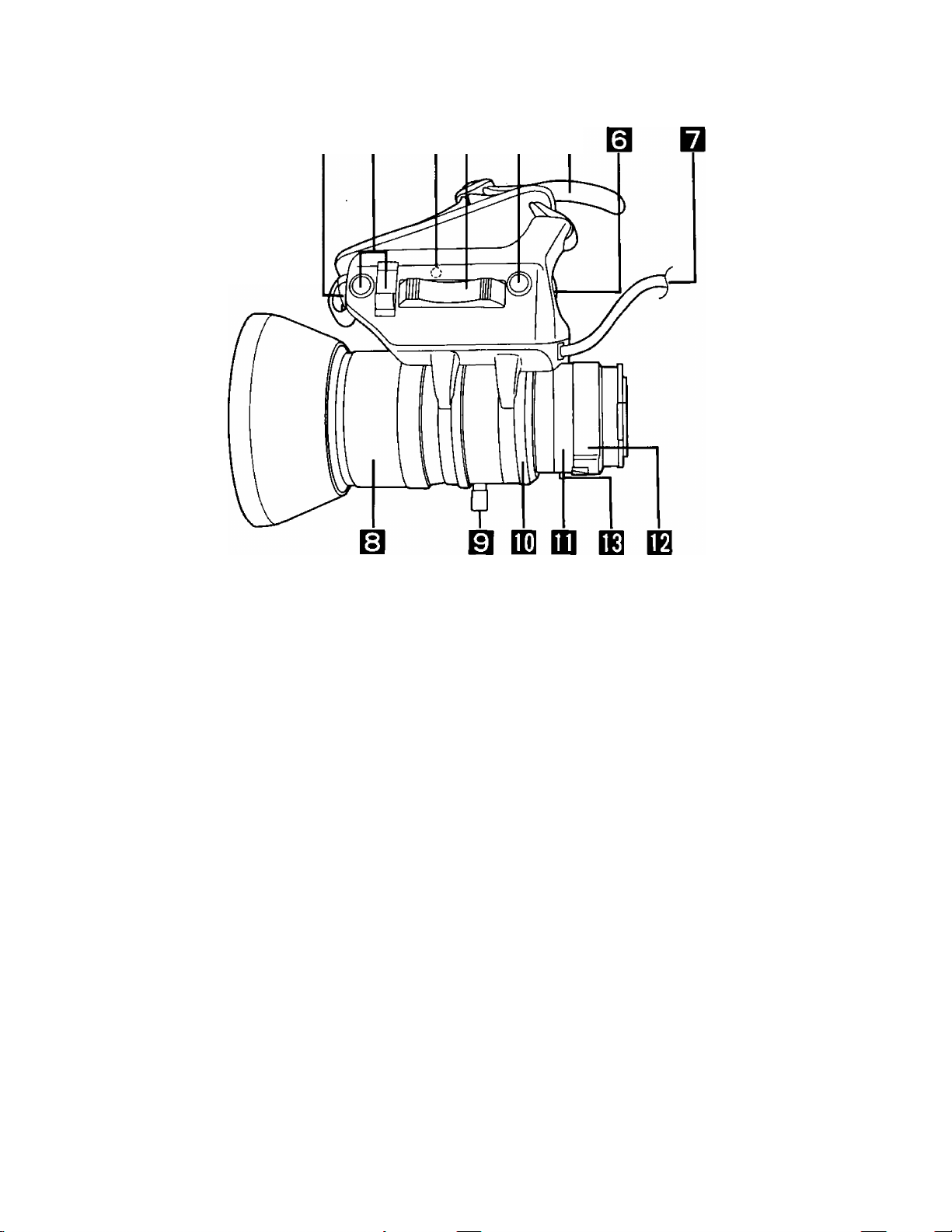
о в ввшш
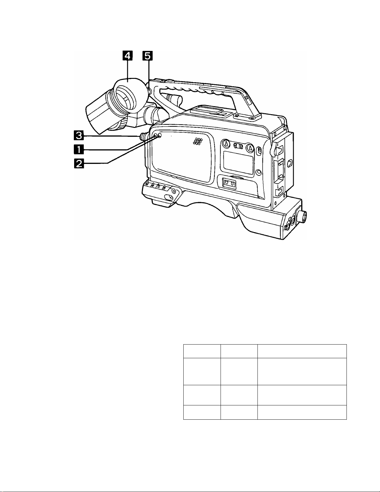
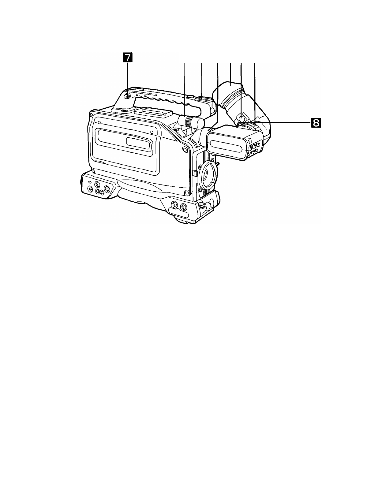
Microphone
Accessory Hole
Viewfinder Clamp Ring
Eye Cup (Eyepiece)
Eye Cup Removal Lever
Viewfinder Stopper
Shoulder Strap Mount
Diopter Adjustment Control
This is a compact, unidirectional type of microphone. However, by
replacing it with the optional holder, a highly directional microphone
can be attached instead.
This is for mounting video lights or other accessories.
This is used to attach and detach the viewfinder. By loosening the
clamp ring, the viewfinder can be rotated by 90° so that it is pointing
upward.
This is used to remove the eye cup. Move the lever in the direction
shown by the arrow and then simply slide the eye cup to remove it.
This is used to adjust the viewfinder’s position. Loosen the stopper
and move the viewfinder to the left or right to adjust its position.
After the position has been adjusted, tighten the stopper to hold the
viewfinder in place.
This is used to attach the shoulder strap provided with the product.
This is adjusted to the eyesight of the operator so that he or she can
clearly see the images on the viewfinder screen.
Eyepiece front/back
adjustment ring
At the unlock position, the eyepiece can be moved further toward
the front or back. After moving the eyepiece to the desired position,
lock the ring to secure it there.
14
Page 15

Page 16
Controls and their Functions (Continued)
SKIFT 1 SET + STAtTNA
060011
dD
TCUBCCUKTERREC FREE
cu) dp
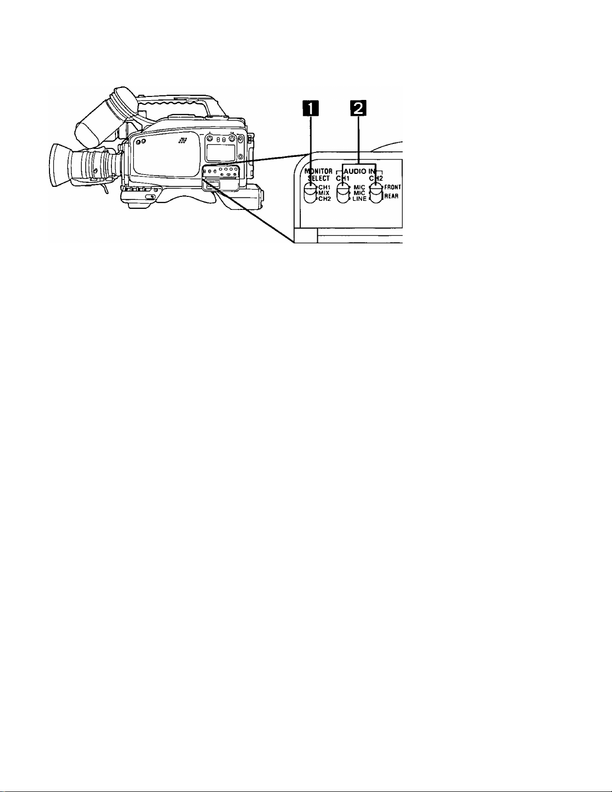
MONiTOR Switch
AUDIO IN Selector Switches
FRONT MIC:
REAR MIC: For connecting an external microphone to the audio input connec
REAR LINE: For connecting line signals to the audio input connector (XLR 3P)
SHIFT Button
SET-, SET + Buttons
This is for selecting the speaker or earphone sound,
cm: The CH1 sound can be monitored.
MIX: The CH1 and CH2 mixed sound can be monitored.
CH2: The CH2 sound can be monitored.
These switches select the CH1 and CH2 audio inputs.
For recording the audio signals from the microphone built into the
camera.
tor (XLR 3P) on the rear panel and recording its audio signals.
on the rear panel and recording them.
This is used for time code generator and menu item settings.
These are used for changing the time code generator, menu, elec
tronic shutter speed or synchro scan shutter speed settings and for
adjusting the VTR tracking,
16
Page 17

START Button
MENU ON/OFF Selector
Switch
TC/UB/COUNTER Selector
Switch
COUNTER:
REC/FREE Selector
Switch
Press this button to indicate the time code generator setting on the
display. The button is used to make the time code generator and
menu item settings.
OFF: The switch is normally kept at this position when the camera re
corder is being operated.
ON: For displaying or changing a menu item.
For setting or displaying the time code data.
TC:
For setting or displaying the user bit data.
UB:
For indicating the reei counter on the display.
For counting the time code only in the VTR’s recording mode;
REC:
REGEN operation is performed when LTC is ON (set using the
menu item).
FREE: For counting the time code in the same way as for the time regard
less of the VTR mode.
17
Page 18
CTL TCUB COUNTER-M SVHS;
DF TCG
REMAIN
nnooriooo
UU'UU'UU UU ~
I h I min I s I frm i
E BATT F
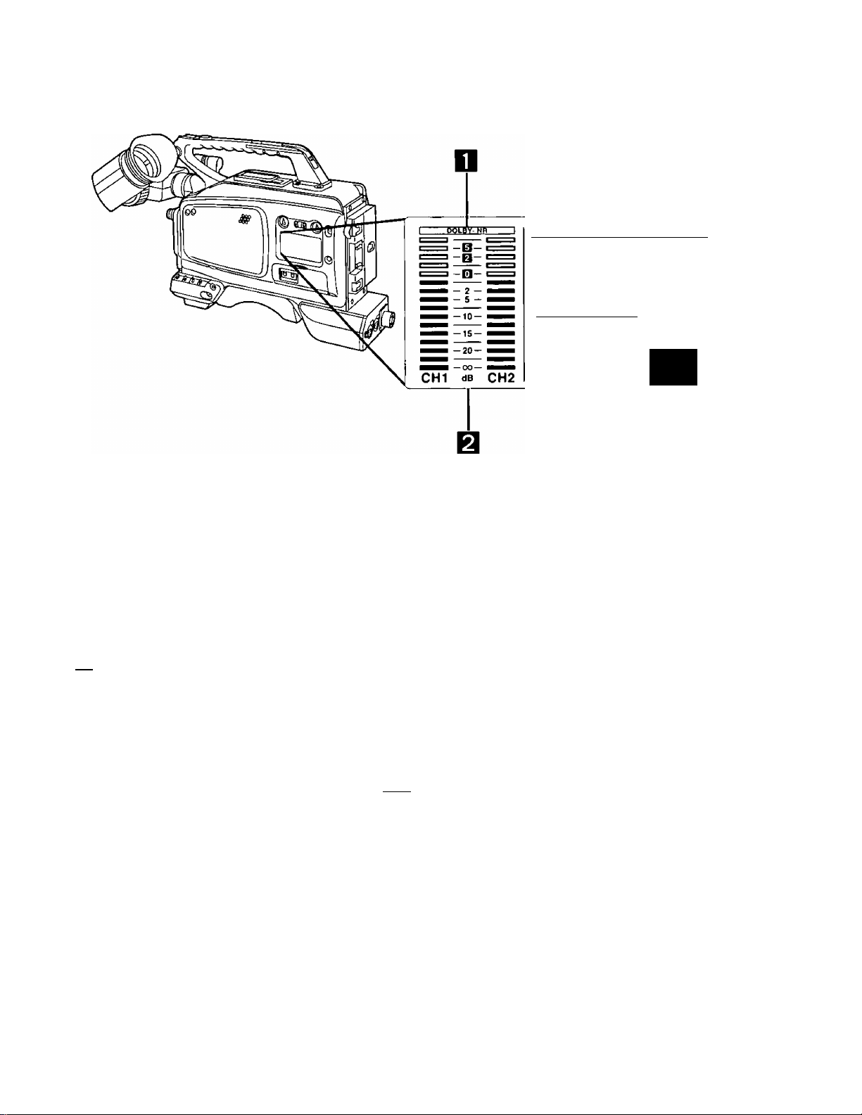
Display
□ DOLBY-NR display
Q Audio level meter
Ft Mode displays
RF SERVO HUMID
SLACK END
Lights when the DOLBY NR menu item has been set to ON.
Indicates the CH1 and CH2 audio levels.
TC: Lights when the counter is in the TO (time code) mode.
UB: Lights when the counter is in the UB (user bit) mode.
DF: Lights when the time code is in the DF (drop frame) mode.
COUNTER: Lights when the counter is in the reel count mode.
TCG: Lights when the counter is in the TCG (time code generator) mode.
—M: Lights in the counter memory mode (0000 stop mode).
CTL: The counter memory mode is set using the menu item.
SVUS: Lights in the S-VHS mode.
B551: This denotes that a cassette tape has been loaded.
OD
18
Page 19

Counter
Remaining battery level display
This indicates the time code and user bit data in units of hours,
minutes, seconds and frames. It serves as a 4-digit counter in the
reel count mode.
REMAIN
0 o * o o * o o * o o
UU'UU'UU'UU
1 h I min I s I frm i
This indicates the remaining battery levei.
The battery is set using the menu item. For further details, refer to
"How to set the menu items” (page 52).
Different kinds of batteries and their operating times are shown in
the tabie below. (The operating times shown apply when the unit is
used in the continuous recording mode.)
Bear in mind that the actual operating time will vary greatly depend
ing on what shooting methods are used, whether old or new batter
ies are used and on other such conditions.
Warning displays
Battery
Model
number
TRIMPAK14
DIGITAL
DIGITAL
HD MAG 14
AU-BP402 Panasonic
AU-BP220
NP-1B
RF: Flashing denotes that the video heads are clogged.
SERVO: Flashing denotes that the servo system is not iocked.
HUMID: Fiashing denotes that condensation has formed on the cylinder.
SLACK: Flashing denotes tape slack or some other problem in the tape
transport system.
END: Flashing denotes that the tape has come to its end.
Manufacturer Capacity
Anton/Bauer
Anton/Bauer 60 WH
Panasonic
SONY
40 WH 90 minutes
4 AH 140 minutes
2,2 AH 70 minutes
2.3 AH 70 minutes
Operating time
(during
continuous
recording)
160 minutes
19
Page 20

Viewfinder display
LED displays
o o o
Alinin TALLY RTBY
AUDIO (yellow): Not used by this system.
TALLY (reiDj Liahts durina recordinq; flashes durina taoe ap-
Page 21

Character displays (displays when changes have occurred)
•Camera warning display
-+++ Super Iris
-I- + + Camera warning
display
Filter display |
I AWB/ABB operation display |
1 AWB memory display]
I Electronic shutter speed display |
I
Scene file display |
I
VTR warning display |
FS.B
1E.5V
PAUSE TCG 00:00:0a
QE-21-94 17:35:10
A warning message appears when AWB or ABB has not been set
properly.
• Filter display
The filter number and name are displayed for about 3 seconds
when the CC filter setting is selected.
•AWB/ABB operation display
"ACTIVE" appears while the AWB or ABB operation is in prog
ress. “OK” appears upon completion of the operation.
•AWB memory display
This indicates the AWB channel A and B memory statuses and
switch status. The displays appear for about 3 seconds when the
AWB switch setting is selected.
•Electronic shutter speed display
This indicates the electronic shutter speed. When the electronic
shutter has been selected or the shutter speed has been
changed, the display appears for about 3 seconds.
•Scene file display
This indicates the name of the present scene file for about 3 sec
onds when the scene file selector button is pressed.
•VTR warning display
This appears when trouble has occurred in the VTR.
21
Page 22
OB IQB O □
Automatic Iris Controi
Lens Iris Selector Switch
[IRIS]
Power Zoom Control Switch
Hand Strap
Return Switch
[RET/REC CHECK]
This enables the automatic iris speed to be adjusted.
The control can be found inside when the rubber cap is removed.
The speed is increased by turning the control clockwise but bear in
mind that turning it too far will cause hunting (the operation does not
stop).
Be absolutely sure to adjust the control when replacing the lens or
when attaching the lens for the first time.
A: The iris is adjusted automatically.
M: For adjusting the iris manually.
Note: When the camera’s AGC function has been activated, the
iris is adjusted automatically even if this switch is set at the
[M] position.
The zoom can be controlled electrically by setting the power/
manual zoom selector switch to SERVO and by pressing this con
trol switch. The zoom speed changes according to how firmly the
switch is pressed.
Adjust the strap to fit the size of your hand.
This switch is used to check recordings. When it is pressed during
recording pause, the recording check function is activated to play
back the section which has been recorded and then establish the
recording pause mode.
22
Page 23

VTR Start/Stop Switch
This easily accessible switch is for handily starting and stopping the
VTR recording, When it is pressed once, recording commences;
when pressed again, recording stops. When this lens is mounted
on the camera recorder, the VTR can be controlied by either this
switch or the VTR start/stop switch on the camera.
Lens Cable (12-pin)
Focus Ring
Zoom Ring
Qj] Iris Ring
Flange Back Control Ring
Macro Ring
Flange back clamp knob
Power/Manual Zoom Selector Switch
This cable is connected to the iens connector.
Turn this ring to bring the subject into focus.
The size of the picture can be adjusted by setting the power/manuai
zoom selector switch to MANU and then turning this ring.
The iris is adjusted by setting the lens iris selector switch to M and
then turning this ring.
Be absoiutely sure to adjust this ring when replacing the lens or
when attaching the lens for the first time.
The flange back adjustment is performed by loosening the flange
back clamp knob and then turning this ring.
Close-up shooting is achieved by setting the lens all the way to the
wide position and then rotating this ring.
Use this knob for clamping purposes after the flange back has been
adjusted.
When this is set to SERVO, the zoom can be adjusted using the
power zoom control switch; when set to MANU, it can be adjusted
using the zoom ring.
23
Page 24
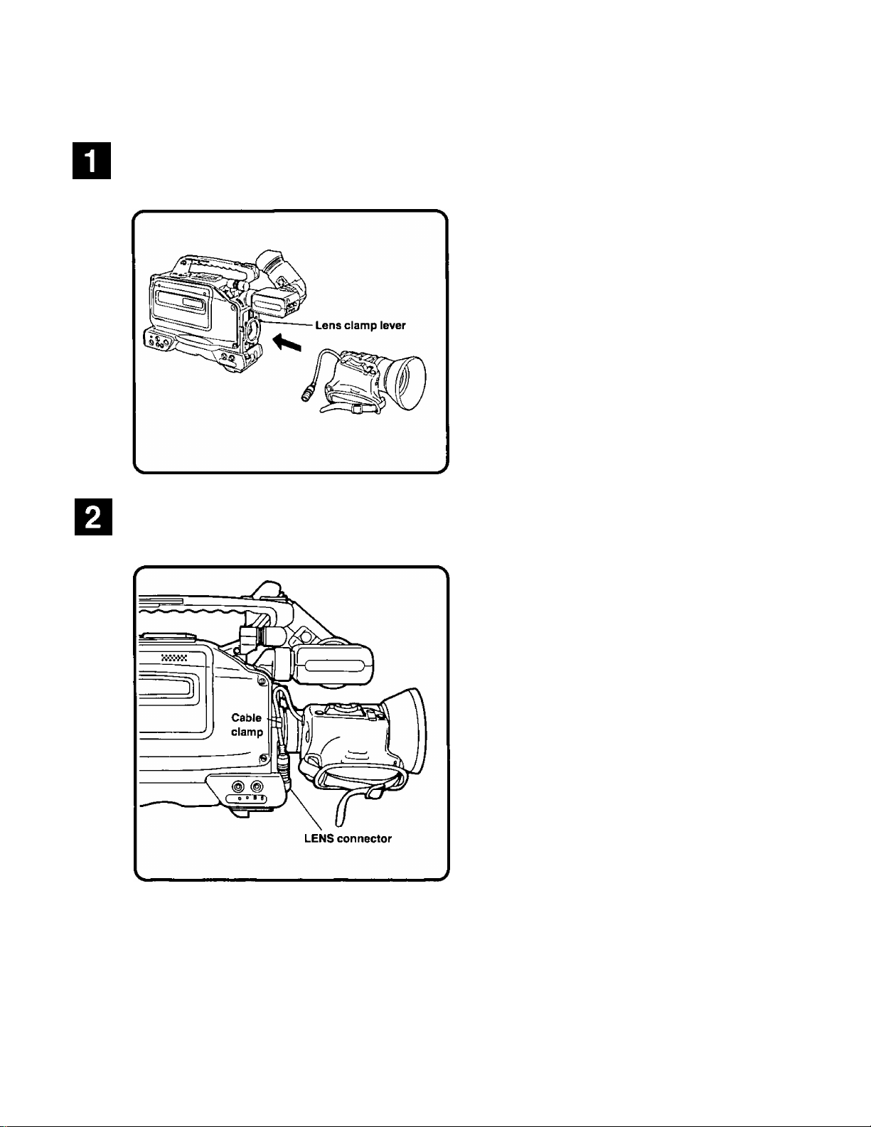
Attaching the lens
Align the lens with the lens mount on the camera recorder, insert the
lens Into the mount, and secure it in place using the lens clamp lever.
Connect the cable to the LENS connector, and secure it In place using
the cable clamp.
NOTE
For details on the handling of the lens, refer to the Operating Instructions accompanying the lens.
•When the lens has been detached from the camera recorder, attach the lens cap to protect the unit.
24
Page 25

Attaching the viewfinder
Align the positions of the marks (red) on the viewfinder and camera
recorder, and insert the viewfinder.
Turn the viewfinder clamp ring to clamp the viewfinder in place.
tated by 90°.
25
Page 26

Attaching the microphone holder
Remove the microphone of the main unit.
screws and then remove the connector.
Attach the microphone holder.
Attach the holder by following the procedure for remov
ing the microphone in reverse.
26
Page 27

The unit is shipped from the manufacturing plant with the back-up battery already installed. There is no need to install this battery
immediately after purchasing the unit. Skip this section and move on to the next procedures which are for initializing the memory
and setting the date and time.
Remove the battery holder from the main unit.
Insert the lithium battery into the battery holder.
(Make sure the “+” and polarities are aligned properly.)
With the triangular marks on the main unit and on the battery holder facing each other, fit the battery holder back into the main unit.
NOTE
The service life of this battery is approximately one year. When it has mostly discharged, the “BACK UP ВАТТ EMPTY" display
will appear in the viewfinder for several seconds when the power switch is set to ON.
Replace with a new lithium battery (Panasonic CR2032).
27
Page 28

Initializing the Memory and Setting the Date and Time
When the back-up battery has been replaced, initialize the memory and set the date and time before proceeding with any other
operation.
Set the POWER switch to ON.
When the MENU ON/OFF selector switch is set to ON, the setting screen (MENU) appears in the viewfinder.
MAIN MENU
01 EVF DISPLAY
□2 CAMERA SETTING
03 VTR OPERATION
04 TIME/DATE
05 TIME CODE
06 AUDIO
07 BATTERY
-►08 DIAGNOSIS
00 MENU INITIALIZATION
---END OF DATA---
- DIAGNOSIS 01 ERROR LOG DATA
02 CYLINDER 1800h
03 CAMERA Ver <1.0)1.1
04 SERVO Ver A<1.1>
05 SYSCON VerB<1.2)
-►06 MEMORY INIT.?
* ♦PREVIOUS MENU
---END OF DATA---
While monitoring the viewfinder display, press the SHIFT button until the arrow at the far left is aligned with “DIAGNOSIS”.
________________
When the START button is pressed, the self-diagnosis (DIAGNOSIS) screen appears.
Press the SHIFT button until the arrow at the far left is aligned with “MEMORY INIT.?”.
Press the START button.
“INlT.?” now changes to “INITIALIZED".
The memory initialization is now completed. The next step is to set
the date and time. {See next page.)
28
Page 29

SEE
Press the SHIFT button until the arrow at the far left is aligned with “PREVIOUS MENU”,
- DIAGNOSIS - MAIN MENU
Q1 ERROR LOG DATA
Oe CYLINDER 1 BOOh OE CAMERA SETTING
□3 CAMERA Ver <1.0)1.1 03 VTR OPERATION
□4 SERVO Ver A<1.1)
05 SYSCON Ver B<1.E>
06 MEMORY INIT.?
♦PREVIOUS MENU
---END OF DATA--- ---END OF DATA---
01 EVF DISPLAY
-^04 TIME/DATE
05 TIME CODE
06 AUDIO
07 BATTERY
08 DIAGNOSIS
09 MENU INITIALIZATION
When the START button is pressed, the MAIN MENU appears.
Press the SHIFT button until the arrow at the far left is aligned with
“TIME/DATE”.
____________________ ___________
■ •
When the START button Is pressed, the calender and clock setting screen appears.
- TIME/DATE -
-►01 YEAR 94
MONTH
02
03 DAY 06
04 HOUR
05 MINUTE 55
• TIME/DATE SET
+ ♦ PREVIOUS MENU
---END OF DATA---
07
16
29
Page 30

Initializing the memory and setting the date and time (Continued)
Set the date and time using the SHIFT, SET + and SET - buttons.
Press the SHIFT button until the arrow at the far left is aligned with
“TIME/DATE SET”,
- TIME/DATE 01 YEAR
OB MONTH
03 DAY 06
04 HOUR
05 MINUTE 55
«TIME/DATE SET
* * PREVIOUS MENU
---END OF DATA---
94
07
16
When the START button is pressed, the data is entered, and the
screen display changes to the MAIN MENU.
Finally, set the MENU ON/OFF selector switch to OFF.
30
Page 31

Using The AU-BP402 Battery Pack
Before using the battery, charge it using the AG-B425 battery charger. It takes about an hour to charge the battery. For further
details, refer to the Operating Instructions of the AG-B425 battery charger.
Remove the Anton/Bauer battery holder.
Connect the cable from the camera recorder to the cable of the AU-M402 battery case.
31
Page 32

Use a screwdriver to mount the AU-M402 on the camera recorder.
The holes for tightening the screws are visible when the lid is opened and the rubber caps are pulled away. Mount the
battery case onto the camera recorder by tightening the screws with a screwdriver. Tighten up the screws as far as
they will go.
Connect the battery pack’s plug to the connector inside the battery
* case, and insert the battery pack into the case.
Make absolutely sure that the camera recorder’s power is off before attempting to connect or disconnect the plug.
Set menu item 7 “BATTERY” (battery selection) to “Ni-Cd 12 V”,
For further details, refer to “How to set the menu items” (page 52).
32
Page 33

Connect the camera recorder’s external DC input socket to the DC OUT connector on the AU-B110 AC adaptor.
Turn on the AC adaptor’s power.
Set the camera recorder’s power switch to ON.
Check the pin signals of the external DC input socket when an external power supply other than the AU-B110 AC
adaptor is to be used.
OFF SAVE ON
POWER
Pin No. Signal
1
2,3
4
GND
—
H12 V
NOTES
•When both the battery pack and AC adaptor have been connected, the power from the AC adaptor has priority in terms of which
power is supplied to the camera recorder.
•When the AC adaptor is used, the low battery level warning may appear depending on the battery selection menu setting. In a
case like this, it is recommended that “Ni-Cd 12 V” be set on the menu as the battery selected.
•When using the AC adaptor, be absolutely sure to turn the unit’s POWER switch to ON only after turning on the AC adaptor’s
power. If this sequence is reversed, the AC adaptor’s output voltage will rise slowly with the result that the unit may not operate
properly.
33
Page 34

Charging the pack
Before using the battery pack, charge it using the battery charger made by Anton/Bauer. For the charging time and
other details, refer to the Operating Instructions of the battery charger used.
Attach the Anton/Bauer battery pack.
Insert the pack in the direction shown by the arrow, and then slide it into place.
Set menu item 7 “BATTERY” (battery selection) to the battery which is going to be used.
For further details, refer to "How to set the menu items” (page 52).
REFERENCE
Lighting power output connector
Anton/Bauer battery pack
Lighting control switch
The battery hoider
made by Anton/Bauer
comes with a iighting
power output
connector and a
iighting control
switch, which makes
it easy to attach a
iight
For details on the
lighting systems,
contact Anton/Bauer.
How to remove the battery pack
Pull the disengaging lever on the battery holder all the way down and, while keeping the lever down, slide the battery pack in the
direction shown by the arrow.
Page 35

Before proceeding to use this battery, charge it using the Sony battery charger which is specially designed for it. Refer to the
operating instructions accompanying the battery charger used for details on the charging time, etc.
Remove the battery holder made by Anton/Bauer.
Mount the screws for the accessory battery installation terminal (NP-1).
35
Page 36

Install the battery holder made by Sony.
As shown in the figure on the left, first install the battery case whose
cover has been removed, and then install the removed cover.
O Tighten the installation screws.
0 Tighten the power supply contact screws.
0 Insert the top of the removed cover in the direction indicated by
the arrow.
O Align the holes at the bottom (metal part) of the cover with the
holes at the bottom of the case, and attach to the battery instal
lation terminal using the accessory screws.
When supplying power from the 26P VTR connector
Connect the unit ot the back-up VTR with the VTR cable.
Set the power selector switch to VTR. (See page 11.)
NOTES
•When the power selector switch is set to VTR, power is supplied from the VTR cable. The power will not be selected
automatically by connecting the power from the AC adaptor to the EXT DC IN connector.
•When supplying power from the back-up VTR through the VTR cable, bear in mind that the supply voltage may drop.
(This unit has an undercutting voltage of 10.5 V.)
36
Page 37

Black Balance Adjustment
■ Check to make sure that the lens cable is
connected to the LENS connector. (This
adjustment is effective only when the
lens cable is connected to the LENS
connector.)
Set the POWER switch to
Press the AUTO W/B BAL switch to the ABB position.
The black balance adjustment is completed in about 20 seconds,
and the adjustment value is automatically stored in the memory.
A display similar to the one shown on the left appears on the view
finder screen while the adjustment is in progress.
•Upon completion of the black balance adjustment, the display
changes to “ABB: OK".
•The “ABB: NG" display appears if it was not possible to adjust the
black balance.
NOTES
•The camera is automatically shielded from the light while the black balance is being adjusted.
•When the iris is being adjusted manually, return the iris (but only with a lens which is recommended by Panasonic) to a place
near its original position after having adjusted the black balance. Start shooting only after the iris has been set to the appropriate
value.
•When the AUTO W/B BAL switch is pressed lo the ABB position, the gain selection circuit is switched automatically, and
flickering appears several times on the screen inside the viewfinder. This is normal and not indicative of a failure.
REFERENCE
•The black balance needs to be adjusted in the following cases only:
When the camera recorder is to be used for the first time
When the difference in the temperature has changed greatly
•In the interest of maintaining a high picture quality, it is recommended that the AUTO W/B BAL switch be set to the ABB position
immediately before shooting important or memorable scenes.
37
Page 38

Black Balance & White Balance Adjustments (Continued)
White Balance Adjustment
Set the POWER switch to the ON position.
Use the filter selector control to select the color temperature
according to the lighting conditions.
When the lens iris is to be operated manually, set it to the suitable
value.
Bear in mind that it may not be possible to adjust the white balance
if the iris is not set properly. If the lens comes with an automatic iris
adjustment mechanism, set the automatic/manuat iris selector
switch on the lens to the automatic position.
Set the AWB selector switch to A or B.
/
-----------------
V
_________
i6
AWB
.A 1
■PRE
-------------
________
\
Place a white sheet of paper or handkerchief where the conditions are
the same as for the light source illuminating the subject, zoom in and
shoot the white on the screen.
A white object (sheet, cloth or wall, etc.) near the subject can be
used instead but bear in mind that the object appearing to be white
may not be perfectly white.
38
Page 39

Shoot a white object so that it is virtually at the center of the screen and occupies an area equivalent to at least one-fourth of the height and width of the screen, and set the AUTO W/B BAL switch to AWB,
NOTES
The white balance adjustment is completed in about a second.
The adjustment value is stored in memory A or B.
The display shown on the left appears on the viewfinder screen
while the adjustment is in progress.
• Upon completion of the white balance adjustment, the display
changes to “AWB: OK’’.
•The "AWB: NG” display appears if it was not possible to adjust
the white balance.
•Since hunting may occur when a zoom lens equipped with an automatic iris adjustment mechanism is used, adjust the iris gain
control provided on the lens.
For further details, refer to the Operating Instructions of the lens.
•The white balance cannot be adjusted if the AWB selector switch is set to PRE.
The switch has been adjusted in such a way that the white balance is achieved at 3200 K. When the filter selector control is set
to “1 the proper white balance at 3200 K is achieved. All that now needs to be done is adjust the black balance.
•Since the lightest part of what appears on the screen is taken to be “white” for the adjustment of the white balance, do not allow
any object lighter than the white object shot in step 6 above to appear on the screen. Incorrect operation may otherwise result.
• Do not adjust the auto white balance (AWB) with the gain turned higher than is necessary.
Doing so will cause the iris to virtually close during AWB, resulting in unstable operation.
REFERENCE
► In the interest of maintaining a high picture quality, it is recommended that the AUTO W/B BAL switch be set to the AWB
position immediately before shooting important or memorable scenes.
► It is recommended that the auto white balance be adjusted when the gain or shutter speed has been changed.
39
Page 40

Set the POWER switch to the ON position.
Press the EJECT button to open the cassette compartment.
Insert the cassette tape.
•Before inserting the tape, make sure that the accidental erasure
prevention tab on the cassette has not been broken out.
•Do not use a 180-minute tape.
Set the camera’s switches as follows.
Point the camera at the subject, and adjust the focus and zoom,
40
Page 41

Press the VTR START/STOP button to start the recording.
The REC tally lamp inside the viewfinder keeps on flashing until the
recording mode is established. Once recording commences, it
stops flashing and remains lighted.
Press the VTR START/STOP button to suspend the recording.
When the recording is suspended as shown in the figure below, the tape is rewound by about 30 frames and the rec
pause mode is established. When the recording is resumed, recording commences where the previous recording will
be slightly overlapped.
I i
NOTE
This unit does not have a function which ensures that the REC/PAUSE mode will be released after a certain period of time has
elapsed. This means that when it is kept in the REC/PAUSE mode for an extremely long period of time, the tape may be
adversely affected. As a general rule, take steps to change the operating mode every hour or so.
41
Page 42

Simple editing function
This refers to the pre-edited shooting function with which the recording of each cut is started from the pause (still picture) mode to
ensure continuity.
1 2
Operation
Press the PLAY button.
The playback picture mode is established.
Press the PLAY button again where the new cut is to be joined onto the existing recording.
The still picture mode is established.
Press the VTR START/STOP button._________________________
The rec pause mode is established.
■ B To start the recording, press the VTR START/STOP button again.
Recording now starts.
NOTE
If the VTR is kept in the still picture mode for about 5 minutes, it is automatically placed in the stop mode. Bear in mind that
smooth continuity between cuts cannot be guaranteed when recording is started from the stop mode.
42
Page 43

Select the desired input signals using the audio input selector switches.
f—
r-AUDIO IN-1
CHI CH2
MIC ¿Ci PROMT
0«if,gRE*R
J
The sanne sound is input for normal audio and Hi-Fi audio.
When the built-in microphone is used ■
When an external microphone is used ■
When line audio signals are input ^ REAR LINE
► FRONT MIC
\ REAR MIC
Turn the audio level controls clockwise or counterclockwise and
adjust them so that the audio signal levels indicated on the display’s
level meter are brought to the standard positions.
The audio signal levels can be adjusted when the AUDIO AGC
switch is OFF. If this switch is ON, the signals will be automati
cally adjusted to more or less the appropriate levels regardless
of the audio level control settings.
Howling may occur if the voiume of the audio monitor speaker is
turned up high. If this occurs, turn the audio monitor level control
and lower the volume to a level at which howling does not occur.
•When the AUDIO AGC switch is at LIMIT, the limiter will be
automatically activated when the input level of the signals is
excessively high. Therefore, first adjust the level with the
switch at OFF and then return the switch to LIMIT just in case
excessively high input signals are supplied.
43
Page 44

Page 45

When the camera’s RET button is pressed with the VTR in the rec pause mode (which is established after the tape has finished
automatically reversing), the rec review operation is performed, enabling what has already been recorded to be checked.
The playback pictures are shown in the viewfinder while the tape is playing back in the rec review mode.
<When the area near the rec review start point has not been recorded>
The playback pictures of the unrecorded part of the tape are shown in the viewfinder.
NOTE
The rec review operation is not repeated even when the rec RET button remains depressed.
45
Page 46

Set the POWER switch to the ON position.
The tape is automatically loaded onto the cylinder, the REC, PLAY
and PAUSE lamps come on, and the camera recorder is set to the
recording pause mode.
213
Press the STOP button.
f
s_______________
STOP
■
-----------
■
--------------------->
-
______________
>
During rec/play, the VTR will not be set to the stop mode even
when the STOP button is pressed. Press the VTR START/STOP
button first to suspend the recording and then press the STOP
button.
Press the PLAY button.
f
---------------------
<
______________
• PLAY
►
---------------------
______________
N
)
Noise will appear for an instant on the playback picture when the
mode is transferred from STOP to PLAY. This is normal and not
indicative of malfunctioning.
The playback pictures appear on the viewfinder and on a TV monitor which has been connected to the camera recorder.
46
Page 47

Automatic S-VHS/VHS identification and playback
This camera recorder’s playback circuitry is designed to identify the
cassette’s recording system automatically.
Tracking
AUDIO SELECT switch
Recording system
S-VHS
VHS
If noise should appear during playback, adjust the SET + and SET
- buttons until the picture is restored to normal.
• It may not be possible to eliminate the noise adequately on
a tape which was recorded on another VTR.
•The tracking adjustment remains effective until the tape is
ejected. (When the tape is ejected, the tracking value which
was set before the camera recorder was shipped from the
manufacturing plant is restored.)
•The tracking value which was set before the camera re
corder was shipped from the manufacturing plant can be
restored by pressing the SET
taneously.
S-VHS display
On
Off
+ and SET - buttons simul
AGC^^
LIMIT
OFF<^
r—1
l^NORM
AUDIO SELECT
-----
\
This switch can be used to select normal audio or Hi-Fi audio for the
audio output signais.
The sound heard through the monitor speaker can be set to CH1,
MIX or CH2 by the audio monitor selector switch.
47
Page 48

Cue and Review Playback
When the FF button is kept depressed during tape play, the tape is cued at approximateiy
5 times the normai tape speed.
►The tape is played back at 1 x normal speed during still picture
playback.
When the REW button is kept depressed during tape piay, the tape is reviewed at approximateiy 5 times the normai tape speed.
•The tape is played back at 1 x normal speed in the reverse direc
tion during still picture playback.
•The noise as shown in Fig. 1 or Fig. 2 appears during cue or
review playback.
•The image may appear as shown in Fig. 3 or its top part may
appear distorted; this is normal and not indicative of a failure.
Still picture playback
Noise appearing
during cue
Noise appearing
during review
r"
Fig.1
• If the image slips vertically up or down the screen, adjust the TV’s
horizontal hold.
•Alternatively, the colors may keeping disappearing and re
appearing: this is normal and not indicative of a failure.
A still picture appears when the PLAY button is pressed during
playback.
The unit will return to playback when the PLAY button is pressed
again during still picture playback.
•Noise may appear on the screen during still picture playback: this
is normal and not indicative of a failure.
•Still picture playback cannot be continued for more than 5 min
utes. The unit will be placed automatically in the STOP mode after
5 minutes of still picture mode in order to protect the tape and
VTR.
Fig. 2
Fig.3
48
Page 49

Connect the units as shown in the figure below to monitor the picture and sound.
•E-E images can be monitored during recording.
The sound can also be monitored through the built-in speaker.
NOTE
Use the VIDEO OUT connector on the camera to monitor the camera’s E-E images during playback.
49
Page 50

Set the TC/UB/COUNTER selector switch to TC or UB.
•When the switch is set to TC, the time code data will be set.
•When the switch is set to UB, the user bit data will be set.
TCUBCOUHnn
(3D
Set the data.
Press the SHIFT button.
/
-----------------
SHIFT
---------------
\
o
^
_________
To change the flashing number, press the SET + or SET — button.
- SET +
_________)
If the RESET button is pressed at this stage, the data is cleared to
zero and the setting mode is released.
o o
B After the data has been set, press the START button.
r
The data will not be set if the TC/UB/COUNTER selector switch is
now set to a different position without the START button having first
been pressed.
50
Page 51

REFERENCE
•The drop frame or non-drop frame mode can be selected for the time code by the menu item. For further details, refer to "How
to set the menu items" (page 52).
•REC RUN and FREE RUN positions of REC/FREE selector switch
REC RUN: The time code is counted only when the VTR is in the recording mode. The count commences at the same time as
the recording starts, and it stops at the same time as the recording ends. The time code is continuous for automatic
editing (pre-edit shooting) if LTC is ON (refer to the section on the menu items).
FREE RUN: The time code is counted continuously all the time regardless of the VTR’s operation mode.
When the generator is synchronized with a standard clock (refer to the section on the menu items), the recording
time can be recorded onto the tape.
•Drop frame (DF) and non-drop frame (NDF) modes
Drop frame: In order to compensate for the discrepancy occurring between the color synchronization and actual time over a
long time duration, two frames (00 and 01) are skipped from the start of each full minute except at the 0-, 10-, 20-,
30-, 40- and 50-minute mark.
n n • n n • c O * Zf O I—K ri n • n h n rt • n zf
UU*UU*Jl^t*L UU-U l-UU'UL
Non-drop frame: The time code is counted up with the time code signals left untouched.
ri n • n n • c O * D o
n ri * n
uu-u
I • n n • n ri
tULhUU
51
Page 52

Set the camera recorder to the eject, rec pause or stop mode.
Set the MENU ON/OFF selector switch to ON.
The main menu screen appears on the viewfinder.
Viewfinder
-MAIN MENU-
•0 1 EVF DISPLAY
0 2 CAMERA SETTING
□ 3 VTR OPERATION
0 4 TIME/DATE
0 5 TIME CODE
0 6 AUDIO
0 7 BATTERY
0 8 DIAGNOSIS
0 9. MENU INITIALIZATION
■ END OF DATA ■ ■
Press the SHIFT button to select the desired menu item.
The cursor on the left of the main menu moves down the menu.
Viewfinder
-MAIN MENU-
0 1 EVF DISPLAY
-OE CAMERA SETTING
0 3 VTR OPERATIDN
0 4 TIME/DATE
0 5 TIME CODE
06 AUDIO
07 BATTERY
0 8 DIAGNOSIS
0 9 MENU INITIALIZATION
END OF DATA •
52
Page 53

Press the START button.
The main menu screen is replaced by the sub menu screen.
Viewfinder
-EVF DISPLAY-
-►0 1 LEVEL METER
OE F NUMBER ON
□ 3 BATTERY VOLTAGE
D 4 VTR STATUS OFF
0 5 TIME DATA
0 6 SAFETY ZONE
■ END OF DATA ■
Press the SHIFT button to select a sub menu item.
The cursor on the left of the sub menu moves down the menu.
Viewfinder
-EVF DISPLAY-
-►0 1 LEVEL METER ON
OS F NUMBER ON
03 BATTERY VOLTAGE ON
VTR STATUS
04
05 TIME DATA BAR
06 SAFETY ZONE ON
END OF DATA-
ON
ON
BAR
ON
_______________
OFF
Press the SET + or SET — button to change the data setting.
The setting of the sub menu item with the cursor is changed.
Viewfinder
-EVF OISPLAY-
0 1 LEVEL METER
-►OS F NUMBER
0 3 BATTERY VOLTAGE
0 4 VTR STATUS
0 5 TIME DATA
0 6 SAFETY ZONE ON
■ END OF DATA-
ON
OFF
ON
OFF
BAR
53
Page 54

To return to the main menu and perform settings on another menu
item, press the SHIFT button to move the cursor (arrow) to the
previous menu, and press the START button,
______________________
To exit from the menu settings, set the MENU ON/OFF selector switch to OFF.
/-----------------
s
________
MENU
OFF ON
(E)
---------------
_________>
>
NOTE
When the camera’s START/STOP button is pressed at any time while menu settings are performed, the menu setting process is
suspended and recording is commenced. (In this case, scenes may be recorded without the menu settings having been
performed properly.)
54
Page 55

MAIN MENU
Viewfinder
main menu item
EVF DISPLAY
CAMERA SETTING Camera settings
VTR OPERATION
TIME/DATE
TIME CODE
AUDIO
BATTERY
DIAGNOSIS
MENU INITIALIZATION
Display on EVF or at LINE OUT connector of VTR
EVF display ON/OFF setting
VTR operation-related setting
Date/time settings
Time code-related settings
Audio control items
Battery selection
Self-diagnosis items and initialization after
replacement of back-up battery
Return to factory default menu settings
-MAIN MENU -
Functions
□1 EVF DISPLAY
D2 CAMERA SETTING
□3 VTR OPERATION
04 TIME/DATE
05 TIME CODE
06 AUDIO
07 BATTERY
08 DIAGNOSIS
09 MENU INITIALIZATION
--------
END OF DATA
--------------
55
Page 56

EVF DISPLAY Menu
Underlining denotes the mode set as the default.
Viewfinder sub menu
item
LEVEL METER
FNUMBER
BATTERY VOLTAGE ON Sets battery voltage display on EVF ON or OFF.
VTR STATUS
TIME DATE ON Sets date and time display on EVF ON or OFF.
SAFETY ZONE ON
Mode set Functions
ON Sets audio level meter display on EVF ON or OFF.
OFF ON: Display is ON.
OFF: Display is OFF.
ON
OFF ON: Display is ON.
OFF
ON
OFF ON: Display is ON.
BAR ON: Display appears all the time.
OFF
OFF ON: Display is ON.
Sets f (iris f) number display on EVF ON or OFF.
OFF: Display is OFF.
ON; Display is ON.
OFF: Display is OFF.
Sets VTR status display on EVF ON or OFF.
OFF: Display is OFF.
BAR: Display is ON only with OFF color bar signals.
OFF: Display is OFF.
Sets safety zone display on EVF ON or OFF
OFF: Display is OFF.
Example of display on EVF or at LINE OUT connector of VTR
- EVF DISPLAY -
0 1 LEVEL METER
F NUMBER ON
□ 2
-►03
BATTERY VOLTAGE ON
04 VTR STATUS OFF
05 T1ME/DATE
06 SAFETY ZONE
+ +
PREVIOUS MENU
- - -
-ENO OF DATA
---------------
ON
BAR
ON
NOTE
Even when the nnode is set to ON on the EVF DISPLAY menu, no characters will appear if the CHARACTER ON/OFF switch on
the front panel of the viewfinder has been set to the OFF position.
56
Page 57

CAMERASETTING Menu
Underlining denotes the mode set as the default.
Viewfinder sub menu
item
GAIN
ALC SENSE CENTER
PEDESTAL SET
VERTICAL FINE OFF
SCENE FILE ASET
SCENE FILE B SET
Mode set
9dB
18dB
24 dB
SUPER HIGH
NORMAL
No display
UP
DOWN
PRESET
ON
Functions
Sets gain value when GAIN selector (toggle) switch at front of camera recorder
has been set to HIGH.
Selects ALC {auto lens iris control) light level metering system.
CENTER: Screen center priority light level metering.
NORMAL: Uniform light level metering over virtually the entire screen.
Adjusts pedestal. (Refer to the procedure for the PEDESTAL SET operation on
the next page.)
No display: No change In pedestal.
UP: Raises pedestal level.
DOWN: Lowers pedestal level.
PRESET: Returns the pedestal level to Its default setting.
OFF: Normal mode
ON: The resolution in the perpendicular direction is improved but lag and
moire increased.
Sets scene file A(*1).
Sets scene file B (*1).
SETUP
{• 1) There are 7 scene files but only files A and B are available for the user to set.
0%
7.5%
Sets the SET UP.
Example of display on EVF or at LINE OUT connector of VTR
- CAMERA SETTING -
0 1 GA 1 N
oe ALC SENSE CENTER
-►03 PEDESTAL SET
04
VERTICAL FINE OFF
05
SCENE FILE A SET
06 SCENE FILE B SET
07 SET UP 7. 5%
* +
PREVICUS MENU
- *
- END DF DATA - - -
-
9dB
UP
57
Page 58

Menu Items (Continued)
PEDESTAL SET operation method
Align the arrow with the “03 PEDESTAL SET" position.
Press the SET + or SET - button to align the position.
B
•While the SET + button is kept depressed, the UP display appears and the pedestal level is increased.
•While the SET - button is kept depressed, the DOWN display appears and the pedestal level is reduced.
•When the SET + and SET - buttons are pressed together, the PRESET display appears, and the pedestal level is
returned to its default setting.
Scene file settings
_
MAIN MENU
01 EVF DISPLAY
->oe CAMERA SETTING OE
VTR OPERATION
03
04 TIME/DATE
05 TIME CODE
06 AUDIO 06 SCENE FILE B SET
BATTERY 07
07
08 DIAGNOSIS
MENU INITIALIZATION
03
“ “ ”
END OF DATA---
il Press the SHIFT button on the MAIN MENU screen, and press the START button when the arrow at the
far left is aligned with “02 CAMERA SETTING". The CAMERA SETTING screen now appears.
□ Press the SHIFT button in the same way, and press the START button when the arrow is aligned with
“05 SCENE FILE A SET" or “06 SCENE FILE B SET". Page 1 of the scene file setting screen now
appears.
• Before proceeding with the scene file settings, use the SCENE FILE switch to set SCENE FILE A or B.
-¥
CAMERA SETTING -
01
GAIN 9dB
ALC SENSE CENTER
03 PEDESTAL UP
04 VERTICAL FINE OFF
-►05 SCENE FILE A SET
SET UP 7.5%
* * PREVIOUS MENU
” ” ”
END OF DATA---
58
Page 59

B Press the SHIFT button to align the arrow on the far left with the item to be set.
- SCENE FILE A 01 H DTL
□E H DTL FREQ
03 V DTL 0
-►04 LEVEL DEP 1
05 DARK DTL
06 CORING 10
07 CHROMA DTL
+ +PREVIOUS MENU
PAGE E:PUSH START
Q Press the SET + or SET — button to change the data to be set.
• Pressing the SET + button increases the data setting.
• Pressing the SET - button decreases the data setting.
• Keeping either button depressed enables the data to be changed continuously.
B When the START button is pressed, page 2 of the scene file setting screen appears.
The data settings can be changed in the same way as for page 1.
B Data back-up
•Align the arrow with DATA SAVE, and press the START button.
•When this step is not performed, the data settings are valid only while the power is supplied. Once the power has been
turned off, the settings will be lost and the past data will be restored.
PAGE 1
10 08 C GAIN 1
1
31
ON
16
- SCENE FILE B - PAGE E
-lEB
09 C GAIN E
10 C PHASE 1 + 1E7
11 C PHASE E + 10
-► ■ DATA SAVE
♦ * PREVIOUS MENU
PAGE 1 :PUSH START
□
Q When the START button is pressed, page 1 of the scene file setting screen appears.
59
Page 60

Scene File Menu
Viewfinder sub menu
item
HDTL
H DTL FREQ
Mode set Functions
Variable
range:
0to31
Variable
range:
1 t04
Enhances the detail (horizontal).
The detail (horizontal) is enhanced when the value
is raised.
Varies width of detail enhanced (horizontal).
VDTL
LEVELDEP Variable
DARK DTL
Variable
range:
Oto31
range:
0to31
ON
OFF
Enhances the detail (vertical).
The detail (vertical) is enhanced when the value is
raised.
These enhance or reduce the detail in the dark areas.
Whether the detail is to be enhanced or reduced is determined by a
combination of the LEVEL DEP value and DARK DTL ON/OFF status. The
detail enhancement (with DARK DTL at ON) or reduction (with DARK DTL at
OFF) effect is magnified in proportion as the LEVEL DEP value is raised.
If the detail in the dark areas is enhanced too much, the images will be clearly
defined even in the dark areas but noise will be pronounced.
When the detail enhancement is reduced, the noise in the dark areas is
reduced but when the enhancement is reduced too much, the critical
components of the images will be lost.
The standard setting is a setting at which the noise is reduced to a smalt extent.
60
Page 61

Scene File Menu
Viewfinder sub menu
item
CORING Variable
CHROMA DTL
CGAIN 1
C GAIN 2 Variable
C PARSE 1 Variable
C PHASE 2 Variable
Mode set Functions
range: 0to31
Variable
range; 0 to 15
Variable
range:
-128-+127
range:
-128-+127
range:
-128-+127
range:
-128- + 127
When the value is raised, the detail enhancement in the detailed areas is limited
and the noise is minimized.
However, if it is raised too much, the critical detail components will be lost and
the images will become flat.
This is also known as high-chroma aperture. It enhances the detail of intensely
colored parts of the image, such as rose petals. It has the effect of making the
petals more distinct but bear in mind that the images will appear unnatural when
it is set too high.
These are used for color correction adjustments.
•C Gain 1: This increases or reduces the color in the R-Y axis direction.
•C Gain 2: This increases or reduces the color in the B-Y axis direction.
•C Phase 1: This changes the color phase parallel to the R-Y axis.
•C Phase 2: This changes the color phase parallel to the B-Y axis.
Figs. 1 to 8 on the following pages show the changes in the color bars on a
vectorscope when each of the parameters has been varied. These figures show
examples of adjustment options in terms of color bars whereas in actual fact the
color correction applies only to the camera images, and the color bar signals
remain unchanged.
DATA SAVE
This is selected in order to save the selected settings in the camera’s
EEPROM.
•When this operation is performed, the data settings are backed up.
•When this operation is not performed, the settings which have been selected
are valid for camera recorder operation white the unit’s power is supplied but
they wilt be lost once its power is turned off.
61
Page 62

Scene File Menu
•C Gain 1 (changes in color bars^°*^ on vectorscope)
Colour level is increased or
reduced in R-Y axis direction.
•C Gain 2 (changes in color bars”"'” on vectorscope)
Fig-3
Coiour level is increased or
reduced in B-Y axis direction.
Fig. 4
NOTE
Color bars are used in the figures to make the description easier to understand. However, the actual color bars are generated by
a fixed generator so that the bars do not change at all. The only change is in the images shot by the camera.
62
Page 63

Scene File Menu
•C Phase 1 (changes in color bars”“*® on vectorscope)
'=!>
Fig. 5
Phase changes in R-Y axis
direction.
•C Phase 2 (changes in color bars''*’*^ on vectorscope)
Fig. 6
Fig. 7
Phase changes in B-Y axis
direction.
NOTE
Color bars are used in the figures to make the description easier to understand. However, the actual color bars are generated by
a fixed generator so that the bars do not change at all. The only change is in the images shot by the camera.
63
Page 64

VTROPERATION Menu
Underlining denotes the mode set as the default.
Viewfinder sub menu
item
BACK SPACE
(pre-edit shooting) OFF
CUE-UP
(program search) OFF
HUMID OPE
(recording
condensation)
S-VHS REC
26P CONTROL OFF
ON
ON
DISABLE
ENABLE
AUTO
VHS
BOTH
ON
Mode set
Functions
Selects whether auto editing is to be performed.
ON: Auto editing is performed.
OFF: Auto editing is not performed.
Selects whether auto cue-up is to be performed.
ON: Auto cue-up is performed.
OFF: Auto cue-up is not performed.
Selects the VTR operation when condensation has formed.
DISABLE: When condensation has formed, all operations except Power
switch ON/OFF and tape ejection are prohibited to protect the VTR
and its tape.
ENABLE: Even when condensation has formed, operations are accepted as
usual.
AUTO: Tape format is automatically identified, and recording is performed in
Super VHS mode when S-VHS tape is employed.
VHS: Recording is forcibly performed in VHS mode.
OFF: No 26P VTR control. (Camera recorder only)
BOTH: This unit and the 26P VTR are controlled at the same time (tally LED
displays REC mode of camera recorder).
ON: Only the 26P VTR is controlled (tally LED displays REC mode of 26P
VTR).
To place camera recorder in REC or REC/PAUSE mode, press START/STOP
button while holding down the START button (see page 17).
5P REMOTE ON
OFF
BACK TALLY
REC START ALL
ON
OFF
NORMAL
Sets 5P remote control ON or OFF.
ON: 5P remote control possible.
OFF: 5P remote control not possible.
Note:
“5P REMOTE” refers to signals which will be used at some future point in time.
Selects whether back tally indicator (LED) is to light.
ON: Indicator lights.
OFF: Indicator does not light.
ALL: Accepts recording regardless of the VTR mode.
NORMAL: The operation of the VTR START/STOP button is accepted only
when the VTR is in the stop (power save), rec pause or still mode.
NOTE
“HUMID OPE ENABLE" is an extremely risky mode to set in that in this mode VTR operation is continued even if the condensa
tion sensor detects the formation of condensation inside the unit. Since in such a state the tape may wind itself around some of
the parts inside the VTR, this mode should be used only when recording is worth the risk. (The manufacturer will not be held liable
for any damage which may result from operation in this mode.)
64
Page 65

VTR OPERATION Menu
Cue-up operation
Once the tape has been loaded, the cue-up operation search the end point of a previous recorded portion, it causes the tape to
travei in the reverse direction at 1 x normal tape speed while checking whether CTL pulses are present (whether the tape has
been recorded). If CTL pulses are found, that point is determined to be the end point of the previous recording, and if AUTO
BACK SPACE is ON, the tape is automatically reversed (auto back operation) and placed in the REC/PAUSE mode. This means
that if CTL pulses have been found as soon as the tape is made to travel in the reverse direction at 1 x normal tape speed, that
point will be determined to be the end point of the previous recording. The maximum time during which the tape is allowed to
travel in the reverse direction at 1 x normai tape speed is 5 seconds. If no CTL puise have been found after 5 seconds, the search
operation is suspended, and the REC/PAUSE mode is established. Therefore, when more accurate search is required, the unit
should be operated using the simple editing function (see p. 42).
NOTE
When a new tape has been ioaded into the unit, first proceed with short fast forwarding. This operation wiii create a blank of about
15 to 20 seconds in length at the start of the tape. To avoid creating this biank, it is recommended that, using the simpie editing
function (see page 42), the tape be run for a short timé in the reverse direction and then recording be performed.
65
Page 66

Example of display on EVF or at LINE OUT connector of VTR
- VTR OPERATIGN -
□ 1
BACK SPACE
OE
CUE-UP OFF
-►03
HUMID OPE OFF
04 S-VHS REG
05
EBP CONTROL
06
5P REMOTE
07
BACK TALLY
08
REG START
* *
PREVIOUS MENU
- - - - END OF DATA
ON
AUTO
OFF
OFF
ON
NORMAL
TIME/DATEMenu
Viewfinder sub menu
item
YEAR
MONTH
DAY
HOUR
MINUTE
Underlining denotes the mode set as the default.
Mode set
Setting: 00-99
Setting: 01-12
Setting; 01-31
Setting: 00-24
Setting: 00-59 Sets the “minutes” of the time.
Example of display on EVF or at LINE OUT connector of VTR
0 1 YEAR DATE 93
OE MONTH
-►□3 DAY 08
□ 4 HOUR 1 B
05 M1NUTE 55
Sets the “year” of the date,
Sets the “month” of the date.
Sets the “day” of the date.
Sets the “hours” of the time. (24-hour system)
- TIME DATE -
Functions
□ 6
■
TIME/DATE SET
PREViOUS MENU
- - END OF DATA
Setting method
Press the SHIFT button to align the arrow with the menu item to be set.
Change the data using the SET + and SET — buttons.
Keeping either button depressed changes the data continuously.
66
Page 67

B To set the clock;
1) Press the SHIFT button to align the arrow with TIME/DATE SET.
2) Press the START button. The clock is now set and the nnenu screen returns to the MAIN MENU.
When the clock is not to be set:
Select PREVIOUS MENU to return to the MAIN MENU or set the MENU ON/OFF switch to OFF to release the
menu setting mode.
TIME CODE Menu
Viewfinder sub menu
item
VITC POSITION (1) 11H
VITC POSITION (2)
Underlining denotes the mode set as the default.
Mode set
Sets line in which VITC signal is to be inserted.
12H
13H
14H
15H
16H
17H
18H
19H
11H Sets line in which VITC signal is to be inserted.
12H
13H
14H
15H
16H
17H
18H
19H
11H
VITC signal is inserted in line 11.
12H
VITC signal is inserted in line 12.
13H
VITC signal is inserted in line 13.
14H VITC signal is inserted in line 14.
15H
VITC signal is inserted in line 15.
16H VITC signal is inserted in line 16.
17H
VITC signal is inserted in line 17.
18H VITC signal is inserted in line 18.
19H
VITC signal is inserted in line 19.
11H VITC signal is inserted in line 11.
12H
VITC signal is inserted in line 12.
13H VITC signal is inserted in line 13.
14H
VITC signal is inserted in line 14.
15H
VITC signal is inserted in line 15.
16H
VITC signal is inserted in line 16.
17H VITC signal is inserted in line 17.
18H
VITC signal is inserted in line 18.
19H
VITC signal is inserted in line 19.
•The same line as that set for VITC POSITION (1) cannot be selected.
Functions
LTC REC
TC MODE
UBMODE USER
DF/NDF
ON Sets whether LTC signal is to be recorded on audio linear track (CH2).
OFF
USER
REAL of camera recorder is set to FREE RUN.
REAL USER: User setting (fixed)
SCENE
DF
NDF
ON: LTC signal is recorded.
OFF: LTC signal is not recorded.
When LTC REC is set ON and REC/FREE selector switch is set to REC,
REGEN operation is performed by time code generator.
Sets time code (time data) when FREE RUN/REC RUN selector switch at front
USER: Free-run operation is performed on basis of user setting.
REAL: Real-time; free-run operation is performed on basis of time which was
set on TIME DATE menu.
Selects UB operation method.
REAL: Real-time: UB real-time operation is performed on basis of time
which was set on TIME DATE menu.
SCENE: Present UB value is automatically incremented for each cut.
Sets DF or NDF mode for time code.
DF:
NDF: Non-drop frame mode
Drop frame mode
67
Page 68

Menu Items (Continued)
Example of display on EVF or at LINE OUT connector of VTR
-TIME CODE -
□ 1
V1TC POS1
02
V1TC POS1
-►03 LTC REC
04
TC MODE
05
UB MODE
06
DF/NDF
* *
PREV1OUS MENU
T 1 ON (1 ) 1 6
T 1 ON (2) 1 8
OFF
USER
USER
DF
- -
- - END OF DATA - -
- - .
68
Page 69

AUDIO Menu
Underlining denotes the mode set as the default.
Viewfinder sub menu
item
FRONT MIC
(Front mie level)
REAR MICCHI -40 dB
(Rear micCHt level) -50 dB
REAR MICCH2
(Rear mie CH2 level)
LINECH1/CH2 +4dB
PHANTOM CHI
(Phantom CH1 power)
PHANTOM CH2
(Phantom CH2 power)
Mode set
-40 dB
-50 dB
-60 dB
-60 dB
-40 dB
-50 dB
-60 dB
OdB
-6dB
ON
OFF
ON
OFF
Functions
Selects camera’s mic input level.
Selects mic input level from AUDIO CH1 input connector in jack section.
Selects mic input level from AUDIO CH2 input connector in jack section.
Selects LINE input level from AUDIO CH1/CH2 input connectors in jack
section.
Selects whether phantom mic (CH1) is to be used.
ON; Phantom mic (+48 V) is used.
OFF: Normal mic is used.
Selects whether phantom mic (CH2) is to be used.
ON: Phantom mic (+48 V) is used.
OFF; Normal mic is used.
HI-FI REC ON
OFF ON: Hi-Fi audio is recorded.
DOLBY NR
STEREO/MONO
ON
OFF ON: Dolby NR is turned ON.
STEREO
MONO
Selects whether Hi-Fi audio is to be recorded.
OFF: Hi-Fi audio is not recorded.
Sets Dolby NR ON or OFF.
OFF: Dolby NR is turned OFF.
Selects the input sound mode from AUDIO CH1/CH2 input connectors in jack
section.
STEREO: Stereo sound is selected.
MONO: Monaural sound is selected."
Example of display on EVF or at LINE OUT connector of VTR
- AUDIO -
0 1
FRONT MIC
02
REAR MIC CHI
03
REAR MIC CHE
04
LINE CH1/CH2
-^05
PHANTOM CHI
06
PHANTOM CHE
07 Hi-Fi REC
08
DOLBY NR
00
STEREO/MONO
♦ *
PREVIOUS MENU
- -
- - END OF DATA -
-50dB
-50dB
-50dB
OdB
OFF
OFF
ON
OFF
STEREO
- - -
*When LTC REG
(page 67) is set to ON,
only cm can be used
as the normal audio
channel.
If MONO is now
selected on this menu,
the sound from two
microphones (or lines)
can be mixed and
recorded.
(However, Hi-Fi audio
will also be mixed.)
69
Page 70

BATTERY Menu
Ni-Cd 12 V is the mode set as the default.
Viewfinder sub menu
item
SELECT Ni-Cd 12 V
Mode set
Selected when AC adapter or Ni-Cd battery
(12 V) is used.
Ni-Cd 13.2 V Selected when Ni-Cd battery (13.2 V) is used.
Ni-Cd 14.4 V Selected when Ni-Cd battery (14.4 V) is used.
DIGITAL
Selected when digital nickel-cadmium battery
(13.2 V or 14.4 V) is used.
Functions
NOTE
•The AU-BP402 and AU-BP220 batteries are made by Matsushita Electric Industrial Co., Ltd.
•The NP-1 and NP-90 batteries are made by Sony Corp,
•The Magnum series of batteries is made by Anton Bauer.
Example of display on EVF or at LINE OUT connector of VTR
- BATTERY -
Battery name
(product name)
(see Notes)
AU-BP402
AU-BP220
NP-1, NP-90
Magnum 13
Magnum 14
Magnum 13 digital
Magnum 14 digital
-0 1 SELECT N i -Cd 1 ev
PREVIOUS MENU
- - - - END OF DATA
70
Page 71

DIAGNOSIS Menu
Viewfinder sub menu
item
ERROR LOG DATA
CYLINDER
CAMERA Ver
SERVO Ver
SYSCON Ver Displays version of syscon microcomputer.
MEMORY INIT,? Memory initialization after back-up battery has been replaced.
Mode set
000-9900h
Displays the last VTR error which occurred.
Displays number of hours during which cylinder has rotated.
The level is displayed every 10 hours. (The value below ten is discarded.)
Displays version of camera microcomputer.
Example: Ver A <1,1 >
Displays version of servo microcomputer.
(Example: Same as that for camera microcomputer)
(Example: Same as that for camera microcomputer)
This operation must be performed after the back-up battery has been replaced.
Functions
71
Page 72

DIAGNOSIS Menu (Continued)
Operation method and example of display on EVF or at LINE OUT connector of VTR
■D 1 AGNOS i S-
-►G 1
ERROR LOG DATA
CYL1NDER
02
CAMERA Ver
03
04 SERVO Ver
SYSCON Ver
05
MEMORY INIT,
06
** PREVIOUS
-
- - - END OF
-ERROR LOG DATA-
SLACK-REEL NG
+♦ PREVIOUS MENU
- - - - END OF DATA
1 BOOh
<1 . 0>
A<1 . 1 >
B<1 . 2>
, ?
MENU
DATA - - -
NO ERROR:
When no error has occurred
SLACK-REEL NG:
When the reel has locked
SLACK-CYLINDER NG:
When the cylinder has locked
SLACK-LOADING NG:
When the loading motor has
locked
The ERROR LOG DATA details can be checked on the sub-sub screen.
Operation method:
D To display the sub-sub screen:
Use the SHIFT button to align the arrow with “01 ERROR LOG DATA," and press the START button.
B To return to the sub screen display:
Use the SHIFT button to align the arrow with "sk ^PREVIOUS MENU," and press the START button.
To initialize the memory after the back-up battery has been replaced
D Press the SHIFT button to align the arrow with “06 MEMORY INIT.?”
H Press the START button.
When initialization is completed, “06 INITIALIZED" appears.
NOTE
The memory will not be initialized properly-if the menu is exited or operation is returned to the MAIN MENU before
“06 INITIALIZED" has appeared.
72
Page 73

Audio input connector (XLR-3P)
Pin No.
Signal
External DC input connector (XLR-4P)
26P VTR connector
1
2
3
Pin No.
1
' 2,3
4
Pin No. Signal
1
2
3
4
GND
HOT
COLD
Signal
GND
+ 12 V
COMPOSITE VIDEO 11
COMPOSITE VIDEO GND
YGND 15
Y
Pin No. Signal
CAMERA MIC GND
12 VTR START/STOP
REC TALLYWARNING
16
5P DATA
R'Y
10
5
6
R-YGND
B-Y
7
9
B-YGND
CAMERA MIC (H)
CAMERA MIC (C)
8
21
23
24 5P+5V
A
B
5P CLOCK
CTL PULSE
+ 12V
GND
Note;
When connecting the 26 pin VTR connector and the AU-55H,
set SW2 (component input level select switch) on the JACK
board of the AU-55H to the “S" side.
This camera recorder is designed to enable a phantom mic to be used as the unit's microphone (CH1/CH2). It can be selected on
menu item “AUDIO” in the viewfinder. For further details, refer to “How to set the menu items” (page 69).
[The phantom power supply is set to +48 V. Before shipment from the manufacturing plant, the camera recorder was set for
using the regular microphone (phantom power OFF).]
73
Page 74

Proceed with the inspections and adjustments described below. If the symptom persists, consult with your dealer.
Symptom
No power.
Low battery warning appears.
•When the power is turned on:
"BACK UP ВАТТ EMPTY"
display appears.
•The real time is not accurate.
No operation when function
buttons are pressed.
No tape fast forwarding or
rewinding.
Inspection/adjustment
Does the battery still have a sufficient charge?
•Does the battery still have a sufficient charge?
•Has the correct battery setting been selected on the menu?
When using the AC adaptor, select “Ni-Cd 12 V’’ as the menu
setting for the battery.
The back-up battery may have reached the end of its active service
life (approx. 1 year). Consult with your dealer and replace with a
new battery.
Does an error display appear in the viewfinder?
Has the tape finished fast forwarding or rewinding?
Reference page
—
70
27
21
15
74
Page 75

Condensation may form on this camera recorder’s cylinder when the unit is moved from a cold place into warm surroundings or
when it is used in very humid conditions.
Causing the tape to travei when condensation has formed wiil damage the cylinder and tape.
Bear in mind the following points:
•Before inserting the cassette, set the CAM/VTR (or POWER) switch to ON or POWER SAVE, and check that none of the
warning iamps are fiashing and that HUMiD has not lighted on the display.
•Where possible, avoid using the camera recorder in any location where condensation is liable to form.
• Remove the cassette tape when moving the camera recorder.
• If the HUMID display flashes while the cassette tape is still loaded, take the following action:
1. Set the CAM/VTR (or POWER) switch to the ON or POWER SAVE position.
2. Press the EJECT button to remove the cassette.
Without taking further action, wait until the HUMID display goes off.
Once this display goes off, insert the cassette tape, allow it to run and check that nothing untoward happens.
When the HUMID OPE menu item on the OPERATION menu is set to ENABLE, the VTR can be forcibly operated even when the
condensation sensor has detected the formation of condensation,
However, this is an extremely risky setting which should never be used unless shooting is absolutely imperative.
The manufacturer will not be held liable for any damage which may result from operation in the HUMID OPE ENABLE.
•This camera recorder contains precision-engineered mechanisms which are designed to do full justice to the unit’s high
performance. In order for the unit to give years of service, care should be taken to maintain it properly.
Lubrication, the replacement of parts and the adjustment and servicing of the electrical parts require sophisticated technology
and equipment. Consult with your dealer before proceeding with any of these activities.
• Failure to remove dust and dirt which have accumulated inside, supply lubricating oil, replace worn parts (heads, etc.) or
otherwise maintain and inspect the unit will not only make it impossible to obtain a good picture and satisfactory recordings but
will also adversely affect the unit’s service life. For this reason, inspection and maintenance work should be performed in good
time.
Head cleaning
If the symptom shown left should occur, it means that the video
heads are dirty. Use the cleaning tape (NV-TCLA), which is avail
able as an optional accessory, to clean the video heads. If the
symptom persists, consult with your dealer.
NOTE
Remember that repeated head cleaning will shorten the service life of the heads.
75
Page 76

Power Supply:
Power Consumption:
Operating Ambient
Temperature:
Operating Ambient Humidity:
Dimensions (WxHxD):
Weight:
CAMERA
DC12V(10.5to17V)
23 W (Recording mode; 20 W)
32°F to104T (0°C to 40°C)
35 to 80%
4 W'X111% e"X14 Vb" (123 X 296X 357 mm)
9.9 lbs (4.5 kg) (incl. viewfinder)/14.74 lbs (6.7 kg) (incl. battery, viewfinder, lens,
120-minute tape)
Image Sensor:
Pixels:
System:
Horizontal Drive Frequency:
Sensitivity:
Minimum liiumination:
S/N Ratio:
Horizontai Resolution:
Sampling Frequency:
Shutter Speeds:
Synchro scan shutter:
Gain Seiection:
Camera AGC:
CC/ND Filters:
Lens Mount:
Color Separation Optical
System:
Registration Error:
Scene Files:
Backlight Compensation Mode:
Vertical High Resolution Mode:
VIEWFINDER
Display Tube:
Horizontal Resolution:
External Controls:
1.2-inch frame interline transfer (FIT) CCD
380,000
RGB 3-panel system
13.5 MHz
3200 K, 2000 lux, f/8.0
1.5 lux(withf/1.4, +30 dB)
60 dB
750 lines
13.5 MHz/27 MHz
1/100,1/125, 1/250,1/500,1/1000,1/2000, 1/4000,1/8000
1/61.95 to 1/253.78
0, +9, +18, +24 dB/+30 dB (super high gain)
Auto iris and automatic, continuous gain control from 0 to +18 dB
3200 K, 5600 K, 5600 K+ % ND
Bayonet mount for 'A-inch lenses
Prism system (f/1.4)
Less than 0.03% (over entire range, excluding lens distortion)
Normal, A/B, sparkling, fluorescent light, special (internal files A/B can be set by user)
Super iris function featured
Vertical fine function featured
1.5-inch, high-resolution monochrome tube
More than 550 lines (at center)
BRIGHT, CONTRAST, PEAKING controls; TALLY ON/OFF, ZEBRA ON/OFF,
CHARACTER ON/OFF switches
VTR
Recording System:
Tape Speed:
Tapes Used:
Recording Time:
FF/REW Time:
4 rotary heads, helical scanning system (S-VHS format)
33.35 mm/sec
S-VHS or VHS tapes
120 minutes (with NV-T120)
Less than 9 minutes (with NV-T 120)
76
Page 77

Vìdeo System
Television Standard;
Modulation System;
Outputs:
Horizontal Resolution:
S/N Ratio:
Audio System
Inputs:
Outputs;
Number of Tracks:
Normal Sound
S/N Ratio:
Frequency Response:
Crosstalk:
Hi-Fi Audio
Dynamic Range:
Frequency Response;
Crosstalk:
EIA standard (525 lines, 60 fields)
NTSC color signal
Luminance signal; FM azimuth recording
Color signal: converted subcarrier phase shift recording
LINE(BNC): 1.0Vp-p75O
S-VHS(4P): Y: 1.0Vp-p75fi
C: 0.286 Vp-p75Q
S-VHS; More than 400 lines
VHS; More than 240 lines
S-VHS: 47 dB
VHS; 46 dB
MIC/LINE (XLR balanced): -60/-50/-40/-6/0/+4 dBs 3 kO (0 dBs=0.775 V)
LINE (PHONO unbalanced): -8 dBv low impedance (0 dBv= 1 V)
EARPHONE: -60 to -20 dBv 8Q (0 dBv= 1 V)
Normal: 2 tracks
Hi-Fi; 2 tracks
Better than 48 dB (Dolby NR ON, A curve, S-VHS tape)
50 Hz to 12 kHz
More than 40 dB
More than 80 dB
20 Hz to 20 kHz
More than 55 dB
I/O CONNECTOR (OTHERS)
CAMERA OUT (BNC);
GENLOCK IN (BNC):
VTR (26P):
LENS:
EXT DC IN (XLR 4P):
Composite signal, 1.0 Vp-p 750
Black burst signal, 1.0 Vp-p 750
VIDEO OUT; composite signal, 1.0 Vp-p 750
AUDIO OUT: -20 dBv low impedance, unbalanced output (0 dBv= 1 V)
START/STOP OUT; START=5 V, STOP=0 V, output impedance: 1 kO
TALLY IN; REC^5 V, PAUSE=2.5 V, high impedance input
12 pins
DC10.5to17V
ACCESSORIES
1.5-inch viewfinder
Shoulder strap
Battery mounting terminal (for NP-1)
Weight and dimensions shown are approximate.
Specifications are subject to change without notice.
77
Page 78

78
Page 79

79
Page 80

Panasonic
Broadcast & Television Systems Company
Division of Matsushita Electric Corporation of America
Executive Office:
One Panasonic Way (3F-5), Secaucus, NJ 07094
REGIONAL OFFICES
EASTERN ZONE:
CENTRAL ZONE:
SOUTHERN ZONE:
Dallas Region:
Atlanta Region:
WESTERN;
Seattle Region: 1200 Westlake Ave., North, Suite 508, Seattle, WA 98109 (206) 285-8883
Los Angeles Region6550 Katella Ave., Cypress, CA 90630 (714) 373-7271
Government Marketing Department: 52 West Gude Drive, Rockville, MD 20850 (301) 738-3840
Matsushita Electric of Canada Limited
5770 Ambler Drive, Mississauga, Ontario L4W 2T3
Panasonic Sales Company
Division of Matsushita Electric of Puerto Rico Inc.
San Gabriel Industrial Park, 65th Infantry Ave., Km. 9.5, Carolina, Puerto Rico 00630
Printed in Japan
VQT6057
43 Hartz Way, Secaucus, NJ 07094 (201) 348-7620
1707 North Randall Road, Elgin, IL 60123 (708) 468-5200
4500 Amon Carter Blvd., Fort Worth, TX 76155 (817) 685-1117
1854 Shackleford Ct., Suite 115, Norcross, GA 30093 (404) 717-6841
F0394H2025
 Loading...