

Page 1
HS 300 Pre-Heater Operations Manual
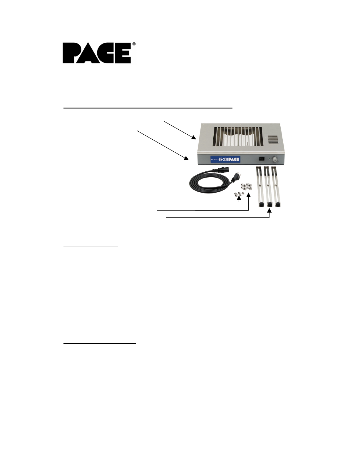
1. Packing Contents (P/N 8007-0343 or 8007-0345)
a. HS 300 Pre-Heater
b. Power Cord
c. 5 PCB Support Pins
d. 4 PCB Holder Pins
e. 3 PCB Support Rails
2. Specification
a. Power: 120 VAC, 60 Hz or 230VAC 50 Hz.
b. Heater Type: Radiant, 400 Watt (200 W x 2), closed loop,
c. Temperature: 212 ºF (100 ºC) – 450 ºF (230 ºC)
Range
d. Dimensions: 13.8” (350 mm) W x 2.5” (62mm) H x 11.6”
e. Weight: 8.8 pounds (4.0 kg)
3. Safety Information
a. Do not contact the Heater or its peripheral parts during operation.
b. Once turned off, let the unit cool completely before contacting.
c. After use, verify that the green LED is off.
d. When using Fluxes, use fume extraction equipment or use in a well
ventilated area to minimize operator exposure to fumes.
thermo-couple control
(295mm) D
Page 2
4. Set-up and Operation
a. Connect the power cord to the power inlet on the HS 300 and then
to an appropriate power supply. See Figure 3.
b. Always use the PCB Support Rails and Holder Pins. When
needed, the Support Pins can be used to prevent the PCB from
warping
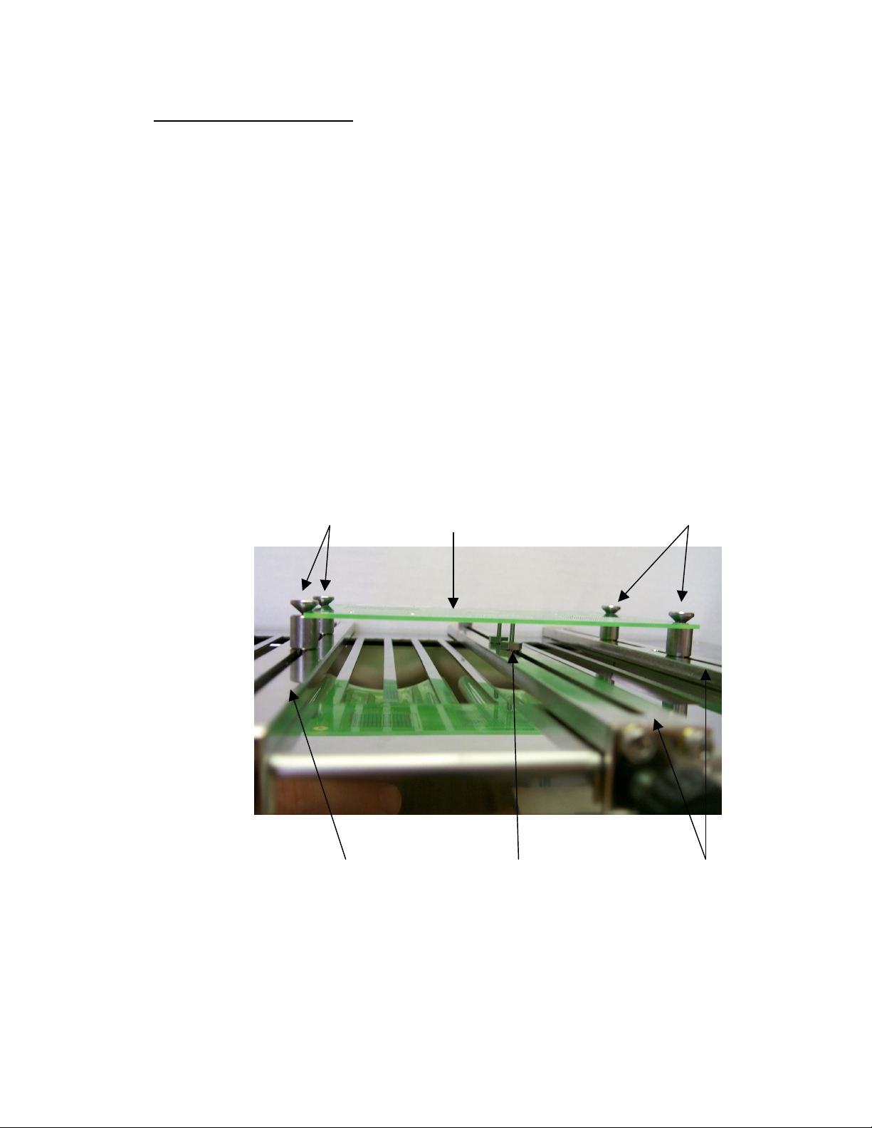
c. Set up of PCB Holder:
i. Use two Support Rails and all Four Holder Pins.
ii. Each Support Rail has two grooves on the back, which are
used to secure the PCB Holder Pins in place.
iii. To affix the PCB Holder Pins to the support rails, first
remove the black nut from the Holder Pins.
iv. Place a black nut into one of the grooves on the back of a
Support Rail. Thread the Holder Pin into the nut from the
other side of the Support Rail.
v. Repeat for each slot on the two Support Rails.
Refer to Figure 2.
HS 300 Pre-Heater Operations Manual
Holder Pins PCB Holder Pins
Support Rail Support Pins Support Rails
Figure 2.
d. Loosen the Black knob on a Support Rail with the Holder Pins
Installed.
Page 2 of 5
Page 3

HS 300 Pre-Heater Operations Manual
e. Place a Support Rail over the top of the HS 300 and make sure the
far end of the Support Rail is placed over the back edge of the HS
300. See Figure 3.
Support Rails
Power Inlet
Temperature
Control Knob
Power Switch
Figure 3.
f. Tighten the black knob on the Support Rail to secure rail to HS 300.
g. To adjust the Support Rail, loosen the black knob and slide the
Support Rails from side to side to match the width of the PCB.
h. The Holder Pins can be adjusted by twisting the pins a quarter turn
and sliding them back to front in their grooves on the Support Rails
until properly positioned.
CAUTION: The Holder Pins will become hot during normal
operation. Use a tool, gloves, or turn unit off and allow to cool
before adjusting Holder Pins.
i. The PCB can be slid into position. See Figure 4.
Figure 4.
Page 3 of 5
Page 4

HS 300 Pre-Heater Operations Manual
j. When working on Large PCBs, the use of the support pins is
strongly recommended to prevent the PCB from warping.
k. To use the Support Pins (Refer to Figure 2):
i. Select the third Support Rail and attach as many Support
Pins as are needed.
ii. Support Pins are installed on the Support Rail in the same
manner as the Holder Pins. See C-iii – C-iv above.
iii. The Support Pins are adjusted in the same way as the
Holder Pins. See H above.
iv. Place the Support Rail fitted with the Support Pins over the
HS 300 between the 2 existing Support Rails as in D-F
above.
v. When Large PCBs are used, a Support Pin may be required
on the edges in between the Holder Pins. It is
recommended to use all 5 support pins when working on
large PCBs. 2 Support Pins between the Holder Pins and
three Pins on the Center Support Rail in the Center of the
PCB.
l. Turn on the Power Switch
m. Set Temperature knob to desired setting. It will take approximately
10 minutes for the radiant heaters to reach their set temperature
and stabilize. Use of a thermo-couple may be required to verify
actual PCB temperatures.
5. Maintenance
a. The HS 300 should be kept clean. If flux is spilled on the heaters,
the HS 300 should be allowed to cool to room temperature and the
heater panels can be wiped off with an appropriate flux cleaner.
Always unplug the HS 300 before removing the cover to clean the
Heater Panels.
b. Should a heater need to be replaced, please order two (2) P/N
6010-0104-P1 from your local PACE Distributor. It is always
recommended to replace the heaters in pairs.
c. To replace the heating panels:
i. Turn off the HS 300 and make sure it is completely cool.
ii. Unplug the HS 300 and disconnect the Power Cord
iii. Remove any installed Support Rails.
iv. Remove the 7 screws from the top of the HS 300.
v. Remove the metal cover.
vi. Locate the connector blocks on either side of the heaters
and remove the clear plastic cover by loosening the 2
screws that secure the cover.
Page 4 of 5
Page 5

HS 300 Pre-Heater Operations Manual
vii. Remove the paper and then remove the two screws securing
the white wires that connect to the Heaters.
viii. Turn the HS 300 over, and remove the screws (4 each) that
secure the heater assemblies to the HS 300.
ix. Lift the heater assemblies from the HS 300.
x. Remove the heater panel from its holder by loosening the 4
screws on the bottom side of the assembly.
xi. Install the new heaters into their holders by sliding the base
of the heater panel into the slot on the holder and tighten the
4 screws on each holder.
xii. Thread the heater wire through the metal housing to the
appropriate terminal block on the sides of the HS 300.
xiii. Turn the unit over and re-install the screws that secure the
heater assemblies to the HS 300 (4 for each heater)
xiv. Turn the HS 300 back over (top up) and secure the white
wires to the terminal block using the screws that were
removed in step vi.
xv. Replace the paper then replace the clear cover and tighten
the cover screws.
xvi. Replace the metal cover
xvii. Replace the 7 cover screws.
xviii. Reconnect to an appropriate power supply
xix. Continue with normal use.
Page 5 of 5
 Loading...