


Contents
Back to overview
Introduction .................................... 2
In brief ............................................ 6
Keys, doors and windows ............ 20
Seats, restraints ........................... 47
Storage ........................................ 67
Instruments and controls ............. 86
Lighting ...................................... 117
Infotainment system ................... 124
Climate control ........................... 127
Driving and operating ................. 135
Vehicle care ............................... 162
Service and maintenance .......... 209
Technical data ........................... 213
Customer information ................ 263
Index .......................................... 266
2 Introduction
Introduction

Introduction 3
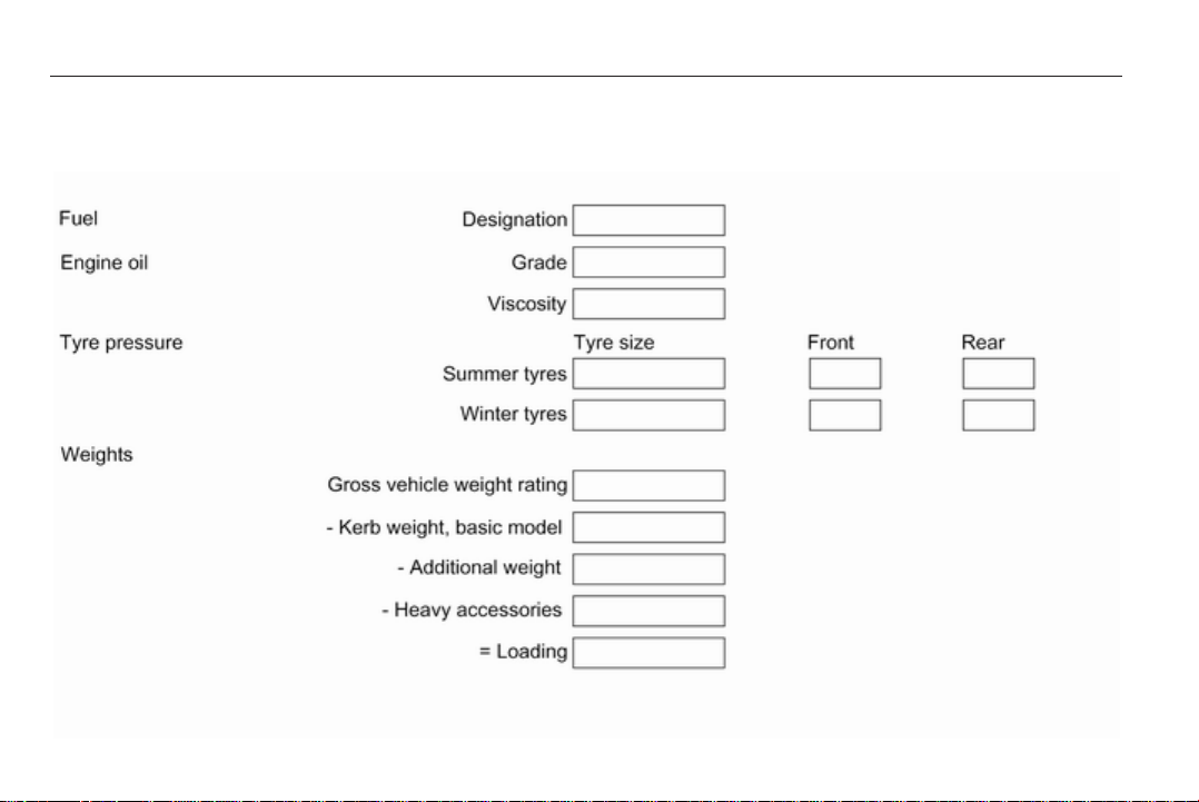
Vehicle specific data
Please enter your vehicle's data on
the previous page to keep it easily
accessible. This information is
available in the sections "Service and
maintenance" and "Technical data"
as well as on the identification plate.
Introduction
Your vehicle is a designed
combination of advanced technology,
safety, environmental friendliness
and economy.
This Owner's Manual provides you
with all the necessary information to
enable you to drive your vehicle
safely and efficiently.
Make sure your passengers are
aware of the possible risk of accident
and injury which may result from
improper use of the vehicle.
You must always comply with the
specific laws and regulations of the
country that you are in. These laws
may differ from the information in this
Owner's Manual.
When this Owner's Manual refers to
a workshop visit, we recommend your
Opel Service Partner.
All Opel Service Partners provide
first-class service at reasonable
prices. Experienced mechanics
trained by Opel work according to
specific Opel instructions.
The customer literature pack should
always be kept ready to hand in the
vehicle.
Using this manual
■ This manual describes all options
and features available for this
model. Certain descriptions,
including those for display and
menu functions, may not apply to
your vehicle due to model variant,
country specifications, special
equipment or accessories.
■ The "In brief" section will give you
an initial overview.
■ The table of contents at the
beginning of this manual and within
each section shows where the
information is located.
■ The index will enable you to search
for specific information.
■ This Owner's Manual depicts lefthand drive vehicles. Operation is
similar for right-hand drive vehicles.
■ The Owner's Manual uses the
factory engine designations. The
corresponding sales designations
can be found in the section
"Technical data".
■ Directional data, e.g. left or right, or
front or back, always relate to the
direction of travel.
■ The vehicle display screens may
not support your specific language.
■ Display messages and interior
labelling are written in bold letters.
Danger, Warnings and
Cautions
9 Danger
Text marked 9 Danger provides
information on risk of fatal injury.
Disregarding this information may
endanger life.

4 Introduction
9 Warning
Text marked 9 Warning provides
information on risk of accident or
injury. Disregarding this
information may lead to injury.
Caution
Text marked Caution provides
information on possible damage to
the vehicle. Disregarding this
information may lead to vehicle
damage.
Symbols
Page references are indicated with 3.
3 means "see page".
We wish you many hours of
pleasurable driving.
Adam Opel AG

Introduction 5
6 In brief
In brief
Initial drive information
Vehicle unlocking
Radio remote control
Press button q to unlock the vehicle.
Open the doors by pulling the
handles.
To open the tailgate, push the
touchpad below the handle.
Saloon 4-door: Press button q on the
remote control for at least 2 seconds,
the boot lid opens slightly.
Radio remote control 3 20, Central
locking system 3 25, Load
compartment 3 28.
Electronic key
When in possession of the electronic
key, simply pulling the door handle
will unlock the vehicle and open the
door. To open the tailgate, press the
button under the moulding.
Open&Start system 3 22.
In brief 7
Seat adjustment
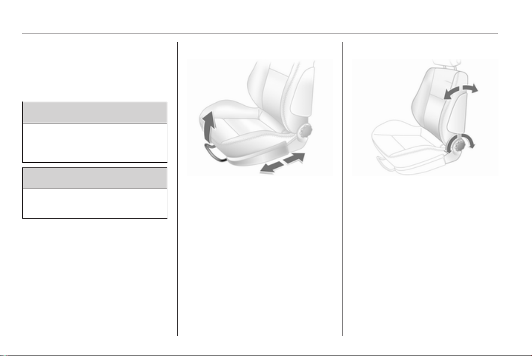
Seat positioning
Pull handle, slide seat, release
handle.
Seat adjustment 3 50, Seat position
3 49.
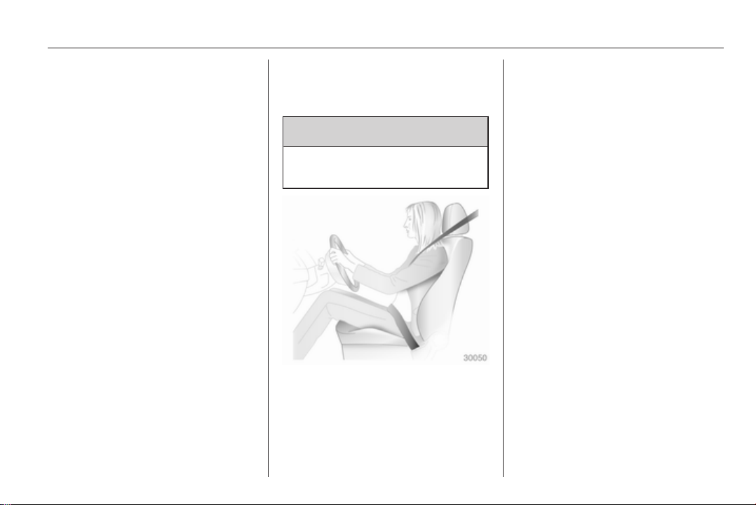
9 Danger
Do not sit nearer than 25 cm from
the steering wheel, to permit safe
airbag deployment.
Seat backrests
Turn handwheel. Do not lean on seat
when adjusting.
Seat adjustment 3 50, Seat position
3 49, Folding front passenger seat
backrest 3 52.
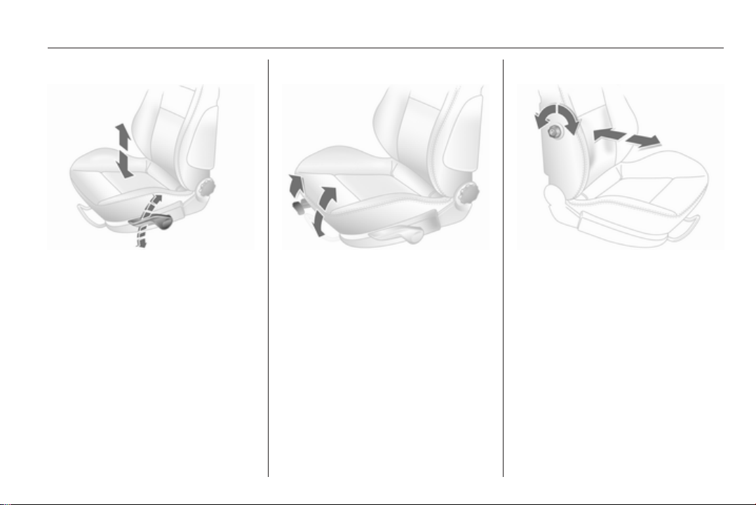
Seat height
Lever pumping motion
up = higher
down = lower
Seat adjustment 3 50, Seat position
3 49.
8 In brief
Seat inclination
Pull lever, adjust inclination by
shifting body weight. Release lever
and audibly engage seat in position.
Seat adjustment 3 50, Seat position
3 49.
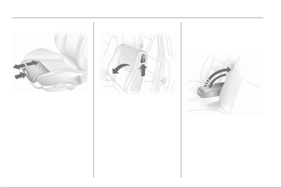
Head restraint adjustment
Press release button, adjust height,
engage.
Head restraints 3 47.
Seat belt
Pull out the seat belt and engage in
belt buckle. The seat belt must not be
twisted and must fit close against the
body. The backrest must not be tilted
back too far (maximum approx. 25 °).
To release belt, press red button on
belt buckle.
Seat belts 3 54, Airbag system
3 57, Seat position 3 49.
In brief 9
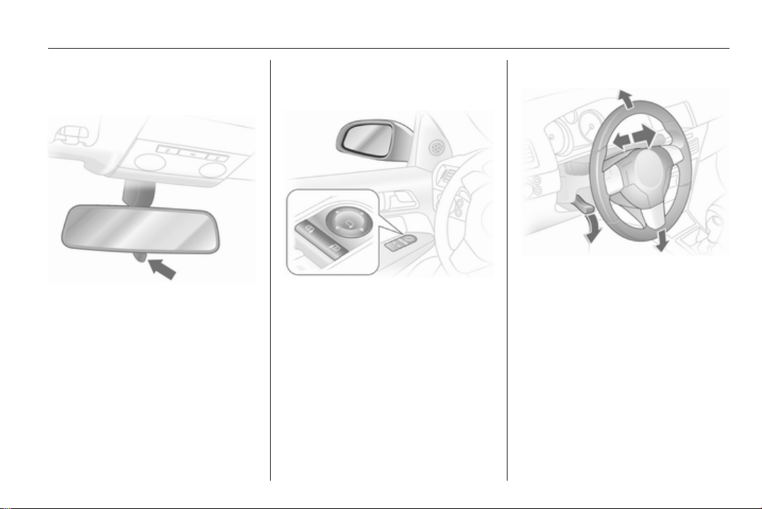
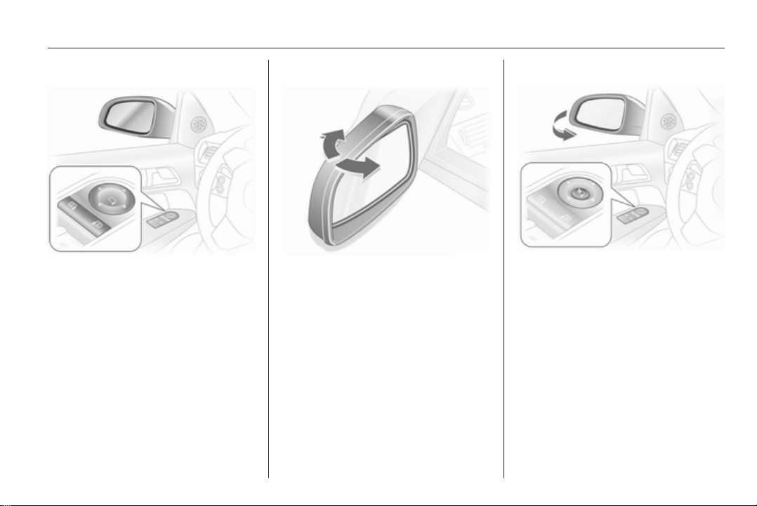
Mirror adjustment
Interior mirror
Swivel the lever on the underside to
reduce dazzle.
Interior mirror 3 34, Automatic antidazzle interior mirror 3 34.
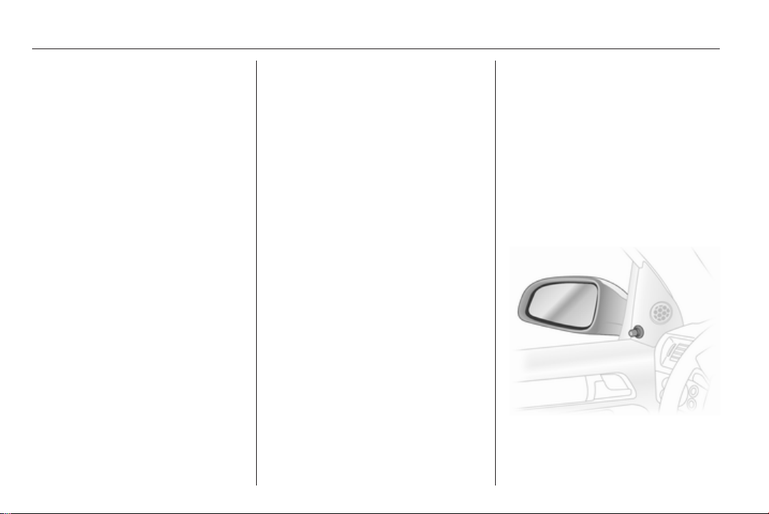
Exterior mirrors
Electric adjustment
Select the relevant exterior mirror and
adjust.
Electric adjustment 3 33, Convex
exterior mirrors 3 32, Folding
exterior mirrors 3 33, Heated
exterior mirrors 3 34.
Steering wheel adjustment
Unlock lever, adjust steering wheel,
then engage lever and ensure it is
fully locked. Do not adjust steering
wheel unless vehicle is stationary and
steering wheel lock has been
released.
Airbag system 3 57, Ignition
positions 3 136.
10 In brief

In brief 11
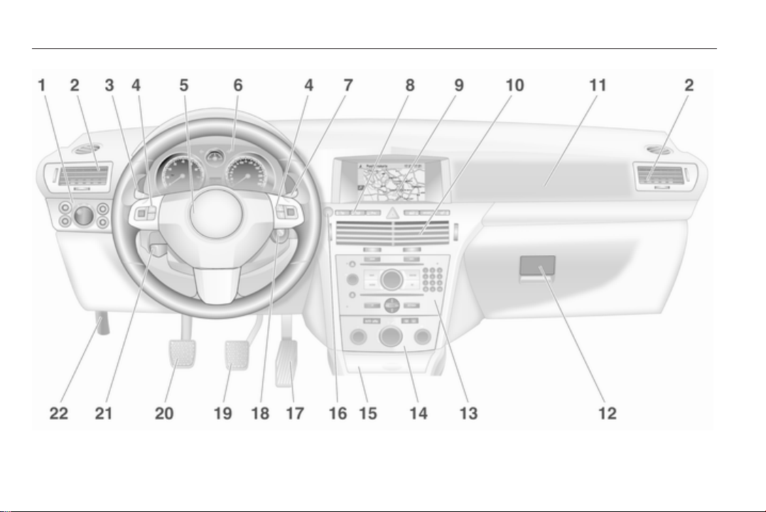
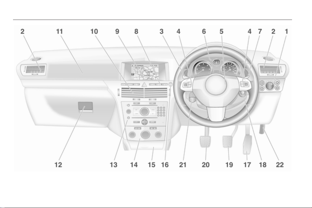
Instrument panel overview
1 Light switch ........................ 117
Instrument illumination ....... 121
Rear fog light ....................... 120
Front fog lights ................... 120
Headlight range
adjustment ......................... 118
2 Side air vents ...................... 133
3 Turn and lane-change
signals, headlight flash,
low beam and high beam ... 120
Exit lighting .......................... 123
Parking lights ...................... 120
Cruise control ..................... 102
4 Steering wheel controls ........ 86
5 Horn ...................................... 87
Driver airbag ......................... 57
6 Instruments .......................... 93
7 Windscreen wiper,
windscreen washer
system, headlight washer
system .................................. 87
8 Left heated seat .................... 53
Deflation detection system ..194
Tyre pressure monitoring
system ................................. 193
Load compartment
unlocking ............................... 28
Ultrasonic parking sensors ... 98
Hazard warning flashers ..... 119
Central locking system .......... 25
Sport mode ........................... 98
Right heated seat .................. 53
9 Info-Display ......................... 102
Trip computer ...................... 112
Electronic climate control
system ................................. 130
10 Centre air vents ................... 133
11 Front passenger airbag ......... 57
12 Glovebox .............................. 67
13 Infotainment system ............ 124
14 Climate control system ........ 127
15 Ashtray .................................. 91
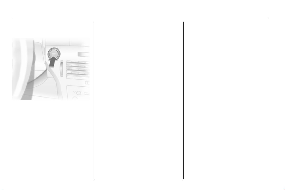
16 Start/Stop button .................. 22
17 Accelerator pedal ................ 135
18 Ignition switch with
steering wheel lock ............. 136
Sensor panel for
emergency operation of
Open&Start system ............... 22
19 Brake pedal ......................... 149
20 Clutch pedal ........................ 135
21 Steering wheel adjustment ...86
22 Bonnet release lever ........... 163
12 In brief
In brief 13
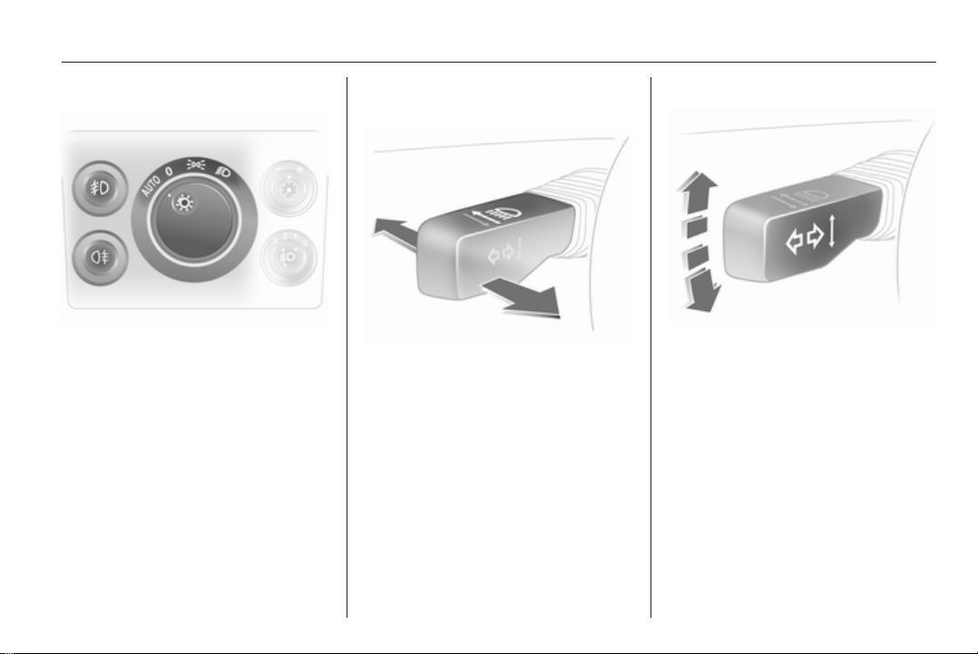
Exterior lighting
Turn light switch
7
8
9
AUTO = Automatic light control
Press light switch
>
r
Lighting 3 117.
= Off
= Sidelights
= Headlights
= Front fog lights
= Rear fog light
Headlight flash, high beam and low beam
Headlight flash = Pull lever
High beam = Push lever
Low beam = Push or pull lever
High beam 3 118, Headlight flash
3 118.
Turn and lane-change signals
To the right = Lever up
To the left = Lever down
Turn and lane-change signals
3 120.
14 In brief
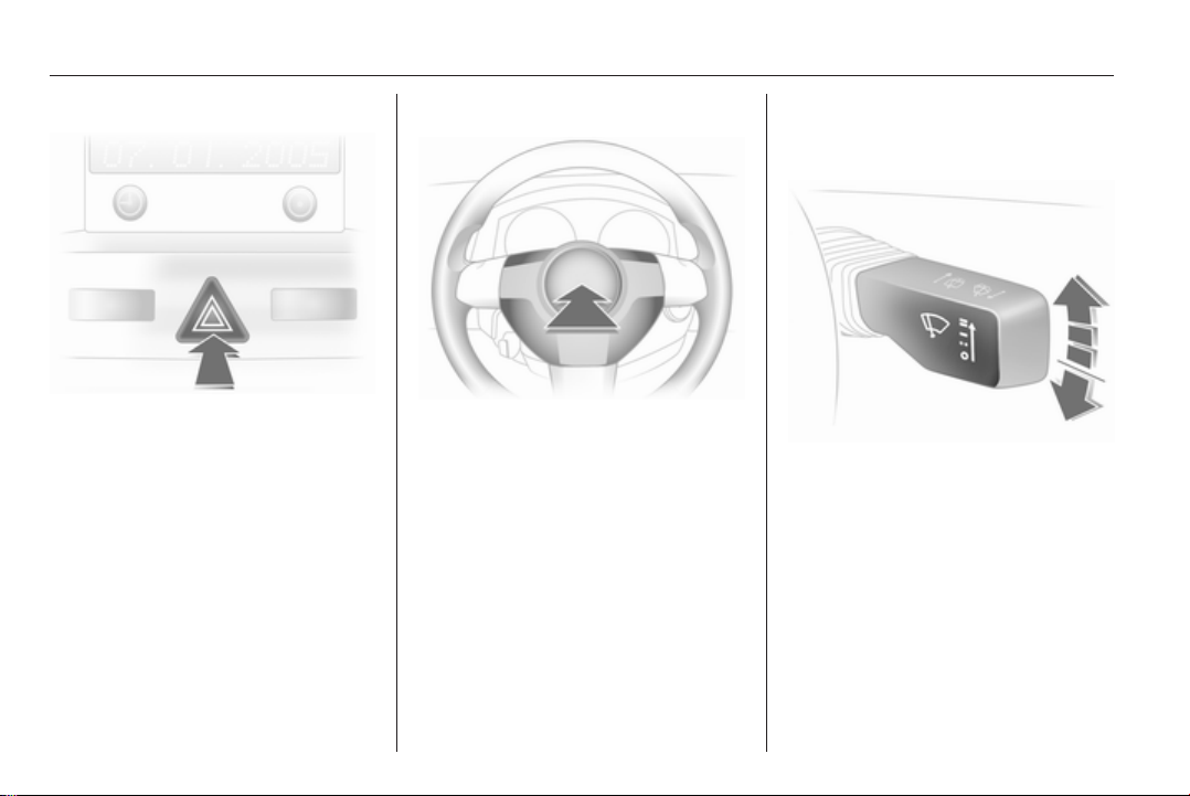
Hazard warning flashers
Operated with the ¨ button.
Hazard warning flashers 3 119.
Horn
Press j.
Washer and wiper systems
Windscreen wiper
= fast
&
= slow
%
= timed interval wipe or
$
automatic wiping with rain
sensor
= off
§
For a single wipe when the
windscreen wiper is off, press the
lever down.
Windscreen wiper 3 87, Wiper
blade replacement 3 167.
In brief 15
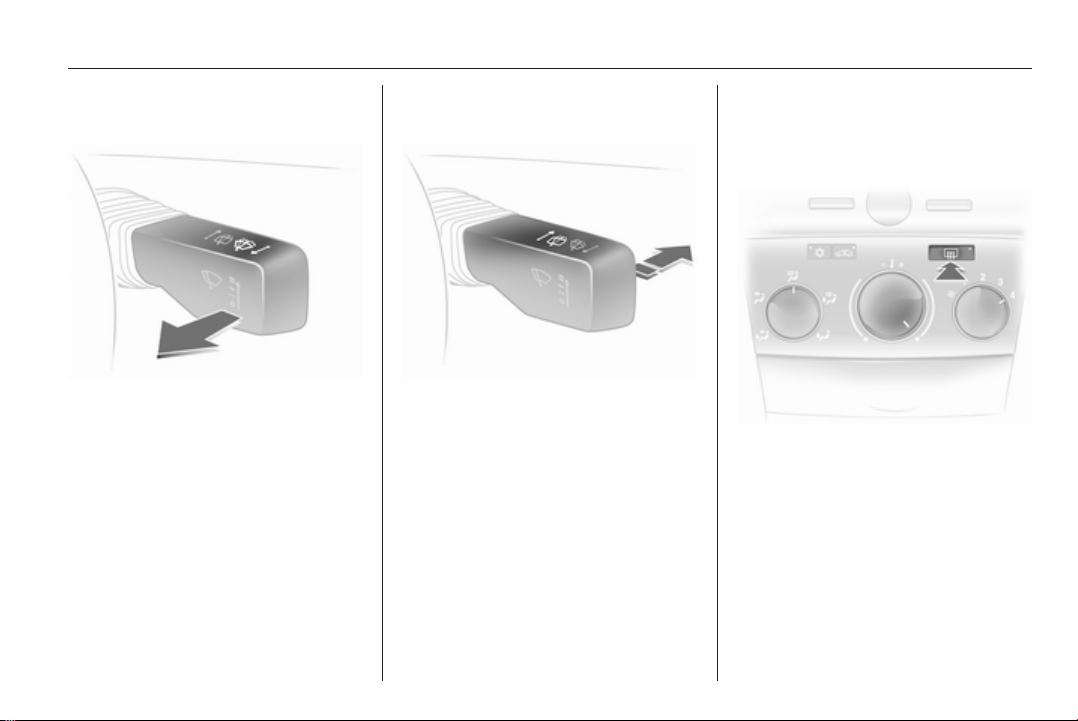
Windscreen and headlight washer systems
Pull lever.
Windscreen and headlight washer
system 3 87, Washer fluid 3 166.
Rear window wiper and washer systems
Wipers on = push lever
Wipers off = push lever again
Wash = push lever and hold
Rear window wipers and washer
system 3 88, Wiper blade
replacement 3 167, Washer fluid
3 166.
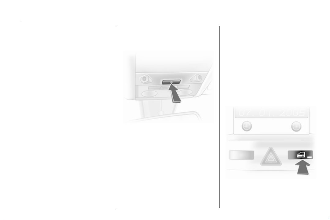
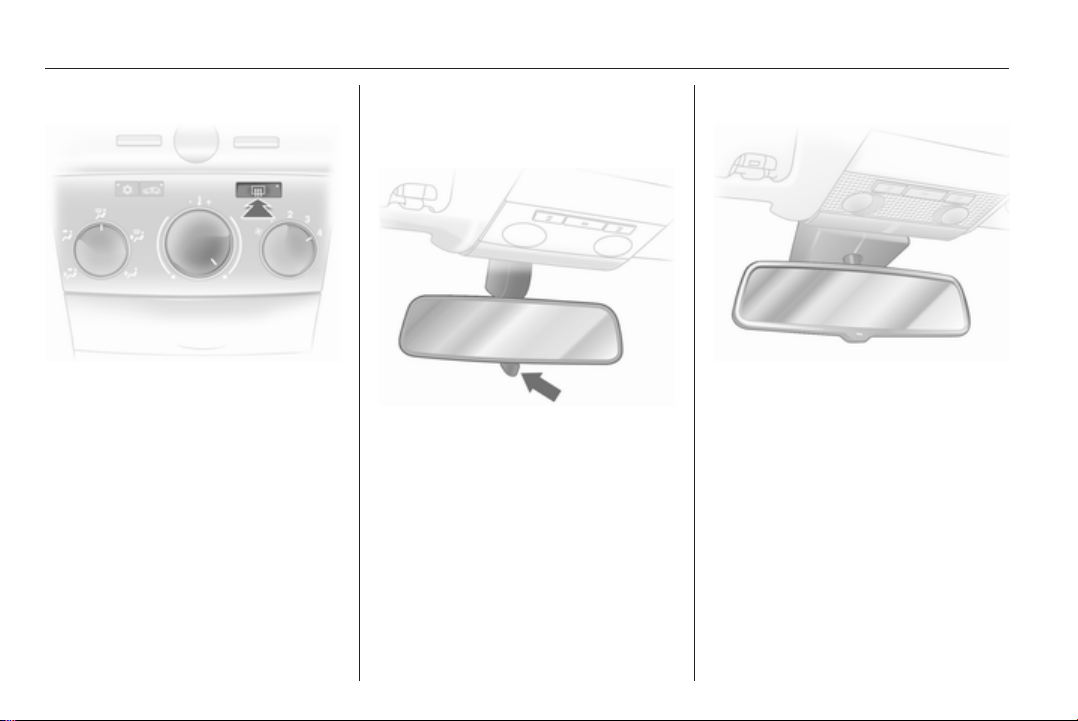
Climate control
Heated rear window, heated exterior mirrors
Heating is operated by pressing the
Ü button.
Heated rear window 3 37.
16 In brief
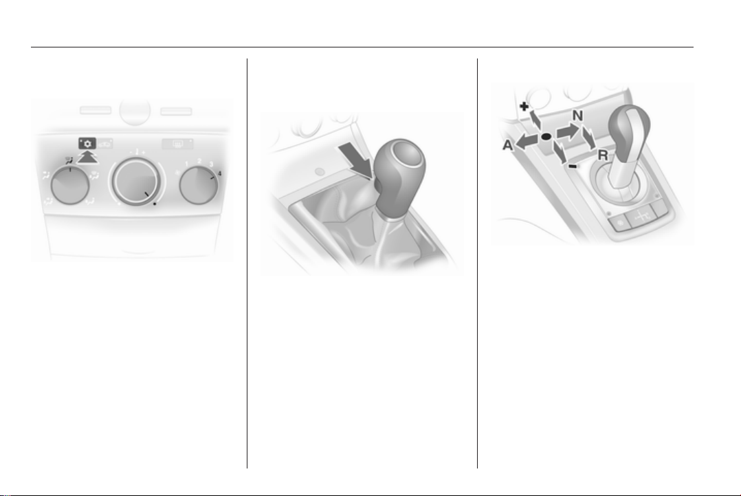
Demisting and defrosting the windows
Air distribution to l.
Set temperature control to warmest
level.
Set fan speed to highest level or to A.
Cooling n on.
Press button V.
Climate control system 3 127.
Transmission
Manual transmission
Reverse: with the vehicle stationary,
wait 3 seconds after depressing
clutch pedal and then pull up the
button on the selector lever and
engage the gear.
If the gear does not engage, set the
lever to neutral, release the clutch
pedal and depress again; then repeat
gear selection.
Manual transmission 3 144.
Manual transmission automated
N = neutral
= drive
o
+ = higher gear
- = lower gear
A = switch between Automatic and
Manual mode
R = reverse gear (with selector
lever lock)
Manual transmission automated
3 145.
In brief 17
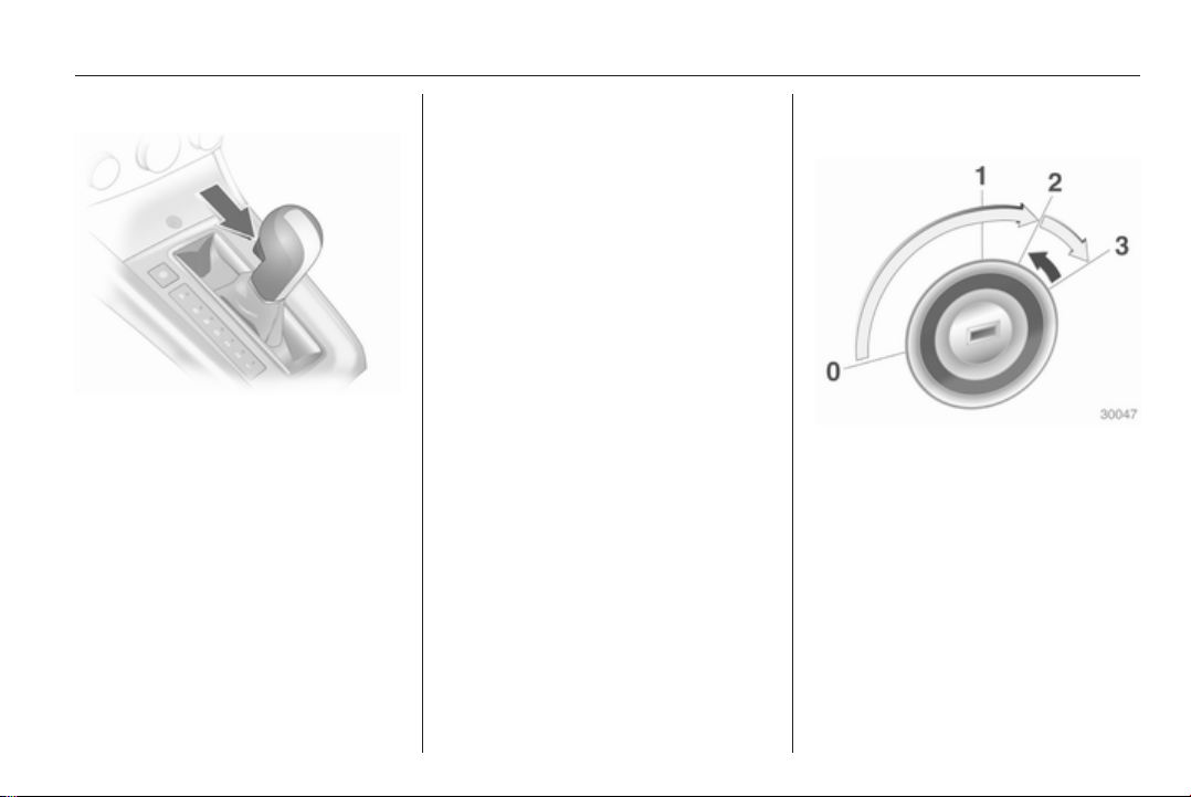
Automatic transmission
P = park
R = reverse
N = neutral
D = drive
The selector lever can only be moved
out of P or N when the ignition is on
and the foot brake is depressed
(selector lever lock). To engage P or
R, push button on selector lever.
The automatic transmission is
available in two versions 3 139.
Starting off
Check before starting off
■ Tyre pressure and condition 3 192,
3 244.
■ Engine oil level and fluid levels
3 164.
■ All windows, mirrors, exterior
lighting and number plates are free
from dirt, snow and ice and are
operational.
■ Proper position of seats, seat belts
and mirrors 3 49, 3 55, 3 33.
■ Brake function at low speed,
particularly if the brakes are wet.
Starting engine with ignition switch
Turn key to position 1. Move the
steering wheel slightly to release the
steering wheel lock. Operate clutch
and brake, automatic transmission in
P or N, do not accelerate; for diesel
engines, turn the key to position 2 for
preheating and wait until control
indicator ! goes out; turn key to
position 3 and release key when
engine is running.
18 In brief
Starting engine with Start/Stop button
The electronic key must be inside the
vehicle. Operate clutch and brake,
automatic transmission in P or N, do
not accelerate, for diesel engines;
press the button briefly to start
preheating, move the steering wheel
slightly to release the steering wheel
lock, wait until control indicator !
goes out and then press button for
1 second and release when the
engine is running.
Open&Start system 3 22.
Parking
■ Always apply the parking brake
without pressing the release button.
Apply as firmly as possible on
a downhill slope or uphill slope.
Depress the foot brake at the same
time to reduce operating force.
■ Switch off the engine. Turn the
ignition key to position 0 and
remove it or, with the vehicle
stationary, press the Start/Stop
button and open the driver's door.
Turn the steering wheel until the
steering wheel lock is felt to
engage.
For vehicles with automatic
transmission, the key can only be
removed when the selector lever is
in the P position. If P is not engaged
or the parking brake is not applied,
"P" flashes for a few seconds in the
transmission display.
■ If the vehicle is on a level surface or
uphill slope, engage first gear or set
the selector lever to P before
switching off the ignition. On an
uphill slope, turn the front wheels
away from the kerb.
If the vehicle is on a downhill slope,
engage reverse gear or set the
selector lever to P before switching
off the ignition. Turn the front
wheels towards the kerb.
■ Lock the vehicle with button p on
the radio remote control or with the
sensor in a front door handle.
To activate the anti-theft locking
system and the anti-theft alarm
system, press button p twice or
touch the sensor in a front door
handle twice.
■ Do not park the vehicle on an easily
ignitable surface. The high
temperature of the exhaust system
could ignite the surface.
■ On vehicles with manual
transmission automated, control
indicator R flashes for a few
seconds after the ignition is
switched off if the parking brake has
not been applied 3 109.
■ Close windows and sunroof or
TwinTop.

■ The engine cooling fans may run
after the engine has been switched
off 3 163.
■ After running at high engine speeds
or with high engine loads, operate
the engine briefly at a low load or
run in neutral for approx.
30 seconds, before switching off in
order to protect the turbocharger.
Keys, locking 3 20, Laying the
vehicle up for a long period of time
3 162, TwinTop roof operation
3 40.
In brief 19
20 Keys, doors and windows
Keys, doors and windows
Keys, locks ................................... 20
Doors ........................................... 28
Vehicle security ............................ 30
Exterior mirrors ............................ 32
Interior mirrors ............................. 34
Windows ...................................... 35
Roof ............................................. 38
Keys, locks
Keys
Replacement keys
The key number is specified in the
Car Pass or on a detachable tag.
The key number must be quoted
when ordering replacement keys as it
is a component of the immobiliser
system.
Locks 3 205, Open&Start system,
electronic key 3 22.
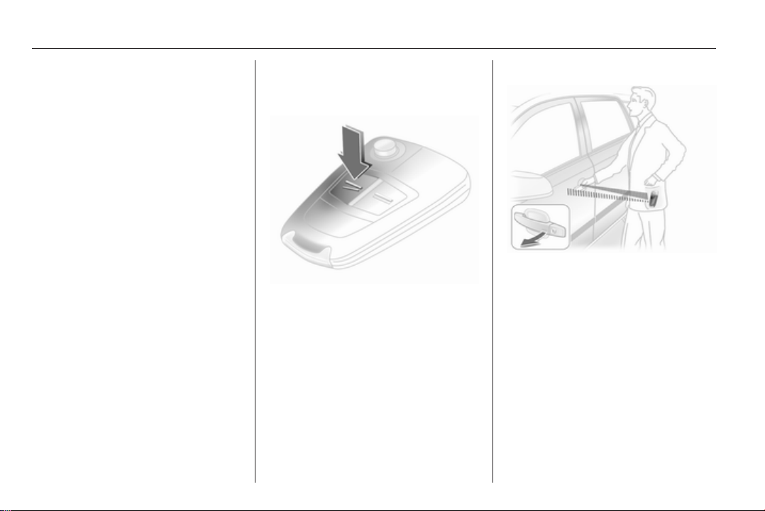
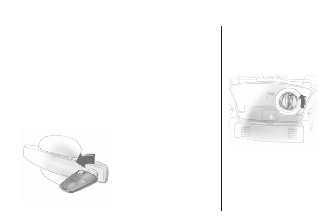
Key with foldaway key section
Press button to extend. To fold the
key, first press the button.
Car Pass
The Car Pass contains security
related vehicle data and should
therefore be kept in a safe place.
When the car is taken to a workshop,
this vehicle data is needed in order to
perform certain operations.
Radio remote control
Keys, doors and windows 21
Used to operate:
■ Central locking system
■ Anti-theft locking system
■ Anti-theft alarm system
■ Power windows
■ Electric roof on Astra TwinTop
The radio remote control has an
approximate range of up to 5 metres.
This range can be affected by outside
influences. The hazard warning
flashers confirm operation.
Handle with care, protect from
moisture and high temperatures and
avoid unnecessary operation.
Fault
If the central locking system cannot
be operated with the radio remote
control, it may be due to the following:
■ Range exceeded
■ Battery voltage too low
■ Frequent, repeated operation of the
radio remote control while not in
range, which will require resynchronisation
■ Overload of the central locking
system by operating at frequent
intervals, the power supply is
interrupted for a short time
■ Interference from higher-power
radio waves from other sources
Unlocking 3 25.
Radio remote control battery replacement
Replace the battery as soon as the
range reduces.
Batteries do not belong in household
waste. They must be disposed of at
an appropriate recycling collection
point.
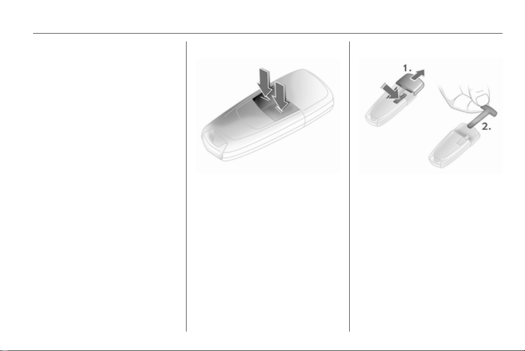
Key with foldaway key section
Extend the key and open the unit.
Replace the battery (battery type
CR 2032), paying attention to the
installation position. Close the unit
and synchronise.
Key with fixed key section
Have the battery replaced by
a workshop.
22 Keys, doors and windows
Radio remote control synchronisation
After replacing the battery, unlock the
door with the key in the driver's door
lock. The radio remote control will be
synchronised when you switch on the
ignition.
Memorised settings
Whenever the key is removed from
the ignition switch, the following
settings are automatically
remembered by the key:
■ Electronic climate control
■ Info-Display
■ Infotainment system
■ Instrument panel illumination
The saved settings are automatically
used next time that key is used for
unlocking.
Open&Start system
Makes operation of the following
possible without the use of the
mechanical key:
■ Central locking system
■ Anti-theft locking system
■ Anti-theft alarm system
■ Power windows
■ Ignition and starter
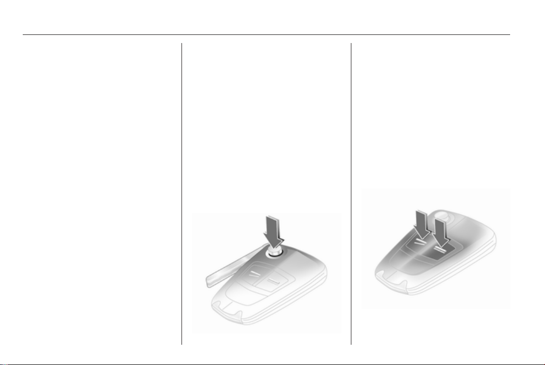
The electronic key simply needs to be
in the driver's possession.
Press the Start/Stop button. The
ignition is switched on. The electronic
immobiliser and steering wheel lock
are deactivated.
To start the engine press and hold the
Start/Stop button whilst applying both
the brake and clutch pedals.
Automatic transmission: the engine
can only be started with the selector
lever in P or N.
The engine and the ignition are
switched off by pressing the Start/
Stop button again. The vehicle must
be stationary. The immobiliser is
activated at the same time.
Keys, doors and windows 23
If the ignition has been switched off
and the vehicle is stationary, the
steering wheel lock activates
automatically when the driver's door
is opened or closed.
Control indicator 0 3 101.
Note
Do not put the electronic key in the
load compartment or in front of the
Info-Display.
The sensor fields in the door handles
must be kept clean to ensure
unrestricted functionality.
If the battery is discharged, the
vehicle must not be towed, towstarted or jump-started as the
steering wheel lock cannot be
disengaged.
Radio remote control
The electronic key likewise has
a radio remote control feature.
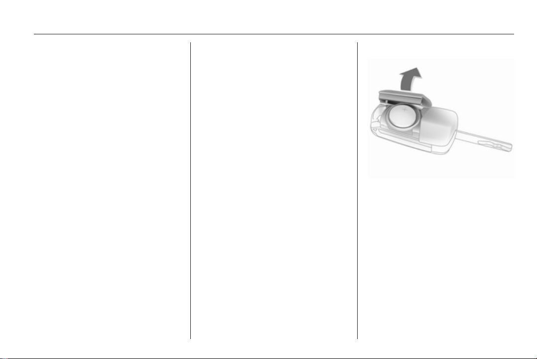
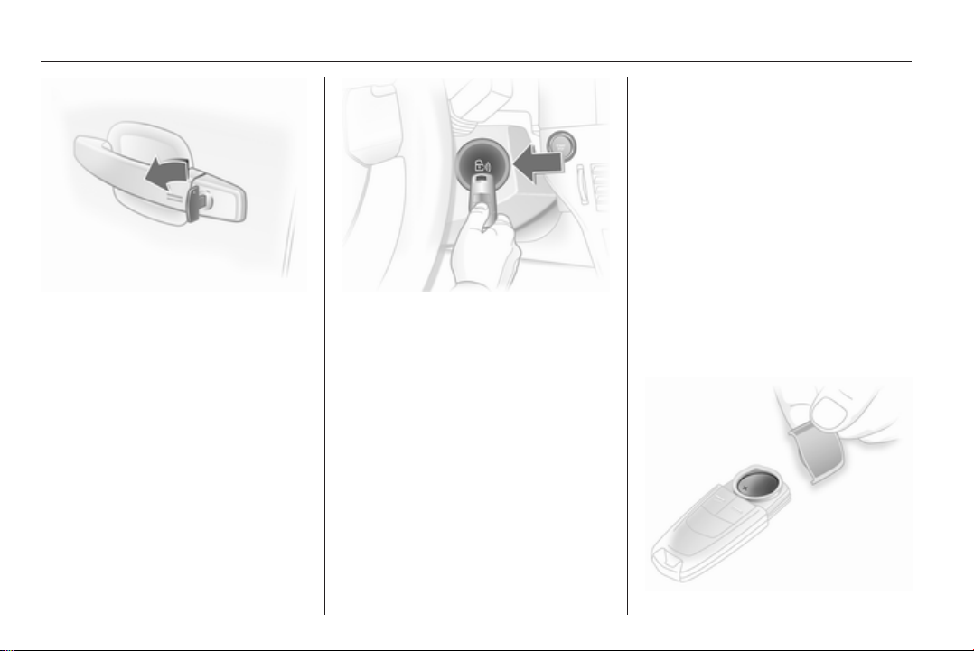
Emergency operation
If the radio remote control also fails,
the driver's door can be locked or
unlocked with the emergency key
contained in the electronic key: press
locking mechanism and remove the
cap by applying light pressure. Push
the emergency key outwards over the
detent and remove.
24 Keys, doors and windows
The emergency key can only lock or
unlock the driver's door. Unlocking
the entire vehicle 3 25. On vehicles
with anti-theft alarm system, the
alarm may be triggered when the
vehicle is unlocked. Deactivate the
alarm by switching on the ignition.
Hold the electronic key at the marked
position and press the Start/Stop
button.
To switch off the engine, press the
Start/Stop button for at least
1 second.
Lock the driver's door with the
emergency key. Locking the entire
vehicle 3 25.
This option is intended for
emergencies only. Seek the
assistance of a workshop.
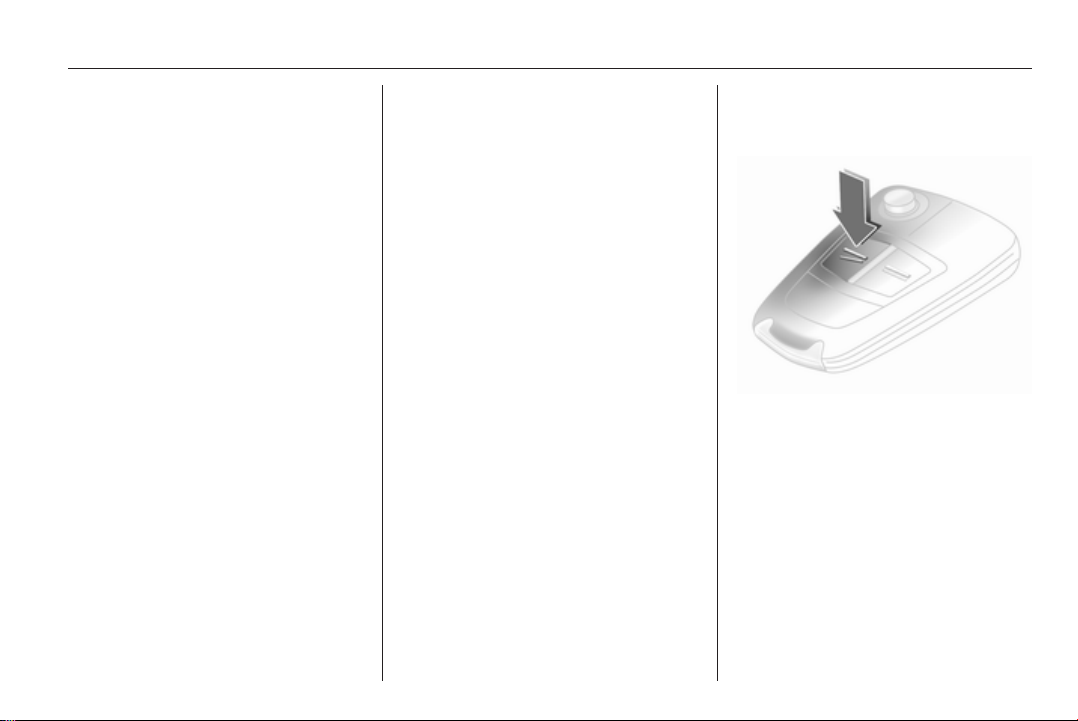
Replacing battery in electronic key
Replace the battery as soon as the
system no longer operates properly
or the range is reduced. The need for
battery replacement is indicated by
InSP3 in the service display or by
a check control message in the
Info-Display.
Service display 3 94, Info-Display
3 110.
Batteries do not belong in household
waste. They must be disposed of at
an appropriate recycling collection
point.
Keys, doors and windows 25
To replace the battery, press the
locking mechanism and remove the
cap by applying light pressure. Press
the cap on the other side outwards.
Replace the battery (battery type
CR 2032), noting the installation
position. Engage caps.
Radio remote control synchronisation
The radio remote control
synchronises itself automatically
during every starting procedure.
Fault
If the central locking cannot be
operated or the engine cannot be
started, the cause may be one of the
following:
■ fault in remote control 3 20
■ electronic key out of reception
range
To rectify the cause of the fault,
change the position of the electronic
key.
Central locking system
Unlocks and locks doors, load
compartment and fuel filler flap.
A pull on an interior door handle
unlocks the entire vehicle and opens
the door.
Note
In the event of an accident of
a certain severity, the vehicle
unlocks automatically.
Note
A short time after unlocking with the
remote control the doors are locked
automatically if no door has been
opened.
Unlocking
Radio remote control
Press button q.
26 Keys, doors and windows
Electronic key
Pull a door handle or press the button
under the tailgate moulding.
The electronic key must be outside
the vehicle, within a range of
approximately 1 metre.
Locking
Close doors, load compartment and
fuel filler flap. If the driver's door is not
closed properly, the central locking
system will not work.
Radio remote control
Press button p.
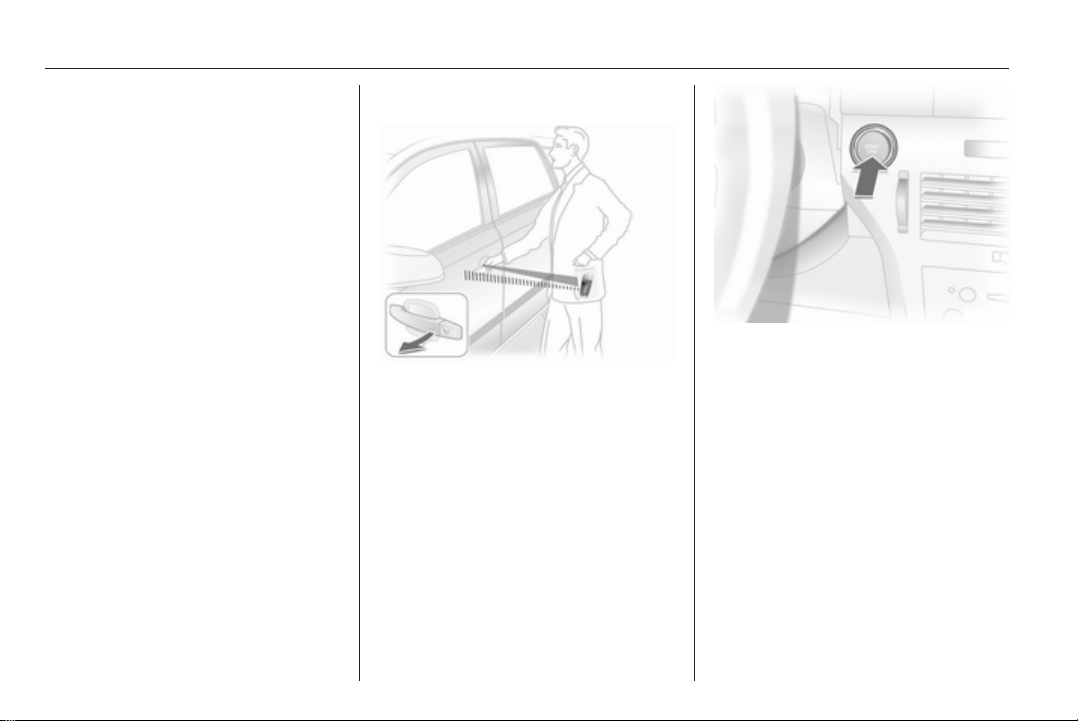
Electronic key
Touch the sensor field in the door
handle of one of the front doors.
The electronic key must be outside
the vehicle, within a range of
approximately 1 metre. The other
electronic key must not be inside the
vehicle.
2 seconds must pass before the
vehicle can be unlocked. Within this
time, it is possible to check that the
vehicle is locked.
Note
The vehicle is not automatically
locked.
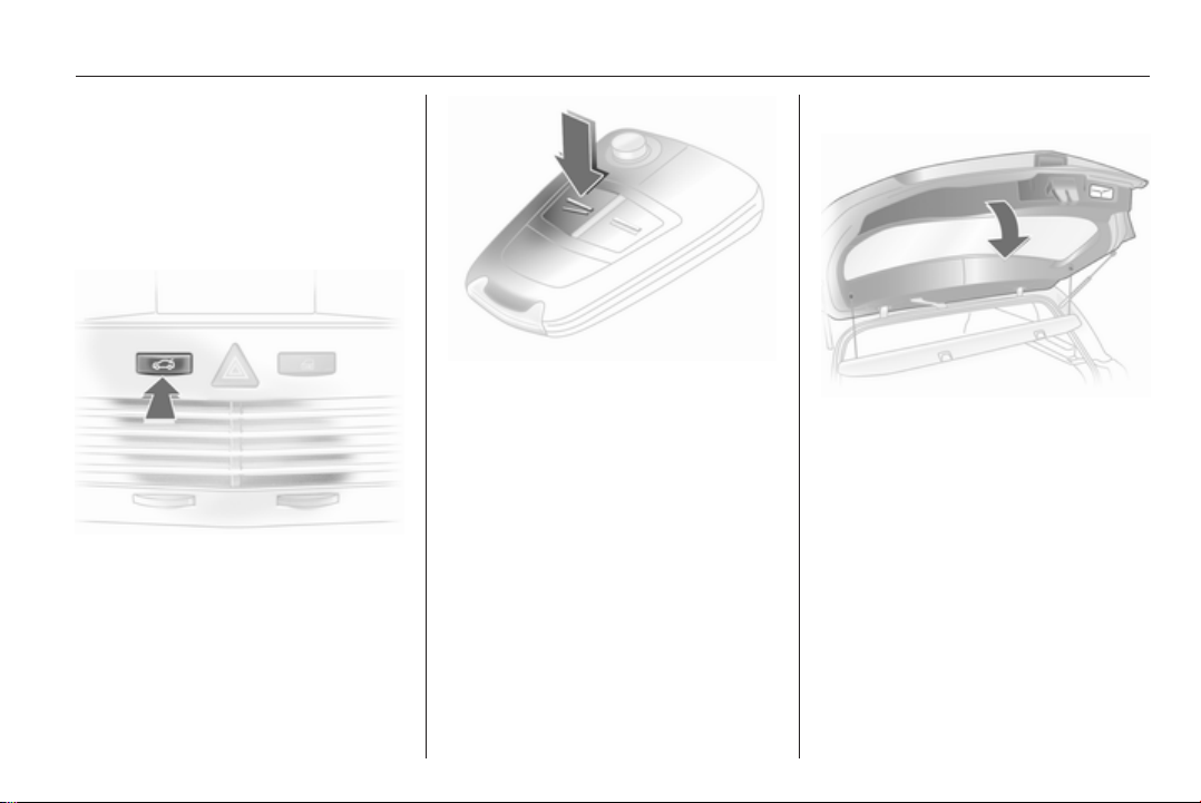
Central locking button
Keys, doors and windows 27
Press the m button: the doors are
locked or unlocked.
The LED in the button m illuminates
for approx. 2 minutes after locking
with the radio remote control.
If the doors are locked from the inside
whilst driving, the LED remains lit.
If the key is in the ignition switch,
locking is only possible if all doors are
closed.
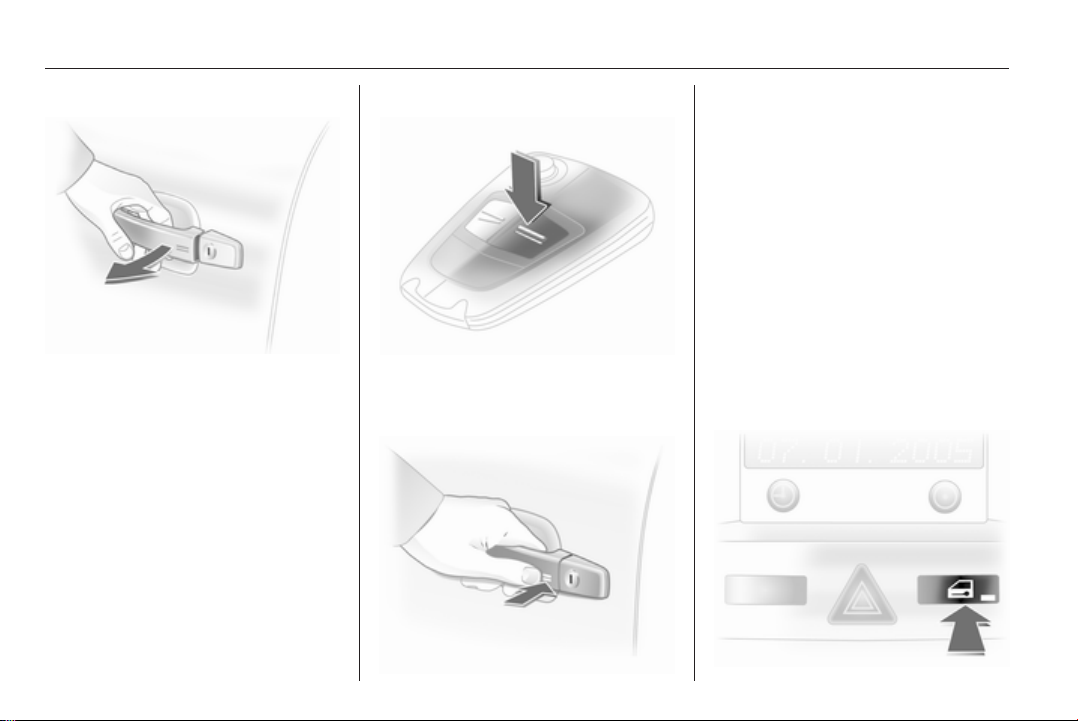
Fault in remote control or Open&Start system
Unlocking
Turn key or emergency key 3 22 in
the driver's door lock as far as it will
go. The entire vehicle is unlocked
when the driver's door is opened.
For Astra TwinTop with open roof after opening the driver's door, press
the central locking button m. The
vehicle will then be unlocked,
provided the anti-theft locking system
is not engaged. Switch on the ignition
to deactivate the anti-theft alarm
system. Open&Start system 3 22.
Locking
Close the driver's door, open the
passenger door, press central locking
button m. The vehicle is locked.
Close the passenger door.
Fault in central locking system
Unlocking
Turn key or emergency key 3 22 in
the driver's door lock as far as it will
go. The other doors can be opened by
using the interior handle (not possible
if the anti-theft locking system is
active). The load compartment and
fuel filler flap remain locked. To
deactivate the anti-theft locking
system, switch on the ignition 3 30.
Manual unlocking of boot lid
Folding the rear seat backrests
3 52.
From the interior, turn the rotary knob
on the inside of the boot lid
anticlockwise, this unlocks the boot
lid and opens it slightly.
28 Keys, doors and windows
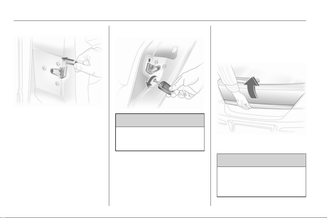
Locking
Insert key or emergency key 3 22 into
opening above lock on inside of door
and operate lock by pressing until it
clicks. Then close the door. The
procedure must be carried out for
each door. The driver's door can also
be locked from the outside with the
key. The fuel filler flap and tailgate/
boot lid cannot be locked.
Child locks
9 Warning
Use the child locks whenever
children are occupying the rear
seats.
Using a key or suitable screwdriver,
turn button on rear door lock to the
horizontal position: door cannot be
opened from inside.
Doors
Load compartment
Opening
Push the button under the tailgate
moulding.
9 Warning
Do not drive with the tailgate open
or ajar, e.g. when transporting
bulky objects, since toxic exhaust
gases could enter the vehicle.
Keys, doors and windows 29
Note
The installation of certain heavy
accessories onto the tailgate may
affect its ability to remain open.
Central locking system 3 25
Saloon 4-door
To unlock the boot lid, press button
x or press button q of the remote
control for at least 2 seconds, the boot
lid is opened slightly.
With the doors centrally locked, the
boot lid cannot be unlocked with
button x.
Closing
Use the interior handle.
Do not press the button under the
moulding while closing as this will
unlock it again.
Close boot lid. The closed boot lid is
always locked. To lock the doors,
press button & on the remote
control.
30 Keys, doors and windows
Vehicle security
Anti-theft locking system
9 Warning
Do not use the system if there are
people in the vehicle! The doors
cannot be unlocked from the
inside.
The system deadlocks all doors. All
doors must be closed or the system
cannot be activated.
If the ignition was on, the driver's door
must be opened and closed once so
that the vehicle can be secured.
Unlocking the vehicle disables the
mechanical anti-theft locking system.
This is not possible with the central
locking button.
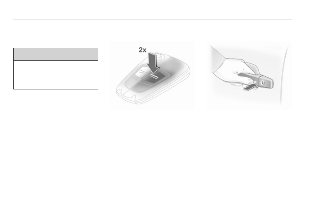
Activating with the radio remote control
Press p twice within 15 seconds.
Activating with the electronic key
Touch the sensor field in the front
door handle twice within 15 seconds.
The electronic key must be outside
the vehicle, within a range of approx.
1 metre.
Anti-theft alarm system
The anti-theft alarm system
incorporates and is operated in
conjunction with the anti-theft locking
system.
Keys, doors and windows 31
It monitors:
■ Doors, load compartment, bonnet,
■ Passenger compartment,
■ Vehicle inclination, e.g. if it is
raised,
■ Ignition.
Unlocking the vehicle deactivates
both systems simultaneously.
Note
Changes to the vehicle interior, such
as the use of seat covers, could
impair the function of passenger
compartment monitoring.
Activation without monitoring of passenger compartment and vehicle inclination
Switch off the monitoring of
passenger compartment and vehicle
inclination, when people or animals
are being left in the vehicle, because
of high volume ultrasonic signals,
movements triggering the alarm and
when the vehicle is on a ferry or train.
1. Close load compartment and
bonnet
2.
Press button b. The LED in button
m flashes for maximum
10 seconds
3. Close doors
4. Activate the anti-theft alarm
system. The LED illuminates.
After approx. 10 seconds, the
system is armed. The LED flashes
until the system is deactivated
For Astra TwinTop, passenger
compartment monitoring is
deactivated if the roof is open to
prevent false alarms.
Light-emitting diode (LED)
32 Keys, doors and windows
During the first 10 seconds of antitheft alarm system activation:
LED
illuminates
LED
flashes
quickly
After the first 10 seconds of anti-theft
alarm system activation:
LED flashes
slowly
LED comes on for
approx. 1 second
Seek the assistance of a workshop in
the event of faults.
= Test, ignition delay
= Door, load
compartment or
bonnet open, or
system fault
= System active
= Switch off
function
Alarm
When triggered, the alarm gives off
an acoustic signal (horn) and a visual
signal (hazard warning flashers). The
number and duration of which are
stipulated by legislation.
The alarm siren can be silenced by
pressing a button of the radio remote
control or by switching on the ignition.
The anti-theft alarm system is
deactivated at the same time.
Immobiliser
The system checks whether the
vehicle is allowed to start with the key
being used. If the transponder in the
key is recognised, the engine can be
started.
The electronic immobiliser activates
itself automatically after the key has
been removed from the ignition
switch or when the engine is switched
off by pressing the Start/Stop button.
Control indicator A 3 97.
Note
The immobiliser does not lock the
doors. You should always lock the
vehicle after leaving it and switch on
the anti-theft alarm system 3 25,
3 30.
Exterior mirrors
Convex shape
The convex exterior mirror contains
an aspherical area and reduces blind
spots. The shape of the mirror makes
objects appear smaller, which will
affect the ability to estimate
distances.
Manual adjustment
Adjust mirrors by swivelling lever in
required direction.
Keys, doors and windows 33
Electric adjustment
First select the relevant exterior mirror
then swivel the control to adjust.
Folding
For pedestrian safety, the exterior
mirrors will swing out of their normal
mounting position if they are struck
with sufficient force. Reposition the
mirror by applying slight pressure to
the mirror housing.
Manual folding
The exterior mirrors can be folded in
by pressing gently on the outer edge
of the housing.
Electric folding
Press the n button and both exterior
mirrors will fold.
Press button n again - both exterior
mirrors return to their original position.
If an electrically folded mirror is
manually extended, pressing the n
button will only electrically extend the
other mirror.
34 Keys, doors and windows
Heated
Operated by pressing the Ü button.
Heating functions with the engine
running and is switched off
automatically after a short time.
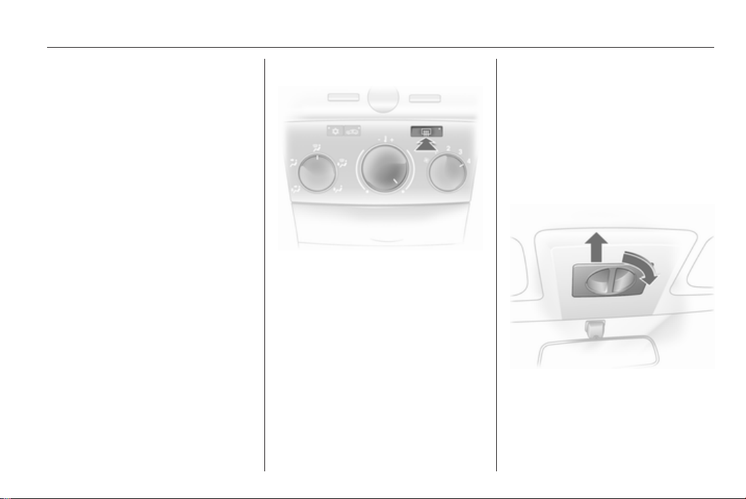
Interior mirrors
Manual anti-dazzle
To reduce dazzle, adjust the lever on
the underside of the mirror housing.
Automatic anti-dazzle
Dazzle from following vehicles at
night is automatically reduced.
Keys, doors and windows 35
Windows
Power windows
9 Warning
Take care when operating the
power windows. Risk of injury,
particularly to children.
If there are children on the rear
seats, switch on the child safety
system for the electric windows.
Keep a close watch on the
windows when closing them.
Ensure that nothing becomes
trapped in them as they move.
Power windows can be operated
■ with ignition on
■ within 5 minutes of switching
ignition off
■ within 5 minutes of switching
ignition key to position 1
After switching off the ignition, the
standby feature ceases when the
driver's door is opened.
Operate the control to open or close
the window.
For vehicles with automatic feature
pull or press the switch again to stop
window movement.
Astra TwinTop: when a door is
opened the window opens slightly
and closes automatically when the
door is closed.
Safety function
If the window glass encounters
resistance above the middle of the
window during automatic closing, it is
immediately stopped and opened
again.
In the event of closing difficulties due
to frost or the like, operate the switch
several times to close the window in
stages.
Central switch for electric windows, Astra TwinTop
$ or " to open or close all
Press
windows.
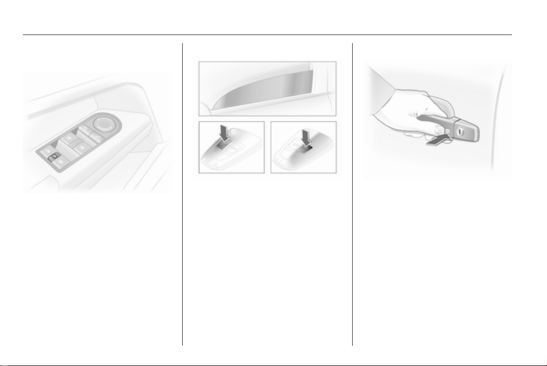
36 Keys, doors and windows
Child safety system for rear windows
Switch z can be used to activate or
deactivate the switches in the rear
doors.
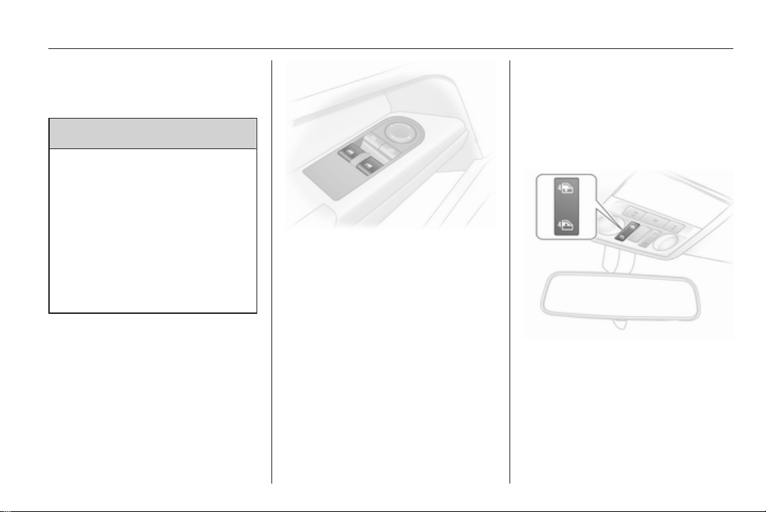
Operating windows from outside
The windows can be operated
remotely from outside the vehicle.
Radio remote control
Press q or p until all windows have
opened or closed.
Open&Start system
To close, touch the sensor field in the
door handle until all windows are
completely closed.
The electronic key must be outside
the vehicle, within a range of approx.
1 metre.
Overload
If the windows are repeatedly
operated within short intervals, the
window operation is disabled for
some time.
Keys, doors and windows 37
Fault
If the windows cannot be opened or
closed automatically, activate the
window electronics as follows:
1. Close doors
2. Switch on ignition
3. Close the window completely and
operate the button for a further
5 seconds
4. Open the window completely and
operate the button for a further
1 second
5. Repeat for each window
Heated rear window
Operated by pressing the Ü button.
Heating functions with the engine
running and is switched off
automatically after a short time.
Astra TwinTop: The heated rear
window and heated exterior mirrors
are deactivated when the roof is
open.
Depending on the engine type, the
heated rear window comes on
automatically when the diesel particle
filter is being cleaned.
Sun visors
The sun visors can be folded down or
swivelled to the side to prevent
dazzling.
If the sun visors have integral mirrors,
the mirror covers should be closed
when driving.
Panoramic windscreen
To open roof lining: Turn handle to the
right and move roof lining rearward to
a suitable position.
38 Keys, doors and windows
To close roof lining: Move forward to
a suitable position. When moved all
the way forward, the roof lining
engages in position.
Note
Close the sun visors before sliding
the roof lining.
Roof
Sunroof
9 Warning
Take care when operating the
sunroof. Risk of injury, particularly
to children.
Keep a close watch on the
movable parts when operating
them. Ensure that nothing
becomes trapped in them as they
move.
Sunroof can be operated with ignition
on.
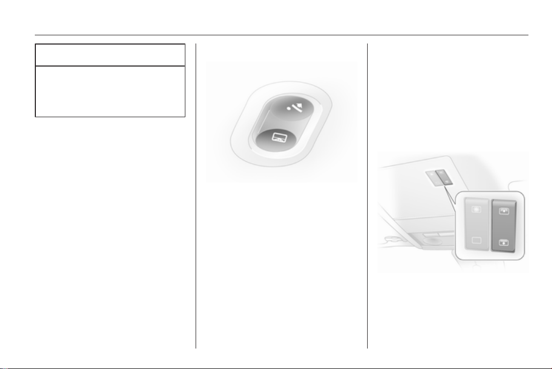
Operated via a rocker switch in the
roof console.
Press the button briefly for activation
in steps. Hold down the button for
longer for automatic opening.
Raise
With the sunroof closed, press ü.
The sunroof is raised at the rear.
Open
Press ü again with the sunroof in the
raised position. The sunroof opens
automatically until it reaches its end
position.
Keys, doors and windows 39
Caution
When using a roof rack, check the
free movement of the sunroof in
order to avoid damage. It is only
permitted to raise the sunroof.
Note
If the top of the roof is wet, tilt
sunroof, allow water to run off and
then open sunroof.
Do not affix any stickers to sunroof.
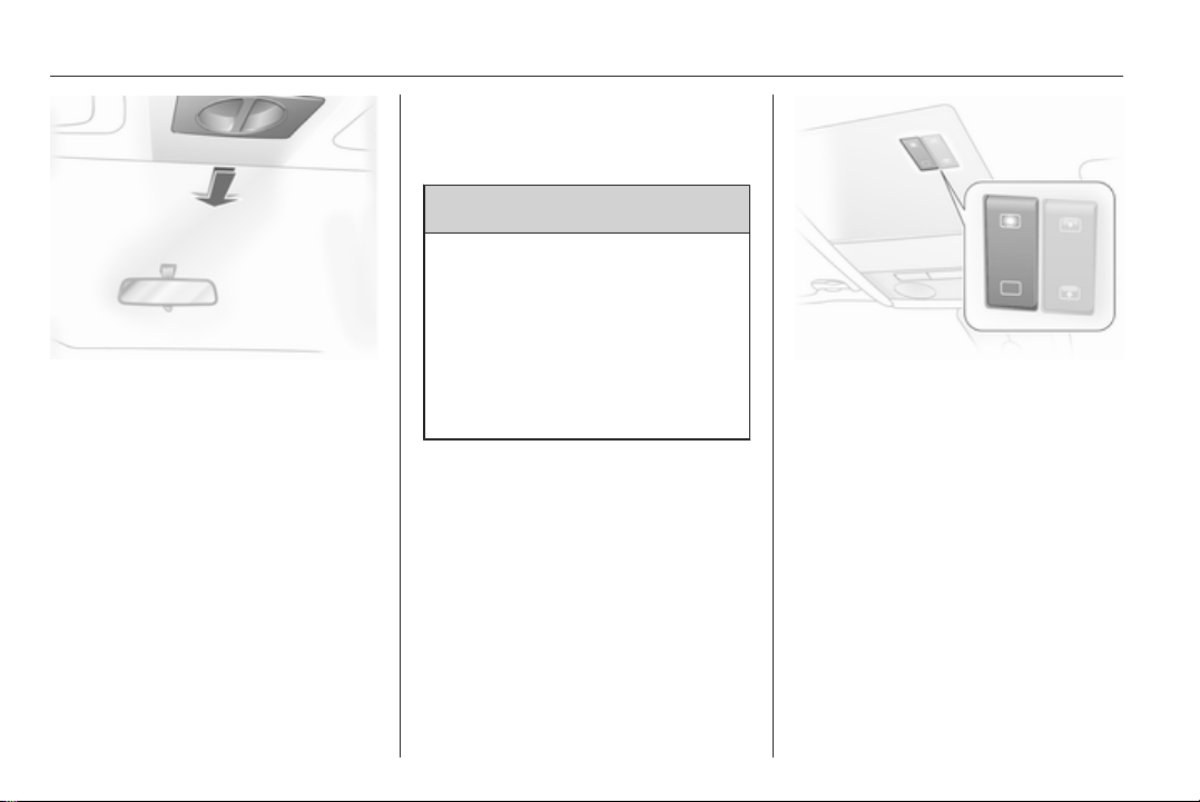
Close
Hold down d until the sunroof is
completely closed.
For safety reasons, the roof closes
from its open position to approx.
20 cm. Hold d depressed to close
completely.
Saloon 4-door
Open
Press l, sunroof opens to comfort
position.
To open beyond comfort position:
press l again.
Close
Press \ until the sunroof is closed.
Raise
When the roof is closed, press \, the
roof is tilted at the rear.
Lowering
Press button l until the sunroof is
closed.
Operating sunroof from outside
Keep button & of the remote control
depressed until the sunroof is fully
closed.
Sunblind
The sunblind is power operated.
The sunblind opens when the sunroof
opens.
Close or open the sunblind by
pressing button H or G.
40 Keys, doors and windows
Hold H depressed to close
completely.
Saloon 4-door
The sunblind is manually operated.
Close or open the sunblind by sliding.
When the sunroof is open, the
sunblind is always open.
Overload
If the system is overloaded, the power
supply is automatically cut off for
a short time.
Initialising the sunroof
If the sunroof and sunblind cannot be
operated (e.g. after disconnecting the
vehicle battery), activate the
electronics as follows:
1. Switch on ignition
2. Close sunroof and hold button
d depressed at least
10 seconds
3. Close sunblind and hold button
H depressed at least
10 seconds
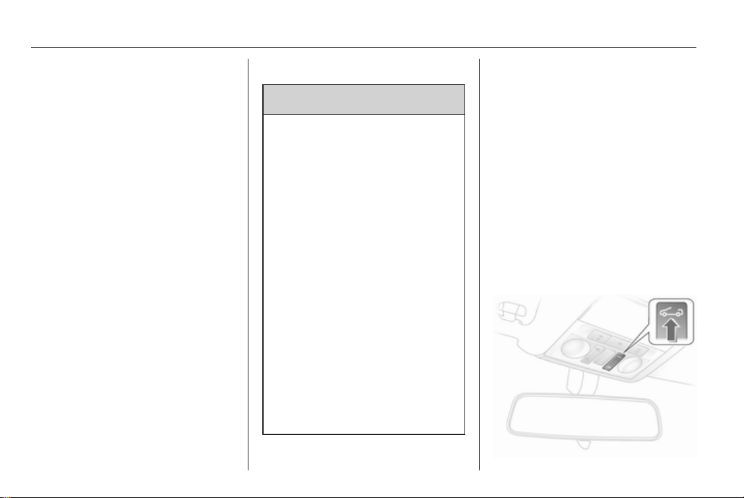
Retractable hardtop
9 Warning
Take care when operating the
convertible hardtop. Risk of injury.
Monitor the action zone above, to
the side and to the rear of the
vehicle during roof operation.
Make sure that nothing could
become pinched. Make sure no
one is in the action zone of the roof
or boot lid during roof operation.
Risk of injury.
Check the amount height, length
and width of available space
before operating the roof, e. g. in
a garage, parking garage or when
a bicycle rack is fitted.
Vehicle passengers should be
informed accordingly.
Before leaving the vehicle, remove
the ignition key in order to prevent
unauthorised operation of the
windows and sunroof.
Stand-by with key in ignition switch
from position 1, or for Open&StartSystem switch on ignition.
Requirements:
■ Vehicle is stationary or driving no
more than 30 km/h
■ Load compartment blind is closed
and engaged 3 73
■ Boot lid is closed
If any of these requirements are not
fulfilled, a warning buzzer sounds
when the switch is actuated and the
roof does not open or close.
Open
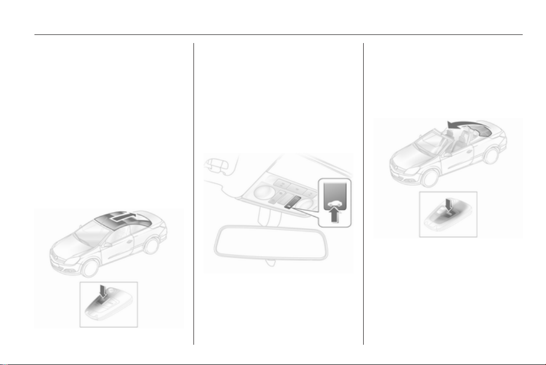
Keys, doors and windows 41
There must be no objects in front of
the rear window or in the pivot area of
the roof and boot lid.
Hold button > in the roof console
depressed until the roof is completely
open and the boot lid is closed.
An acoustic signal sounds at the end
of the opening procedure.
The door windows are opened slightly
before the roof is opened. If button
> is pressed again after the
acoustic signal sounds, the door
windows will close.
Open with remote control
With vehicle stationary unlock the
vehicle. Press button q again and
keep pressed until the roof has
opened fully and the boot lid has
closed.
During operation with the remote
control, the door windows are opened
completely.
Close
Hold button
depressed until the roof and boot lid
are completely closed.
An acoustic signal sounds at the end
of the closing procedure.
< in the roof console
The door windows are opened slightly
before the roof is closed. If button
< is pressed again after the
acoustic signal sounds, the door
windows will close.
Close with remote control
With vehicle stationary, lock the
vehicle. Press button p again and
keep pressed until the roof and boot
lid have closed completely.
Note
■ Do not open the load compartment
until the acoustic signal indicating
the end of the roof opening or
closing procedure has sounded.
42 Keys, doors and windows
■ The load compartment blind must
always be closed during roof
operation.
■ There must be no one and no
objects at the covers behind the
rear head restraints.
■ The roof can only be operated at
temperatures above -20 °C. If the
temperature is below this limit,
a gong will sound three times when
roof operation is requested.
■ Frequent operation of the roof with
the engine off discharges the
battery.
■ Repeated operation of the roof
without breaks can cause
overloading and therefore
malfunctions.
■ The roof can be held in an
intermediate position for 9 minutes
to facilitate cleaning of roof spaces.
This is done by disengaging the
actuation switch. One minute
before the end of this period,
a continuous buzzer sounds as
a warning that the hold period is
almost over and the roof could start
to move.
■ Activating the roof on uneven
ground can lead to malfunctions
and damage.
■ To prevent and remedy squeaking
noises of the roof seals a special
maintenance kit is available at your
service partner. It is recommended
to apply this product once a year for
prevention.
Fault
The automatic drive of the roof is only
operational if the roof is in the proper
open or closed position.
Check if:
■ Load compartment blind is
engaged in closed position
■ Boot lid is completely closed
■ Outside temperature is above
-20 °C
■ There is sufficient battery voltage
■ There is a system overload
If the automatic drive is not
operational, two persons are required
to manually close the roof. See the
accompanying instructions for Astra
TwinTop. Professional assistance is
recommended.
Rollover protection system
The Astra TwinTop is equipped with
rollover protection with reinforced
windscreen frame and anti-roll bars
behind the rear seat head restraints.
Depending on the variant, the anti-roll
bars are either fixed or deploy
automatically in the event of an
impact of a certain severity.
Fixed anti-roll bars
Keys, doors and windows 43
Fixed anti-roll bars are secured to the
vehicle bodywork.
Deployable anti-roll bars
Deployable anti-roll bars are located
between the rear head restraints and
the boot lid. In the event of a rollover,
head-on collision or side impact, the
anti-roll bars deploy upwards within
milliseconds. They also deploy
together with the front and side airbag
systems.
The system deploys with the roof
open or closed.
The convertible roof must not be
operated if the anti-roll bars have
been deployed. A continuous warning
will sound if the switch is actuated.
The airbag control indicator v
illuminates if the anti-roll bars have
been deployed.
Note
Do not place any objects on the
covers of the anti-roll bars behind
the head restraints.
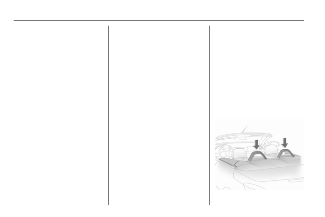
Extended anti-roll bars can be
retracted (e.g. in order to close the
roof after a collision).
Press the lever between the rods of
an anti-roll bar to unlock the system.
Push the anti-roll bar all the way down
until it engages. Fit the cover.
Repeat the procedure on the other
anti-roll bar.
Control indicator v will remain
illuminated and the anti-roll bars will
not deploy in the event of another
collision. Seek the assistance of
a workshop.
9 Warning
The roof cannot be closed or
opened if the anti-roll bars are
extended. The anti-roll bars must
first be retracted.
After deployment of the anti-roll
bar, have the system repaired by
a workshop immediately.
Manually retracted anti-roll bars
will not deploy in the event of
a collision.
Load compartment
44 Keys, doors and windows
The roof can only be opened if the
load in the load compartment does
not exceed the height of the load
compartment blind or protrude
sideways. The load height must not
be exceeded. The load compartment
blind must be flat; objects below it
must not press it upwards. Otherwise
the roof and load may be damaged.
Blockage of boot lid
To avoid damage to the open roof,
boot lid or load, the boot lid can only
be closed if the electric load aid is in
the lower end position 3 77.
Failure of electric drive
Push locking lever forward.
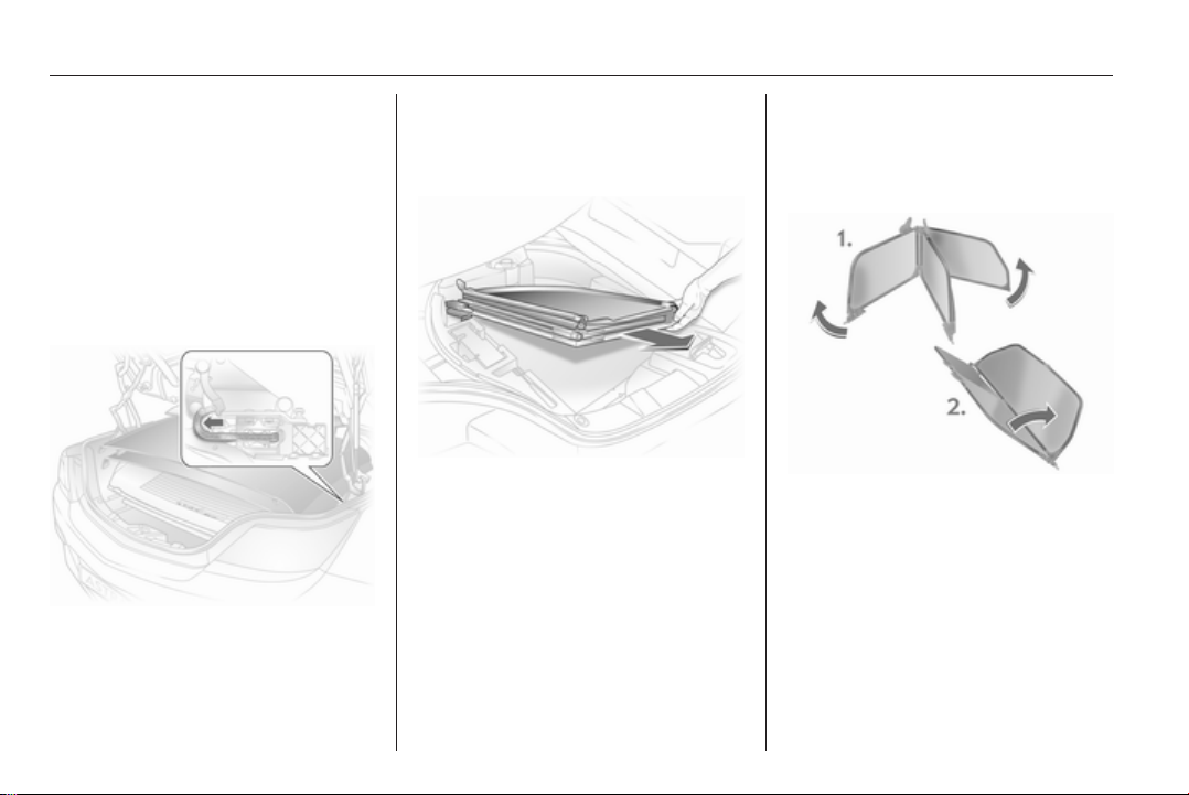
Wind deflector
The rear seats cannot be occupied
when the wind deflector is in place.
Do not place any objects on the wind
deflector.
With tyre repair kit, the wind deflector
is folded down into a storage
compartment in the load
compartment below the loading floor
cover.
For the version with spare wheel, the
wind deflector is folded away in the
load compartment.
Fitting
Expand the collapsed wind deflector.
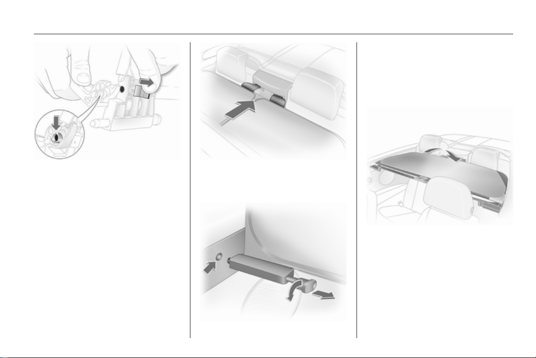
Keys, doors and windows 45
Pull the toggle of the right and left
locking pin and turn to lock.
Straighten out the wind deflector, turn
the toggle back and engage the
locking pin in the recess in the side
trim.
Join together the unfolded ends of the
wind deflector: Press in the pin at the
slider, guide the hinge over the pin
and release the slider so that the pin
engages in the hinge.
Insert the guide clips of the wind
deflector in the seat belt recesses
between the rear head restraints.
The wind deflector can be folded back
when not in use.
If the wind deflector is folded and the
rear seats are unoccupied, the wind
deflector can remain mounted in the
vehicle when the roof is closed.

46 Keys, doors and windows
Removing
Remove in reverse order, wind
deflector is completely folded down in
the load compartment:
■ for tyre repair kit in the
compartment below the loading
floor cover
■ for version with spare wheel , place
in load compartment
The wind deflector must never
protrude upwards or sideways above
the permissible loading height.

Seats, restraints 47
Seats, restraints
Head restraints ............................ 47
Front seats ................................... 49
Rear seats ................................... 53
Seat belts ..................................... 54
Airbag system .............................. 57
Child restraints ............................. 60
Head restraints
Position
9 Warning
Only drive with the head restraint
set to the proper position.
The upper edge of the head restraint
should be at upper head level. If this
is not possible for extremely tall
people, set to highest position, and
set to lowest position for small people.
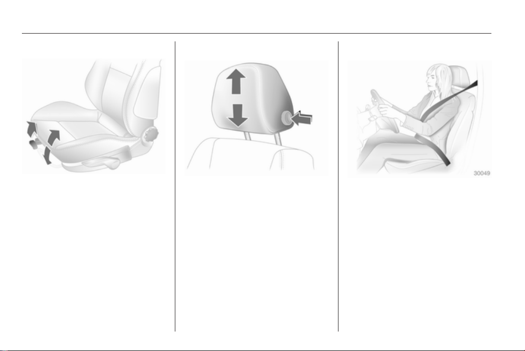
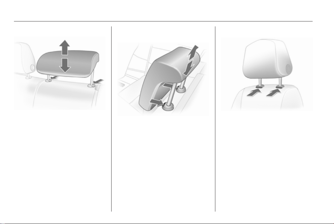
Adjustment
Front and rear outboard head
restraints
Press the button, adjust height and
engage.
48 Seats, restraints
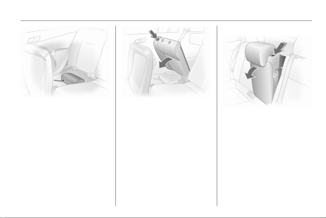
Rear centre head restraint
Pull the head restraint upwards or
press the catch to release and push
the head restraint downwards.
Adjusting the rear head restraints,
Astra TwinTop
Pull the head restraint up or press
both catches to release and then
push the head restraint downwards.
Do not place any objects on the cover
behind the head restraints or between
the head restraints and the anti-roll
bars.
Removing
Press the catches and pull up the
head restraint.
Active head restraints
In the event of a rear-end impact, the
active head restraints tilt slightly
forwards. The head is more
effectively supported so the risk of
whiplash injury is reduced.
Active head restraints are identified
by the lettering ACTIVE on the head
restraint guide sleeves.
Seats, restraints 49
Note
Approved accessories may only be
attached to the front passenger seat
head restraint if the seat is not in use.
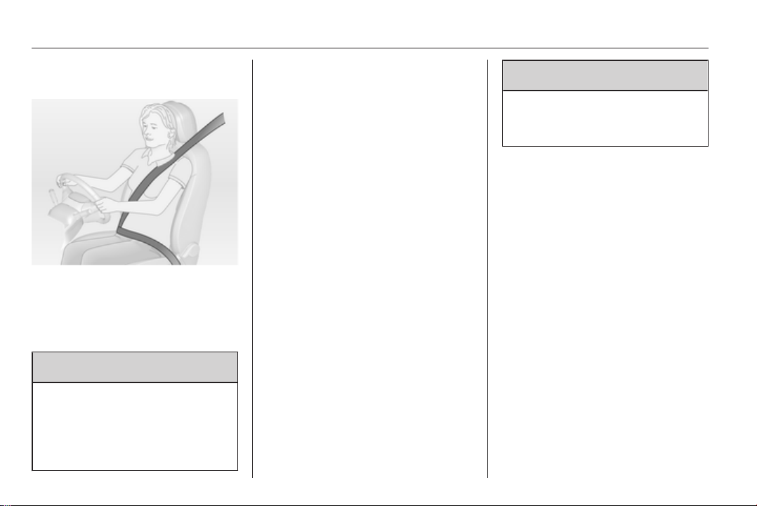
Front seats
Seat position
9 Warning
Only drive with the seat correctly
adjusted.
Sit with buttocks as far back against
■
the backrest as possible. Adjust the
distance between the seat and the
pedals so that legs are slightly
angled when pressing the pedals.
Slide the front passenger seat as
far back as possible.
■ Sit with shoulders as far back
against the backrest as possible.
Set the backrest rake so that it is
possible to easily reach the
steering wheel with arms slightly
bent. Maintain contact between
shoulders and the backrest when
turning the steering wheel. Do not
angle the backrest too far back. We
recommend a maximum rake of
approx. 25°.
■ Adjust the steering wheel 3 86.
■ Set seat height high enough to
have a clear field of vision on all
sides and of all display instruments.
There should be at least one hand
of clearance between head and the
roof frame. Your thighs should rest
lightly on the seat without pressing
into it.
■ Adjust the head restraint 3 47.
■ Adjust the height of the seat belt
3 55.
■ Adjust the thigh support so that
there is a space approx. two fingers
wide between the edge of the seat
and the hollow of the knee.
50 Seats, restraints
■ Adjust the lumbar support so that it
supports the natural shape of the
spine.
Seat adjustment
9 Danger
Do not sit nearer than 25 cm from
the steering wheel, to permit safe
airbag deployment.
9 Warning
Never adjust seats while driving as
they could move uncontrollably.
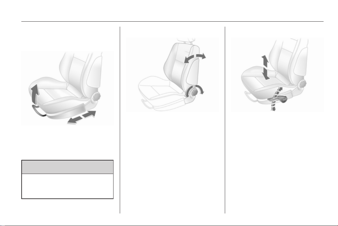
Seat positioning
Pull handle, slide seat, release
handle.
Seat backrests
Turn handwheel. Do not lean on
backrest when adjusting.
Seats, restraints 51
Seat height
Lever pumping motion
up = seat higher
down = seat lower
Seat inclination
Pull lever, adjust inclination by
shifting body weight. Release lever
and audibly engage seat in position.
Lumbar support
Turn handwheel. Do not lean on
backrest when adjusting.
52 Seats, restraints
Adjustable thigh support
Press the button and slide the thigh
support.
Seat folding
Lift release lever and fold backrest
forwards. Slide seat forwards.
To restore, slide the seat backwards.
If the seat has a memory function it
engages in its original position,
otherwise engage seat in desired
position. Move the backrest back to
upright and engage.
Folding the backrest forwards is only
possible when the backrest is in an
upright position.
Do not operate handwheel to adjust
backrest with backrest tilted forward.
In vehicles with a panoramic window:
to tilt seats forward, push head
restraints down and lift up sun visors.
Armrest
Push raised armrest backward
against resistance and fold down.
The armrest can be moved to
different positions in stages by lifting
it.
Under the armrest there is a storage
compartment.
Seats, restraints 53
Heating
Adjust heating to the desired setting
by pressing the ß button for the
respective seat one or more times
with the ignition on. The control
indicator in the button indicates the
setting.
Prolonged use of the highest setting
for people with sensitive skin is not
recommended.
Seat heating is operational when the
engine is running.
Rear seats
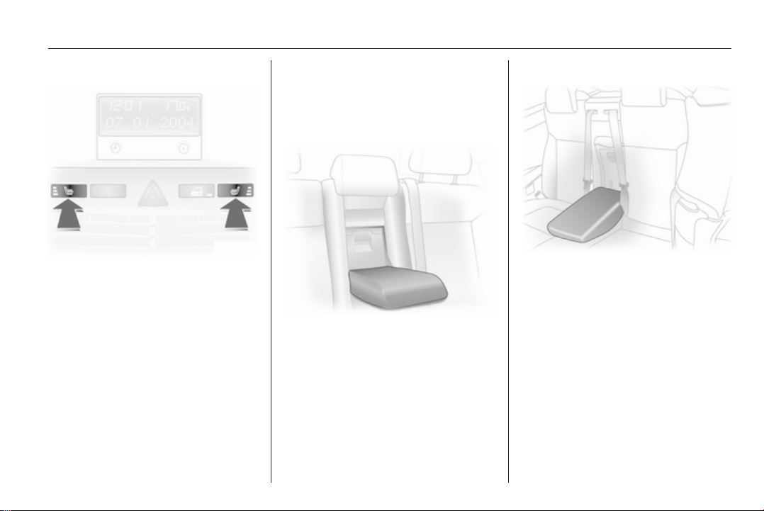
Armrest
Saloon and Station wagon
Fold down the armrest, pulling the
strap obliquely down (45°).
TwinTop
Pull the armrest by the strap, pivot it
down and position on the sit with the
flat side up.
The armrest is held in place on the
backrest with a retaining strap. To
fully remove the armrest, disengage
the bracket at the retaining strap.
54 Seats, restraints
Seat belts
The seat belts are locked during
heavy acceleration or deceleration of
the vehicle holding the occupants in
the sitting position. Thereby the risk of
injury is considerably reduced.
9 Warning
Fasten seat belt before each trip.
In the event of an accident, people
not wearing seat belts endanger
their fellow occupants and
themselves.
Seat belts are designed to be used by
only one person at a time. They are
not suitable for people smaller than
150 cm. Child restraint system
3 60.
Periodically check all parts of the belt
system for damage and proper
functionality.
Have damaged components
replaced. After an accident, have the
belts and triggered belt pretensioners
replaced by a workshop.
Note
Make sure that the belts are not
damaged by shoes or sharp-edged
objects or trapped. Prevent dirt from
getting into the belt retractors.
Seat belt reminder X 3 96.
Belt force limiters
Stress on the body is reduced by the
gradual release of the belt during
a collision.
Belt pretensioners
In the event of a head-on or rear-end
collision of a certain severity, the front
seat belts are tightened.
9 Warning
Incorrect handling (e.g. removal or
fitting of belts) can trigger the belt
pretensioners.
Deployment of the belt pretensioners
is indicated by continuous illumination
of control indicator v 3 96.
Triggered belt pretensioners must be
replaced by a workshop. Belt
pretensioners can only be triggered
once.
Note
Do not affix or install accessories or
other objects that may interfere with
the operation of the belt
pretensioners. Do not make any
modifications to belt pretensioner
components as this will invalidate
the vehicle type approval.
Seats, restraints 55
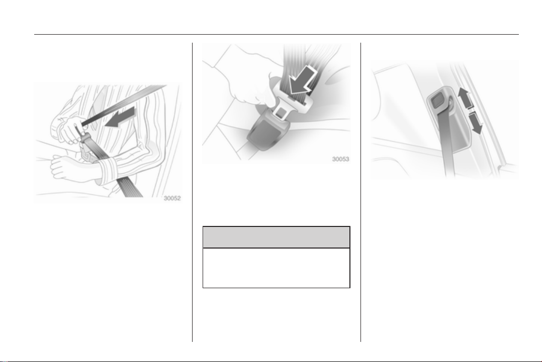
Three-point seat belt
Fastening seat belt
Withdraw the belt from the retractor,
guide it untwisted across the body
and insert the latch plate into the
buckle. Tighten the lap belt regularly
whilst driving by pulling the shoulder
belt.
Seat belt reminder 3 96.
Loose or bulky clothing prevents the
belt from fitting snugly. Do not place
objects such as handbags or mobile
phones between the belt and your
body.
9 Warning
The belt must not rest against hard
or fragile objects in the pockets of
your clothing.
Height adjustment
1. Pull belt out slightly.
2. Press button.
3. Adjust height and engage.
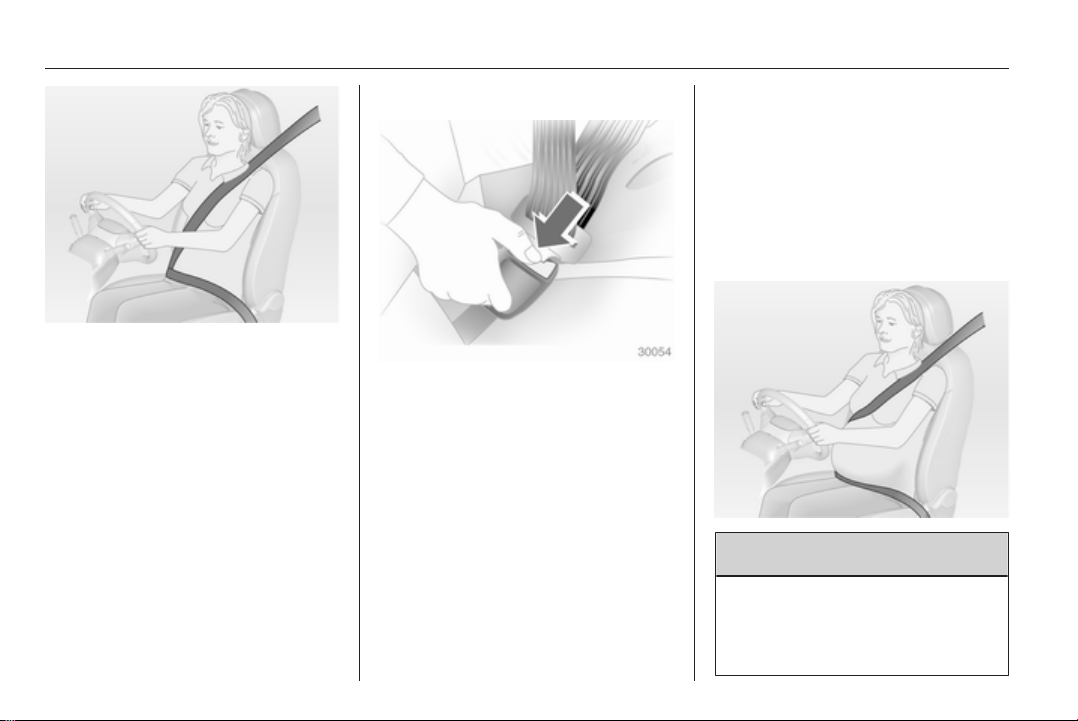
56 Seats, restraints
Adjust the height so that the belt lies
across the shoulder. It must not lie
across the throat or upper arm.
Do not adjust while driving.
Removing seat belt
To release belt, press red button on
belt buckle.
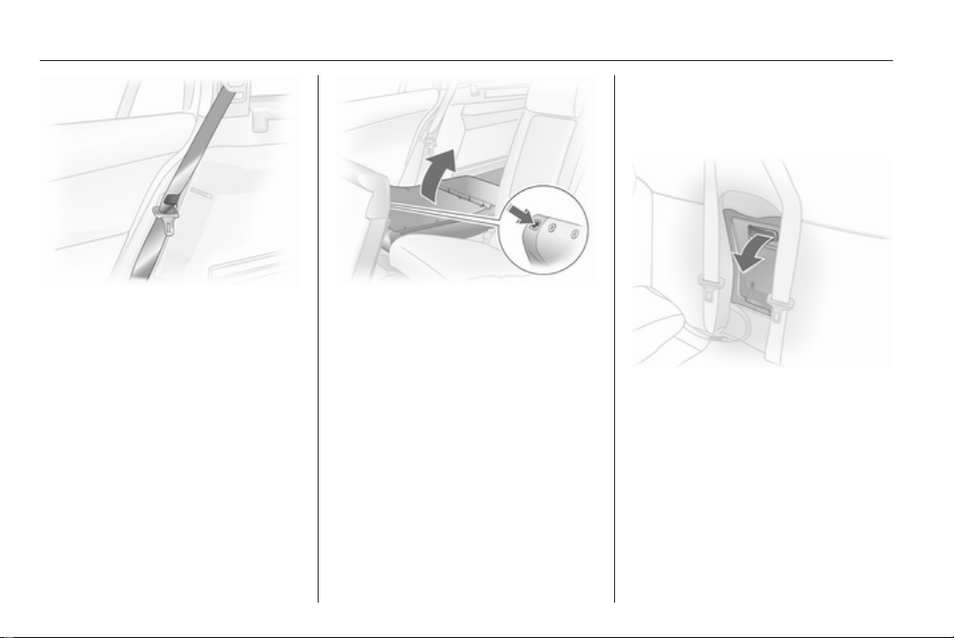
Seat belts on rear seats
Lead seat belts of the outer seats
through holders at the side if they are
not being used.
The seat belt for the middle seat can
only be withdrawn from the retractor if
the backrests are upright and are
engaged in their retainers.
TwinTop
To prevent the seat belts from making
flapping noise when the sun roof and/
or the windows are open, the seat
belts of unoccupied rear seats can be
secured behind the armrest.
Using the seat belt while pregnant
9 Warning
The lap belt must be positioned as
low as possible across the pelvis
to prevent pressure on the
abdomen.
Seats, restraints 57
Airbag system
The airbag system consists of
a number of individual systems
depending on the scope of
equipment.
When triggered the airbag inflates
within milliseconds. They also deflate
so quickly that it is often unnoticeable
during the collision.
9 Warning
If handled improperly the airbag
systems can be triggered in an
explosive manner.
Note
The control electronics of the airbag
systems, belt pretensioners and
deployable anti-roll bars are located
in the centre console area. Do not
put any magnetic objects in this
area.
Do not stick anything on the airbag
covers and do not cover them with
other materials.
Each airbag/anti-roll bar is triggered
only once. Have deployed airbags/
anti-roll bars replaced by
a workshop. Furthermore, it might be
necessary to have the steering
wheel, the instrument panel, parts of
the panelling, the door seals,
handles and the seats replaced.
Do not make any modifications to
the airbag system/anti-roll bars as
this will invalidate the vehicle type
approval.
When the airbags inflate, escaping
hot gases may cause burns.
Control indicator v for airbag systems
and anti-roll bars 3 96.
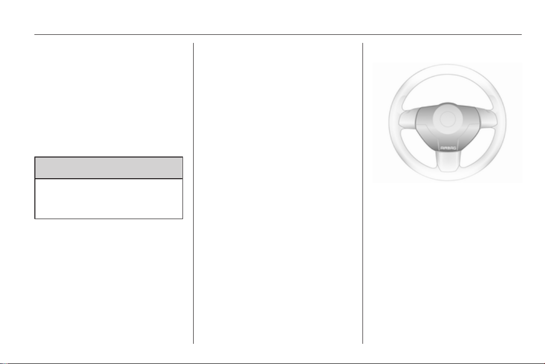
Front airbag system
The front airbag system consists of
one airbag in the steering wheel and
one in the instrument panel on the
front passenger side. These can be
identified by the word AIRBAG.
58 Seats, restraints
Fit the seat belt correctly and
engage securely. Only then the
airbag is able to protect.
Side airbag system
There is also a warning label on the
side of the instrument panel, visible
when the front passenger door is
open.
The front airbag system is triggered in
the event of a front-end impact of
a certain severity. The ignition needs
to be switched on.
The inflated airbags cushion the
impact, thereby reducing the risk of
injury to the upper body and head of
the front seat occupants
considerably.
9 Warning
Optimum protection is only
provided when the seat is in the
proper position 3 49.
Keep the area in which the airbag
inflates clear of obstructions.
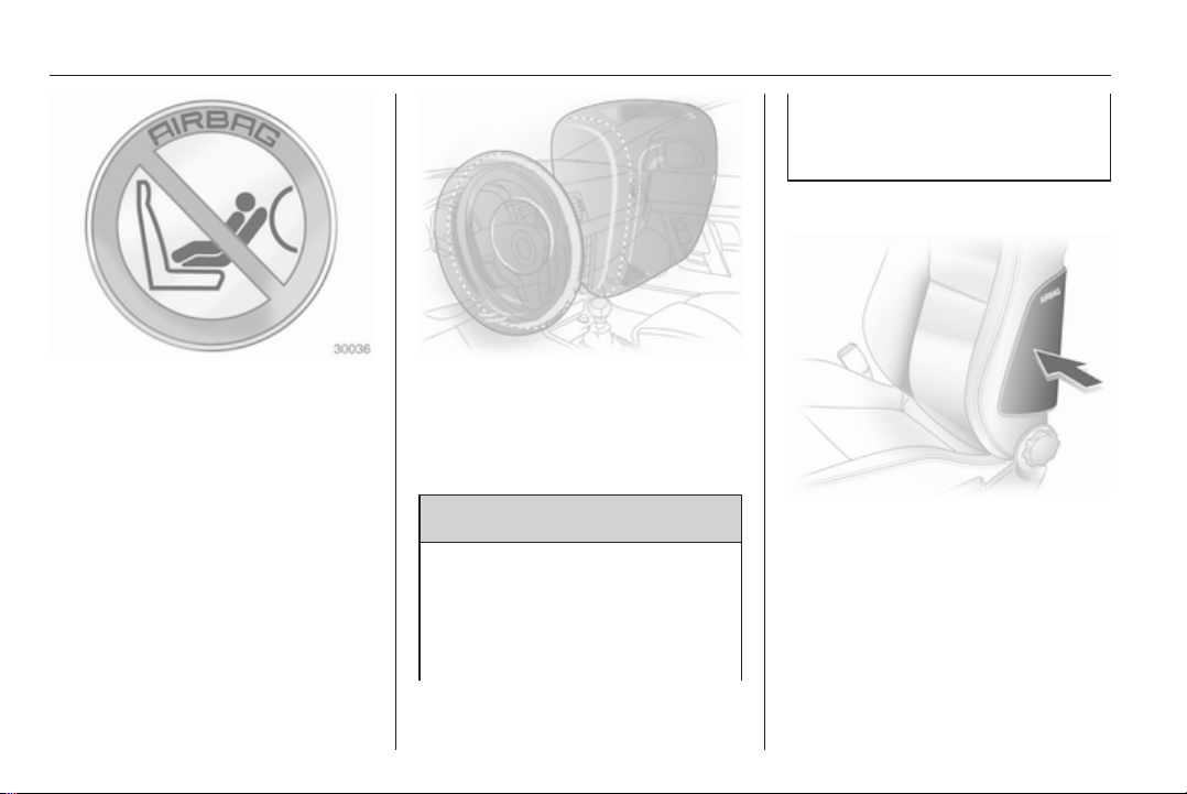
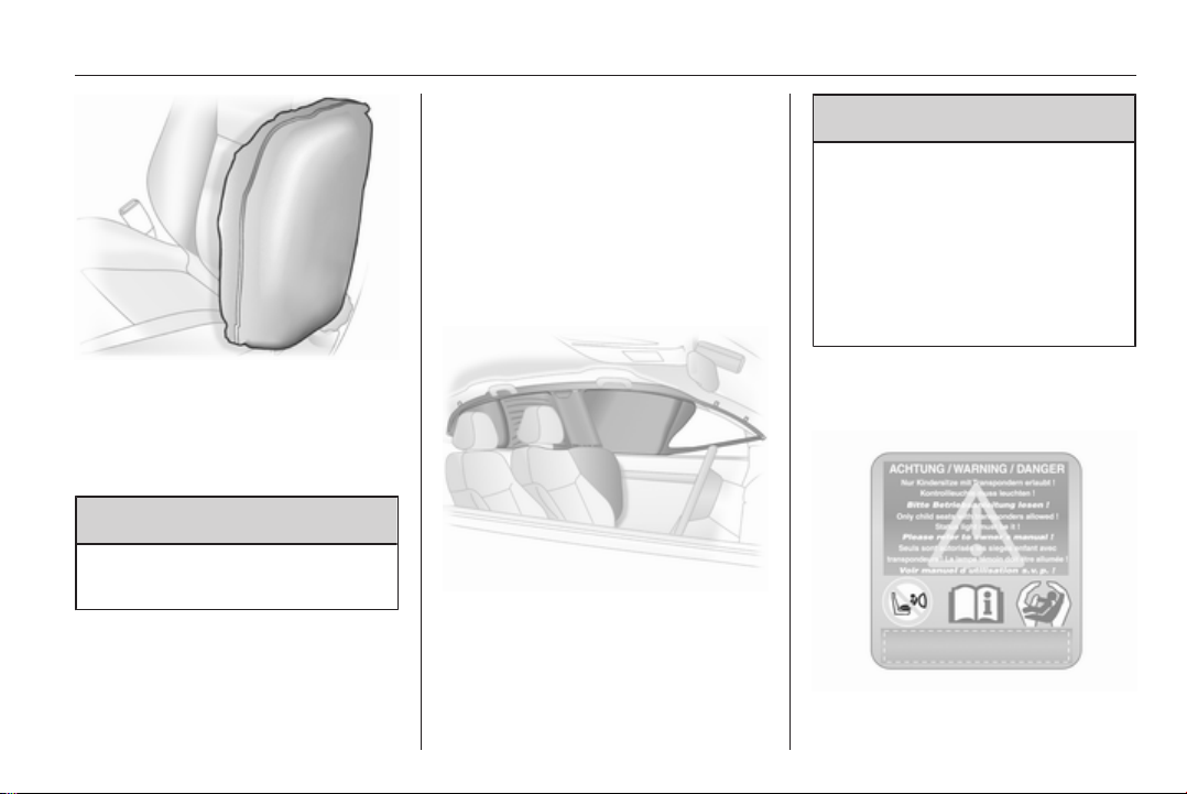
The side airbag system consists of an
airbag in each front seat backrest.
This can be identified by the word
AIRBAG.
The side airbag system is triggered in
the event of a side impact of a certain
severity. The ignition needs to be
switched on.
Seats, restraints 59
The inflated airbags cushion the
impact, thereby reducing the risk of
injury to the upper body and pelvis in
the event of a side-on collision
considerably.
9 Warning
Keep the area in which the airbag
inflates clear of obstructions.
Note
Only use protective seat covers that
have been approved for the vehicle.
Be careful not to cover the airbags.
Curtain airbag system
The curtain airbag system consists of
an airbag in the roof frame on each
side. This can be identified by the
word AIRBAG on the roof pillars.
The curtain airbag system is triggered
in the event of a side-on impact of
a certain severity. The ignition needs
to be switched on.
The inflated airbags cushion the
impact, thereby reducing the risk of
injury to the head in the event of
a side-on impact considerably.
9 Warning
Keep the area in which the airbag
inflates clear of obstructions.
The hooks on the handles in the
roof frame are only suitable for
hanging up light articles of
clothing, without coat hangers. Do
not keep any items in these
clothes.
Seat occupancy recognition

60 Seats, restraints
Identified by a label on the lower
panel of the front passenger seat and
by control indicator y, which
illuminates for approx. 4 seconds
when the ignition is switched on.
The seat occupancy recognition
system deactivates the passenger
front and side airbag if the front
passenger seat is not occupied or is
fitted with an Opel child restraint
system with transponders. The
curtain airbag system remains
activated.
9 Danger
Only Opel child restraint systems
with transponders should be fitted
on the front passenger seats. Use
of systems without transponders
poses a risk of fatal injury.
Control indicator 3 96.
Note
Anyone weighing less than 35 kg
should only travel on the rear seats.
Do not place any heavy objects on
the front passenger seat. Otherwise
the seat will register as occupied and
the airbag system for the front
passenger seat will not be
deactivated.
Do not use protective covers or seat
cushions on the front passenger
seat.
Note
On the Astra TwinTop, there may be
interference in radio reception of
certain frequencies in the medium
waveband when the roof is open and
the front passenger seat is
unoccupied.
Child restraints
Child restraint systems
We recommend the Opel child
restraint system which is tailored
specifically to the vehicle.
When a child restraint system is being
used, pay attention to the following
usage and installation instructions
and also those supplied with the child
restraint system.
Always comply with local or national
regulations. In some countries, the
use of child restraint systems is
forbidden on certain seats.
Selecting the right system
The rear seats are the most
convenient location to fasten a child
restraint system.
Children should travel facing
rearwards in the vehicle as long as
possible. This makes sure that the
child's backbone, which is still very
weak, is under less strain in the event
of an accident.

Seats, restraints 61
Children under the age of 12 years
that are smaller than 150 cm are only
allowed to travel in a restraint system
that is suitable for the child. Suitable
are restraint systems that comply with
ECE 44-03 or ECE 44-04. Since
a proper position of the belt is rarely
possible with a child that is smaller
than 150 cm, we strongly advise to
use an appropriate child restraint
system, even though this might, due
to the age of the child, no longer be
legally binding.
Ensure that the child restraint system
to be installed is compatible with the
vehicle type.
Ensure that the mounting location of
the child restraint system within the
vehicle is correct.
Allow children to enter and exit the
vehicle only on the side facing away
from the traffic.
When the child restraint system is not
in use, secure the seat with a seat belt
or remove it from the vehicle.
Note
Do not stick anything on the child
restraint systems and do not cover
them with any other materials.
A child restraint system which has
been subjected to stress in an
accident must be replaced.

62 Seats, restraints
Child restraint installation locations
Permissible options for fitting a child restraint system
1)
Weight and age class On front passenger seat
Group 0: up to 10 kg or approx. 10 months
Group 0+: up to 13 kg or approx. 2 years
Group I: 9 to 18 kg or approx. 8 months to 4 years
Group II: 15 to 25 kg or approx. 3 to 7 years
Group III: 22 to 36 kg or approx. 6 to 12 years
1
= Limited, only with seat occupancy recognition and Opel child restraint system with transponders.
B
B1, ++
B2, ++
X U U
If the child restraint system is being secured using a three-point seat belt, move seat height adjustment to uppermost
position. Move front passenger seat as far back as possible and move front passenger seat belt anchorage point to
lowest position.
2
= Limited, only with seat occupancy recognition and Opel child restraint system with transponders.
B
If the child restraint system is being secured using a three-point seat belt, move seat height adjustment to uppermost
position. Move front passenger seat as far back as possible so that vehicle safety belt runs from anchorage point
towards the front.
U = Universal suitability in conjunction with three-point seat belt.
+ = Seat available with ISOFIX and Top-tether mounting brackets.
++ = Seat available with ISOFIX mounting brackets.
X = No child restraint system permitted in this weight class.
On outer rear seats
U, + U
U, + U
On centre rear seat
2)
1)
Not allowed on Saloon 4-door.
2)
Not allowed on Astra TwinTop.

Seats, restraints 63
Permissible options for fitting an ISOFIX child restraint system
Weight class Size class Fixture On front passenger seat On rear outboard seats On rear centre seat
Group 0: up to 10 kg E ISO/R1 IL IL X
Group 0+: up to 13 kg E ISO/R1 IL IL X
D ISO/R2 IL IL X
C ISO/R3 X
Group I: 9 to 18 kg D ISO/R2 IL IL X
C ISO/R3 X
B ISO/F2 IL IL, IUF X
B1 ISO/F2X IL IL, IUF X
A ISO/F3 X IL, IUF X
IL = Suitable for particular ISOFIX restraint systems of the 'specific-vehicle', 'restricted' or 'semi-universal' categories.
The ISOFIX restraint system must be approved for the specific vehicle type.
IUF = Suitable for ISOFIX forward-facing child restraint systems of universal category approved for use in this weight class.
X = No ISOFIX child restraint system approved in this weight class.
3)
IL
3)
IL
X
X
3)
Only on the passenger's side.

64 Seats, restraints
ISOFIX size class and seat device
A – ISO/F3 = Forward-facing child restraint system for children of maximum size in the weight class 9 to 18 kg.
B – ISO/F2 = Forward-facing child restraint system for smaller children in the weight class 9 to 18 kg.
B1 – ISO/F2X = Forward-facing child restraint system for smaller children in the weight class 9 to 18 kg.
C – ISO/R3 = Rear-facing child restraint system for children of maximum size in the weight class up to 13 kg.
D – ISO/R2 = Rear-facing child restraint system for smaller children in the weight class up to 13 kg.
E – ISO/R1 = Rear-facing child restraint system for young children in the weight class up to 13 kg.
Seats, restraints 65
Isofix child restraint systems
Fasten vehicle-approved ISOFIX
child restraint systems to the ISOFIX
mounting brackets. Specific vehicle
ISOFIX child restraint system
positions are marked in the table by
IL.
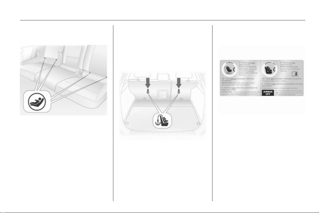
ISOFIX mounting brackets are
indicated by a label on the backrest.
Top-tether child restraint systems
Top-tether fastening eyes are located
under a cover marked with the
symbol : for a child seat. Fold up
cover after usage.
In addition to the ISOFIX mounting,
fasten the Top-tether strap to the
Top-tether fastening eyes. The strap
must run between the two guide rods
of the head restraint.
ISOFIX child restraint systems of
universal category positions are
marked in the table by IUF.
Child restraints with transponders
A label on the child restraint system
indicates that it is fitted with
transponders.
Opel child restraint systems with
transponders are automatically
detected if correctly installed to the
front passenger seat with seat
occupancy recognition.

66 Seats, restraints
Note
There must be no objects (e.g.
plastic sheet or heating mats)
between the seat and the child
restraint system.
Seat occupancy recognition 3 59.
Storage 67
Storage
Storage compartments ................ 67
Load compartment ....................... 68
Roof rack system ......................... 83
Loading information ..................... 84
Storage compartments
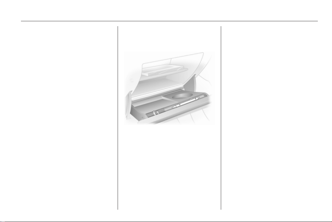
Glovebox
The glovebox features a pen holder
and a place to store coins.
The glovebox shelf can be removed:
Disengage the shelf by pulling on the
front edge.
Refit the shelf by sliding it into the side
guide strips and engage it in the rear
panel by pushing.
The glovebox should be closed whilst
driving.
Lockable glovebox, Astra TwinTop with Open&Start system
In addition to the electronic key of the
Open&Start system, there is
a standard key without remote control
for the glovebox lock.
Cupholders
Cupholders are located in the centre
console and in the door pockets of the
rear doors.
Additional cupholders are located in
the fold-down tables on the back of
the front seat backrests.
68 Storage
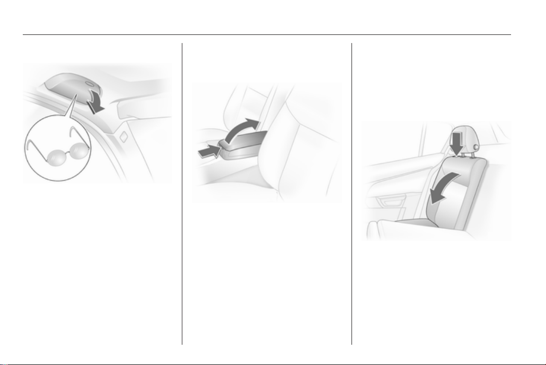
Sunglasses storage
Fold down and open.
Do not use for storing heavy objects.
Armrest storage
Storage in the front armrest
To open, press button and open
upper part of armrest.
Load compartment
Load compartment extension,
Saloon 3-door / 5-door
Folding down rear backrests
Push head restraints all the way down
or remove 3 47.
Slide front seat forward slightly.
Disengage the backrest (single or
split) using the release button on one
or both sides and fold it down onto the
seat cushion.
Storage 69
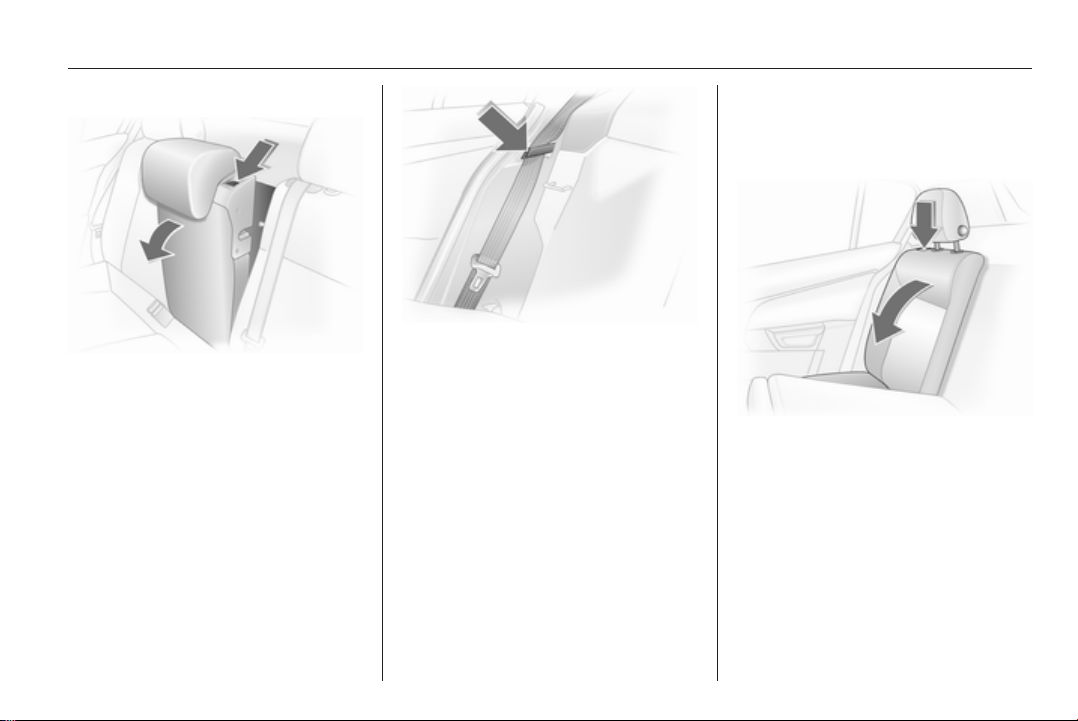
Folding down centre backrests
Push head restraint down as far as
possible 3 47.
Disengage backrest using lever and
fold onto seat cushion.
Before restoring backrest to an
upright position, guide the seat belt
through the belt guides to protect
against damage.
Move rear seat backrests upright and
allow locking mechanisms to engage
audibly.
The three-point seat belt for the
centre rear seat can only be pulled
from the reel if the backrest is properly
engaged.
Load compartment extension,
Saloon 4-door
Folding down rear backrests
Push head restraints all the way down
or remove 3 47.
Slide front seat forward slightly.
70 Storage
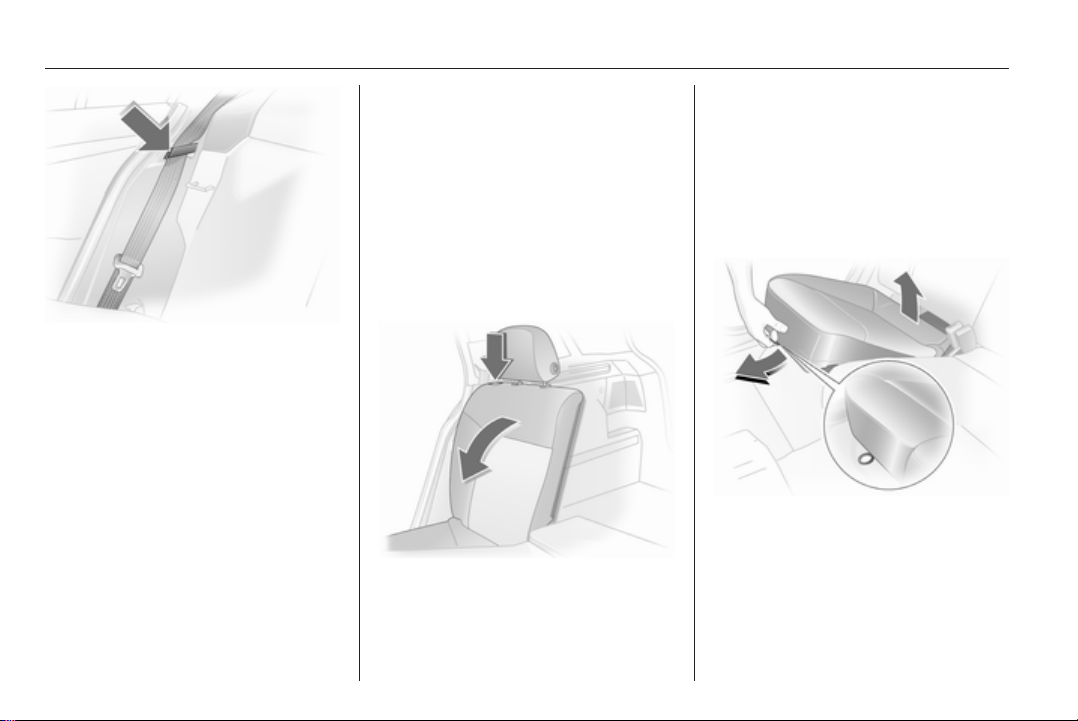
To prevent damage, put the seat belts
in the guides by the release button.
When the backrests are folded, the
seat belts are extended with them.
Disengage the backrest (single or
split) using the release button on one
or both sides and fold it down onto the
seat cushion.
If the vehicle is to be loaded from
a rear door, remove safety belt from
the guide and retract.
To fold up, raise backrests and guide
them into upright position until they
engage audibly.
Do not trap safety belts when erecting
seat backrests.
The three-point seat belt for the
centre rear seat can only be pulled
from the reel if the backrest is properly
engaged.
Load compartment extension,
Station wagon
Folding down rear backrests
Push head restraints all the way down
or remove 3 47.
Unhook hooks of load compartment
cover from head restraints 3 73.
Slide front seat forward slightly.
Disengage the backrest (single or
split) using the release button on one
or both sides and fold it down onto the
seat cushion.
Raise the seat cushion and fold the
backrest
Pull the strap on the seat cushion and
lift the rear of the cushion forwards
(split or one-piece).
Unhook hooks of load compartment
cover from head restraints 3 73.
Storage 71
Folding down centre backrests
Remove rear outer head restraints
and push centre head restraint all the
way down 3 47. Stow the removed
head restraints in the cavity below the
raised seat cushions.
Disengage backrest (one-piece or
split) using release button, fold
forward and engage.
Push head restraint down as far as
possible 3 47. Disengage backrest
using lever and fold onto seat
cushion. If the seat cushion is raised,
fold it forward until it engages.
72 Storage
Load compartment extension,
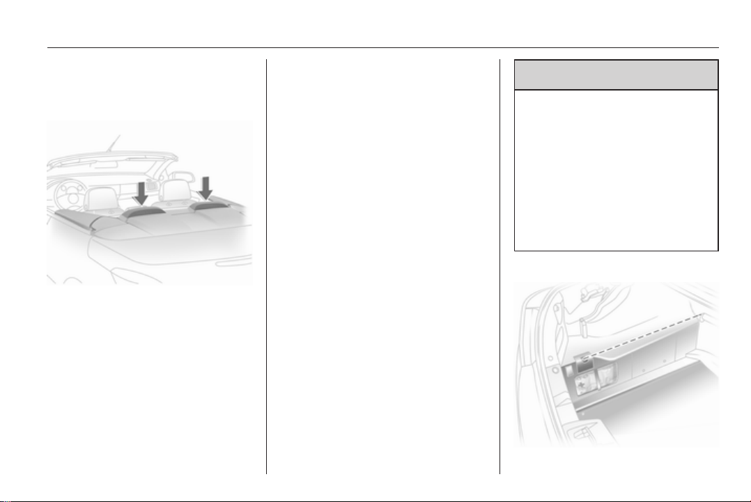
TwinTop
Loading area between rear seats
Before restoring backrest to an
upright position, guide the seat belt
through the belt guides to protect
against damage. Press release
button and move rear seat backrests
upright, ensuring locking
mechanisms engage audibly.
With the seat cushions raised: insert
head restraints in backrests and
adjust 3 47. Fold back seat cushions,
making sure the belt buckles are
properly positioned.
Attach hooks of load compartment
cover to head restraints 3 73.
The three-point seat belt for the
centre rear seat can only be pulled
from the reel if the backrest is properly
engaged.
Pull out the armrest by the strap.
The armrest is held in place on the
backrest with a retaining strap. To
fully remove the armrest, disengage
the bracket at the retaining strap.
Pull the handle and fold down the
cover.
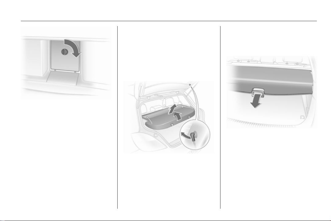
Storage 73
The cover behind the armrest can be
locked from load compartment:
horizontal position = locked
vertical position = unlocked
Stowage in the load
compartment, Station wagon
There is a stowage compartment at
the right side of the load
compartment.
The fuse box is on the left side behind
the cover in the load compartment
side panelling 3 187
Cargo box 3 75.
The tyre repair kit is on the right side
behind the cover 3 196.
Load compartment cover
Saloon 3-door / 5-door
Removing
Unhook retaining straps from tailgate.
Pull cover from the side guides.
Fitting
Engage cover in side guides and fold
downwards. Attach retaining straps to
tailgate.
Station wagon
Do not place any heavy or sharpedged objects on the load
compartment cover.
Opening
Press handle on load compartment
cover rearwards; the cover
automatically engages in its end
position.
Closing
Remove load compartment cover
from side brackets. It rolls up
automatically.
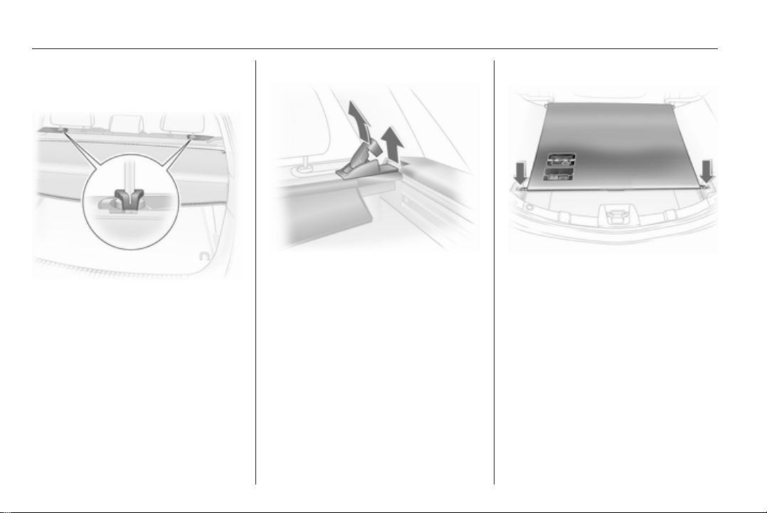
74 Storage
Pull the cover towards the rear using
the handle and engage it in the
retainers at the sides.
To cover the gap between the load
compartment cover and the rear
backrests, there is a cover on the
cartridge. Attach the two hooks of the
cover to the head restraint guide rods.
If the safety net is mounted, run the
hooks through the net mesh.
Removing
Open the load compartment cover
and detach the hooks from the head
restraints.
Pull the release lever. Lift right side of
cover first, then pull left side out of
recess.
Fitting
Insert the left side of the load
compartment cover in the recess, pull
the release lever, insert the right side
of the load compartment cover and
engage.
Attach the hooks on the head
restraints.
TwinTop
Opening
Release load compartment blind from
recesses on left and right, blind rolls
up automatically.
Closing
Pull the cover towards the rear using
the handle and engage it in the
retainers at the sides.
Do not place any objects on the load
compartment cover.
There must be no objects outside of
or on top of the cover when the roof is
open or in the process of opening.
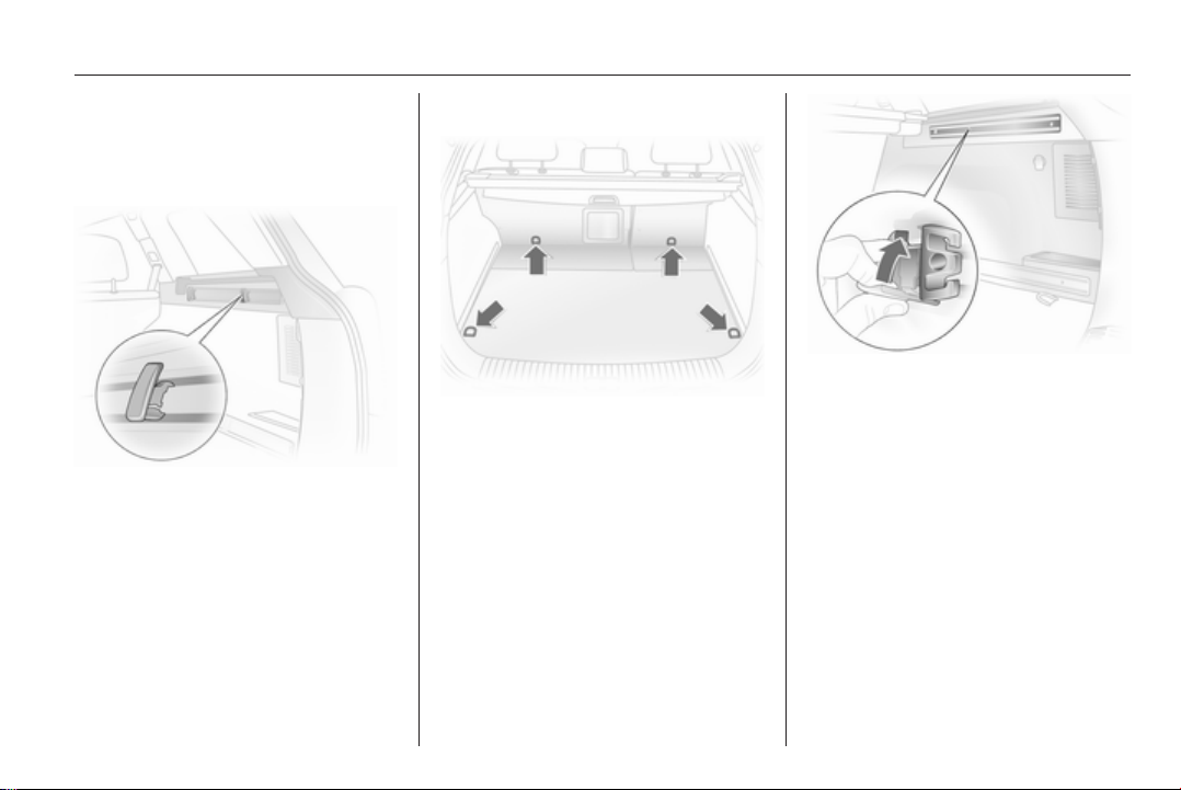
Storage 75
The roof can only be operated with
the blind engaged in the recess.
Load rails and hooks
On Station wagon, install the hooks in
the desired position in the rails: insert
the hook in the upper groove on the
rail and press in the lower groove.
Lashing eyes
The lashing eyes are designed to
secure items against slippage, e.g.
using lashing straps, luggage net or
safety net.
Cargo management system
The FlexOrganizer is a flexible
system for dividing the load
compartment or securing loads in
a Station wagon.
The system consists of
■ adapters
■ variable partition net
■ mesh pockets
■ hooks
The components are fitted in two rails
in the side panels using adapters and
hooks. The partitioning net can also
be fitted directly in front of the tailgate.
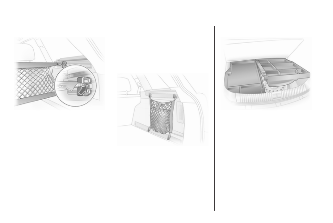
76 Storage
Variable partition net
Insert an adapter into each rail: fold
open the handle plate, insert adapter
into upper and lower groove of rail
and move to required position. Turn
handle plate upwards to lock the
adapter. The rods of the net must be
extended before inserting into the
adapters: pull out all of the end pieces
and lock by rotating clockwise.
To install, push rods together a little
and insert into the relevant openings
in the adapters. The longer rod must
be inserted into the upper adapter.
To remove, press the net rod together
and remove from the adapters. Fold
open the adapter handle plate,
disengage from lower groove and
then from upper groove.
Hooks and net pocket
Net pocket can be suspended from
the luggage hooks.
Cargo box
Foldable box under the floor cover
used to divide the load compartment.
The cargo box may only be loaded
when the backrests are engaged in
an upright position.
To remove the cargo box floor cover,
remove first the right half then the left
half. For models with towing
equipment, first release the coupling
ball bar fixing strap and thread this
through the eye.
Install in reverse order.
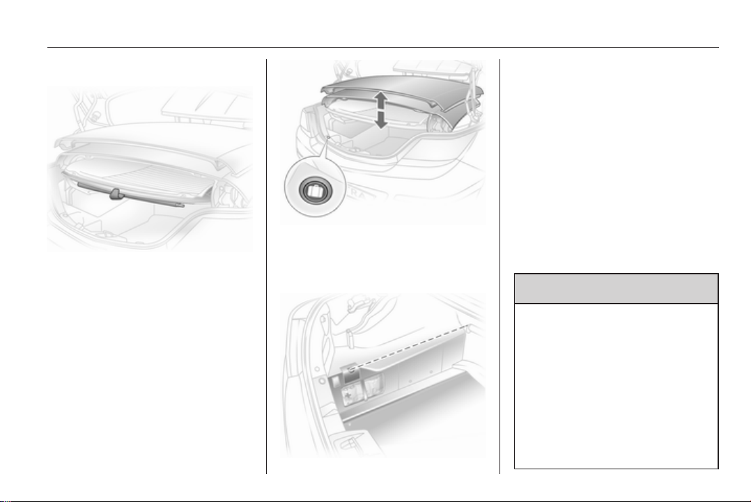
Storage 77
Loading assist
On TwinTop: The loading aid Easy
Load makes it possible to comfortably
load the load compartment when the
roof is open. Pressing the loading aid
button will raise the roof folded up in
the load compartment 25 cm. This
enlarges the load opening of the load
compartment.
■ Open the boot lid
■ Unhook load compartment blind
and attach to rear window frame
with holder
■ Briefly press loading aid button:
The folded roof is raised. The roof
remains in this end position for
approx. 9 minutes
■ Observe marked maximum load
height
■ Suspend the load compartment
blind from the rear window frame
and engage in the recesses. The
load compartment blind must be
flat; objects underneath it must not
push it upwards.
■ Briefly press loading aid button:
The folded roof is lowered.
■ Close the boot lid only after the
confirmation signal has sounded.
Otherwise the roof could be
damaged.
9 Warning
Take care when operating the
loading aid. Risk of injury.
Make sure that nothing can
become trapped.
Make sure no one is in the action
zone during operation. Risk of
injury.
This is especially important for
children. Inform passengers
accordingly.
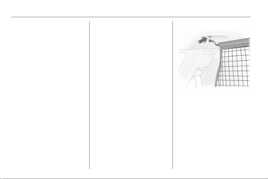
78 Storage
Note
■ Do not place objects on or near the
load compartment blind
■ The folded roof can only be lowered
when the blind is closed.
Otherwise, a warning buzzer will
sound three times
■ The movement of the tilted roof can
be stopped by pressing the loading
aid button and another longer press
reverses the direction of the
movement
■ A confirmation buzzer is heard in
the upper and lower roof end
positions when the roof is tilted
■ Only close the tailgate once the
confirmation signal has sounded to
indicate that the loading aid is in its
lower end position
■ If the loading aid is not in its lower
end position when the boot lid is
closed, a warning tone sounds or
the tailgate is blocked mechanically
3 40
■ Do not touch moving parts
■ One minute before the end of the
hold time for the raised loading aid,
a warning buzzer will sound to
remind you to lower the roof
■ The loading aid is only operable
when the vehicle is unlocked
■ Frequent operation of the loading
aid with the engine off discharges
the battery
■ Repeated operation of the loading
aid can cause malfunctions
Safety net
The safety net is available on the
Station wagon and can be installed
behind the rear seats or, if the rear
seat backrests are folded and the
seat cushions raised, behind the front
seats.
Passengers must not be transported
behind the safety net.
Installation
There are two installation openings in
the roof frame: suspend and engage
rod of net at one side, compress rod
and suspend and engage at other
side.
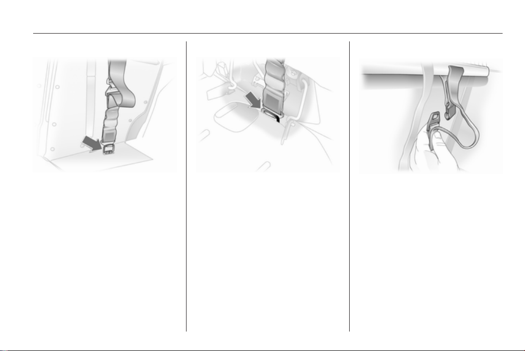
Storage 79
Behind the rear seats
Adjust strap length on safety net by
attaching the upper hook to the eye of
the strap and attach to eyes in the
right and left of the floor.
Behind front seats
Adjust strap length on safety net by
attaching the upper hook to the eye of
the strap and attach to eyes in the
right and left of the floor.
Remove rear outer head restraints
and fold backrests forward.
Removal
Tilt length adjuster of the net
tensioning belt upwards and detach
the belt. Unhook the safety net rods
from the brackets in the roof frame.
Roll up the net and secure with
a strap.
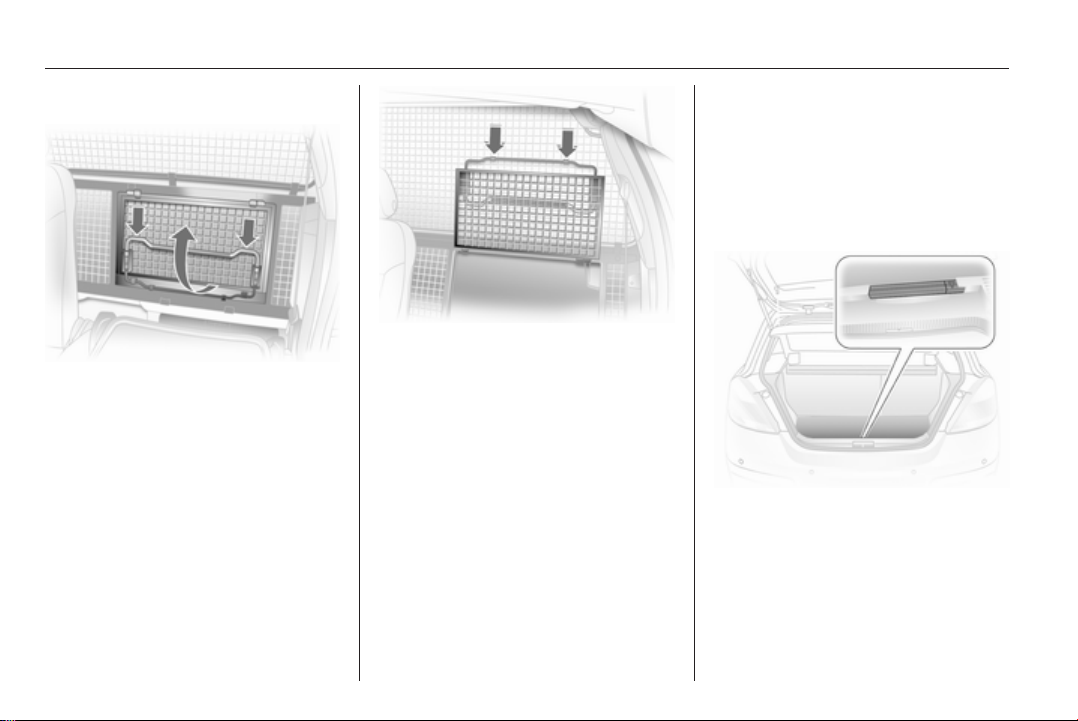
80 Storage
Load compartment grille
To transport long objects, part of the
load compartment grille behind the
passenger seat can be opened:
Release passenger seat back and
fold forward.
Press bracket down and fold grille
section up.
Lock grille in open position.
To close the grille section from the
open position, push bracket down,
fold down grille and engage.
Check that the closed grille is properly
locked.
Folding tray
Located in the front seat backrests.
Open by pulling upward until it
engages.
Fold away by pressing down past the
resistance point.
Do not place any heavy objects on the
folding tray.
Warning triangle
Saloon 3-door / 5-door, TwinTop
Store warning triangle in rear load
compartment wall: first fit warning
triangle into recess on left and then
insert in guide on right.
To remove the warning triangle, lift to
the right and pull out to the right.
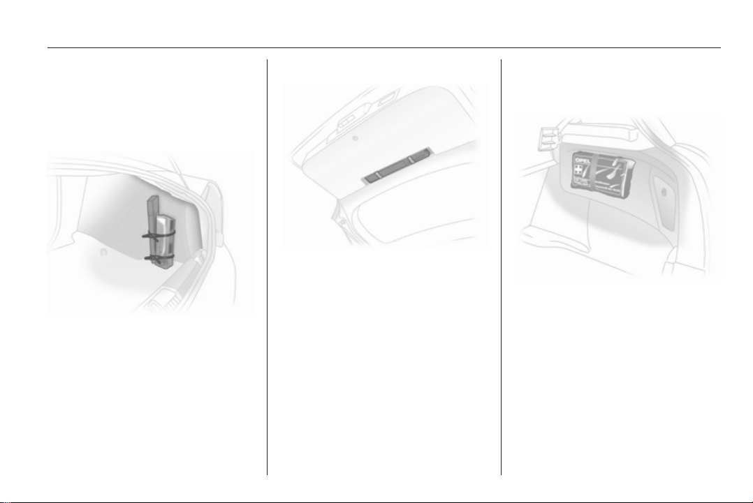
Storage 81
For vehicles with cargo box: Lift the
warning triangle with the right half of
the cargo box. Pull out the warning
triangle to the right.
Saloon 4-door
Attach the warning triangle and first
aid kit in the load compartment
against the panel on the right using
two straps.
Station wagon, Van
Stow the warning triangle in the space
in the tailgate and fasten with the right
and left straps.
First aid kit
Saloon 3-door / 5-door
Secure the first-aid kit to the right load
compartment wall using the retaining
strap.
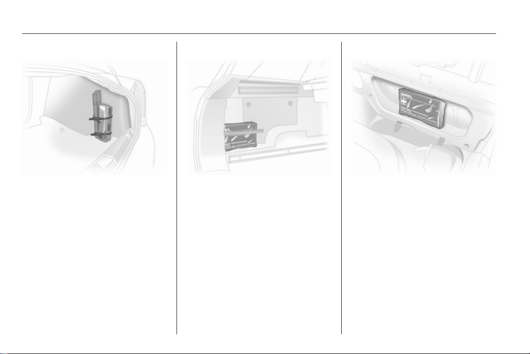
82 Storage
Saloon 4-door
Attach the warning triangle and first
aid kit in the load compartment
against the panel on the right using
two straps.
Station wagon
Fasten the first-aid kit to the left load
compartment wall with a retaining
strap.
Van
Place first aid kit in stowage
compartment behind the driver's seat.
To open the cover, press the locking
tab.
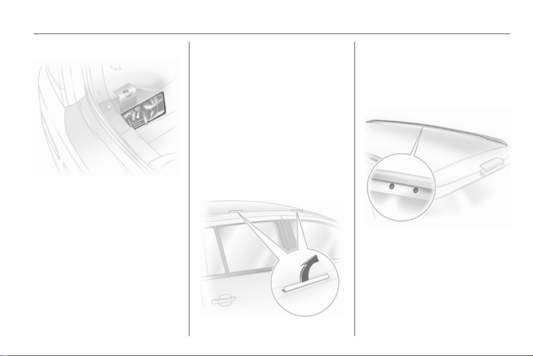
Storage 83
TwinTop
Store the first-aid kit in the recess
behind the strap in the left load
compartment wall.
Roof rack system
Roof rack
For safety reasons and to avoid
damage to the roof, the vehicle
approved roof rack system is
recommended.
Roof loads are not permitted on the
Astra TwinTop.
Follow the installation instructions
and remove the roof rack when not in
use.
Version without roof railing
Lift the covers from the fitting
openings.
Fasten the roof rack at the fastening
points.
Version with roof railing
To fasten the roof rack, insert the
mounting bolts in the holes indicated
in the figure.
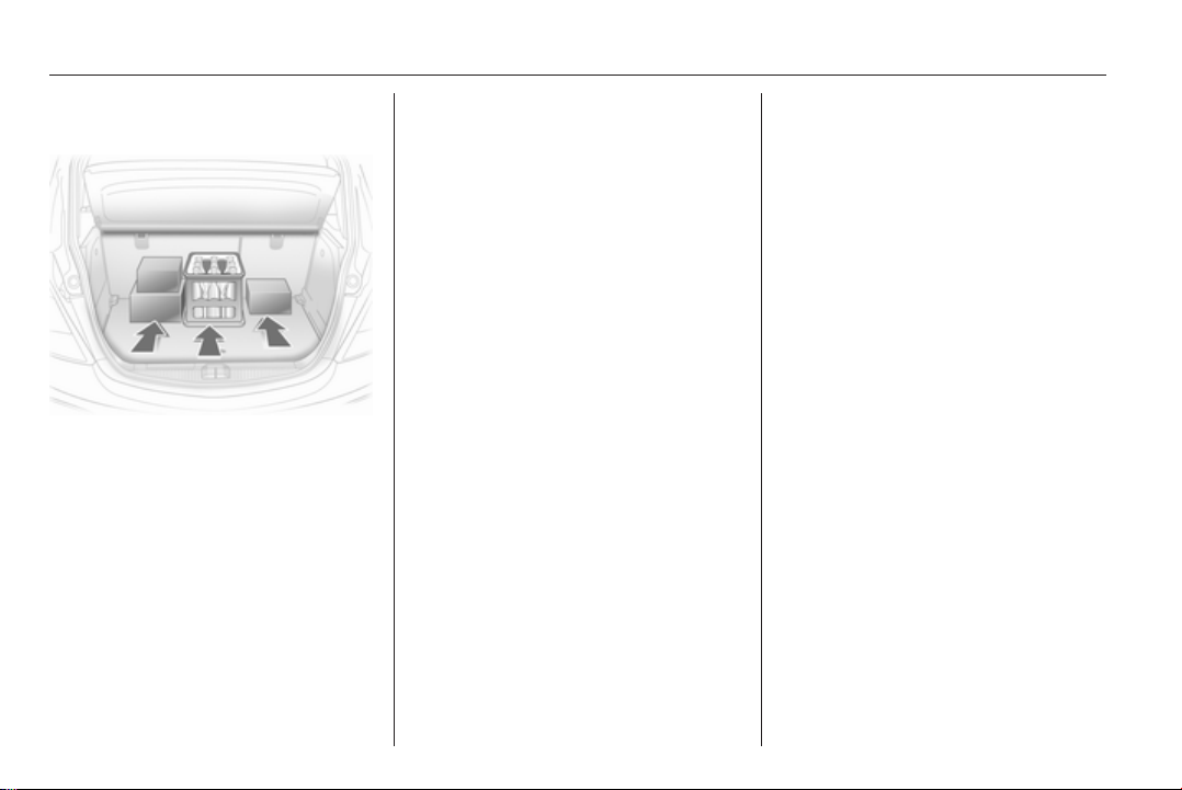
84 Storage
Loading information
■ Heavy objects in the load
compartment should be placed
against the seat backrests. Ensure
the backrests are securely
engaged. If objects can be stacked,
the heavier objects should be
placed at the bottom.
■ Secure objects with lashing straps
attached to lashing eyes 3 75.
■ Secure loose objects in load
compartment to prevent sliding.
■ When transporting objects in the
load compartment, the backrests of
the rear seats must not be angled
forward.
■ Do not allow the load to protrude
above the upper edge of the
backrests.
■ Do not place any objects on the
load compartment cover or the
instrument panel.
■ The load must not obstruct the
operation of the pedals, parking
brake and gear selector, or hinder
the freedom of movement of the
driver. Do not place any unsecured
objects in the interior.
■ Do not drive with an open load
compartment.
■ Station wagon: fit safety net when
objects are being transported in the
load compartment. Close load
compartment cover.
■ Astra TwinTop: pay attention to
maximum loading height with roof
open. Do not place objects on top
of or next to the load compartment
blind, on the cover of the
deployable anti-roll bars or behind
the rear head restraints.
■ The payload is the difference
between the permitted gross
vehicle weight (see identification
plate 3 214) and the EC kerb
weight.
To calculate the EC kerb weight,
enter the data for your vehicle in the
Weights table at the front of this
manual.
The EC kerb weight includes
weights for the driver (68 kg),
luggage (7 kg) and all fluids (tank
90 % full).
Optional equipment and
accessories increase the kerb
weight.
■ Driving with a roof load increases
the sensitivity of the vehicle to
cross-winds and has a detrimental
effect on vehicle handling due to
the vehicle’s higher centre of
gravity. Distribute the load evenly
and secure it properly with retaining
straps. Adjust the tyre pressure and
vehicle speed according to the load

conditions. Check and retighten the
straps frequently.
The permissible roof load is 75 kg
and 100 kg for Station wagon with
roof railing. The roof load is the
combined weight of the roof rack
and the load.
Storage 85
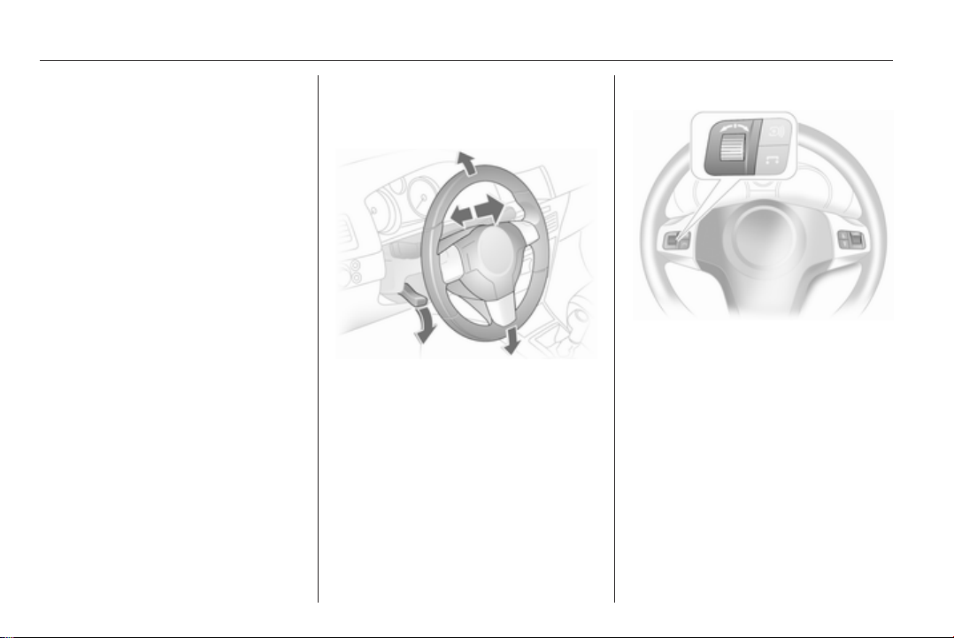
86 Instruments and controls
Instruments and controls
Controls ....................................... 86
Warning lights, gauges and
indicators ..................................... 93
Information displays ................... 102
Vehicle messages ...................... 109
Trip computer ............................. 112
Controls
Steering wheel adjustment
Unlock lever, adjust steering wheel,
then engage lever and ensure it is
fully locked.
Do not adjust steering wheel unless
vehicle is stationary and steering
wheel lock has been released.
Steering wheel controls
The Infotainment system and the
Info-Display can be operated via the
controls on the steering wheel.
Further information is available in the
Infotainment system manual.
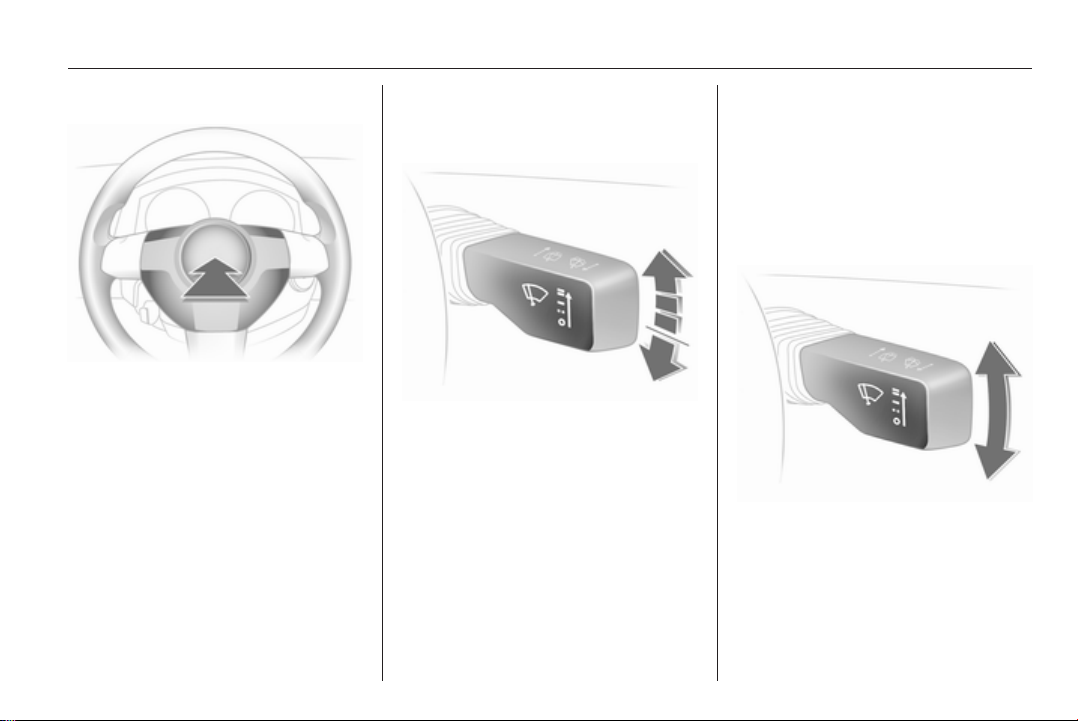
Instruments and controls 87
Horn
Press j.
Windscreen wiper/washer
Windscreen wiper
The lever always springs back to its
original position.
= fast
&
= slow
%
= adjustable timed interval wipe
$
= Off
§
For a single wipe when the
windscreen wiper is off, press the
lever down.
Run through the windscreen wiper
stages by pushing the lever past the
resistance point and holding. An
acoustic signal sounds at §.
Do not use if the windscreen is frozen.
Switch off in car washes.
Adjustable wiper interval
To set the wiper interval to a value
between 2 and 15 seconds: Switch on
ignition, move lever down from
position §, wait desired time interval
and raise lever to $.
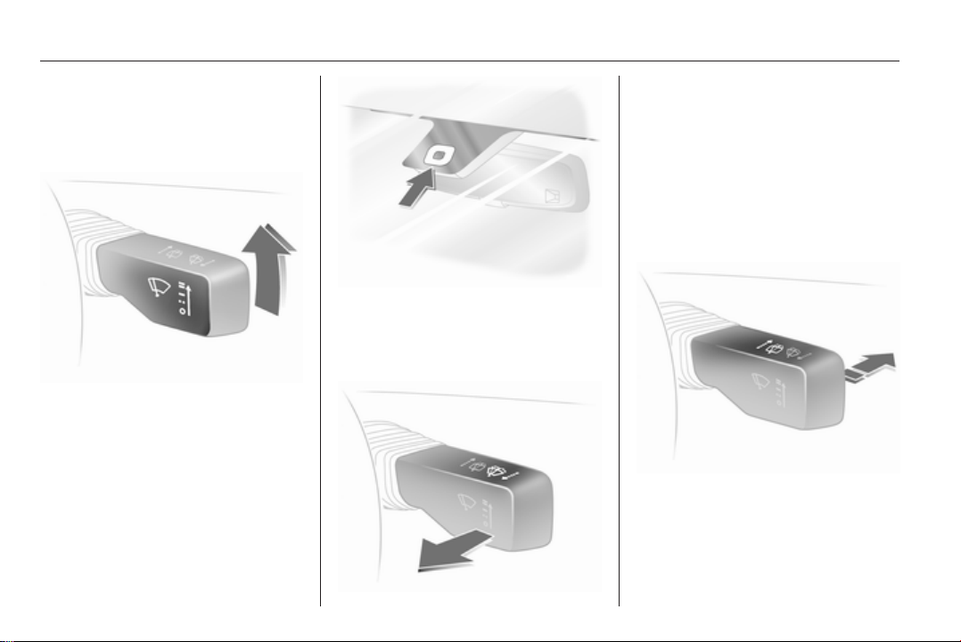
88 Instruments and controls
After turning on the ignition and
setting the lever to $, the interval is
set to 6 seconds.
Automatic wiping with rain sensor
= Automatic wiping with rain
$
sensor
The rain sensor detects the amount of
water on the windscreen and
automatically regulates the frequency
of the windscreen wipers.
Pull lever. Washer fluid is sprayed on
the windscreen and the wiper wipes
for a few strokes.
If the lights are on, washer fluid is also
sprayed on the headlights. The
headlight washer system is then
inoperable for 2 minutes.
Rear window wiper/washer
Keep the sensor free from dust, dirt
and ice.
Windscreen washer
Push lever forwards. The rear window
wiper wipes in interval mode. Switch
off by pushing lever forwards again.
If the lever is held forwards, washer
fluid is sprayed on the rear window.
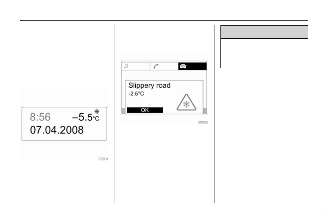
Instruments and controls 89
Do not use if the rear window is
frozen.
Switch off in car washes.
The rear screen wiper comes on
automatically when the windscreen
wiper is switched on and reverse gear
is engaged.
Outside temperature
A drop in temperature is indicated
immediately and a rise in temperature
after a time delay.
If outside temperatures drop to 3 °C,
the symbol : illuminates in the
Triple-Info-Display or the
Board-Info-Display as a warning for
icy road conditions. : remains
illuminated until temperatures reach
at least 5 °C.
In vehicles with Graphic-Info-Display
or Color-Info-Display, a warning
message appears in the display as
a warning for icy road conditions.
There is no message below -5 °C.
9 Warning
The road surface may already be
icy even though the display
indicates a few degrees above
0 °C.
Clock
Date and time are shown in the
Info-Display.
Board-Info-Display 3 102,
Graphic-Info-Display,
Color-Info-Display 3 105.
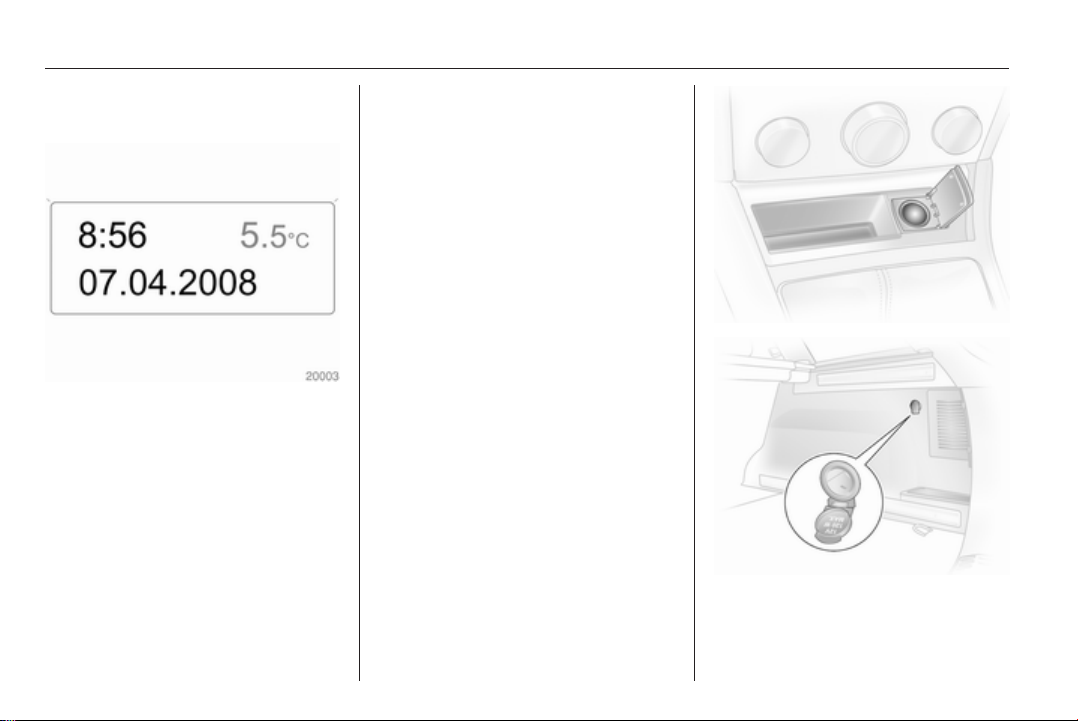
90 Instruments and controls
Set date and time in Triple-Info-Display
To set time, hold the setting button in
the instrument panel depressed for
approx. 2 seconds. A brief press will
set the flashing value. Hold the button
depressed for 2 seconds again to
switch to the next unit and to exit
setting mode.
Automatic time synchronisation
The RDS signal of most VHF
transmitters automatically sets the
time, identified by } in the display.
Some transmitters do not send
a correct time signal. In such cases,
we recommend to switch off
automatic time synchronisation.
Activate setting mode and set it to
year setting. Hold the Ö button
depressed about 3 seconds until }
flashes in the display and “RDS
TIME" appears. The function is
activated (RDS TIME 1) or
deactivated (RDS TIME 0) with
the ; button. Exit setting mode using
the Ö button.
Power outlets
Some vehicles have a power outlet
for the connection of electrical
accessories instead of a cigarette
lighter.
Station wagons have an additional
accessory socket in the load
compartment.
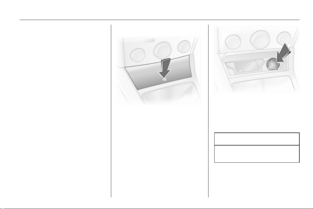
Instruments and controls 91
Connecting electrical accessories
while the engine is off will discharge
the battery.
Do not exceed the maximum power
consumption of 120 Watts.
Electrical accessories connected to
the socket must comply with the
electromagnetic compatibility
requirements laid down in
DIN VDE 40 839.
Do not connect any current-delivering
accessories, e.g. electrical charging
devices or batteries.
Do not damage the power outlets by
using unsuitable plugs.
Cigarette lighter
The cigarette lighter is located behind
the ashtray cover. Press ashtray
cover to open.
Press in cigarette lighter. Switches off
automatically once the element is
glowing. Pull out lighter.
Ashtrays
Caution
To be used only for ash and not for
combustible rubbish.
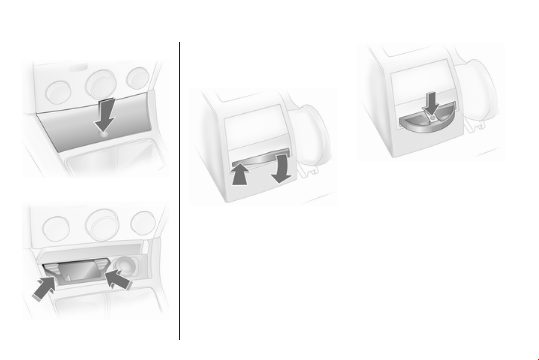
92 Instruments and controls
Ashtray, front
Press ashtray cover to open.
To empty, grip both sides of the
ashtray insert and pull upwards.
Ashtray, rear
To empty, press spring and pull the
ashtray straight out rearwards.
Pull out by pushing on one of the
sides.
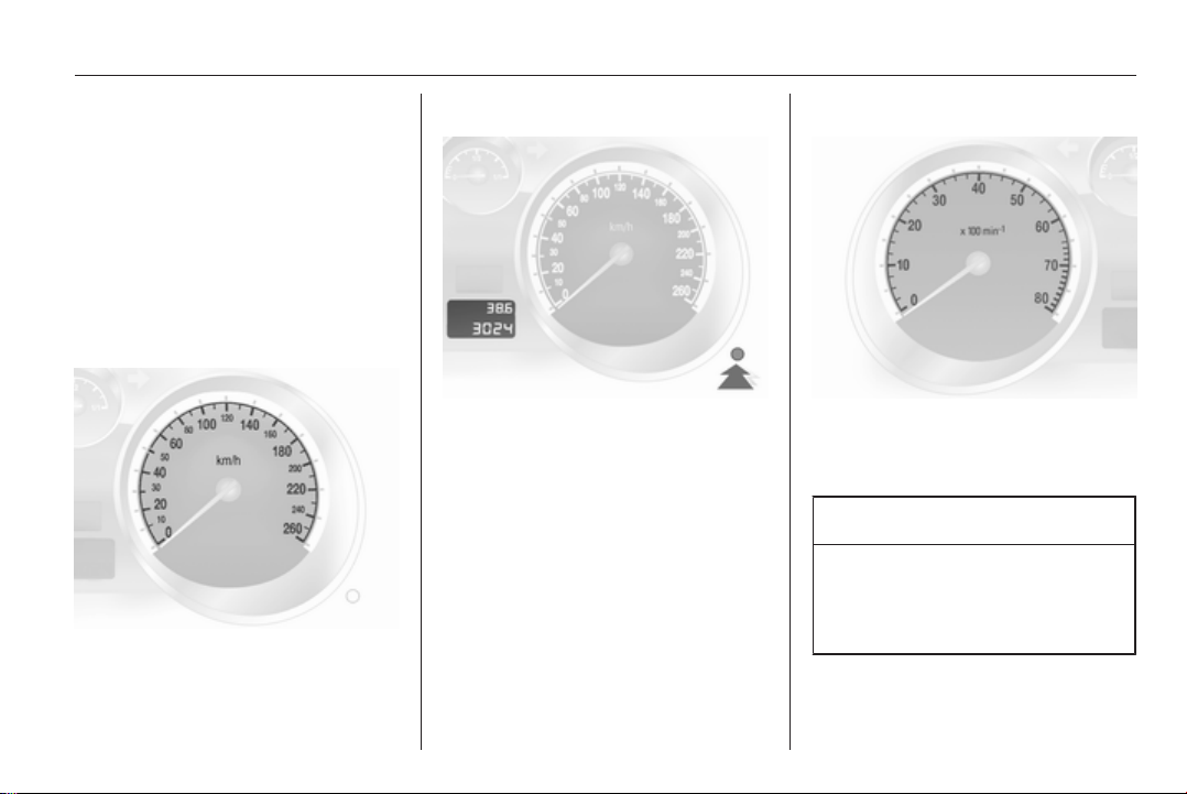
Instruments and controls 93
Warning lights, gauges and indicators
Instrument cluster
In some versions, the needles of the
instruments briefly rotate to the end
position when the ignition is switched
on.
Speedometer
Indicates vehicle speed.
Odometer
The bottom line displays the recorded
distance.
Trip odometer
The top line displays the counted
kilometres since the last reset.
To reset, hold the reset knob
depressed for a few seconds with the
ignition on.
Tachometer
Displays the engine speed.
Drive in a low engine speed range for
each gear as much as possible.
Caution
If the needle is in the red warning
zone, the maximum permitted
engine speed is exceeded. Engine
at risk.
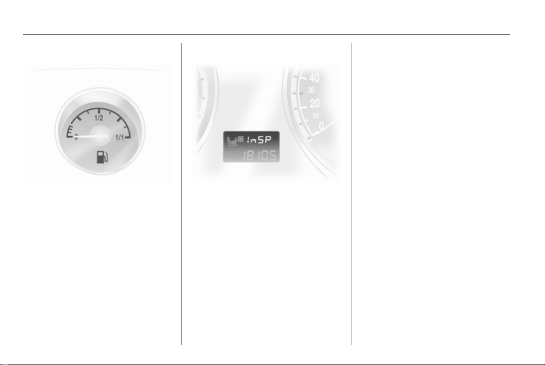
94 Instruments and controls
Fuel gauge
Displays the fuel level in the tank
depending on the operation mode.
Control indicator Y illuminates if the
level in the tank is low. Refuel
immediately if it flashes.
Never run the tank dry.
Because of the fuel remaining in the
tank, the top-up quantity may be less
than the specified tank capacity.
Service display
The message InSP appears when it
is time for servicing. Further
information 3 209.
Control indicators
The control indicators described are
not present in all vehicles. The
description applies to all instrument
versions. When the ignition is
switched on, most control indicators
will illuminate briefly as a functionality
test.
The control indicator colours mean:
Red = Danger, important
reminder,
Yellow = Warning, information,
fault,
Green = Confirmation of activation,
Blue = Confirmation of activation.
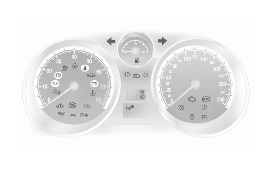
Instruments and controls 95

96 Instruments and controls
Turn signal
O illuminates or flashes green.
Illuminates
The control indicator illuminates
briefly when the parking lights are
switched on.
Flashes
The control indicator flashes if a turn
signal or the hazard warning flashers
are activated.
Rapid flashing: failure of a direction
indicator lamp or associated fuse,
failure of direction indicator lamp on
trailer.
Bulb replacement 3 168. Fuses
3 183.
Turn signals 3 120.
Seat belt reminder
X illuminates or flashes red.
Illuminates
After the ignition is switched on until
the seat belt is fastened.
Flashes
After starting off until the seat belt is
fastened.
Fastening the seat belt 3 55.
Airbag, belt tensioners and anti-roll bars
v illuminates red.
When the ignition is switched on, the
control indicator illuminates for
approx. 4 seconds. If it does not
illuminate, does not go out after
4 seconds or illuminates whilst
driving, there is a fault in the belt
tensioner, the airbags, the deployable
anti-roll bars or the seat occupancy
recognition system. The systems may
fail to trigger in the event of an
accident.
Deployment of the belt tensioners,
airbags or deployable anti-roll bars is
indicated by continuous illumination
of v.
9 Warning
Have the cause of the fault
remedied immediately by
a workshop.
Airbag system, belt tensioners 3 57,
3 54.
Seat occupancy recognition
y illuminates or flashes yellow.
Illuminated
If the vehicle is equipped with seat
occupancy recognition, y illuminates
for approx. 4 seconds after the
ignition is switched on.
If a child restraint system with
transponders is detected, y remains
illuminated. Only then a child restraint
system with transponders may be
used on the front passenger seat as
the front passenger airbag systems
are deactivated 3 59.
Instruments and controls 97
9 Danger
If a child restraint system is fitted
and the control indicator is not
illuminated while driving, the front
and side airbag for the front
passenger seat are not
deactivated.
Flashes
Fault in system or child restraint
system with transponders defective
or improperly fitted 3 59.
9 Danger
Flashing of the control indicator
while driving indicates a fault.
Have the cause of the fault
remedied by a workshop
immediately.
Child restraint system with
transponders 3 65.
Charging system
p illuminates red.
Illuminates when the ignition is
switched on and goes out shortly after
the engine starts.
Illuminates when the engine is running
Stop, switch off engine. Battery is not
charging. Engine cooling may be
interrupted. In diesel engines, power
to the brake servo unit may be cut.
Seek the assistance of a workshop.
Malfunction indicator light
Z illuminates or flashes yellow.
Illuminates when the ignition is
switched on and goes out shortly after
the engine starts.
Illuminates when the engine is running
Fault in the emission control system.
The permitted emission limits may be
exceeded. Immediately seek the
assistance of a workshop.
Flashes when the engine is running
Fault that could lead to catalytic
converter damage. Ease up on the
accelerator until the flashing stops.
Seek the immediate assistance of
a workshop.
Service vehicle soon
A illuminates or flashes yellow.
Illuminates when the engine is running
Fault in engine or transmission
electronics 3 143, 3 147. The
electronics switch to an emergency
running programme. Fuel
consumption may be increased and
the vehicle handling may be impaired.
If the fault persists after restarting the
vehicle, consult a workshop.
Illuminates together with InSP4 in the service display
Seek the assistance of a workshop for
draining the diesel fuel filter 3 110.

98 Instruments and controls
Flashes with switched on ignition
Fault in the immobiliser system. The
engine cannot be started 3 32.
Switch off the ignition and repeat the
start attempt.
If the control indicator continues
flashing, attempt to start the engine
using the spare key and seek the
assistance of a workshop.
Brake and clutch system
R illuminates or flashes red.
Illuminated
Illuminates after the ignition is
switched on if the parking brake is
applied 3 150.
Illuminates when the parking brake is
released if the brake and clutch fluid
level is too low 3 166.
9 Warning
Stop. Do not continue your
journey. Consult a workshop.
Flashes
On vehicle with automated manual
transmission, flashes for a few
seconds when the ignition is switched
off if the parking brake is not applied.
On vehicles with automated manual
transmission, flashes when the
driver's door is opened if no gear is
engaged and the parking brake is not
applied.
Antilock brake system (ABS)
u illuminates red.
Illuminates for a few seconds after the
ignition is turned on. The system is
ready for operation when the control
indicator goes out.
If the control indicator does not go out
after a few seconds, or if it illuminates
while driving, there is a fault in the
ABS. The brake system remains
operational but without ABS
regulation.
Antilock Brake System 3 149.
Sport mode
1 illuminates yellow.
The symbol is illuminated when Sport
mode is on 3 142, 3 146.
Winter mode
T illuminates yellow.
The symbol is illuminated when
Winter mode is on 3 142, 3 146.
Ultrasonic parking assist
r illuminates or flashes yellow.
Illuminates
Fault in system. Have the cause of the
fault remedied by a workshop.
Flashes
Fault due to sensors that are dirty or
covered by ice or snow.
or
Interference due to external sources
of ultrasound. Once the source of
interference is removed, the system
will operate normally.
Instruments and controls 99
Ultrasonic parking sensors 3 153.
Electronic Stability Program
v flashes or illuminates yellow.
Illuminates for a few seconds when
the ignition is switched on.
Flashes whilst driving
The system is actively engaged.
Engine output may be reduced and
the vehicle may be braked
automatically to a small degree
3 150.
Illuminates whilst driving
The system is switched off or a fault
is present. Continued driving is
possible. Driving stability, however,
may deteriorate depending on road
surface conditions.
Have the cause of the fault remedied
by a workshop.
Plus
ESP®
3 150.
Engine coolant temperature
W illuminates red.
Illuminates when the engine is running
Stop, switch off engine.
Caution
Coolant temperature too high.
Check coolant level immediately
3 165.
If there is sufficient coolant, consult
a workshop.
Preheating and diesel particle filter
! illuminates or flashes yellow.
Illuminates
Preheating activated. Only activates
when outside temperature is low.
Flashes
in vehicles fitted with a diesel particle
filter.
Control indicator ! flashes if the filter
requires cleaning and previous
driving conditions did not permit
automatic cleaning. Continue driving
and if possible do not allow engine
speed to drop below 2000 rpm.
The control indicator ! goes off as
soon as the self-cleaning operation is
complete.
Diesel particle filter 3 138.
Deflation detection system and tyre pressure monitoring system
w illuminates or flashes red or yellow.
Control indicator illuminates red
Tyre pressure loss. Stop immediately
and check tyre pressure. A maximum
speed of 80 km/h is permitted for runflat tyres 3 191.
100 Instruments and controls
Control indicator illuminates yellow
Fault in system or tyre without
pressure sensor mounted (e.g. spare
wheel). Consult a workshop.
Flashes
Flashes three times to indicate
system initialisation.
Deflation detection system 3 194,
tyre pressure monitoring system
3 193.
Interactive driving system, continuous damping control, sport mode
IDS+ illuminates yellow.
Illuminates when the ignition is
switched on and goes out shortly after
the engine starts. Illumination whilst
driving indicates a fault in the system.
Have the cause of the fault remedied
by a workshop.
Plus
IDS
3 151, CDC 3 152, Sport
mode 3 151.
Engine oil pressure
I illuminates red.
Illuminates when the ignition is
switched on and goes out shortly after
the engine starts.
Illuminates when the engine is running
Caution
Engine lubrication may be
interrupted. This may result in
damage to the engine and/or
locking of the drive wheels.
1. Depress clutch.
2. Select neutral gear, set selector
lever to N.
3. Move out of the flow of traffic as
quickly as possible without
impeding other vehicles.
4. Switch off ignition.
9 Warning
When the engine is off,
considerably more force is needed
to brake and steer.
Do not remove key until vehicle is
stationary, otherwise the steering
wheel lock could engage
unexpectedly.
Check oil level before seeking the
assistance of a workshop 3 164.
Low engine oil level
S illuminates yellow.
Engine oil level is checked
automatically.
Illuminates when the engine is running
Low engine oil level. Check engine oil
level and top up as necessary
3 164.
Low fuel
Y illuminates or flashes yellow.
 Loading...