


Vauxhall Cavalier
Service and Repair Manual
Steve Rendle and Finn Deacon
Models covered
Vauxhall Cavalier front-wheel-drive models with four-cylinder petrol engines, including special/limited editions; Saloon and Hatchback
1398 cc, 1598 cc, 1796 cc & 1998 cc (inc. DOHC)
Does not cover Diesel engine, V6 engine, air conditioning or four-wheel-drive models |
1570 - 320 - 6AA10 |
© Haynes Publishing 1997
A book in the Haynes Service and Repair Manual Series
All rights reserved. No part of this book may be reproduced or transmitted in any form or by any means, electronic or mechanical, including photocopying, recording or by any information storage or retrieval system, without permission in writing from the copyright holder.
ISBN 1 85960 088 3
British Library Cataloguing in Publication Data
A catalogue record for this book is available from the British Library.
Printed by J H Haynes & Co. Ltd, Sparkford, Nr Yeovil,
Somerset BA22 7JJ
Haynes Publishing
Sparkford, Nr Yeovil, Somerset BA22 7JJ, England
Haynes North America, Inc
861 Lawrence Drive, Newbury Park, California 91320, USA
Editions Haynes S.A.
147/149, rue Saint Honoré, 75001 PARIS, France
Haynes Publishing Nordiska AB
Fyrisborgsgatan 5, 754 50 Uppsala, Sverige

Contents
LIVING WITH YOUR VAUXHALL CAVALIER
Introduction to the Vauxhall Cavalier |
Page |
0•4 |
Safety first! |
Page |
0•5 |
|
|
|
Roadside Repairs
Introduction |
Page |
0•6 |
If your car won’t start |
Page |
0•6 |
|
|
|
Jump starting |
Page |
0•7 |
|
|
|
Wheel changing |
Page |
0•8 |
|
|
|
Identifying leaks |
Page |
0•9 |
|
|
|
Towing |
Page |
0•9 |
|
|
|
Weekly Checks
Introduction |
Page |
0•10 |
Underbonnet check points |
Page |
0•10 |
|
|
|
Engine oil level |
Page |
0•12 |
|
|
|
Coolant level |
Page |
0•12 |
|
|
|
Screen washer fluid level |
Page |
0•13 |
|
|
|
Brake fluid level |
Page |
0•13 |
|
|
|
Power steering fluid level |
Page |
0•14 |
|
|
|
Electrical system |
Page |
0•14 |
|
|
|
Battery |
Page |
0•15 |
|
|
|
Wiper blade |
Page |
0•15 |
|
|
|
Tyre condition and pressure |
Page |
0•16 |
|
|
|
Lubricants, fluids and tyre pressures
Page 0•17
MAINTENANCE
Routine Maintenance and Servicing
Maintenance schedule |
Page |
1•4 |
Maintenance procedures |
Page |
1•8 |
|
|
|

Contents
REPAIRS AND OVERHAUL
Engine and Associated Systems
SOHC engine procedures |
Page |
2A•1 |
DOHC engine procedures |
Page |
2B•1 |
|
|
|
Cooling, heating and ventilation systems |
Page |
3•1 |
|
|
|
Fuel/exhaust systems - carburettor models |
Page |
4A•1 |
|
|
|
Fuel/exhaust systems - fuel injection models |
Page |
4B•1 |
|
|
|
Fuel/exhaust systems - exhaust and emissions |
Page |
4C•1 |
|
|
|
Engine electrical systems |
Page |
5•1 |
|
|
|
Transmission
Clutch |
Page |
6•1 |
Manual transmission |
Page |
7A•1 |
|
|
|
Automatic transmission |
Page |
7B•1 |
|
|
|
Driveshafts |
Page |
8•1 |
|
|
|
Brakes and Suspension
Braking system |
Page |
9•1 |
Suspension and steering |
Page |
10•1 |
|
|
|
Body equipment
Bodywork and fittings |
Page |
11•1 |
Body electrical systems |
Page |
12•1 |
|
|
|
Wiring Diagrams
Page 12•22
REFERENCE
Dimensions and weights |
Page |
REF•1 |
Conversion factors |
Page |
REF•2 |
|
|
|
Buying spare parts and vehicle identification |
Page |
REF•3 |
|
|
|
General repair procedures |
Page |
REF•4 |
|
|
|
Jacking and vehicle support |
Page |
REF•5 |
|
|
|
Radio/cassette unit anti-theft system |
Page |
REF•5 |
|
|
|
Tools and working facilities |
Page |
REF•6 |
|
|
|
MOT test checks |
Page |
REF•8 |
|
|
|
Fault finding |
Page REF•12 |
|
|
|
|
Glossary of technical terms |
Page REF•20 |
|
|
|
|
Index
Page REF•25
0•4 |
Introduction |
|
|||||
The Cavalier covered by this manual was first introduced to the UK Your Vauxhall Cavalier Manual |
|||||||
market in October 1988. Although there is a fundamental similarity to |
The aim of this manual is to help you get the best value from your |
||||||
its predecessor, the later version is much improved in all respects. This |
|||||||
vehicle. It can do so in several ways. It can help you decide what work |
|||||||
manual covers models with petrol engines and front-wheel-drive, but |
|||||||
must be done (even should you choose to get it done by a garage). It |
|||||||
other models in the range are fitted with diesel engines, and four-wheel |
|||||||
will also provide information on routine maintenance and servicing, and |
|||||||
drive is available on certain models. |
|
|
|||||
|
|
give a logical course of action and diagnosis when random faults |
|||||
Thirteen derivatives of 1.4, 1.6, 1.8 and 2.0 litre single overhead |
|||||||
occur. However, it is hoped that you will use the manual by tackling the |
|||||||
camshaft (SOHC) versions and 2.0 litre double overhead camshaft |
|||||||
work yourself. On simpler jobs it may even be quicker than booking the |
|||||||
(DOHC) petrol engines have been fitted. |
|
|
|||||
|
|
car into a garage and going there twice, to leave and collect it. Perhaps |
|||||
The latest ‘ECOTEC’ engines (X 16 SZ and X 20 XEV), have been |
|||||||
most important, a lot of money can be saved by avoiding the costs a |
|||||||
designed to meet strict EEC exhaust gas limits for 1996. |
|||||||
garage must charge to cover its labour and overheads. |
|||||||
All |
the engines are |
of |
well-proven design and, provided regular |
||||
The manual has drawings and descriptions to show the function of |
|||||||
maintenance is carried out, are unlikely to give trouble. |
|||||||
the various components so that their layout can be understood. Tasks |
|||||||
Saloon and Hatchback body styles are available. In it’s later years |
|||||||
are described and photographed in a clear step-by-step sequence. |
|||||||
models started from a well-equipped ‘Envoy’ base model up to the |
|||||||
|
|||||||
sporty SRi. |
|
|
|
|
|
||
Selected models use the floorpan layout of |
|
|
|||||
the |
four-wheel-drive |
models, |
to |
|
|
||
accommodate fully |
independent |
rear |
|
|
|||
suspension. Other models in the range have |
|
|
|||||
semi-independent torsion beam rear |
|
|
|||||
suspension. |
|
|
|
|
|
||
A five-speed manual transmission is fitted as |
|
|
|||||
standard to all models, and four-speed |
|
|
|||||
automatic transmission is available as an option. |
|
|
|||||
A wide range of standard and optional |
|
|
|||||
equipment is available within the Cavalier |
|
|
|||||
range to suit most tastes, including an |
|
|
|||||
anti-lock braking system. |
|
|
|
|
|||
Safety features such as front and rear, side |
|
|
|||||
impact bars fitted to the inside of doors, were |
|
|
|||||
fitted as standard from 1993. During the same |
|
|
|||||
year, a full-size drivers airbag was introduced. |
|
|
|||||
1994 saw the introduction of airbags for front |
|
|
|||||
seat passengers. |
|
|
|
|
|
||
For the home mechanic, the Cavalier is a |
|
|
|||||
straightforward vehicle to maintain, and most |
|
|
|||||
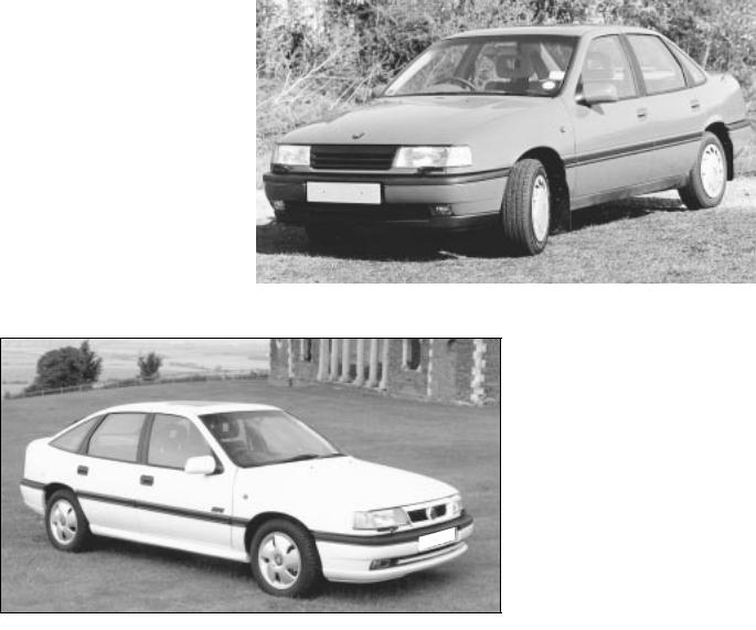
|
Cavalier 2.0 litre SRi Saloon |
||||||
of the items requiring frequent attention are |
|||||||
|
|||||||
easily accessible. |
|
|
|
|
|
||
Cavalier SRi 16v
Hatchback
Acknowledgements
Thanks are due to Champion Spark Plug who supplied the illustrations showing spark plug conditions. Thanks are also due to SykesPickavant Limited, who provided some of the workshop tools, and to all those people at Sparkford who helped in the production of this manual. Certain illustrations are the copyright of Vauxhall Motors Ltd, and are used with their permission.
We take great pride in the accuracy of information given in this manual, but vehicle manufacturers make alterations and design changes during the production run of a particular vehicle of which they do not inform us. No liability can be accepted by the authors or publishers for loss, damage or injury caused by errors in, or omissions from, the information given.

Safety First! 0•5
Working on your car can be dangerous. This page shows just some of the potential risks and hazards, with the aim of creating a safety-conscious attitude.
General hazards
Scalding
•Don’t remove the radiator or expansion tank cap while the engine is hot.
•Engine oil, automatic transmission fluid or power steering fluid may also be dangerously hot if the engine has recently been running.
Burning
• Beware of burns from the exhaust system and from any part of the engine. Brake discs and drums can also be extremely hot immediately after use.
Crushing
•When working a raised vehicle, always supplement the jack with axle stands, or use drive-on ramps.
Never venture under a car
is only supported
•Take care if torque nuts Initial loosening be done with
Fire
•Fuel is highly explosive.
•Don’t let fuel
•Do not smoke (including pilot vehicle being creating sparks (electrically or by
•Fuel vapour is work on the fuel an inspection pit
•Another cause overload or short repairing or
•Keep a fire suitable for use
Electric shock
• Ignition HT voltage can be dangerous, especially to people with heart problems or a pacemaker. Don’t work on or near ignition system the engine running
the ignition switched on.
• Mains voltage is also dangerous. Make sure that any mains-operated equipment is correctly earthed. Mains power points should be protected by a residual current device (RCD) circuit breaker.
Fume or gas intoxication
•Exhaust fumes are poisonous; they contain carbon monoxide, which is rapidly fatal if inhaled Never run the engine in a
confined space such as a garage with the doors shut
•Fuel vapour is also poisonous, as are cleaning solvents
your pocket.
• Air conditioning poisonous gas if (including a cigarette) burns on contact.
Specia hazards
Hydrofluoric acid
• This extremely corrosive acid is formed when certain types of synthetic rubber, found in some O-rings, oil seals, fuel hoses etc, are exposed to temperatures above 4000C. The
changes into a charred or sticky containing the acid. Once formed,
remains dangerous for years. If it the skin, it may be necessary to the limb concerned.
dealing with a vehicle which has
a fire, or with components salvaged a vehicle, wear protective gloves
them after use.
battery
• Batteries contain sulphuric acid, which attacks clothing, eyes and skin. Take care
topping-up or carrying the battery. hydrogen gas given off by the battery
explosive. Never cause a spark or naked light nearby. Be careful when and disconnecting battery
or jump leads.
can cause injury if they go off
. Take care when removing the wheel and/or facia. Special storage
instructions may apply.
Diesel injection equipment
• Diesel injection pumps supply fuel at very high pressure. Take care when working on the fuel injectors and fuel pipes.
Asbestos
• Asbestos dust can |
Warning: Never expose the hands, |
or swallowed. |
face or any other part of the body |
gaskets and in brake |
to injector spray; the fuel can |
When dealing with |
penetrate the skin with potentially fatal |
safest to assume |
results. |
Remember... |
A few tips |
|
DO |
DON’T |
|
• Do use eye protection when using power |
• Don’t attempt to lift a heavy component |
|
tools, and when working under the vehicle. |
which may be beyond your capability – get |
|
• Do wear gloves or use barrier cream to |
assistance. |
|
• Don’t rush to finish a job, or take |
||
protect your hands when necessary. |
||
• Do get someone to check periodically |
unverified short cuts. |
|
• Don’t use ill-fitting tools which may slip |
||
that all is well when working alone on the |
||
vehicle. |
and cause injury. |
|
• Do keep loose clothing and long hair well |
• Don’t leave tools or parts lying around |
|
out of the way of moving mechanical parts. |
where someone can trip over them. Mop |
|
• Do remove rings, wristwatch etc, before |
up oil and fuel spills at once. |
|
• Don’t allow children or pets to play in or |
||
working on the vehicle – especially the |
||
electrical system. |
near a vehicle being worked on. |
|
• Do ensure that any lifting or jacking |
|
|
equipment has a safe working load rating |
|
|
adequate for the job. |
|
|
|
|
0•6 Roadside repairs
The following pages are intended to help in dealing with common roadside emergencies and breakdowns. You will find more detailed fault finding information at the back of the manual, and repair information in the main Chapters.
If your car won’t start and the starter motor doesn’t turn
If your car won’t start even though the starter motor turns as normal
MIf it’s a model with automatic transmission, make sure the selector is in ‘P’ or ‘N’.
MOpen the bonnet and make sure that the battery terminals are clean and tight.
MSwitch on the headlights and try to start the engine. If the headlights go very dim when you’re trying to start, the battery is probably flat. Get out of trouble by jump starting (see next page) using a friend’s car.
MIs there fuel in the tank, or is the gauge faulty?
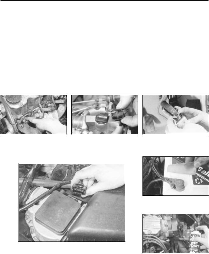
MIs there moisture on electrical components under the bonnet? Switch off the ignition, then wipe off any obvious dampness with a dry cloth. Spray a water-repellent aerosol product (WD-40 or equivalent) on ignition and fuel system electrical connectors like those shown in the photos.
Pay special attention to the ignition coil wiring connector and HT leads. (lights, heater, wipers, etc) is switched off.
A Check that the spark plug HT leads are securely connected by pushing them home.
B may cause problems if not connected securely.
C (where fitted), with the ignition switched off.
D Check the security and condition of the battery connections.
Check that electrical connections are secure (with the ignition switched off) and spray them with a water dispersant spray like WD40 if you
suspect a problem due to damp
E Check that the ignition coil wiring plug is secure, and spray with waterdispersant if necessary.
Roadside repairs 0•7
Jump starting will get you out of trouble, but you must correct


 whatever made the battery go flat in the first place. There are three possibilities:
1The battery has been drained by repeated attempts to start, or by
leaving the lights on.
2The charging system is not working properly (alternator drivebelt slack
or broken, alternator wiring fault or alternator itself faulty).
3The battery itself is at fault (electrolyte low, or battery worn out).
When jump-starting a car using a booster battery, observe the following precautions:
Before connecting the booster battery, make sure that the ignition is switched off.
Ensure that all electrical equipment (lights, heater, wipers, etc) is switched off.
Jump starting
Make sure that the booster battery is the same voltage as the discharged one in the vehicle.
If the battery is being jump-started from the battery in another vehicle, the two vehcles MUST NOT TOUCH each other.
Make sure that the transmission is in neutral (or PARK, in the case of automatic transmission).
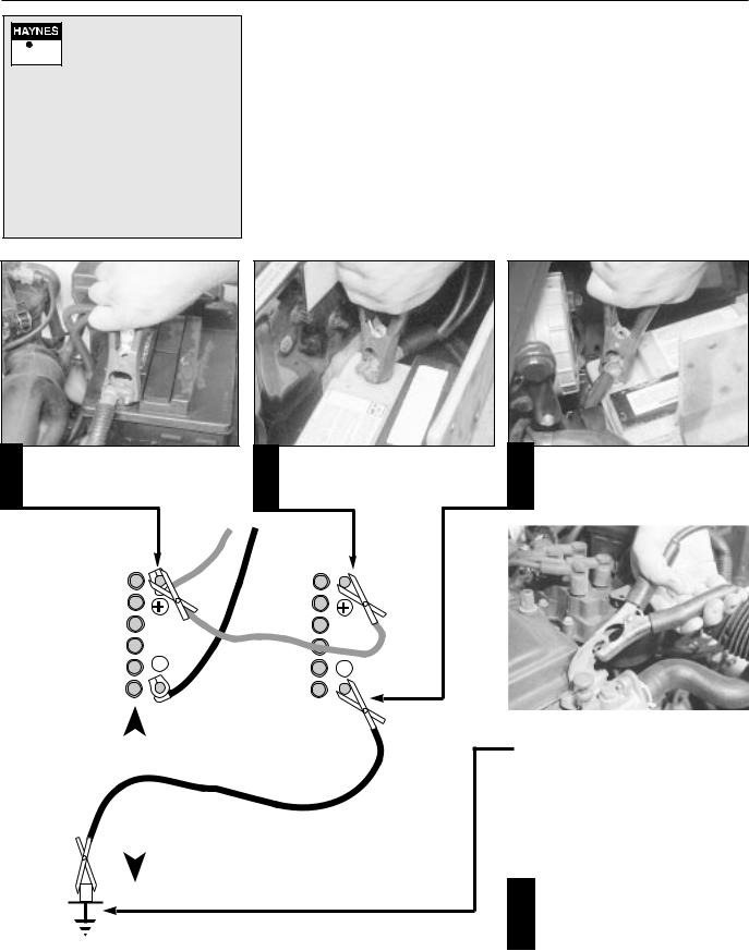
1
the positive (+) terminal of the flat battery
2 Connect the other end of the red lead to |
3 |
the positive (+) terminal of the booster battery.
to the negative (-) terminal of the booster battery
|
|
|
|
|
|
|
|
|
|
|
|
|
|
|
|
|
|
|
|
|
|
|
|
|
|
|
|
|
|
|
|
|
|
|
|
|
|
|
|
|
|
|
|
|
|
|
|
|
|
|
|
|
|
|
|
|
|
|
|
|
|
|
|
|
|
|
|
|
|
|
|
|
|
|
|
|
|
|
|
|
|
|
|
|
|
|
|
|
|
|
4 |
jump lead to a bolt or bracket on the |
|||
|
|||||||||||||||
|
|
|
|
|
|
|
|
|
|
|
|
|
|
|
engine block, well away from the |
|
|
|
|
|
|
|
|
|
|
|
|
|
|
|
battery, on the vehicle to be started. |
|
|
|
|
|
|
|
|
|
|
|
|
|
|
|
Make sure that the jump leads will not |
|
|
|
|
|
|
|
|
|
|
|
|
|
|
|
|
|
|
|
|
|
|
|
|
|
|
|
|
|
|
5 |
|
|
|
|
|
|
|
|
|
|
|
|
come into contact with the fan, drive- |
||||
|
|
|
|
|
|
|
|
|
|
|
|
|
|
|
belts or other moving parts of the |
|
|
|
|
|
|
|
|
|
|
|
|
|
|
|
engine. |
|
|
|
|
|
|
|
|
|
|
|
|
|
|
|
Start the engine using the booster |
|
|
|
|
|
|
|
|
|
|
|
|
|
|
|
|
|
6 |
||||||||||||||
|
battery, then with the engine running at |
||||||||||||||
|
|||||||||||||||
idle speed, disconnect the jump leads in the reverse order of connection.

0•8 Roadside repairs
Wheel changing
Some of the details shown here will vary according to model. For instance, the location of the spare wheel and jack is not the same on all cars. However, the basic principles apply to all vehicles.
Warning: Do not change a wheel in a situation where you risk being hit by other traffic. On busy roads, try to stop in a lay-by or a gateway. Be wary of passing traffic while changing the wheel – it is easy to become distracted by the job in hand.
Preparation
MWhen a puncture occurs, stop as soon as it is safe to do so.
MPark on firm level ground, if possible, and well out of the way of other traffic.
MUse hazard warning lights if necessary.
MIf you have one, use a warning triangle to alert other drivers of your presence.
MApply the handbrake and engage first or reverse gear.
MChock the wheel diagonally opposite the
one being removed – a couple of large stones will do for this.
MIf the ground is soft, use a flat piece of wood to spread the load under the foot of the jack.
Changing the wheel
1 Clear the boot area and remove the carpet.
4 Remove the wheel trim (where fitted) and slacken each wheel bolt by half a turn.
2 Remove the tool holder and unscrew the spare wheel clamp
5 Raise the jack whilst locating below the jacking point (ensure that the jack is on firm ground and located correctly)
3 For safety, place the spare wheel under the car near the jacking point.
6 Turn the handle clockwise until the wheel is raised clear of the ground. Remove the bolts and lift the wheel clear.
7 Position the spare wheel and fit the bolts. Hand tighten with the wheel brace and lower the car to the ground. Tighten
the wheel bolts in a diagonal sequence.
Finally...
MRefit the wheel trim (if applicable) and put the punctured wheel in the boot
MRemove the wheel chocks.
MStow the jack and tools in the correct locations in the car.
MCheck the tyre pressure on the wheel just fitted. If it is low, or if you don’t have a pressure gauge with you, drive slowly to the nearest garage and inflate the tyre to the right pressure.
MHave the damaged tyre or wheel repaired as soon as possible.
Puddles on the garage floor or drive, or obvious wetness under the bonnet or underneath the car, suggest a leak that needs investigating. It can sometimes be difficult to decide where the leak is coming from, especially if the engine bay is very dirty already. Leaking oil or fluid can also be blown rearwards by the passage of air under the car, giving a false impression of where the problem lies.
Roadside repairs 0•9
Identifying leaks
Warning: Most automotive oils and fluids are poisonous. Wash them off skin, and change out of contaminated clothing, without delay.
The smell of a fluid leaking from the car may provide a


 clue to what’s leaking. Some fluids are distinctively
coloured. It may help to clean the car carefully and to park it over some clean paper overnight as an aid to locating the source of the leak.
Remember that some leaks may only occur while the engine is running.
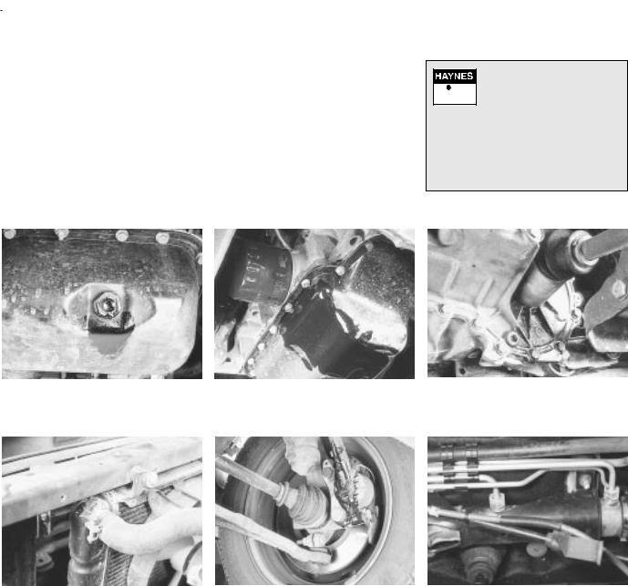
Sump oil |
|
Oil from filter |
|
Gearbox oil |
|
|
|
|
|
|
|
|
|
|
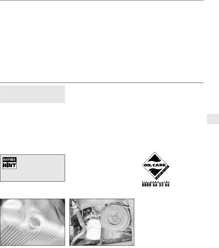
Engine oil may leak from the drain plug... |
...or from the base of the oil filter. |
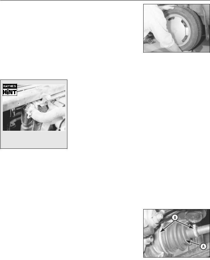
Gearbox oil can leak from the seals at the inboard ends of the driveshafts.
Antifreeze |
|
Brake fluid |
|
Power steering fluid |
|
|
|
|
|
|
|
|
|
|
Leaking antifreeze often leaves a crystalline deposit like this.
A leak occurring at a wheel is almost certainly brake fluid.
Power steering fluid may leak from the pipe connectors on the steering rack.
When all else fails, you may find yourself having to get a tow home – or of course you may be helping somebody else. Long-distance recovery should only be done by a garage or breakdown service. For shorter distances, DIY towing using another car is easy enough, but observe the following points:
MUse a proper tow-rope – they are not expensive. The vehicle being towed must display an ‘ON TOW’ sign in its rear window.
MAlways turn the ignition key to the ‘on’ position when the vehicle is being towed, so
that the steering lock is released, and that the direction indicator and brake lights will work.
MOnly attach the tow-rope to the towing eyes provided.
MBefore being towed, release the handbrake and select neutral on the transmission.
MNote that greater-than-usual pedal pressure will be required to operate the brakes, since the vacuum servo unit is only operational with the engine running.
MOn models with power steering, greater- than-usual steering effort will also be required.
Towing
MThe driver of the car being towed must keep the tow-rope taut at all times to avoid snatching.
MMake sure that both drivers know the route before setting off.
MOnly drive at moderate speeds and keep the distance towed to a minimum. Drive smoothly and allow plenty of time for slowing down at junctions.
MOn models with automatic transmission, special precautions apply. If in doubt, do not tow, or transmission damage may result.
0•10 Weekly checks
Introduction
There are some very simple checks which need only take a few minutes to carry out, but which could save you a lot of inconvenience and expense.
These "Weekly checks" require no great skill or special tools, and the small amount of time they take to perform could prove to be very well spent, for example;
MKeeping an eye on tyre condition and pressures, will not only help to stop them wearing out prematurely, but could also save your life.
MMany breakdowns are caused by electrical problems. Battery-related faults are particularly common, and a quick check on a regular basis will often prevent the majority of these.
MIf your car develops a brake fluid leak, the first time you might know about it is when your brakes don't work properly. Checking the level regularly will give advance warning of this kind of problem.
MIf the oil or coolant levels run low, the cost of repairing any engine damage will be far greater than fixing the leak, for example.
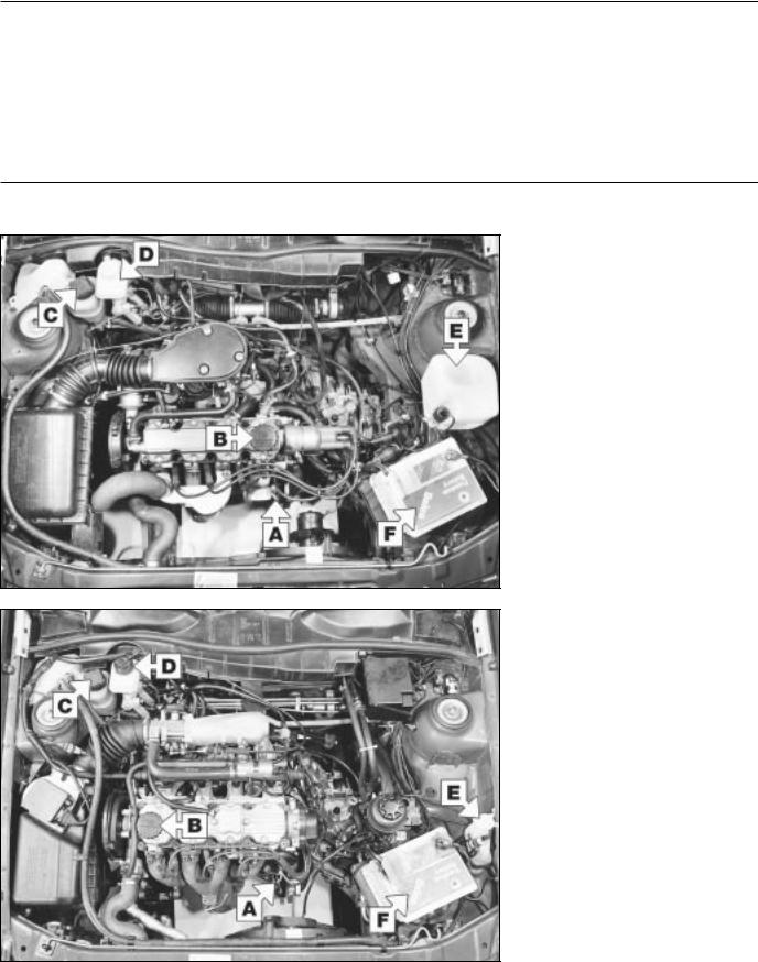
Underbonnet check points
§ 1.6 SV model
A Engine oil level dipstick
B Engine oil filler cap
C Coolant expansion cap
D Brake fluid reservoir
E Screen washer fluid reservoir
F Battery
§ 20 SEH model
A Engine oil level dipstick
B Engine oil filler cap
C Coolant expansion cap
D Brake fluid reservoir
E Screen washer fluid reservoir
F Battery
Weekly checks 0•11
§ C 20 XE model
A Engine oil level dipstick
B Engine oil filler cap
C Coolant expansion cap
D Brake fluid reservoir
E Screen washer fluid reservoir
F Battery
§ X 20 XEV model
A Engine oil level dipstick
B Engine oil filler cap
C Coolant expansion cap
D Brake fluid reservoir
E Screen washer fluid reservoir
F Battery

0•12 Weekly checks
Engine oil level
Before you start
Make sure that your car is on level ground.
Check the oil level before the car is driven, or at least 5 minutes after the engine has been switched off.
If the oil is checked
immediately after driving the
vehicle, some of the oil will remain in the upper engine
components, resulting in an inaccurate reading on the dipstick!
The correct oil
Modern engines place great demands on their oil. It is very important that the correct oil for your car is used (See “Lubricants and Fluids”).
Car Care
●If you have to add oil frequently, you should check whether you have any oil leaks. Place some clean paper under the car overnight, and check for stains in the morning. If there are no leaks, the engine may be burning oil
(see “Fault Finding”).
Always maintain the level between the upper and lower dipstick marks (see photo 3). If the level is too low severe engine damage may occur. Oil seal failure may result if the engine is overfilled by adding too much oil.
1 The dipstick is often brightly coloured for easy identification (see “Underbonnet
check points” on pages 0•10 and 0•11 for exact location. Withdraw the dipstick
3 Note the level on the end of the dipstick, which should be between the upper
(“MAX”) mark and lower (“MIN”) mark.
2 Using a clean rag or paper towel remove all oil from the dipstick. Insert the clean
dipstick into the tube as far as it will go, then withdraw it again.
4 Oil is added through the filler cap. Unscrew the cap and top-up the level. A
funnel may help to reduce spillage. Add the oil slowly, checking the level on the dipstick frequently. Avoid overfilling (see “Car Care”)
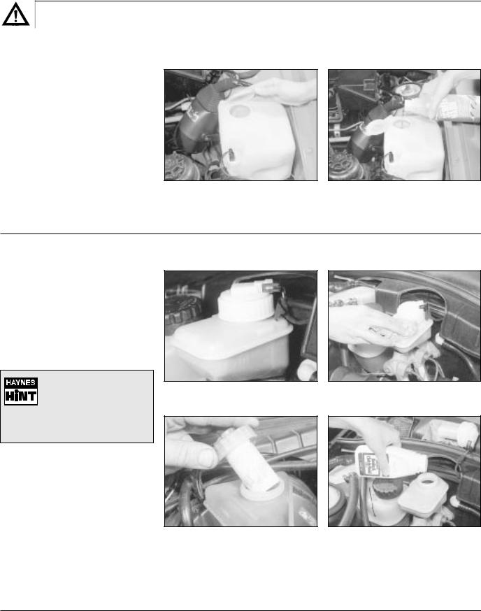
Coolant level
Warning: DO NOT attempt to remove the expansion tank pressure cap when the engine is hot, as there is a very great risk of scalding. Do not leave open containers of coolant about, as it is poisonous.
Car Care
● With a sealed-type cooling system, adding coolant should not be necessary on a regular basis. If frequent topping-up is required, it is likely there is a leak. Check the radiator, all hoses and joint faces for signs of staining or wetness, and rectify as necessary.
● It is important that antifreeze is used in the cooling system all year round, not just during the winter months. Don’t top-up with water alone, as the antifreeze will become too diluted.
1 |
The coolant level varies with the |
2 |
If topping-up is necessary, wait until the |
3 |
Add a mixture of water and antifreeze |
temperature of the engine. When the |
engine is cold. Slowly turn the expansion |
through the expansion tank filler neck |
|||
engine is cold, the coolant level should be |
tank cap anti-clockwise to relieve the system |
until the coolant reaches the “COLD” level |
|||
near the “COLD” (or “KALT”) mark. |
pressure. Once any pressure is released, turn |
mark. Refit the cap, turning it clockwise as far |
|||
|
|
the cap anti-clockwise unti it can be lifted off. |
as it will go until it is secure. |
||
|
|
|
|
|
|
Weekly checks 0•13
Screen washer fluid level
Screenwash additives not only keep the winscreen clean during foul weather, they also prevent the washer system freezing in cold weather - which is when you are likely to need it most. Don’t top up using plain water as the screenwash will become too diluted, and will freeze during cold weather. On no account use engine antifreeze in the washer system - this could discolour or damage paintwork.
1 The windscreen washer fluid reservoir is located in the rear left-hand corner of the engine compartment. The washer level can be seen through the reservoir body. If topping-up
is necessary, open the cap.
2 When topping-up the reservoir, add a screenwash additive in the quantities
recommended on the bottle.
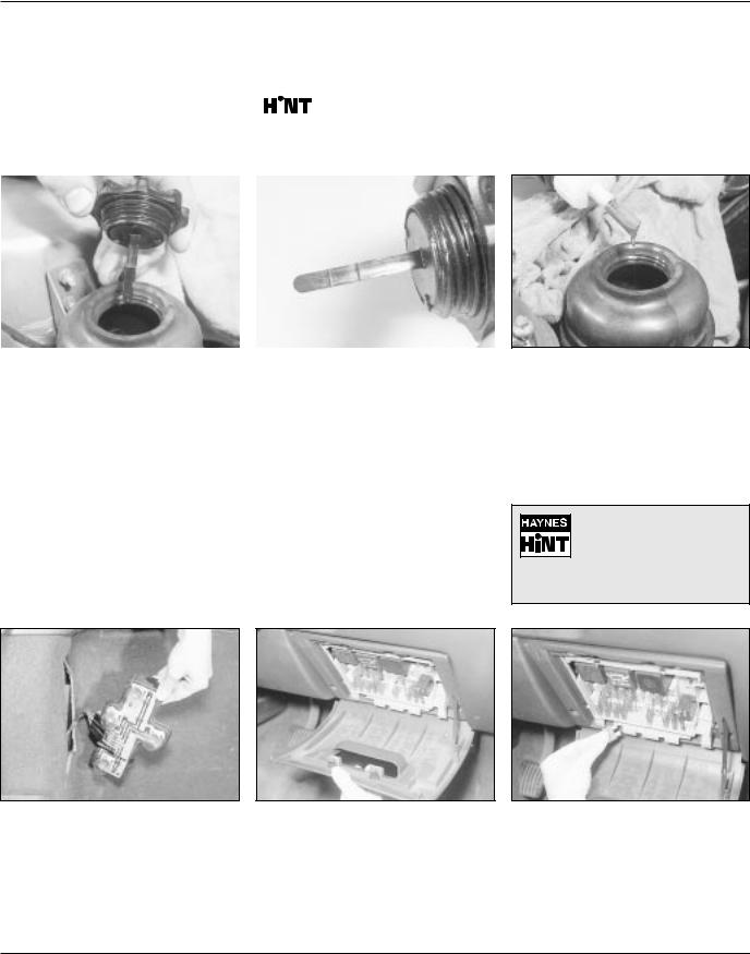
Brake fluid level
Warning:Brake hydraulic fluid can harm your eyes and damage painted surfaces, so use extreme caution when handling and pouring it.
● Do not use fluid that has been standing open for some time, as it absorbs moisture from the air which can cause a dangerous loss of braking effectiveness.
• Make sure that your car is on level ground.
• The fluid level in the master cylinder reservoir will
drop slightly as the brake pads wear down, but the fluid level must never be allowed to drop below the ‘MIN’ mark.
Safety first
●If the reservoir requires repeated toppingup this is an indication of a fluid leak somewhere in the system, which should be investigated immediately.
●If a leak is suspected, the car should not be driven until the braking system has been checked. Never take any risks where brakes are concerned.
1 The “MAX” and “MIN” marks are indicated on the side of the reservoir. The
fluid level must be kept between the marks.
3 When adding fluid, it’s a good idea to inspect the reservoir. The system should be drained and refilled if dirt is seen in the fluid
(see Chapter 9 for details).
2 If topping-up is necessary, first wipe the area around the filler cap with a clean rag
before removing the cap.
4 Carefully add fluid avoiding spilling it on surrounding paintwork. Use only the specified hydraulic fluid; mixing different types of fluid can cause damage to the system. After filling to the correct level, refit the cap securely, to prevent leaks and the entry of
foreign matter. Wipe off any spilt fluid.
0•14 Weekly checks
Power steering fluid level |
|
|||||
Before you start: |
|
|
|
|
|
|
|
|
|
|
For the check to be accurate |
||
Park the vehicle on level ground. |
|
|
|
|
||
|
|
|
|
the steering must not be |
||
|
|
|
|
|||
Set the steering wheel pointing straight- |
|
|
|
|
turned once the engine has |
|
|
|
|
|
|||
ahead. |
|
|
|
|
been stopped. |
|
|
|
|
|
|||
The engine should be turned off. |
|
|
|
|
|
|
|
|
|
|
|
||
|
|
|
|
|
|
|
|
|
|
|
|
|
|
Safety First:
The need for frequent topping-up indicates a leak, which should be investigated immediately.
1 |
The fluid level is checked with a dipstick |
2 |
Clean the area around the reservoir cap, |
3 |
If topping up is required, use the |
attached to the reservoir filler cap. The |
then unscrew the cap and wipe the |
specified type of fluid, and do not overfill |
|||
reservoir is located on the left-hand side of the |
dipstick with a clean rag. When the engine is |
the reservoir. When the level is correct, refit |
|||
engine compartment (veiwed from the drivers |
cold, the fluid should come up to the lower |
the cap. |
|||
seat) behind the battery. |
“ADD” mark; when hot, it should come up to |
|
|
||
|
|
the “FULL” mark. |
|
|
|
|
|
|
|
|
|
Electrical system
Check all external lights and the horn. Refer to the appropriate Sections of Chapter 12 for details if any of the circuits are found to be inoperative.
1 If a single indicator light, brake light or headlight has failed it is likely that a bulb has blown and will need to be replaced. Refer
to Chapter 12 for details.
If both brake lights have failed, it is possible that the brake light switch above the brake pedal needs adjusting. This simple operation is described in Chapter 9.
Visually check all wiring connectors, harnesses and retaining clips for security, and for signs of chafing or damage.
2 If more than one indicator light or headlight has failed it is likely that either a fuse has blown or that there is a fault in the circuit (refer to “Electrical fault-finding” in
Chapter 12).
The fuses are mounted in a panel located at the lower right-hand corner of the facia under a removable cover.
If you need to check your brake lights and indicators unaided, back up to a wall or garage door and operate
the lights. The reflected light should show if they are working properly.
3 To replace a blown fuse, simply pull it out. Fit a new fuse of the same rating,
available from car accessory shops.
It is important that you find the reason that the fuse blew - a checking procedure is given in Chapter 12.
Weekly checks 0•15
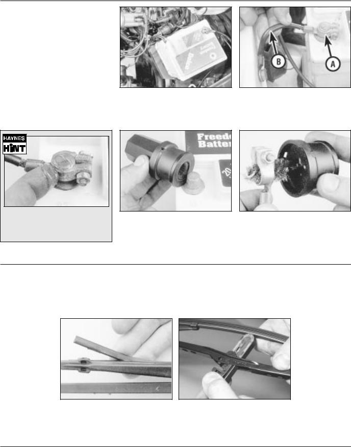
Battery
Caution: Before carrying out any work on the vehicle battery, read the precautions given in “Safety first” at the start of this manual.
Make sure that the battery tray is in good condition, and that the clamp is tight. Corrosion on the tray, retaining clamp and the battery itself can be removed with a solution of water and baking soda. Thoroughly rinse all cleaned areas with water. Any metal parts damaged by corrosion should be covered with a zinc-based primer, then painted.
Periodically (approximately every three months), check the charge condition of the battery as described in Chapter 5A.
If the battery is flat, and you need to jump start your vehicle, see “Roadside Repairs”.
Battery corrosion can be kept to a minimum by applying a layer of petroleum jelly to the clamps and terminals after they are reconnected.
1 The battery is located on the left-hand side of the engine compartment. The exterior of the battery should be inspected periodically for damage such as a cracked
case or cover.
3 If corrosion (white, fluffy deposits) is evident, remove the cables from the battery terminals, clean them with a small wire brush, then refit them. Accessory stores sell a
useful tool for cleaning the battery post ...
2 Check the tightness of battery clamps (A) to ensure good electrical connections.
You should not be able to move them. Also check each cable (B) for cracks and frayed conductors.
4 ... as well as the battery cable clamps
Wiper blades
1 Check the condition of the wiper blades; if they are cracked or show any signs of deterioration, or if the glass swept area is smeared, renew them. For maximum clarity of vision, wiper blades should be renewed
annually, as a matter of course.
2 To remove a wiper blade, pull the arm fully away from the glass until it locks.
Swivel the blade through 90°, press the locking tab(s) with your fingers, and slide the blade out of the arm's hooked end. On refitting, ensure that the blade locks securely into the arm.
0•16 Weekly checks
Tyre condition and pressure
It is very important that tyres are in good condition, and at the correct pressure - having a tyre failure at any speed is highly dangerous. Tyre wear is influenced by driving style - harsh braking and acceleration, or fast cornering, will all produce more rapid tyre wear. As a general rule, the front tyres wear out faster than the rears. Interchanging the tyres from front to rear (“rotating” the tyres) may result in more even wear. However, if this is completely effective, you may have the expense of replacing all four tyres at once!
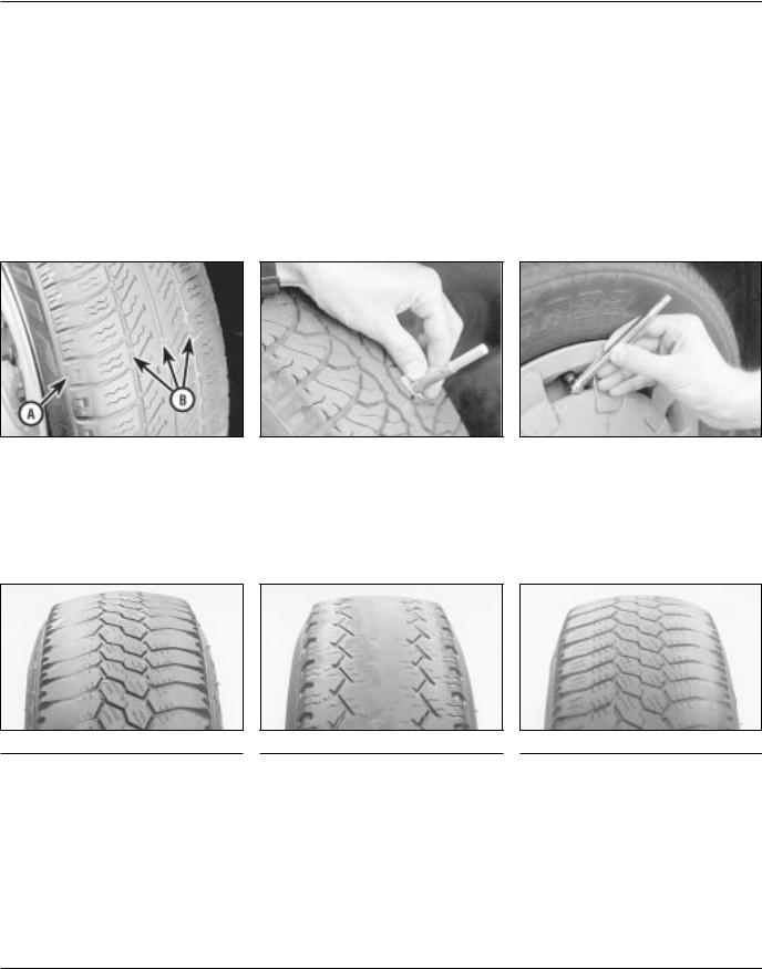
Remove any nails or stones embedded in the tread before they penetrate the tyre to cause deflation. If removal of a nail does reveal that
the tyre has been punctured, refit the nail so that its point of penetration is marked. Then immediately change the wheel, and have the tyre repaired by a tyre dealer.
Regularly check the tyres for damage in the form of cuts or bulges, especially in the sidewalls. Periodically remove the wheels, and clean any dirt or mud from the inside and outside surfaces. Examine the wheel rims for signs of rusting, corrosion or other damage. Light alloy wheels are easily damaged by “kerbing” whilst parking; steel wheels may also become dented or buckled. A new wheel is very often the only way to overcome severe damage.
New tyres should be balanced when they are fitted, but it may become necessary to rebalance them as they wear, or if the balance weights fitted to the wheel rim should fall off. Unbalanced tyres will wear more quickly, as will the steering and suspension components. Wheel imbalance is normally signified by vibration, particularly at a certain speed (typically around 50 mph). If this vibration is felt only through the steering, then it is likely that just the front wheels need balancing. If, however, the vibration is felt through the whole car, the rear wheels could be out of balance. Wheel balancing should be carried out by a tyre dealer or garage.
Tread Depth - visual check |
Tread Depth - manual check |
Tyre Pressure Check |
||||
|
The original tyres have tread wear safety |
|
Alternatively tread wear can be monitored |
|
Check the tyre pressures regularly with |
|
1 |
2 |
3 |
||||
bands (B), which will appear when the |
with a simple, inexpensive device known |
the tyres cold. Do not adjust the tyre |
||||
tread depth reaches approximately 1.6 mm. |
as a tread depth indicator gauge. |
pressures immediately after the vehicle has |
||||
The band positions are indicated by a |
|
|
been used, or an inaccurate setting will result. |
|||
triangular mark on the tyre sidewall (A). |
|
|
Tyre pressures are shown on the next page. |
|||
4 Tyre tread wear patterns
Shoulder Wear
Underinflation (wear on both sides)
Under-inflation will cause overheating of the tyre, because the tyre will flex too much, and the tread will not sit correctly on the road surface. This will cause a loss of grip and excessive wear, not to mention the danger of sudden tyre failure due to heat build-up.
Check and adjust pressures
Incorrect wheel camber (wear on one side)
Repair or renew suspension parts
Hard cornering
Reduce speed!
Centre Wear
Overinflation
Over-inflation will cause rapid wear of the centre part of the tyre tread, coupled with reduced grip, harsher ride, and the danger of shock damage occurring in the tyre casing.
Check and adjust pressures
If you sometimes have to inflate your car’s tyres to the higher pressures specified for maximum load or sustained high speed, don’t forget to reduce the pressures to normal afterwards.
Uneven Wear
Front tyres may wear unevenly as a result of wheel misalignment. Most tyre dealers and garages can check and adjust the wheel alignment (or "tracking") for a modest charge.
Incorrect camber or castor
Repair or renew suspension parts
Malfunctioning suspension
Repair or renew suspension parts
Unbalanced wheel
Balance tyres
Incorrect toe setting
Adjust front wheel alignment
Note: The feathered edge of the tread which typifies toe wear is best checked by feel.

Lubricants, fluids and tyre pressures 0•17
Lubricants and fluids
Component or system |
Lubricant type/specification |
Adhesive sealing compound . . . . . . . . . . . . . . . . . . . . . |
Vauxhall P/N 90485251 |
Automatic transmission . . . . . . . . . . . . . . . . . . . . . . . . . |
Dexron II type ATF(i.e. P/N 90350342) |
Braking system . . . . . . . . . . . . . . . . . . . . . . . . . . . . . . . |
Hydraulic fluid to SAE J1703F or DOT 4 |
|
(i.e. P/N 90007080) |
Cooling system . . . . . . . . . . . . . . . . . . . . . . . . . . . . . . . |
Ethylene glycol based antifreeze |
Engine . . . . . . . . . . . . . . . . . . . . . . . . . . . . . . . . . . . . . . |
Multigrade engine oil, viscosity SAE 10W/40 to |
|
20W/50, to API SG/CD |
Locking compound . . . . . . . . . . . . . . . . . . . . . . . . . . . . |
Vauxhall P/N 90167347 |
Long life grease . . . . . . . . . . . . . . . . . . . . . . . . . . . . . . |
Molybdenum disulphide grease (MoS2) |
Manual transmission . . . . . . . . . . . . . . . . . . . . . . . . . . . |
Gear oil, viscosity SAE 80 EP |
|
(i.e. Vauxhall P/N 90188629) |
Power steering . . . . . . . . . . . . . . . . . . . . . . . . . . . . . . . |
Dexron II type ATF (i.e. P/N 90350342) |
Sealing compound . . . . . . . . . . . . . . . . . . . . . . . . . . . . |
Vauxhall P/N 90094714 |
Silicone grease . . . . . . . . . . . . . . . . . . . . . . . . . . . . . . . |
Vauxhall P/N 90167353 |
Tyre pressures
|
Front |
Rear |
Early models (up to 1993 model year) |
|
|
1.4 and 1.6 litre models . . . . . . . . . . . . . . . . . . . . . . . . . |
27 psi (1.9 bar) |
24 psi (1.7 bar) |
2.0 litre 8-valve models . . . . . . . . . . . . . . . . . . . . . . . . . |
31.5 psi (2.2 bar) |
28.5 psi (2.0 bar) |
2.0 litre 16-valve models . . . . . . . . . . . . . . . . . . . . . . . . |
36 psi (2.5 bar) |
33 psi (2.3 bar) |
Later models (1993 model year onwards) |
|
|
1.6 litre models . . . . . . . . . . . . . . . . . . . . . . . . . . . . . . . |
28.5 psi (2.0 bar) |
26 psi (1.8 bar) |
1.8 litre models . . . . . . . . . . . . . . . . . . . . . . . . . . . . . . . |
31.5 psi (2.2 bar) |
28.5 psi (2.0 bar) |
2.0 litre models . . . . . . . . . . . . . . . . . . . . . . . . . . . . . . . |
34 psi (2.4 bar) |
31.5 psi (2.2 bar) |

Notes
1•1
Chapter 1
Routine maintenance and servicing
1
Contents
Air cleaner element - renewal . . . . . . . . . . . . . . . . . . . . . . . . . . . . . . .27 Air inlet temperature control check . . . . . . . . . . . . . . . . . . . . . . . . . .28 Alternator V-belt check . . . . . . . . . . . . . . . . . . . . . . . . . . . . . . . . . . . .22 Automatic transmission check . . . . . . . . . . . . . . . . . . . . . . . . . . . . . .34 Automatic transmission fluid level check . . . . . . . . . . . . . . . . . . . . . . .7 Automatic transmission fluid renewal . . . . . . . . . . . . . . . . . . . . . . . . .38 Bodywork check . . . . . . . . . . . . . . . . . . . . . . . . . . . . . . . . . . . . . . . . .20 Brake fluid renewal . . . . . . . . . . . . . . . . . . . . . . . . . . . . . . . . . . . . . . .14 Brake pad check . . . . . . . . . . . . . . . . . . . . . . . . . . . . . . . . . . . . . . . . .15 Brake shoe check . . . . . . . . . . . . . . . . . . . . . . . . . . . . . . . . . . . . . . . .35 Clutch cable check . . . . . . . . . . . . . . . . . . . . . . . . . . . . . . . . . . . . . . .32 Coolant renewal . . . . . . . . . . . . . . . . . . . . . . . . . . . . . . . . . . . . . . . . .26 Distributor and HT lead check . . . . . . . . . . . . . . . . . . . . . . . . . . . . . .31 Door lock key battery - replacement . . . . . . . . . . . . . . . . . . . . . . . . .24 Driveshaft gaiter check . . . . . . . . . . . . . . . . . . . . . . . . . . . . . . . . . . . . .6 Engine oil and filter - renewal . . . . . . . . . . . . . . . . . . . . . . . . . . . . . . . .3 Exhaust system check . . . . . . . . . . . . . . . . . . . . . . . . . . . . . . . . . . . .11 Fuel filter renewal . . . . . . . . . . . . . . . . . . . . . . . . . . . . . . . . . . . . . . . .29 Handbrake linkage check . . . . . . . . . . . . . . . . . . . . . . . . . . . . . . . . . .16
Headlamp alignment . . . . . . . . . . . . . . . . . . . . . . . . . . . . . . . . . . . . . |
.23 |
Hose and fluid leak check . . . . . . . . . . . . . . . . . . . . . . . . . . . . . . . . . |
.4 |
Idle speed and mixture - adjustment . . . . . . . . . . . . . . . . . . . . . . . . . |
.9 |
Ignition timing . . . . . . . . . . . . . . . . . . . . . . . . . . . . . . . . . . . . . . . . . . . |
13 |
Intensive maintenance . . . . . . . . . . . . . . . . . . . . . . . . . . . . . . . . . . . . |
.2 |
Introduction . . . . . . . . . . . . . . . . . . . . . . . . . . . . . . . . . . . . . . . . . . . . |
.1 |
Lock and hinge check . . . . . . . . . . . . . . . . . . . . . . . . . . . . . . . . . . . . |
21 |
Manual transmission fluid check . . . . . . . . . . . . . . . . . . . . . . . . . . . . |
33 |
Power steering fluid check . . . . . . . . . . . . . . . . . . . . . . . . . . . . . . . . . |
17 |
Power steering pump drivebelt check . . . . . . . . . . . . . . . . . . . . . . . . |
18 |
Radiator inspection and cleaning . . . . . . . . . . . . . . . . . . . . . . . . . . . . |
.8 |
Rear suspension level control system check . . . . . . . . . . . . . . . . . . . |
19 |
Road test . . . . . . . . . . . . . . . . . . . . . . . . . . . . . . . . . . . . . . . . . . . . . . |
25 |
Spark plug renewal (SOHC) . . . . . . . . . . . . . . . . . . . . . . . . . . . . . . . . |
30 |
Spark plug renewal (DOHC) . . . . . . . . . . . . . . . . . . . . . . . . . . . . . . . . |
37 |
Steering and suspension check . . . . . . . . . . . . . . . . . . . . . . . . . . . . . |
.5 |
Throttle linkage maintenance . . . . . . . . . . . . . . . . . . . . . . . . . . . . . . . |
10 |
Timing belt renewal . . . . . . . . . . . . . . . . . . . . . . . . . . . . . . . . . . . . . . . |
36 |
Wiring check . . . . . . . . . . . . . . . . . . . . . . . . . . . . . . . . . . . . . . . . . . . . |
12 |
Degrees of difficulty
|
|
|
|
|
|
|
|
|
|
|
|
|
|
|
Easy, suitable for |
1 |
|
Fairly easy, suitable |
2 |
|
Fairly difficult, |
3 |
|
Difficult, suitable for |
4 |
|
Very difficult, |
5 |
|
|
|
|
|
|
||||||||||
novice with little |
|
for beginner with |
|
suitable for competent |
|
experienced DIY |
|
suitable for expert DIY |
|
|||||
experience |
|
some experience |
|
DIY mechanic |
|
mechanic |
|
or professional |
|
|||||
|
|
|
|
|
|
|
|
|
|
|
|
|
|
|
|
|
|
|
|
|
|
|
|
|
|
|
|
|
|

1•2 Servicing Specifications
Lubricants and fluids
Refer to “Weekly Checks”
Capacities
Engine oil |
|
Including filter: |
|
1.4 litre . . . . . . . . . . . . . . . . . . . . . . . . . . . . . . . . . . . . . . . . . . . . . . . . |
3.0 litres |
1.6 litre . . . . . . . . . . . . . . . . . . . . . . . . . . . . . . . . . . . . . . . . . . . . . . . . |
3.5 litres |
1.8 and 2.0 litre SOHC models . . . . . . . . . . . . . . . . . . . . . . . . . . . . . . |
4.0 litres |
20 XEJ and C 20 XE . . . . . . . . . . . . . . . . . . . . . . . . . . . . . . . . . . . . . . |
4.5 litres |
X 20 XEV . . . . . . . . . . . . . . . . . . . . . . . . . . . . . . . . . . . . . . . . . . . . . . . |
4.0 litres |
Quantity of oil required to raise level on dipstick from “MIN” to “MAX”: |
|
1.4 litre . . . . . . . . . . . . . . . . . . . . . . . . . . . . . . . . . . . . . . . . . . . . . . . . |
0.8 litre |
All other models . . . . . . . . . . . . . . . . . . . . . . . . . . . . . . . . . . . . . . . . . |
1.0 litre |
Cooling system (approx.) |
|
1.4 litre models . . . . . . . . . . . . . . . . . . . . . . . . . . . . . . . . . . . . . . . . . . . . |
5.6 litres |
1.6 litre models (except C 16 NZ2) - manual transmission . . . . . . . . . . |
5.8 litres |
1.6 litre models (except C 16 NZ2) - automatic transmission . . . . . . . . |
5.6 litres |
C 16 NZ2, 1.8 and 2.0 litre SOHC models - manual transmission . . . . . |
7.2 litres |
C 16 NZ2, 1.8 and 2.0 litre SOHC models - automatic transmission . . . |
7.1 litres |
DOHC models . . . . . . . . . . . . . . . . . . . . . . . . . . . . . . . . . . . . . . . . . . . . . |
7.2 litres |
Transmission |
|
Manual transmission codes: |
|
F10 and F13 . . . . . . . . . . . . . . . . . . . . . . . . . . . . . . . . . . . . . . . . . . . . |
1.6 litres |
F16, F18 and F20 . . . . . . . . . . . . . . . . . . . . . . . . . . . . . . . . . . . . . . . . |
1.9 litres |
Automatic - at fluid change . . . . . . . . . . . . . . . . . . . . . . . . . . . . . . . . . . |
3.0 to 3.5 litres |
Difference between dipstick MAX and MIN marks - approximate: |
|
+ 20°C side . . . . . . . . . . . . . . . . . . . . . . . . . . . . . . . . . . . . . . . . . . . |
0.25 litre |
+ 80°C side . . . . . . . . . . . . . . . . . . . . . . . . . . . . . . . . . . . . . . . . . . . |
0.40 litre |
Power steering fluid |
|
Approximately . . . . . . . . . . . . . . . . . . . . . . . . . . . . . . . . . . . . . . . . . . . |
1.0 litre |
Fuel tank |
|
All models . . . . . . . . . . . . . . . . . . . . . . . . . . . . . . . . . . . . . . . . . . . . . . |
63.0 ± 2 litres |
Washer fluid |
|
Without headlamp washers . . . . . . . . . . . . . . . . . . . . . . . . . . . . . . . . |
2.6 litres |
With headlamp washers . . . . . . . . . . . . . . . . . . . . . . . . . . . . . . . . . . . |
4.5 litres |
Engine
Oil filter . . . . . . . . . . . . . . . . . . . . . . . . . . . . . . . . . . . . . . . . . . . . . . . . Champion G102
Cooling system
Antifreeze mixture: |
|
28% antifreeze . . . . . . . . . . . . . . . . . . . . . . . . . . . . . . . . . . . . . . . . . . |
Protection down to -15°C (5°F) |
50% antifreeze . . . . . . . . . . . . . . . . . . . . . . . . . . . . . . . . . . . . . . . . . . |
Protection down to -30°C (-22°F) |
Note: Refer to antifreeze manufacturer for latest recommendations. |
|
Fuel system
Note: Ignition timing adjustment is not possible on some models, shown for information only. For further details refer to Chapters 4A or 4B, as applicable.
Idle speed: |
|
|
14 NV . . . . . . . . . . . . . . . . . . . . . . . . . . . . . . . . . . . . . . . . . . . . . . . . . |
925 |
± 25 rpm |
16 SV |
|
|
Manual transmission models . . . . . . . . . . . . . . . . . . . . . . . . . . . . . |
925 |
± 25 rpm |
Automatic transmission models . . . . . . . . . . . . . . . . . . . . . . . . . . . |
825 |
± 25 rpm |
18 SV . . . . . . . . . . . . . . . . . . . . . . . . . . . . . . . . . . . . . . . . . . . . . . . . . . |
925 |
± 25 rpm |
C 16 NZ and X 16 SZ . . . . . . . . . . . . . . . . . . . . . . . . . . . . . . . . . . . . . |
850 |
± 80 rpm |
C 16 NZ2 . . . . . . . . . . . . . . . . . . . . . . . . . . . . . . . . . . . . . . . . . . . . . . . |
880 |
± 80 rpm |
C 18 NZ |
|
|
Manual transmission models . . . . . . . . . . . . . . . . . . . . . . . . . . . . . |
880 |
± 80 rpm |
Automatic transmission models . . . . . . . . . . . . . . . . . . . . . . . . . . . |
830 |
± 80 rpm |
20 NE, C 20 NE and 20 SEH . . . . . . . . . . . . . . . . . . . . . . . . . . . . . . . . |
800 |
± 80 rpm |
20 XEJ and C 20 XE . . . . . . . . . . . . . . . . . . . . . . . . . . . . . . . . . . . . . . |
940 |
± 80 rpm |
X 20 XEV . . . . . . . . . . . . . . . . . . . . . . . . . . . . . . . . . . . . . . . . . . . . . . . |
850 |
± 160 rpm |
|
Servicing Specifications 1•3 |
Idle mixture CO content: |
|
All carburettor models . . . . . . . . . . . . . . . . . . . . . . . . . . . . . . . . . . . . |
0.5 to 1.5% |
20 NE and 20 SEH . . . . . . . . . . . . . . . . . . . . . . . . . . . . . . . . . . . . . . . |
1.0 max. |
20 XEJ . . . . . . . . . . . . . . . . . . . . . . . . . . . . . . . . . . . . . . . . . . . . . . . . . |
0.7 to 1.2% |
All other injection models . . . . . . . . . . . . . . . . . . . . . . . . . . . . . . . . . . |
0.3 % (at 2800 to 3200 rpm) |
Air filter element: |
|
1.4 and 1.6 litre ‘round type’ . . . . . . . . . . . . . . . . . . . . . . . . . . . . . . . . |
Champion W103 |
1.6 and 1.8 litre ‘square type’ . . . . . . . . . . . . . . . . . . . . . . . . . . . . . . . |
Champion U512 |
1.8 litre ‘round type’ . . . . . . . . . . . . . . . . . . . . . . . . . . . . . . . . . . . . . . |
Champion type not available |
2.0 litre . . . . . . . . . . . . . . . . . . . . . . . . . . . . . . . . . . . . . . . . . . . . . . . . |
Champion U554 |
Fuel filter: |
|
1.6, 1.8 and 2.0 litre ‘in-line’ . . . . . . . . . . . . . . . . . . . . . . . . . . . . . . . . |
Champion L201 |
Ignition system: |
|
Ignition timing . . . . . . . . . . . . . . . . . . . . . . . . . . . . . . . . . . . . . . . . . . . |
Refer to Chapter 5 |
Spark plugs |
|
SOHC models . . . . . . . . . . . . . . . . . . . . . . . . . . . . . . . . . . . . . . . . . . . |
Champion RN9YCC or RN9YC |
DOHC models: |
|
except C20 XE and X20 XEV . . . . . . . . . . . . . . . . . . . . . . . . . . . . . |
Champion RC9MCC * |
C20 XE and X20 XEV . . . . . . . . . . . . . . . . . . . . . . . . . . . . . . . . . . . |
Vauxhall P/N 90444724 (FR8LDC) |
Plug gap: |
|
RN9YCC and RC9MCC * . . . . . . . . . . . . . . . . . . . . . . . . . . . . . . . . . . |
0.8 mm |
RN9YC * . . . . . . . . . . . . . . . . . . . . . . . . . . . . . . . . . . . . . . . . . . . . . . . |
0.7 mm |
FR8LDC . . . . . . . . . . . . . . . . . . . . . . . . . . . . . . . . . . . . . . . . . . . . . . . |
0.7 to 0.8 mm |
* Information on spark plug types and electrode gaps is as recommended by Champion Spark Plug. Where alternative types are used, refer to the |
||||
manufacturer’s recommendations |
|
|
|
|
Brakes |
|
|
|
|
Minimum pad friction material thickness (including backing plate): |
|
|
|
1 |
All models |
7.0 mm |
|
|
|
|
|
|
||
Minimum shoe friction material thickness: |
|
|
|
|
All models . . . . . . . . . . . . . . . . . . . . . . . . . . . . . . . . . . . . . . . . . . . . . . |
0.5 mm above rivet heads |
|||
Tyres |
|
|
|
|
Tyre size: |
|
|
|
|
51/2 J x 13 wheels . . . . . . . . . . . . . . . . . . . . . . . . . . . . . . . . . . . . . . . |
165 R13-82T |
|
|
|
51/2 J x 14 wheels . . . . . . . . . . . . . . . . . . . . . . . . . . . . . . . . . . . . . . . |
175/70 R14-82T, 195/60 R14-85H, or 195/60 R14-85V |
|||
6J x 15 wheels . . . . . . . . . . . . . . . . . . . . . . . . . . . . . . . . . . . . . . . . . . |
195/60 R15-87V or 205/55 R15-87V |
|||
Pressures |
See “Weekly checks” |
|
|
|
Torque wrench settings |
Nm |
lbf ft |
||
Automatic transmission drain plug . . . . . . . . . . . . . . . . . . . . . . . . . . . . . |
45 |
33 |
|
|
Roadwheel . . . . . . . . . . . . . . . . . . . . . . . . . . . . . . . . . . . . . . . . . . . . . . . |
110 |
81 |
|
|
Spark plugs . . . . . . . . . . . . . . . . . . . . . . . . . . . . . . . . . . . . . . . . . . . . . . . |
25 |
18 |
|
|
Engine oil (sump) drain plug . . . . . . . . . . . . . . . . . . . . . . . . . . . . . . . . . |
55 |
41 |
|
|
|
|
|
|
|
Maintenance schedule
The maintenance intervals in this manual are provided with the assumption that you, not the dealer, will be carrying out the work. These are the minimum maintenance intervals recommended by the manufacturer for vehicles driven daily. If you wish to keep your vehicle in peak condition at all times, you may wish to perform some of these procedures more often. We encourage frequent maintenance, because it enhances the efficiency, performance and resale value of your vehicle.
If the vehicle is driven in dusty areas, used to tow a trailer, or driven frequently at slow speeds (idling in traffic) or on short journeys,
more frequent maintenance intervals are recommended. Vauxhall recommend that the service intervals are halved for vehicles that are used under these conditions.
When the vehicle is new, it should be serviced by a factory-authorised dealer service department, to preserve the factory warranty.
Maintenance is essential for ensuring safety and for getting the best in terms of performance and economy from your vehicle. Over the years, the need for periodic lubrication - oiling, greasing, and so on - has been drastically reduced, if not eliminated. This has unfortunately tended to lead some
owners to think that because no action is required, components either no longer exist, or will last for ever. This is certainly not the case; it is essential to carry out regular visual examination comprehensively to spot any possible defects at an early stage before they develop into major expensive repairs.
The following service schedules are a list of the maintenance requirements, and the intervals at which they should be carried out, as recommended by the manufacturers. Where applicable, these procedures are covered in greater detail near the beginning of each relevant Chapter.

1•4 Maintenance schedule
Every 250 miles (400 km) or weekly
M Refer to “Weekly checks”
Basic service, every 9000 miles (15 000 km) or 12 months - whichever comes sooner
Along with the items in “Weekly checks”, carry out the following:
MRenew the engine oil and oil filter (Section 3).
MCheck all hoses and other components for fluid leaks (Section 4).
MCheck the steering and suspension components (Section 5).
MCheck the condition of the driveshaft rubber gaiters (Section 6).
MCheck the automatic transmission fluid level (if applicable), (Section 7).
MCheck the radiator for blockage (e.g. dead insects) and clean as necessary (Section 8).
MCheck and adjust the idle speed and mixture (if applicable), (Section 9).
MCheck the throttle linkage and lubricate if necessary (Section 10).
MCheck the exhaust system for corrosion, leaks and security (Section 11).
MCheck all wiring for condition and security (Section 12).
MCheck and adjust the ignition timing (if applicable), (Section 13).
MRenew the brake fluid (Section 14).
MCheck the brake pad friction material for wear (Section 15).
MCheck the handbrake linkage (Section 16).
MCheck the power steering fluid level (if applicable), (Section 17).
MCheck the power steering pump drivebelt (if applicable), (Section 18).
MCheck the rear suspension level control system height, if fitted (Section 19).
MCheck the bodywork (Section 20).
MLubricate all locks and hinges (Section 21).
MCheck the alternator V-belt (Section 22).
MCheck the headlamp alignment (Section 23).
MReplace battery in the door-lock key (if applicable), (Section 24).
MCarry out a road test (Section 25).
Note: Vauxhall specify that an Exhaust Emissions Test should be carried out at least annually. However, this requires special equipment, and is performed as part of the MOT test (refer to the end of the manual).
Full service, every 18 000 miles (30 000 km) or 24 months - whichever comes sooner
Along with the ‘basic service’, carry out the following:
MRenew the coolant (Section 26).
MRenew the air cleaner element (Section 27).
MCheck the operation of the air cleaner air inlet temperature control (carburettor models only), (Section 28).
MRenew the fuel filter (Section 29).
MRenew the spark plugs (SOHC only), (Section 30) *.
MInspect and clean the distributor cap and HT leads (Section 31).
MCheck the clutch cable adjustment (Section 32).
MCheck the manual transmission oil level (Section 33).
MCheck the automatic transmission (Section 34).
MCheck the brake drum shoe for wear (Section 35).
Major service, every 36 000 miles (60 000 km) or 48 months - whichever comes sooner
Along with the ‘full service’, carry out the following:
MRenew timing belt (Section 36).
MRenew the spark plugs (DOHC models only), (Section 37).
MRenew automatic transmission fluid (Section 38) *.
* Note: If a vehicle is used for heavy-duty work (e.g. taxi work, caravan/trailer towing, mostly short-distance, stop-start city driving) the fluid must be changed every 36 months or 27 000 miles (45 000 km), whichever occurs first.

Maintenance - component location 1•5
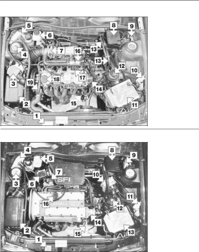
Underbonnet view of a 1989 1.6 L model (16 SV engine)
1VIN plate
2Air cleaner casing *
3Suspension strut top
4Coolant expansion tank
5Brake fluid reservoir
6Fuel pump
7Steering rack
8Octane rating plug
9Washer fluid reservoir
10Battery
11Ignition coil
12Distributor (Bosch type)
13Cooling fan motor
14Engine oil level dipstick
15Oil filter
16Oil filler cap
*Refer to Chapter 4A for alternative type
1
Underbonnet view of a 1991 model Cavalier 1.6 L (C16 NZ engine)
1Air cleaner casing
2Suspension strut top
3Coolant expansion tank
4Brake fluid reservoir
5Air box
6Exhaust gas recirculation valve
7Steering gear
8Octane coding plug
9Washer fluid reservoir
10Battery
11Ignition coil
12Distributor
13Cooling fan motor
14Engine oil level dipstick
15Engine oil filter
16Oxygen sensor
17Engine oil filler cap
1•6 Maintenance - component location
Underbonnet view of a 1989 2.0 SRi model (20 SEH engine)
1 VIN plate
2 Air cleaner casing
3 Airflow meter
4 Suspension strut top
5 Coolant expansion tank
6 Brake fluid reservoir
7 Throttle body
8 Relay box
9 Octane rating plug
10 Washer fluid reservoir
11 Battery
12 Power steering fluid reservoir
13 Power steering fluid hoses
14 Distributor cap
15 Engine oil level dipstick
16 Idle speed adjuster
17 Fuel pressure regulator
18 Oil filler cap
19 Thermostat housing
Underbonnet view of a 1990 GSi 2000 model (20 XEJ engine)
1 VIN plate
2 Air cleaner casing
3 Suspension strut top
4 Coolant expansion tank
5 Brake fluid reservoir
6 Air mass meter
7 Fuel pressure regulator
8 Relay box
9 Anti-theft alarm horn
10 ABS hydraulic modulator
11 Washer fluid reservoir
12 Power steering fluid reservoir
13 Battery
14 Distributor
15 Engine oil level dipstick
16 Oil filler cap
Maintenance - component location 1•7
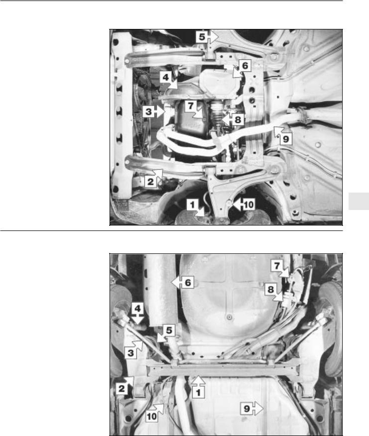
Front underbody view of a 1989 1.6 L model (16 SV engine)
1Brake caliper
2Subframe
3Oil filter
4Clutch cover plate
5Suspension lower arm
6Differential cover plate
7Engine oil drain plug
8Driveshaft gaiter
9Exhaust pipe
10Anti-roll bar securing nut
1
Rear underbody view of a 1989 2.0 SRi model (semi-independent rear suspension)
1Torsion beam
2Trailing arm
3Anti-roll bar
4Shock absorber
5Coil spring
6Exhaust expansion box
7Fuel flow damper
8Fuel filter
9Fuel tank securing strap
10Handbrake cable

1•8 Maintenance - component location
Rear underbody view of a 1990 GSi 2000 model (fully independent rear suspension)
1 Fuel tank securing strap
2 Shock absorber
3 ABS wheel sensor
4 Semi-trailing arm
5 Suspension crossmember mounting bracing bracket
6 Handbrake cable
7 Suspension crossmember
8 Exhaust expansion box
9 Fuel pump
Maintenance procedures
1 Introduction
This Chapter is designed to help the home mechanic maintain his/her vehicle for safety, economy, long life and peak performance.
The Chapter contains a master maintenance schedule, followed by Sections dealing specifically with each task in the schedule. Visual checks, adjustments, component renewal and other helpful items are included. Refer to the accompanying illustrations of the engine compartment and the underside of the vehicle for the locations of the various components.
Servicing your vehicle according to the mileage/time maintenance schedule and the following Sections will provide a planned maintenance programme, which should result in a long and reliable service life. This is a comprehensive
plan, so maintaining some items but not others at the specified service intervals, will not produce the same results.
As you service your vehicle, you will discover that many of the procedures can - and should - be grouped together, because of the particular procedure being performed, or because of the proximity of two otherwiseunrelated components to one another. For example, if the vehicle is raised for any reason, the exhaust can be inspected at the same time as the suspension and steering components.
The first step in this maintenance programme is to prepare yourself before the actual work begins. Read through all the Sections relevant to the work to be carried out, then make a list and gather all the parts and tools required. If a problem is found, seek advice from a parts specialist, or a dealer service department.
2 Intensive maintenance
If, from the time the vehicle is new, routine maintenance schedule is followed closely, frequent checks made of fluid levels and highwear items, as recommended, the engine will be kept in relatively good running condition. The need for additional work will be minimised
It is possible that there will be times when the engine is running poorly due to the lack of regular maintenance. This is even more likely if a used vehicle, which has not received regular and frequent maintenance checks, is purchased. In such cases, additional work may need to be carried out, outside of the regular maintenance intervals.
If engine wear is suspected, a compression
Every 9000 miles or 12 months 1•9
test (refer to Chapter 2A) will provide valuable information regarding the overall performance of the main internal components. Such a test can be used as a basis to decide on the extent of the work to be carried out. If, for example, a compression test indicates serious internal engine wear, conventional maintenance as described in this Chapter will not greatly improve the performance of the engine. It may also prove a waste of time and money, unless extensive overhaul work is carried out first.
The following series of operations are those most often required to improve the performance of a generally poor-running engine:
Primary operations
a)Clean, inspect and test the battery (See “Weekly Checks”)
b)Check all the engine related fluids (See “Weekly Checks”)
c)Check the condition and tension of the auxiliary drivebelt (Sections 18 and 22, as appropriate).
d)Renew the spark plugs (Sections 30 and 37, as appropriate).
e)Inspect the distributor cap, rotor arm and HT leads, as applicable (Section 31).
f)Check the condition of the air filter, and renew if necessary (Section 27).
g)Check the fuel filter (Section 29).
h)Check the condition of all hoses, and check for fluid leaks (Section 4).
i) Check the idle speed and mixture settings, as applicable (Section 9).
5 If the above operations do not prove fully effective, carry out the following secondary operations:
Secondary operations
All items listed under “Primary operations”, plus the following:
a)Check the charging system (Chapter 5).
b)Check the ignition system (Chapter 5).
c)Check the fuel system (Chapters 4A and 4B).
d)Renew the distributor cap and rotor arm (Section 31).
e)Renew the ignition HT leads (Section 31).
Basic service, every 9000 miles (15 000 km) or 12 months
3 Engine oil and filter - renewal 2
1Ideally, the oil should be drained with the engine hot, just after the vehicle has been driven.
2On DOHC models, remove the engine undershield to expose the sump drain plug and the oil filter.
3Place a container beneath the oil drain plug at the rear of the sump.
4Remove the oil filler cap from the camshaft cover, then using a socket or spanner, unscrew the oil drain plug, and allow the oil to drain (see illustration). Take care to avoid scalding if the oil is hot.
As the drain plug releases from the threads, move it
away quickly so the stream of oil, running out of the
sump, goes into the container not up your sleeve (see illustration).
5 Allow ten to fifteen minutes for the oil to drain completely, then move the container and position it under the oil filter.
6 On 1.8 and 2.0 litre models, improved access to the oil filter can be gained by jacking up the front of the vehicle and removing the right-hand roadwheel (see illustration). Ensure that the handbrake is applied, and that the vehicle is securely supported on axle stands (see “Jacking and Vehicle Support”). Note that further oil may drain from the sump as the vehicle is raised.
7Using a strap wrench or a filter removal tool if necessary, slacken the filter and unscrew it from the mounting. Alternatively, if the filter is very tight, a screwdriver can be driven through the filter casing and used as a lever. Discard the filter.
8Wipe the mating face on the filter mounting with a lint-free rag, then smear the sealing ring of the new filter with clean engine oil of the specified grade.
9Screw the new filter into position and tighten it by hand only, do not use any tools.
10Where applicable, refit the roadwheel and lower the vehicle to the ground. Fully tighten the roadwheel bolts with the vehicle resting on its wheels.
11Examine the condition of the oil drain plug sealing ring and renew if necessary, then refit the drain plug and tighten it to the specified torque.
12 Refill the engine through the filler on the |
|
camshaft cover, using the specified grade and |
|
quantity of oil. Fill until the level reaches the |
|
“MAX” mark on the dipstick, allowing time for |
|
the oil to drain through the engine to the |
|
sump. |
|
13 Refit the oil filler cap, then start the engine |
|
and check for leaks. Note that the oil pressure |
|
warning lamp may stay illuminated for a few |
1 |
seconds when the engine is started as the oil |
filter fills with oil.
14Stop the engine and recheck the oil level, topping-up if necessary.
15On DOHC models, refit the engine undershield.
16Dispose of the old engine oil safely; do not pour it down a drain.
Note: It is antisocial and illegal to dump oil down the drain. To find the location of your local oil recycling bank, call this number free.
4 Hose and fluid leak check |
1 |
|
|
3.4 Sump drain plug location - |
3.6 Oil filter viewed through right-hand |
2.0 litre DOHC model |
wheel arch - SOHC model |
(engine undershield removed) |
|
1 Visually inspect the engine joint faces, gaskets and seals for any signs of water or oil leaks. Pay particular attention to the areas around the camshaft cover, cylinder head, oil filter and sump joint faces. Remember that, over a period of time, some very slight seepage from these areas is to be expected - what you are really looking for is any indication of a serious leak. Should a leak be found, renew the offending gasket or oil seal by referring to the appropriate Chapters in this manual.
1•10 Every 9000 miles or 12 months
2Also check the security and condition of all the engine related pipes and hoses. Ensure that all cable-ties or securing clips are in place, and in good condition. Clips that are broken or missing can lead to chafing of the hoses, pipes or wiring, which could cause more serious problems in the future.
3Carefully check the radiator hoses and heater hoses along their entire length. Renew any hose that is cracked, swollen or deteriorated. Cracks will show up better if the hose is squeezed. Pay close attention to the hose clips that secure the hoses to the cooling system components. Hose clips can pinch and puncture hoses, resulting in cooling system leaks. It is always beneficial to renew hose clips whenever possible.
4Inspect all the cooling system components (hoses, joint faces, etc.) for leaks.
A leak in the cooling system will usually show up as white or rust coloured deposits on the area adjoining the leak
5Where any problems are found on system components, renew the component or gasket with reference to Chapter 3.
6Where applicable, inspect the automatic transmission fluid cooler hoses for leaks or deterioration.
7With the vehicle raised, inspect the petrol tank and filler neck for punctures, cracks and other damage. The connection between the filler neck and tank is especially critical. Sometimes a rubber filler neck or connecting hose will leak due to loose retaining clamps or deteriorated rubber.
8Carefully check all rubber hoses and metal fuel lines leading away from the petrol tank. Check for loose connections, deteriorated hoses, crimped lines, and other damage. Pay particular attention to the vent pipes and hoses, which often loop up around the filler neck and can become blocked or crimped. Follow the lines to the front of the vehicle, carefully inspecting them all the way. Renew damaged sections as necessary.
9From within the engine compartment, check the security of all fuel hose attachments and pipe unions, and inspect the fuel hoses and vacuum hoses for kinks, chafing and deterioration.
10Where applicable, check the condition of the power steering fluid hoses and pipes.
5 Steering and suspension |
2 |
check |
|
|
|
Front suspension and steering check
1Raise the front of the car, and support on axle stands (“Jacking and Vehicle Support”).
2Visually inspect the balljoint dust covers and the steering rack-and-pinion gaiters for splits, chafing or deterioration. Any wear of these components will cause loss of lubricant, together with dirt and water entry, resulting in rapid wear of the balljoints or steering gear.
3On vehicles with power steering, check the fluid hoses for chafing or deterioration, and the pipe and hose unions for fluid leaks. Also check for signs of fluid leakage under pressure from the steering gear rubber gaiters, which would indicate failed fluid seals within the steering gear.
4Grasp the roadwheel at the 12 o’clock and
6o’clock positions, and try to rock it (see illustration). Very slight free play may be felt, but if the movement is appreciable, further investigation is necessary to determine the source. Continue rocking the wheel while an assistant depresses the footbrake. If the movement is now eliminated or significantly reduced, it is likely that the hub bearings are at fault. If the free play is still evident with the footbrake depressed, then there is wear in the suspension joints or mountings.
5Now grasp the wheel at the 9 o’clock and 3 o’clock positions, and try to rock it as before. Any movement felt now may again be caused by wear in the hub bearings or the steering track-rod balljoints. If the inner or outer balljoint is worn, the visual movement will be obvious.
6Using a large screwdriver or flat bar, check for wear in the suspension mounting bushes by levering between the relevant suspension component and its attachment point. Some movement is to be expected as the mountings are made of rubber, but excessive wear should be obvious. Also check the condition of any visible rubber bushes, looking for splits, cracks or contamination of the rubber.
7Inspect the front suspension lower arms for distortion or damage (Chapter 10, Section 5).
8With the car standing on its wheels, have an assistant turn the steering wheel back and forth about an eighth of a turn each way. There should be very little, if any, lost movement between the steering wheel and roadwheels. If this is not the case, closely observe the joints and mountings previously described, but in addition, check the steering column universal joints for wear, and the rack- and-pinion steering gear itself.
Suspension strut/shock absorber check
Note: Suspension struts/shock absorbers should always be renewed in pairs on the same axle.
5.4 Check for wear in the hub bearings by grasping the wheel and trying to rock it
9Check for any signs of fluid leakage around the suspension strut/shock absorber body, or from the rubber gaiter around the piston rod. Should any fluid be noticed, the suspension strut/shock absorber is defective internally, and should be renewed.
10The efficiency of the suspension strut/shock absorber may be checked by bouncing the vehicle at each corner. The body will return to its normal position and stop after being depressed. If it rises and returns on a rebound, the suspension strut/shock absorber is probably suspect. Examine also the suspension strut/shock absorber upper and lower mountings for any signs of wear.
6 Driveshaft gaiter check |
2 |
|
|
With the vehicle raised and securely supported on stands, turn the steering onto full lock, then slowly rotate the roadwheel. Inspect the condition of the outer constant velocity (CV) joint rubber gaiters, squeezing the gaiters to open out the folds (see illustration). Check for signs of cracking, splits or deterioration of the rubber, which may allow the grease to escape, and lead to water and grit entry into the joint. Also check the security and condition of the retaining clips. Repeat these checks on the inner CV joints. If any damage or deterioration is found, the gaiters should be renewed as described in Chapter 8.
6.1 Check the condition of the driveshaft gaiters (A) and clips (B)
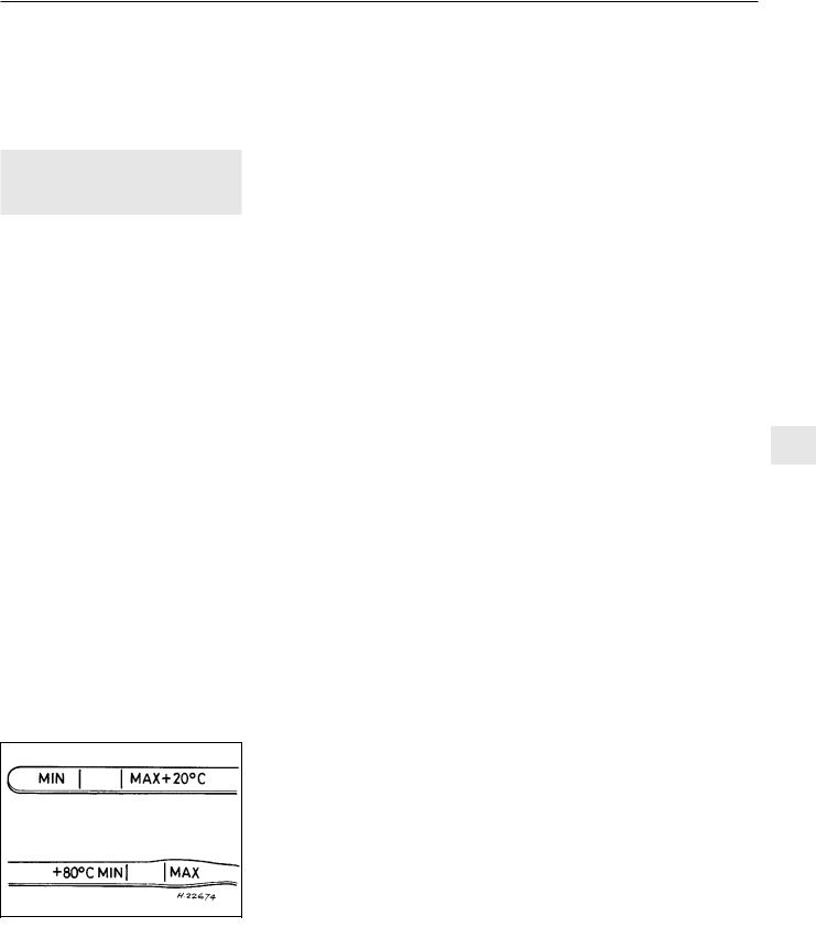
Every 9000 miles or 12 months 1•11
At the same time, check the general condition of the CV joints themselves by first holding the driveshaft and attempting to rotate the wheel. Repeat this check by holding the inner joint and attempting to rotate the driveshaft. Any appreciable movement indicates wear in the joints, wear in the driveshaft splines, or a loose driveshaft retaining nut.
7Automatic transmission fluid 2 level check
Note: The transmission fluid level can be checked either when it is cold (only below 35ºC (100ºF) outside temperature) or when it is fully warmed up to normal operating temperature (after driving for a distance of approximately 12 miles/20 km). Since the fluid level must be checked with the engine running, ensure that the vehicle is parked on level ground with the handbrake firmly applied before leaving the driver’s seat. Be careful to keep loose clothing, long hair, etc., well clear of hot or moving components when working under the bonnet
Transmission cold
1Park the vehicle on level ground and apply the handbrake firmly. With the engine running at no more than idle speed and your foot firmly on the brake pedal, move the selector lever through all positions, ending in position “P”. Allow the engine to idle for one minute, then check the level within two minutes.
2With the engine still idling and position “P” still selected, open the bonnet and withdraw the transmission dipstick from the filler tube located in the front of the transmission casing, at the left-hand end of the engine.
3Note the fluid’s condition (see below), then wipe clean the dipstick using a clean, non-fluffy rag, insert it fully back into the tube and withdraw it again.
4The level should be up to the “MAX” mark on the “+20°C” side of the dipstick (see illustration).
5If topping-up is required, switch off the ignition and add only good quality fluid of the specified type through the filler tube. If
7.4 When checking the fluid level, ensure side of dipstick used corresponds with fluid temperature
significant amounts of fluid are being lost (carefully note the amounts being added, and how often), check the transmission for leaks and either repair the fault or take the vehicle to a Vauxhall dealer for attention.
6 When the level is correct, ensure that the dipstick is pressed firmly into the filler tube.
Transmission fully warmed up
7 Work exactly as described above, but take the level reading from the “+ 80°C” side of the dipstick. In this case, the level must be between the dipstick “MAX” and “MIN” marks.
Checking the fluid’s condition
8 Whenever the fluid level is checked, examine the condition of the fluid and compare its colour, smell and texture with that of new fluid.
9If the fluid is dark, almost black, and smells burnt, it is possible that the transmission friction material is worn or disintegrating. The vehicle should be taken to a Vauxhall dealer or automatic transmission specialist for immediate attention.
10If the fluid is milky, this is due to the presence of emulsified droplets of water. This may be caused either by condensation after a prolonged period of short journeys or by the entry of water through the dipstick/filler tube or breather. If the fluid does not revert to its normal appearance after a long journey it must be renewed or advice should be sought from a Vauxhall dealer or automatic transmission specialist.
11If the fluid is varnish-like (i.e. light to dark brown and tacky) it has oxidised due to overheating or to over or under filling. If renewal of the fluid does not cure the problem, the vehicle should be taken to a Vauxhall dealer or automatic transmission specialist for immediate attention.
12If at any time on checking the fluid level or on draining the fluid, particles of dirt, metal chips or other foreign matter are found in the fluid, the vehicle must be taken to a Vauxhall dealer or automatic transmission specialist for immediate attention. It may be necessary to strip, clean and reassemble at least the valve body, if not the complete transmission, to rectify any fault.
8 Radiator inspection and |
1 |
|
cleaning |
||
|
||
|
|
1 Inspect radiator for leaks or corrosion, especially around the outlet or inlet connectors.
2 Clean the radiator with a soft brush or compressed air. Remove any debris, like dead insects or leaves.
3 If leaks are visible, replace radiator. Refer to Chapter 3, if necessary.
9 Idle speed and mixture - |
2 |
adjustment |
|
|
|
Note: On certain models, the idle and mixture are automatically adjusted by a control unit, therefore cannot be altered.
Refer to Chapters 4A or 4B as applicable.
10 Throttle linkage |
2 |
maintenance |
|
|
|
On models built before 1992, lubricate the throttle linkage, as described in Chapters 4A or 4B, as applicable.
11 Exhaust system check |
2 |
|
|
|
|
1With the engine off, check the security of the exhaust system. Pay particular attention to the rubber mountings that suspend the exhaust.
2Start the engine and check underneath for leaks, which can be heard. This job is made
easier if you have access to a ramp. |
1 |
|
3 |
Listen for exhaust leaks from around the |
|
front pipe to exhaust manifold joint. |
|
|
4 |
For further information, refer to Chapter 4C |
|
12 Wiring check |
1 |
|
|
|
|
1 Check all wiring in both the engine compartment and under the car.
2Ensure that all wiring clips/clamps are secure.
3Pay particular attention to wiring near components that get hot, i.e. exhaust systems.
4Make sure that electrical connections are secure and undamaged.
13 Ignition timing |
3 |
|
|
|
|
Warning: Voltages produced by an electronic ignition system are considerably higher than those produced by conventional
ignition systems. Extreme care must be taken when working on the system with the ignition switched on. Persons with surgically implanted cardiac pacemaker devices should keep away from the ignition circuits, components and test equipment.
Refer to Chapter 5 for details.
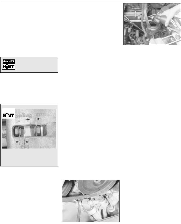
1•12 Every 9000 miles or 12 months
14 Brake fluid renewal |
3 |
|
17 Power steering fluid check 2 |
Warning: Brake hydraulic fluid can harm your eyes and damage painted surfaces, so use extreme caution when
handling and pouring it. Do not use fluid that has been standing open for some time, as it absorbs moisture from the air. Excess moisture can cause a dangerous loss of braking effectiveness.
Old hydraulic fluid is usually darker in colour than new fluid.
Renew the brake and bleed the system. Refer to Chapter 9 for full details.
|
15 Brake pad check |
2 |
|||
|
|
|
|||
|
|
|
|
|
|
|
|
|
|
|
|
|
|
|
|
|
|
|
|
|
|
|
|
|
|
|
|
|
|
|
|
|
|
|
|
|
|
|
|
|
|
For a quick check, the thickness of the friction material on each brake pad can be measured through the aperture in the caliper body.
With the front or rear (as applicable) of the vehicle raised, remove the wheels and check brake pads for wear. Renew the pads if the lining is below that specified. See Chapter 9, for specifications and full details.
16 Handbrake linkage check |
2 |
|
|
With the vehicle raised, check the operation of the handbrake and lubricate the linkages. Refer to Chapter 9, for further details.
1With the engine off, remove the cap from the power steering reservoir. It is fitted with a dipstick.
2The fluid should be visible up to the ‘MAX’ mark (1), (see illustration). If not, top it up using specified fluid.
3Start the engine and immediately top-up the fluid to the ‘MIN’ mark (2).
4Do not allow the reservoir to run dry.
5For details on how to bleed the system, refer to Chapter 10.
18 Power steering pump |
2 |
drivebelt check |
|
|
|
Note: Vauxhall specify the use of a special gauge. Checking values for use with this gauge are given in the Specifications in Chapter 10, for reference.
Checking
1 The correct belt tension can be approximated by adjusting the length of the threaded rod. This should give a belt deflection of approximately 10.0 mm (0.4 in) under moderate thumb pressure at the midpoint of the belt run between the pulleys. If in doubt, err on the slack side, as an excessively tight belt may cause pump damage.
2 Check the condition of the belt and renew it if there are any signs of damage or excessive wear
Adjustment
3Slacken the adjuster and mounting bolts.
4Slacken the adjuster nuts, and adjust the length of the threaded rod to remove or tension the belt as desired (see illustration).
5Tighten the adjuster nuts, and tighten the adjuster and mounting bolts to the specified torque (see Chapter 10), on completion.
6If a new drivebelt has been fitted, recheck the tension after a few hundred miles.
18.4Adjusting the length of the power steering pump threaded rod
17.2 Topping-up the power steering fluid level
19 |
Rear suspension level |
2 |
|
control system check |
|
|
|
|
Refer to Chapter 10, for details. |
|
|
|
|
|
20 |
Bodywork check |
1 |
|
||
|
|
|
1Clean the outside of the vehicle. If possible, clean underneath as well. If using a pressure cleaner take care not to damage any electrical components, especially in the engine compartment.
2Check all around for signs of damage or corrosion and treat accordingly. Repair stone chips when you can to prevent rusting.
3Read Chapter 11, for more details.
21 Lock and hinge check |
2 |
|
|
|
|
1 Lubricate locks and hinges on all doors, tailgates (or boot lid) and bonnet.
2 Check for wear or damage and ensure correct operation of safety catches.
3Check security of the bonnet stay and it’s securing clip.
4Read Chapter 11, for further details.
22 Alternator V-belt check |
2 |
|
|
Note: The new ribbed V-belt, fitted to later models, can not be adjusted.
1 Although special tools are available for measuring the belt tension, a good approximation can be achieved. Tension the belt so that there is approximately 13.0 mm (0.5 in) of free movement under firm thumb pressure at the mid-point of the longest run between pulleys.
2 With the mounting bolts just holding the unit, lever the alternator away from the engine using a wooden lever at the mounting bracket end until the correct tension is achieved. Then
 Loading...