

Page 1

VAUXHALL Vectra
Owner’s Manual
Page 2

Data specific to your vehicle
Please en t er yo u r veh icle ’s dat a he re to ke ep it ea sily acces sib le.
This information is available under the section "Technical da ta" as we ll as on the identification plate.
Fuel
Designation
Engine oil
Grade
Viscosity
Tyre inflation pr essure
Ty re si ze wi th up to 3 persons wi th full lo ad
Sum mer tyres Front R ear Front R ear
Winter tyres Front R ear Front
Weights
Permissible gross vehicle weight
– EC kerbweight
=Loading
Level control
Bumper Height
0
see page 1 79
R ea r
Page 3

Your Ve ctra
Develope d to the la test findings of vehic le research, it offers technical s oph istication and exceptiona l comfort.
Your vehicle represents an ideal synthesis of ad vanced technology, outstanding safety, environmental compatibility and e conomy in
operation.
It now lie s with you to drive your vehicle safely and to s ee it pe rforms pe rfectly.
This Owner's Manual provides you with all the necessary information to that end.
Th e Owner's M anual s h ould a lways be ke pt i n the v ehicle: ready to h and i n the g love co m part ment.
Make u se of the Owner's Manual :
z Its “I n brief” section will giv e you an initial overview.
z Its inde x will help you find what y ou want.
z It will familiarize you with the sophisticated technology.
z It will increase your pleasure in y our vehicle.
z It will help you to handle your vehicle ex pertly.
The Owner's Manual is de signed to be clearly laid-out and easily understood.
This symbol:
6 signifies: continue re ading on next page.
3 The asterisk sig nifies equipment options not in all ve hicles (model variants, engine options, models specific to one country, optional
equipment, Genuine Vauxhall Parts and Accessories).
Text highlighted in yellow in p articular indica tes possible risk of accident and
injury. Disregard of these notes can lead to injuries which may b e fatal. Vehicle
passengers must b e informed accordingly.
Yellow arrows in the illustrations serve as points of reference or indicate some action to be performe d.
Black arrows in the illustrations indicate a reaction or a second ac tion to be performed.
We wish you many hours of pleasurable driving
Your Vauxhall team
1
Page 4

2
Page 5

Contents
Commitment to customer
satisfaction:
Our ai m: to k eep you happy with your
vehicle. All Vauxhall Authorised Repairers
offe r first clas s service at competitive
prices. Experienced, factory-train ed
technicians work according to factory
instructions.Your Authorised Repairer can
supply you with GEN UINE VAUXHAL L-
APPRO VED PARTS , which have undergone
stringent quality and precision chec ks, and
of course useful and attractive
VAUXHALL-APPROVED ACCESSORIES.
Our name is your guarantee!
For d eta ils of the
Vauxhall Au thorised Rep aire r Netw ork
please ring this number; 01582 - 427200
In b rie f .. ......... ......... ......... ......... ......... ........ . 4
Instrument s ... ..... .... .... ..... .... ..... .... ..... .... .. 33
K eys, doors, b onnet .. ......... ..... ......... .... .. 54
S eats, Interior ..... ........ ..... ......... .... ......... .. 69
S afety s ys tems .. .... ......... ......... ......... ...... 94
Ligh ting ..... .... ..... .... .... ..... .... ..... .... ..... .... 116
Win do ws, sun ro of . .... ..... ......... ......... .... 12 0
C lim ate c ontro l .. .... ......... ......... ......... .... 12 6
Au tomatic t ransm ission . .... ......... ......... 144
C VTr onic ... .... ..... .... .... ..... .... ..... .... ..... .... 150
Driving hin ts .. ..... .... ......... ......... ......... .... 15 8
S ave fue l, pro tec t the e nv ironme nt .... 160
Fuel consum ption, fuel, re fu e lling ....... 162
C atalytic co n ve r ter, e xh au st gases .... 16 4
Drive control sys tem s ..... .... ......... ......... 168
Brake s ... ......... ......... ......... ......... ......... .... 18 0
Wheels, tyres . ..... ........ ......... ......... ......... 184
Roof racks,
caravan and tra iler towin g . ......... .... 188
S elf-h elp .... .... ......... .... ......... ..... ......... .... 199
If y ou have a pro blem ........ ..... ......... .... 23 2
Mainte nance , In s pec tion s ys tem .... .... 23 4
Vehicle care .. ..... ........ ..... ......... .... ......... 245
Te chnical data ...... .... ......... ..... ......... .... 250
Inde x . ......... ......... ........ ......... ......... ......... 282
3
Page 6
In brief
Key numbers,
Code numbers
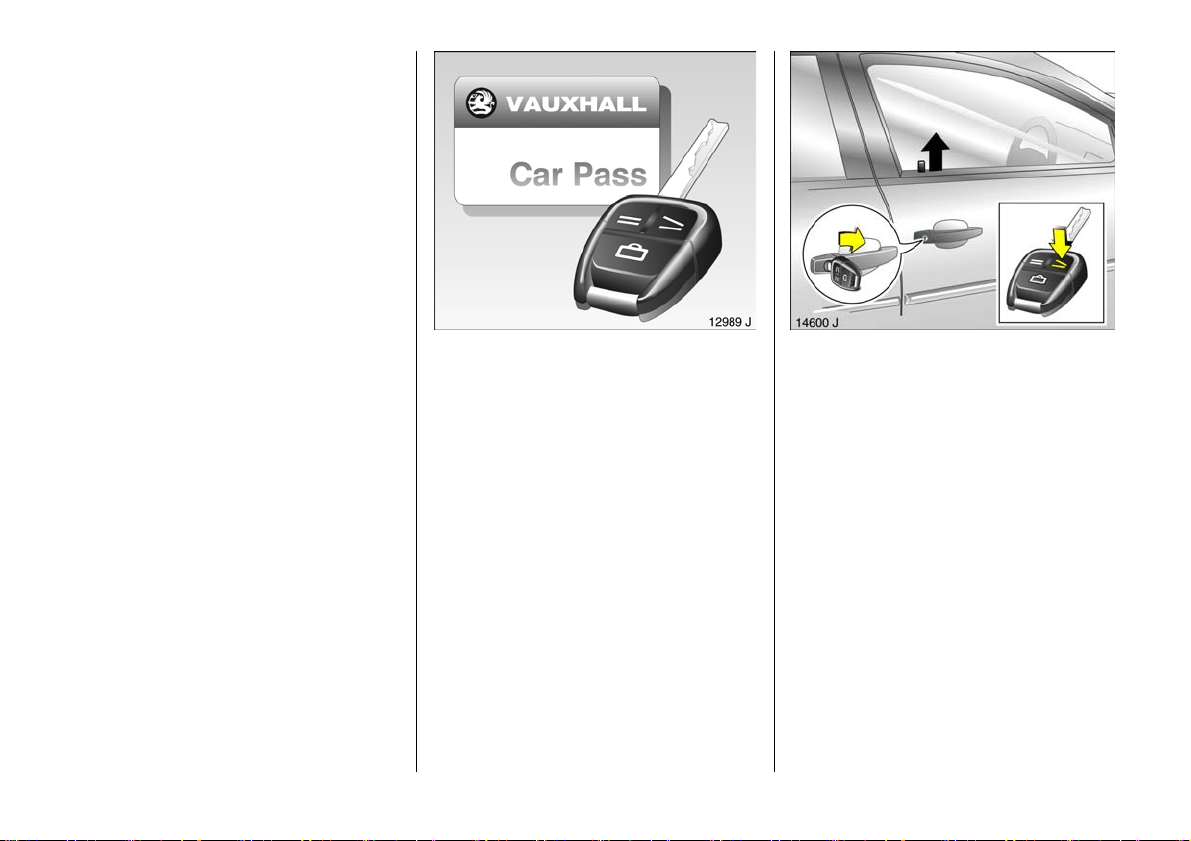
Remove key number from ke ys.
The key number is specified in the vehicle
documents and in the Car Pass 3.
Alloy whe els 3, towing equipment 3: make
a note of the key identifier codes.
Elec tronic imm obiliser, Radio 3 : the cod e
numb ers are specified in the Car Pass and
Radio Pass 3 respectively.
Do not keep the Car Pass and Ra dio Pass in
the vehicle.
6 Further information – se e pages 54, 55,
vehicle recomm issioning – see page 244.
4
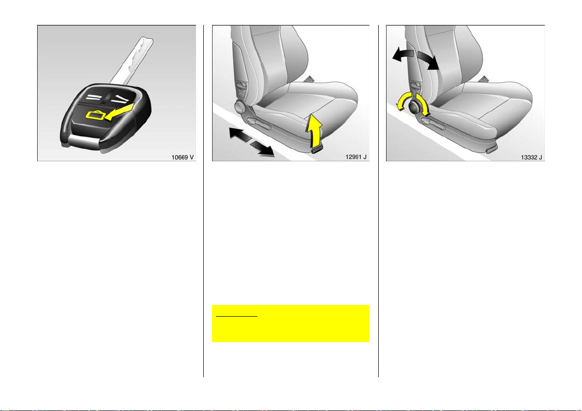
Unlock vehicle:
Press button q or
tur n ke y in dr iv er ’s side do o r loc k ,
pu ll d oo r h andle
Once = Driver’s door is unlocked.
Twice = Entire vehicle is unlocked.
The luggage
compartment is
automatically relocked
after 5 minutes.
6 Door lock s, child sa fety lock –
see page 54,
electronic immobiliser – see page 55,
radio frequency remote control –
see page 5 6,
central locking system – see page 58 ,
anti-theft locking system 3 – see p age 58,
Vauxhall alarm system 3 – see page 63.
Page 7
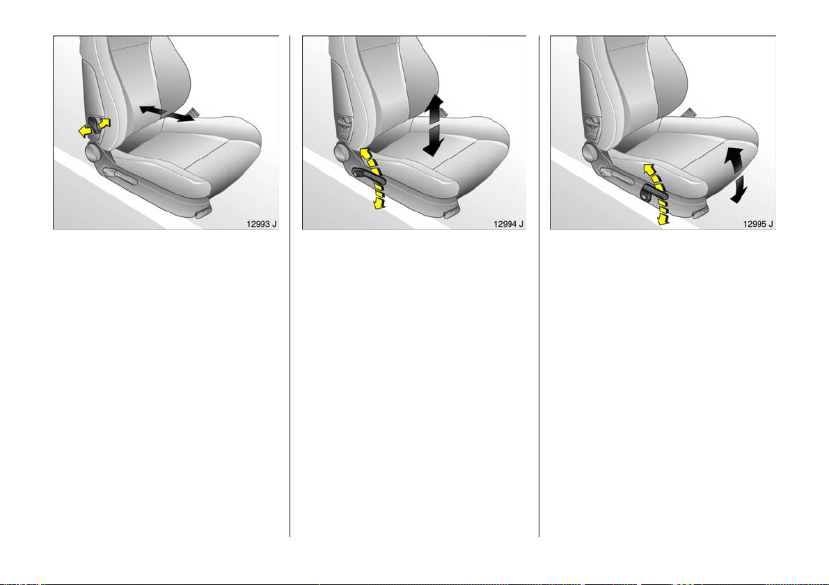
Unlock luggage compartment:
Press button r o n rem ote c ont rol o r
button
x in the dri v er or
passenger door
The luggage compartme nt is unlocked and
can be opened within 5 minutes.
If the luggage compartme nt is not opened
within 5 m inutes, it is automatically locked
again.
The lugga ge c om partment is automatically
locked 5 minutes after closing.
6 Radio frequency remote control –
see page 5 6,
central lock ing – see page 5 8,
Vauxhall alarm system 3 – see page 63.
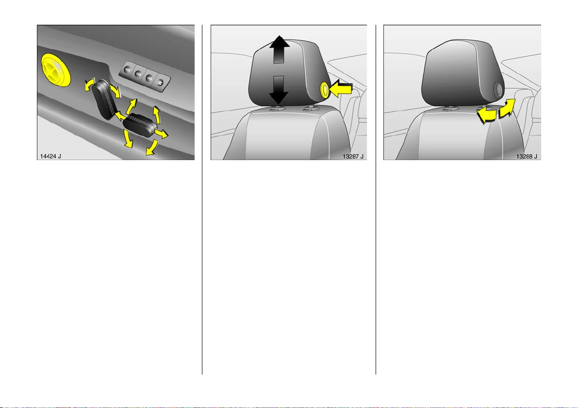
Front se at adjustmen t:
Pull handl e,
slide seat ,
rel ea se handl e,
al lo w se at t o a udib l y lat ch
into position
Never adjust the seat while driving. It could
move in an uncontrolled manner when the
ha ndle is pulled.
6 Seat position – see page 6 9,
electrically adjustable front seats –
see page 79.
Im porta nt : Do not sit nearer than 10
in ch es (2 5c m) f ro m t he s t ee ring wh ee l, t o
permit safe airbag dep loy men t.
Adjust fr ont seat backr ests:
Turn h andwh eel
Move seat bac krest to suit sea ting position.
Do not lea n on seat back rest whilst
adjusting it.
6 Seat position – see p age 69,
electrically adjustable front seats –
see page 7 9.
5
Page 8
Adjusting front seat lumbar support:
Adjust lever
Adjust lumb ar su pport to suit pe rsonal
requirements.
Do not lean on sea t backre st whilst
adjusting it.
6 Seat position – see page 69,
electrically a djustable front sea ts –
see page 7 9.
6
Adjusting front seat h eight 3:
Operate l ever on outboard side
of seat
Pu m p direc t i on of t h e le v e r
Up: R a i se s se at
Down: Lowers seat
6 Seat position – see page 6 9,
electrically adjustable front seats –
see page 79.
Adju sting fro nt s eat in cl inatio n 3:
Op e rate fron t lever on outb o ard si de
of seat
Pump direction of the lever
Up: Inclines seat
Do w n : Lev el s se a t
6 Seat position – see p age 69,
electrically adjustable front seats –
see page 7 9.
Page 9
Electric seat adjustment 3 :
Switch on outboard side of seat
Front:
– Longitudinal adjustment,
– Height adjustment,
– Angle adjustm ent.
Middle:
– Backrest adjus tment.
Rear 3:
– Lumbar support.
6 Seat position – see page 69,
electrically a djustable front sea ts –
see page 7 9.
Adjusting head restraint height of
front and rear outboard seats:
Press bu tton to release
and a d ju st he ight ,
engage in position
6 Head restraint position – se e page 70,
rear he ad restraints – s ee page 70.
Adjusting head restraint angle of
front and rear outboard seats 3:
Swivel bottom edge of head restraint
forward or rearward
6 Head restraint position – see page 70,
rear head restraints – se e p age 70.
7
Page 10
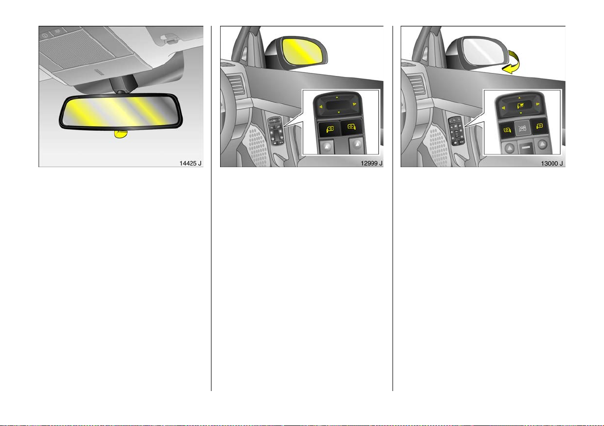
Adjusting interior mirror:
Swivel mirr or hous ing
Swivel lever on underside of mirror housing
to red uce daz zle a t night.
Automatic anti-dazzle interior mirror 3:
Dazzle at night is automa tically reduced –
see page 114.
6 Pos i t i on m emo ry 3 – see page 80.
8
Adjusting ext er ior m irrors:
Four-way switch on driver’s door
Press switch for left or right hand mirror:
four-way switch operates the
co rr e sp on d in g m i rr or .
Vehicles with electric seat adjustment 3:
if the mirror switch for the passenger side is
depressed when re verse gear is e ngaged,
the passenger side exterior mirror
repositions itself towards the rear tyres in
order to serve as mirror parking assistance
(no t wh e n tow ing a carav an / tr aile r).
Automatic anti-dazzle exterior mirror on
the driver’s side 3: dazzle at night is
automatic ally reduced – see page 1 14.
6 Further information, aspherical exterior
mirror 3 – see pa ge 114,
heated exterior mirrors – see page 20,
electric se at adjustment 3 – see page 79.
Swin g in exterio r mir ro r:
Manually: press lightly.
Electric 3 (both mirror switches must n ot b e
latched into position):
Push four-way switch to the right: exterior
mirrors swivel in.
Push four-way switch to the left: e xterior
mirrors swivel out.
The mirrors can a lso be s wivelled in from
the outside: press button p on remote
control or turn key toward rear of v ehicle in
driver’s door lock and hold.
Swivelling only a llowed at spe eds of up to
4 mph (7 km /h).
Page 11
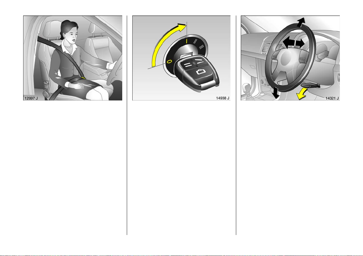
Fi ttin g sea t belt :
Draw se at belt smoothly
from inert ia ree l,
guide o ver shoulder
and engage in buckle
The belt must not be twisted at any point.
The lap be lt must lie snugly against the
body. The backrest must not be tilted back
too far (recomm ende d tilting angle
approx. 25°).
To release belt, press re d button on belt
buckle.
6 Seat belts – see pa ges 9 5 to 99,
ai r bag sy st e ms 3 – see page 100,
seat p osition – see page 69.
Disen gagin g st eer ing c olumn lo ck:
To re lease the loc k ,
move the s teering wh eel sl ightly
and turn the key to position I
Positions:
0 =Ignition off
I = Steering free, ignition off
II =Ignition on,
with dies el e n g ine: pr e-heat
III =Start
6 Starting – se e page 23,
electronic immobiliser – see pag e 55 ,
re mo ve ke y a nd l oc k s te e rin g w he el –
see page 24.
Steering whee l adjustment 3:
Move lever down,
adjust height and distance,
move lever up,
engage
Adjust steering wheel only when vehicle is
stationary and steering colum n lock is
released.
6 Airbag systems 3 – see page 100.
9
Page 12
10
Page 13

Page
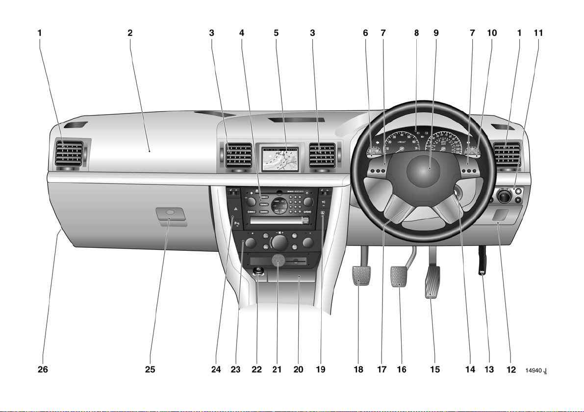
1 Side air v ents ... ..... ......... ........ ......... 129
2 Front pa ssenge r air bag ........ ........ 100
3 Centre air v en ts .... .... ......... ......... ... 12 9
4 Radio 3
or Infotainment system 3 . ......... ..... 5 2
5 Central information dis play for
date, time, outside temperature,
Infotainment system 3,
radio 3,
check control 3,
trip computer 3,
electronic air conditioning
system 3 . ..... .... ..... .... ..... .... .... ..... .... . 41
6 Turn signals, headlight fla sh,
dippe d an d main be am ... .... ..... 16 , 1 7
Door-to-door lighting 3 and
parkin g lights .. ......... ......... ......... ..... 17
Cruise control 3 .... .... ..... .... .... ..... .... 172
7 Remote control 3 for radio a nd
Infotainm en t system ..... ........ ......... ..3 0
8 Ins tru me nts ...... ..... ......... .... ......... .... ..33
9 Horn .... ......... .... ......... ..... ........ ..... ...... 1 8
Pa ge
10 Windscreen wiper and wash system,
headlight wash system 3 and
rear window wash system 3 .. ..... .... 19
Display operation 3 . ..... ..... ..... ..... .... 48
11 Exterior lighting ... ......... .... ......... ..... 116
Instrument illumination ........ ......... 1 1 7
Fog tail lig ht ........ ..... ........ ......... ..... 116
Front fog ligh ts 3 ..... ........ ......... ..... 11 6
Headlight range adjus tment 3 ..... 11 7
12 Stowage compartment
13 Bonne t release lev er ........ ..... ......... . 68
14 Ignition lock
wit h ste ering whe el lock .. ......... ........ 9
15 Accele ra tor pedal .... .... .... ..... .... .... 158
16 Brake peda l ..... ......... ........ ..... 15 9 , 1 8 0
17 Stee r ing whee l po siti o n adjus ter .. ... 9
18 Clutch ped al 3 ......... .... ......... ........ 1 5 9
Page
19 Heated seat (right) 3 . ..... ......... ..... 130
Anti-theft alarm system 3 .. ..... ...... 6 3
Rear window blind 3 ....... ......... .... 125
Traction Control system 3 .. ..... .... 168
Electronic Stability Program me 3 17 0
20 As htray s ......... .... ..... .... ..... .... ..... .... .. 90
21 Telematics 3 .. ......... .... ......... ..... ...... 52
22 Cigarette lighte r 3 ...... ..... .... ..... .... ... 8 9
23 He ating, ventilation,
air conditioning system 3 ........ .... 126
Electron ic air con ditioning
system 3 ..... .... ......... ......... ......... .... 126
Auxiliary heating 3 ......... .... ..... .... 140
24 Heated seat (left) 3 and
seat climate control .... ......... ..... .... 13 0
Haz ard warnin g light s ........ ......... .. 18
Parking dis tance sensors 3 . ..... .... 174
25 Glove compartment
26 Fusebox . ..... .... .... ..... .... ..... .... ..... .... . 212
11
11
Page 14

Control indicators
O Turn signal lights:
see pages 17, 33.
I Oil p ress ure:
see page 33.
R Brake system,
clutch system:
see pages 34, 181.
p Alternator:
see page 34.
v Airbag systems,
bel t tensioners:
see pages 96, 105.
W Coolant t em perature:
see pages 34, 40.
X Seat belt 3:
see page 35.
T Automatic transmission 3,
CVT ronic 3,
winter program me :
see page s 147, 155.
! Glow plugs 3:
see page 3 5.
u Anti-lock Brake System :
see page 1 83.
v Traction Control system 3,
Electronic St abili ty Progr amme 3 :
see page s 168, 170.
> Front fog li ghts 3:
see page s 35, 116.
r Fog tai l light:
see page s 35, 116.
P Main beam:
see page s 16, 35.
y Seat occup ancy recognition 3:
see page 105.
m Cruise control 3:
see page 172.
Y Fue l le vel:
see pages 3 6, 40, 199.
Z Exhaust emission 3:
see pages 3 6, 166.
B Adaptive Forward Lig hting
(A FL ) 3:
see pages 2 8, 118.
g Trailer turn signa l 3:
see page 36.
12
Page 15

Disp la y in ta c ho meter
The following control indicators will
illuminate as ne cessary:
o Imm obiliser:
see pages 37, 55, 166.
p Ele ctro -hy drau lic
power assisted steering:
see page 37.
q Headlight range adjustment 3:
se e p age 11 7.
r Parking distance sensors 3:
se e p age 17 4.
A Engine electronics,
transmission elec tronics 3:
see pages 37, 55, 166.
s Open lugga ge compa rtment:
see pages 37, 61.
v Airbag systems,
bel t tensioners:
see pages 96, 105.
t Bulb replacement 3:
see pages 38, 218.
F Brake pad w ea r indicator 3:
see page s 38, 180.
S Engine oil level:
see page s 38, 236.
H Cool ant fluid level:
see page s 38, 239.
v Serv ice inte rval display :
see page 2 34.
x Tyre pressure control system 3,
loss of pressure w arning from the
respectiv e tyre:
see page s 38, 176.
w Tyre pressure control system 3,
fault:
see page s 38, 176.
y Doors open 3,
indi cating the respe cti ve door:
see page 3 8.
Lighting
Light switch, stalk positi ons:
see page s 16, 116,
7 Lights off
8 P ark ing lig hts
9 Dipp ed and main beam
> Front fog lights 3:
see page 116.
r Fog tail l igh t:
see page 116.
P Main beam :
see page 16.
O Turn signal lig h ts:
see page 17.
k Instru me nt il luminati on:
see page 117.
? Hea dlight range adjustment 3:
see page 117.
b Courtesy li ght:
see page 118.
c Courtesy li ght deact ivat ion 3:
see page 118.
a Reading lights, front 3 :
see page 118.
¨ Haz ard w arning lig hts:
see page 18.
13
Page 16

Climate control
x Air flow:
se e p age 12 7.
Air distri bution:
se e p age 12 7,
L to he ad are a ab ove ad justable
air vents and to footwell,
M to head are a ab ov e
adjustable air ve nts
front and re ar 3,
l to w i nd sc r e e n ,
J to w i nd sc r e e n an d
to footwell,
K to footwell.
V Demi st ing and d efrosti ng 3:
see pages 133, 137.
Ü Heated rear window:
se e p age 12 8.
n Air conditioning system 3:
see page 1 28.
4 Air recirculati on system 3:
see page 1 28.
AUT OAutom atic mode 3:
see page 1 35.
ß He ated seats 3:
see page 1 30.
A Driv er’ s se at with clim ate con trol 3:
see page 1 30.
b Re mote cont rol of aux iliary
he ating / v ent ilation 3:
see page 1 40.
Sun roof 3
d Sun roof:
closing – see page 123 .
ü Sun roof:
opening – see p age 123.
f Sun roof:
comfort setting – see page 1 23.
e Sun roof:
raising – see page 123.
Windscreen wiper
Stalk positions:
see page 19,
§ Off,
$ T ime d interv al wi pe, or automa tic
wipe w ith rain se nsor 3,
% Slo w,
& Fa st.
14
Page 17

Date, time, information display, radio
Informat ion displa y:
see page 41.
Ö On button for date and time,
; Setting buttons for date and tim e.
Buttons on wiper stalk 3:
see page 42.
i Tri p c omp u te r ,
forwards me nu search,
h Tri p c omp u te r ,
backwards me nu search ,
§ Trip computer, se lect
Remote control 3 for radio
and Infotainment system:
see page 30.
Cruise control 3
But tons on turn signal sta lk:
se e p age 17 2.
m On, Accelerate ,
g De ce ler at e,
§ Off.
Miscellaneous
p Ce ntra l locking s ystem:
locking – see page 58.
q Ce ntra l locking s ystem:
unloc king – see page 58.
r Bo ot li d / tail gate:
unloc king – see page 61.
x Luggag e compart me nt:
unloc king – see page 61.
m Centra l lock ing switc h:
see page 5 9.
Ä Anti- theft alarm system 3 :
see page 6 3.
z Chi ld safe ty sw itch 3 :
see page 1 21.
N Rear w indow b lind 3:
see page 1 25.
r Parking distance sensors 3:
see page 1 74.
) Ciga ret te lighter 3:
see page 89.
j Horn:
see page 18.
/ Bonnet:
see page 68.
T Wi n ter pro gram me,
automa tic transm ission 3,
CVT ronic 3:
see pages 147, 155 .
j Se lector leve r lock ing,
automa tic transm ission 3,
CVT ronic 3:
see pages 144, 151 .
+ Fir st - aid k it 3:
see page 204.
¨ Wa rning tri angle 3:
see page 204.
15
Page 18
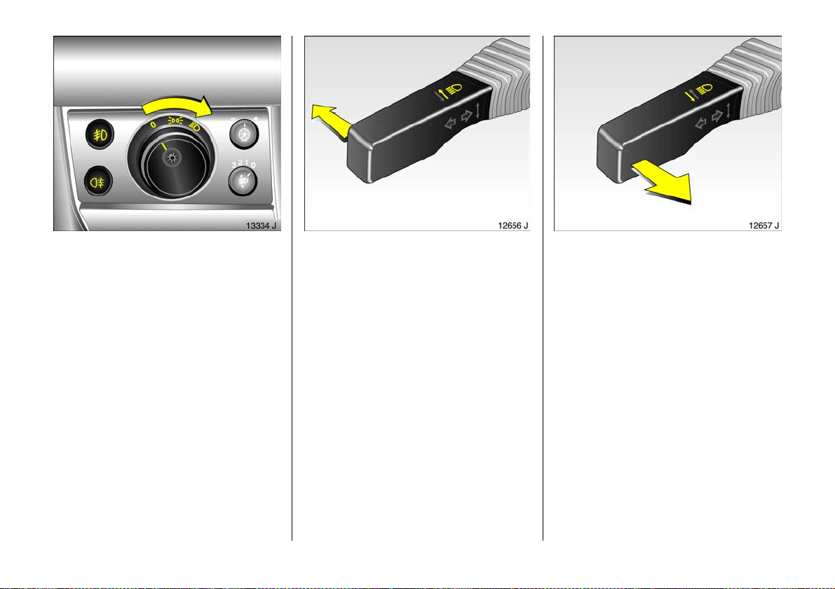
Light switch:
7 =Off
8 = Parking lights
9 = Dipped or main beam
Press r = Fog tail light
Press > = Front fog lights 3
6 Other notes – see page 116,
headlig ht warning device – see page 24,
headlig ht ra nge adjustment 3 –
see page 117,
instrument illumination 3 – see page 117,
daytim e d riving lights 3 – see page 116.
16
Main and dipped beam switch:
Main beam = Push stalk forward
Dipped beam = Push stalk forward
again
You can also switch from main beam to
dipped bea m by pulling the stalk towards
the steering wheel.
Headlight flash:
Pull stalk to wards steering wh eel
Page 19
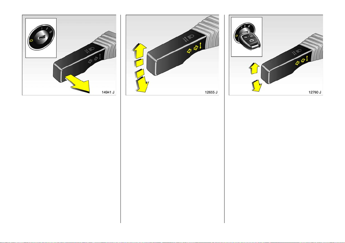
Operating door-to-door
light ing1) 3:
Key to position 0 and remove,
open driver’s door,
pull turn signal stalk towards
steer ing wheel
Dipped beam and the reversing lights light
up for an add itional 30 seconds after the
driver’s door is closed.
If the driv er’s do or is left o pen, th e ligh ts will
go out after tw o minutes.
Door-to-door lighting can be deactivated
by inserting the key in the ignition switch or
by pulling the turn signal stalk towards the
steering wheel aga in while the driver’s door
is open.
1)
"D oor-to-door" light func tion.
Operating turn signal lights:
Right = Stalk all the way up
Left = Stalk all the way down
The turn signal stalk retu rns to its original
position after use. When the steering wheel
is straighte ned up, the turn sign al lights are
automatic ally cancelled.
Switch the turn signal off manually by
tapping the stalk.
When changing lanes , tap stalk until
resistance is felt: the resp ective turn signal
will flash three times.
Hold the stalk if you want the turn signals
to flash longer.
Operating parking lights:
Light swi tch to position 0,
ignition key to position 0,
move turn signal stalk fully
upwards or downwards
As a check, a warning buzzer sounds and
the turn signal control indica tor on the
respective side illuminates.
To switch it off, switch on the ignition or
mov e the turn signal stalk in the opposite
direction.
17
Page 20
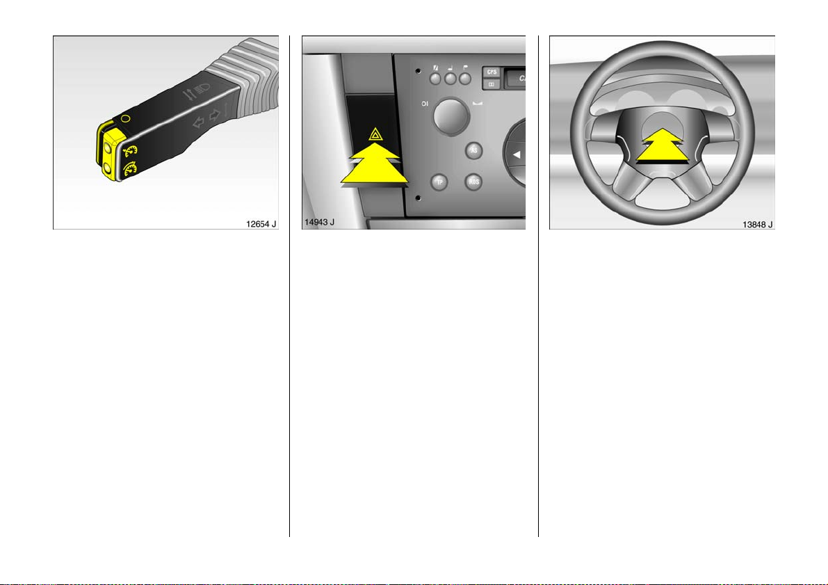
Cruise control operation:
Press button on stalk
Switch on: tap button m.
Switch off: tap button §.
Resume at stored spe ed: tap button g.
6 Cruise control 3 – see pa ge 17 2.
18
Hazar d w a rn ing ligh ts :
On = Press ¨
Off = Press ¨ again
To aid location of the pushbutton, the red
surface is illuminated when the ignition is
switched on. When the button is pressed,
its control indicator flashes in time with the
ha zard warning lights.
Sounding the horn:
Press the centre of the steering w hee l
6 Airbag systems 3 – page 100,
remote control for radio and
Infotainment system 3 – page 30.
Page 21
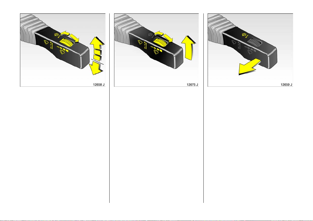
Windscreen wiper:
Gent ly tap stalk upward
§ = Off
$ = Adjustable timed interval wipe
% = Slow
& = Fast
Stalk always mov es back to starting
position. Shift to ne xt gear up or down: just
tap stalk g ently.
Push stalk pa st resistance point and hold:
windscreen wiper stages are selected .
Adjustable interva l wipe $:
Shorter inte rv als = Turn adjuster wheel to
right
Longer intervals = Turn adjuster wheel to
left
Press the stalk down from position §:
Single sw ipe.
6 Further in form ation – see pages 240,
241, 246.
Automatic wiping with rain sensor 3 :
Ge ntly t ap sta lk u pw a rd
§ = Off
$ = A uto ma ti c w ipi ng
w ith r a in senso r
% = Slow (constant)
& = Fast (constant)
Automatic wiping $: T he rain sensor
detects the amount of water on the
windscreen and automa tically regulates
the windscreen wiper. The sensitivity of the
system can be adjusted using the adjuster
wheel:
Less sensitive = To the left
M o re s en s it iv e = T o th e ri g ht
If ne ce ss ary, t h e p o si t io n s % or & ca n b e
selected manually.
To switch of f , m ov e st a l k d ow nwa rd s.
6 Further information – se e pages 240,
241, 246.
Operating windscreen and
headlight wash syst ems 3:
Pull stalk to wards steering wh eel
The wiper w ill swipe for a fe w strokes. At
low speeds, there is a one-time post-wash
swipe.
The headlight wash system 3 is ready for
operation when the lights are switched on.
Wash fluid is sprayed onto the headlights
(twice). Subsequently the headlight wash
system is blocked for 2 minutes.
The headlight wash system is deactivated
if wash fluid is low.
On vehicles fitted with rain sensor 3, ke ep
the sensor area clean.
6 Furth er information – see page s 241,
242, 246.
19
Page 22
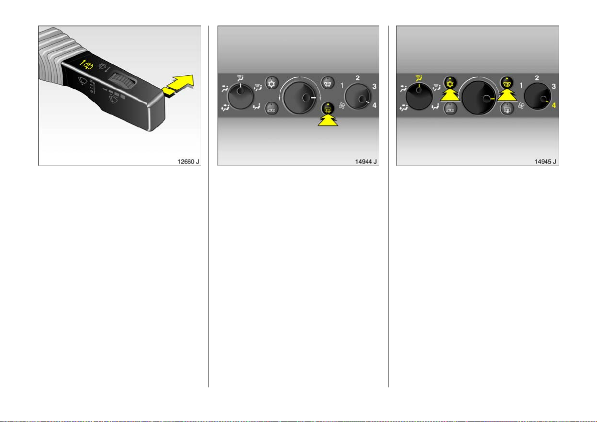
Rear window wiper 3 and
wash system 3
Operation:
Wiper on = Push st alk forward
Wiper o ff = Push sta lk for ward
again
Wash = Press and hold
The rear window wiper swipes in time d
interval mode.
W h en was h i ng , the w iper s wipe s for a fe w
strokes. At low speeds, there is a one-time
post-w ash swipe .
The rear window wa sh system is
deactivated if wash fluid is low.
6 Further in form ation – see pages 241,
242, 246.
20
He ated rea r win dow ,
heated ex terior mirrors:
On = Press
Ü
Off = Press Ü again
Heating operational only with engine
running.
The rear window and e xterior mirror
heating is switched off automatica lly after
approx. 15 minutes.
6 Further information – see p age 128.
Clearing misted o r icy windows:
Set air distribution to l,
tur n ro tary swit ches for
temper ature and f an c lockw ise
Air c on dit io ning sys tem
3:
Push V and n buttons,
tur n ro tary swit ch for
temper ature clockwise
Open front air vents, direct side air vents
towards the door windows. Close centre air
vents 3.
6 Heating, ventilation, air conditioning 3 –
see page 1 26,
electron ic air conditioning system 3 –
see page 134.
Page 23
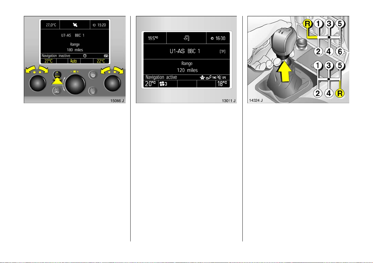
Set ti ng e lectr onic ai r c on dit io ning
system 3 to automatic mode:
Press A UTO bu tton,
set temperature for driver and
passenger sides us ing left and
right kn obs
Open all front air vents. If desired, the rear
vents also 3.
6 Electronic air c onditioning system 3 –
see page 1 34.
Info rma t io n di spla y:
Used to display information on:
–Time,
– outside temperature,
–radio 3 and date,
– navigation 3 ,
– telephone 3 ,
– chec k control 3,
–trip computer 3,
– electronic air conditioning 3.
6 Information disp lay 3 – see page 41.
Manual transmission
o =Neutral position
1 to 5 = 1s t to 5t h ge ar
6 = 6th gear
When shifting up from 4th to 5th gea r:
push the lever towards the right at the
beginning of the s hift operation.
Between 5th and 6th gear 3: push
gearshift lever to right in straight line.
When shifting from 5th to 4th gear:
do not e xert any force towa rd s the left.
3
R = Reverse gear
Reverse gear: w ith v ehicle stationary, pull
the ring up three seconds after de-clutching
and engage gear.
If the gear does not engage, set the lever in
neutral, release the clutch pedal and
depress again; then repeat gear selection.
21
Page 24
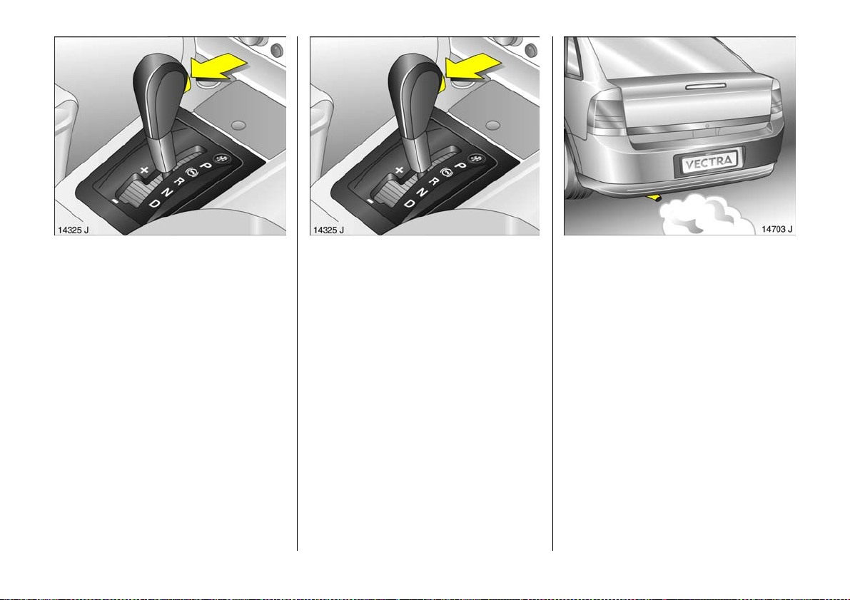
Automatic transmission 3:
P = Park position
R = Reverse gear
N = Neutral
D = Automatic gear selection
Sele ctor lev er in D t o left:
+ = Upshift
- = Downshift
Always start in P or N. To leave position,
opera te brak e pedal and press button on
selector lever (selector lever lock).
To e ngage P or R, push button on selector
lever.
P: Only with ve hicle stationary,
first apply handbrak e
R: O nly with vehicle stationary
6 Automatic transmission – se e p age 144.
22
CVTronic 3:
P = Park position
R = Rever se ge ar
N = Neutral
D = Co ntin uousl y va ri able
automatic mode
Selec tor leve r i n D to le ft:
Co ntin uo usly vari a ble
automatic mode
+ = Upshift
- = Downshift
Alw ay s sta r t in P or N. To le ave position,
op erate brake pedal an d pre ss button on
selector lever (selector lever lock).
To engage P or R, push button on selector
lever.
P: Only with vehicle stationary,
first apply handbrake
R: Only with ve hicle stationary
6 CVTronic – see pag e 15 0.
Exhaust gases are poisonous
Exhaust gases contain carbon monoxide,
which is extremely poisonous but is
odourless and colourless.
Therefore never inhale exhaust gases, and
never run the engine in an enclosed space.
Page 25
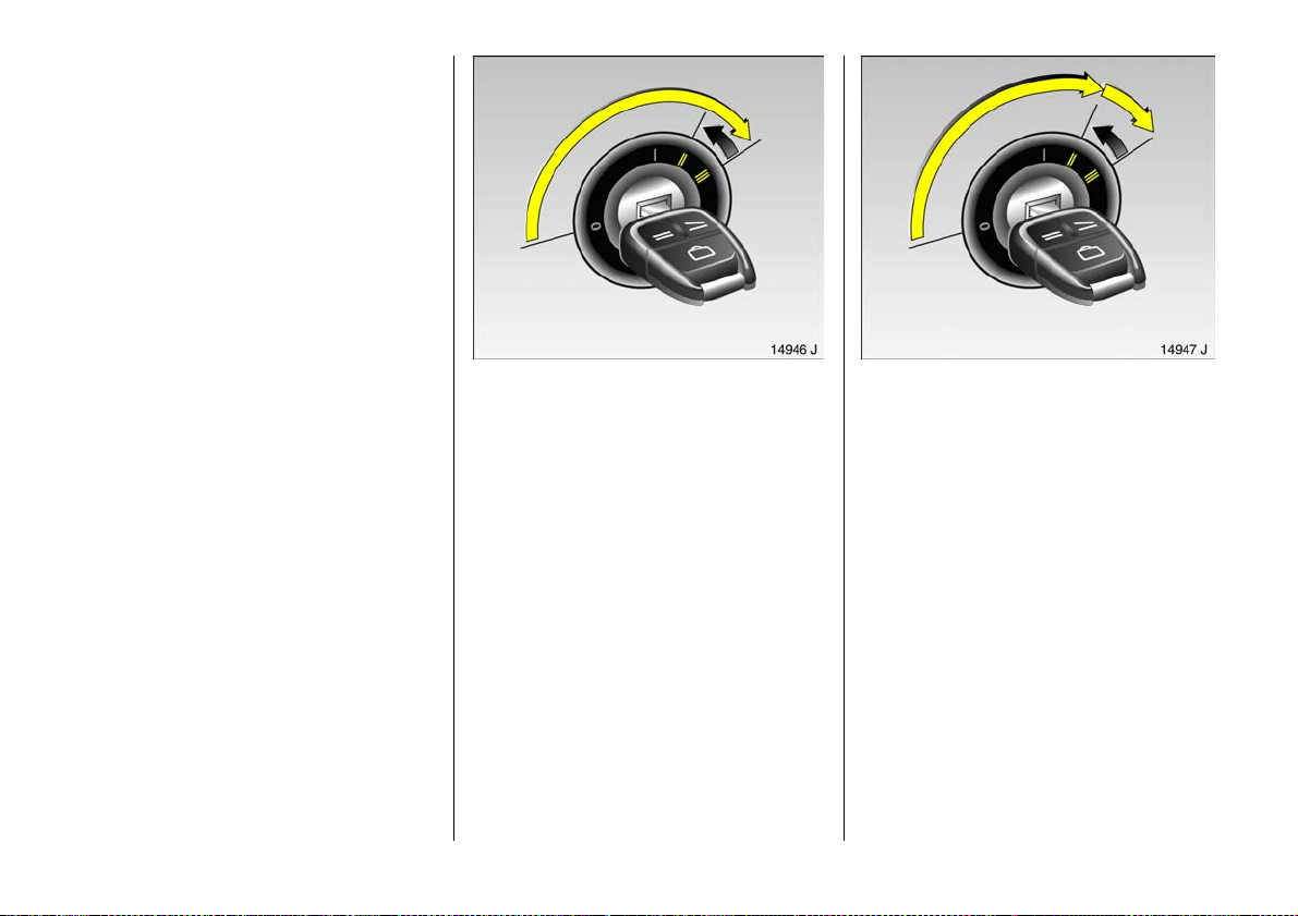
Before starting off, check:
z Ty re pressure and condition – see pag es
176, 184, 268.
z Engine oil level and fluid levels in engine
com partment – see pages 235 to 242.
z All windows, mirrors, e xterior lighting
and num ber p la tes ar e fre e from dirt ,
snow and ice and are ope rational.
z No objects are in front of the rear
wind ow, o n the in strume nt pan el or in
the area in which the airbags inflate.
z Seats, seat belts and mirrors are
corre ctly ad justed.
z Bra ke op er at ion.
Starting, petrol engines:
Manual transmission idling with
clutch pedal depressed,
operate foot brake,
automatic transmission or CVTronic
in P or N,
do n ot ac ce ler a te,
turn key to position III
The initially increased engine speed
automatically falls as the engine
temperature rises.
Before repea ting the starting proc edu re,
turn the key back to 0 in the ignition switch,
remove it and then reinsert it. Then repeat
the starting procedure.
6 Electronic immobilis er – see page 55,
further information – see pag es 158, 199.
Starting, diesel engine:
Manual transmi ssi on in neutral with
clutch pedal depressed,
apply foot brake,
au tom a tic tra nsmi ssi on in P or N ,
do not accelerate,
turn key to position II;
when control indicator
! goes out
1)
turn key to position III
Before repeating the starting procedure,
turn the key back to 0 in the ignition switch,
remove it and then reinsert it. The n repeat
the starting procedure.
6 Electronic im mobiliser – see pag e 55,
further information – s ee page s 158, 199.
,
1)
Preheatin g system switches on only if outside
tem perature is low.
23
Page 26
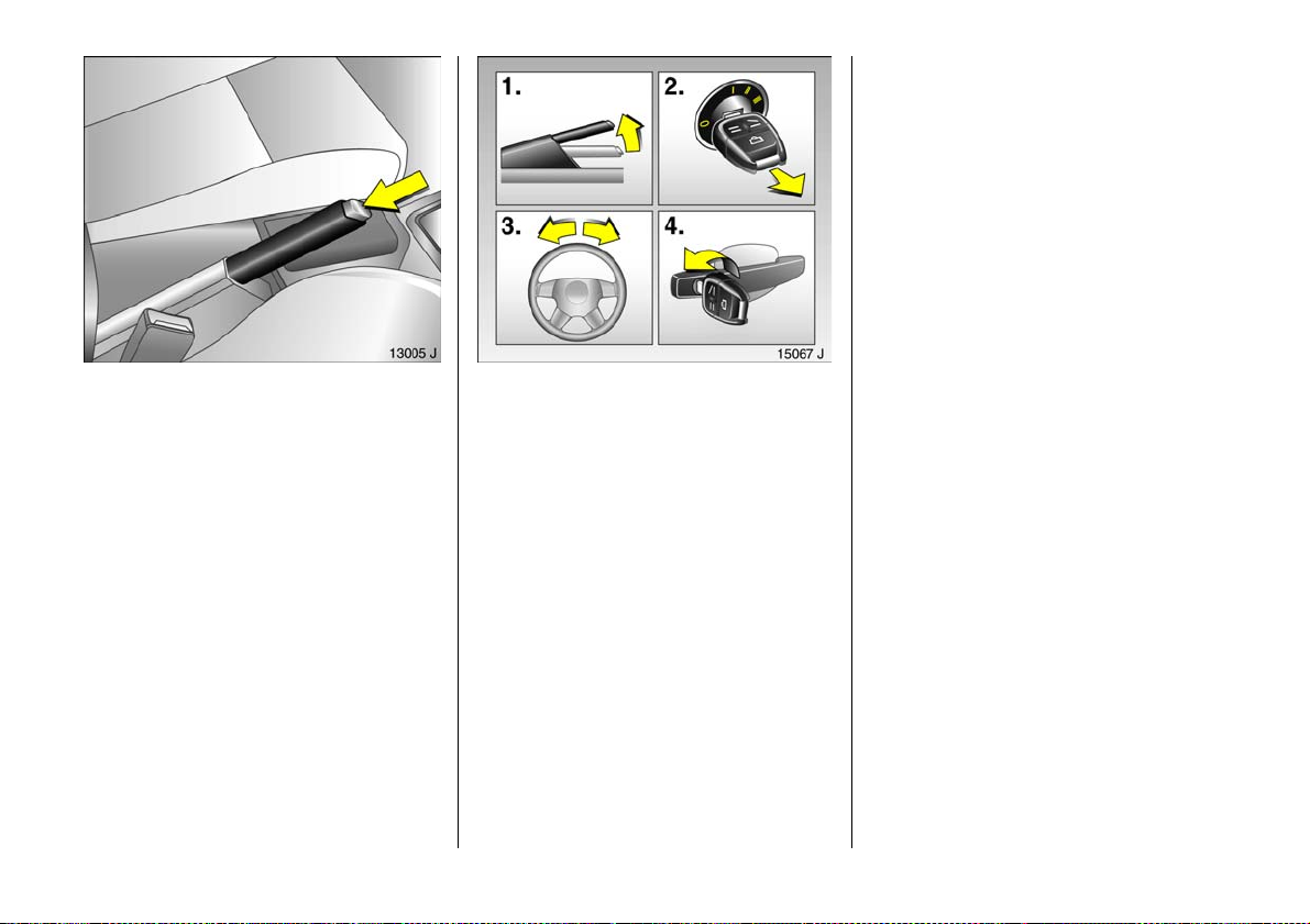
Rele as in g the h a ndbrake:
Raise leve r s lig h tly,
press lock button,
lower lever fully
6 Bra kes - see pag e 180
Parking t he vehicle:
Apply handbrake firmly,
engine off,
rem ove ke y,
lock s te ering wh eel,
lo ck ve hicl e
To lock, press button p or turn key
anticlockwise in the lock. To activate the
anti-theft lock ing system 3 and anti-theft
alarm system 3, press button p twice or
turn key anti-clockwise twice.
6 Further information – see pages 55, 158,
ra dio frequency remote control –
see page 56,
central locking s ystem – see page 58,
Vauxhall ala rm system 3 – s e e p ag e 63 ,
vehicle decommissioning – see page 244.
Advice when parking:
z Alw ays apply handbrake firm ly. On
slopes apply the ha nd brake as firmly as
possible.
z With m anual transmission, select first
gear or reverse, for automatic
transmission 3 or CVTronic 3, place
selector lever in P.
z Close windows and sun roof 3.
z In vehicles with autom atic transmission 3
or CVTronic 3 th e k ey c a n on ly b e
removed in selector lever p osition P.
z Turn steering wheel until y ou feel lock
engage (an ti-theft protection).
z Engine cooling fan may run on after the
engine has been s witch ed off.
Warn ing buzze rs
While driving:
z If seat belt is not fastened1),
z If a spe cified ma ximum speed is
ex cee ded1),
z If the luggag e com partment is ope n
wh en t h e vehicle starts off .
When the vehicle is parked and the driver’s
door is opened:
z If the key is inserted 3,
z If ex t erio r lights a re o n ,
z If the turn signal stalk is engage d.
24
1)
Count ry-speci fic ver sion.
Page 27
Servi ce wo rk , mainte nanc e
We recommend tha t you entrust all w ork to
a Vauxhall Authorised Repairer, who ca n
provide you with relia ble serv ice and
correctly perform all work according to
factory instructions.
6 If you have a problem– se e page 232,
service interval display – see pa ge 234.
Ge nu ine Vau xhal l P ar ts and
Accessories
We recommend "Genuine Vauxhall Parts
and Accessories" and conversion parts
released expressly for your vehicle type.
These parts have undergone special tests
to establish the ir reliability, safety and
specific suitability for Vauxhall v ehicles.
Despite continuous market monitoring, we
cannot assess or gu arantee these
attributes for other prod ucts, even if they
ha ve b een granted a pproval by the
relev ant authorities or in some other form.
"Genuine Vauxhall Parts and Accessories"
and conversion p arts app roved by
Vauxhall can be obta ined from a Vauxhall
Authorised Rep airer, of course. Here you
will be given comprehensive advice about
permitted technical changes and c orrect
installation will take pla ce.
For your safety
Carry out regularly the checks
recom mende d in the individual sections
of this Owner’s M anual.
Ensure that your vehicle is serviced at the
service intervals spec ified in th e Service
Booklet. We recommend that y ou entrust
this work to a Vauxhall Authorised
Repairer.
Have faults remedied without delay!
Consult a workshop. We recommend a
Vauxhall Authorised Repairer. If
necessary, interrupt your journey.
6 Maintenance – see page 234.
That was the mo st impo rtant
info rmatio n for y o ur f irst drive
inyour Vectra.
The other pages of this chapter
contain a sum mary of the other
interesting functions in your vehicle.
The remaining chapters of the
Owner’s Manual contain important
information on operation, safety and
maintenance as well as a complete
index.
25
Page 28

External window and sun roof 3
operation 3
Press button q or p on the remote control
until the windows are open or closed,
respectively.
Press button p on the remote control until
the sun roof is closed.
If the rain sensor 3 detects water with the
mechanical anti-theft locking system 3
activated, all electronic windows and the
sun roof are closed. The windows and the
sun roof are also automatic ally closed after
fo ur ho urs .
6 Further information – see pages 122, 124.
26
Position m emory 3 for electri cally
adj usta b le drive r’s seat,
exteri or mi rro rs and i ns ide rea r view
mirror
Storing setti ng s
1. Adjust seat and mirror,
2. Press m emory button M a nd the position
button to be used (1 , 2 or 3)
simulta neously. Storage is
acknowledged by an acoustic signal.
Retrieving settings
Press and hold down pos ition buttons 1, 2
or 3, until stored positions have been
re a ch e d .
Ad justme nts may only be performed with
vehicle stationary.
6 Further information – see p age 69.
Heated se ats 3,
driver’s s eat with climate control 3
O pera te the a djus ter wheels b e n ea th th e
centre air vents and buttons on the rear of
the centre console.
For the front seats, set knurled wheels to
require d ventilation setting 3 or heater
setting as per requirements. For rear
outboard seats, p ress buttons.
6 Furth er information – see page 130.
Page 29
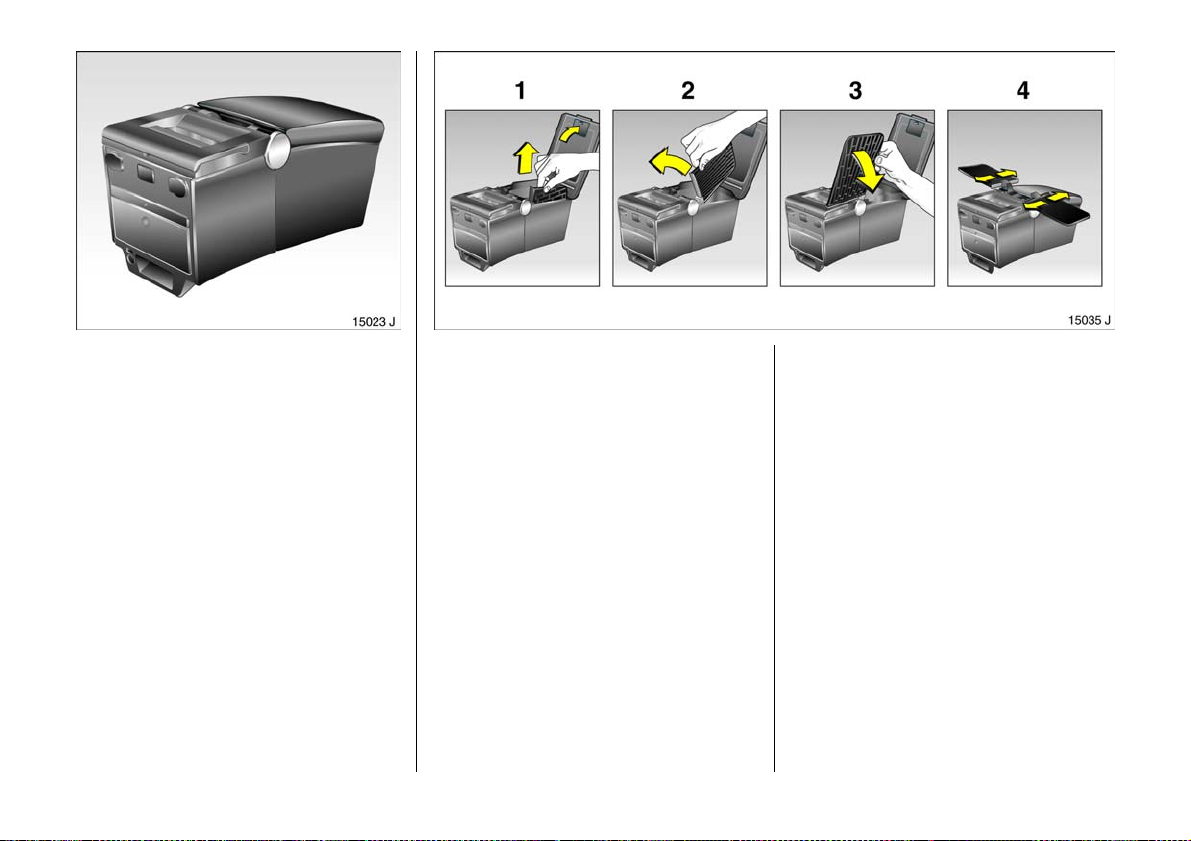
Travel Assistant 3
The Trav el Assistant con tains:
z armrest,
z stowage compartm ents,
z waste container,
z drink holders,
z accessory sockets,
z connection console
e.g. for DVD pla yer 3,
z elec tric co ol bo x,
z ta b l es ,
z tw in aud io (re ar audio module ) 3 or
stowage compartm ent.
The Trav el Assistant is installed on a
co n sole abo ve the m iddle se at i n the re ar.
Ta b le s
Fold arm res t u pwar d (1).
Use recessed grip to p ull tab le upward as
fa r as it will go (1 ), swivel table forw ard (2)
and fold downward (3 ).
Set required cleara nce by adjusting
longitudinal p osition of tab le (4).
6 Furth er information – see page 72.
27
Page 30
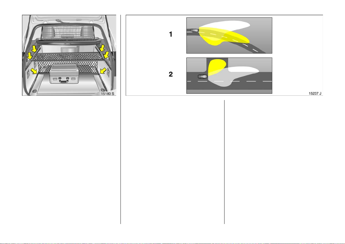
FlexOr ganizer 3
The side walls house a ttachment rails that
can be used as necessary for different
systems to divide the luggage
compartme nt or secure load s.
The system consists of:
z variable partition net
z variable partition wall
z partition rod
z mes h p o c ke t s f o r t h e si d e wal l s
z hooks
6 Further in form ation – see page 8 6.
28
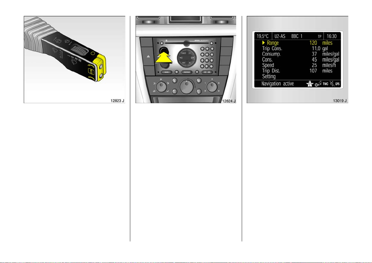
Ada pt ive F or war d L i gh t ing (AF L) 3
On vehicles with Bi-Xenon headlights,
improves illumination of
z curves (curve lighting),
z intersections and tight turns (turn
lighting).
C urve ligh ti ng
The Xenon light b eam pivots based on
stee ring whee l po sition an d s pe ed (f r o m
approx. 6 mph / 10 km/h).
The headlights shine at an angle of up to
15° to the right or left of the direction of
travel.
Turn lig hting
An additional light is switched on based on
stee ring whee l po sition (wh en t u rned past
app rox. 90 °), turn signal use and s peed (up
to app rox. 25 mph / 40 km/h).
The light shines at an a ngle from app rox.
90° to the left or right of the v ehicle up to a
distance of a pprox. 30 me tres.
6 Furth er information – see page 118.
Page 31
Operating the
graphi c al info rmatio n disp lay 3
or the colour information display
Using buttons on wiper stalk
Rear button:
§ Activate / confirm / select
Front buttons:
h Move up in the menu
i Move do wn in th e menu
3
Using multifunction button
Push Confirm / select
R o ta te M o ve in m en u
6 Further information – see p age 42.
Trip computer 3
Th e t rip co mpu t er shows vehicle d ata
which it continually records and evaluate s
electronically.
Functions:
z Range,
z Effective consumption,
z Average consumption,
z Instantaneous consumption,
z Average s p ee d ,
z Distance,
z Settings.
6 Furth er information – see page 48.
29
Page 32
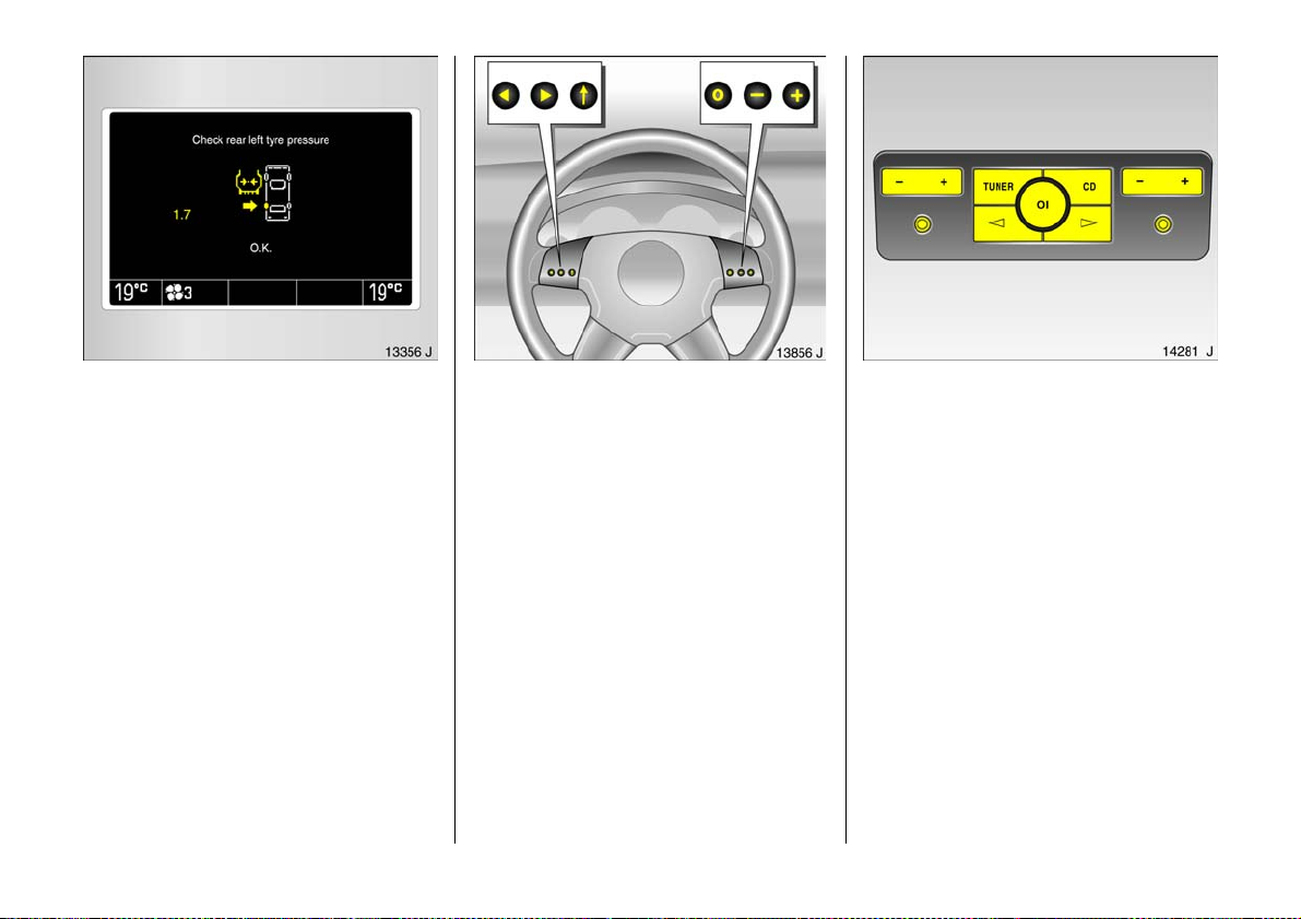
Check control 3
Check control monitors se veral fluid levels,
the tyre pressure 3, the radio frequency
remote control battery, the anti-theft alarm
system 3 and imp ortant external lights,
including the cables and fuses. In trailer
mode the trailer lig hting is a lso monitored.
6 Further in form ation – see page 4 6.
30
Remote control for radio and
Infotainment system 3
Radio 3, radio telephone 3 and
In fo t ain me nt sy ste m 3 functions can be
op erated with the b uttons on the steering
wheel.
For further inform ation, see the respectiv e
op erating instructions.
Twin Audio 3
Twin Audio provides rear seat occupants
the op portunity to listen to a different
audio sourc e than the one selected by the
driver.
Two headp hone connections a re available
with separa te volume con trol.
For further information, see the respective
radio ope rating instructions.
Page 33
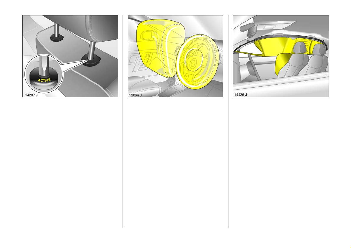
Active head restraints 3
In the event of a re ar-end impa ct, the
active head restraints automatically tilt
forwards. The head is more effectively
supported by the head restraint and the
danger of hyperex tension in the neck area
is reduce d.
Active head restraints are id entified by the
lettering ACTIVE on the head restraint
guide bushes.
Vauxhall Full-Size airbag system
The Vauxhall Full-Size airbag system
co m p r ise s seve ra l ind ividu al s yste m s .
Fro n t a irbag sy s tem
The front airbag system will b e triggered in
the event of a serious accide nt involv ing a
frontal impa ct and forms sa fety cush ions
for the driver and front passenger. The
forward movement of the driver a nd front
passenger is checked and the risk of
injuries to the upper body and he ad
thereby substantially re duced.
Side airbag system 3
The side airbag system triggers whe n a
side-on collision occurs and provide s a
saf ety barrier fo r the dri ver a nd/or
passenger in the respective front door
area. This reduces the risk of injury to the
upper body cons idera bly in case of a s ide
impa ct.
Curtain ai rbag system 3
The curtain a irba g system triggers in case
of a side-on collision and provid es a safety
barrier in the hea d area on the respective
side of the vehicle. This reduces the risk of
injury to the head considerab ly in case of a
side-on collision.
6 Furth er information – see page 100.
31
Page 34
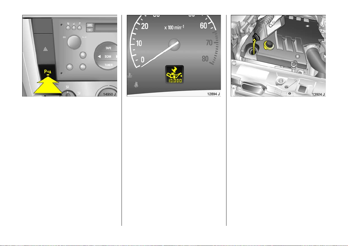
Parking distance sensors 3
The parking distance sensors front and
r ea r sy st e m s ar e a ut o m at ic al l y sw i tc he d on
when d riving in reverse ge ar.
The parking distance sensors can also be
switched on and of f m anually u sing the r
bu tto n o n th e in st r u me nt p a n el .
If the vehicle approaches a n ob stacle to
the front or rea r, a series of signals is
sounded in the vehicle interior. The interval
be twee n t he s ig n a l s beco me s sh orter a s
the d istance is reduce d. If the dista nce is
less than 30 cm , the signal will b e
continuous.
6 Further in form ation – see page 1 74.
32
ECOService-Flex
The oil ch ange and service intervals are
flexible, base d on a nu mber of different
parameters and the conditions under
which the vehic le is used. Various engine-
specific data is continuously recorded an d
used to calculate the remaining distance
up to the ne xt inspection date.
The rem aining driving dis tance can b e
seen in t h e tachom ete r di sp la y whe n the
ignition is off: press the reset button under
the trip odometer; v and the remaining
driving dista nce will then be displayed.
With the specially developed engine oil for
ve h icl es wit h EC OService -Fle x, the n ex t
engine oil change is due after a maxim um
of 2 ye a r s o r 25 ,0 0 0 m iles / 35,0 00 k m
(petrol e ngine) or afte r a max imum of 2
years or 30,000 miles / 50,000 km
(diesel engine)
When topping up the oil, alwa ys use grade
GM-LL-A-025 or GM-LL-B-025 in order to
ma intain the flexible maintenance
intervals.
6 Further information – see pages 234, 251.
Page 35
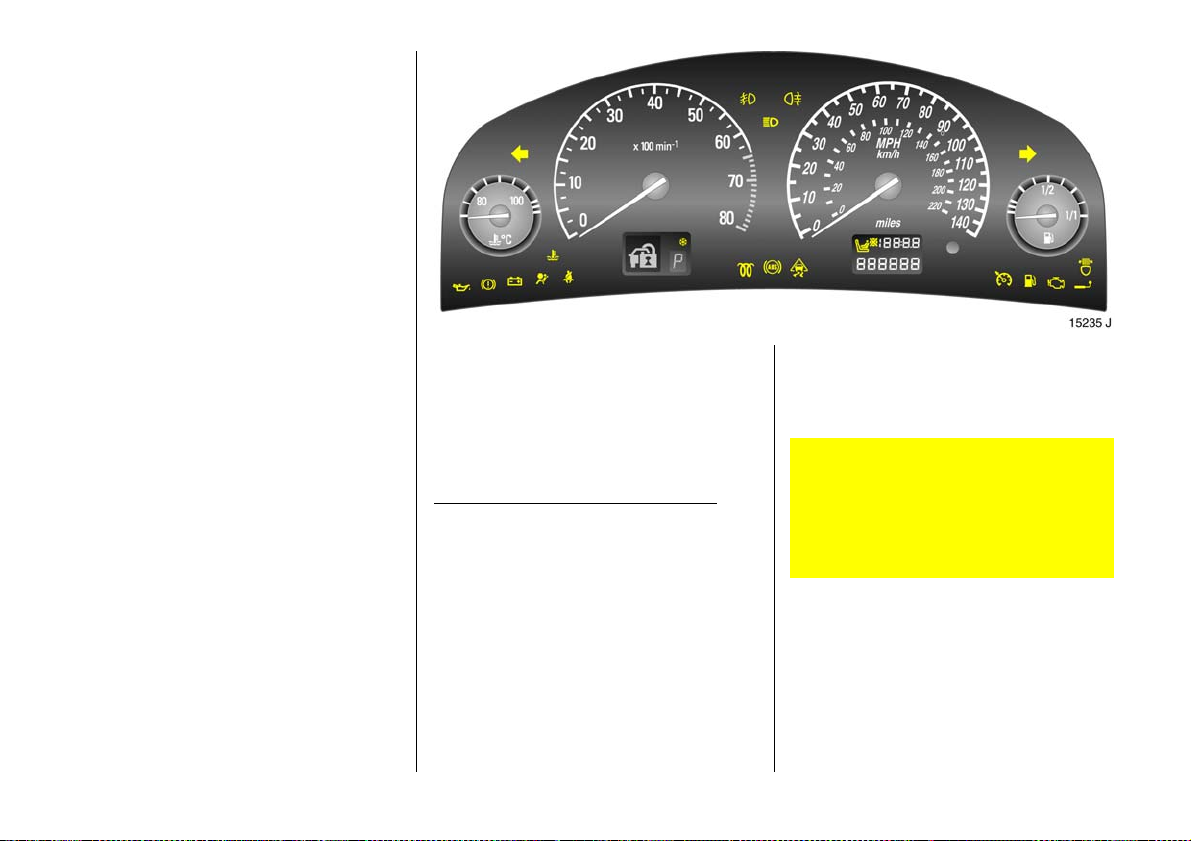
Instruments
Control indicators
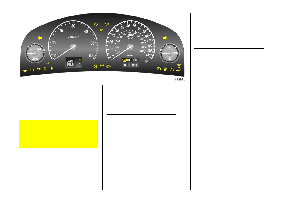
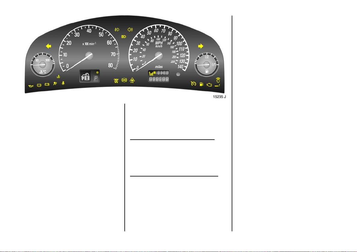
The c ontrol indicators described here are
not present i n all v eh icles . T h e de s crip tio n s
however, apply to all instrument versions.
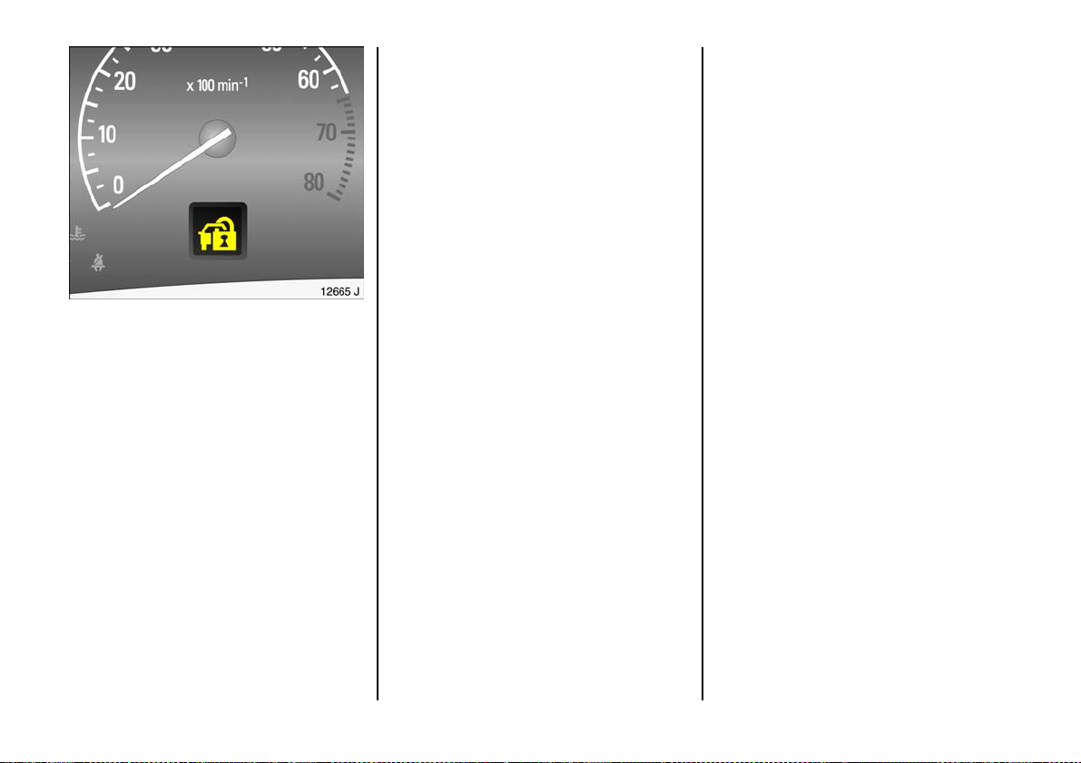
Some control indicators are shown a s
pictograms within the tachometer dial
area.
O
Turn signal lights
The corresponding control indicator
flashes when the turn signal is on. If the
hazard warning lights are activated, both
control indicators flash. Rapid flashes: a
turn signal bulb or its associated fuse has
failed. Changing bulbs – se e p age 218,
fuses – see page 2 12.
I
Oil p re ssure
Control indica tor lights up when ignition is
switched on. Goes out shortly after engine
starts. C an light up inte rmittently when
idling with hot engine; must g o out w hen
engine speed is increased.
Lig h ts up when the engine is running :
Engine lub rication may be interrupted. This
may result in dam age to the engine and/or
lock ing of the drive whe els:
1. Depress clutch.
2. Shift transmission to idling , with
automatic transmission 3 or CVTronic 3
move selector lever to N.
3. Steer as quickly as possible out of the
stream of traffic, without imped ing other
vehicles.
4. Switch the ignition off (Position I).
When the ignition is off, c onsiderab ly
more force is needed to brake and steer.
Do not remove key until vehicle has
come to a standstill, otherwise the
steering column lock c ould engage
un ex pe ct edl y .
Check oil leve l before consulting a
workshop. We recommend a Vauxhall
Authorised Repairer.
33
Page 36
v
Air b ag s y ste m s 3 ,
belt tensione rs 3
see page s 96, 105.
W
C ool ant temp era ture
Lights up when the engine is running:
Stop vehicle and switch off engine. Coolant
temperature is too high: switch off engine.
Danger to engine. Coolant fluid
temperature display – see page 40.
Check the coolant level immediately –
see page 238.
R
Bra k e sy s t em ,
clutc h syste m
The control indicator lights up when ignition
is switched on if handbrake is applied or if
brake / clutch fluid level is too low. Further
information – see pages 181, 240.
If it lights up when the handbrake is not
applied: stop the vehicle; interrupt your
journey immediately. Consult a
work shop. We recommend a Vauxhall
Authorised Repairer.
34
p
Alternator
Control indica tor lights up when ignition is
switched on. Goes out shortly after engine
sta rts .
Lig h ts up when the engine is running :
Stop, switch engine off. Battery is not
charged. Engine cooling may not be
op erating. With a die sel e ngine, the brake
servo unit may stop operating . Consult a
work shop. We recommend that you consult
a Vauxhall Authorised Re pairer.
Page 37

X
Seat b elt 3
The c ontrol indicator lights up when the
ignition is switched on and rem ains lit until
the seat belt is fastened. An acoustic signal
is also e mitted wh en th e car starts to move.
Fastening se at be lt – see page 9 8.
T
Winte r pro gr amme w ith autom atic
transm ission 3 or CVTronic 3
Control indicator lights up when winter
programme selected.
Further information – see pages 147, 155.
!
Preheating 3 for diesel engines
Control indicator lights up during
prehea tin g.
Preheating system switches on only if
outs ide temperatu re is low.
u
Anti-lock Brake System 3
see page 182.
v
Tr action Control system 3,
Electronic Stability Program me 3
see pages 168, 170.
>
Front fog lights 3
Control indicator lights up when front fog
lights are switched on.
r
Fog tai l light s
Control indicator lights up when fog tail
light is switched on.
P
Main beam
Control indicator lights up when ma in
beam is on and w he n headlight flas h is
operated.
y
Seat occupancy recogniti on 3
see page 1 05.
m
Cruise control 3
see page 1 72.
35
Page 38
B
Ad aptiv e Forward Lighting (AFL) 3
F au l t in sy ste m. C ons u lt a w o r k s h op. W e
recommend a Vauxhall Authorised
Repairer.
AFL – see page 118.
g
Trai ler turn s ignal li ght 3
Control indicator flashes in tim e with turn
signal lights when towing. Does not fla sh if
a turn signal light on the towing vehicle or
trailer fa ils.
Y
Fuel level
Lit: low fuel level. Fuel gauge in reserve
area.
If it flashes: fuel used up, fill up immediately.
Never let the tank run dry!
Petrol engines: erratic fuel supply can
cause catalytic conve rter to overheat –
see page 1 64.
Di es e l engin es : if the tan k is run d ry , ble ed
th e fu e l sy ste m as de scri b e d on pag e 19 9.
36
Z
Exhaust gases 3
Control indica tor lights up when ignition is
switched on. Goes out shortly after engine
sta rts .
Lig h ts up when the engine is running :
Fault in emission control system . The
permitted em ission limits may b e
exc eed ed. Co n su lt a wor ksh o p. We
recommend a Vauxhall Authorised
Repairer.
If it flashes when the engine is running:
For fa ult that ca n lea d to destruction of the
catalytic converter – see page 166. Consult
a workshop imme diately. We recommend
that you consult a Vauxhall Authorised
Repairer.
Page 39
Disp la y in ta c ho meter
o
Im mobil iser
Fault in electronic immobiliser, engine w ill
not start – see page 5 5. Consult a workshop.
We recommend tha t you consult a Vauxhall
Authorised Repairer.
p
Electro-hydraulic power assisted steering
Fault in electro-hydraulic steering system.
Power steering may not work. Vehicle can
still be steered, but considerably more
force is required. We recommend you
consult a Vauxhall Authorised Repairer.
?
Fault in automatic headlight range
adjustment system3
Contact a workshop immediately. We
re commend that you consult your Vauxhall
Authorised Re pairer – see page 117.
r
Parking distance sensors 3
see page 174.
A
E n g ine el ect ro n ics ,
tr a n sm is si o n ele ct r o ni c s
Fault in engine electronics or transmission
electronics. Electronics switch to
emergency running programme. Fuel
cons umption may increase and driveability
of the vehicle may be impaired – see
pag e 166. Fault in immobilise r system – see
pag e 55. Contact a workshop. We
recommend your Vauxhall Authorised
Repairer.
s
Bootlid open
Indicates the luggage compa rtment is
open. Close the luggage compartme nt –
see page 6 1.
37
Page 40

v
Airbag systems,
belt t ensioners
see page s 96, 105.
t
Bulb replacement 3
A bulb has failed. Check the lights, and
exchange the failed bulb . Bulb exchange –
see page 2 18.
F
Brak e lining wear indicat or 3
Front disk b ra ke pad worn to minimum
thickness. Contact a workshop to hav e
the b rake pads ch anged. We recomme nd
that you contact a Vauxhall Authorised
Repairer – see page 180.
S
Engine oil l ev el
Engine oil leve l too low. Check engine oil
level at the first opportunity. Engine oil
level – see page 236.
H
Coolant level
Coolant level too low, check the coolant
level immediately – se e pa ge 239.
v
Service in terv al
see page 234 .
x
Ty re pressure contr ol system 3,
loss of p ressure warning
Check th e pre ssure of t h e respec tiv e ty re
immediately – see page 1 76.
w
Ty re pressure control sy stem 3,
fault
see page 1 76.
y
Open doors
Indicates that one or more doors is open.
Close all doors.
P, R, N, D, 1 to 5
Automat ic transmission 3,
Selec tor lever position or mode selected see page 1 46.
P, R, N, D, A, 1 to 6
CVTronic 3,
Selec tor lever position or mode selected see page 1 53.
38
Page 41
Odo meter
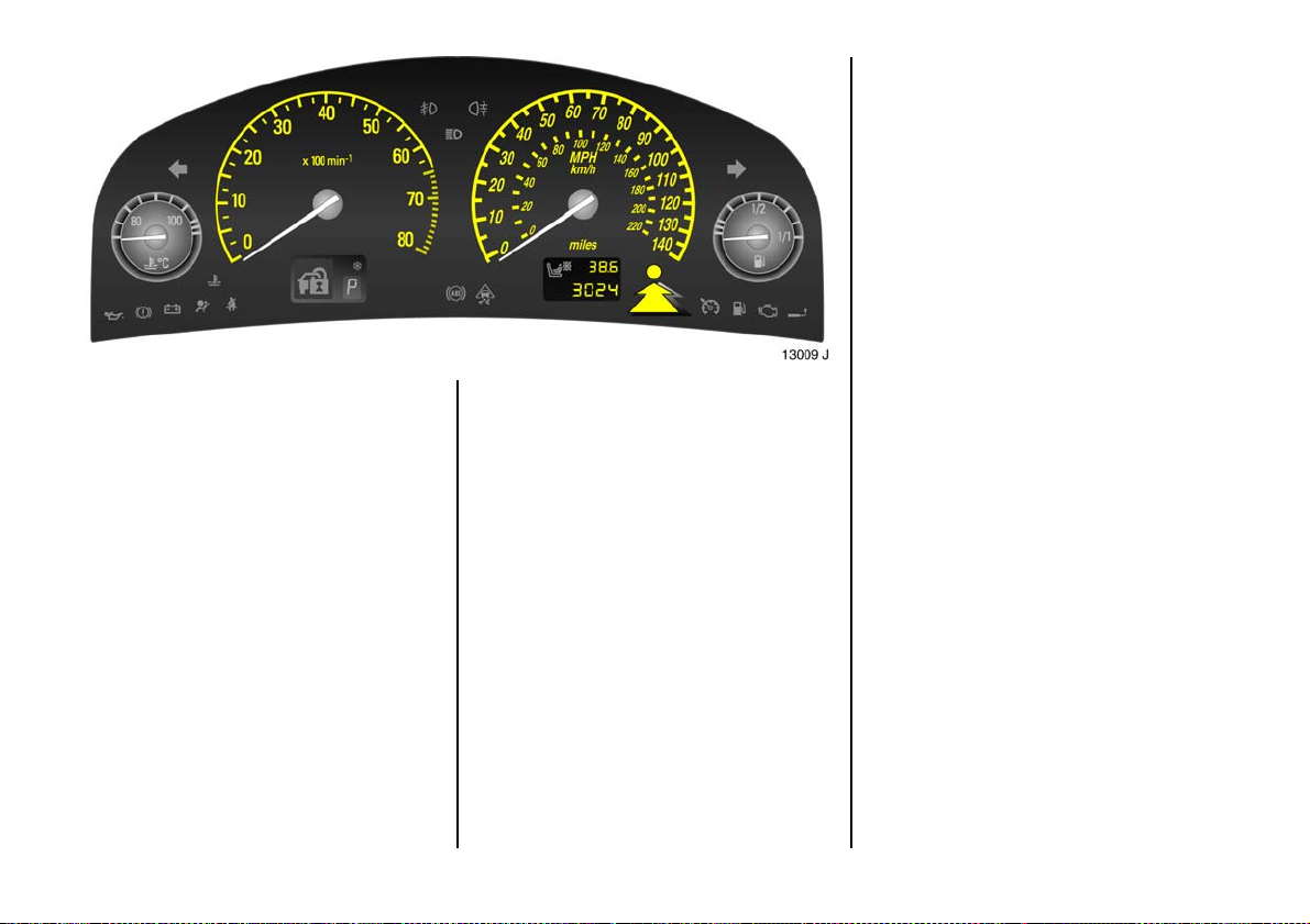
Records the miles / kilome tres driven.
Trip odometer
To return to zero, depress reset knob with
ignition switched on.
Service interv al display – see pa ges 3 2, 234.
Tachometer
1)
Indicates engine speed.
Warn ing zone: m aximum permissible
e ngine sp eed ex ceeded ; dan ge r to en gine.
1)
The inst rum ent s in your vehic le may d iffer
from the instruments illustrated here.
Spee dom eter1)
Indicates the vehicle speed.
39
Page 42
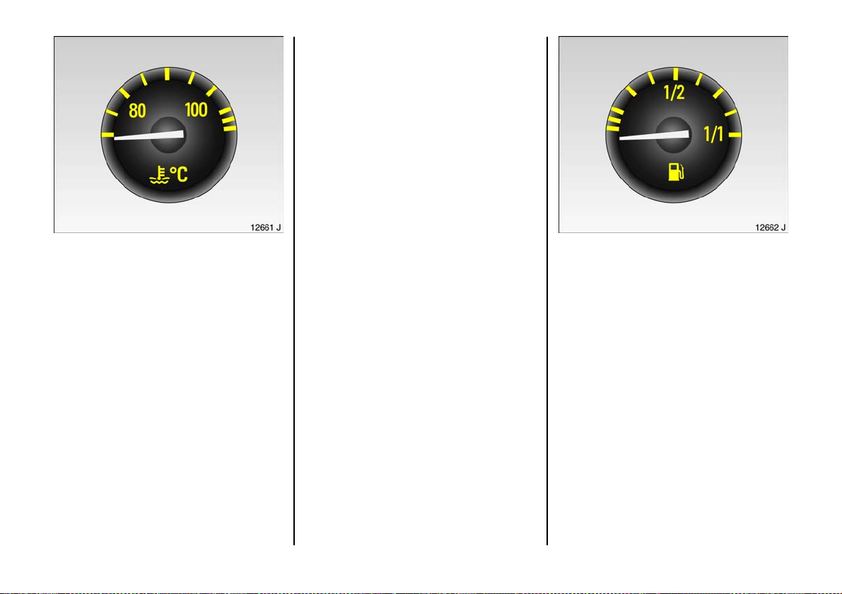
For physical re asons, the engine
temperature gauge shows the coolant
temperature only if the coolant level is
adequate.
Durin g oper ati o n the s ys tem is pr es su ris ed.
The temp erat u re ma y there fore rise b rief ly
to ov er 100 °C.
Co ol an t te mp era t ur e d i sp la y
Pointer in zone
at left = Engine operating
tem perature not
yet rea che d
Pointer between
the zones = Normal operating
temperature
Pointer in
warning zone
at right
or W is lit = Temperature
too high:
Stop, switch off
engine, danger to
engine, check
coolant level
immediate ly – see
page 2 39.
40
Fuel gauge
Pointer in left
zone or Y li t = R e s er v e ar ea
Pointer in left
zone or Y
flashing = Fill up –
Never run the tank dry!
Because of the fuel remaining in the tank,
the amount of fuel required to fill the tank
may be less than the specified tank
cap acity.
see pag e 16 3
Page 43
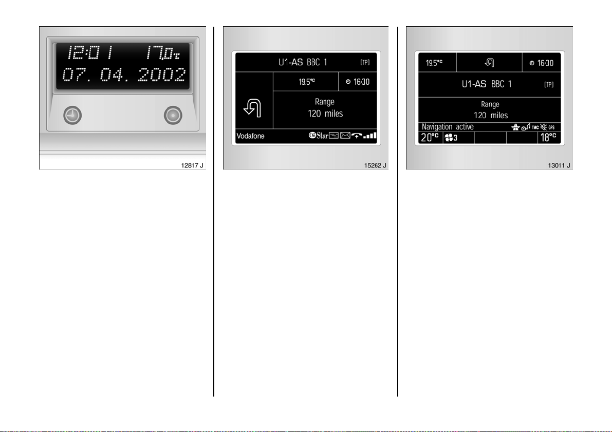
Inform ation display
Tripl e inform ation d isp lay
Display of time, outside temperature and
radio / date.
The tim e and outside temperature are
displayed when the ignition is on. The date
is displayed when the radio 3 is s witched
off.
When the ignition is off, the time, date and
ou tside tem peratu r e can be pres en ted f o r
1 5 se co nd s b y br ie fly pres s ing one of th e
two buttons below the displa y.
Display of --.- °C or F in the d isplay
indicates a fault. H ave the cause remedied.
We recommend that you consult a
Vauxhall Authorised Repairer.
Graphica l informa tion dis pla y 3,
Colour inform ation di sp lay 3
Display of date, time, outside tem perature,
and informa tion from che ck control 3,
trip computer 3, e lectronic air co nditioning
sy ste m 3, r adio 3 and Infotainment
sy ste m 3.
The g ra phical in form ation display presents
the info rmation in mono chrom e. T he colour
information display p resents the
information in colour.
The information displayed depends on the
vehicle equipment and the settings of the
trip computer 3, the electronic air
conditioning system 3, the radio 3 and the
Infotainment system 3.
Electron ic air con ditioning system – se e
pag e 134. For ope ration of the radio and
Infotainment system refer to the
acc ompanying ope rating instructions.
Display of --.- °C or F in the display
indicates a fault. Have the cause remedied.
We recommend that you consult a
Vauxhall Authorised Repairer.
41
Page 44
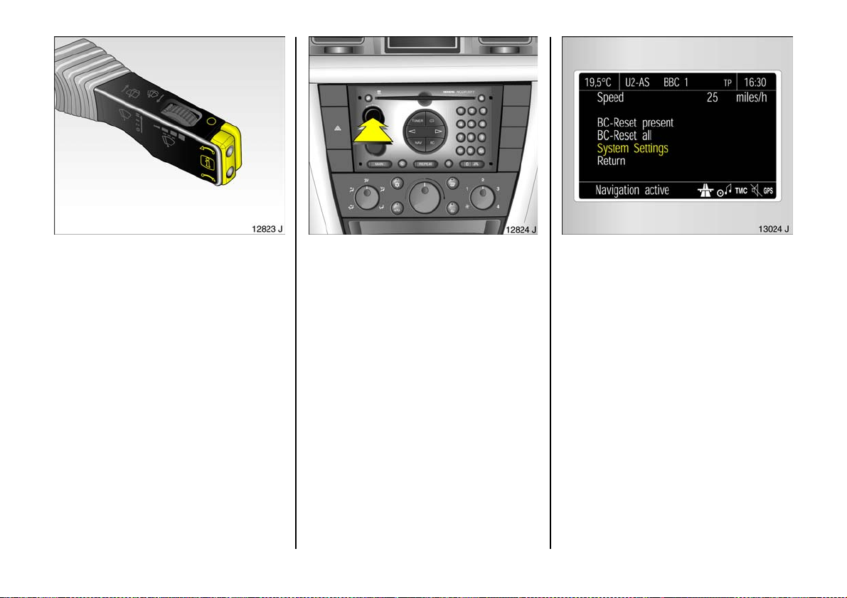
Operating the graphical information
display 3 o r th e co lour info rmatio n
display
The functions are activated using the
buttons on the wiper stalk or by using the
multifunction button if the vehicle is
equipped with a radio telephone 3 or
Infotainment system 3 – see Fig. 12824 J.
If check control issues a warning message,
the display is blocked from other functions.
Acknowledge the message with button §
on the wiper stalk 3 or by p ressing the
multifunction button. If there are several
fault war nings, ack nowledge them on e at a
time.
42
3
The trip computer functions are activated
using the menus on the display and the
buttons on the wiper sta lk 3 or via the radio
telep hone 3 or Infotainm ent system 3 .
Ac tivation using buttons on wiper stalk:
The individual menu items are selected
us i n g the h and i buttons and selected
by pressing the § button. To activate the
trip co mpu t er, pres s the § button .
Ac tiv ation using multi-function button: the
indiv idual menu ite ms are selected by
rot a tin g and se l ec t e d b y pr es sin g. P r es s B C
button on system to activate the trip
computer.
System settings
Th e figures show execu tion wi th th e c olo u r
inform ation display.
In the trip computer settings menu, select
Syste m Se tti ngs.
On vehicles without trip computer, press
button § on the wipe r stalk 3.
The system s ettings menu will b e
displayed.
Page 45
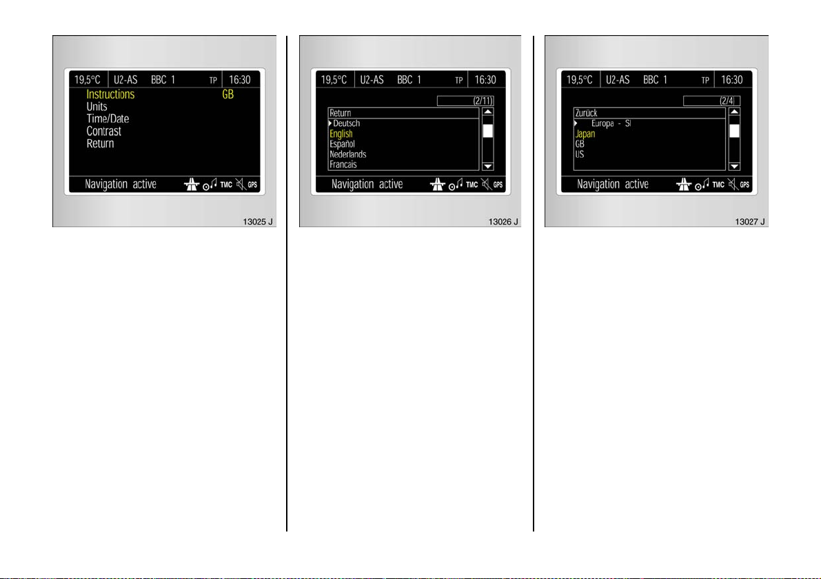
Language selection
You ca n select the display language for
som e functions.
In the Syste m Set tings me nu, select item
Ins truct ions .
The list of availab le languages will be
displayed.
Select the required languag e from the list.
Selections are indicated by a 6 in front of
the menu item.
Setting units of measure
You can select which units of measure are
to be used.
In the System Se ttings m enu, select item
Units.
Selec t from the list of units that ope ns.
Selec tions are indicated by a 6 in front of
the menu item.
43
Page 46
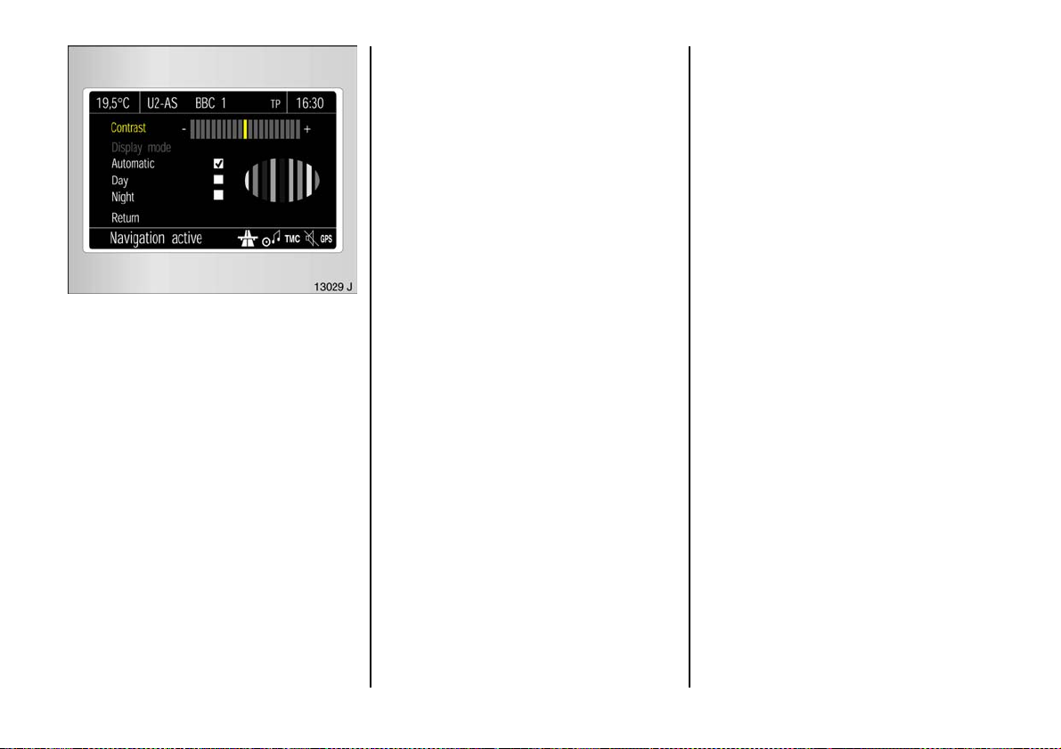
Adjust contrast
In the Syste m Set tings me nu, select item
Cont rast.
The c ontrast menu w ill be d isplayed.
Confirm the required se tting.
Set displa y m ode
The display can b e adjuste d to suit the light
conditions, b la ck or coloured text on a light
background or white or coloured text on a
dark background.
In the Sy s tem Setti ngs menu, select item
Automatic, Day or Ni ght.
Automatic: Adjustment depending on
vehicle lighting.
Da y: Black or coloured text on light
background.
Night: W hite or coloured te xt on dark
background.
Setting date and time
In systems with a GPS receiver1)
(Infotainment system 3, radio telephone
with GPS m odule 3) the time and date are
automatically set when a GPS satellite
signal is received. If the displayed time
does not ma tch the local time, the time can
be corrected by making manual entries in
steps of 30 minutes or automatically by
receiving an RDS time signal2) 3.
In radios without a GPS receiver, the time
and d ate can be adjusted manually or
automatically using the RDS time signal 3.
Som e RDS transmitters d o not send correct
time signals. If the incorrect time is
displayed often, deactivate the automa tic
time synchronisation 3 and set the time
ma nually.
The automatic setting is indic ated b y Ö in
the display .
44
1)
GPS = Global Positioning System,
Satellite syste m f or world- wide p osition in g.
2)
RDS = R adio Data System.
Page 47
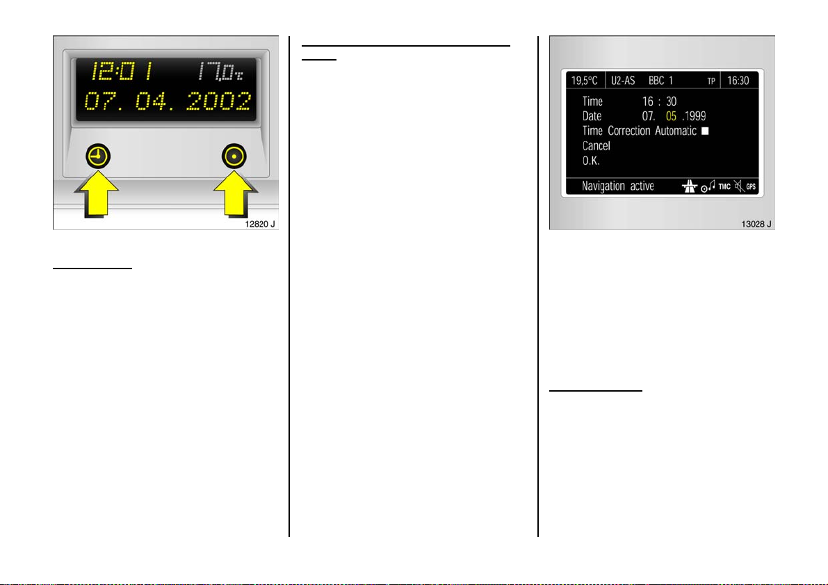
Deactivating a nd activating automatic
setting
Hold down Ö for approx. 2 sec., c lock
display is now in setting mode.
Pre ss Ö twice (until year flashes).
Press and hold down Ö for approx.
3 seconds until } flashes in display and
text "RDS TIM E" appears (years fla sh
during this time).
Display indicates:
RDS TIME 0 = Deactivated
RDS TIME 1 = Activated
Pre ss Ö three times.
Vehi cles with tri ple informat ion dis pla y
Manual setting
Switch off radio. Press Ö and ; be low
display a s follows :
Press Ö for ap prox. 2 seconds:
Day flashes
;:Set day
Ö:Month flashes
;:Set month
Ö:Year flashes
;:Set year
Ö:Hours flash
;:Set hours
Ö: Minutes flash
;: Set minutes
Ö: Clock is started.
Ve hicles with gr aphical informat ion
display 3 or colour inform ation d isp lay 3
In the System Se ttings menu, select item
Time / Date.
The menu for time / date will be displayed.
Selec t the menu items re quired.
Make the desired settings and confirm.
Selec t menu item OK.
Correcting time 3
To correct the time, use RDS in the Time /
Date me nu to select item Auto. Time
Correction.
Th e field be h ind Au to. Time Corre cti on will
be ticked.
45
Page 48
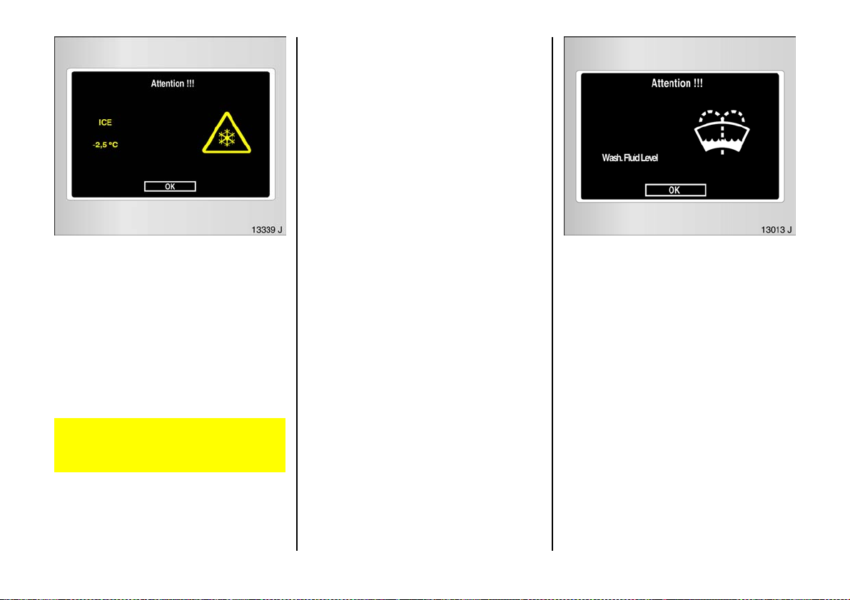
Outside tempe rature
A fall in temperature is indicated
immediately and a rise in temp erature
after a time delay.
On vehicles with triple information dis play,
the symbol T is shown in the display from
3 °C as a warning for icy road surface s.
On vehicles w ith gra phical information
display 3 or c olour information display 3 a
me ssag e is sh own in the d i splay t o war n fo r
icy road surface s. See figure.
Caution: The road surface may already
be icy even though the display indicates
a few degrees above 0 °C.
Check control 3
Check control monitors several fluid le vels,
the tyre pressure 3, the radio frequency
remote control batteries, the anti-theft
alarm system 3 and im portant external
lig hts, including the cables and fuses. In
tra iler mode, the trailer lighting is also
monitored.
Once the ignition has be en switched on, all
check control functions are autom atically
verified.
Fault warnings appe ar on the display. If
there are several fault warnings, they are
displayed one after the other.
Some of the fault warnings appear on the
display in an abb reviated form.
Ac know ledge fault displays as describe d
on p age 42.
Fau l t war n i n g s :
Che ck r em ote control
battery
If battery volta ge of the remote control unit
is too low – see page 57.
Che ck b rake lig ht switch
Fault. Brake light does not come on when
brak e applied. Have caus e of fault
remedied imm ediately. We recom mend
that you consult a Vaux hall Authorised
Repairer.
Check safeguard
Fault. System error in anti-theft alarm
system. Have cause of fault remedied
imm ediately. We recomm end that you
consult a Vauxhall Authorised Repairer.
46
Page 49

If there is a fault in the lighting system, the
respective location of the fault is displayed
as text, e.g.:
Check right brak e
light
If brake light is defective, the relevant tail
light takes ov er the brake light function.
Bulb e xchange – see page 218.
If tyre pre ssure is too low, the display
indicates the tyre to check, e.g.:
Check rear r ight
tyre pressur e
Check ty re pre ssure at next opportunity,
using suitable tyre pressure gauge. Tyre
pr e ssure con t r o l sy ste m 3 – see page 176.
Checking tyre pressure – se e page 184.
If there is major loss of pre ssure in a tyre,
the display indicates the tyre a t fault, e.g.:
Rear left tyre
pressure loss
Stop immediately and check tyre. Tyre
pr e ssure con t r o l sy ste m 3 – see page 176.
Che ck w ash fluid le vel
Fluid level in windscreen wash system too
low . Top up wa sh fluid – see page 242.
Rear window wash system 3 and h eadligh t
wash system 3 are deactivated if wash
fluid is low.
Interruption of power supply
The check control 3 autom atically checks
all functions after the battery has been
reconnected or charged. Stored fault
warnings appe ar on the display one after
the other.
47
Page 50
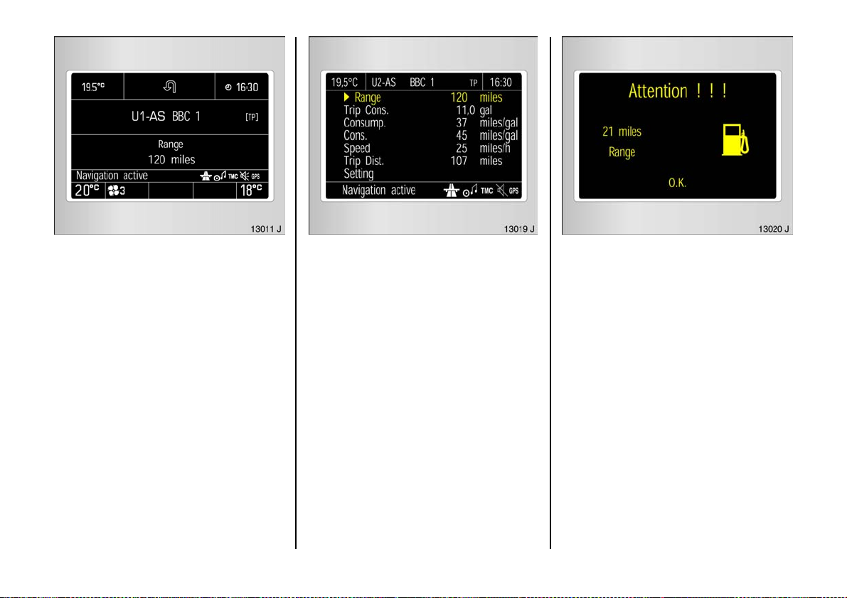
Trip comp ut er 3
Th e trip compu ter s h ow s vehicle data
which it continually records and e valuates
electronically.
Some of the functions appear on the
display in a n abbrev iated form.
Functions:
z Rang e,
z Effective consumption,
z Av erage consumption,
z Instantaneous consumption,
z Average s p ee d ,
z Dis ta n ce,
z Settings.
Check control warnings always have
priority.
48
Range over 30 miles (50 km)
Range is calculated from current fuel ta nk
content and instantaneous consumption.
The display shows average values.
The ra nge updates automatically after a
brie f dela y after the v ehicle h a s b een
ref ue lle d. Manual u pdating is also pos sible –
see page 50.
Ra ng e b el ow 30 m iles (50 km)
If the fuel in the tank will allow less than 30
miles (50 km), a warning "Range " appears
on the display.
Page 51
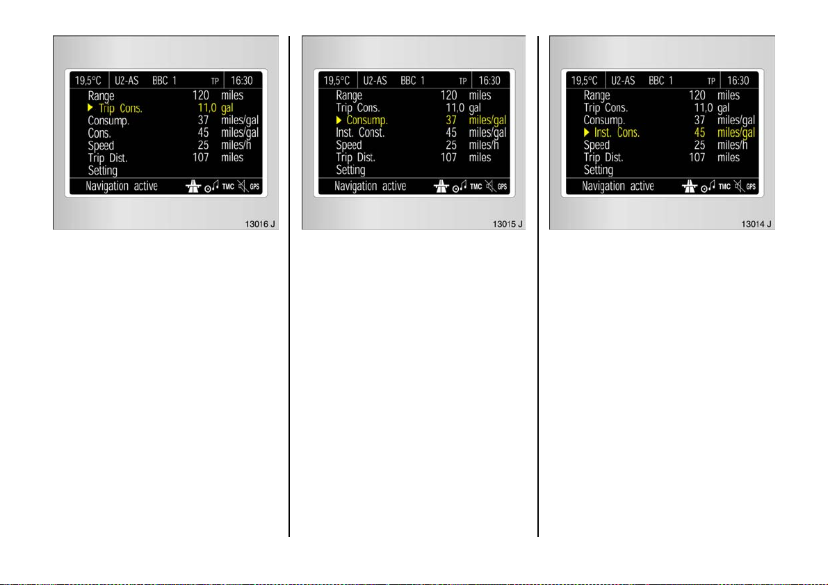
Effective consumption
Shows the a mo unt of f u el consu m ed . Th e
measure ment can be restarted at any time
– see page 50.
Average consumption
Calculation of avera ge consumption. The
measuremen t can be restarted at any time
– see page 50.
Instantaneous c onsump tion
Display c hanges depending on speed:
Display in g al/h below 8 mph
(13 km /h),
Display in m pg above 8 mph
(13 km/h).
49
Page 52
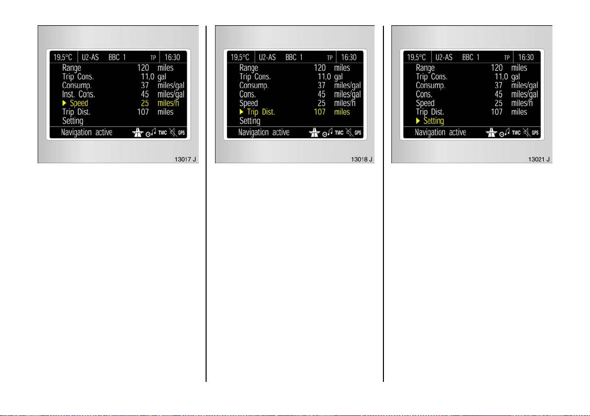
Ave r ag e sp ee d
Average speed calculation. Measurement
can be restarted at any time,
see right-hand column.
Stoppag es in the journey with the ignition
off are not included in the calculations.
50
Distance trav elled
Display s numbe r of miles (kilometres)
driven. Measurement can be restarted at
any time, see right-hand column.
Res et current trip comput er informati on
The following trip com puter in formation
can be reset (restart measurements):
z Range (only with vehicle stationary),
z Effective consumption,
z Average consumption,
z Average s p ee d ,
z Distance travelled.
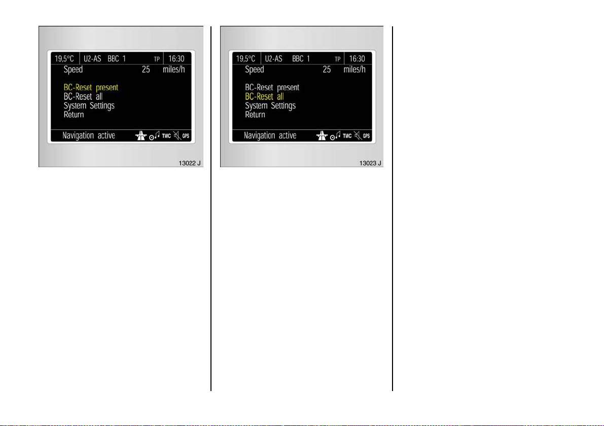
Select the required items from the trip
compute r me nu.
Then select me nu item Settings .
The Settings menu is displayed.
Page 53
Interruption of power supply
If the power supply has been interrupted or
if the battery voltage has dropped too low,
the values stored in the trip computer w ill
be lost.
Select BC Reset present in the Settings
menu.
The v alue for the selected function will b e
reset and recalculated.
The range value s can only be reset if the
vehicle is stationary.
After resetting, "- - -" is displayed with the
trip computer information selected. The
recalculated values are d isplayed after a
brief delay.
Resetting multip le informat ion on
the trip com pute r
The following trip computer information
can be reset simultaneously (restart
measurements):
z E ffective consumption ,
z Average consumption,
z Average speed,
z Distance travelled.
Select menu item BC Reset all in the
Settings me nu.
The v alues are rese t a nd "***" is d isplayed.
New values are only displayed when the
engine is running. The average speed is
calculated shortly after starting to drive.
51
Page 54
Radio 3
The rad io is operated as described in th e
opera ting instructions supp lied.
The d isplay for the radio ap pears on the
information display .
Car radio reception differs from domestic
radio reception:
As the vehicle aeria l is relatively near the
ground, the broadcasting companies
cannot g uarantee the sa me quality of
rece ption a s is obtain ed with a domestic
ra dio using an ov erhead aerial.
z C hanges in distance from the
transmitter,
z Multi-path reception due to reflection
and
z Shadowing
may cause hissing , noise, distortion or loss
of reception altogether.
Infotainment system 3
The Infotainm ent system is operated as
described in the ope rating instructions
supplied.
Depend ing on the v ersion, the Infotainm ent
system co n ta i ns tel e matics (tel ep hone).
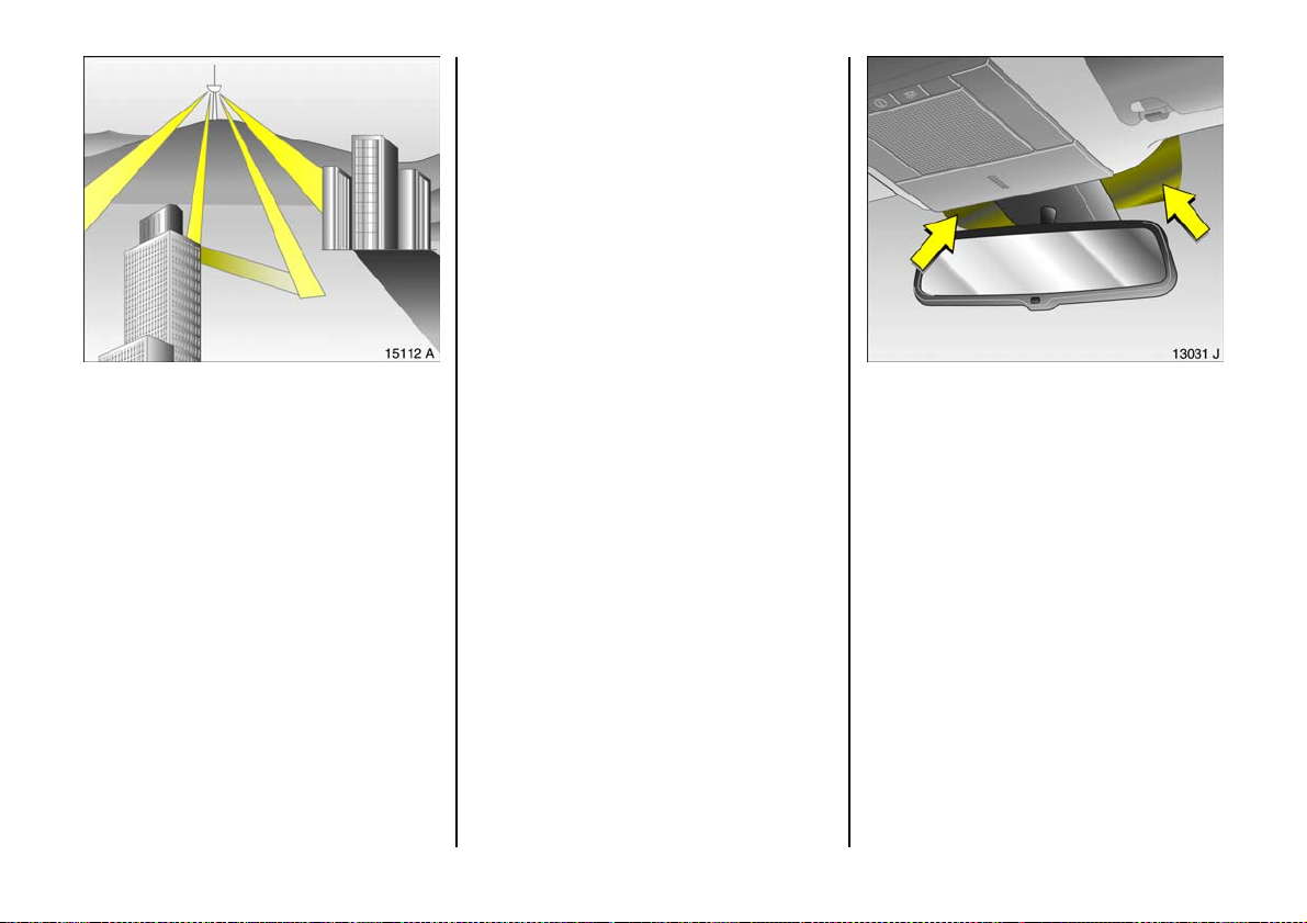
El ectr onic data acqui sitio n in toll
sys tem s 3
O n ve hicle s wi t h he a t - r efle ct in g
windscreens1) 3, mount the chipcard 3 for
electronic data a cquisition and billing in
the black sh aded zone of the windscreen
on the left or the right behind the interior
rear-view mirror, see figure. If the chipcard
is mounted outside this zone, malfunctions
ma y occur in data acquisition.
52
1)
Solar Reflect.
Page 55

Mobile telephones and radio
equ ipment (CB)
The Vauxhall installation ins tructions and
the operating gu idelines provided by the
telephone manufa cturer must be observed
when fitting and operating a m ob ile
telephone. Failure to d o s o could invalida te
th e v ehicl e’ s op erating pe rmi t
(EU Directive 95/54/EG).
Prerequisites for fault-free operation:
z Professionally installed exterior aerial to
ob tain the max imum range possible,
z Maximum transmission power 10 Watt,
z Installatio n of the t elephon e in a s uitable
spot (see note on pag e 107).
3
Obtain advice on predetermined
installation locations for the external
antenna an d equipment holde r and ways
of using devices w ith transmission power of
more than 10 Wa tts. We recom mend that
you consult a Vauxhall Authorised
Repairer, who will have brack ets an d
various installation k its available as
accessories and will install them in
accordance with regulations.
Be sure to use the handsfree attachment if
us ing the telepho ne w hilst drivin g. Ev en this
can be a distraction while driving. Please
ob se r ve count ry-spec ific re gulati o ns.
When used in the vehicle interior, mobile
telephones and radio equipment (CB)
with integrated ae rial may cause
malfunctions in the vehicle electronics.
Mobile telephones and radio equipm en t
(CB) s hou ld only be used with an ae rial
fitted on the vehicle e xterior.
53
Page 56
Keys, doors, bonnet
Re pl ace men t k e ys
The key is a c onstituent of the electronic
immobiliser. Ordering keys fr om a Vau xhall
Authorised Re pairer g uarantees problem free operation of the electronic
immobiliser. You will avoid unnecessary
costs, difficulties with insurance comp anie s
when proce ssing claims and problems
asserting wa rranty claims .
Ke ep th e spar e k ey acces sib le in a safe
place.
Locks – see page 24 8.
Lock cylinders
Des igne d to f re e-wh e el if they a re
forcefully rotated without the corre ct key or
if the correct key is not fully inserted.
To reset, turn cylinder with the correct key
until its slot is vertica l, remove key and then
re-in sert it. If the cylinde r still free-wheels,
turn the key through 180° and repeat
op er at io n .
Ch ild sa fety loc k s
Use the child safety lock whenever
children are occu pying the rear seats.
Disregard may lea d to injuries or
en dan g e r li fe. Ve hi cl e p ass en ge r s sho u ld
be informed accordingly.
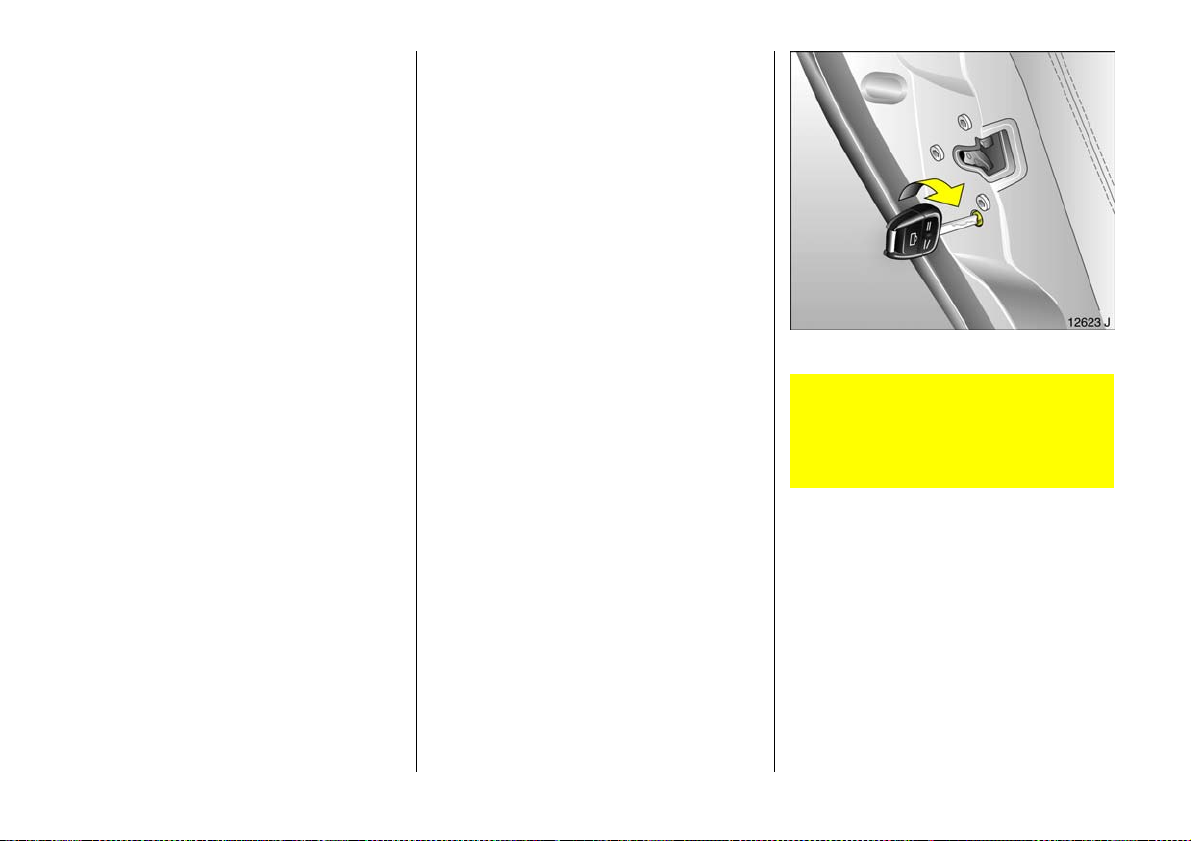
Using key, turn lever on rear door lock from
the vertical position: door cannot then be
opened from inside.
54
Page 57
Electronic immobiliser
The sy stem checks whether the vehicle m ay
be started using the key that has been
inserted. If the k ey is recognised as
"authorised" the vehicle can be started.
The c heck is carried out via a transponder
housed in the key – see page 5 6.
To activate:
Switch off engine, turn key to position 0
and re move .
To deacti vate :
Turn key to position II (ignition on); the
engine can then be started.
Deactivation is not possible in any other
way, so ke ep spare key accessible in a safe
place!
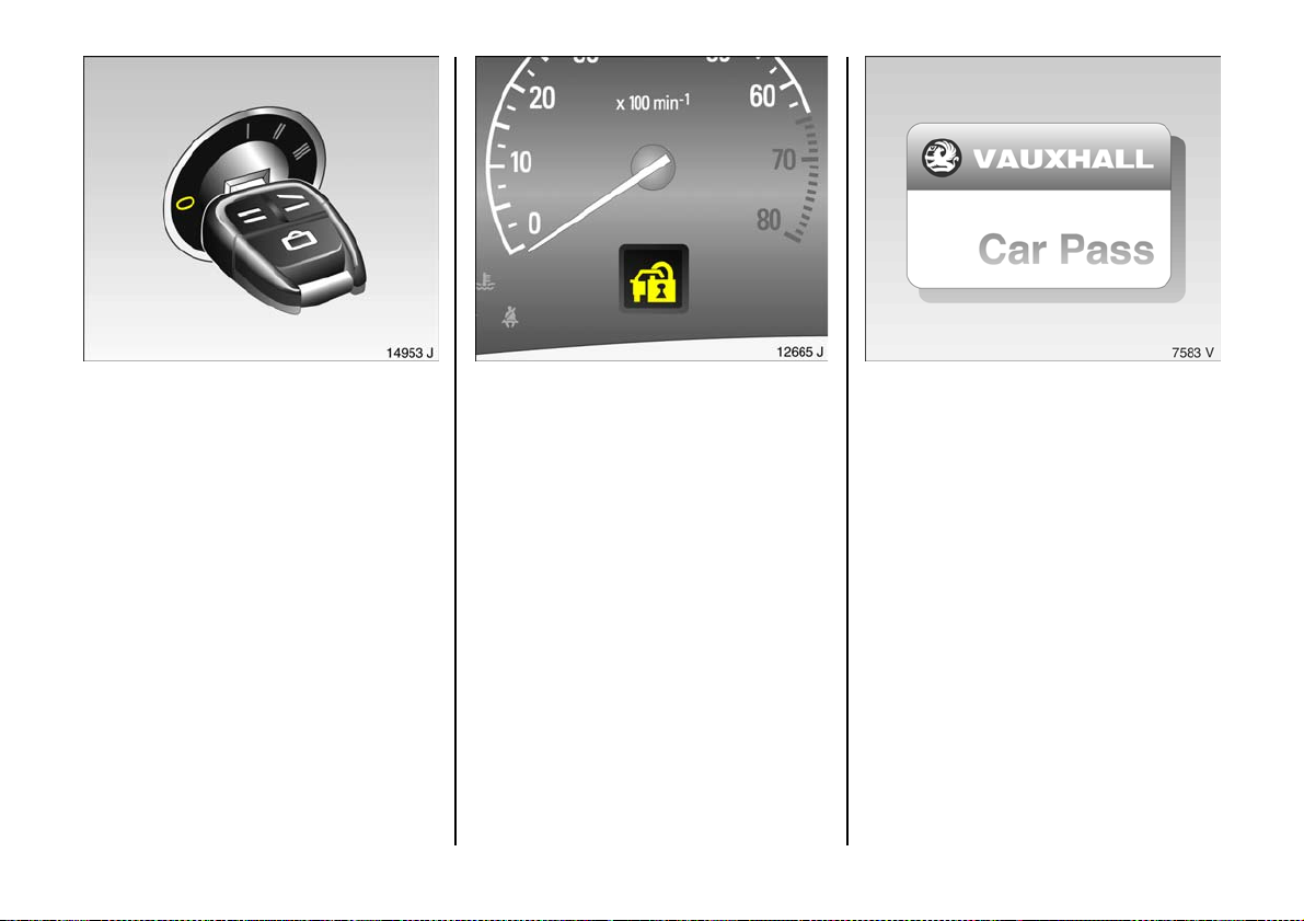
Control i nd icator for imm obiliser
If control indicator o lig h ts when th e
ignition is s witched on, the key is not
recogn i se d by the s ys t em and t h e engi n e
cannot b e started:
1. Turn key to 0 in the ignition and remove.
2. Re insert key in ignition switch .
3. Then repeat starting proce dure.
If the control indicator o remains lit, try to
start the engine using the spare ke y and
consult a workshop. We recommend a
Vauxhall Authorised Repairer.
If the control indicator flas hes whilst the
ignition is on A , there is a fault in the
engine electronics. The engine cannot be
started – see page 166.
Not e
The immobiliser doe s not lock the doors.
Therefore, after leaving the vehicle always
lock it and switch on the anti-theft alarm
system 3 – see pages 58, 63.
Th e Car Pas s conta ins al l of t h e vehicle ’s
data and should therefore not be kept in
the vehicle.
Hav e y our Car P as s o n ha n d w h en
consulting a Vauxhall Authorised Repairer.
55
Page 58
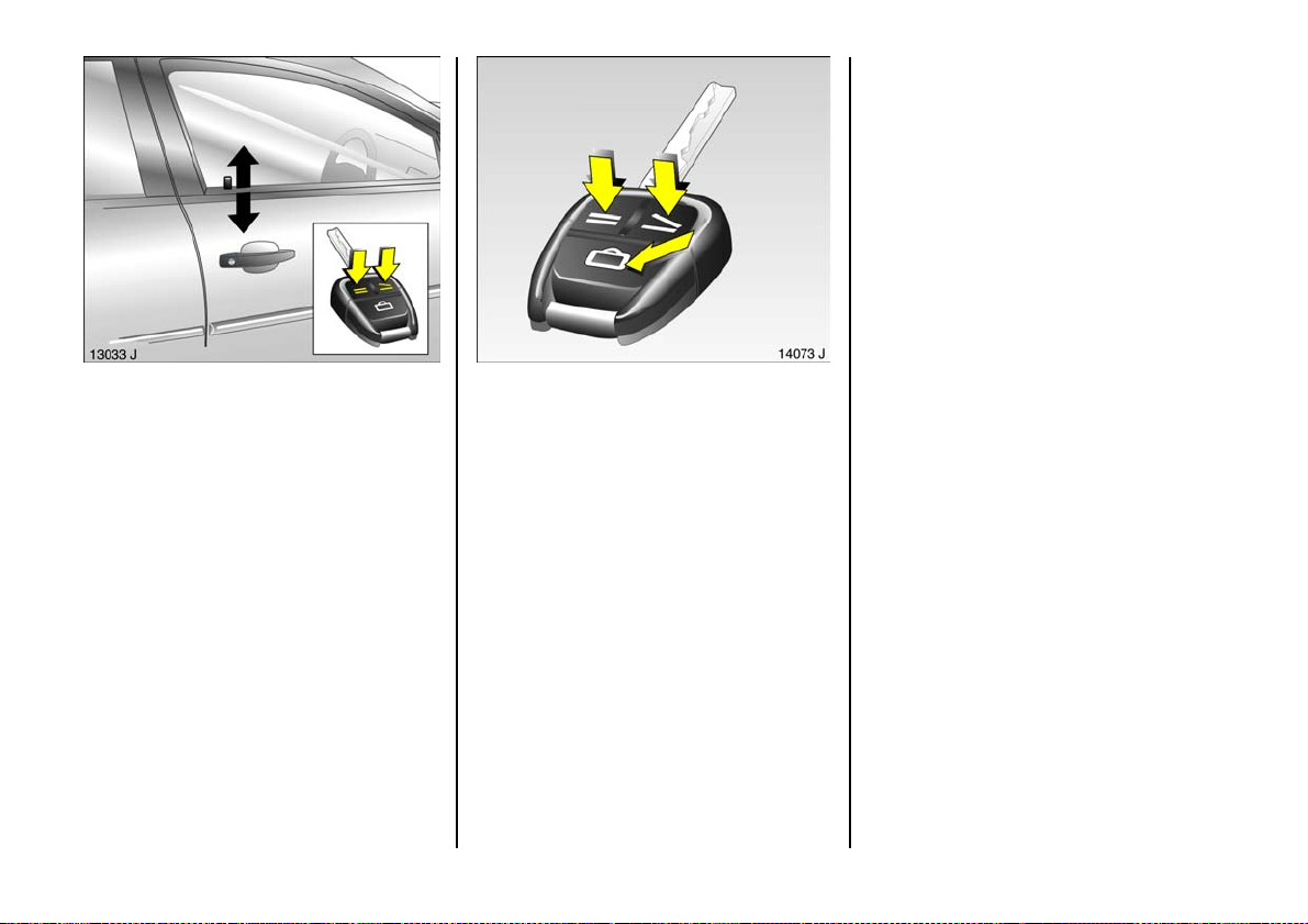
Radio fre q uen cy re mot e co ntro l
The radio frequency remote control is
integrated in the key.
Us ed to op erate
z central locking s ystem,
z mechanical anti-theft locking s ystem 3,
z boot lid , tailgate ,
z Vauxhall alarm system 3 .
Electric windows can be opened and
closed 3 using the remote control unit. The
electric sun roof 3 can be closed using the
remote control unit.
The remote control has a range of approx.
3 metres. The range can be affected by
external influences. Point the remote
control at the vehicle when opera ting.
For your convenience, we recommend that
the central lock ing sy stem always be
op erated using the remote control unit.
Handle remote control with care, protect
from moisture and h igh temperatures and
avoid unnecessary operation.
Function check by brief illumination of
ha zard warning flashers.
Position memory on vehicles with
electric ally operated front seats 3
W h en the veh icle is loc ked usin g the ra dio
frequency remote c ontrol, the current
position of the driver’s seat and the exterior
and interior mirrors are stored. Personal
settings saved using various radio
freq uency remote controls can be retrieved
as follows: open driver’s door within one
minute of unlocking and the positions
stored using the radio frequency remote
control are automatic ally set – see
pag e 80.
C entra l locking s yste m,
see page 5 8.
Mechanic al anti -theft locki ng system 3 ,
see page 5 8.
Boot lid or tailgate,
see page 6 1.
Vauxhall alarm system 3,
see page 6 3.
Electric windows 3,
see page 1 20.
Electrica lly op era ted sun roof 3,
see page 1 23.
56
Page 59
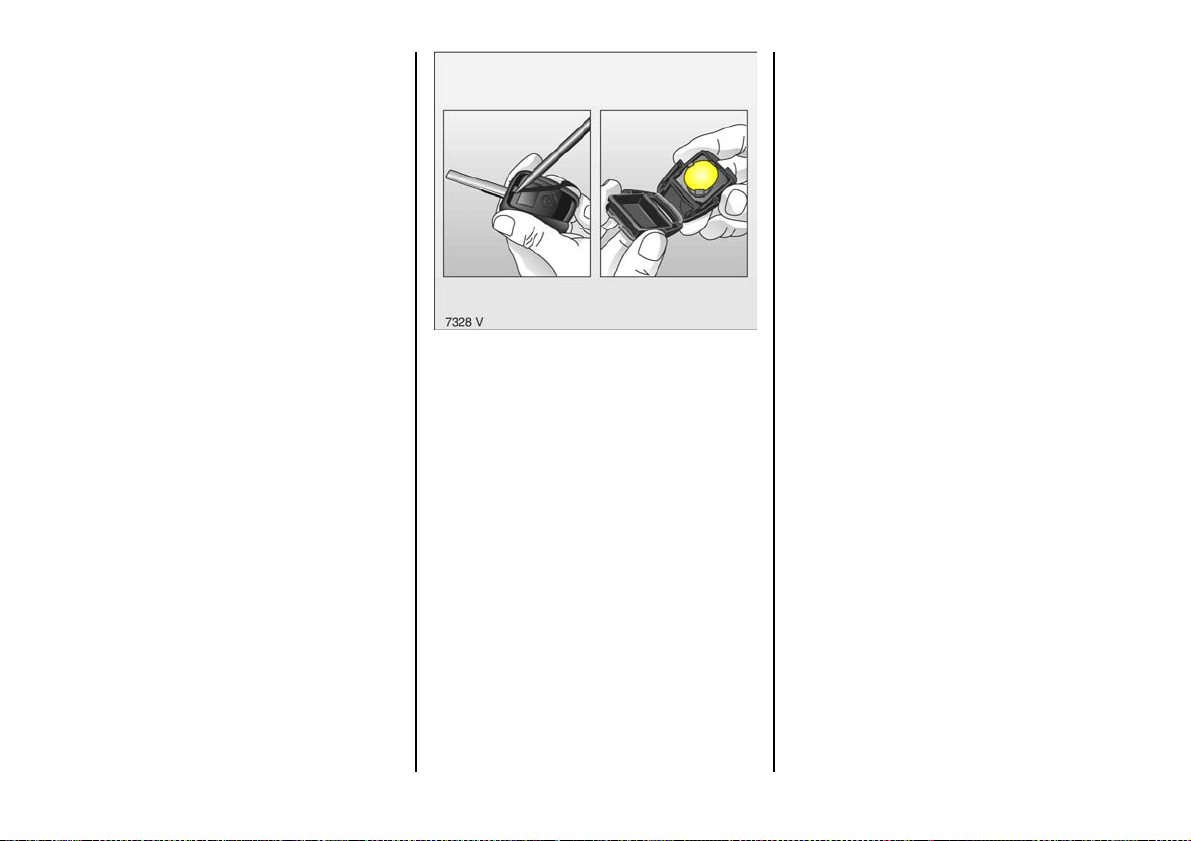
Fault
If the central locking system cannot be
operated with the re mote control, it may b e
due to the following:
z The range of the remote control has
been exceeded.
z Remote control battery voltage too low,
cha nge batteries, see next column.
z Frequent, repeated operation of the
remote control outside the reception
ra nge of the vehicle (e.g. too far from
vehicle, remote control is then no longer
recognised). To synchronise remote
control, see next column.
z If the central locking system is
ov erloaded as a result of repeated
op eration at short intervals, the power
supply is cut off for approx . 30 seconds.
z Inte rfer en ce from h igh er -po we r radio
waves from other sources.
For central locking system ope ration using
key – see following pa ges. Ha ve cause of
fault remedied. We recommend that you
consult a Vauxhall Authorised Repairer.
Make sure that you dispose of old batteries
in accordance with environmental
protec tion regulations.
After replacing batteries, synchronise
remote control: unlocking door using key
in lock – s ee next page. Insert key into
ignition.
Changing the remote co ntrol ba ttery
Exchange the battery as soon as the range
of the remote control starts to become
reduced.
Insert a small screwdriver in the notch in the
clip and lift. Pull the k ey part from the
re mo t e c o nt r o l .
The transponder for the immobiliser is in
the front of the key. Make sure that it is not
damaged or detached.
Open the remote c ontrol. Replace the
battery, e nsu ring th at it is inserted correctly
(se e pa ge 275 regarding b attery type).
Close the remote control, insert it in the key
part and make sure it audibly engages.
57
Page 60
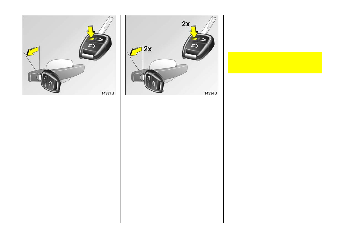
Turn key in driver’s door lock towards rear
of vehicle ag ain within 10 seconds after
locking, then turn it back to the vertica l
position a nd remove.
Lock buttons on all doors are positioned
such that doors cannot be opened.
Do not use the sy stem if there are people
in the vehicle! The doors cannot be
unlocked from inside.
Cen tr al l oc king sy stem
For doors, boot lid / tailgate and tank flap.
Locking
Press button p on remote control unit
– or –
Turn key in driver’s door lock towards rear
of vehicle; then turn it back to the vertical
position and remove. Alternative ly, when
locking from ins ide the vehicle, press the
central locking s witch m in one of the front
doors 3 with the doors closed.
58
Securing wi th the mechan ica l anti-t heft
locking syste m 3
All doors must be closed. The driver’s door
mu st hav e be en o pe n ed after the ig nit ion
wa s switc h ed o n . Wit h in 1 0 sec o n ds o f
lock ing, press button p on the remote
control aga in
– or –
Page 61
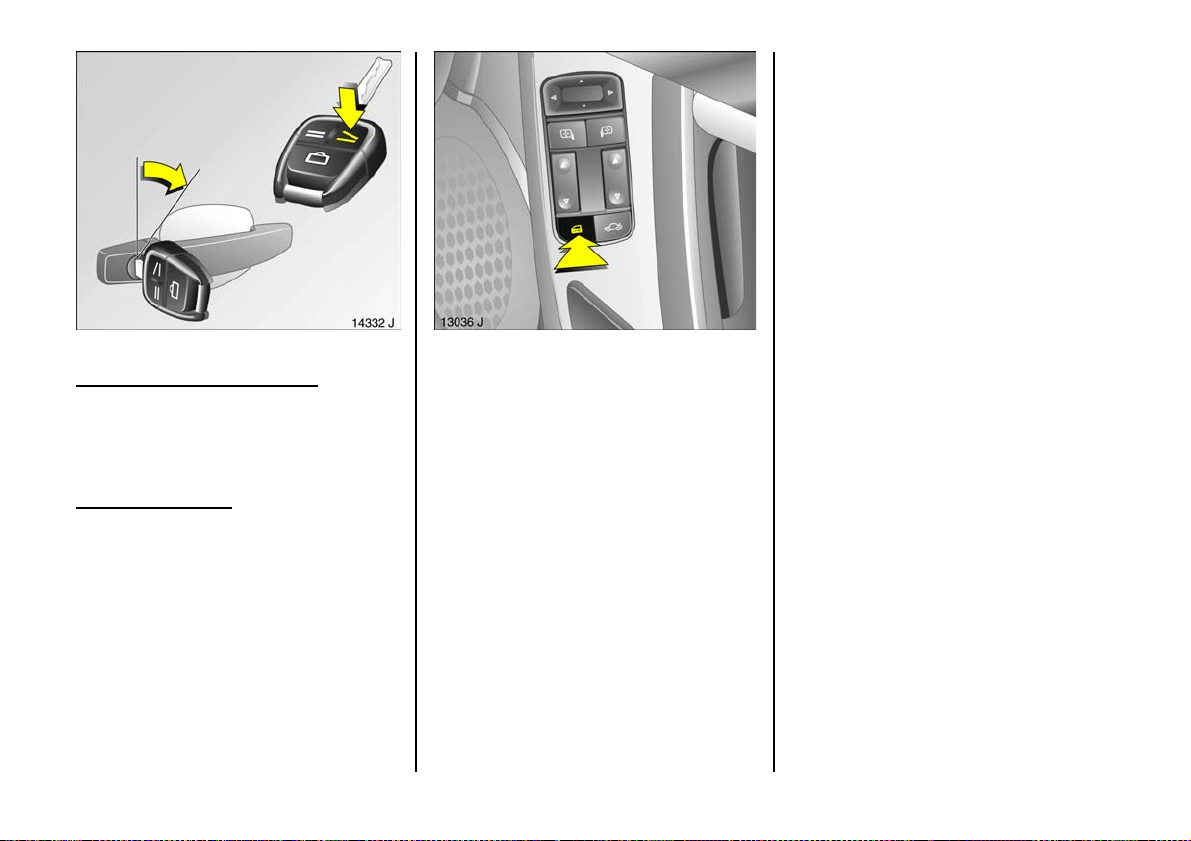
To unlock:
To unlock only the driv er’s door:
Press button q on remote control unit onc e
– or –
Turn key in driver’s door lock once towards
front of vehicle, then turn it back to the
vertical position and re move.
Unlock entire vehicle
Press button q on remote control unit
twice
– or –
Turn key in driver’s door lock towards front
of vehicle twice; then turn it bac k to the
vertical position and remove. Alternatively,
when unlocking from the inside, press
central locking switch m on one of the front
doors 3.
Cen tral l oc king sw itch for loc king
and unlocking the doors from inside
the vehicle
Pre ss bu t to n m on one of the front doors 3:
the doors are locked or unlocked as
appropriate.
When the mechanical anti-theft locking
system is active – see pag e 58, the doors
cannot b e unlocked with this button.
Not e
z If the driv er’s door is not closed properly,
the central loc king system will unlock
again immediately after locking.
z 30 seconds after unlocking using th e
radio freque nc y remote control the doors
automatically lock again if neither a
door nor the luggage compartme nt has
been opened.
z To lock the d oors from within (e.g . to
prevent und esired access from outside),
press the central locking sw itch m.
z Locked doors unlock a utoma tically if an
accident of a certain severity occurs (to
permit outside assistance) – pre requis ite:
ignition must not be switched off.
59
Page 62
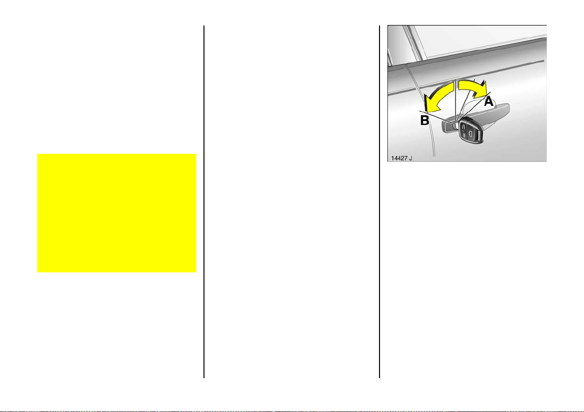
Operation of windows and sun roof 3
On vehicles w ith electronically operated
windows, the windows can be opened and
closed from outside: Hold down button q
or button p on the remote control unit, or
hold th e key in the appropriate pos ition in
the door lock, until all windows are open or
fully closed.
The sun roof can be closed from outside:
Hold button p on the remote control
de pres se d or hold th e key in th e
appropriate position in the door lock until
the sun roof is fully closed.
Care must be taken when operating the
elec tric wi n dow s an d t he s un roof. The re
is a risk of injury, especially for children,
and a danger that articles could become
trap ped.
Vehicle passengers should be informed
accordingly.
Keep a close watch on the windows and
sun roof w hen closing them. Ensure that
nothing be comes trapped in them as
th e y m ov e.
Overloa d
If the central locking system is overloaded
as a result of repeated operation at short
intervals, the pow er supply is cut off for
approx. 30 seconds.
The system is protected by a fuse in the
fusebox – see page 212.
For further inform ation on windows and
the sun roof – see pages 12 2, 124.
Malf un ctio n in cent ral lo cki ng sys te m
e.g. if vehicle battery is flat.
A = Unlock driver’s door
Turn key forward in lock p ast
resistance point as far as it w ill go.
Turn key back to vertical position and
remove.
B = Lock driver’s door
With driver’s door closed, turn key
towards rear of vehicle until it will not
move any further. Turn k ey back to
vertical position and remove.
The other doors can be opened and closed
by pulling or pushing the interior lock
button (not possible if anti-theft alarm
sys tem enable d be fore ha nd). Have caus e
of fault remedied. We recommend that you
consult a Vauxhall Authorised Repairer.
60
Page 63
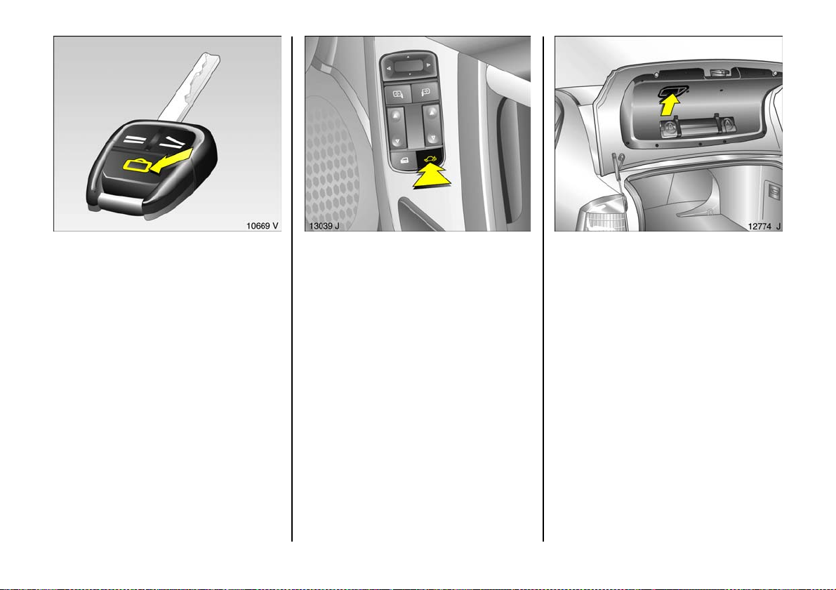
Luggage compartment
To unlock:
Press button r o n remote control
– or –
Press button q on remote control twice
– or –
Turn key in driver’s door lock forward twice ,
turn to vertical position and remove
– or –
Press button x in d river or passenger
side door 3.
The luggage compartme nt is unlocked and
can be opened within 5 minutes. On the
Saloon, this is done b y pressing the button;
on the esta te car, by pulling the button
under the handle.
If the luggage comp artm ent is open w he n
the ignition is on, s lights up in th e
tachometer display. A warning buzzer will
sound when the vehicle starts off.
If the luggage c ompartment is not ope ned
within 5 minutes, it is automatically locke d
again.
If the luggage comp artm en t is unlock ed
the number plate lights come on and
illuminate the area behind the vehicle.
If the luggage comp artm en t has be en
unlocked and ope ned, it is automatically
lock ed again 5 minutes after closing.
The luggage compartment is
automatically locked when the speed
reaches 2.5 mph (4 km/h).
There is a handle on the inside of the
luggage compa rtm en t lid or tailgate for
closing the luggage compa rtm ent.
61
Page 64
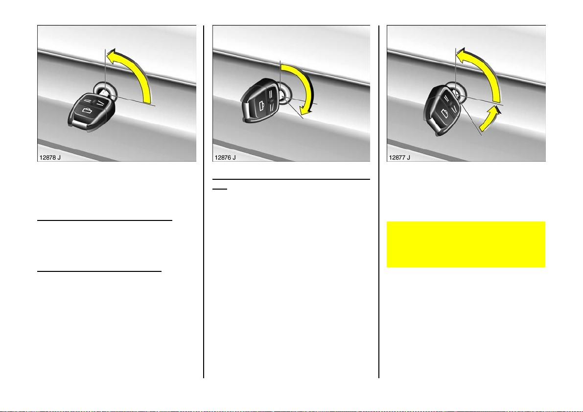
Boot lid, Saloon
The door central locking system cannot be
locked or unlocked using the lugga ge
compartment lock.
Key slot in lock in horizontal position
The lugga ge com partment ca n be lock ed
and un locked by operating the remote
control or using the key in the drive r’s s id e
lock.
Key slot in lock in v ertical position
The lugga ge com partment also remains
locked after unlocking us ing the remote
control or using the key in the drive r’s s id e
lock. This position m ust be selected if the
luggage compartment is to remain lock ed
wh en e ver this o ccu r s.
62
Locking using k ey in luggage compa rtm ent
lock
Turn key clockwise from vertical or
horizontal position as far a s it will go. To
guard against being lock ed out, the ke y
cannot the n be removed.
After the luggage compartme nt has been
closed and the k ey turned back to the
horizontal or vertical position, the luggage
compa rtm ent is locked again.
Open luggag e c ompart ment
Do not drive with the luggage
compartme nt op en or ajar, e.g. when
transporting bulky objects, since toxic
exhaust gas could penetrate the interior.
Fitting accessories to the boot lid or
tailgate will increase its weight. If it
becomes too heavy, the boot lid or tailg ate
will the n not stay open.
Page 65
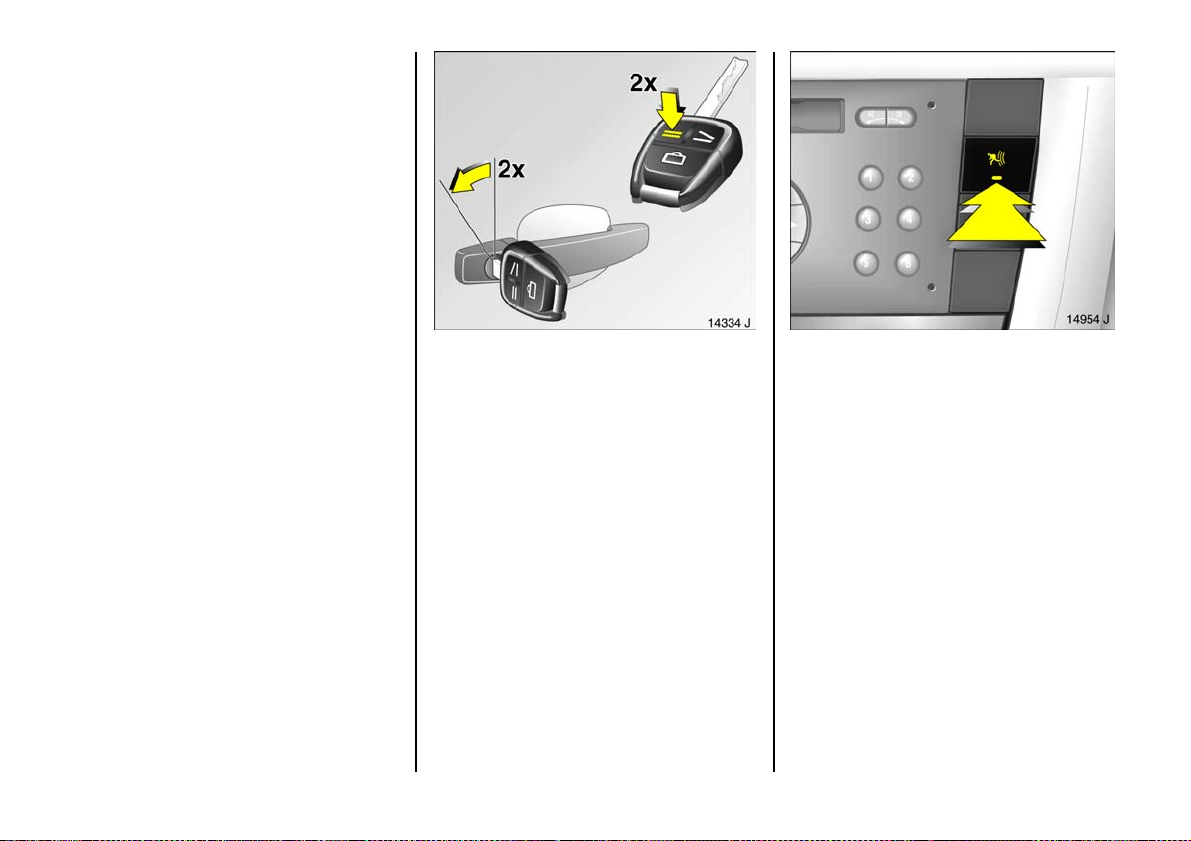
Vauxhall alarm system 3
monitors:
z the doors, luggage compartment,
bonnet,
z the passenger c ompartment,
z vehicle tilt, e.g. if it is rais ed,
z th e i g n it ion .
To activate:
All doors, windows and sun roof 3 must be
closed; press button p on th e rem ot e
control unit again within 1 0 seconds after
lock ing
– or –
Turn key in d river’s door lock toward s rear
of vehicle again within 10 seconds after
locking , then turn it back to the vertical
position and remove.
Sw itching syste m on e xcl ud ing
monitoring of the passenger
com partm ent and the v ehicl e tilt
e.g. if animals are to be le ft in the vehicle.
1. Close tailgate and b onnet.
2. Press button Ä . The LED in the b utton
flashes (maximum 10 seconds) – see
next p age.
3. Close doors.
4. Switch on anti-theft alarm system .
LE D l i gh t s up . Af t er a p p rox . 1 0 sec o nd s
the system is activated, without m onitoring of the passenger compartment or
vehicle tilt. LED flashes until system is
switched off.
6
63
Page 66
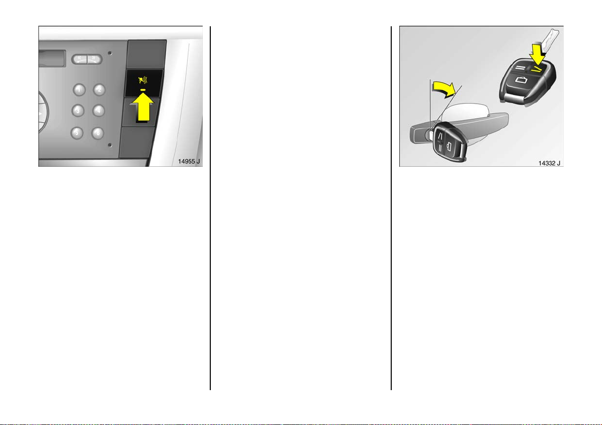
After the first 10 seconds of anti-theft
alarm system activation:
z LED flashes = System on
z LED lights up for
approx . 1 s econd = Switch-off
If a system fault occ urs, consult a
wo rk shop. We r ecom men d a Va ux ha l l
Authorised Repairer.
Light e mit ting d iode (LED)
During the first 10 seconds of anti-theft
alarm system activation:
z LED lights up = Test, switch-on
delay
z LED flashes = Door, tailgate,
bonnet open
or system fault
64
To deactivate:
Press button q on remote control
– or –
Turn k ey in driver’s door lock towards front
of vehicle, then turn it back to the vertical
position a nd remove.
Page 67
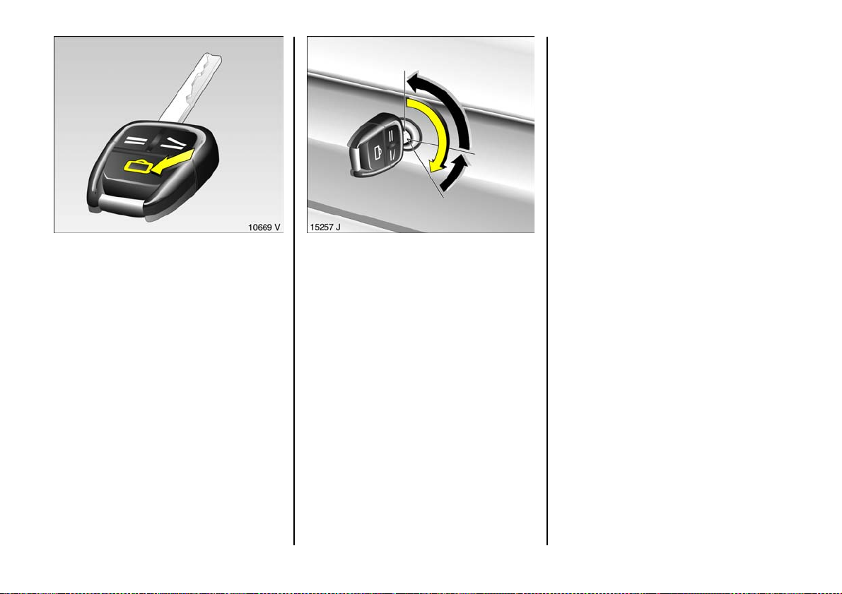
Opening and closing boot lid or tailgate
using remote control unit button r wit h
anti -theft alarm system enabled
1. Press button r on remote control,
lugga ge c ompartment is u nlocked –
see page 61, and pass enger
com partment and v ehicle tilt is dis abled.
2. Opening lugg age com partment –
see page 61 .
3. After closing the luggage compartment
the monitoring of the passenger
com partment a nd vehicle tilt is enabled
again after ap prox . 10 seconds.
Opening a nd closing the lugg age
compa rtment wit h the key in the luggag e
compa rtmen t lock 3 with anti-theft alarm
system enabled
1. Turn key clockwise as fa r as it will go:
the lugg age compartment is unlocked
and m onitoring of the passenger
compartm ent and vehicle tilt is
deactivated.
2. O pening luggage compa rtm ent –
see page 6 1.
3. C lose lug gage compartme nt.
4. Turn key back to previous position: After
approx . 10 seconds, monitoring of the
passenger compartment, luggage
compartm ent and vehicle tilt is resumed.
Alarm
On ly a certain number of a larms are
allowed to be triggered while the anti-theft
alarm system is switched on (this number is
stipula ted b y law).
The alarm take s the form of:
z an acoustic signal (horn) a nd
z a visual s ig nal (hazard warning lights).
The duration of the alarm signals is limited
due to lega l regulations.
Alarm c an be cancelled by pressing a
button on the remote control. The anti-
theft warning system is switched off at the
same time by pres sing the button q .
Alarm siren
with integrated battery
The alarm siren monitors the on-board
voltage network and triggers an ala rm if
this network is manipulated (e.g. if the
vehicle’s battery is dis connected by
unauthorised persons). The alarm siren has
its own power supply and is therefore not
dependent on the vehicles battery.
If the vehicle’s battery is to be
disconnected (e.g. for maintenance w ork),
the alarm siren must be deactivated as
follows: switch the ignition on then off,
disconnect the vehicle’s battery within 15
seconds.
To switch off alarm siren:
Switc h ignition on then off.
3
65
Page 68
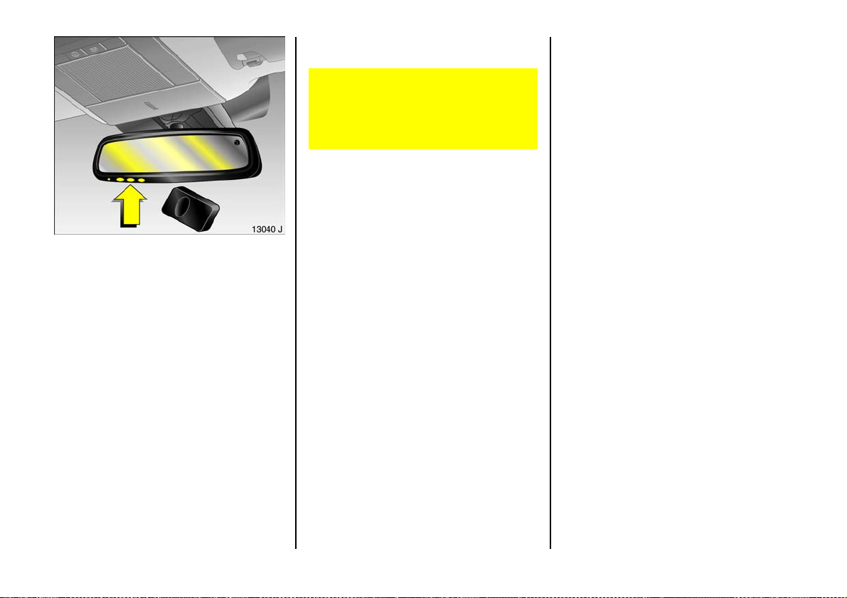
Universal radio frequency remote
control in mirror housing 3
To operate up to 3 different remotely
operated systems (e.g. garage door,
domestic alarm system, domestic exte rior
lighting).
Th e progr am med univ ersal radio
frequency rem ote control can replace the
individual remote control units of the
systems to be operated. Three buttons on
the underside of the m irror housing can be
used to operate various systems.
Consult a Vauxhall Authorised Repairer for
details on compatible systems.
Ensure that no persons, animals or
objec ts are in the movement zone of the
system to be ope rated (e.g. a ga rage
door). Vehicle passengers should be
informed of the hazards.
Basic programming of the universal
rad io control sy stem
1. Switch on ignition.
2. When programming for the first time,
press both outer buttons under the
mirror housing, until the control indicator
along side the buttons fla shes rapidly.
3. Hold the ma nual remote control u nit at a
distance of 0 to 3 0 c m fro m th e control
button area of the mirror housing.
4. Press the button on the manual remote
control unit while p ressing and holding
the desired button of the universal radio
frequency remote control.
5. The control ind icator in the mirror
housing will flash slowly at first. As soon
as it flashes rapid ly, release both
buttons. The un iversal radio control
sy st e m is n ow pr ogram m e d for the
chosen system.
6. To programme other buttons with other
sy st e ms, rep e at s teps 3 to 5 .
If a system does not operate the device
desp ite repeated programm ing and the
control indicator briefly flashes rapidly
and then shines with a steady g low for
2 seconds, the receiver may be fitted with
a variable code system – se e next page.
66
Page 69

Program ming the univ ersal radio control
system for variable code systems
1. Perform basic programming –
see previous page.
2. Activate synchronisation mode of
sys t em (se e sy ste m man u f a ctu r er ’s
system operating m anual) and briefly
pres s the pre-p rogr am med button on
the univ ersal radio freq uency remote
control three times within 30 seconds.
3. The radio control system is now
pr og ra mmed f o r va r iab l e c o de s y s t e m s.
To programme other systems for
variable codes, re peat the above
procedure for the other buttons of the
unive rsal ra dio control system.
Using the univ ersal radio cont rol system
With the ignition on, press the required
universal radio control button, and the
control indicator in the mirror housing will
illuminate. The pre-program med system
can now be operated using the universal
radio control system.
Reprogramming individual button
se tt i ng s
If a button that has already been
programme d is to be used for a different
system, simply repeat steps 3 to 5 of the
basic programming procedure described
previously.
Erasing all prog ramm ed button settin gs
Before selling the vehicle, it is a good idea
to erase button settings.
Button settings can only be e rased as a
unit. It is not possible to erase individual
button settings. Buttons can, how ever, be
indiv idually reprogram med
(se e "Reprogramm ing individual bu tton
settings").
In order to erase the programming of all
3 buttons, press both outer buttons and
relea se as soon as the LED begins to flash
(a fter approx. 2 0 seconds). All button
settings hav e now be en cleared and can be
programme d anew at any time.
Not e
Retain the ma nual remote control in case
reprogramming is require d. It is also
possible to continue using the manual
remote control.
If a fter repeated ly performing the above
steps a system fails to respond to the
universal rad io control, consult a workshop.
We recommend that you consult a
Vauxhall Authorised Repairer.
During programm ing, the vehicle should be
within the range of the receiver. Under no
circumstances should the vehicle be in the
mov ement zone of a system (e.g. garag e
door).
Do not programme systems which do not
have an automatic safe ty stop
(manufactured before 1982).
Take note of the system ma nufacturer’s
safety instructions for drives a nd manual
remote control units.
67
Page 70
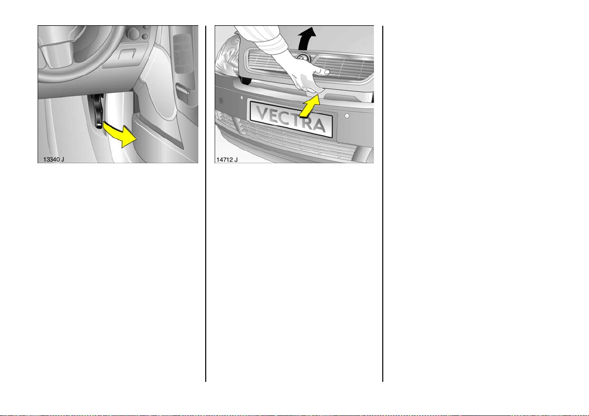
The b onnet is held open automatically. To
close the bonnet, lowe r it s lowly and allow
it to fall into the lock under its own we ight.
Check that the bonnet is locked in position
by pulling at its front edge . If it is not
engaged, repeat the procedure.
Bonnet
To open the bonnet, pull the outer release
lever / locate d below the instrumen t
panel on the driver’s side. The bonnet will
then be unlocked and will partially open.
Return the relea se lever to its original
position.
68
There is a safety catch on the underside of
the bonnet: lift this upwards and open the
bonnet.
When the bonnet is opened, snow or dirt on
the bonn et can slide down and obstruct th e
air intake. Air intake – see page 142.
Page 71
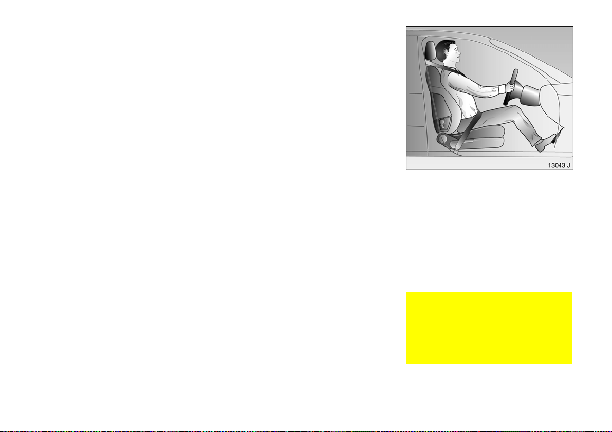
Seats, Interior
Adjusting the front s eats
see page 5.
Electrically adjustable front seats 3
see page 79.
Increasing luggage compartment
size by folding down the front seats
see page 82.
Seat pos ition
Adjust driver’s sea t such that with the
driver s itting upright the steering wheel is
held in the area of its upper spokes with the
driver’s arms s lightly bent.
Push p ass enger seat as far b ack as
possible.
The seat backrests must not be tilted too
far ba ck (recommended tilting angle
app rox. 25°).
Imp ortant: Do not sit nearer than 10
inches (25cm) from the steering wheel, to
permit safe airbag d eployment.
Disregard can lead to injuries which
could be fatal. Vehicle passe ngers
should be informed ac cordingly.
69
Page 72
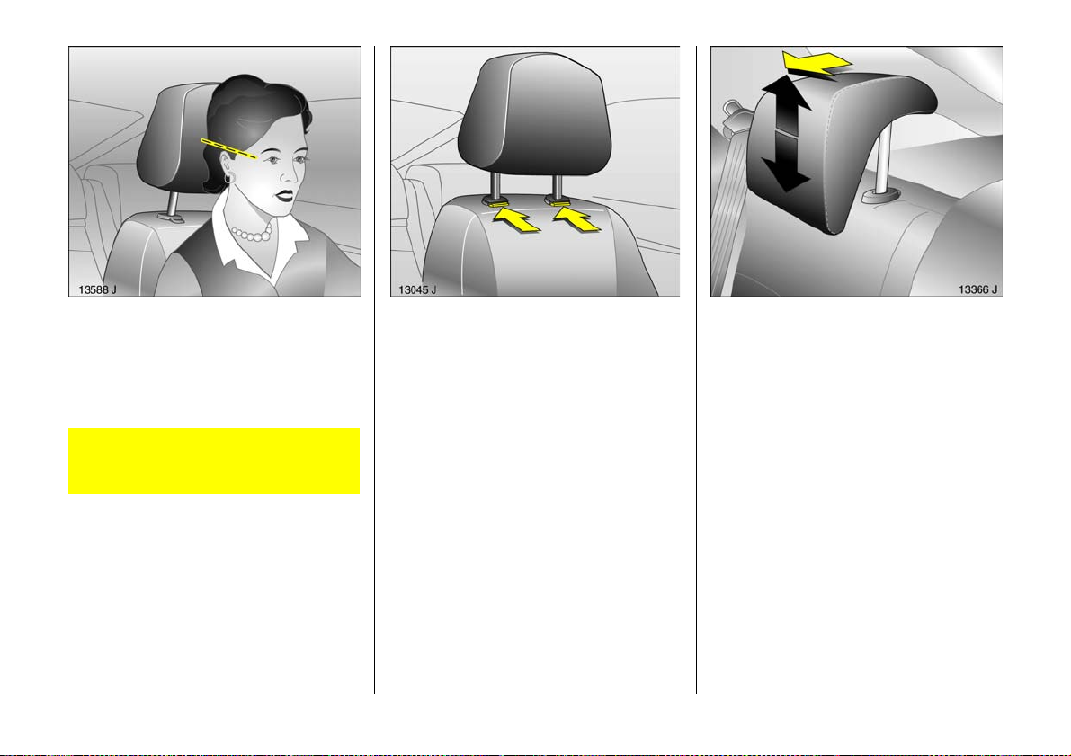
Head restraint position
The midd le of the head restraint should be
at eye level. If this is not possible for
extremely tall persons, set to highest
position, and set to lowest position for
small pe rsons.
Disregard can le ad to injuries which
could be fatal. Vehicle passengers
should be informed accordingly.
Setting – see page 7 and right hand column.
70
He ad res tr ai nt s
To remove head restraints: Release the two
springs by pressing them and d etach the
head restraint.
Setting – see page 7.
To enlarge the luggage compa rtm ent,
push the hea d restra int all the w ay down –
see page 7.
Rear head restraints, integrated in
t he re ar s e at b ac kre s t 3
To adjust them, pull the head restraint
forwards with both hands and at the same
time adjust the height.
The head restraints can be moved to the
lowest pos ition to improve visibility where
seats are unoccupied.
Page 73
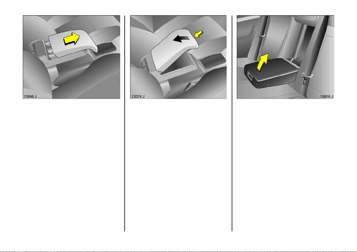
Armrest 3 between the front seats
Th e arm res t can be pushed forw ard. If the
armrest is not require d, push it back and
fold it up.
To op en , sli de the armre st back, p ress the
button on the front and open.
Rear seat armrest
Th e arm rest can be folded dow n .
If the rear centre se at is being used or the
rear sea t backrests are b eing folded down,
fold armrest up ward.
To open, press the button on the front and
open.
The maximum permitted load on the
stowage compartment is 0.5 kg.
71
Page 74
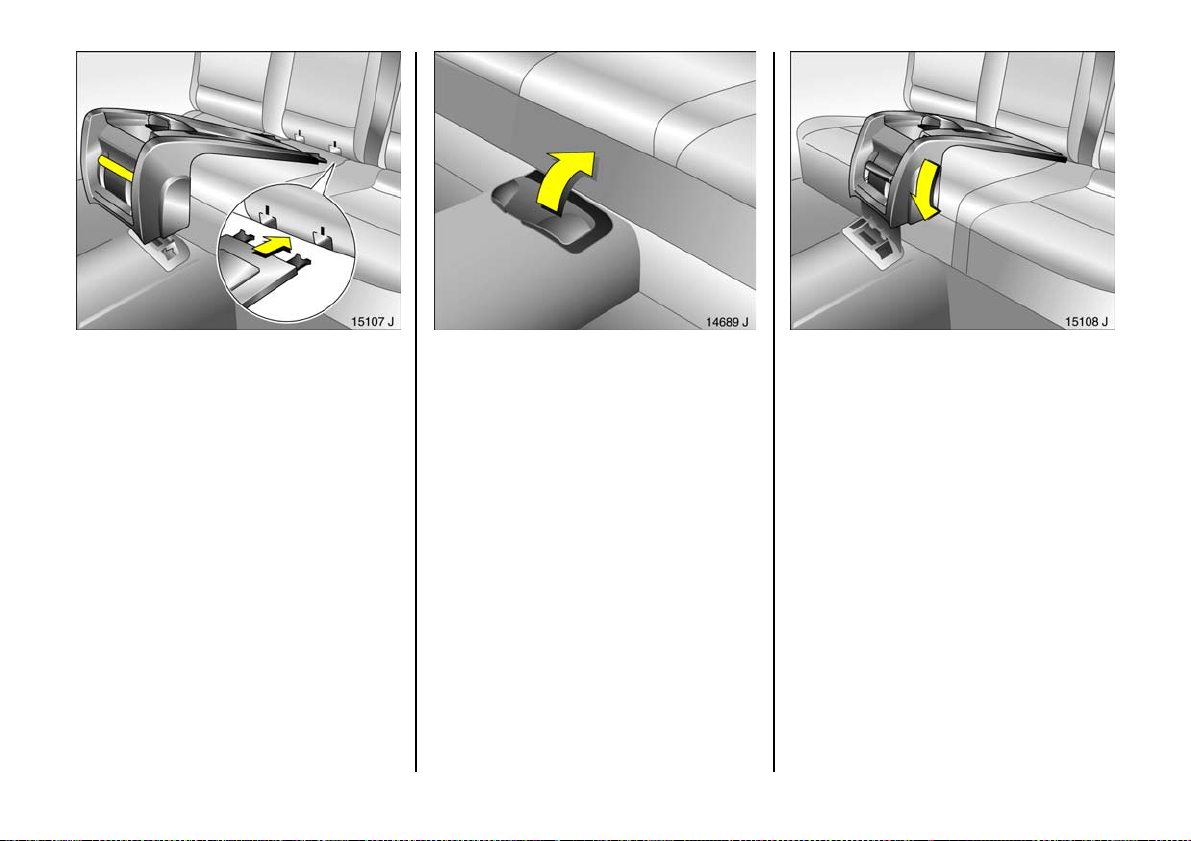
Travel Assistant 3
Instal ling the Travel Assistant
Insert the two rear push-in sleeves into the
marked recesses in the backrest and
engage.
72
Swivel open and hold cover of front
attachment points in floor in front of
console.
Swivel conne cting console d ownw ard and
engage in attachment points.
Page 75
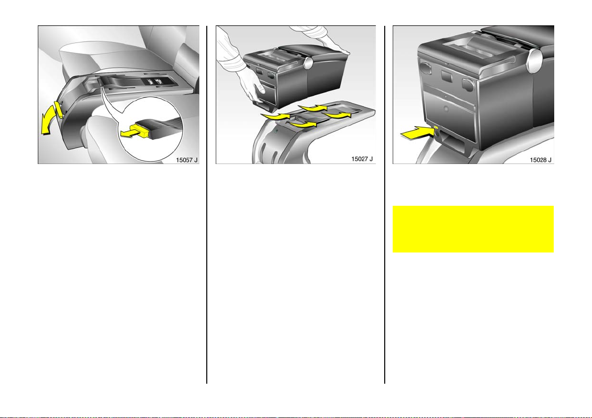
Swivel the locking lever downwards. Check the locking p osition of the Travel
Assistant: the red mark (see Fig. 15028 J)
must not be visible. Otherw ise, lock using
the key – see page 77, Fig. 15037 J.
To lock, insert Tra vel Assistant into recesses
in connecting console and slide back as far
as possible.
If it is correctly locked, the red mark must
no longer be visible in the window,
ot h er wis e t h e pro ce dure mu s t be repe ated .
If it is not correctly locked, the Travel
Assistant could b e propelled forward
with considerable force wh en hard
braking occurs, risk of injury.
6
73
Page 76
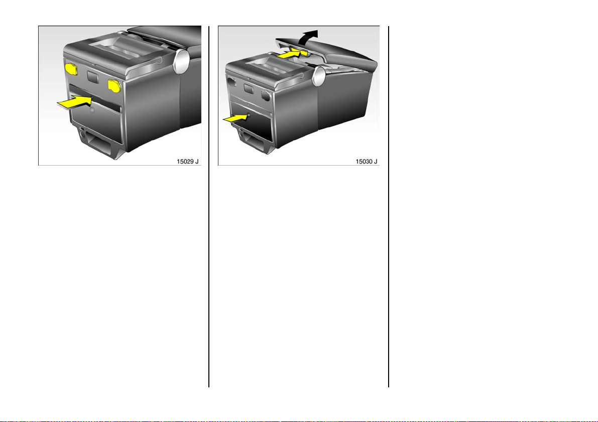
The upper stowage compartment is
located under the armrest. To open, press
the button and fold the armrest upwards.
Drink holder and ac ces sory sockets
O pen th e drink h o ld er by press ing the
marking.
Only accessories with max imum power
consumption of 120 Watts must be
conn ected to the accessory sockets. For
notes – see page 89.
74
Stowage compartments
Ope n the lo we r sto w ag e com par tmen t by
pres sin g the ma rk in g. The un de rside of t h e
compartment has an opening through
whic h the objects in the compartment can
be raise d.
Page 77
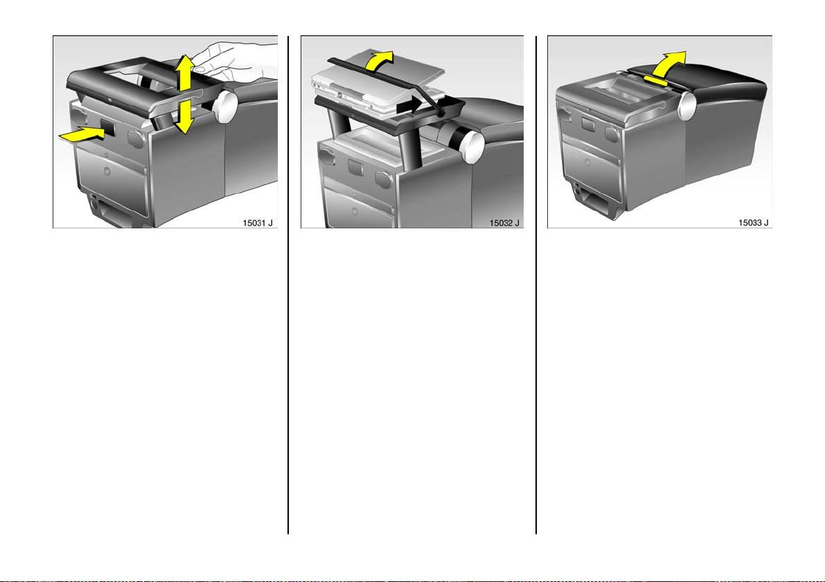
Connecting console for DVD player 3
Pull connecting console upward, press
button and slide downward .
Swivel up th e display holder, slide DVD
player display into bracket from below and
fix in position with bracket.
Maximum load: 1 kg.
Electric cool box
To open, fold open the armrest together
with the stowage compa rtm ent.
75
Page 78
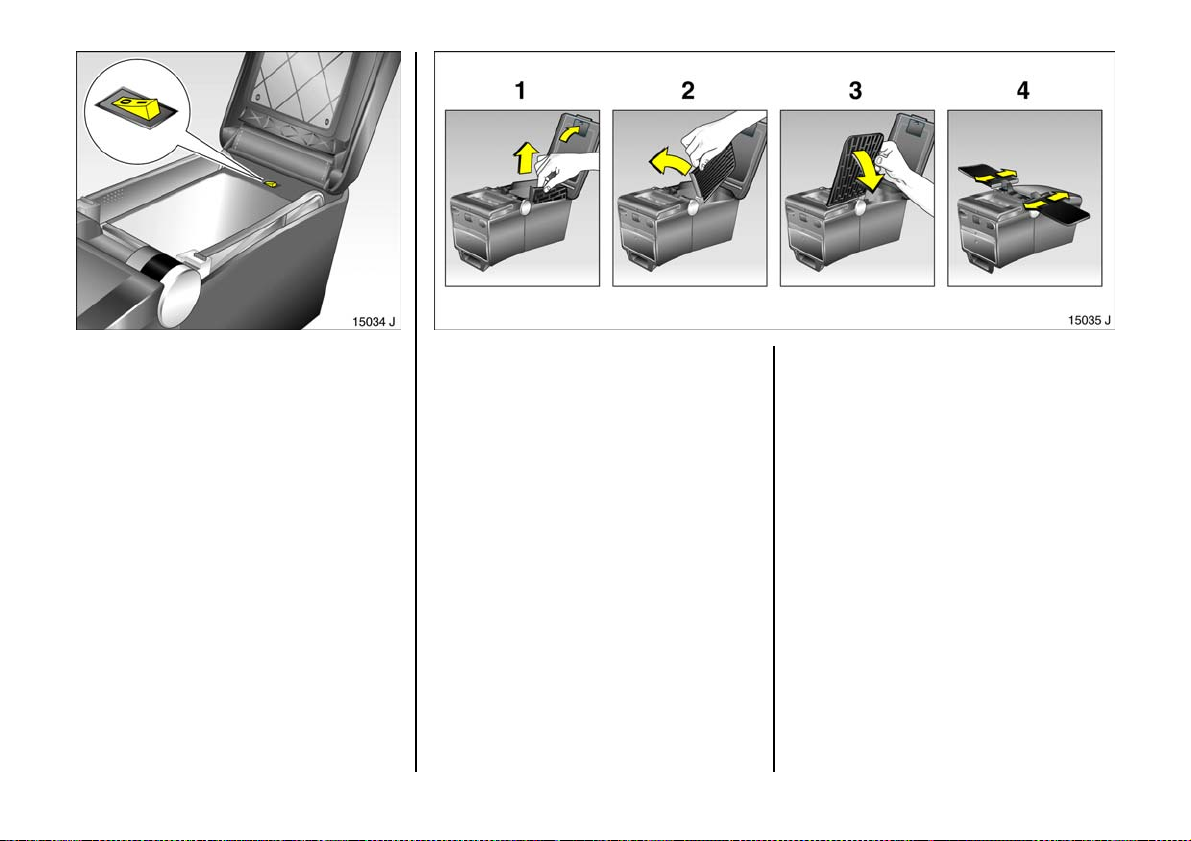
Switch on the cool box as needed.
76
Ta b le s
Fold arm res t u pwar d (1).
Use recessed grip to p ull tab le upward as
fa r as it will go (1 ), swivel table forw ard (2)
and fold downward (3 ).
Set required clearance by adjusting
longitudinal position of table (4).
Page 79
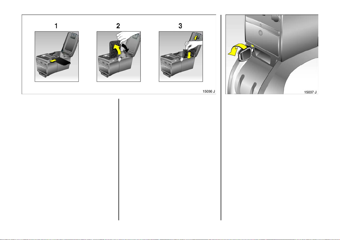
To fold away the table, swivel the
armrest up.
Push the table forward as far as it will go (1).
Fold the table upwards past the resistance
point (2), swivel it downwards and insert in
the Travel Assistant (3).
Swivel armrest down.
Removing the Travel Assistant
Open catch using key, red mark appears in
window.
6
77
Page 80
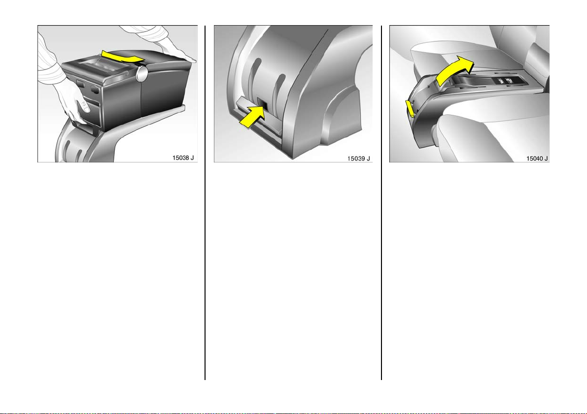
Pull the Travel Assistant to the front on the
connecting console and remove.
F it the p r ot ec tiv e c o v er 3 on the plug.
78
Press the locking lever down, press the
button on the front of the connecting
console and sw iv el the locking lever
up wards.
Swivel connecting console upward and pull
out of recesses.
Page 81
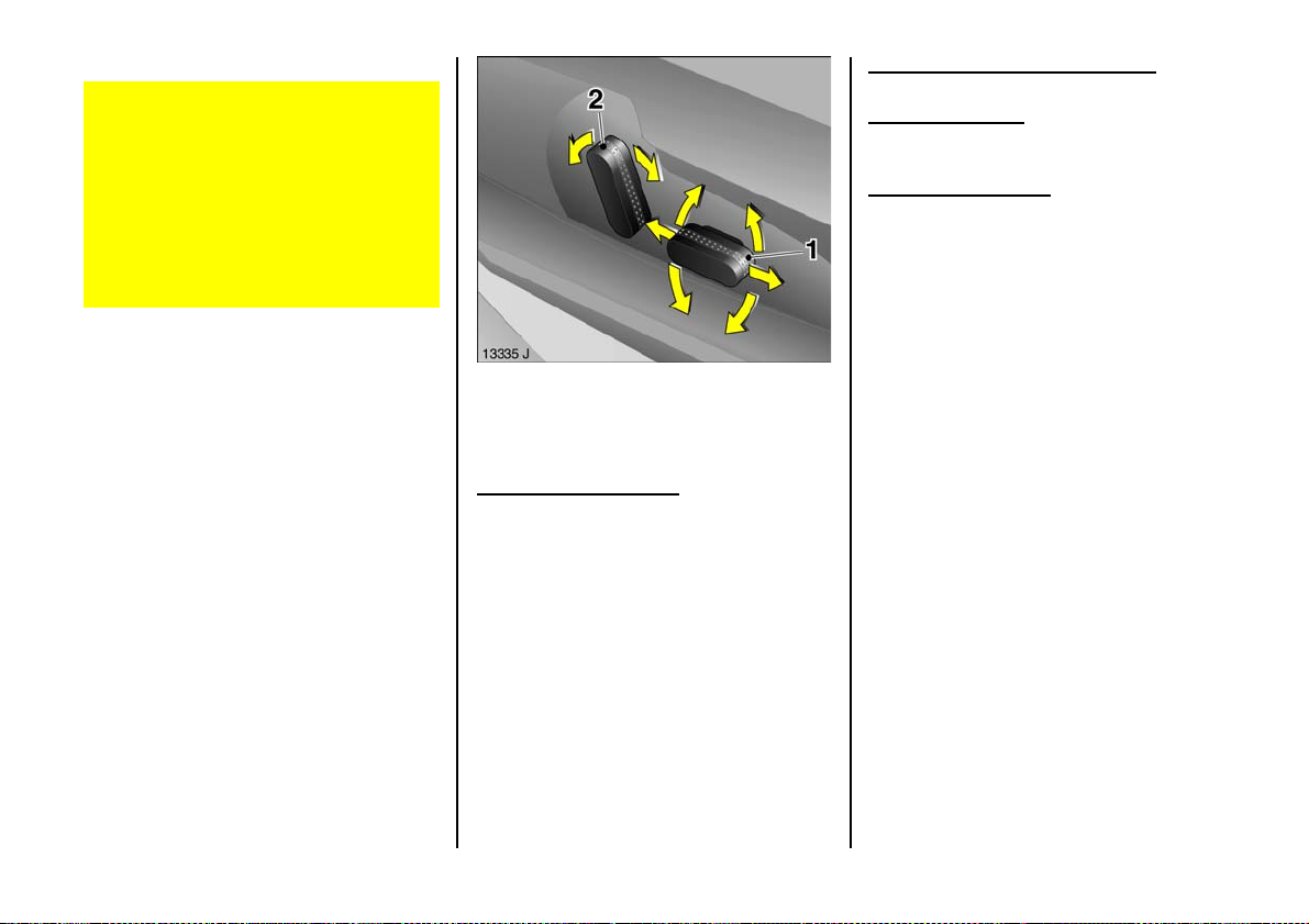
Electrically adjustable front seats 3
Care must be taken when operating the
elec trically adjustable sea ts. The re is a
risk of injury, particularly for children ,
and a danger that articles could become
trap ped.
Keep a close watch on the seats when
adjusting them.
Vehicle passengers should be informed
accordingly.
Adjusting the longitudinal p osition
Move switch 1 forwards / backwards.
Height adjustment
Move switch 1 upwards / downwards at
rear.
Seat back adjustment
Turn sw itch 2 forwards / backwards.
Operate switch unt il desired s eat po sition is
reached. Se at position – see page 69.
After a djusting the se at, adjust height of
seat belt – see page 98.
Adjustment
The seat position can be adjusted by
means of switches on the outboard side of
the seats.
Ad justing the inclination
Move switch 1 upwards / downwards at
fr on t .
79
Page 82
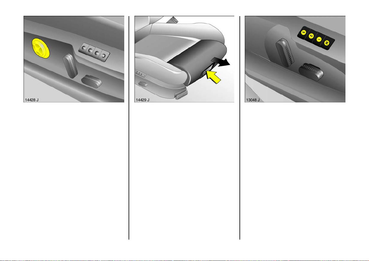
Electrical ly ope rat ed lumba r sup port 3
on driver’s seat
Adjust lumb ar support u sing four-way
switch on outboard side of driver’s seat.
Adjust lumb ar su pport to suit pe rsonal
requirements.
Moving support up and down: push b utton
up or down.
Increasing and decreasing support: push
button forward or backwa rd.
80
Thi gh sup port 3 on driver’s seat
To adjust, lift handle at front and slide seat
padding.
Do not adjust the thigh support whilst
driving.
Memory function 3 for electrical ly
ad justable dri ve r’s seat, exte rior mirrors
and interior mi rror
Three different s eat and mirror settings can
be stored (e.g. for three drivers).
Page 83

Readin ess for ope ration
z With ignition on,
z Within 10 m inutes of switching ignition
off,
z Within 10 minutes of opening or closing
the driver’s door,
z Within 10 m inutes of inserting or
removing the ignition key.
Readin ess for operation stops when the
vehic le is locked.
Storing settings
1. Adju st se at ,
2. Adjust inte rior mirror – s ee page 8,
3. Adjust exterior mirror – s ee page 8,
4. Press m emory button M and the position
button to be used (1 , 2 or 3)
simulta neously, and s torage is
acknowledged by an acoustic signal.
Retriev ing settings
Keep posit io n key 1, 2 or 3 pressed until the
sto red s ea t an d mir r o r p o si t io n s h ave b ee n
re a ch e d .
For reasons of safety, seat adjustm ent
stops immediately if the position button is
released or one of the setting buttons is
op er at e d.
Ad justme nts may only be performed with
vehicle stationary.
Store and activate the setting s using the
remote controls
W h en the veh icle is loc ked wit h the radio
frequency remote c ontrol, the current
positions of the driver’s seat, the exterior
mirrors and the interior mirror are stored.
Personal settings stored using different
radio frequency remote controls can be
retrieved as follows: open driver’s door
within one minute of unlocking a nd the
positions stored using the radio frequency
remote control are automatically set.
The seat adjus ting proc edure can be
stopped immediately if required by
operating a s etting button.
Passeng er mirror w ith par king a id
see page 8 .
Overload
If the seat setting is electrically overloaded,
the power supply is automatically cut off
for a short time.
Th e syste m is p r o t ec t e d by a f u se in t h e
fusebox – see page 212.
81
Page 84
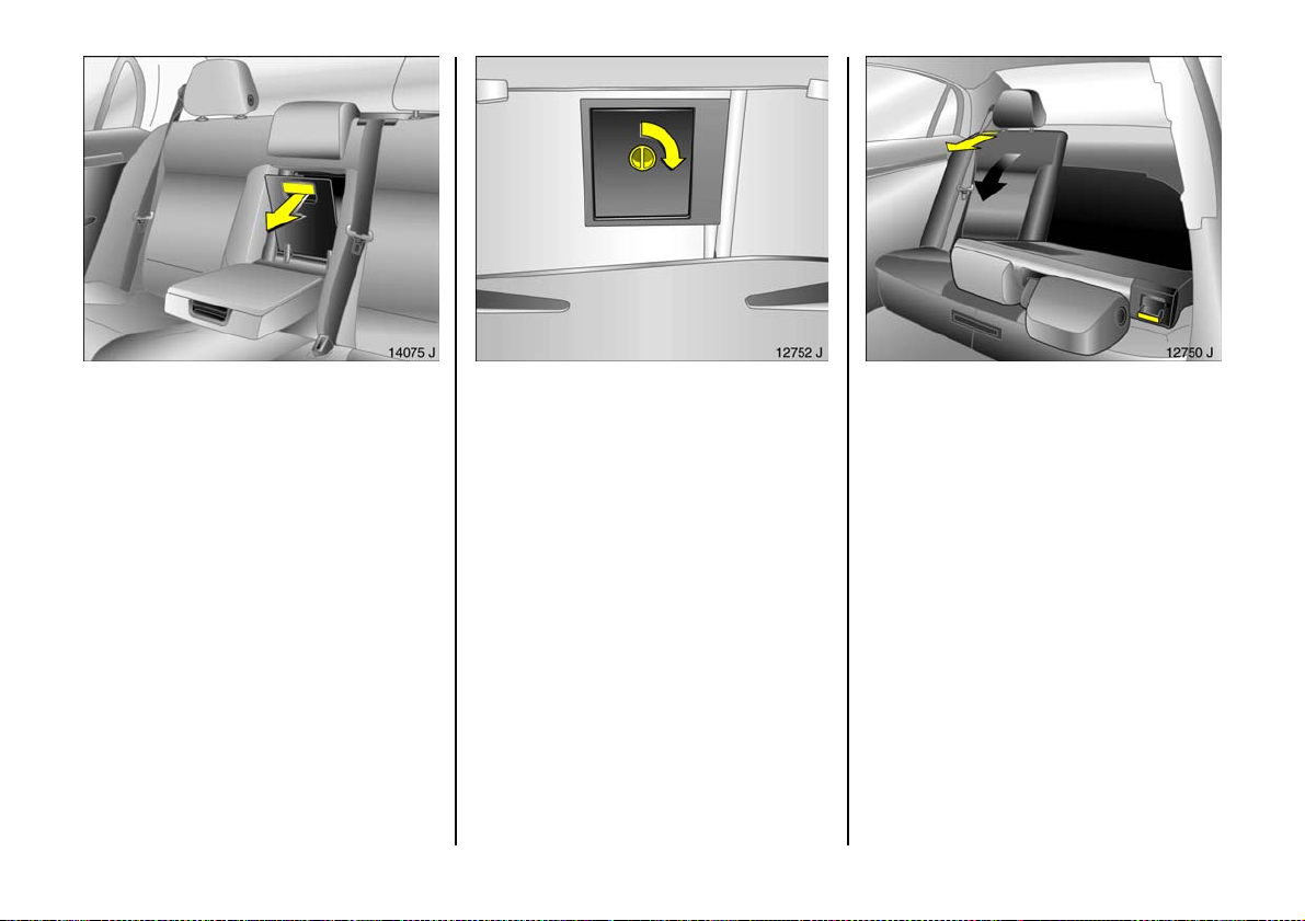
Luggage compartment extension
Fold dow n the cover behind the arm re st
Fold down the arm rest on to the seat
cushion, pull the han dle and tilt the cover
forwards.
The outer seats can continue to be used for
passengers.
Engage the cover behind the centre
armrest audibly in position.
82
Cover behind armrest can be locked from
lugg age compartme nt 3: turn handle 90°:
Locked = Handle horizontal
Unlocked = Handle vertical
Folding d own the rear s eat ba ckrests
Push the rear head restraints right down.
Place the belt buckles in storage pockets in
the seat cushions.
Push front s eats forwards a little.
Remove Travel Assistant 3 – see page 77.
Unlock one or both rear sea t backre sts by
depressing pushbuttons and fold down on
to seat cushion.
Return the air front seats to the desired
positions.
Page 85
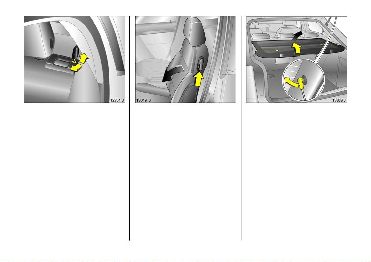
When returning rear seat backrests to
upright, they should audibly click into
position.
The three-point seat belt for the centre rear
seat can only be pulled out of the retractor
if the rear seat backrests are properly
locked into position.
On some versions, the rear seat backrests
can be locke d 3 : insert the key in the lock
next to the pushbutton, turn 180° and
remove – see figure.
Folding down the front passenger seat 3
Pus h head restraint on front pas senger’s
seat down as far as it will g o.
Slide back the front passenger seat.
Fold front passenger seat forward by
ra ising release lever.
When returning front passenger seat
backrest to upright, it should audibly c lic k
into position.
Note s on loading
see page 88.
Luggage compartment cover 3,
5-door Saloon (Hatch)
To remove, unhook the retaining straps
from the tailgate.
Re move th e cove r from the side guide s.
Fit in reverse order.
83
Page 86
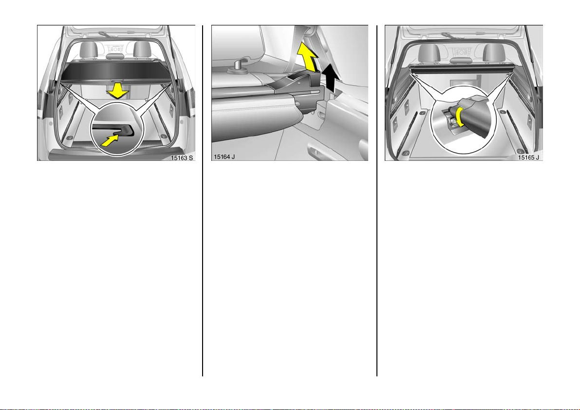
Luggage compartment cover 3,
Estate
To close:
Pull lug gage compartment cover toward s
rear of vehicle using handle and hook into
side retainers.
Do not place any heavy or sharp-edged
objects on the cover.
To open:
Remove luggage compartment cover from
side brackets. It rolls up automatically.
84
Removing
Open luggage compartme nt cover.
Move release lever on right side of lug gage
compartment cover upward . Lift right
cover a nd remove from brac kets.
Fit tin g
Fit the lug gage compartment cover in the
bracket on the left-hand side, fold up the
release lever on the right-ha nd side, fit the
lugg age compartme nt cover in the bracket
on the right-hand side and p ress the
relea se lev er closed.
Safety net 3,
Estate
The safety net can be fitted behind the rear
seats or, with the rear seat backrest folded
down, behind the front seats.
Fitti ng behind the rear seats
Remove the luggage comp artm ent cover.
Fit the cassette with rolled safety net into
the side brack ets and enga ge b y twisting.
Page 87
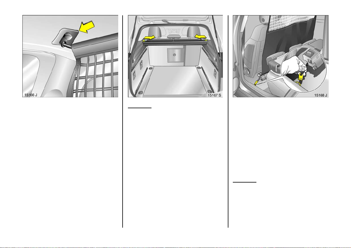
Extend the net from the cassette. The roof
frame houses two fitting openings. Fit the
net rod in the fitting opening on one side
and then the other and engage by pushing
forward.
Fit the luggage compa rtm en t cove r.
Removing
Remove the lug gage compartment cover.
Detach the safety net rod from the
brackets in the roof frame.
Slide both latches inwards; push the
cassette with rolled net rearwards in the
br a ck e t, tw is t a n d r em ov e u pw a rd s.
Fitti ng behind front se ats
Fold both rear seat back rests. Place the
rolled net on the floor behind the front
seats in such a way that the cog rail in the
slit on the net is to the rear.
Pull ea ch side hook from the cassette and
attach it to an eye 3 in the vehicle floor.
Extend the net from the cassette. The roof
frame houses two fitting openings. Fit the
net rod in the fitting opening on one side
and then the othe r and engage by pushing
forward.
Removing
Detach the safety net rod from the
brackets in the roof frame.
Un do the side hooks fro m the e yes 3 in the
vehicle floor.
85
Page 88
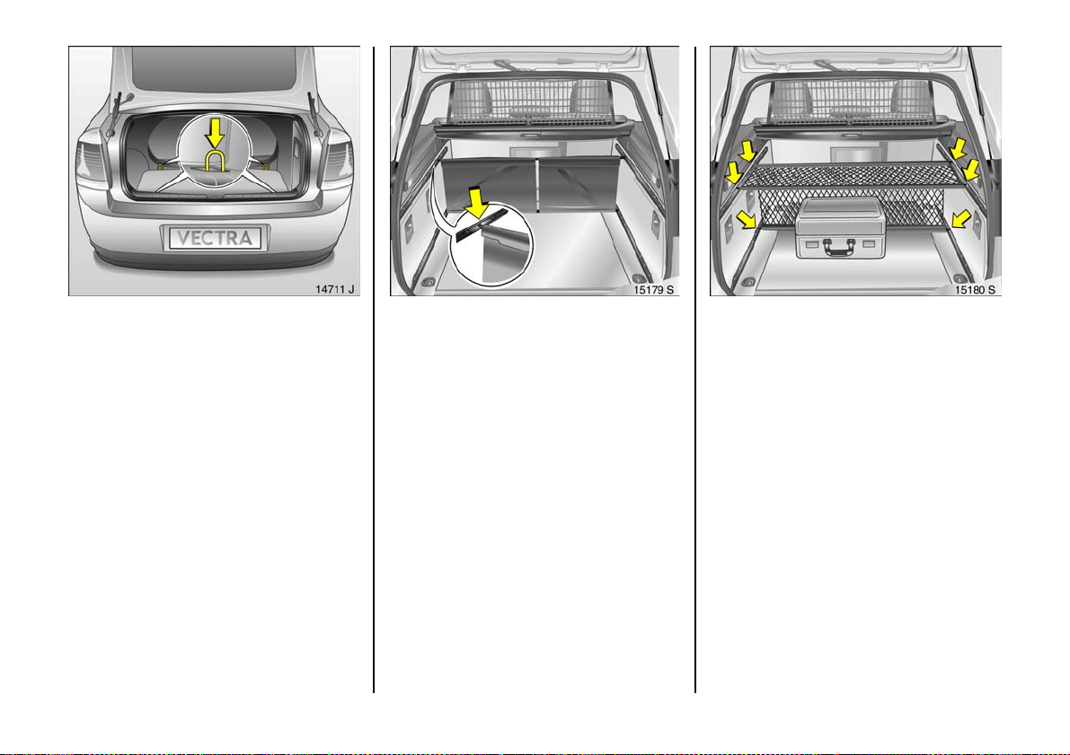
Lash ing eyes
Th es e ena ble load s to be secu re d in
position in the lugga ge compartme nt using
lashing straps 3 or a luggage net 3 .
86
FlexO rganizer 3
Flexible system for dividing the luggage
compartme nt or se curing load s in an
Estate.
The components are housed in a stowage
compartment at the rear in the load floor –
see page 92.
The system consists of
z variab le partition net
z variab le partition wall
z partition rod
z me sh p ockets for t h e s i de walls
z hooks
The components can be mounted in the
two guide rails in the side walls of the
lugg age compartme nt.
The figures show examples of possible
uses.
Varia ble part ition wa ll
Fig. 15179 J. Press the rod s of the partition
wall together slightly and e ngage in the
desired guide rail openings in the side
walls. The rods can be engaged in various
positions.
Varia ble part ition net
Fig. 15180 J. Press the rod s of the partition
net together slightly and e ngage in the
desired guide rail openings in the side
walls. The rods can be engaged in various
positions. The partition net can be
mounted vertically or horizontally at
different levels.
Page 89
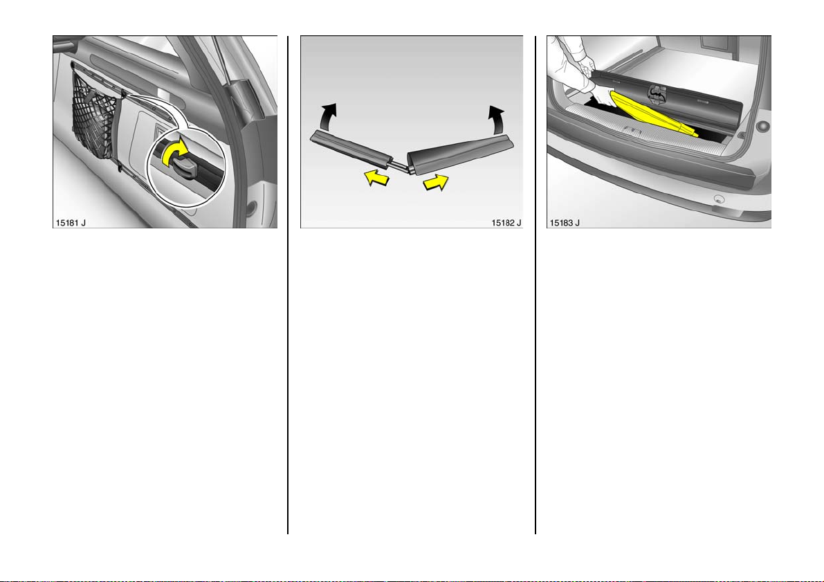
Hooks and mesh pockets for the side walls
Fig. 15181 J. Engage the hooks in the
openings of the guide rails in the side walls
as indicated in the figure and turn 90°. The
mesh pockets can be hung from the hooks.
Removing
Press together the rods of the partition
wall / n et o r the telesco pic ro ds and r emove
from the guide rails. Turn the hooks 90°
and rem ove.
Fle x Orga nize r s to wa ge
FlexOrganizer components are housed in a
stowage compartm ent at the rear in the
loa d floor. To open, raise the handle and
op en the flap – see page 92, Fig. 15171 J.
To stow, pull apa rt the partition wall / net
rods as well as the sepa rate teles copic rod
in the middle and fold them in half. Roll the
partition wa ll and net together and place it
in the compartment with the other
components. Close the cover.
87
Page 90
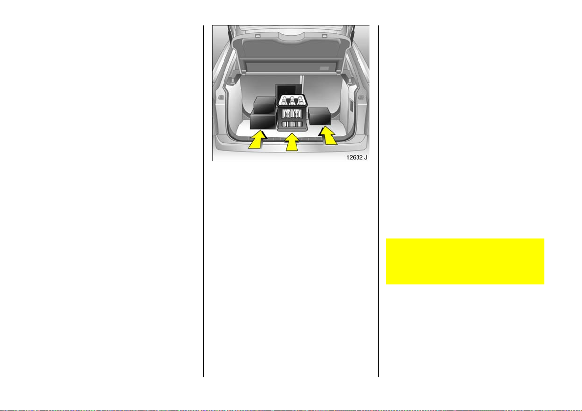
Notes on loading the vehicle
z Heavy objec ts in the luggage
com partment should be placed as far
forward as pos sible aga in st th e engag ed
rear seat backre sts or, if the rear seat
backrests are folded down, against the
front seat backrests. If objects are to be
stacked, the heavier objects should be
placed at the bottom. Unsecured objects
in the luggage compartme nt would be
thrown forward with great force in the
event of heavy braking, for e xam ple.
z Secure heavy objec ts with lashing
straps 3 attached to las hin g eyes –
see page 86 . If heavy loads slip when the
vehicle is braked h eavily or driven
around a bend, the handling of the
vehicle may change.
z Saloon: loose objects in the luggage
com partment should be secured against
slipping using a luggage net 3 –
see page 86 .
z Estate: when transporting objects in the
luggage compartment, fit a safety ne t 3
– see page 84, or FlexOrganizer 3 –
see page 86 .
z Estate: close the luggage compa rtm ent
cover so there is no reflection in the rear
wind ow.
z If objects are being tran sporte d in the
luggage compa rtm ent, the rear sea t
backrests must be locked in position –
see page 8 2.
z Do not a llow the load to protrude above
the upp er edge of the rear seat
backrests, or above the upper edge of
the front seat backrests if the rear seat
backrests are folded down.
z The warning triangle 3 and first-aid kit 3
must alway s b e free ly a cces sib le .
z Do not place any objects in front of the
rear window or on the instrum ent panel.
They are reflected in the glass, obstruct
the driver’s view and will be thrown
through the vehicle, for instance in the
event of heavy braking.
z Obje c ts m ust n ot be sto r e d in th e a i rb ag
inflation area, because they could cause
injury if the airbag inflates.
z Do not drive with the luggage
compartme nt op en, e .g. when
transporting bulky objects, since toxic
exhaust gas could penetrate the interior.
z Weights, payload and roof loa d –
see page 262 .
z Driv ing with a roof load – see pages 158,
161, 188, increases the sensitivity of the
vehicle to cross-winds and has a
detrimenta l effect on vehicle handling
owing to the vehicle’s higher centre of
gravity.
Disregarding the instructions can
potentially lead to fatal injury. Vehicle
pa s seng ers sh ou ld be in f or m ed
accordingly.
88
Page 91
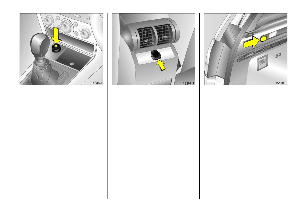
Cigarette lighter ) 3
In front centre console.
Press in cigarette lighter with ignition
switched on. Switches off automatically
once the element is glowing. Pull out
lighter.
Accessory socket 3
The soc ket i n the centr e con sole and t h e
cigarette lighter socket can be used to
connect electrical acce ssories. The socke ts
are ready for operation when the ignition is
switched on. If the eng ine is not running the
battery will be discharged. An a dditional
accessory socket 3 can be found in the
centre console b eneath the rear air vents
and in the Travel Assistant 3.
Estates have an additional accessory
socket to th e left in the luggag e
compartme nt next to the luggage
compartment lig hting.
Do not dam age the soc kets by using
unsuitable plugs.
The maximum power consumption of
electrical ac cessories must not exceed
120 w atts.
Do not connect any current-delivering
acc essories, e.g. electrical charging
devices or batteries .
Electrical ac cessories connected to the
socket must c om ply with the ele ct ro-
ma gnetic compa tib ility requirem ents laid
down in DIN VDE 40 839, otherwise vehicle
malfunctions m ay occur.
A cces so ry so cket s in th e T rav el A s sista n t 3 –
see page 74.
89
Page 92
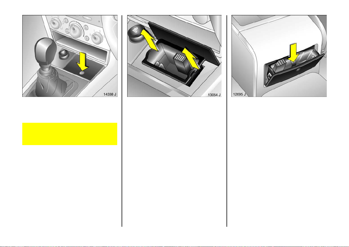
Ashtray
To be used only for ash and not for
combus tible rubbish.
Disregard can lead to injuries which may
be f atal. Vehicle p a ssen ge r s s h o u ld be
informed accordingly.
Ashtray, front
The cover opens when pressed at the point
indicated .
90
To empty, grip both sides of the ashtray
insert and pull u pwards.
Rear a shtray 3
In the rear centre console.
The cover opens when pressed at the point
indicate d.
To e mpty: open t h e ashtra y, pres s the
spring (arrow) and pull out the ashtray.
Page 93
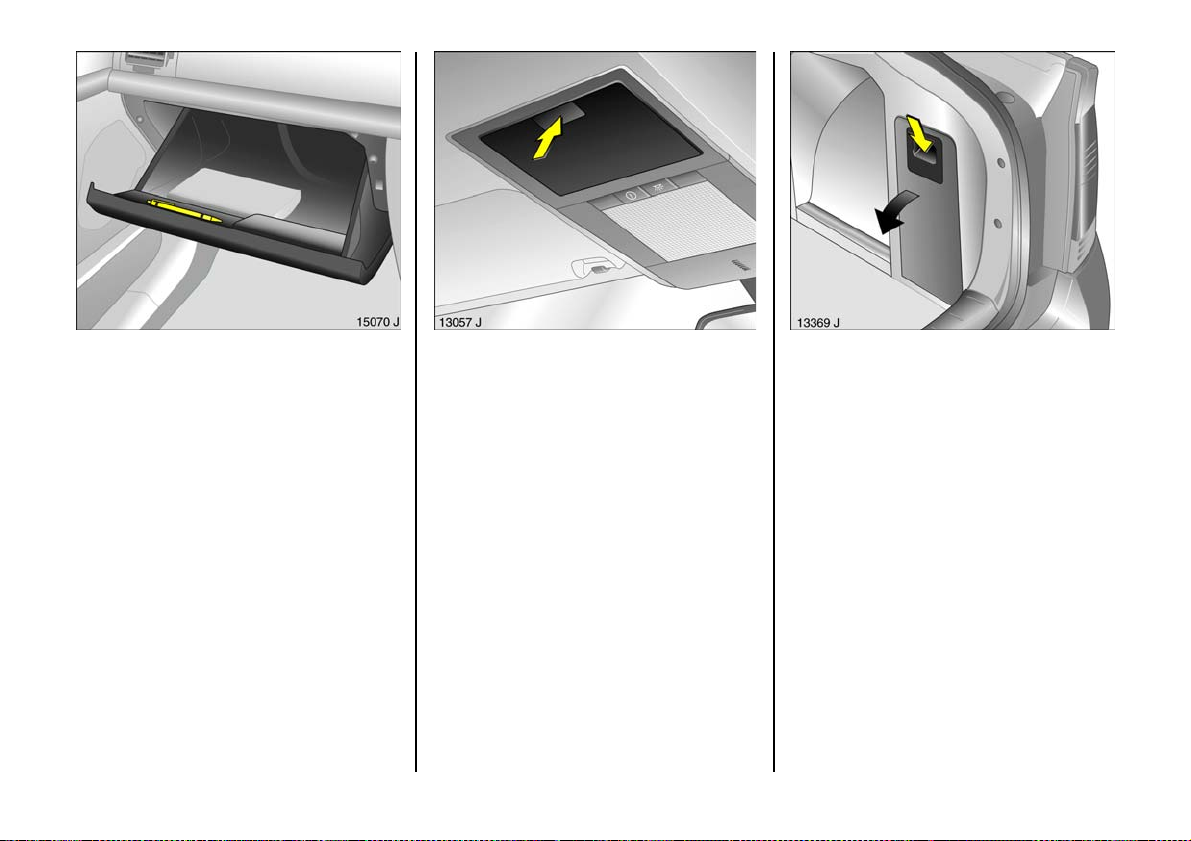
Glove c om partm ent
To open, pull handle upwards.
At the front of the opened cover there is
a p en h o lder .
Cooled glove compartment 3 –
see page 139.
Stowage compartmen t in the roof
linin g 3
To open, press the point indicated.
The max imum permitted load on the
stowage compa rtment is 0.4 kg.
The stowage compartme nt m ust be closed
whilst driving.
Stowage compartments in the
luggage compartment
To acc ess press d own bar an d ope n the
cover.
Warn ing triangle ¨ 3 and first-aid kit + 3
stowage – see page 2 04.
Stowing the spare wheel – see page 205.
Jack and vehicle tools stowage –
see page 208.
6
91
Page 94
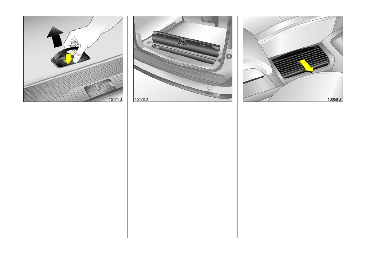
Estates have an additional stowage
compartme nt in the luggage com partment
floor.
To open, pu ll the re lease lever and ope n
the flap.
92
When opening, ensure that the flap opens
at the seam so that the entire floor cover is
not r a i s ed .
Drink holders, front 3
The drink holders can be found between
the front seats in the centre c onsole: slide
cover ope n.
Page 95
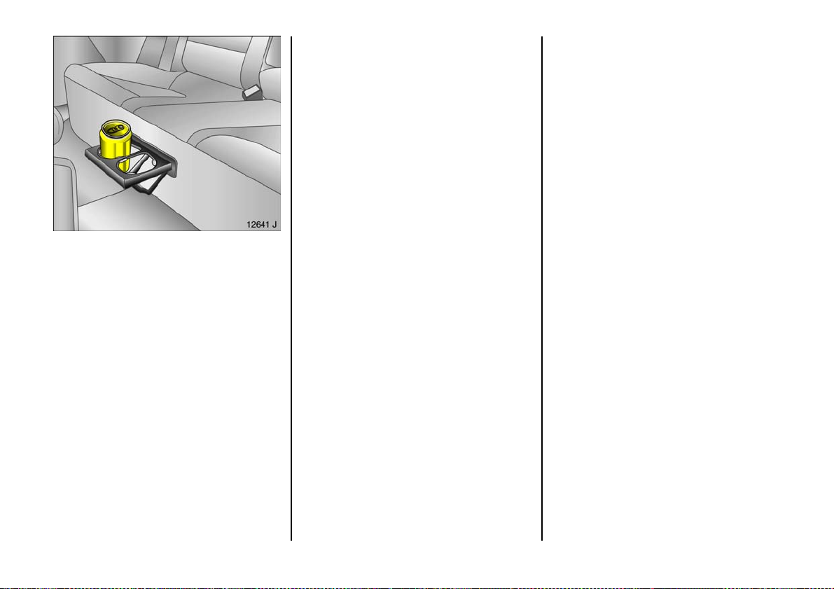
Drinks holders, rear 3
The drinks holder can be found beneath
the centre seat: pressing front edge moves
drink holder out.
Su n vis o rs
Use the sun visor to protect from glare by
pulling it down and swivelling it to the side.
93
Page 96

Safety systems
Three-stage re straint system
Compris ing:
z three-point seat be lts,
z be lt tensioners at the front seats and the
rear outer seats,
z a irbag sy ste m s f or driver , fro n t
passenger and outer rear seats 3.
The three stag es are a ctivated in sequence
depending on the seriousness of the
accident:
z The automatic seat be lt locking de vices
prevent the belt strap from being pulled
out and thus ensure that the vehicle
occupants are retained in their seats .
z The front seat b elt buckles and outer
rear seats are pulled downwards. As a
result, the seat belts are instantaneously
tightene d and the occupants are mad e
aware of the deceleration of the vehicle
at a very ea rly sta g e. This re duc es the
stress placed on the body.
z The airbag systems a re also triggered in
th e ev en t of s eri ou s ac cid e nt s an d f o rm a
safety cushion for the occupants.
Depending on the severity of the
accident, the front a irbags inflate in two
stages.
The airbag systems serve to suppleme nt
the three-point seat belts and belt
ten sione rs. The seat belt s must t h erefo r e
always be worn. Disregard of the se
instructions may lea d to injuries or
en dan g e r li fe. Ve hi cl e p ass en ge r s sho u ld
be informed accordingly.
Be sure to read the a ccompanying
desc ription of the child restraint system!
94
Page 97
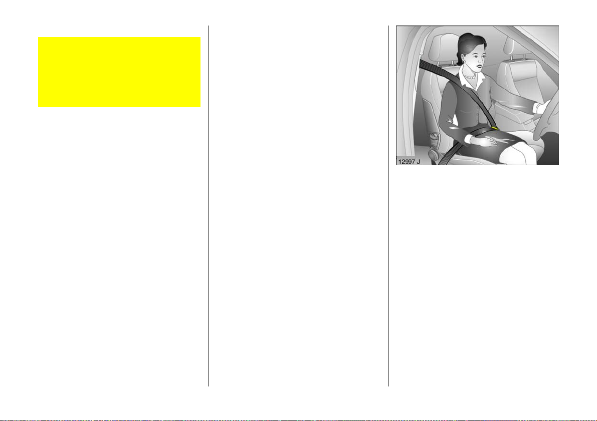
Seat belts
Alwa ys wear your seat be lt, and th at
means also in urban traffic and when
you are a rear seat pas senger. It can
save your life!
Pregnant women must always wear a
seat belt – see page 98.
In the e vent of an accident, persons not
wearing sea t belts e ndanger their fe llow
oc cup ants and themselves.
Warning light X for the seat belt – see
page 35.
Seat belts are designed to be used by only
one person at a time. The y are not suitable
for a ny one under 12 years of age or
15 0 cm.
For children up to 12 years of age we
recommend the Vaux hall child restraint
system – see page 110.
Three-point seat belts
The vehicle is equipped with three-point
seat belts with automatic re tractors and
locking d evices, allowing freedom of body
mov ement although the spring-tensioned
belts always ens ure a snug fit. For seat
position – see pages 69, 99.
The belt has a "vehicle s ensitive retra ctor"
which is de signed to lock during heavy
acceleration or deceleration in any
direction.
95
Page 98
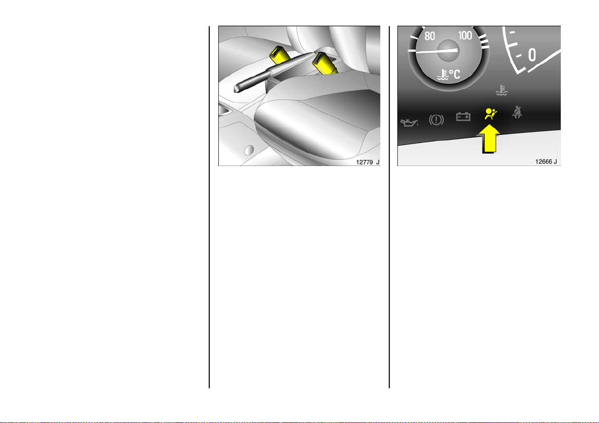
Belt tens io ners
The front seat belt and outer rear seat
systems are equipped with b elt tensioners.
If a head-on or tail-end collision of a
certain severity occurs, the belt buckles are
pulled downwar d and the sh oulde r and lap
belts are tightene d in an instant.
96
Actuati on of be lt te nsioners
is indicated by illumination of control
indica tor v, see next p age.
The be lt te nsioners must be replace d after
activation. We recommend that you
consult a Vauxhall Authorised Repairer.
If the seat belts are undamage d the
op erat ion th e reof is unaf fe ct ed, eve n if the
belt tensioners have been triggered.
Further inform ation – see page 9 9.
C ont rol indic ator v for belt tensioners
The belt tensioners are monitored
electronically together with the airb ag
systems and the ir operational rea diness is
indicate d on the instrument panel by
control indicator v . When the ignition is
switched on, the c ontrol indicator lights up
for approx. 4 seconds. If it does not light
up, does not go off after 4 seconds, or
lights up while driving, there is fault in the
be l t t e ns io n er sy st e m o r t he a i rb a g s y s te m s
– see page 105. The belt tensioners or
airbag systems may fail to trigger in the
event of an a ccident.
Page 99

Have the cause of the fault remedied.
We recom mend that y ou consult a
Vauxhall Authorised Rep airer.
The system’s integrated self-diagnostics
allows faults to be quickly remedied. have
Car Pass on hand when consulting a
Vauxhall Authorised Repairer.
The c ontrol indicators can also be locate d
in the tac home ter d ispl ay dia l – se e
page 37.
Imp or tant
z Accessories and other objects must not
be affixed or placed within the action
zone of the belt tensioners as this may
result in injury if the belt tensioners are
triggered.
z Do not mak e any modifications to the
components of the belt tensioners, as
this will render the vehicle unroad-
worthy.
Imprope r han dling (e.g. removal or
installation) can activ ate the belt
tensioners – risk of injury.
z The belt tensioner and airbag system
control electronics can be found in the
centre console area. In order to avoid
malfunctions, do not store magnetic
objects in this area.
z We recommend that you have the front
seats removed by a Vauxhall Authorised
Repairer.
z The belt tensioners only actuate once.
Please replace belt tensioners that have
been triggered. We recom mend that you
consult a Vauxhall Authorised Repairer.
z Applicable safety directives must always
be ob served when di s posin g of the
vehicle. For this reason, disposal should
be performed by an authorised recycling
company. We recommend that you
consult a Vauxhall Authorised Repairer.
97
Page 100
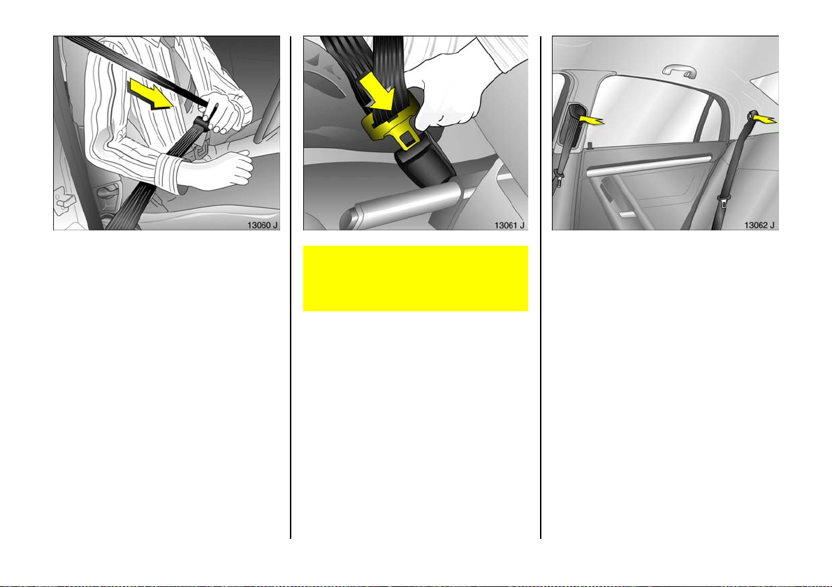
Usin g t he b elts
Fitting seat belts
Pull the belt out of the retractor and guide
it across the body, making ce rtain that it is
not twisted.
Insert the la tch plate into the buckle. The
front sea t backrest must not be tilted back
to o f ar o r the se at b elt will n ot op erate
properly. The recommended angle of
inclination is 25°. Mak e sure that the lap
belt is not twisted and that it fits snugly
across the body. Tension the be lt
frequently while d riving by tugging the
diagonal part of the belt.
98
On pregnant women in particular, the
lap belt must be positioned as low as
possible across the pelvis so as not to put
too much pressure on the abdomen.
Bulky clothing prevents the belt from fitting
properly. The belt must not rest against
ha rd or fragile obje cts in the pockets of
you r clothing (e.g. ballpoint pens, ke ys ,
spectacles) be cause these could cause
injury. Do not place any objec ts (e.g.
ha ndbags, mobile phones) between the
belt and your body.
Height adjustment
of seat belt upper anchorage p oint:
1. Pull belt out slig htly.
2. Front seat belts: Press button down or
slide belt guide up.
Rear seat belts: Press be lt guide an d
slide it upwards or downwards.
3. Se t des ired height.
4. Allow anchorage to lock aud ibly into
position.
Do not adjust height while driving.
 Loading...