

Page 1

OPEL Meriva
Owner’s Manual
Page 2

Back to overview
Page 3

OPEL Meriva
Back to overview
Operation, Safety, Maintenance
Page 4

Data specific to your vehicle
Back to overview
Please enter your vehicle’s data here so that it is readily accessible. Please refer to the sections "Servicing and maintenance" and "Technical
data" and the identification plate.
Fuel
Designation
Engine oil
Grade
Viscosity
Tyre pressure
Tyre size Front
Summer tyres
Winter tyres
Rear
Weights
Gross vehicle weight rating
– EC kerb weight
=Loading
Page 5
Introduction
Back to overview
Your vehicle is an intelligent combination
of forward-looking technology, impressive
safety, environmental friendliness and
economy.
It now lies with you to drive your vehicle
safely and to see it performs perfectly. This
Owner’s Manual provides you with all the
necessary information to that end.
Make sure your passengers are aware of
the possible risk of accident and injury
which may result from improper use of the
vehicle.
You must always comply with the specific
laws of the country that you are in. These
laws may differ from the information in this
Owner’s Manual.
When this Manual refers to a workshop visit, we recommend your Opel Service Partner.
All Opel Service Partners provide first-class
service at reasonable prices. Experienced
mechanics trained by Opel work according
to specific Opel instructions.
The Owner’s Manual, infotainment system
instructions and the vehicle Service and
Warranty Booklet should always be kept
ready to hand in the vehicle glove compartment.
Make use of the Owner’s Manual
z The "In Brief" section will give you an ini-
tial overview.
z The table of contents at the beginning of
the owner’s manual and within the individual chapters will show you where everything is.
z Its index will help you find what you
want.
z Yellow arrows in the illustrations serve as
points of reference or indicate some action to be performed.
z Black arrows in the illustrations indicate
a reaction or a second action to be performed.
z This Owner’s Manual depicts left-hand
drive vehicles. Right-hand drive vehicles
are operated in the same way.
z The Owner’s Manual uses the internal
engine codes. The corresponding sales
designations are found in the chapter
"Technical data".
z Directional data, e.g. left or right, or
front or back, in the descriptions always
relate to the direction of travel.
Symbols
6 Continue reading on next page.
3 signifies equipment not fitted to all vehi-
cles (model variants, engine options, models specific to one country, optional equipment, Genuine Opel Parts and Accessories).
Page references are indicated with 3. 3
means "see page".
Danger, 9 Warning, Caution
9
9 Danger
Text marked 9 Danger provides infor-
mation on risk of endangering life. Failure to comply with the instructions could
endanger life.
9 Warning
Text marked 9 Warning provides information on risk of accident or injury. Failure to comply with the instructions could
lead to injury.
Caution
Text marked Caution provides information on possible damage to the vehicle
Failure to comply with the instructions
could lead to vehicle damage.
Safe driving!
Adam Opel GmbH
Page 6

Back to overview
Page 7

Contents
Back to overview
In Brief ....................................................... 2
Keys, doors, windows,
slide and tilt sunroof .......................... 26
Seats, Interior .......................................... 44
Instruments, Controls ............................. 82
Lighting ................................................. 102
Infotainment system ........................... 111
Climate control ..................................... 114
Driving and operation ......................... 129
Self-help, vehicle care .......................... 165
Service and maintenance ................... 199
Technical Data .................................... 218
Index ...................................................... 234
Page 8
2In Brief
Back to overview
In Brief
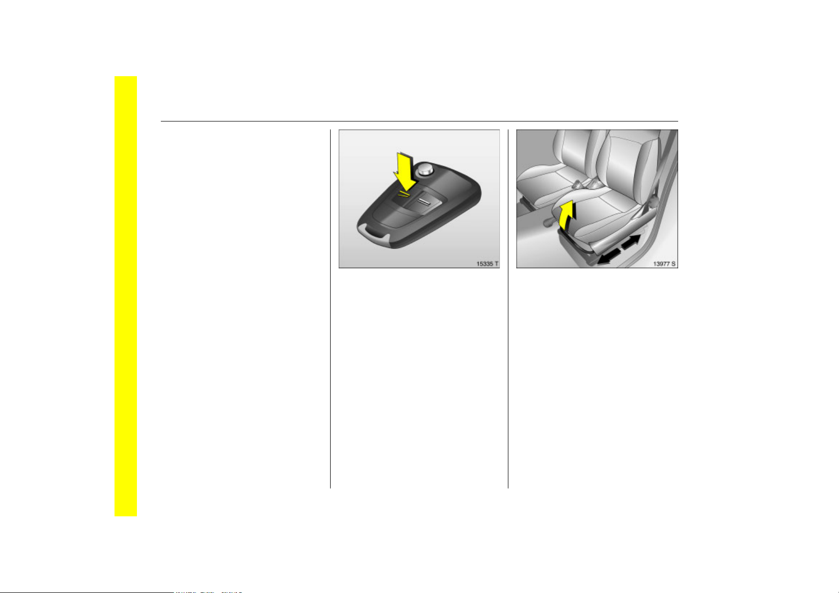
Picture no: 15335T.tif
To unlock the vehicle: Press
button q
Open the door by pulling on the door
handle. To open the tailgate, pull on the
button in the handle recess and pull the
tailgate upwards.
Door locks 3 26, key 3 26, remote control
3 28, central locking system 3 30, antitheft locking system 3 3 31, tailgate 3 32,
anti-theft alarm system 3 3 34.
Picture no: 13977s.tif
To adjust front seat leg room: Pull
handle, slide seat, release handle
Seats 3 44, Seat position 3 45.
Page 9
3In Brief
Back to overview
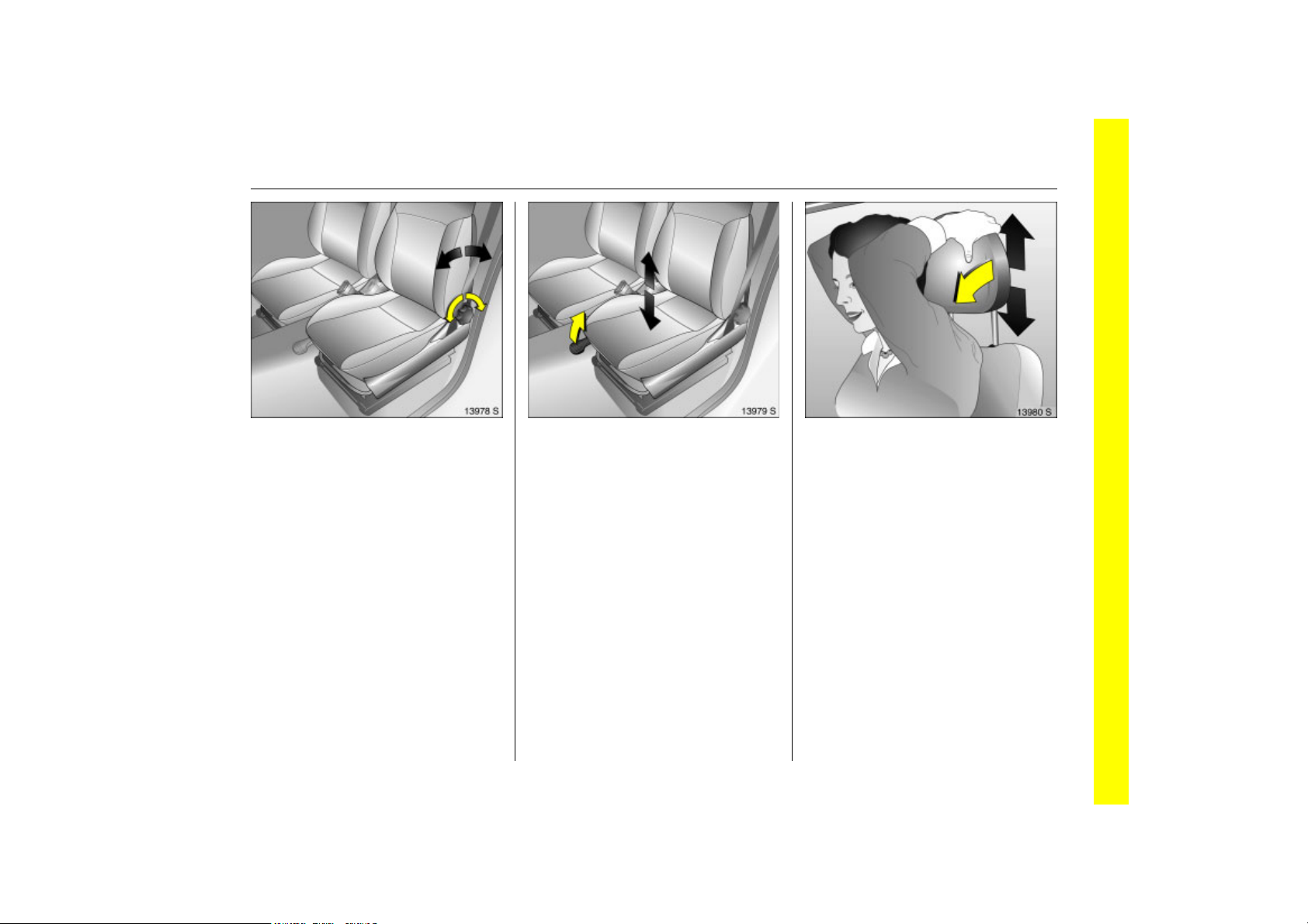
Picture no: 13978s.tif
To adjust front seat backrests:
Turn handwheel
Do not lean on seat backrest whilst
adjusting it.
Seats 3 44, Seat position 3 45.
Picture no: 13979s.tif
To adjust front seat height 3: Pull
lever
Lift lever and relieve some weight from seat
to raise it or press down on seat with body
weight to lower it.
Seats 3 44, Seat position 3 45.
Picture no: 13980s.tif
Head restraint height of front and
rear outer seats: Tip head
restraint forward to release, hold
and adjust height, engage
Head restraints 3 46, Centre rear head
restraint 3 47, Head restraint position 3 47,
Head restraint removal 3 48.
Page 10
4In Brief
Back to overview
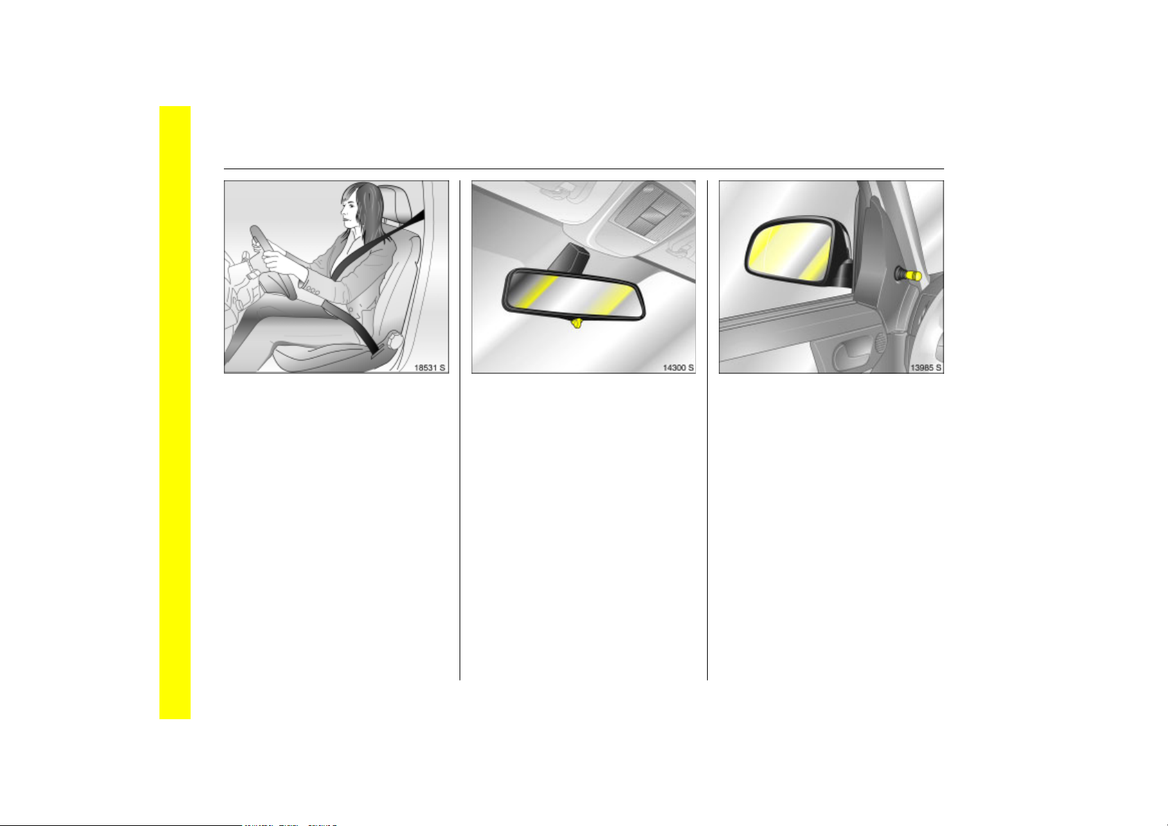
Picture no: 18531s.tif
Extend the seat belt and clip it
into the buckle
The seat belt must not be twisted and must
lie snugly against the body. The backrest
must not be tilted back too far (maximum
approx. 25).
To release belt, press red button on belt
buckle.
Three-point seat belt 3 59,
Airbag system 3 3 67, seat position 3 45.
Picture no: 14300s.tif
To adjust interior mirror by
swivelling
Swivel lever 3 on underside of mirror
housing to reduce dazzle.
Interior mirror 3 38, Automatic anti-dazzle
interior mirror 3 3 39.
Picture no: 13985s.tif
Use the knob to move the exterior
mirrors in the appropriate
direction
Mirror 3 36, Aspherical exterior mirrors 3
3 37, Swinging in exterior mirror 3 37.
Page 11

5In Brief
Back to overview
Picture no: 16099s.tif
Adjust exterior mirrors
electrically 3
Select the mirror to be adjusted using the
rocker switch and adjust using the fourway switch.
Mirror 3 36, Aspherical exterior mirrors 3
3 37, Swinging in exterior mirror 3 37,
Heated exterior mirrors 3 3 13, 3 41.
Picture no: 13981s.tif
Steering wheel adjustment 3:
Swivel lever down, adjust height,
swivel lever up, engage
Adjust steering wheel only when vehicle is
stationary and steering wheel lock is
released.
Airbag system 3 67, Steering wheel lock
3 15.
Page 12
6In Brief
Back to overview
Page 13

7In Brief
Back to overview
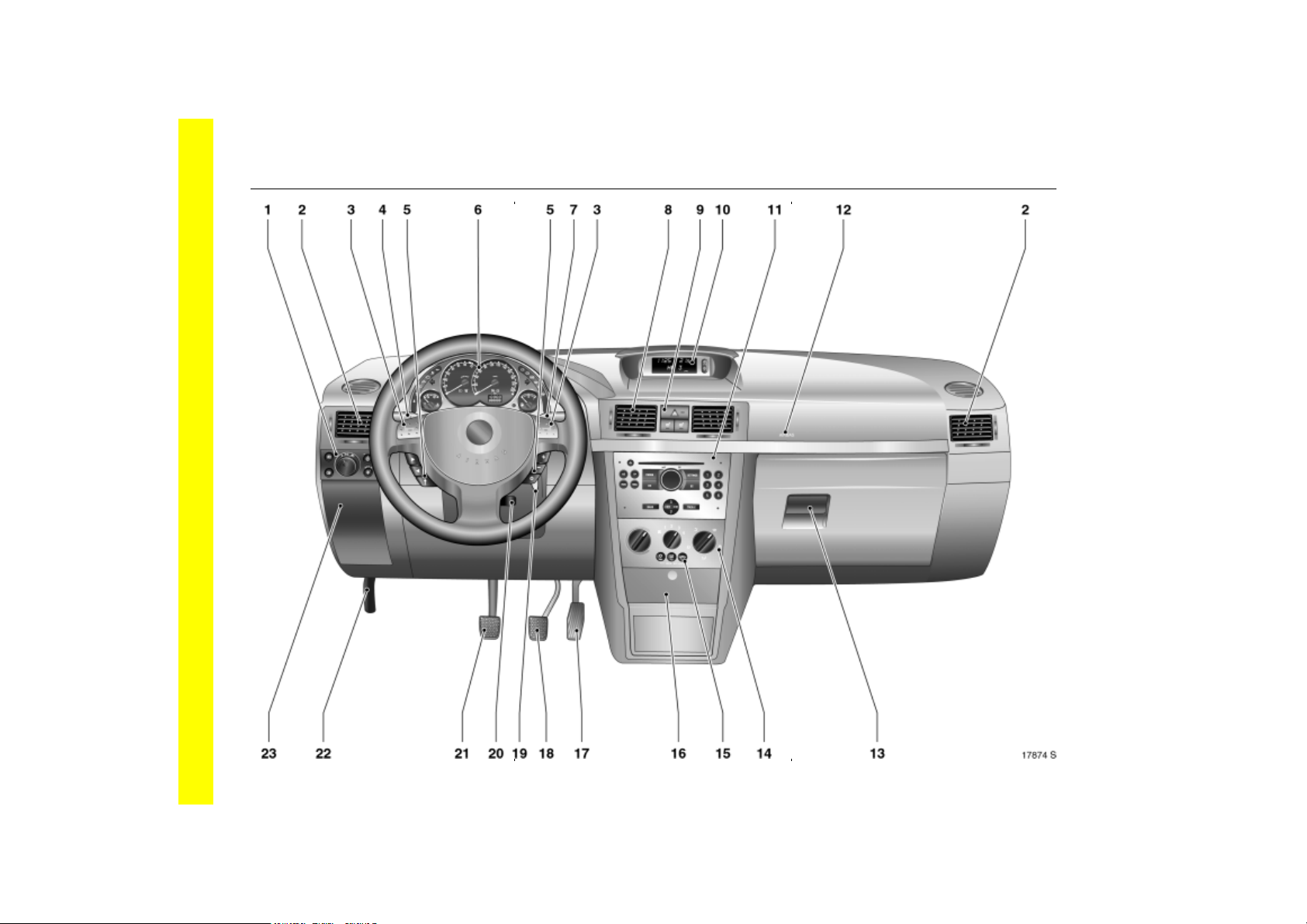
1 Parking lamps, dipped beam ... 3 102
Courtesy lamp ............................ 3 108
Instrument illumination .............. 3 108
Rear fog lamp ............................ 3 104
Fog lamp 3 ................................. 3 103
Headlamp range adjustment 3 3 104
2 Side Air vents .............................. 3 115
3 Horn ...............................................3 12
4 Indicators, headlamp flasher
Dipped beam, main beam............3 11
Ambient lighting 3...................... 3 107
Cruise control 3........................... 3 148
5 Steering wheel remote
control 3 ...................................... 3 111
6 Instruments .................................. 3 82
7 Windscreen wipers and
windscreen washer system,
headlamp washer system 3
and rear window
washer system 3 ...............3 12, 3 100
8 Centre air vents .......................... 3 115
9 Hazard warning lamps ... 3 12, 3 104
LED for
anti-theft alarm system 3 ............3 34
Heated seats 3 ............................ 3 46
10 Central information display
for time, date,
outside temperature,
infotainment system 3 ................ 3 90
11 Infotainment system 3 .............. 3 11
12 Front passenger airbag 3 ........... 3 67
13 Glove compartment ..................... 3 80
14 Climate control ........................... 3 114
15 Air conditioning system 3 ......... 3 114
Heated rear window ........... 3 13, 3 41
Recirculation system 3............... 3 119
16 Ashtray ......................................... 3 79
Accessory socket and
cigarette lighter ........................... 3 78
17 Accelerator pedal .......... 3 135, 3 137
18 Brake pedal .................... 3 135, 3 151
19 Ignition switch
with steering wheel lock .............. 3 15
20 Steering wheel adjustment 3 ....... 3 5
21 Clutch pedal 3 ........................... 3 135
22 Bonnet release lever .................. 3 165
23 Fuse box ..................................... 3 182
1
Page 14

8In Brief
Back to overview
Page 15

9In Brief
Back to overview
1 Side air vents .............................. 3 115
2 Front passenger airbag 3 .......... 3 67
3 Infotainment system 3 ............. 3 111
4 Hazard warning lamps .... 3 12, 3 104
LED for
anti-theft alarm system 3 ............3 34
Heated seats 3 ........................... 3 46
5 Information display
for time, date,
outside temperature,
infotainment system 3 ............... 3 90
6 Centre air vents .......................... 3 115
7 Indicators, headlamp flasher
dipped beam, main beam ............3 11
ambient lighting 3...................... 3 107
cruise control 3 ........................... 3 148
8 Horn ...............................................3 12
9 Instruments ................................... 3 82
10 Windscreen wipers,
windscreen washer system,
headlamp washer system 3
and rear window
washer system 3 ...............3 12, 3 100
11 Parking lamps, dipped beam ....3 102
Courtesy lamp .............................3 108
Instrument illumination ..............3 108
Fog tail lamp ...............................3 104
Fog lamp 3 .................................3 103
Headlamp range adjustment 3 .3 10
12 Bonnet release lever .................. 3 165
13 Steering wheel remote
control 3 ......................................3 111
14 Ignition switch with steering
wheel lock ..................................... 3 15
15 Steering wheel adjustment 3 ....... 3 5
16 Accelerator pedal .......... 3 135, 3 137
17 Brake pedal .................... 3 135, 3 151
18 Clutch pedal 3 ........................... 3 135
19 Ashtray ......................................... 3 79
Accessory socket and
cigarette lighter ........................... 3 78
20 Air conditioning system 3 ......... 3 114
Heated rear window ........... 3 13, 3 41
Recirculation system 3............... 3 119
21 Climate control .......................... 3 114
4
22 Glove compartment .................... 3 80
23 Fuse box ..................................... 3 182
Page 16

10 In Brief
Back to overview
Control indicators
X
B
>
A
Z
v
Seat belt 3,
3 82.
Adaptive Forward Lighting
(AFL) 3, fault,
3 82, 3 106.
Fog lamps 3,
3 83, 3 103.
Engine electronics, immobiliser,
Easytronic 3, Fault,
3 83, 3 27, 3 143.
Exhaust gases 3,
3 83, 3 143.
Airbag systems 3, Belt
tensioners,
3 61, 3 72.
I
O
C
!
j
T
m
r
p
Engine oil pressure,
3 84.
Turn signal lamps,
3 11, 3 84.
Main beam,
3 11, 3 84.
Preheating system 3, Diesel
particle filter 3,
3 86.
Easytronic 3, starting the
engine 3,
3 130.
Easytronic 3, Winter
programme,
3 132.
Cruise control 3,
3 148.
Fog tail lamp,
3 85, 3 104.
Alternator,
3 85.
R
u
S
EPS
v
Y
y
Brake system, clutch system 3,
3 85.
Anti-lock Braking System 3,
3 152.
Engine oil level 3,
3 85.
Electric power steering 3,
3 86.
Electronic Stability Program
Plus
(ESP®
3 146.
Fuel level,
3 86, 3 140.
Seat occupancy recognition 3,
3 72, 3 73.
) 3,
Page 17
11In Brief
Back to overview
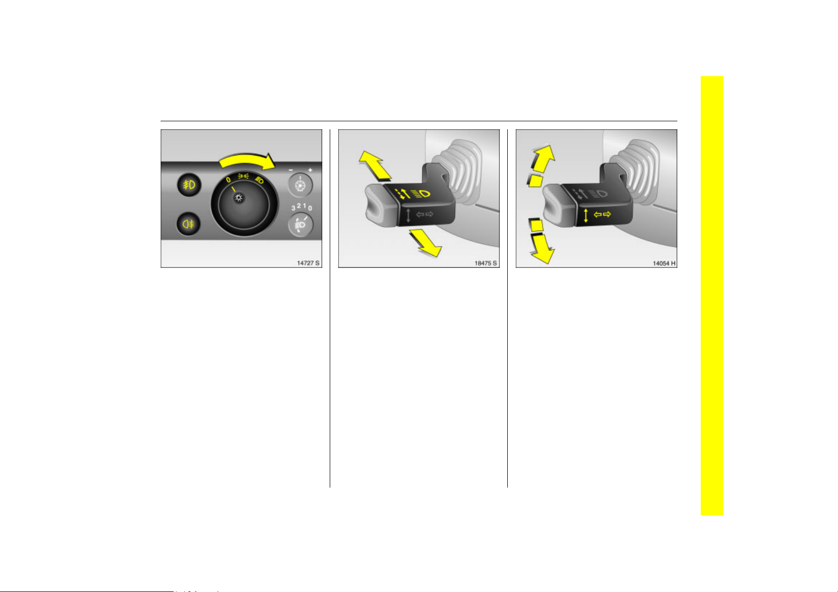
Picture no: 14727s.tif
Exterior lights
Rotate
7 =Off
8 = Parking lamps
9 = Dipped or main beam
Press
> =Fog lamps 3
r = Fog tail lamp
Lighting 3 102, headlamp warning device
3 17.
Picture no: 18475s.tif
Headlamp flash, main beam and
dipped beam
Headlamp flash = Pull stalk towards
steering wheel
Main beam = Push stalk forwards
Dipped beam = Push stalk forwards
again
Main beam, headlamp flash 3 103.
Picture no: 14054h.tif
Turn signals
Right = Lever upwards
Left = Lever downwards
Turn signal lamps 3 103.
Page 18

12 In Brief
Back to overview
Picture no: 14303s.tif
Hazard warning flashers
Operated with the ¨ button.
Hazard warning lamps 3 104.
Picture no: 13991s.tif
Horn: Press j
Airbag system 3 3 67, Steering wheel
remote control 3 3 111.
Picture no: 14055h.tif
Windscreen wipers
& =Fast
% =Slow
$ = Timed interval wipe
§ =Off
Windscreen wipers 3 100 adjustable
intermittent setting 3 3 100, further
information 3 198, 3 215.
Page 19

13In Brief
Back to overview
Picture no: 14056h.tif
Operating windscreen and
headlamp washer systems 3:
Pull stalk towards steering wheel
The wipers will swipe for a few strokes.
The headlamp washer system 3 can be
operated when the lights are on.
Windscreen washer system and headlamp
washer system 3 3 101, Further
information 3 198, 3 215.
Picture no: 14057h.tif
Rear window wiper and washer
system
Wiper on = Push stalk forwards
Wiper off = Pull stalk towards
steering wheel
Washing = Push lever forward
and hold
Rear window wash and wipe system 3 101,
Wiper blades 3 215, Car care 3 198.
Picture no: 13992s.tif
Heated rear window, heated
exterior mirrors 3
Operated with the Ü button.
Climate control 3 114, Heated rear window
3 41.
Page 20
14 In Brief
Back to overview
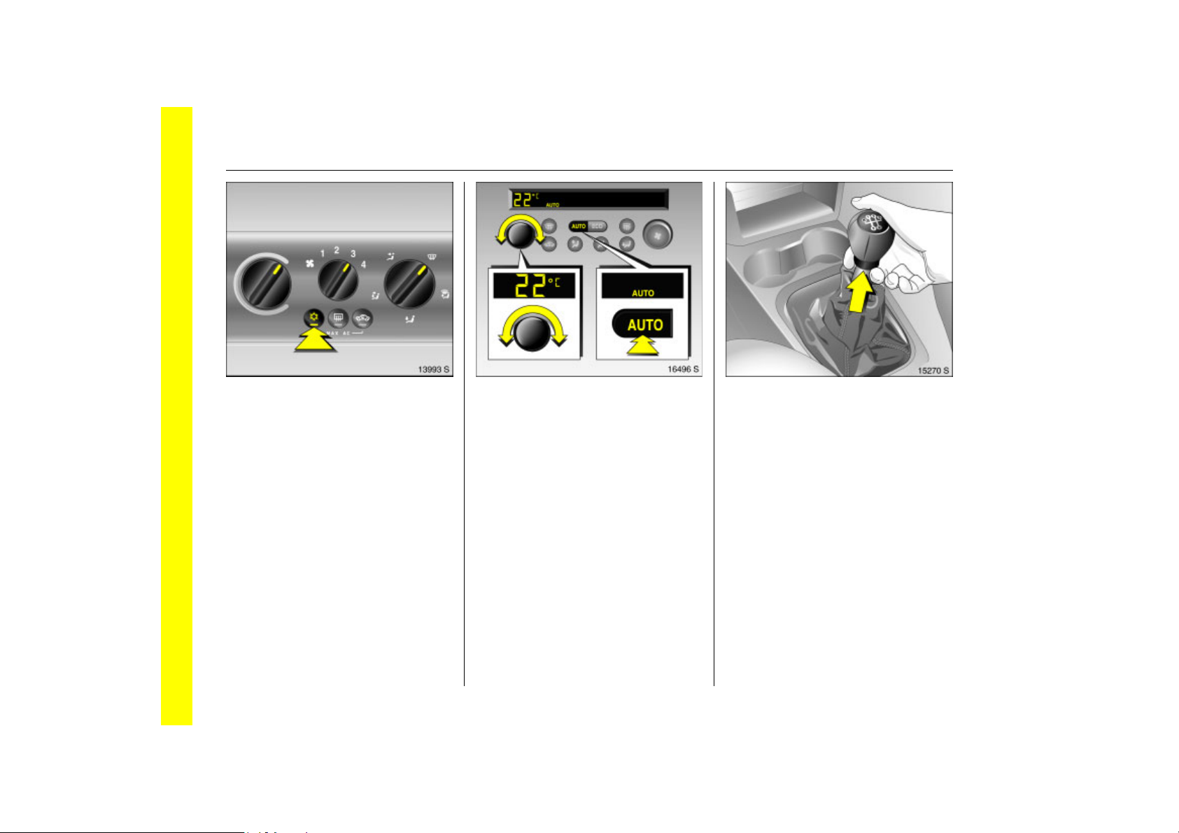
Picture no: 13993s.tif
To clear fogged or icy windows
Turn rotary switch for temperature and air
volume, for air flow also press V,for air
conditioning system 3: button n, climate
control 3: button V.
Climate control 3 114, Air conditioning
system 3 3 119, Climate control system 3
3 122.
Picture no: 16496s.tif
To set automatic mode of climate
control system 3
Press AUTO button, select temperature
with rotary knob, open air vents.
Climate control system 3 3 122.
Picture no: 15270s.tif
Manual transmission
Reverse gear: With vehicle stationary, wait
3 seconds after depressing the clutch, then
lift the ring below the gear knob and
engage gear.
If the gear does not engage, set the lever in
neutral, release the clutch pedal and
depress again; then repeat gear selection.
Manual transmission 3 14.
Page 21
Before starting off, check
Back to overview
z Tyre pressure and tyre condition 3 155,
3 228.
z Engine oil level and fluid levels 3 209 to
3 216.
z All windows, mirrors, exterior lighting
and number plates are free from dirt,
snow and ice and operational.
z Seats, seat belts and mirrors are
correctly adjusted. 3 44, 3 59, 3 36.
z Check brake function at low speed,
particularly if the brakes are wet.
15In Brief
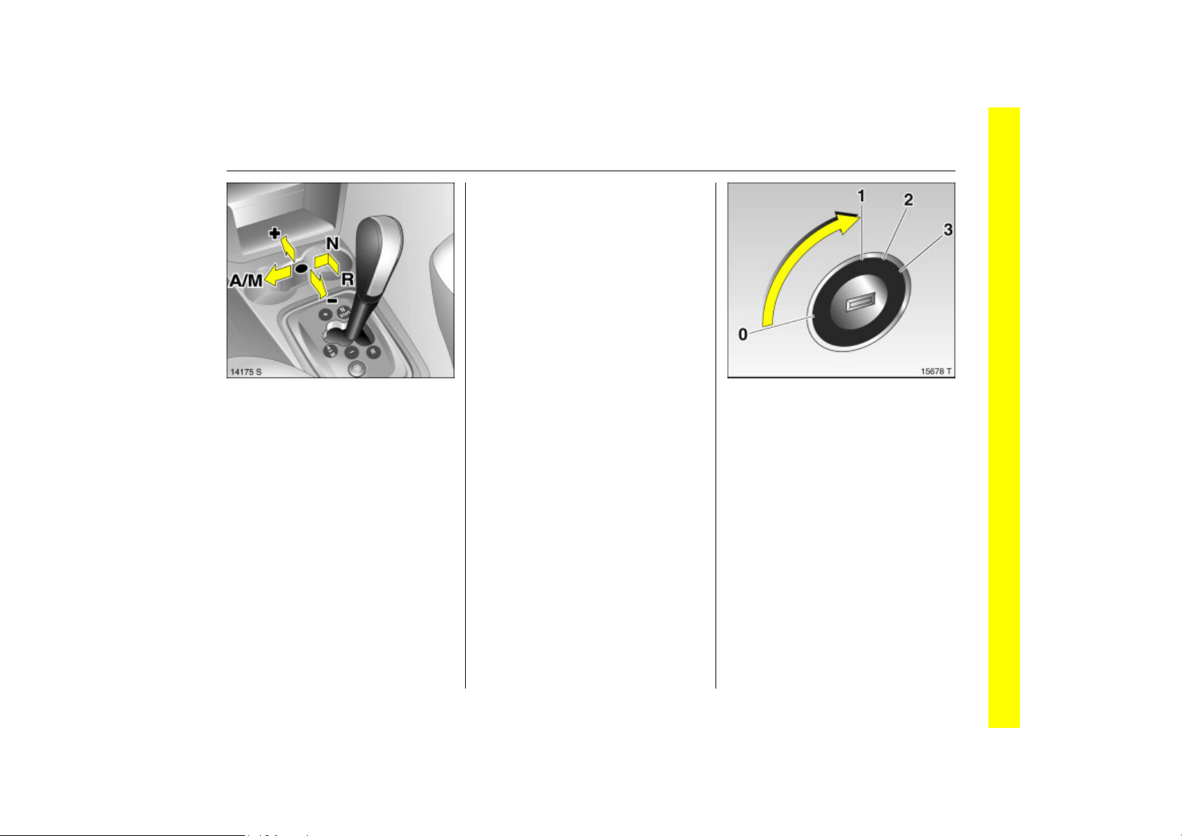
Picture no: 14175s.tif
Automated manual
transmission 3
N =Idle/start position
o =Driving position
+ = Higher gear
- = Lower gear
A/M = Switch between Automatic and
Manual mode
R = Reverse gear
(with selector lever lock)
To move the selector lever from N to R
press the button on the lever.
Only start in N with foot brake applied.
Automated manual transmission 3 3 129.
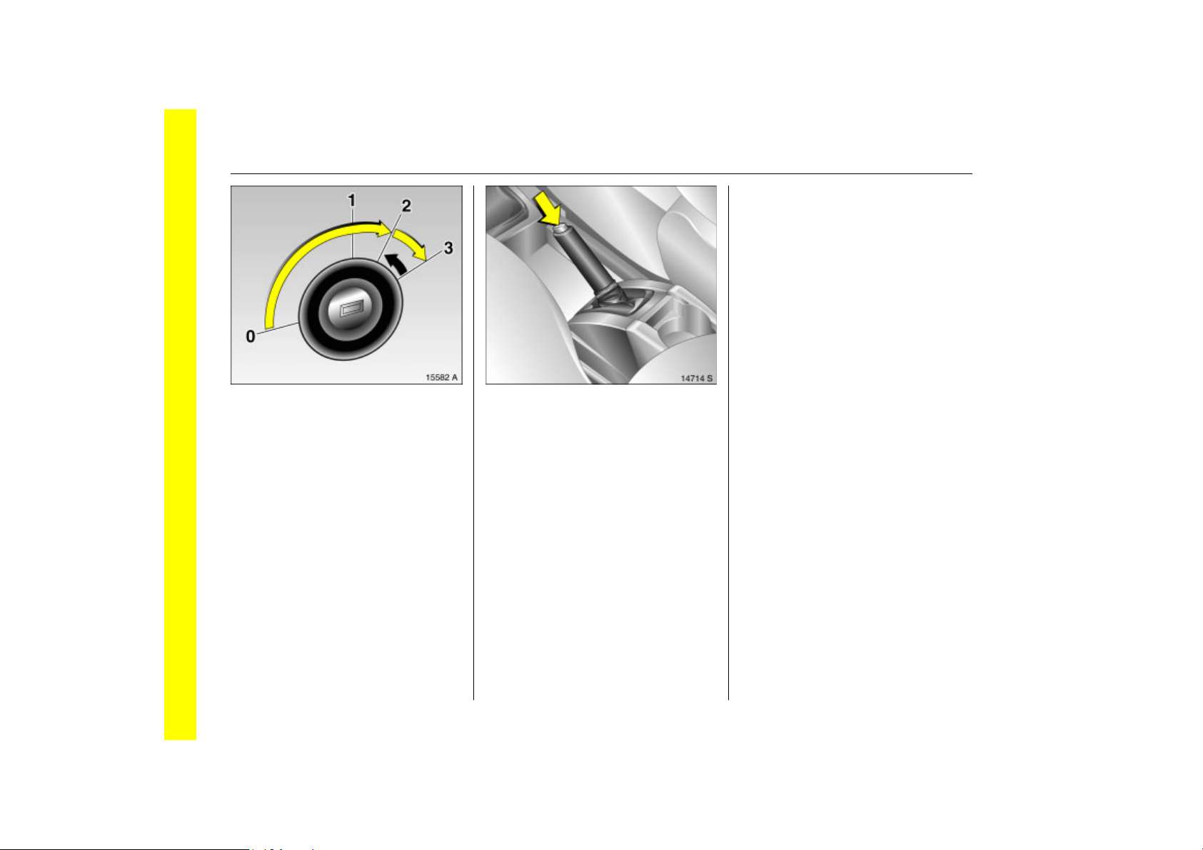
Picture no: 15678t.tif
Steering wheel lock and ignition
Turn key to position 1. Move the steering
wheel slightly to release the steering wheel
lock.
0 =Ignition off
1 = Steering free, ignition off
2 =Ignition on, with diesel engine: pre-
heating
3 =Starting
Page 22
16 In Brief
Back to overview
Picture no: 15582a.tif
Starting the engine
Depress clutch and brake, manual
transmission automated 3 in N, do not
press the accelerator, in diesel engine
vehicles turn the key to positing 2 until the
warning lamp ! goes out, turn key to
position 3; let go of the key when the
engine is running.
Before restarting or switching off the
engine, turn key back to 0.
To switch on the ignition, only turn the key
to 2.
Picture no: 14714s.tif
Releasing the hand brake: Raise
lever slightly, Press release
button, Lower lever fully
Hand brake 3 153.
Parking the vehicle
z Always apply the handbrake without
pressing the release button. On an
incline, apply as tight as possible. To
reduce activation force, depress foot
brake at the same time.
z Switch off engine and ignition. Turn the
ignition key to position 0 and pull it out.
Turn the steering wheel until it is clear
that the steering lock has engaged (antitheft protection).
On vehicles with manual transmission
automated 3, control indicator R
flashes for a few seconds after the
ignition is switched off if the hand brake
has not been applied.
z If the vehicle is on the flat or on an
incline, engage first gear before
switching off the ignition. On an uphill
slope, also turn the front wheels out from
the kerb.
If the vehicle is facing downhill, engage
reverse gear before switching off the
ignition. Also turn the front wheels into
the kerb.
z Lock the vehicle by pressing button p on
the remote key fob.
To activate the anti-theft locking
system 3 and anti-theft alarm system 3,
press button p twice.
Page 23

17In Brief
Back to overview
Advice when parking
z Do not park the vehicle on flammable
ground as combustion could occur due
to the high exhaust temperatures.
z Close window, sliding roof 3 and tilting
roof 3.
z The engine cooling fans may run after
the engine has been switched off, 3 209.
z After running at high engine speeds or
with high engine loads, operate the
engine briefly at a low load or run in
neutral for approx. 30 seconds before
switching off in order to protect the
turbocharger 3.
Remote control 3 28, central locking
system 3 30, anti-theft warning system 3
3 34, parking vehicle for longer periods
3 217.
Interesting functions
Page 24

18 In Brief
Back to overview
Flexible Seat System (FlexSpace)
The back seat of your vehicle has three
seats or, with the centre seat lowered, two
seats with maximum seating space. The
outer seats can be lowered to obtain a level
loading surface.
Sliding outboard rear seats front-rear
Picture no: 14178s.tif
z Pull handle under seat.
z Slide seat.
z Release handle and allow seat to
engage in position.
When pushing the seats back, to prevent
damage make sure the backrests are not in
their furthest back position.
Adjust or fold backrest of rear outboard
Picture no: 14179s.tif
seats
z Pull handle on outboard side of seat.
z Guide backrest into the relevant position.
z Release handle and allow seat to audibly
engage in position.
Page 25

The backrest can engage in several
Back to overview
positions. In addition, the backrest can be
folded all the way down to the seat when
extending the luggage compartment.
9 Warning
To prevent injuries, always hold back
seat backrest firmly and guide
downward when folding.
19In Brief
Lower centre seat
Picture no: 14728s.tif
z House centre seat belt in the holder in
the roof.
z Insert seat belts into recesses in seat
cushion.
z Slide centre seat head rest all the way
down.
z Pull release handle at rear of centre
backrest. Tilt backrest forward and
engage.
Variant 1 with three rear seats
Picture no: 14730s.tif
z Adjust backrest to centre position.
z Pull handle beneath seat. Slide seat all
the way forward, then outward toward
the door and then further forward to the
desired position.
z Release handle and allow seat to
engage in position.
z Raise centre seat.
Page 26

20 In Brief
Back to overview
Variant 2 with two rear seats, with
Picture no: 14729s.tif
maximum seating space
z Lower centre seat.
z Adjust backrest to centre position.
z Pull handle beneath seat. Slide seat all
the way back, then toward the centre of
the vehicle and then further rearward to
the desired position.
z Release handle and allow seat to
engage in position.
Lower outboard seats
Picture no: 14716s.tif
z Pull seat belt from belt guide at backrest.
z Fold down outboard rear seat backrests.
z To achieve a level loading surface, pull
release handle on back of backrest and
push seat down until it latches into
position.
Picture no: 14125s.tif
Airbag system
The airbag system consists of several
internal systems.
Front airbag system
The front airbag system will be triggered in
the event of a serious accident involving a
frontal impact and forms safety cushions
for the driver and front passenger. The
forward movement of the driver and front
passenger is checked and the risk of
injuries to the upper body and head
thereby substantially reduced.
Page 27
21In Brief
Back to overview
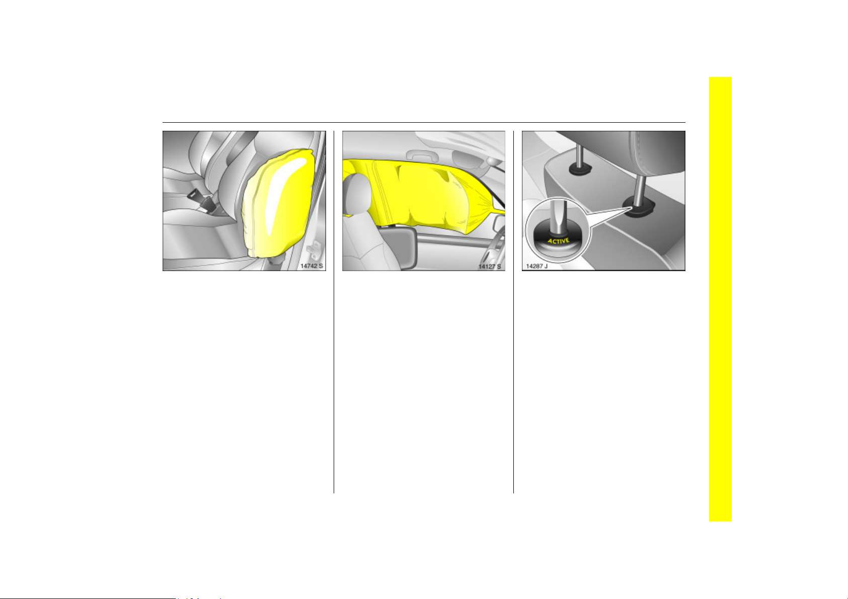
Side airbag system 3
Picture no: 14742s.tif
The side airbag is triggered in the event of
a side-on collision to form a safety cushion
for the driver or front passenger in the
respective door area. This substantially
reduces the risk of injury to the upper body
and pelvis.
Curtain airbag system 3
Picture no: 14127s.tif
In the event of a side-on collision, the
curtain airbag system triggers and
provides a safety barrier in the head area
of the vehicle. This considerably reduces
the risk of injury to the head in the event of
a side-on collision.
Airbag System 3 3 67.
Picture no: 14287j.tif
Active head restraints 3 on front
seats
In the event of a rear-end impact, the
active head restraints tilt forwards slightly.
The head is more effectively supported by
the head restraint and the risk of whiplash
injury is reduced.
Active head restraints can be recognised
by the word ACTIVE.
Head restraints 3 46.
Page 28
22 In Brief
Back to overview
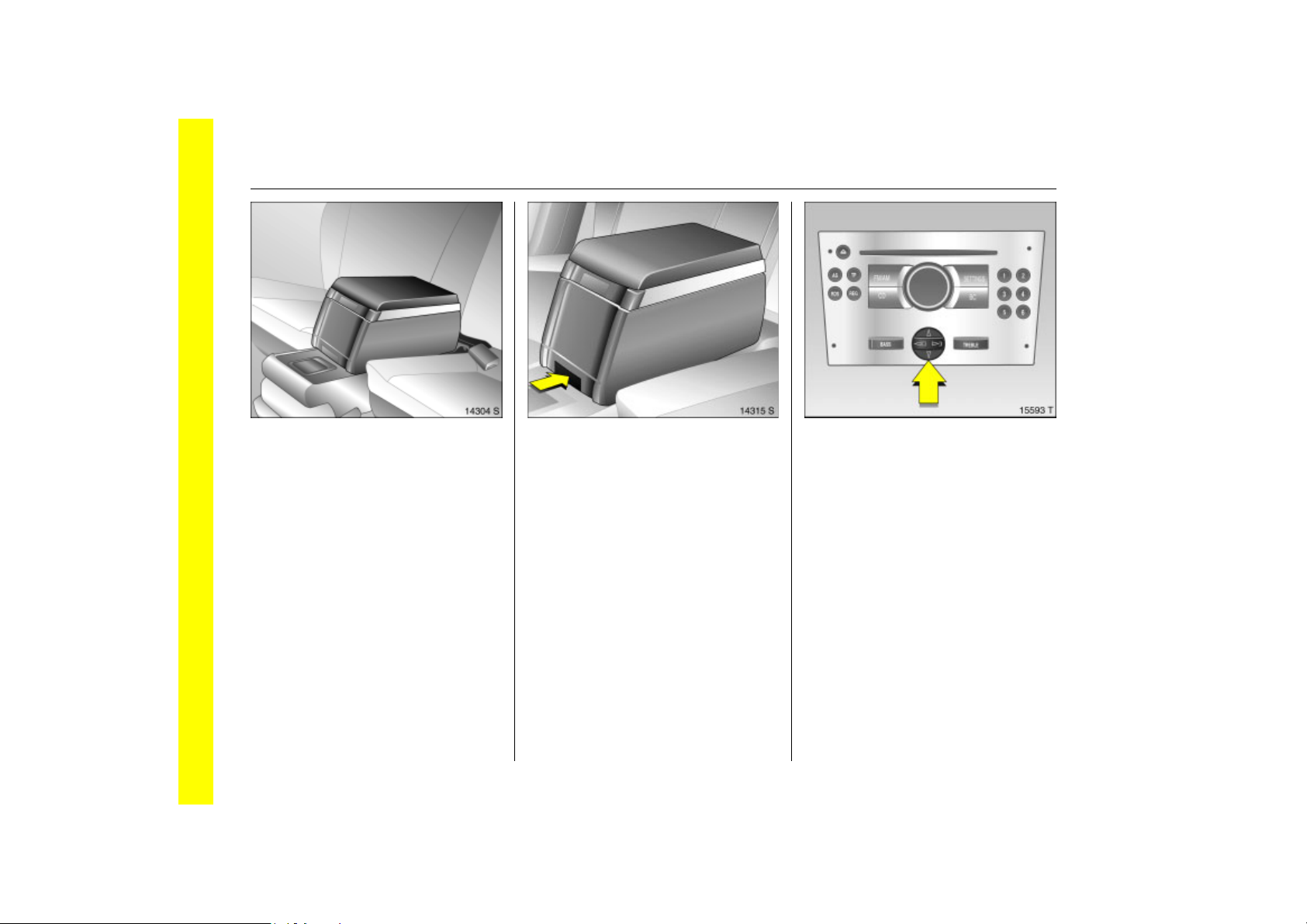
Picture no: 14304s.tif
Travel Assistant 3
The Travel Assistant Contains
z Armrest.
z Tray.
z Drink holders.
The Travel Assistant is mounted on the
lowered centre seat.
Dismantling the Travel Assistant
Picture no: 14315s.tif
z Press lower button on the
Travel Assistant.
z Pull Travel Assistant upwards out of
recesses.
z There is a carrying handle on the back to
facilitate transport.
Picture no: 15593t.tif
Operating menus via the
information display 3
Menu options are selected using menus
and using the buttons/four-way button or
the multifunction button of the
Infotainment system 3 or the buttons 3 on
the steering wheel. The respective menu
options are shown on the display.
Selection using four-way button: press
four-way button at top, bottom, left or
right.
Page 29
Ü Board Computer 19,5° 19:36
Back to overview
BC 1 All values
BC 2
Timer
1
257.0 km
Ø40km/h
31.0 Ltr.
8
Ø 7.0 Ltr./100km
23In Brief
Selection using multifunction button 3:
Picture no: 15559t.tif
rotate and press multifunction button.
To exit a menu, turn the multifunction
button left or right to Return or Main and
select.
To select with steering wheel buttons 3
Picture no: 14034s.tif
Select menu options via the menus and the
buttons.
Information display 3 90.
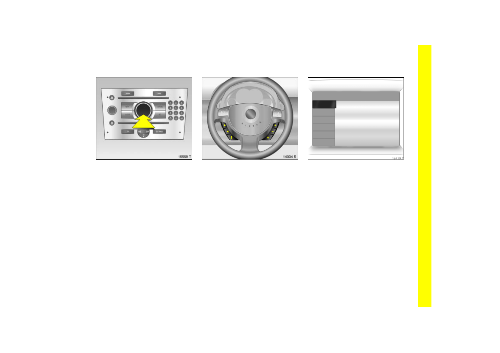
Picture no: 16719t.tif
Trip computer 3
Functions:
z Range
z Instantaneous consumption
z Distance travelled
z Average speed
z Effective consumption
z Average consumption
z Stop watch
Trip computer 3 97.
Page 30
24 In Brief
Back to overview
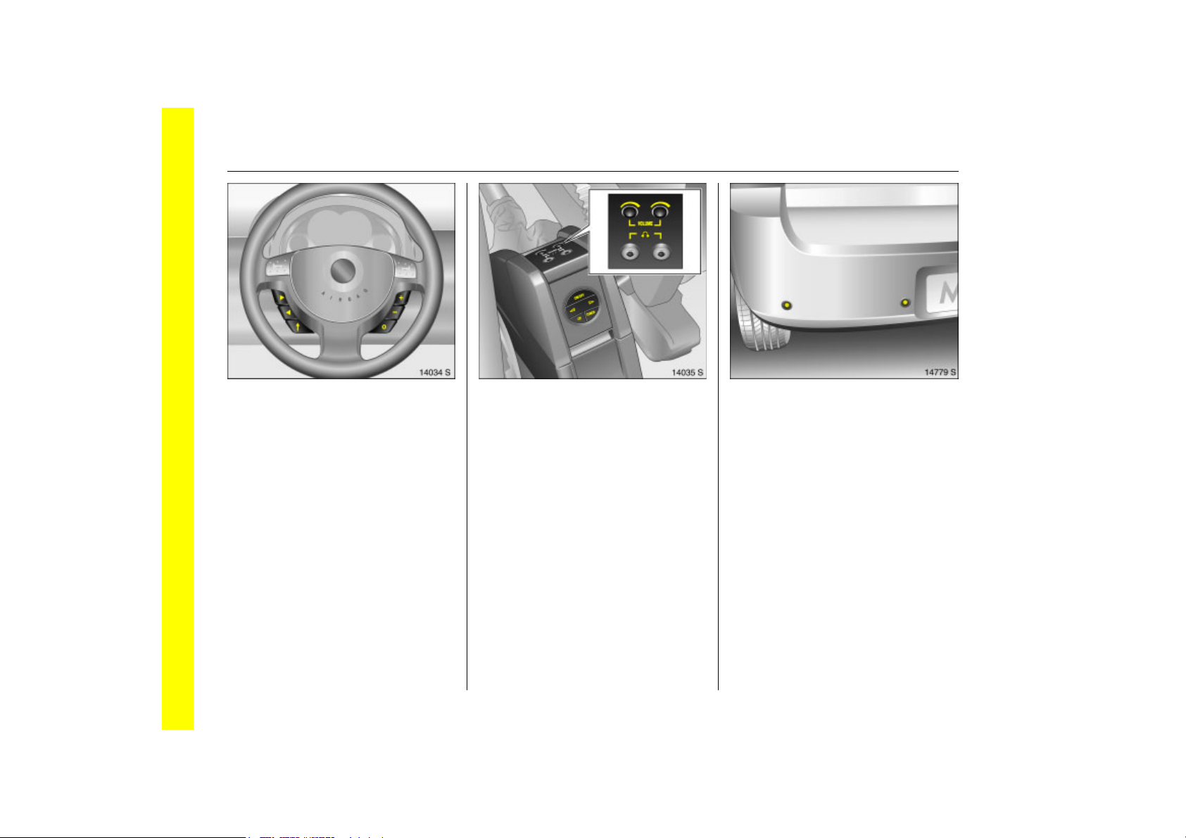
Picture no: 14034s.tif
Steering wheel remote control 3
The functions of the infotainment system
and the information display can be
operated with the remote control on the
steering wheel.
Steering wheel remote control 3 3 111,
Infotainment system 3 111.
Picture no: 14035s.tif
Rear seat audio system 3
Twin Audio allows rear seat occupants the
choice between the audio source played on
the Infotainment system or the alternative
audio source.
Rear seat audio system 3 3 112.
Picture no: 14779s.tif
Ultrasonic parking sensors 3
When reverse gear is selected, the park
pilot switches itself on automatically.
An acoustic warning sounds when the
vehicle approaches an obstacle behind.
Ultrasonic parking sensors 3 3 150.
Page 31
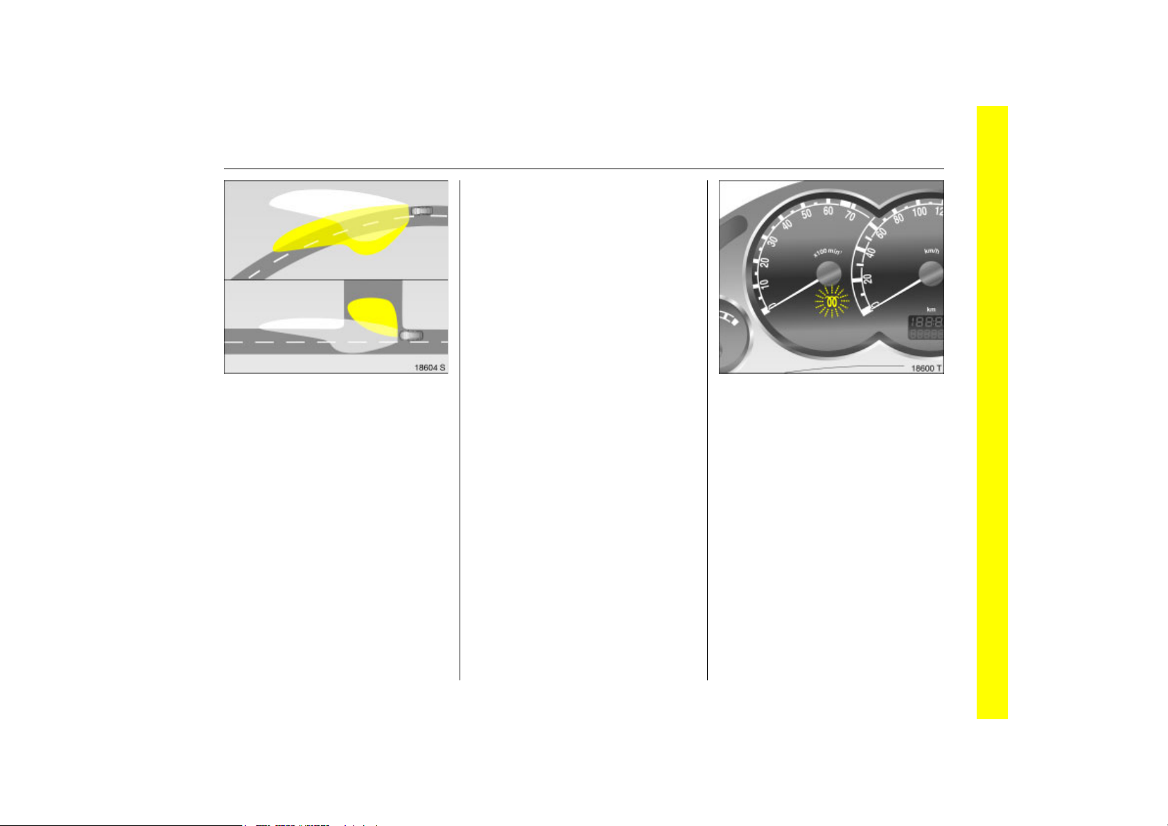
Picture no: 18604s.tif
Back to overview
Adaptive Headlight (AFL) 3
The system provides better illumination of
the road on corners and curves.
Curve lighting
The light beam pivots based on
steering wheel position and speed
(from approx. 10 km/h).
The headlamps shine at an angle of up
to 15 to the right or left of the direction of
travel.
Cornering light
An additional lamp comes on at certain
steering wheel settings (after rotation
of approx. 90), turn signal settings and
speeds (up to approx. 40 km/h).
The lamp beam projects at a 90 angle to
the left or right of the vehicle up to a
distance of approx. 30 metres.
Reversing function
Turning the lights on, selecting reverse
gear and activating the turn signal
activates the cornering light for the
relevant side. When the turn signal is
switched off, the cornering light continues
to illuminate for 15 seconds.
Adaptive forward lighting 3 3 106.
Diesel particle filter 3
The diesel particle filter system filters
harmful soot particles out of the exhaust
gases. The system includes a self-cleaning
function that run automatically during
driving. The filter is cleaned by burning off
the soot particles at high temperature.
This process takes place automatically
under set driving conditions and may take
up to 25 minutes. Fuel consumption may
be higher during this period. The emission
of smells and smoke during this process is
normal.
25In Brief
Picture no: 18600S.tif
Under certain driving conditions, e.g. short
journeys, the system may not clean itself
automatically.
If the filter requires cleaning and previous
driving conditions did not enable
automatic cleaning, control indicator !
flashes.
Further instructions 3 144.
Page 32
26 Keys, doors, windows, slide and tilt sunroof
Back to overview
Keys, doors, windows,
slide and tilt sunroof
Replacement keys ............................... 26
Key with retractable key blade 3 ...... 26
Car Pass................................................ 26
Electronic immobiliser.......................... 27
Radio remote control .......................... 28
Central locking system ........................ 30
Malfunction in remote control ............ 32
Malfunction in central
locking system................................. 32
Tailgate ................................................ 32
Anti-theft alarm system 3 .................. 34
Child safety locks................................. 36
Exterior mirrors..................................... 36
Interior mirror ....................................... 38
Manual window operation.................. 39
Electric windows 3............................... 39
Sun roof and tilting roof 3.................. 42
Replacement keys
The key number is specified in the
Car Pass 3.
The key is part of the electronic
immobiliser.
Locks 3 198.
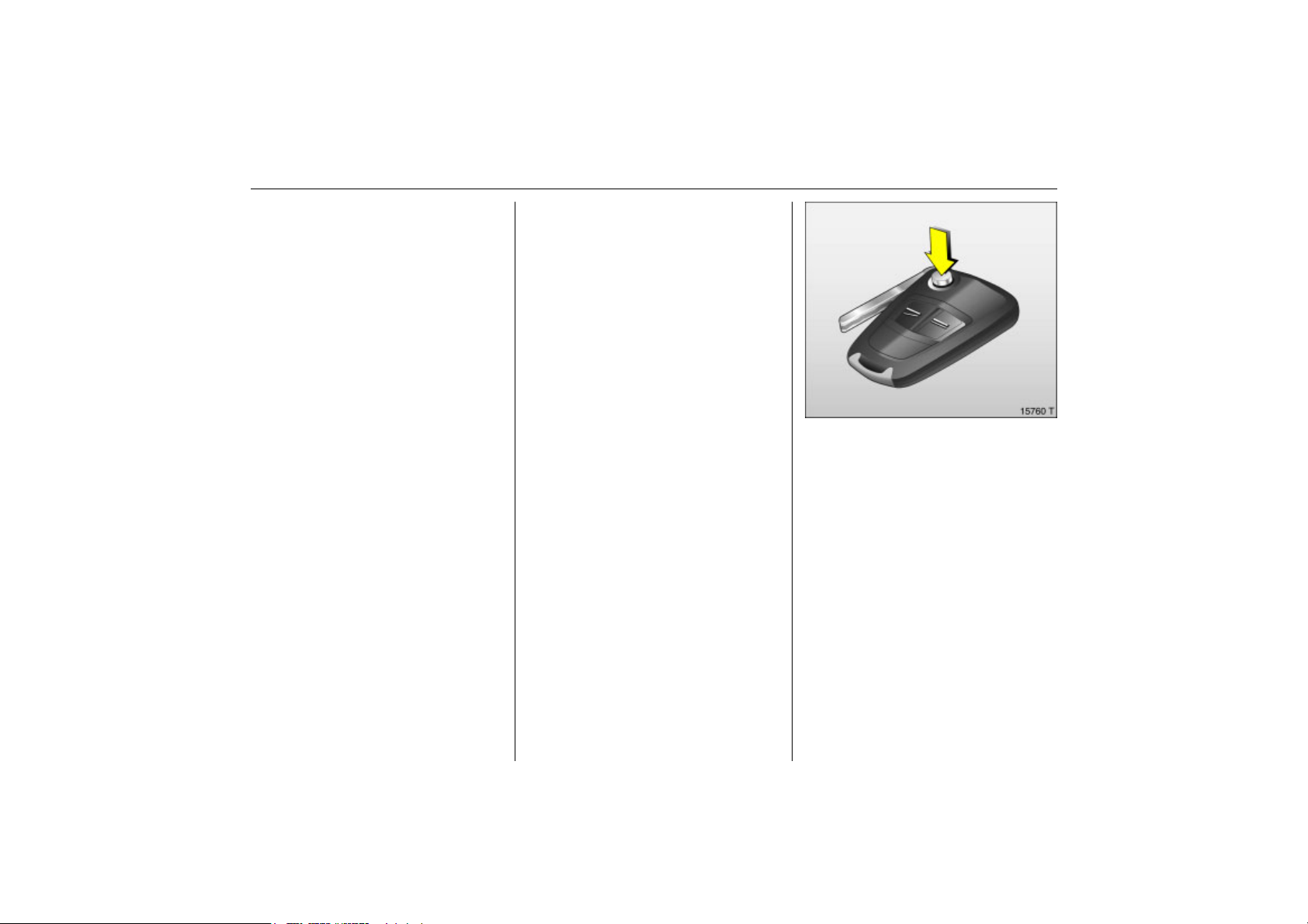
Picture no: 15760t.tif
Key with retractable key blade 3
Press button to extend. To retract, press
button and audibly engage key blade.
Car Pass
The Car Pass contains safety-related
vehicle data and should therefore be kept
in a safe place.
When the car is taken to a workshop, the
Car Pass data is needed in order to
perform certain operations.
Page 33
27Keys, doors, windows, slide and tilt sunroof
Back to overview
If control indicator A illuminates after the
engine has started, there is a fault in the
engine electronics or transmission
electronics 3 3 83, 3 133, 3 143 or there is
water in the diesel fuel filter 3 3 212.
Note
The immobiliser does not lock the doors.
Therefore, always lock the vehicle before
leaving it unattended and enable the
anti-theft alarm system 3 3 34.
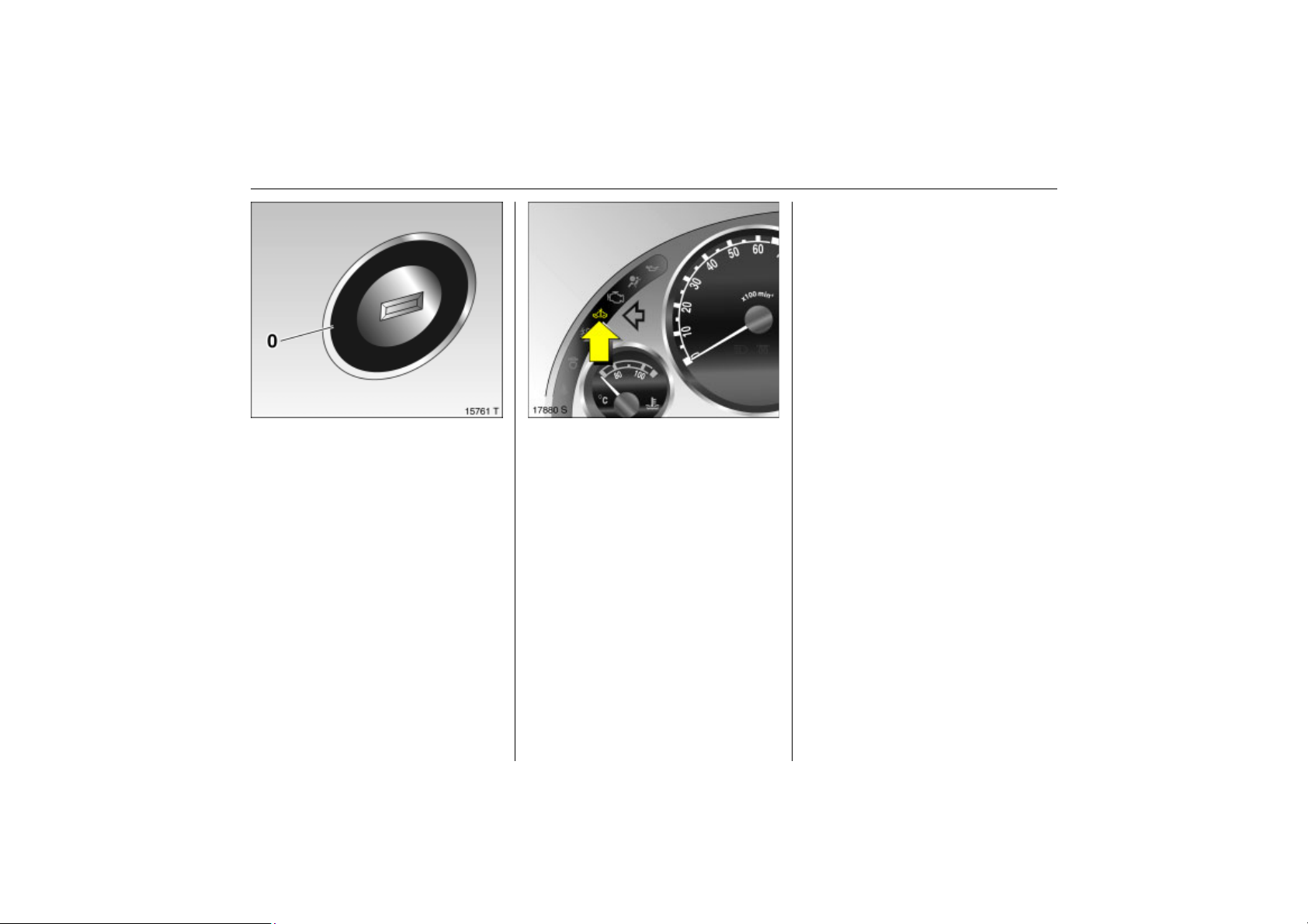
Picture no: 15761t.tif
Electronic immobiliser
The system checks whether the vehicle is
allowed to start with the key used. Once
the transponder in the key is recognised,
the vehicle can be started.
The electronic immobiliser activates
automatically when the key is removed
from the ignition switch.
Control indicator for immobilizer A
Picture no: 17880s.tif
Control indicator A illuminates briefly
when the ignition is switched on.
If the control indicator flashes when the
ignition is on, there is a fault in the system;
the engine cannot be started. Switch off
the ignition and then repeat the start
attempt.
If the control indicator A continues to
flash, please try to start the engine using
the second key and contact a workshop.
Page 34
28 Keys, doors, windows, slide and tilt sunroof
Back to overview
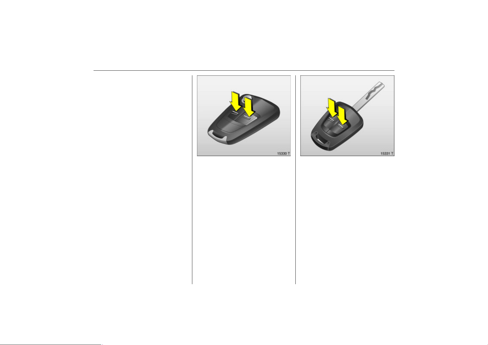
Radio remote control
Depending on equipment level, the vehicle
comes equipped with one of the remote
controls depicted on this page.
The remote control is integrated in the key.
Used to operate:
z Central locking system,
z Mechanical anti-theft locking system 3,
z Anti-theft alarm system 3.
In vehicles with electric windows in all
doors 3, the radio remote control can be
used to closed the windows.
The remote control has a range of
Picture no: 15330t.tif
approx. 5 metres. This range can be
affected by outside influences. Aim the
remote control at the vehicle to operate.
The hazard warning lamps flash to confirm
remote control operation.
Handle the remote control with care,
Picture no: 15331t.tif
protect it from moisture and high
temperatures and avoid unnecessary
operation.
Page 35
29Keys, doors, windows, slide and tilt sunroof
Back to overview
Fault
If the central locking system cannot be
operated with the remote control, it may be
due to the following:
z Range exceeded.
z Remote control battery voltage too low.
Change battery.
z Operating the remote control several
times in quick succession outside the
range of the vehicle can result in the
remote control no longer being
recognised so that it has to be resynchronised.
z If the central locking system is
overloaded as a result of repeated
operation at short intervals. The power
supply is cut off for a brief period.
z Interference from higher-power radio
waves from other sources.
Opening the vehicle 3 32.
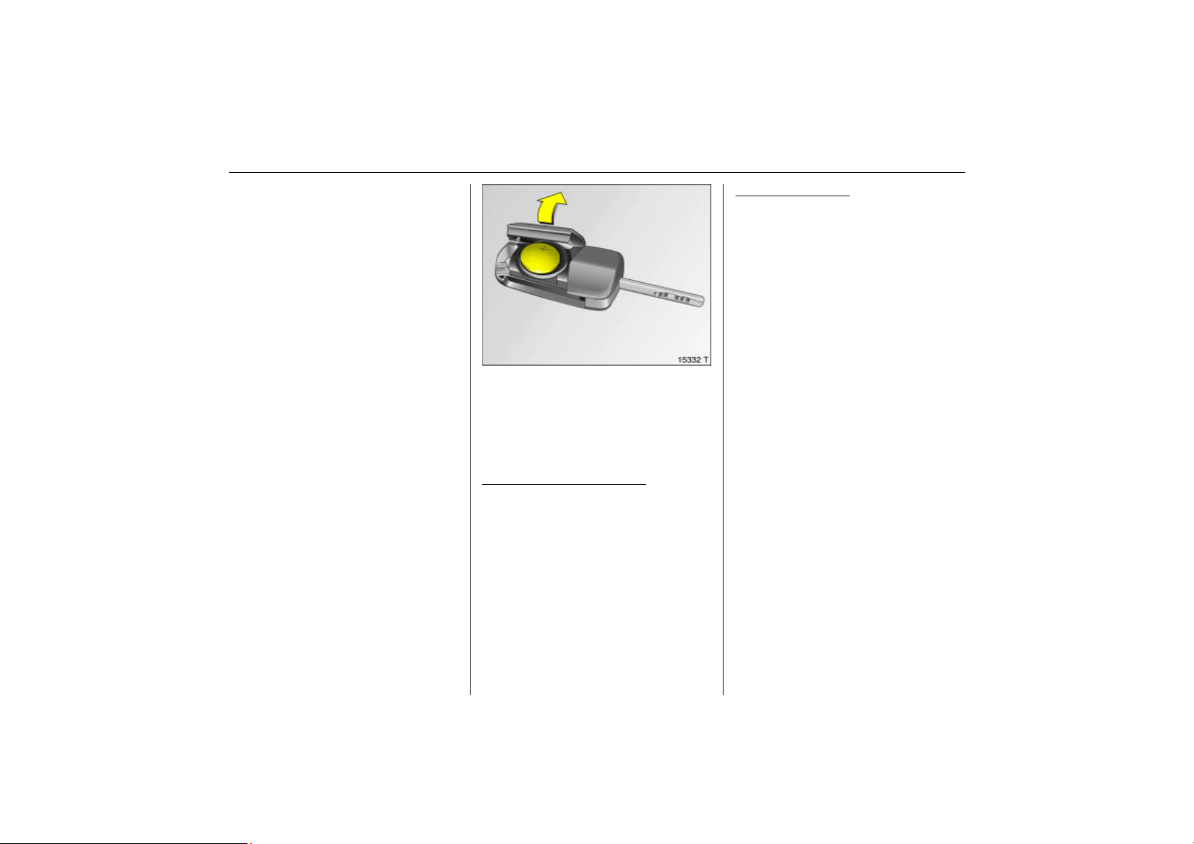
Remote control battery replacement
Picture no: 15332t.tif
Replace the battery as soon as the range
of the remote control begins to shrink.
Batteries do not belong in household
waste. They must be disposed of at an
appropriate recycling collection point.
Key with retractable key blade
Fig. 15330 T on previous page.
Extend the key 3 26. Open the remote
control. Replace the battery (battery type
CR 20 32), noting installation position.
Close the remote control and synchronise.
, see
Key with fixed key bit
previous page.
Have the battery changed in a workshop.
Synchronise remote control
After changing the battery, unlock the
door using the key in the lock. The radio
remote control is synchronised by inserting
the key in the ignition lock.
, see Fig. 15331 T on
Page 36
30 Keys, doors, windows, slide and tilt sunroof
Back to overview
When the mechanical anti-theft locking
system 3 is enabled, the doors cannot be
unlocked by pulling up the lock buttons.
Country-specific version 3: pressing once
unlocks the driver’s door, and pressing
twice unlocks the entire vehicle.
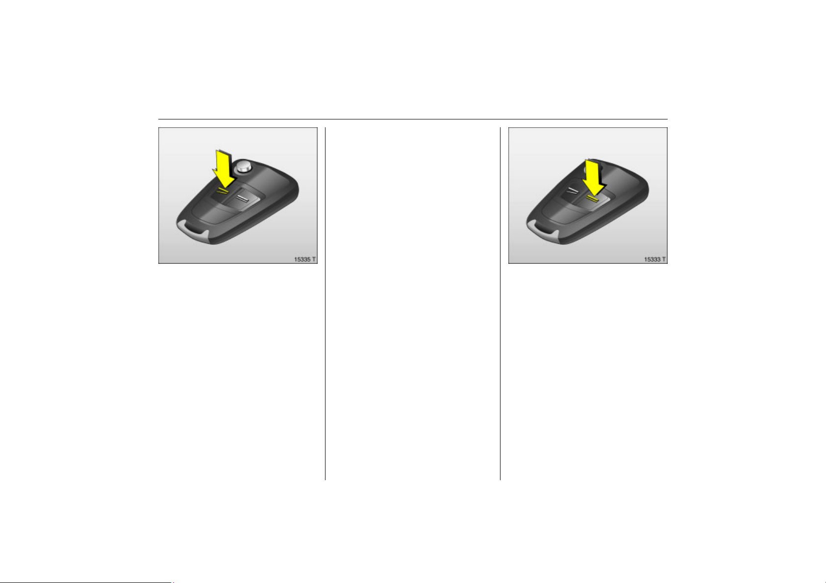
Picture no: 15335t.tif
Central locking system
Unlock and lock doors, tailgate and fuel
filler flap.
To unlock
Press button q on remote control
– or from the inside –
Release lock button on driver’s door.
To open the door, pull the handle. Open
the luggage compartment by pulling the
button in the handle recess.
To lock
Picture no: 15333t.tif
Close doors, luggage compartment and
tank flap.
Press button p of the radio remote control
– or from the inside –
Press lock button on driver’s door when the
doors are closed.
Page 37
31Keys, doors, windows, slide and tilt sunroof
Back to overview
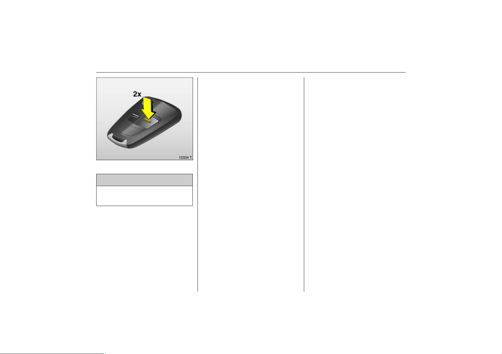
Mechanical anti-theft locking system 3
Picture no: 15334t.tif
9 Warning
Do not use the system if there are people
in the vehicle! The doors cannot be
unlocked from the inside.
All doors must be closed.
If the ignition was on, the driver’s door
must be opened and closed once so that
the vehicle can be secured.
All doors are secured against opening.
Within 10 seconds of locking, press the
p button on the remote control again.
The mechanical anti-theft locking system is
switched off when the vehicle is unlocked.
Note
z To prevent the driver from being
inadvertently locked out, the button on
the driver’s door cannot be depressed
when the door is open.
z If the driver’s door is not closed properly,
the central locking system will unlock
again immediately after locking.
z The doors lock again automatically a
short time after unlocking the vehicle
using the remote control if no door is
opened in the meantime.
z To lock the doors from inside (e.g. to
prevent unwanted entry from outside),
push down lock button on driver’s door.
z Locked doors unlock automatically if an
accident of a certain severity occurs (to
permit outside assistance) – Prerequisite:
Ignition must not be switched off.
Fault
If the central locking cannot be operated,
this can be for one of the following reasons:
z If the central locking system is
overloaded as a result of repeated
operation at short intervals. The power
supply is cut off for a brief period.
z Faulty fuse in fuse box 3 182.
To eliminate the cause of the fault, contact
a workshop.
Opening driver’s door with key.
Page 38
32 Keys, doors, windows, slide and tilt sunroof
Back to overview
Malfunction in central
locking system
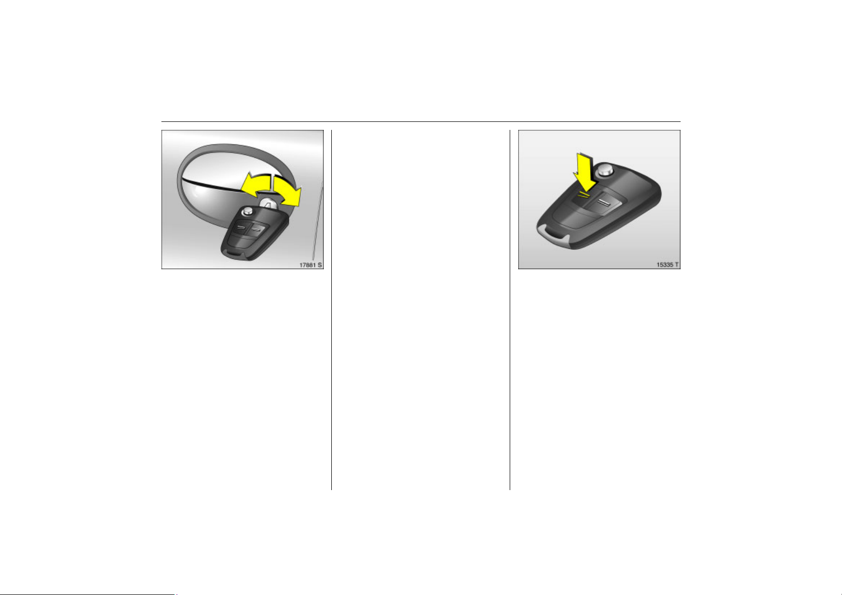
To unlock
Turn key anticlockwise in driver’s door lock,
return to the vertical position and remove.
The driver’s door is unlocked. The other
doors can be unlocked by pulling the
interior lock buttons (not possible if the
anti-theft locking system is enabled 3).
Switch on the ignition to deactivate the
anti-theft alarm system 3.
To lock
With the driver’s door open, press the
interior lock button of the other doors.
Picture no: 17881s.tif
Malfunction in remote control
To unlock
Turn key anticlockwise in driver’s door lock,
return to the vertical position and remove.
The entire vehicle is unlocked. Switch on the
ignition to deactivate the anti-theft alarm
system 3.
To lock
With the driver’s door closed, turn the key
clockwise in the lock, return to the vertical
position and remove. The entire vehicle is
locked.
Close the driver’s door. Turn the key
clockwise in the lock, return to the vertical
position and remove. The fuel filler flap
cannot be locked.
Picture no: 15335t.tif
Tailgate
To unlock
Press button q on the remote control, the
tailgate and the doors will be unlocked.
Page 39
33Keys, doors, windows, slide and tilt sunroof
Back to overview
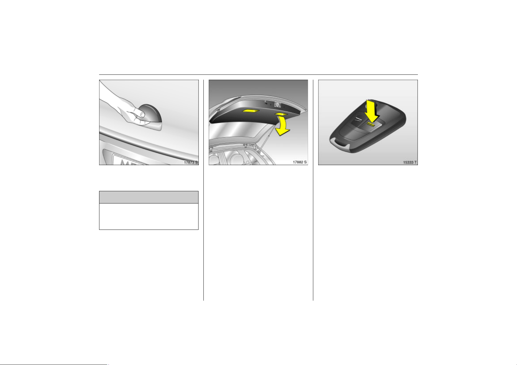
To open
Picture no: 17873s.tif
The tailgate is opened by pulling on the
button in the handle recess.
9 Warning
Do not drive with the tailgate open or
ajar, e.g. when transporting bulky
objects, since toxic exhaust gas could
penetrate the interior.
After fitting certain accessories, it might
not be possible to keep the tailgate in the
open position.
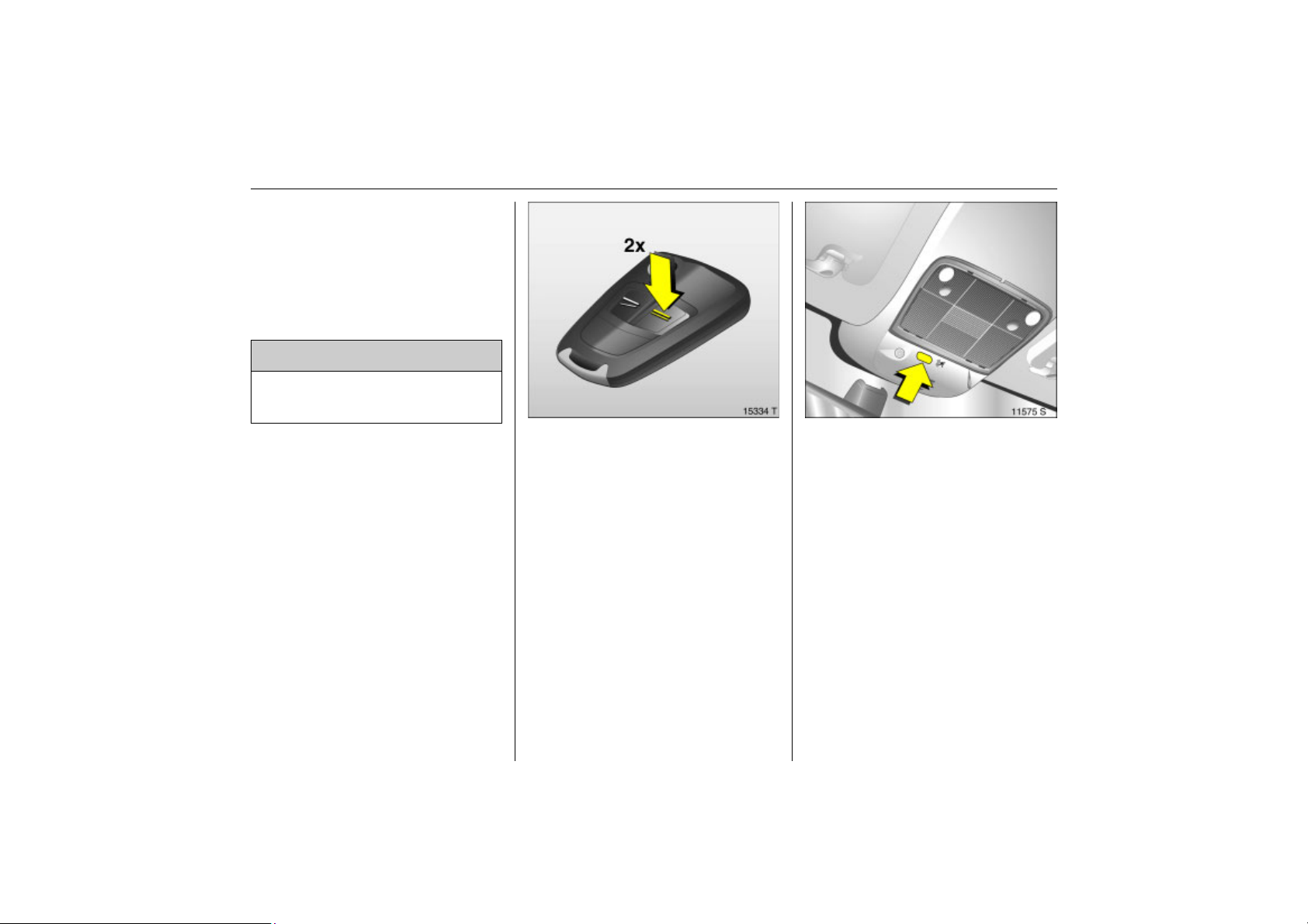
To close
Picture no: 17882s.tif
Close the tailgate using the handle on the
inside of the tailgate.
Do not press the release button in the trim
recess while closing as this will unlock it
again.
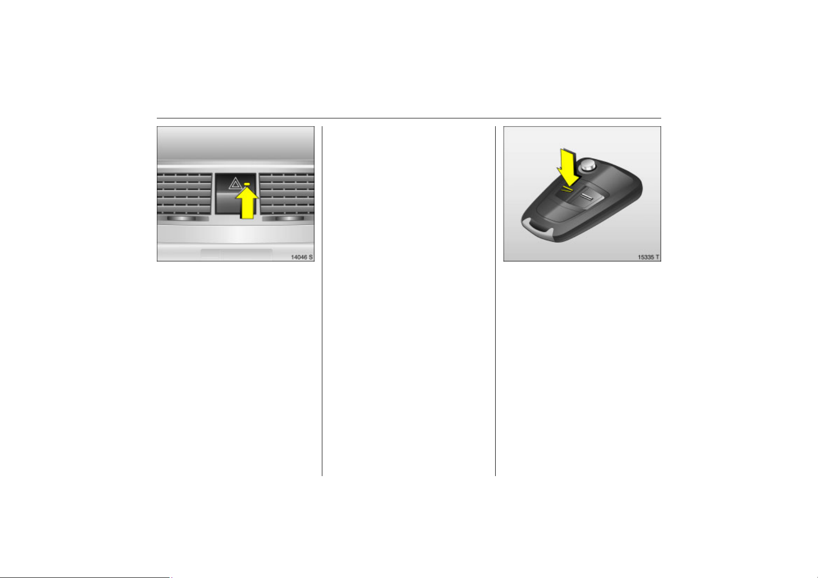
To lock
Picture no: 15333t.tif
Press button p on radio remote control.
Page 40
34 Keys, doors, windows, slide and tilt sunroof
Back to overview
Anti-theft alarm system 3
Monitors
z the doors, luggage compartment,
bonnet.
z the passenger compartment.
z vehicle tilt, e.g. if it is raised.
z the ignition.
9 Warning
Do not use the system if there are people
in the vehicle! The doors cannot be
unlocked from the inside.
Picture no: 15334t.tif
To activate
All doors, windows, sun roof 3, tilting
roof 3 and bonnet must be closed. Press
button p on the radio remote control
again within 10 seconds of locking.
If the ignition was switched on, the driver’s
door must be opened and closed once so
that the anti-theft alarm system can be
switched on.
Activation without monitoring of
Picture no: 11575s.tif
passenger compartment and vehicle tilt
Switch on e.g. if animals are to be left in the
vehicle.
1. Close tailgate and bonnet.
2. Press button in front of the courtesy lamp
(with ignition off); LED in the hazard
warning lamp button flashes a
maximum of 10 seconds.
3. Close doors.
4. Activate the anti-theft alarm system. The
LED lights up. After approx. 10 seconds,
the system is activated. The LED flashes
until the system is deactivated.
Page 41
After the first 10 seconds of anti-theft
Back to overview
alarm system activation:
z LED flashes
slowly
z LED comes on for
approx. 1 second
Contact a workshop for assistance if
problems are encountered.
=System switched on,
= Switch-off function.
35Keys, doors, windows, slide and tilt sunroof
Light emitting diode (LED)
Picture no: 14046s.tif
During the first 10 seconds of anti-theft
alarm system activation:
z LED comes on
z LED flashes
rapidly
= Test, delayed
switch-on,
= Door, tailgate or
bonnet open, or
system fault.
To deactivate
Picture no: 15335t.tif
Press button q on remote control unit
– or –
switch on ignition.
In the case of a malfunction in the remote
control, use the key to unlock the vehicle
3 32.
If the alarm is triggered when the driver’s
door is opened, deactivate the anti-theft
alarm system by switching on the ignition.
Page 42
36 Keys, doors, windows, slide and tilt sunroof
Back to overview
Note
z Changes to the vehicle interior, such as
the use of seat covers, could impair the
function of passenger compartment
monitoring.
z Switch off the interior monitoring system
when the interior of a parked vehicle is
being heated.
Alarm
When triggered, the alarm gives off an
acoustic signal (horn) and a visual signal
(hazard warning flashers). The number
and duration of the alarms are stipulated
by legislation.
The alarm can be silenced by pressing a
button on the remote control or by
switching on the ignition. The anti-theft
alarm system is deactivated at the same
time.
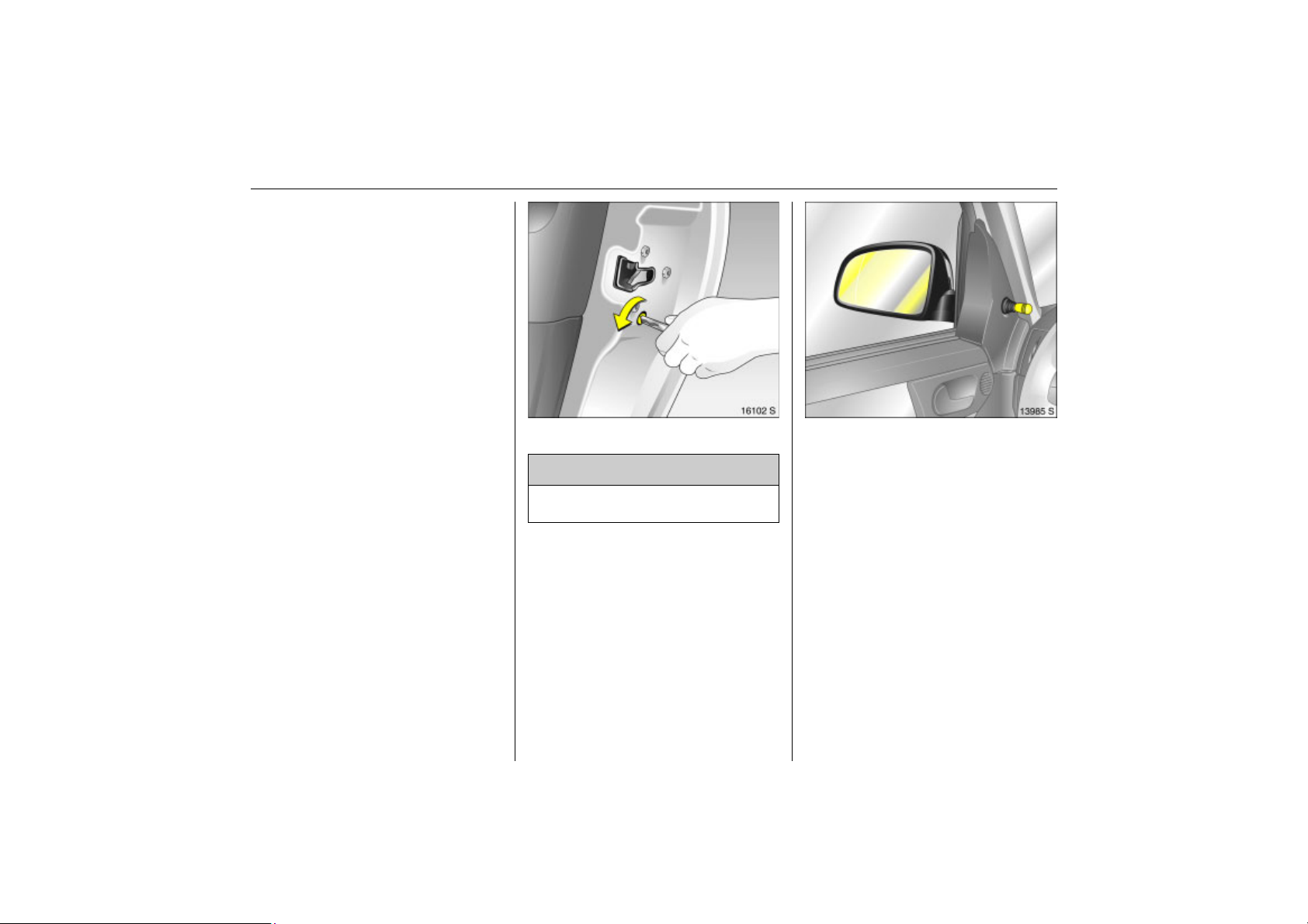
Child safety locks
Use the child safety lock whenever
children are occupying the rear seats.
Turn rotary knob at rear door lock from
vertical position using key: door cannot be
opened from the inside.
Picture no: 16102s.tif
9 Warning
Picture no: 13985s.tif
Exterior mirrors
Adjust manually with the handles in the
front door or electrically 3 with the switch
in the driver’s door console.
Adjust exterior mirrors manually
Use the knob to move the exterior mirrors in
the appropriate direction.
Page 43

37Keys, doors, windows, slide and tilt sunroof
Back to overview
Adjust exterior mirrors electrically 3
Picture no: 16099s.tif
Select the mirror to be adjusted using the
rocker switch and adjust using the fourway switch.
Aspherical exterior mirror 3
The aspherical mirror glass makes the blind
angle smaller. The curvature makes objects
look smaller, making it more difficult to
estimate how far away following vehicles
are.
To retract exterior mirrors
Picture no: 15279s.tif
Manual: The exterior mirrors can be folded
in by a slight pressure on the outer edge of
the housing.
Electric 3: Press button and both exterior
mirrors fold in.
Press button again and both exterior
mirrors swivel back to the driving position.
If a mirror has been manually adjusted,
swivel in both mirrors by hand and then
press the button.
After electrical operation, there is a
6 second delay before it can be swung
again.
For the safety of pedestrians, the exterior
Picture no: 14138s.tif
mirrors will swing out of their normal
mounting position if they are bumped with
sufficient force. Reposition the mirror by
applying slight pressure to the mirror
housing.
Page 44
38 Keys, doors, windows, slide and tilt sunroof
Back to overview
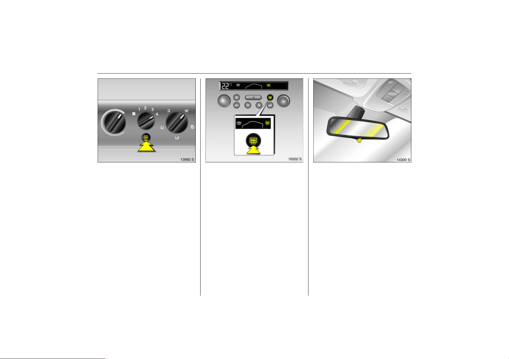
Heated exterior mirrors 3
Picture no: 13992s.tif
Heating is activated or deactivated by
pressing the Ü button.
On vehicles with electronic climate control
Picture no: 16502s.tif
Ü appears on the climate control display.
Heating works with the engine running and
is switched off automatically after a few
minutes.
Picture no: 14300s.tif
Interior mirror
Swivel mirror housing to adjust.
Manual anti-dazzle interior mirror
To reduce dazzle, swivel the lever on the
underside of the mirror housing.
Page 45
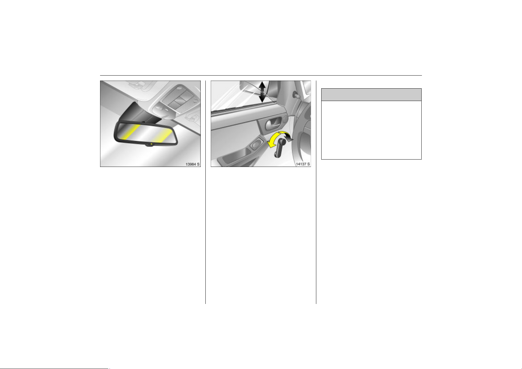
Automatic:Anti-dazzle interior mirror 3
Back to overview
Picture no: 13984s.tif
Dazzling at night is reduced automatically.
The interior mirror does not reduce dazzle
when:
z the ignition is switched off.
z reverse gear is engaged or selector lever
set to R.
z interior lighting has been switched on.
Picture no: 14137s.tif
Manual window operation
The door windows can be operated using
window winders.
39Keys, doors, windows, slide and tilt sunroof
Electric windows 3
9 Warning
Take care when operating the electric
windows. Risk of injury, particularly to
children.
If there are children on the rear seat,
switch on the child safety system 3 for
the electric windows.
Keep a close watch on the windows
when closing them. Ensure that nothing
becomes trapped in them as they move.
Operational readiness
Operable when the ignition key is in
position 1.
Button illumination indicates operational
readiness.
Operational readiness ends when the
driver’s door is opened.
Page 46
40 Keys, doors, windows, slide and tilt sunroof
Back to overview
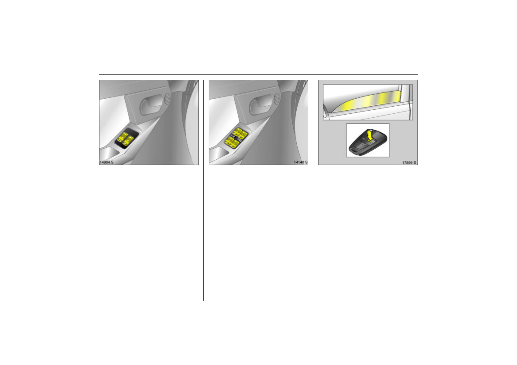
Operation
Picture no: 14804s.tif
To operate window in stages, tap
appropriate switch. For automatic opening
or closing, keep switch pressed for slightly
longer; to stop window movement, tap
switch again.
Safety function
If the window glass encounters resistance
above the middle of the window during
automatic closing, it is immediately
stopped and the window opened again.
If the windows do not move easily (e.g. on
account of frost), repeatedly tap the switch
for the window in question until the window
has been closed in stages.
Child safety system for rear windows 3
Picture no: 14140s.tif
Switch between the rocker switches in the
handle on the driver’s door
z to left (red control indicator visible): rear
windows cannot be operated with the
rocker buttons in the rear doors,
z to right (green control indicator visible):
rear windows can be operated with the
rocker buttons in the rear doors.
Closing windows 3 from outside
Picture no: 17899s.tif
On vehicles with electric windows in all
doors, the windows can be closed from
outside:
Hold button p of the remote control
depressed until all of the windows have
closed completely.
Page 47
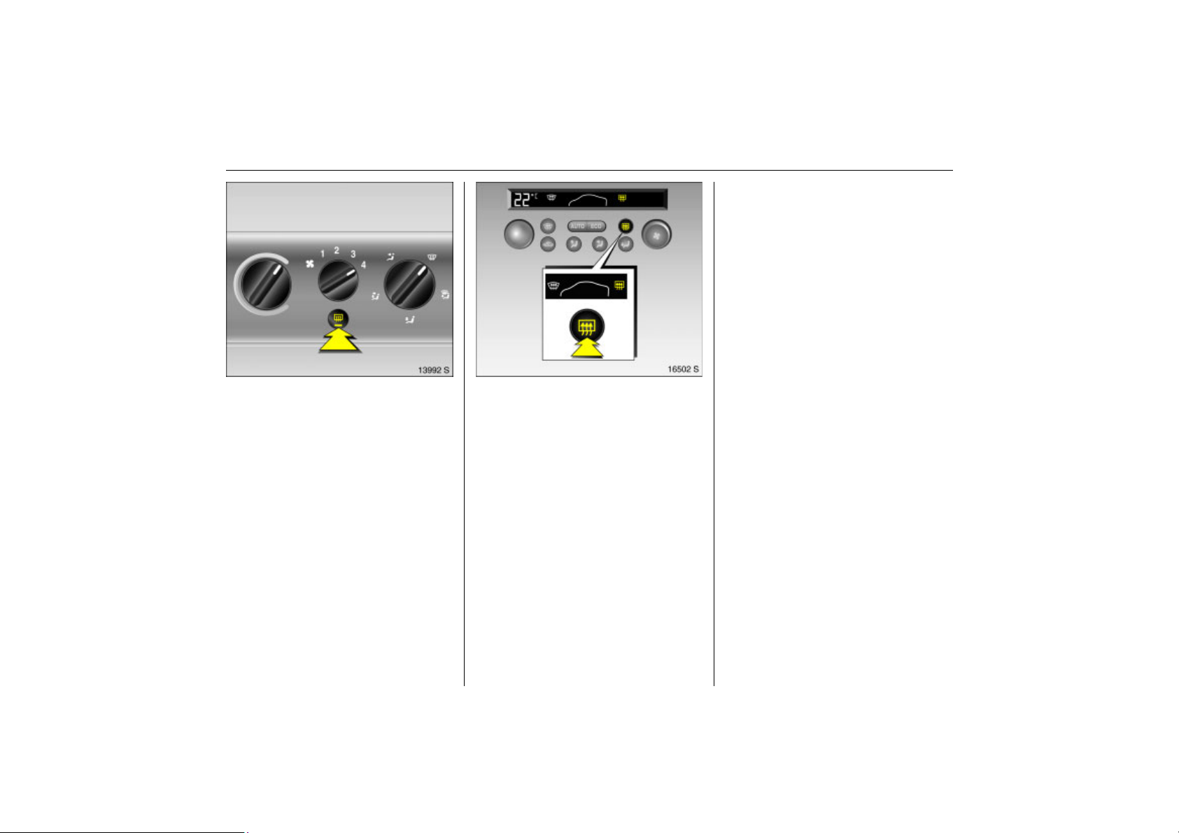
Heated rear window 3
Back to overview
Picture no: 13992s.tif
Heating is activated or deactivated by
pressing the Ü button.
On vehicles with electronic climate
Picture no: 16502s.tif
control Ü appears on the climate control
display.
Heating works with the engine running and
is switched off automatically after a few
minutes.
The heated rear window automatically
switches on when the diesel particle filter is
being cleaned 3 depending on the engine.
Climate control 3 114.
41Keys, doors, windows, slide and tilt sunroof
Overload
If the windows are repeatedly operated at
short intervals, the power supply is briefly
cut off.
Fault
If the windows cannot be opened and
closed automatically, activate the window
electronics as follows:
1. Close doors.
2. Switch on ignition.
3. Close the window completely and hold
the rocker switch down at least
5 seconds longer.
4. Open the window completely and hold
the rocker switch down at least 1 second
longer.
5. Repeat for each window.
Page 48
42 Keys, doors, windows, slide and tilt sunroof
Back to overview
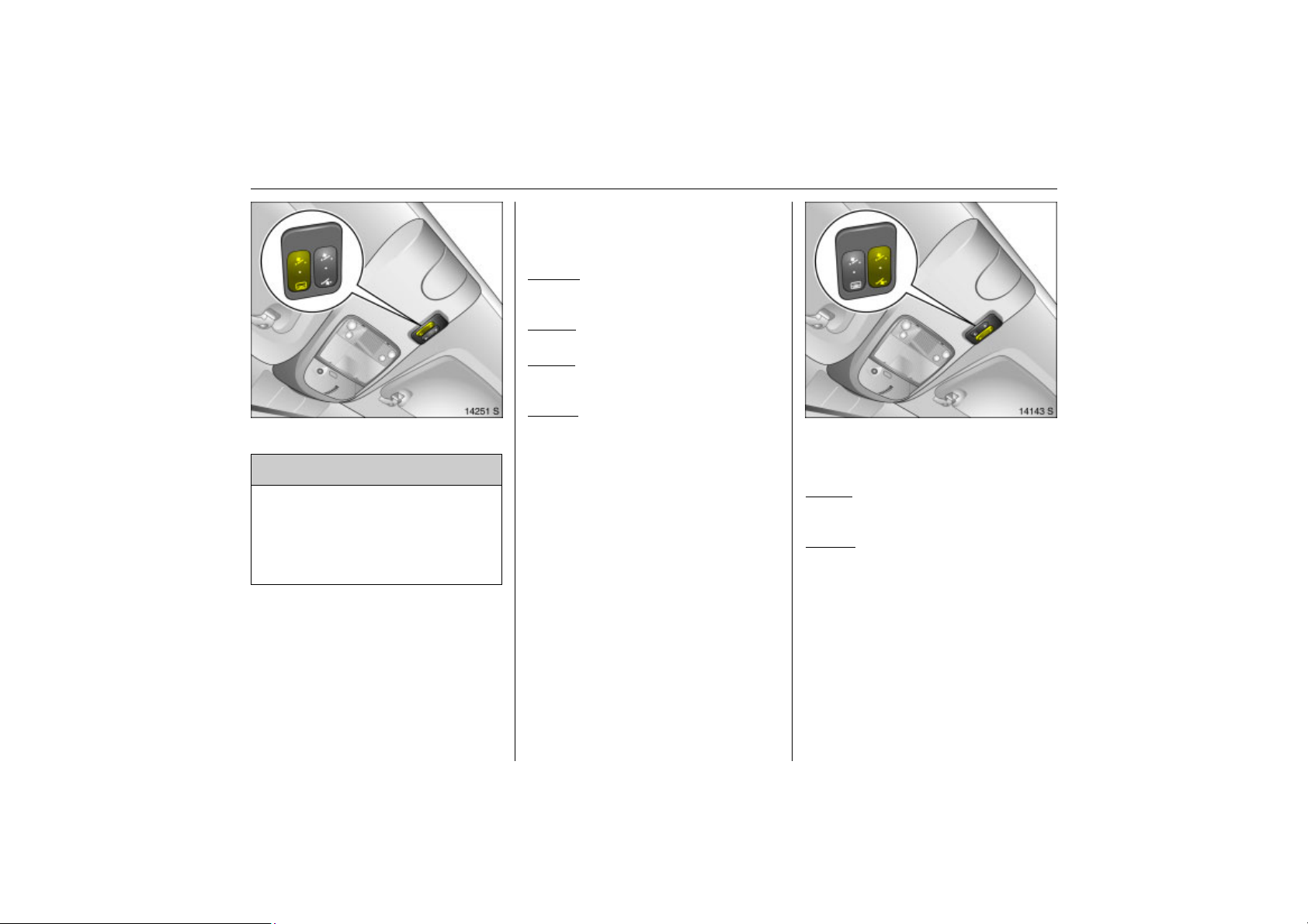
Front roof (sliding sun roof)
Left rocker switch l and \ between the
sun visors. Operable when the ignition is
on.
To open:
Press button I, sun roof opens. To stop
the movement, press button again.
Picture no: 14251s.tif
To close
Press button \ until the sun roof is closed.
To raise
With the sun roof closed, press button \
until sun roof is open.
To lower
Press button l until the sun roof is closed.
Sun roof and tilting roof 3
9 Warning
Take care when operating the sunroof 3
and the slide/tilt roof 3. Risk of injury,
especially for children.
Keep a close watch on the sun roof when
it is being closed. Ensure that nothing
becomes trapped.
Rear roof (tilting sun roof)
Picture no: 14143s.tif
Right rocker switch \ and w between the
sun visors. Operable with the ignition is on.
To raise
Press button \ until tilting roof has been
raised.
To lower
Press button w until tilting roof has closed.
Page 49
Sun shade
Back to overview
To reduce the sunlight in the interior with
the sliding roof closed or raised.
Open or close sun shade as required.
When the sun roof is opened, the sun shade
is also opened.
Note
z If the top of the roof is wet, raise roof,
allow water to run off and then open
roof.
z When using a roof rack, check the
clearance of the sun roof to avoid
damage.
Fault
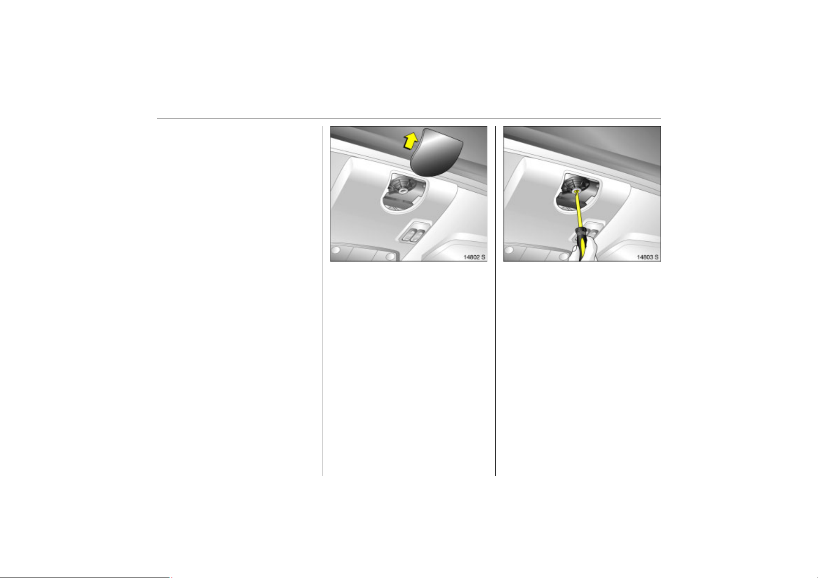
Picture no: 14802s.tif
If the electric drive fails, the system is
protected by a fuse in the fuse box 3 181.
Until the fault is remedied, operate the sun
roof as follows:
Push drive cover backwards.
43Keys, doors, windows, slide and tilt sunroof
Picture no: 14803s.tif
Use a screwdriver 3 to push the drive shaft
in and turn until the sunroof or slide/tilt roof
is closed.
Page 50
44 Seats, Interior
Back to overview
Seats, Interior
Front seats ........................................... 44
Head restraints .................................... 46
Armrest 3 ............................................. 48
Travel Assistant 3 ............................... 48
Rear seats............................................. 51
Flexible Seat System (FlexSpace) ....... 52
Luggage compartment extension ..... 53
Luggage compartment cover 3......... 55
Safety net 3 ......................................... 56
Lashing eyes ........................................ 57
Bag hangers 3..................................... 57
Notes on loading the vehicle.............. 58
Three-stage safety system.................. 59
Three-point seat belts ......................... 59
Belt tensioners...................................... 60
Using the belts ..................................... 62
Mounting clips 3 for ISOFIX child
restraint systems ............................... 64
Child restraint system 3 ...................... 65
Airbag system...................................... 67
Cigarette lighter 3............................... 78
Accessory sockets 3 ............................ 78
Ashtrays ............................................... 79
Stowage compartments...................... 80
Foldaway tables 3 .............................. 81
Coin holder 3 ....................................... 81
Sun visors.............................................. 81
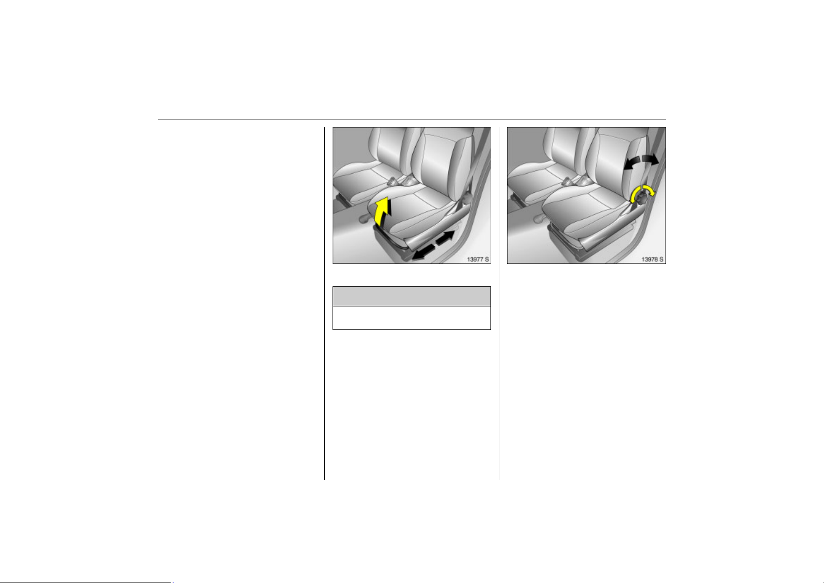
Picture no: 13977s.tif
Front seats
9 Warning
Never adjust seats while driving. They
may make uncontrolled movements.
Adjust longitudinal seat position
Pull handle at front of seat, move seat and
then release handle.
Adjusting the backrests
Picture no: 13978s.tif
Take the pressure off the backrest and turn
the hand wheel on the side.
Page 51
45Seats, Interior
Back to overview
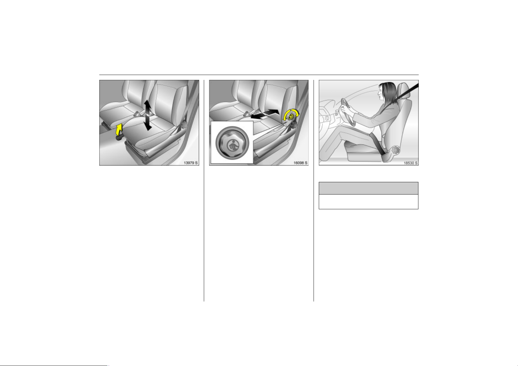
Adjusting the seat height 3
Picture no: 13979s.tif
Lift front side lever and relieve some weight
from seat to raise it or press down on seat
with body weight to lower it.
Adjusting the lumbar support 3
Picture no: 16098s.tif
Turn side hand wheel on backrest while
relieving the load on the backrest.
Seat position
Picture no: 18530s.tif
9 Warning
Only drive with the seat correctly
adjusted.
z Sit with your buttocks as far back against
the backrest as possible. Adjust the
distance between your feet and the
pedals so that your legs are slightly
angled when pressing the pedals. Slide
the passenger seat as far back as
possible.
Page 52
46 Seats, Interior
Back to overview
z Sit with your shoulders as far back
against the backrest as possible. Set the
backrest rake so that you can easily
reach the steering wheel with your arms
slightly bent. Maintain contact between
your shoulders and the backrest when
turning the steering wheel. Do not angle
the backrest too far back. We
recommend a maximum rake of
approx. 25.
z Adjust the steering wheel 3 5.
z Set seat height 3 high enough to have a
clear field of vision on all sides and of all
display instruments. There should be at
least six inches of clearance between
your head and the headlining. Your
thighs should rest lightly on the seat
without pressing into it.
z Adjust the head restraint.
z Adjust the height of the seat belt 3 62.
z Adjust the lumbar support 3 so that it
supports the natural shape of the spine.
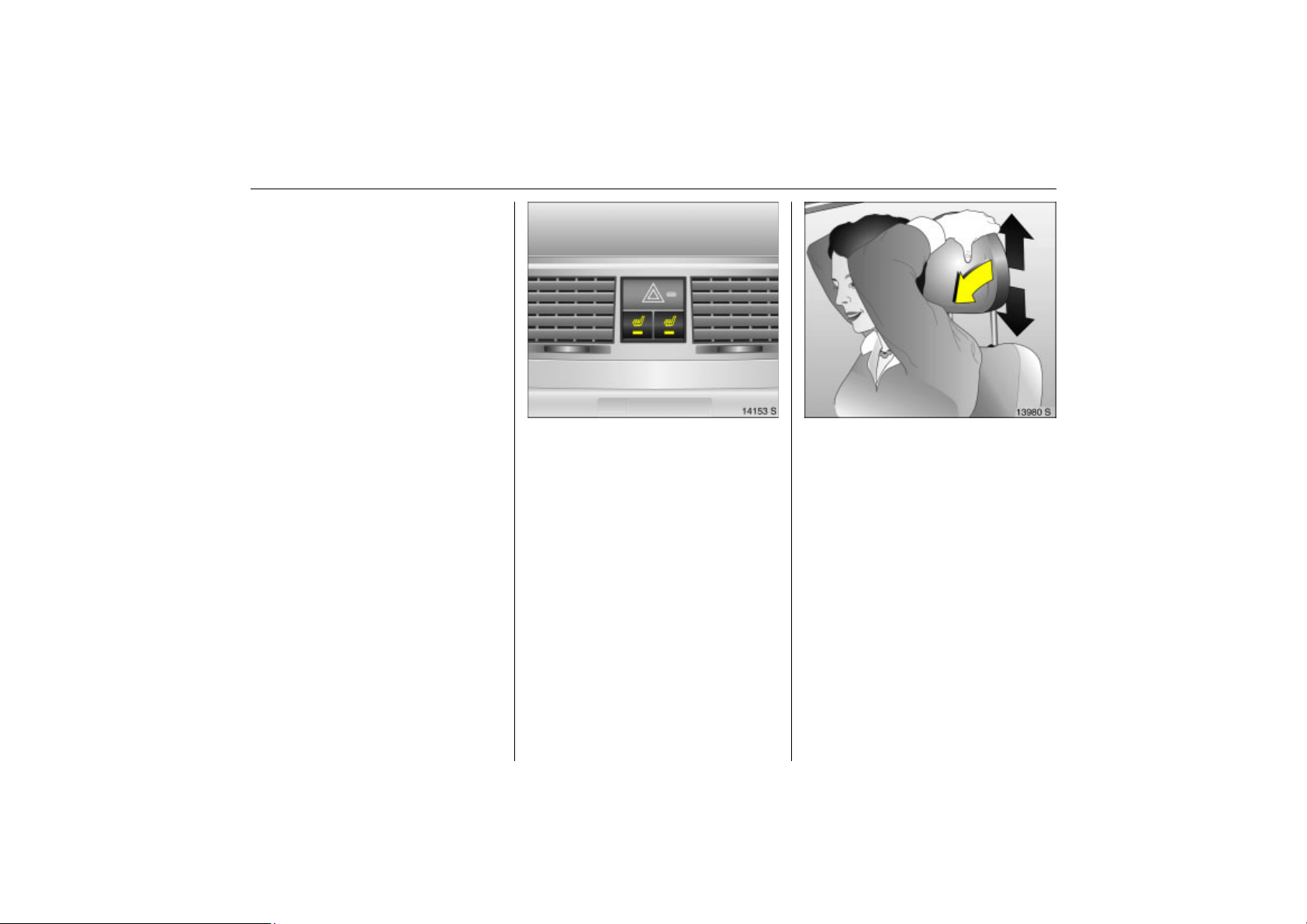
Heated front seats 3
Picture no: 14153s.tif
Two buttons between the centre air vents
for the left and right seats.
To heat with the ignition switched on, press
button ß.
Picture no: 13980s.tif
Head restraints
Adjusting the front head restraints and
the rear outboard head restraints 3
Tip head restraint forward, hold and adjust
height.
To fold over the rear seats or lower the
front passenger seat head restraint all the
way down and remove, see next page.
With the seats occupied, adjust height
according to body size.
Page 53
47Seats, Interior
Back to overview
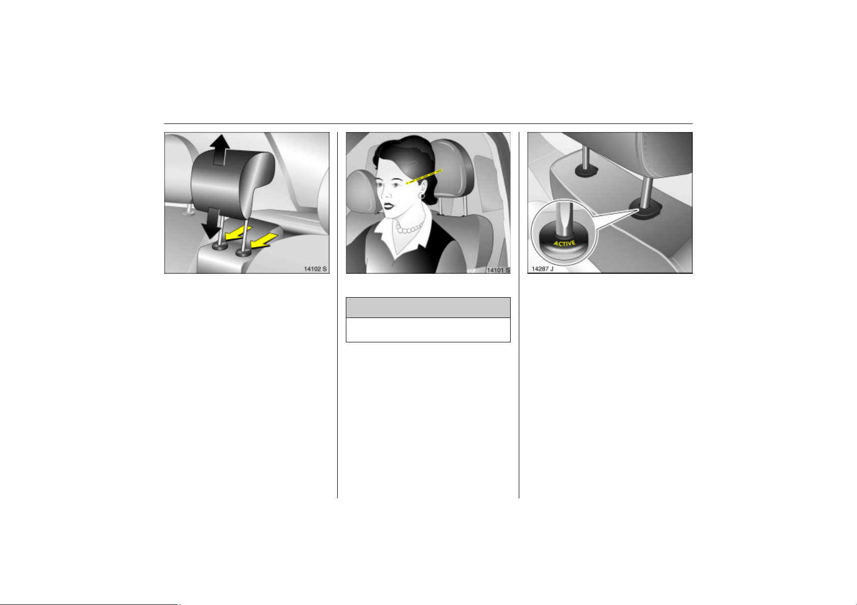
Adjusting the rear centre head restraint
Picture no: 14102s.tif
Pull head restraint upwards, press springs
and push head restraint down.
To improve visibility push headrest down
as far as possible if middle seat is
unoccupied or to increase the size of the
luggage compartment.
Fold down centre seat 3 54.
If centre seat is occupied, pull head
restraint upwards.
Head restraint position
Picture no: 14101s.tif
9 Warning
Only drive with the head restraint set to
the proper position.
The middle of the head restraint should be
at eye level. If this is not possible for
extremely tall persons, set to highest
position, and set to lowest position for
small persons.
Active head restraints 3 on front seats
Picture no: 14287j.tif
In the event of a rear-end impact, the
active head restraints automatically tilt
slightly forward. The head is more
effectively supported by the head restraint
and the danger of injury in the area of the
cervical vertebra is reduced.
Active head restraints can be recognised
by the word ACTIVE.
Page 54
48 Seats, Interior
Back to overview
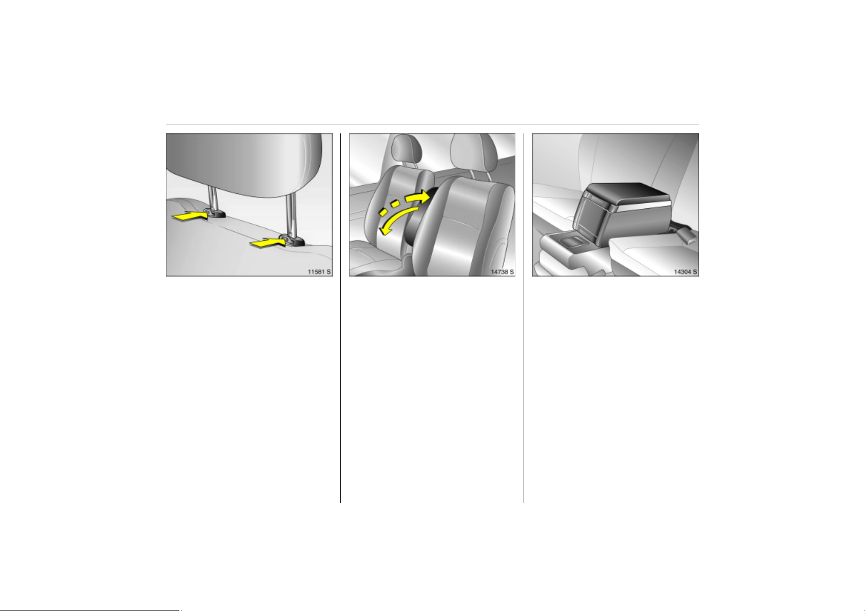
Removing
Picture no: 11581s.tif
Press and release the two catches. Pull and
remove the head restraint.
To fold down the rear seat backrests 3
3 53, push rear head restraints fully down.
Note
Only approved objects or components
must be attached to the head restraint of
the unoccupied front passenger seat.
Picture no: 14738s.tif
Armrest 3
Armrest at driver’s seat
Push raised armrest backward against
resistance and fold down.
The armrest can be moved to different
positions in stages by lifting it.
If the armrest is not required, it can be
folded up.
Armrest 3 between rear seats
See "Travel Assistant, armrest" 3 49.
Picture no: 14304s.tif
Travel Assistant 3
The Travel Assistant Contains
z Armrest,
z Tray,
z Drink holders.
The Travel Assistant is mounted on the
lowered centre seat 3 54.
Page 55
49Seats, Interior
Back to overview
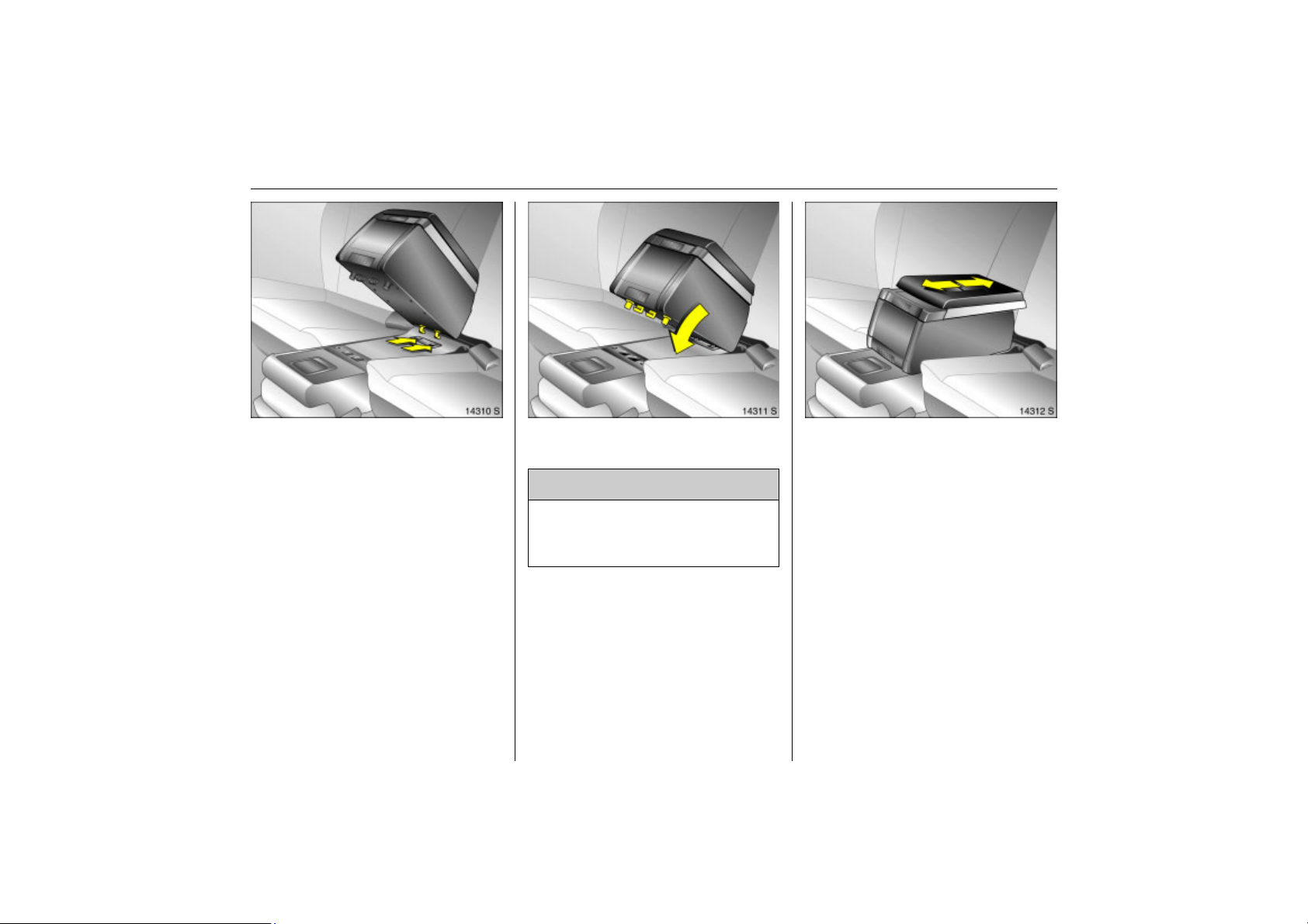
Installing The Travel Assistant
Picture no: 14310s.tif
Lower centre seat 3 54.
Insert Travel Assistant in rear recesses on
back of middle seat.
Fold Travel Assistant down and audibly
Picture no: 14311s.tif
engage in front recesses.
9 Warning
If it is not correctly engaged, the Travel
Assistant can be propelled forward with
considerable force if hard braking
occurs, possibly causing injury.
Armrest
Picture no: 14312s.tif
The arm rest can be moved and therefore
adapted to the position of the outboard
seats.
Page 56
50 Seats, Interior
Back to overview
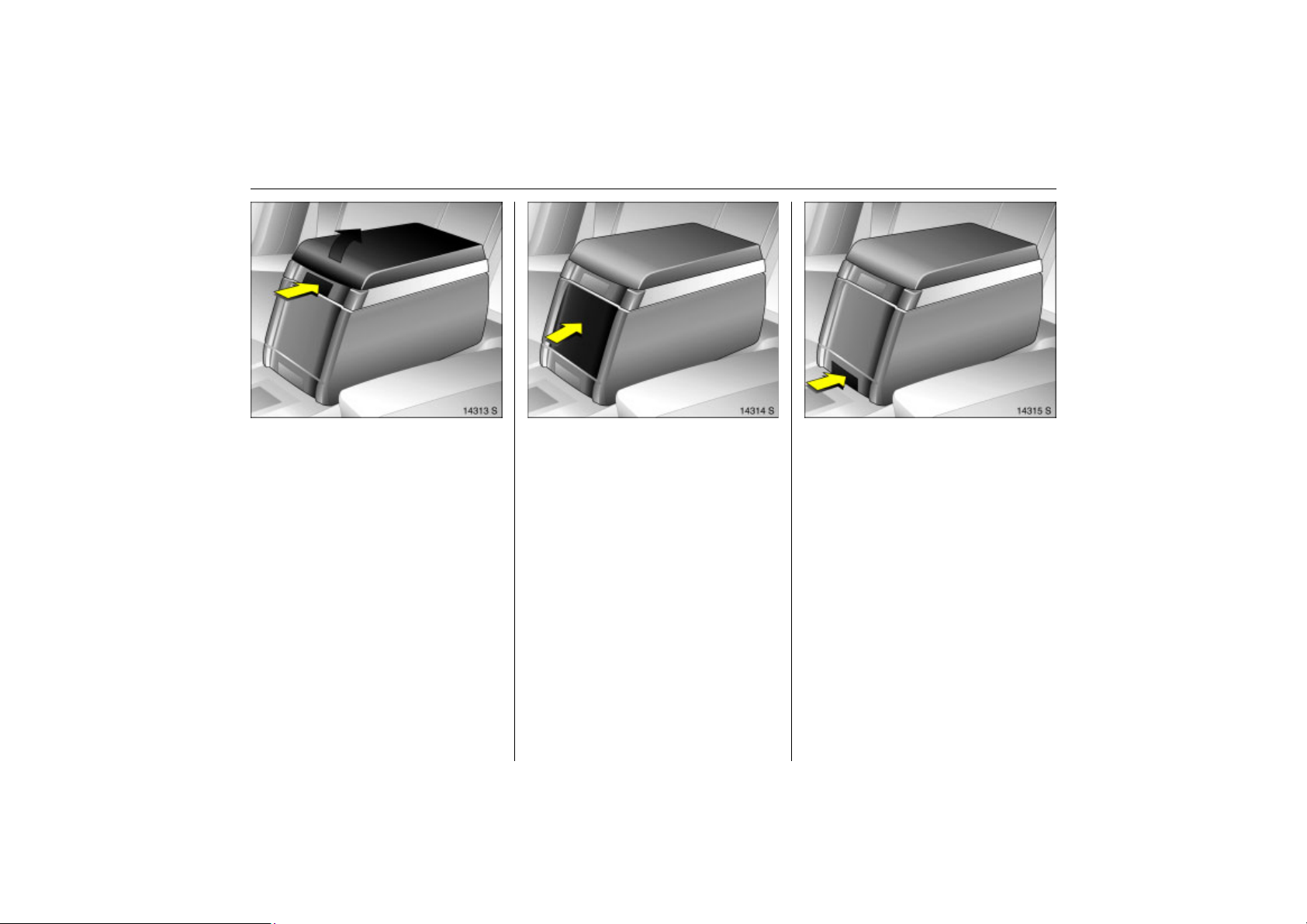
Tray
Picture no: 14313s.tif
There is a tray beneath the armrest. Open
tray by pushing upper button.
Drink holder
Picture no: 14314s.tif
Open drink holder on front by pressing
front face.
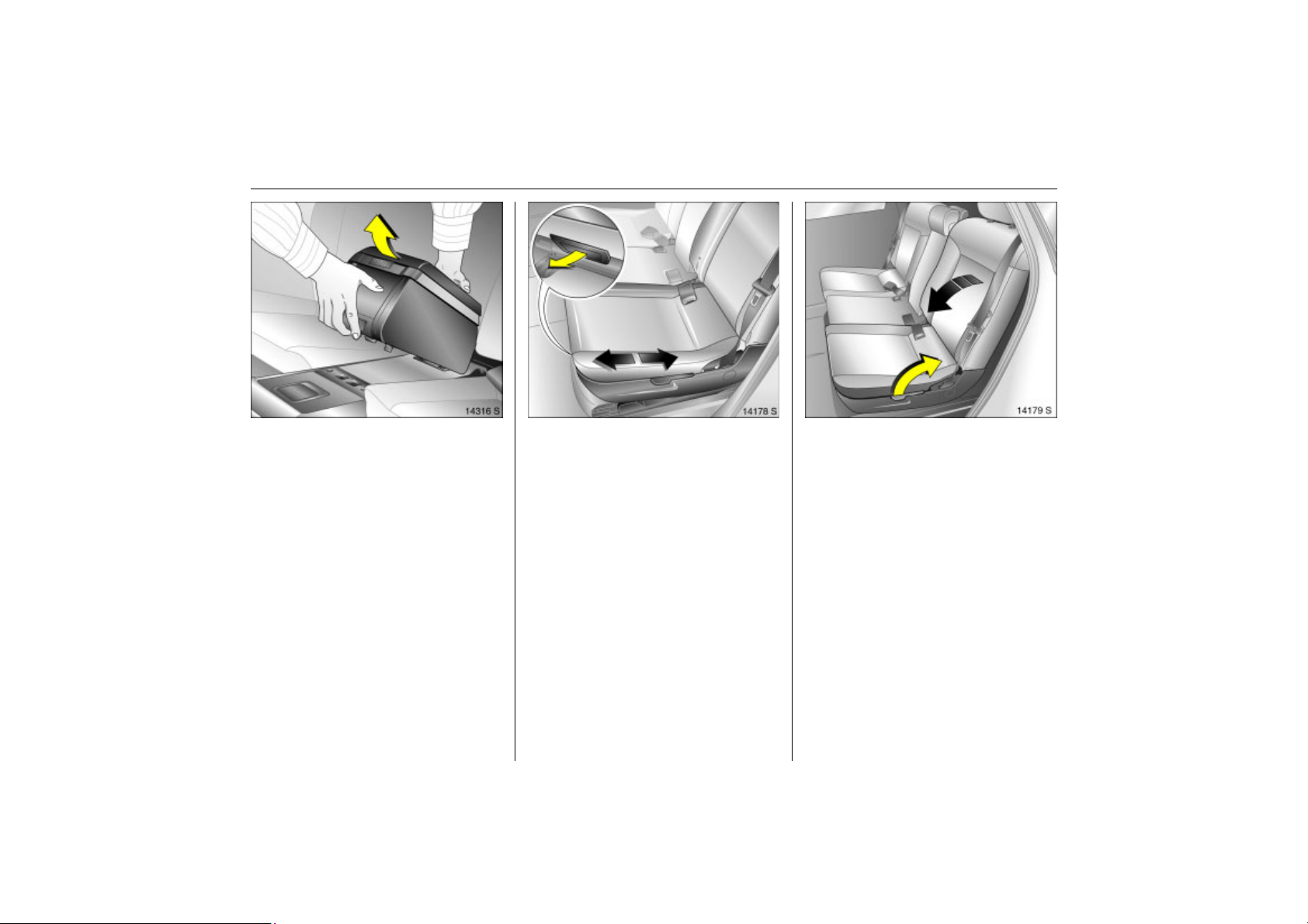
Dismantling the Travel Assistant
Picture no: 14315s.tif
Press lower button on the Travel Assistant.
Page 57
51Seats, Interior
Back to overview
Pull Travel Assistant upwards out of
Picture no: 14316s.tif
recesses.
There is a carrying handle on the back to
facilitate transport.
It is not necessary to remove the Travel
Assistant if you wish to raise the centre
seat, however, the armrest must be pushed
forwards. Be careful of any items in the
Travel Assistant.
Picture no: 14178s.tif
Rear seats
Sliding outboard rear seats front-rear
The rear outboard seats can be
individually adjusted front-rear.
Pull handle under seat, move seat, release
handle and allow seat to engage.
When pushing the seats back, to prevent
damage make sure the backrests are not in
their furthest back position.
Adjust backrest rake of rear outboard
Picture no: 14179s.tif
seats
Grasp backrest, pull handle at outboard
side of seat and guide backrest, unloaded,
into the required position. Release handle
and allow backrest to engage.
The backrest rake can be set in three
positions.
Page 58
52 Seats, Interior
Back to overview
9 Warning
To prevent injuries, always hold back
seat backrest firmly and guide
downward when folding.
To achieve a flat loading surface in the
extended luggage compartment, the
outboard seats can be lowered slightly. We
recommend however only using the seats
as seats in the raised position. Extending
the luggage compartment 3 53.
Flexible Seat System (FlexSpace)
The rear seat row on the Meriva can be
fitted with three seats in Variant 1, or two
seats with maximum seating space in
Variant 2. In Variant 2, the centre seat is
lowered.
The luggage compartment can only be
extended in Variant 1 3 53.
To extend the luggage compartment, the
outboard seats can be lowered slightly
3 54.
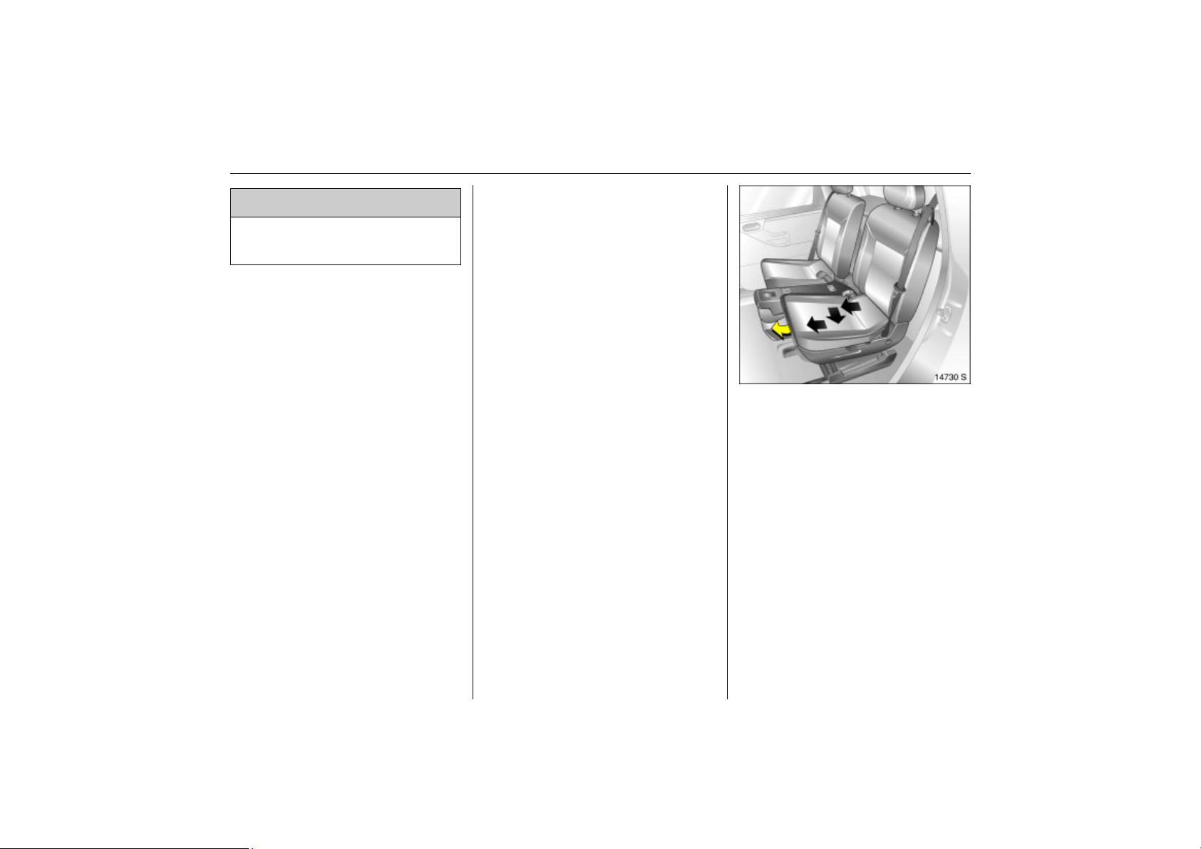
Picture no: 14730s.tif
Variant 1: Three rear seats
Set seat backrest to centre position using
the handle on the outside of the seat 3 51.
Pull the handle beneath the seat. Slide the
seat all the way forward, then outward
toward the door and then further forward
to the desired position.
Release handle and allow seat to engage
in position.
Raise centre seat 3 54.
Page 59
Luggage compartment extension
Back to overview
To increase the size of the luggage
compartment you can
z fold down the outboard rear seat
backrests,
z lower the middle seat,
z lower the folded outboard seats,
z fold down the passenger seat
backrest 3,
see following instructions.
The rear seats must also be in "Variant 1:
Three rear seats" 3 52.
53Seats, Interior
Variant 2: Two rear seats
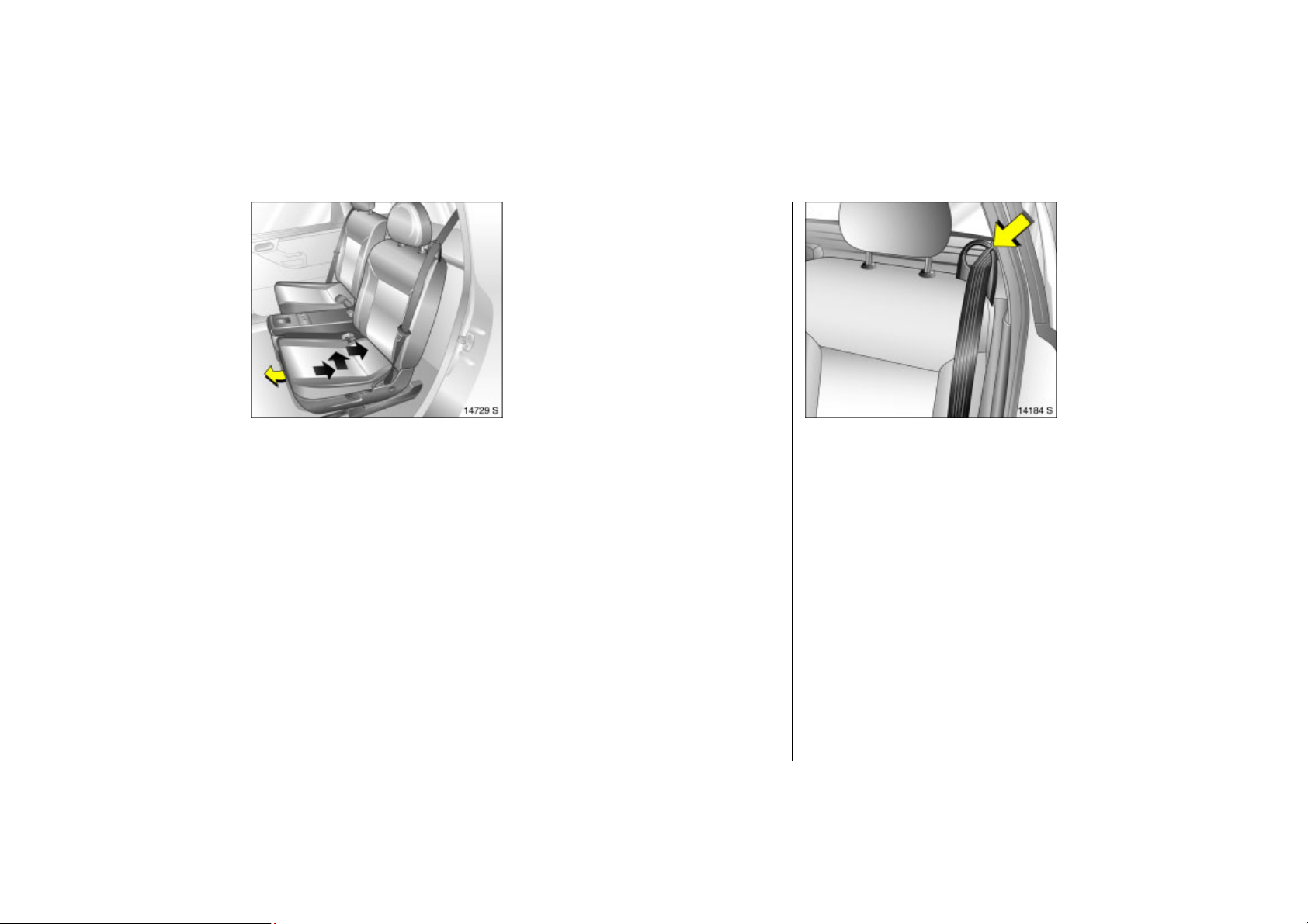
Picture no: 14729s.tif
Lower the centre seat by pulling the release
handle on the back of the centre seat
backrest, fold backrest forward and
engage 3 54.
Set seat backrest to centre position using
the handle on the outside of the seat 3 51.
Pull the handle beneath the seat. Slide the
seat all the way back, then inward toward
the middle of the vehicle, and then further
back to the desired position
Release handle and allow seat to engage
in position.
Fold down the outboard rear seat
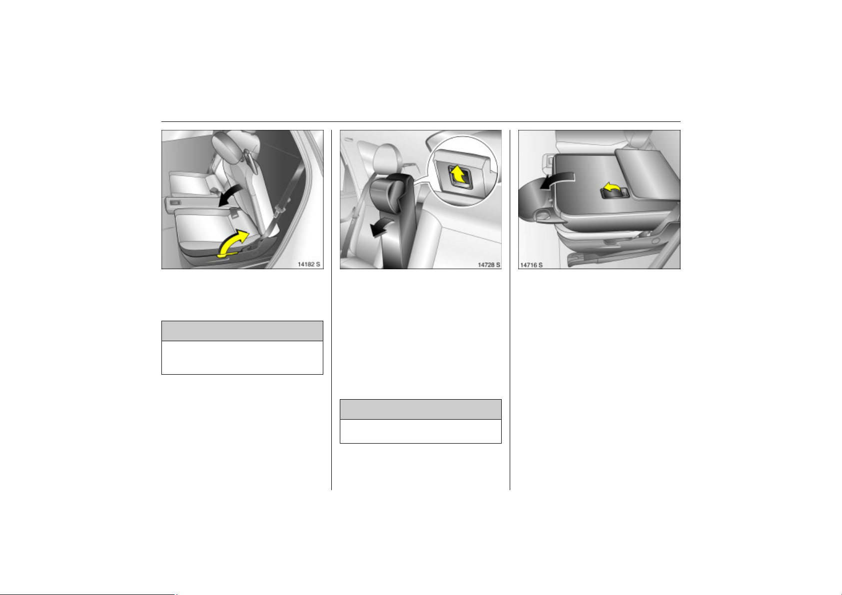
Picture no: 14184s.tif
backrests
Remove the luggage compartment
cover 3 if necessary 3 55.
Push head restraints down fully, 3 3, 3 46.
Take seat belt out of the belt guide on the
backrest.
Remove the push-in sleeves 3 for
mounting the ISO-FIX child restraint
system – see separate instructions for the
ISO-FIX child restraint system.
Page 60
54 Seats, Interior
Back to overview
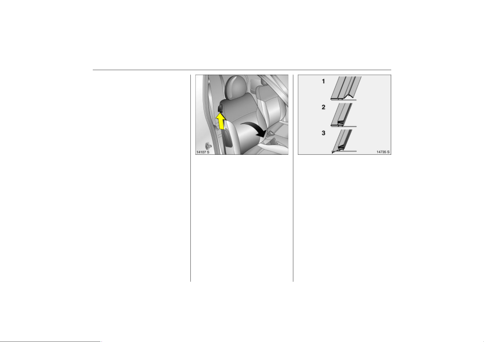
Grasp the backrest, pull the handle at the
Picture no: 14182s.tif
outboard side of the seat and fold the
backrest onto the seat. Release the handle
and engage the backrest.
9 Warning
To prevent injuries, always hold the seat
backrest firmly and guide downward
when folding.
To raise, pull the handle on the outboard
side of the seat and raise the backrest.
Release the handle and engage.
Insert the seat belt into the belt guide at
backrest.
Fold the centre seat forward and lower.
Picture no: 14728s.tif
House centre seat belt in the holder in the
ceiling 3 63.
Insert seat belts into recesses in seat
cushion.
Slide centre seat head rest all the way
down 3 47.
Pull release handle on the back of the
centre seat backrest, see figure. Fold
backrest forward and engage. The entire
seat is lowered.
9 Warning
The load must not hinder the operation
of the hand brake or gear lever 3 58.
Raise centre seat
Picture no: 14716s.tif
Pull release handle on the back of the
backrest, erect the backrest and engage,
the outer seats must be in the outer
position, see Variant 1: Three rear seats
3 52.
Lower outboard seats
Push front seat forward and fully lower or
remove head restraints on the rear
outboard seats 3 47.
Fold outer rear seat backrests onto seat
bases.
To achieve a level loading surface, pull
release handle on back of backrest and
push seat down until it latches into
position.
Page 61
Raise outboard seats
Back to overview
Pull release handle on back of backrest
and pull seat upward until it engages.
Pull handle on outboard side of rear seat
and move rear seat backrest upright.
Release handle and latch.
Insert the seat belt into the belt guide at
backrest.
The backrest can be raised to an upright
position even with the seat lowered. We
recommend however only using the seat as
a seat in the higher position.
55Seats, Interior
Fold down passenger seat backrest 3
Picture no: 14107S.tif
Push head restraint all the way down or
remove 3 3, 3 46.
Push front passenger seat back.
Lift release lever and fold front passenger
seat backrest down.
Raise front passenger seat backrest 3
Press release lever forward, restore
passenger seat backrest to upright
position and engage audibly.
Picture no: 14735S.tif
Luggage compartment cover 3
Do not place any heavy or sharp-edged
objects on the cover.
To open
Lift cover at rear and tilt forward segment
by segment.
To close
Tilt top part of cover backward and latch
into position.
Page 62
56 Seats, Interior
Back to overview
Removing
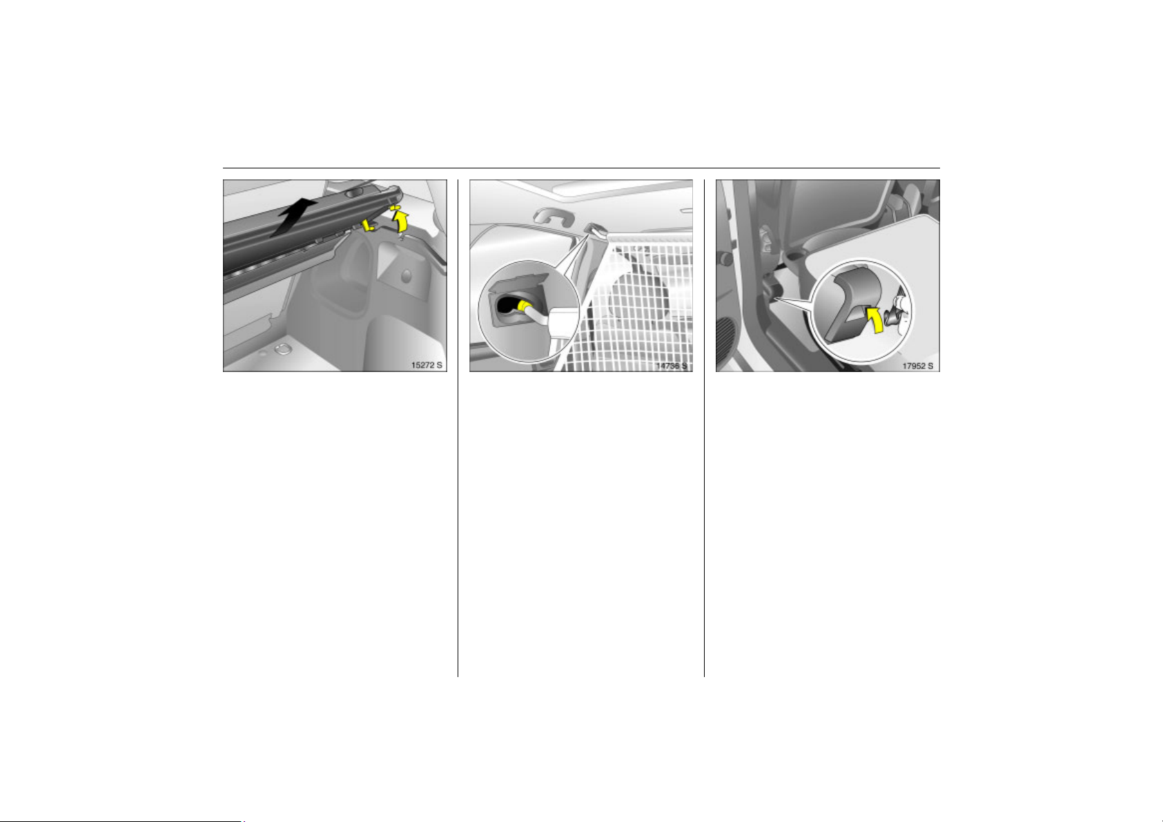
Picture no: 15272s.tif
Open cover, disengage toward the rear
and remove from above.
Fitting
Insert the cover from the rear, clip into
place and fold back.
Picture no: 14736s.tif
Safety net 3
The safety net can be mounted behind the
front seats. The rear seat backrests are
folded forward.
Passengers must not be carried behind the
safety net.
Fitting
The safety net is in the luggage
compartment below the floor covering, see
right-hand column.
Fold all rear seat backrests forward, see
Extending the luggage compartment 3 53.
The roof frame contains two mounting
openings: Open covers. Hang the upper
net rod first in one opening and then in the
other side; clip in place forwards.
Hook the net straps into slots on the outer
Picture no: 17952S.tif
seat bracket of the front seats and tighten.
When the safety net is fitted for the first
time, the slots on the outer seat consoles of
the front seats must be opened once: press
marked area on upper edge with a blunt
object and bend inward.
Removing
Tilt strap length adjuster upwards and
unhook straps at bottom. Unhook upper
net rod and close mounting openings.
Page 63
57Seats, Interior
Back to overview
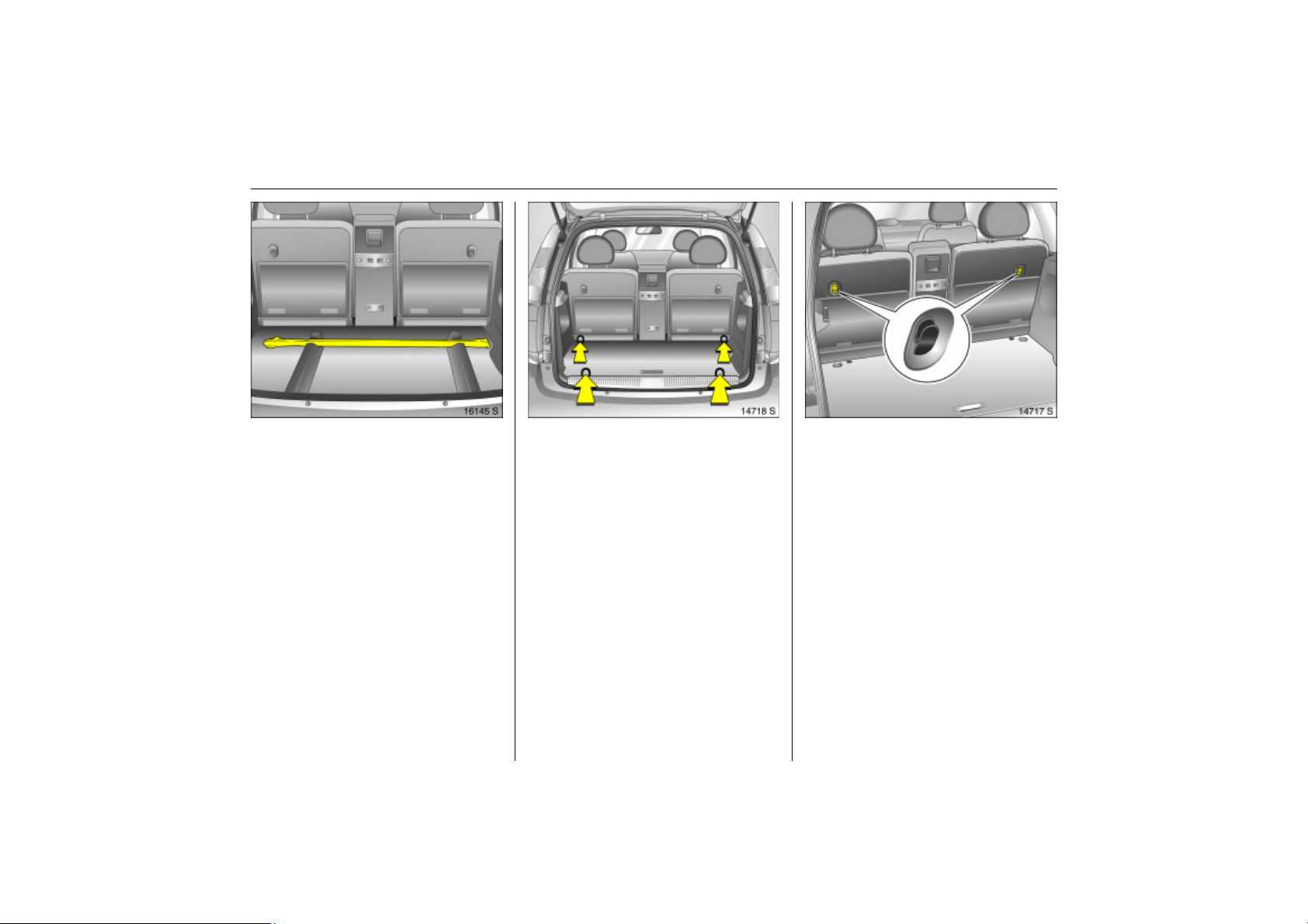
Stowage of safety net
Picture no: 16145s.tif
Roll up the removed safety net and secure
it with Velcro strip.
Store safety net in luggage compartment
below the floor covering. To open, remove
the luggage compartment cover 3 3 55,
lift floor covering at handle recess and tip
forward 3 171. Position safety net at the
front in the recesses.
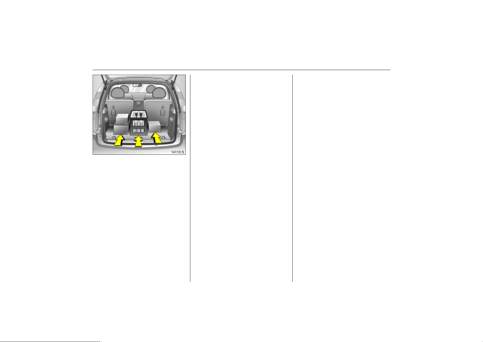
Picture no: 14718s.tif
Lashing eyes
Lashing eyes are provided to secure
objects against sliding B with straps 3 or
netting 3.
Picture no: 14717s.tif
Bag hangers 3
There are two retainers on the back of the
rear seat backrests for hanging carrier
bags on. Maximum load: 10 kg per
retainer.
Page 64
58 Seats, Interior
Back to overview
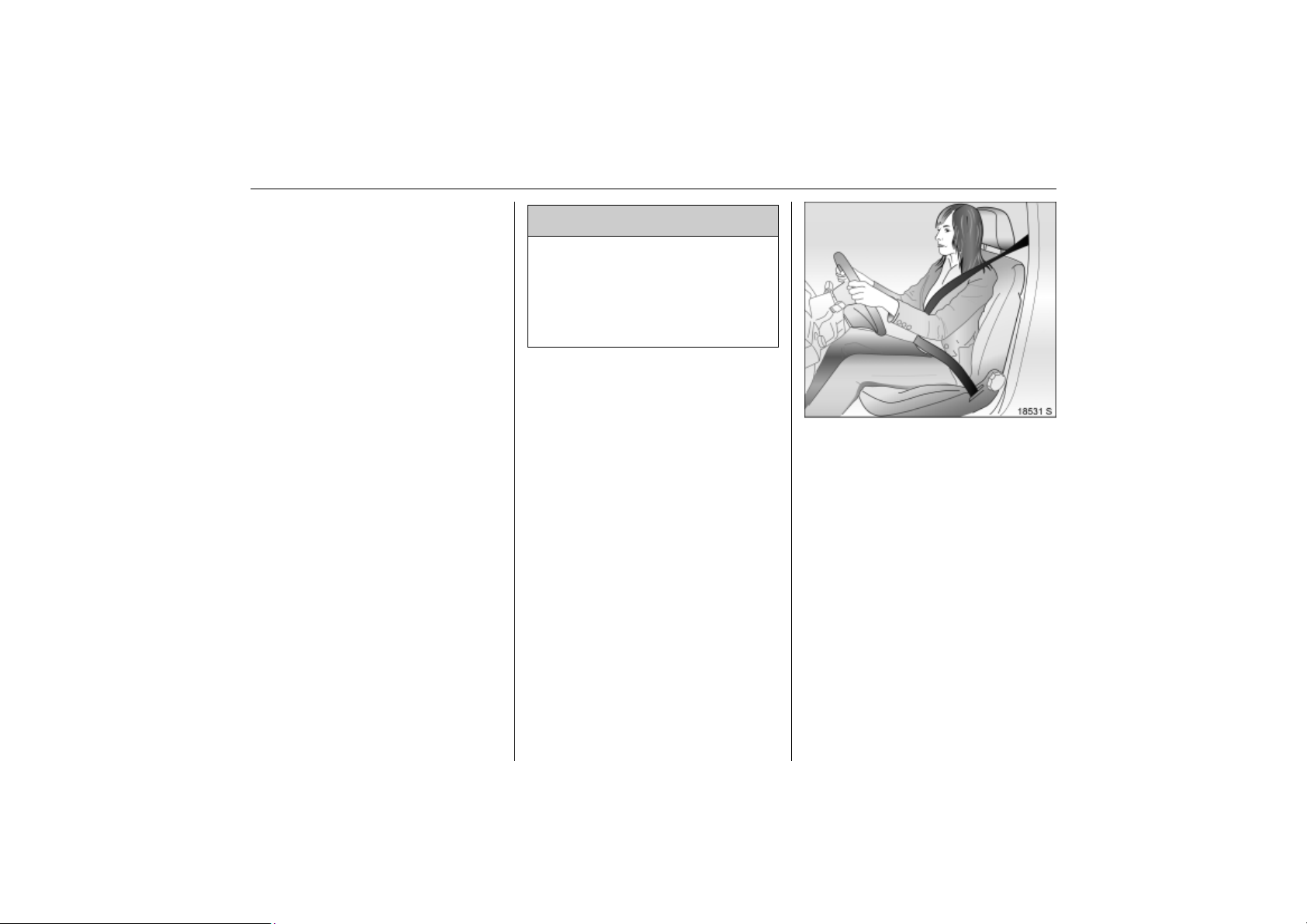
Picture no: 14110s.tif
Notes on loading the vehicle
z Heavy objects in the luggage
compartment should be placed as far
forward as possible against the properly
engaged rear seat backrests or, if the
rear seat backrests are folded down,
against the front seat backrests. If
objects are to be stacked, the heavier
objects should be placed at the bottom.
z Secure heavy objects with lashing
straps 3 attached to lashing eyes 3 57.
z When transporting objects with rear seat
backrests tilted forward, fit the safety net
3 56.
z Close luggage compartment cover 3
3 55.
z If the backrests are not folded down
when transporting objects in the
luggage compartment, they must be
engaged in an upright position 3 55.
z Do not allow the load to protrude above
the upper edge of the backrests.
z The warning triangle 3 and first-aid kit
(cushion) 3 must always be freely
accessible.
z Do not place any objects on the luggage
compartment cover 3 or the instrument
panel.
z No objects must be placed in the airbag
inflation area, since they could cause
injury when the systems are triggered.
z Items loaded must not prevent operation
of the pedals, hand brake and gears or
obstruct the freedom of movement of
the driver. Do not place loose objects in
the interior.
z Do not drive with luggage compartment
open when transporting bulky objects,
for example, since toxic exhaust fumes
could penetrate the interior.
z The payload is the difference between
the permitted gross vehicle weight (see
identification plate 3 218) and the EC
kerb weight.
z To calculate the EC kerb weight, enter
the data for your vehicle on page 3 226.
z The EC kerb weight includes allowances
for the driver (68 kg), luggage (7 kg) and
all fluids (tank 90 % full).
z Optional equipment and accessories
increase the kerb weight.
z Weights and loads 3 226.
z Driving with a roof load increases the
sensitivity of the vehicle to cross-winds
and has a detrimental effect on vehicle
handling due to the vehicle’s higher
centre of gravity. Distribute the load
evenly and secure it properly with
retaining straps. Adjust the tyre pressure
to the load conditions. Do not drive
faster than 120 km/h. Check and retighten the straps frequently. Observe
country-specific regulations.
z The permissible roof load is 100 kg. The
roof load consists of the weight of the
roof rack plus the load carried.
Page 65
59Seats, Interior
Back to overview
Three-stage safety system
Comprising:
z three-point seat belts,
z belt tensioners at the front seats,
z airbag systems for the driver and front
passenger seats 3 as well as the
outboard rear seats 3.
The three stages are activated in sequence
depending on the severity of the accident:
z The automatic seat belt locking devices
prevent the belt strap from being pulled
out and thus ensure that the vehicle
occupants are retained in their seats.
z The front seat belts are pulled down at
the belt buckles. This means the belts fit
snugly, the occupants are decelerated
early with the vehicle and the body
loading is reduced.
z The airbag systems are also triggered in
the event of severe accidents and form a
safety cushion for the occupants.
9 Warning
The airbag systems serve to supplement
the three-point seat belts and belt
tensioners. The seat belts must therefore
always be worn. Disregard of these
instructions may lead to injuries or
endanger life. Vehicle passengers
should be informed accordingly.
Read the instructions supplied with the
child restraint system
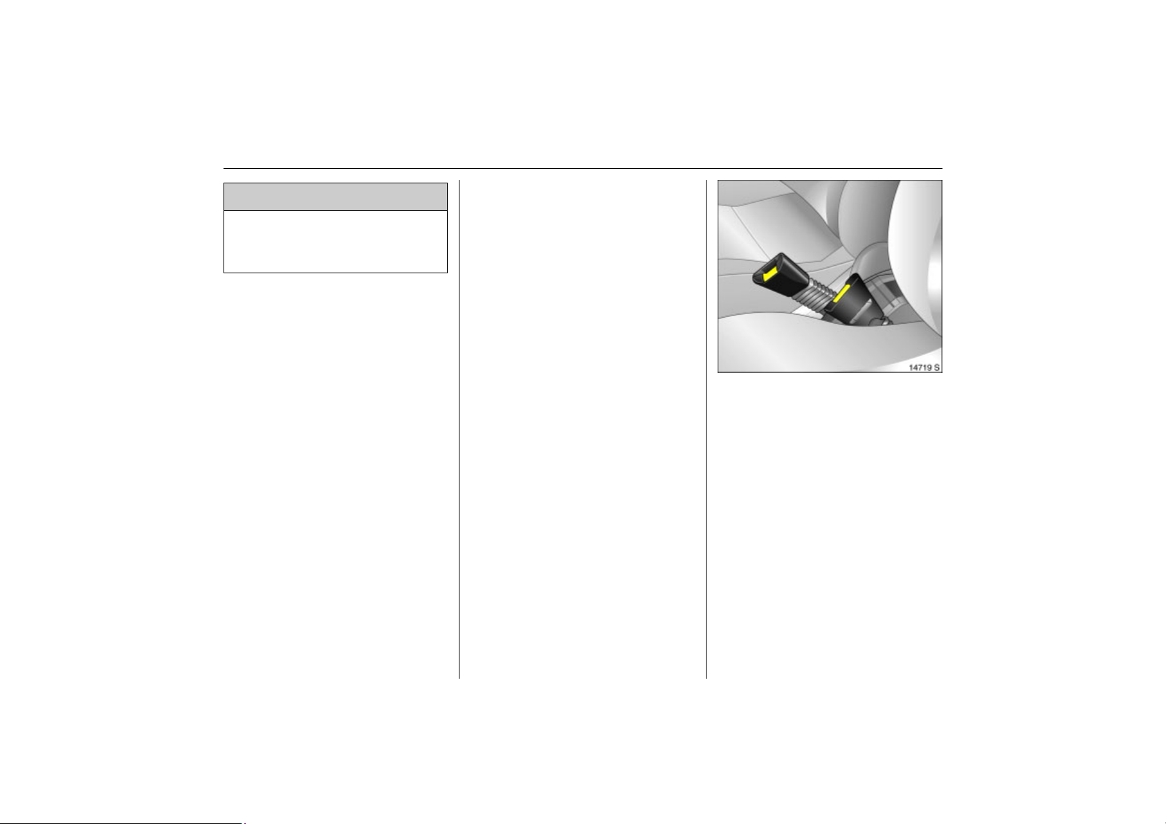
Picture no: 18531s.tif
Three-point seat belts
The seat belts have an automatic retractor,
so that the belt is spring tensioned and
always lies against the body.
Information on correct seat position 3 45.
The safety belts lock when the vehicle
accelerates or decelerates rapidly. This
prevents the belt from extending and
keeps the occupant in his or her seat.
Page 66
60 Seats, Interior
Back to overview
9 Warning
Fasten your seat belt before each trip.
In the event of an accident, persons not
wearing seat belts endanger their fellow
occupants and themselves.
Seat belt control indicator X 3 82.
Seat belts are only intended for one person.
They are not suitable for anyone under
12 years of age or under 150 cm tall.
For children under the age of 12, we
recommend the Opel child restraint system
3 65.
Belt force limiters
In the front seats, stress on the body is
reduced by dampened release of the
safety belt during a collision.
Checking the seat belts
From time to time, check operation of all
seat belt system components and check for
damage. Have damaged components
replaced. Have seat belts and deployed
belt tensioners replaced by an authorised
workshop after an accident.
Make sure that seat belts are not damaged
or trapped by sharp-edged objects.
Picture no: 14719s.tif
Belt tensioners
The front safety belt systems tighten at the
buckles in the event of a front or rear
collision above a specific degree of
severity. This tensions the seat belts.
Actuation of belt tensioners
is indicated by illumination of control
indicator v, see next column.
Triggered belt tensioners must be replaced
by a workshop. Belt tensioners can only be
triggered once.
Page 67
61Seats, Interior
Back to overview
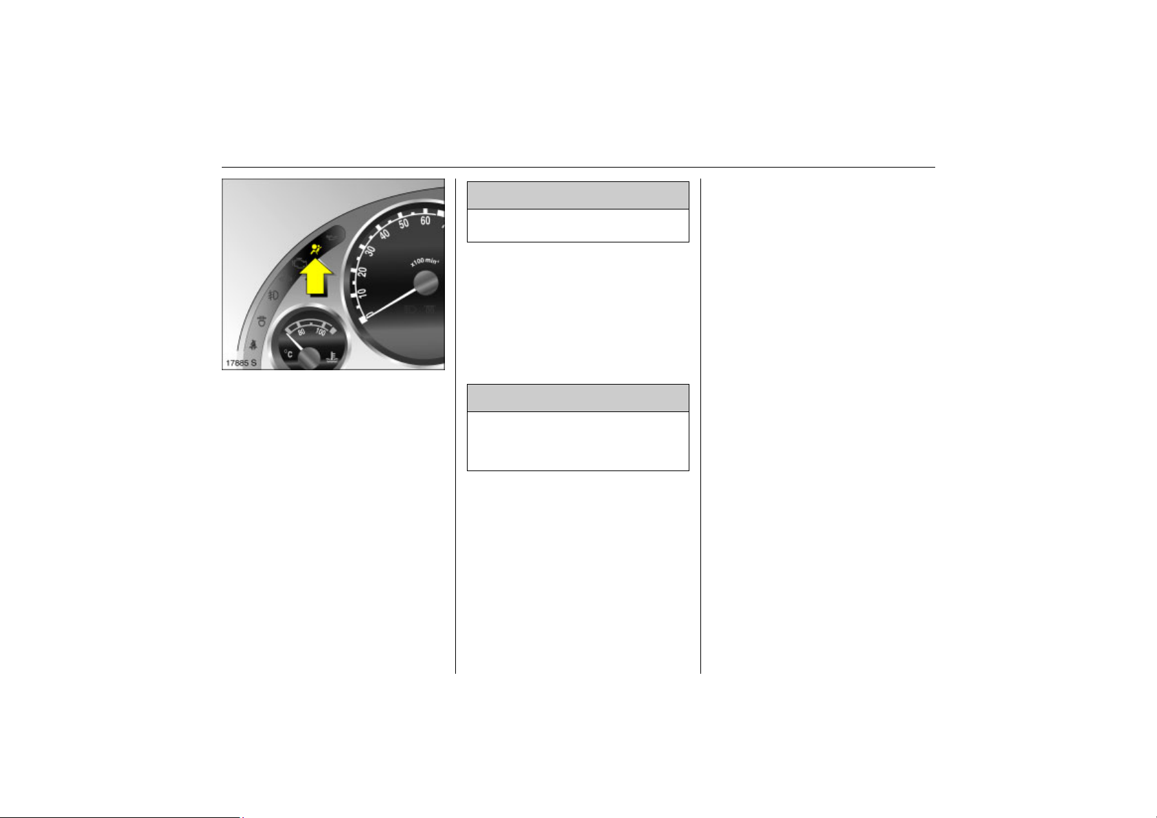
Control indicator v for belt tensioners
Picture no: 17885s.tif
The function of the belt tensioners and
airbag systems is monitored electronically
and indicated via control indicator v.
When the ignition is turned on, the control
indicator comes on for about 4 seconds.
If it does not light, does not go out after
4 seconds or comes on during driving,
there is a fault in the belt tensioner or
airbag systems 3 72.The systems may fail
to deploy in the event of an accident.
Deployment of the belt tensioners is
indicated by continuous illumination of v.
9 Warning
Have the cause of the fault remedied
immediately by a workshop.
The system’s integrated self-diagnostics
allows faults to be quickly remedied.
Important
z Do not affix or place accessories or other
objects within the deployment zone of
the belt tensioners. Do not make any
modifications to belt tensioner
components as this will invalidate the
vehicle type approval.
9 Warning
Incorrect handling (e.g. removal or
fitting of seat belts or belt buckles) can
cause the belt tensioners to deploy, with
risk of injury.
z The belt tensioner and airbag system
control electronics can be found in the
centre console area. In order to avoid
malfunctions, do not store magnetic
objects in this area.
z When the rear seats are being used it
must be ensured that the components of
the front seat belts are not damaged by
shoes or other objects. Do not allow dirt
to penetrate the seat belt inertia reels.
z We recommend that you have the seats
removed by a workshop.
z The belt tensioners only deploy once,
which can be detected by illumination of
the control indicator v. Have deployed
belt tensioners replaced by a workshop.
z The applicable safety regulations must
be adhered to when the vehicle is
disposed of. The vehicle should therefore
be disposed of by a recycling company.
Page 68
62 Seats, Interior
Back to overview
Loose or bulky clothing prevents the belt
from fitting snugly. Do not place objects
such as handbags or mobile phones
between the belt and your body.
9 Warning
The belt must not rest against hard or
fragile objects in the pockets of your
clothing.
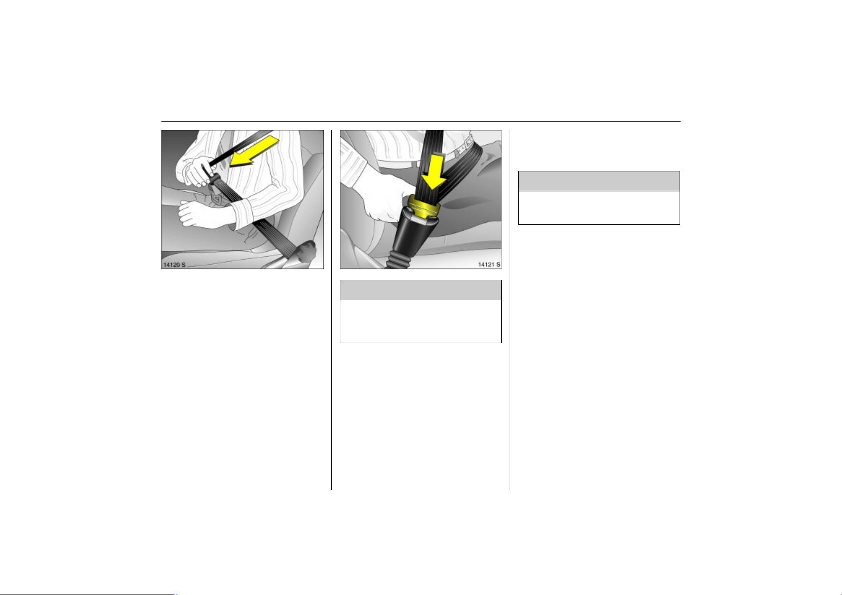
Picture no: 14120s.tif
Using the belts
Fitting seat belts
The seat belt must not be twisted and must
lie snugly against the body. The backrest
must not be tilted back too far (maximum
approx. 25).
Adjust the height so that the belt lies across
the shoulder. It must not lie across the
throat or upper arm.
Pull the belt out of the reel, guide it across
the body (making certain it is not twisted)
and engage the latch plate in the buckle.
Tension the lap belt frequently whilst
driving by tugging the shoulder belt.
Picture no: 14121s.tif
9 Warning
On pregnant women in particular, the
lap belt must be positioned as low as
possible across the pelvis so as not to
put too much pressure on the abdomen.
Page 69
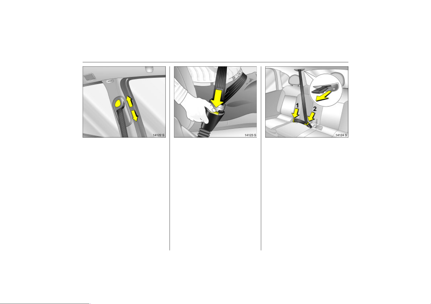
63Seats, Interior
Back to overview
Height adjustment
Picture no: 14122s.tif
Adjusting the height of the upper
deflection point of the front seat belts:
1. Unreel seat belt a little.
2. Push button on sliding adjuster.
3. Set desired height.
4. Allow sliding adjuster to audibly latch.
Do not adjust height while driving.
Removing the belt
Picture no: 14123s.tif
To release seat belt, press red button on
belt buckle.
Three-point seat belt on centre rear seat
Picture no: 14124S.tif
Pull latch plates out of belt retainer in roof.
Click bottom latch plate into right-hand
buckle (1) at middle seat. Remove top latch
plate from retainer, guide over shoulder
and lap area with belt (do not twist) and
click into left buckle (2) at middle seat.
If using the centre seat, both outboard
seats must be pushed backward and the
backrests must be flush with the centre
seat backrest 3 52.
Page 70
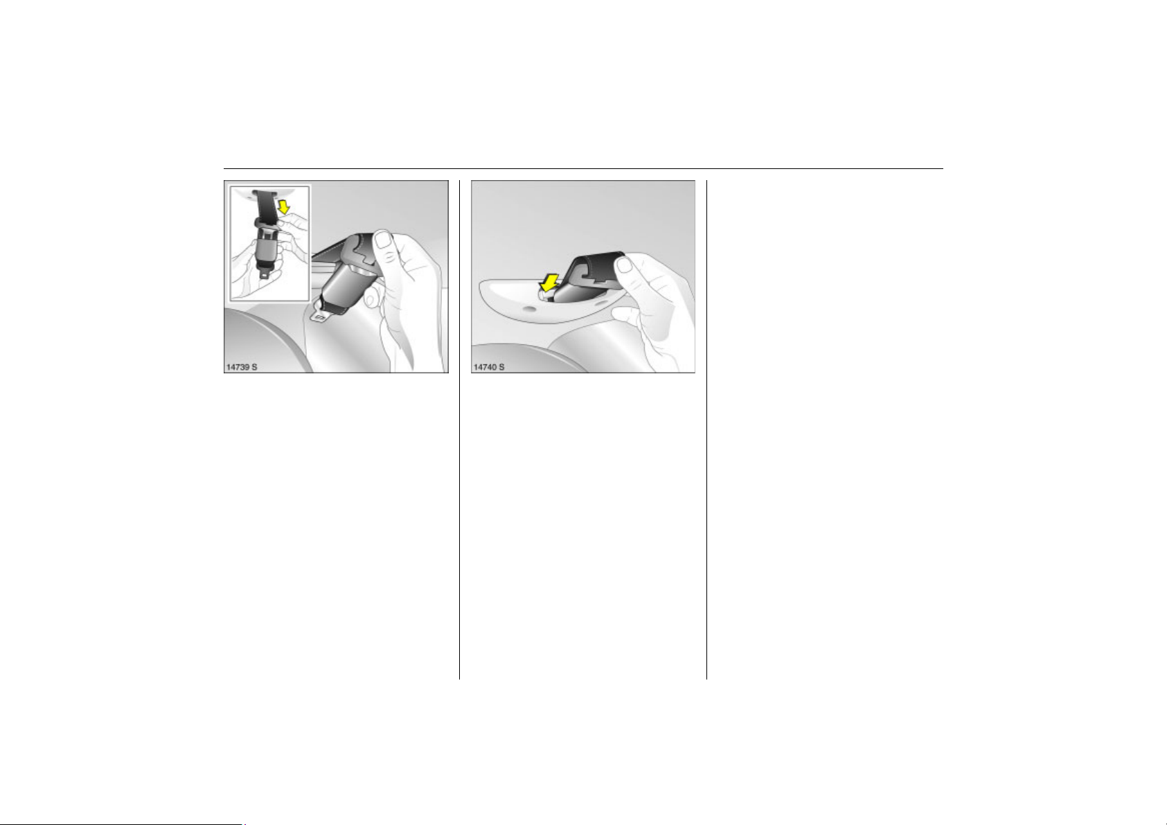
64 Seats, Interior
Back to overview
Mounting clips 3 for ISOFIX child
restraint systems
The ISOFIX points for fitting a child seat are
located between the seat backrest and the
seat surface.
Fasten permitted ISOFIX child restraint
systems to the mounting brackets.
Closely follow the installation instructions
accompanying the ISOFIX child restraint
system.
To remove the seat belt, press the button
Picture no: 14739S.tif
on the left buckle (2). If the centre seat is
lowered, press the button on the right
buckle (1). The seat belt retracts
automatically.
Push the upper latch plate into the holder
for the lower latch plate. Fold over locked
together latch plates against the seat belt.
Insert in the seat belt holder in the roof with
Picture no: 14740S.tif
the lower latch plate pointing forward.
Page 71
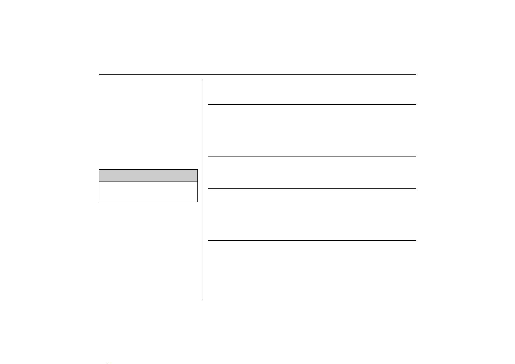
65Seats, Interior
Back to overview
Child restraint system 3
Follow the usage instructions for the child
restraint system.
Always comply with local or national
regulations. In some countries, the use of
child restraint systems is forbidden on
certain seats.
Selecting the right system
Your child should be transported facing the
rear in the vehicle for as long as possible.
The very weak cervical vertebrae of a child
will be under less stress in an accident if
your child is facing the rear and semihorizontal, than when he is sitting upright.
9 Warning
Child restraint systems must not be
carried on a passenger’s lap. Danger
to life.
Permissible options for fitting a child safety seat
Weight and
age class
2)
On front
passenger seat
On outboard seats in
the rear seats
Group 0:
up to 10 kg
or approx.
10 months
1
, + U, + U, ++
B
Group 0+:
up to 13 kg
or approx.
2years
Group I:
9to18 kg
or approx.
2
, + U, + U, ++
B
8months
to 4 years
Group II:
15 to 25 kg
or approx.
3 to 7 years
X U U, ++
Group III:
22 to 36 kg
or approx.
6 to 12 years
1)
On centre
rear seat
1)
For reasons of safety, we recommend that the child safety seat be installed on one of the outer
rear seats.
2)
We recommend the use of each system until the child reaches the upper weight limit.
Page 72

66 Seats, Interior
Back to overview
1
= Conditional, without front
B
passenger airbags or with seat
occupancy recognition and Opel
child restraint systems with
transponders.
The front passenger seat must also
have a height adjusting facility:
move to highest position, slide front
passenger seat all the way back and
move front passenger seat belt
anchorage point to lowest possible
position.
2
= Conditional, without side airbag, of
B
front passenger seat has been slid
all the way back, or with seat
occupancy recognition and Opel
child restraint systems with
transponders.
The front passenger seat must also
have a height adjusting facility:
move to highest position and slide
front passenger seat all the way
back so that the seat belt runs
towards the front from the
anchorage point.
U = Universal suitability in conjunction
with three-point seat belt.
+ = Vehicle seat available with ISOFIX
fixings. When using ISOFIX, only
ISOFIX child restraint systems
approved for the vehicle may be
used.
++ = Only if both outboard seats are
pushed back and flush with the
centre seat.
X = No child restraint system permitted
in this weight class.
Note
z Children under 12 years or under 150 cm
tall should only travel in an appropriate
child restraint system.
z When transporting children, use the child
restraint systems suitable for the child’s
weight.
z Ensure correct installation of child
restraint system, see the instructions
enclosed with the system.
z The covers of the Opel child restraint
system can be wiped clean.
z Do not stick anything on the child
restraint systems and do not cover them
with any other materials.
z Only allow children to enter and exit at
the side facing away from the traffic.
z A child restraint system which has been
subjected to stress in an accident must
be replaced.
z Secure or remove child restraint systems
that are in the vehicle but not in use.
Page 73
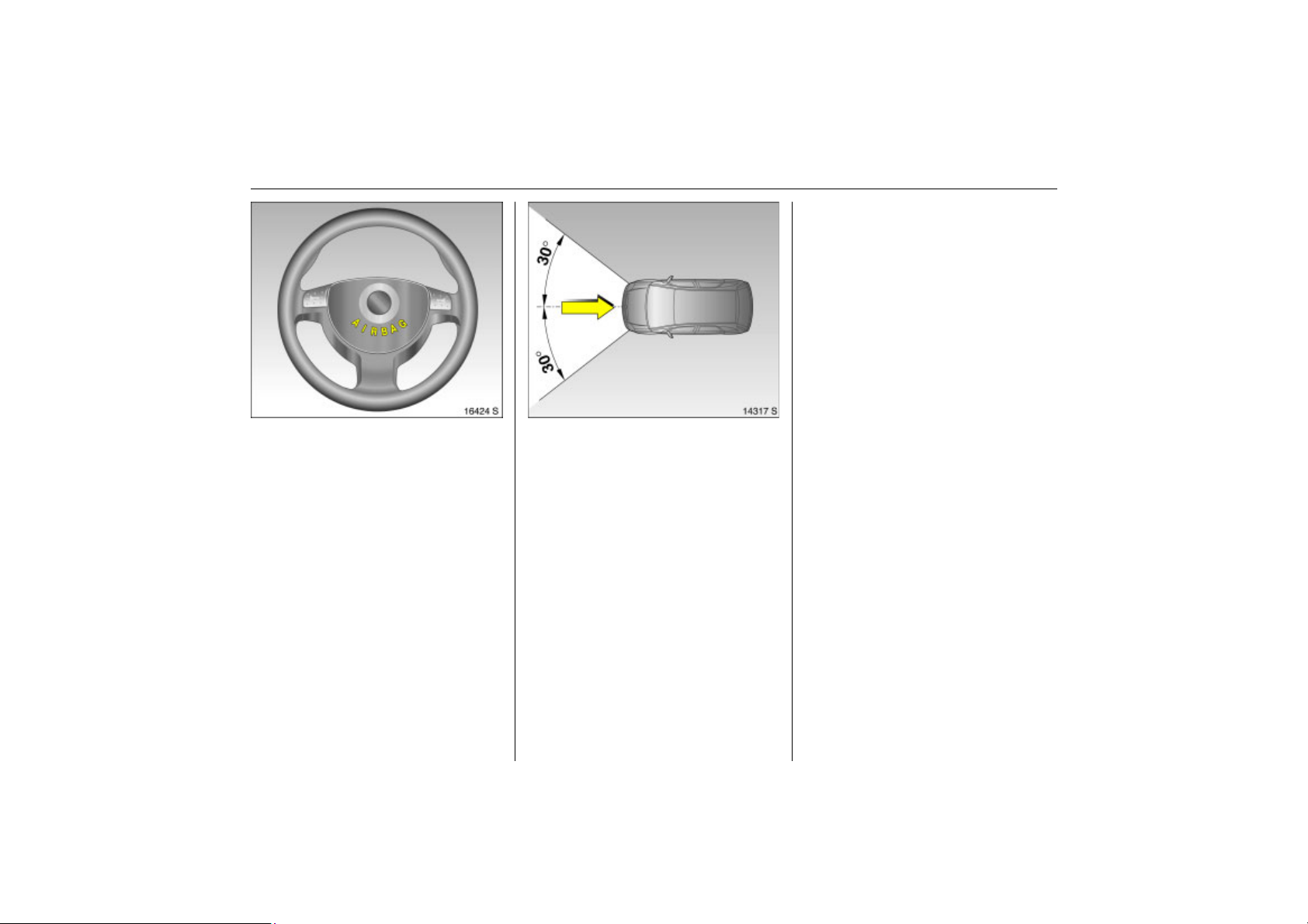
Picture no: 16424s.tif
Back to overview
Airbag system
Front airbag
The front airbag system consists of one
airbag in the steering wheel and one in the
instrument panel. These can be identified
by the word AIRBAG.
The front airbag system comprises:
z an airbag with inflator in the steering
wheel and a second one in the
instrument panel 3,
z the control electronics with impact
sensor,
z the control indicator for airbag
systems v in the instrument,
z seat occupancy recognition 3,
Picture no: 14317s.tif
z the control indicator for Opel child
restraint systems
in the courtesy lamp.
The front airbag system will be triggered:
z depending on the severity of the
accident,
z depending on the type of impact,
z within the range shown in the illustration,
z independently of the side airbag
system 3 and curtain airbag system 3.
The ignition must be switched on.
y with transponders 3
67Seats, Interior
Exception:
Passenger seat with a seat occupancy
recognition system 3. The occupancy
recognition system deactivates the front
and side airbags for the passenger when
the seat is unoccupied or an Opel child
restraint system with transponders 3 is
fitted to the passenger seat. Seat
occupancy recognition 3 72. Opel child
restraint system with transponders 3 3 73.
Examples of events triggering the front
airbag system:
z Impact against a non-yielding obstacle:
the front airbags are triggered at low
vehicle speed.
z Impact against a yielding obstacle (such
as another vehicle): the front airbags are
only triggered at a higher vehicle speed.
Page 74
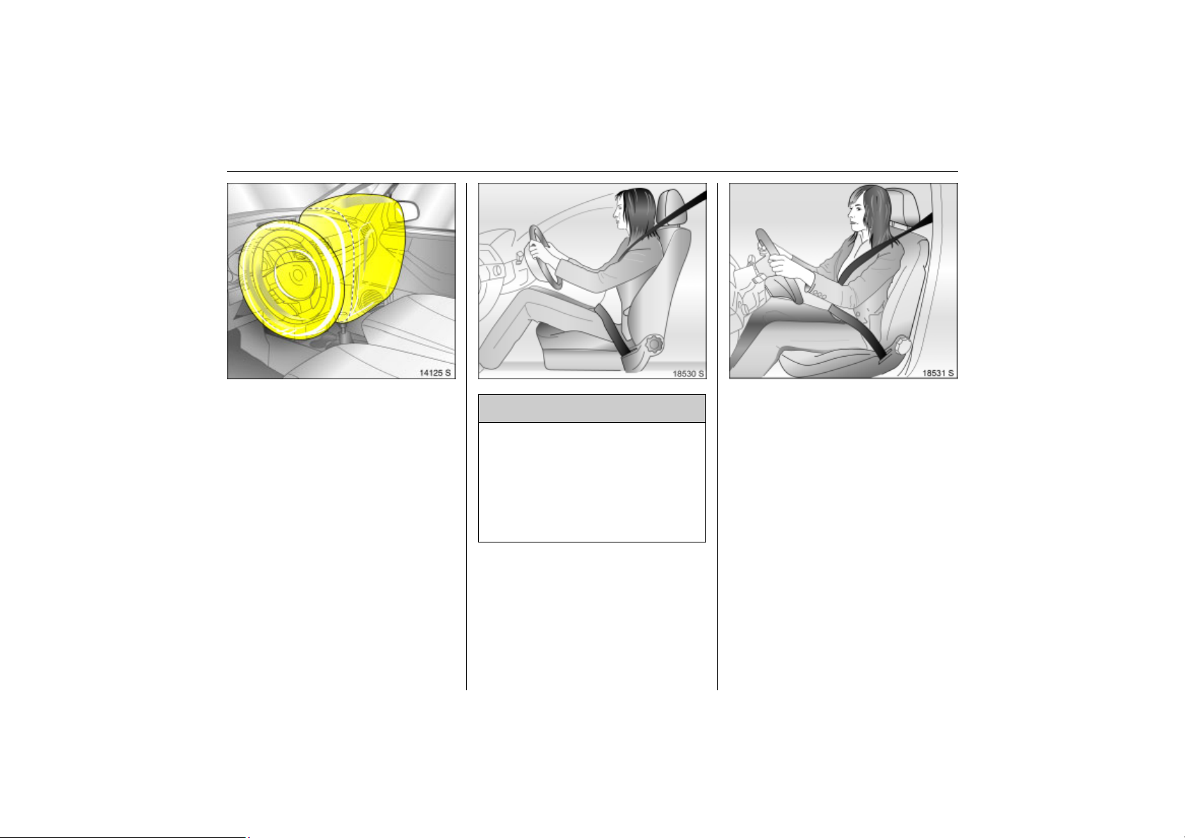
68 Seats, Interior
Back to overview
When triggered, the front airbags inflate in
Picture no: 14125s.tif
milliseconds to form a safety cushion for
the driver and front passenger. The
forward movement of the front seat
occupants is checked, thereby
substantially reducing the risk of injury to
the upper body and head.
No impairment of view will occur, because
the airbags inflate and deflate so quickly
that it is often not even noticed in an
accident.
Picture no: 18530s.tif Picture no: 18531s.tif
9 Warning
Optimum protection is only provided
with the seat in the proper position 3 45.
Keep the area in which the airbag
inflates clear of obstructions.
Wear the three-point seat belt properly
fastened. The front airbag system is an
additional safety device, not a
replacement for your seat belt.
The front airbag system will not be
triggered in the event of
z the ignition is switched off,
z minor frontal collisions,
z accidents in which the vehicle overturns,
z collisions involving a side or rear impact,
that is to say, if it would not be of benefit to
the occupants.
Page 75
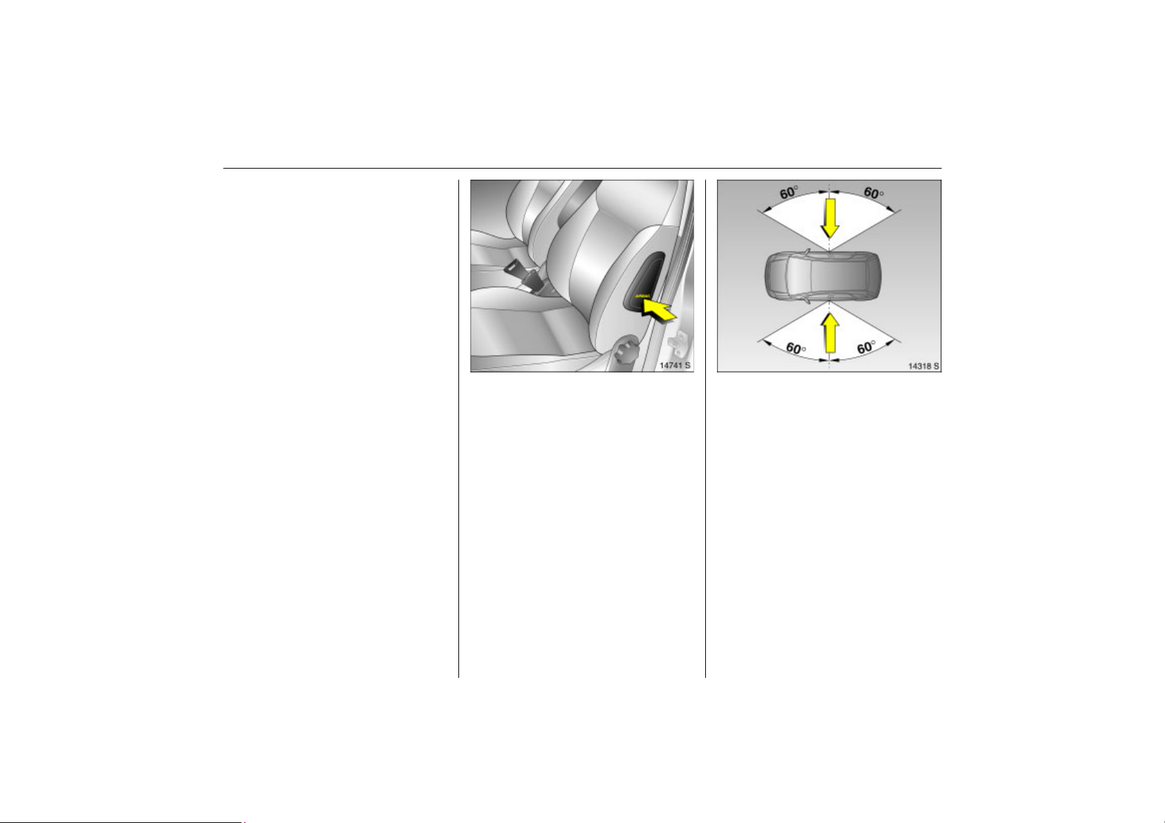
In addition, the front airbag system will not
Back to overview
be triggered for the front passenger in
versions with seat occupancy recognition 3
if
z the front passenger seat is unoccupied,
z or there is a properly mounted Opel child
restraint system with transponders 3.
Seat occupancy recognition 3 72. Opel
child restraint system with
transponders 3 3 73.
69Seats, Interior
Side airbag 3
Picture no: 14741s.tif
The side airbag system consists of an
airbag in each front seat backrest. This can
be identified by the word AIRBAG.
The side airbag system comprises:
z an airbag with inflator in the back of the
driver’s and front passenger seat
respectively
z the control electronics,
z the side impact sensors,
z the control indicator for airbag
systems v in the instrument,
z seat occupancy recognition 3,
z the control indicator for Opel child
restraint systems
in the courtesy lamp.
y with transponders 3
The side airbag system will be triggered:
Picture no: 14318s.tif
z depending on the severity of the
accident,
z depending on the type of impact,
z within the range shown in the illustration
on the centre door pillar of the driver’s or
front passenger side,
z independently of the front airbag
system.
The ignition must be switched on.
Page 76
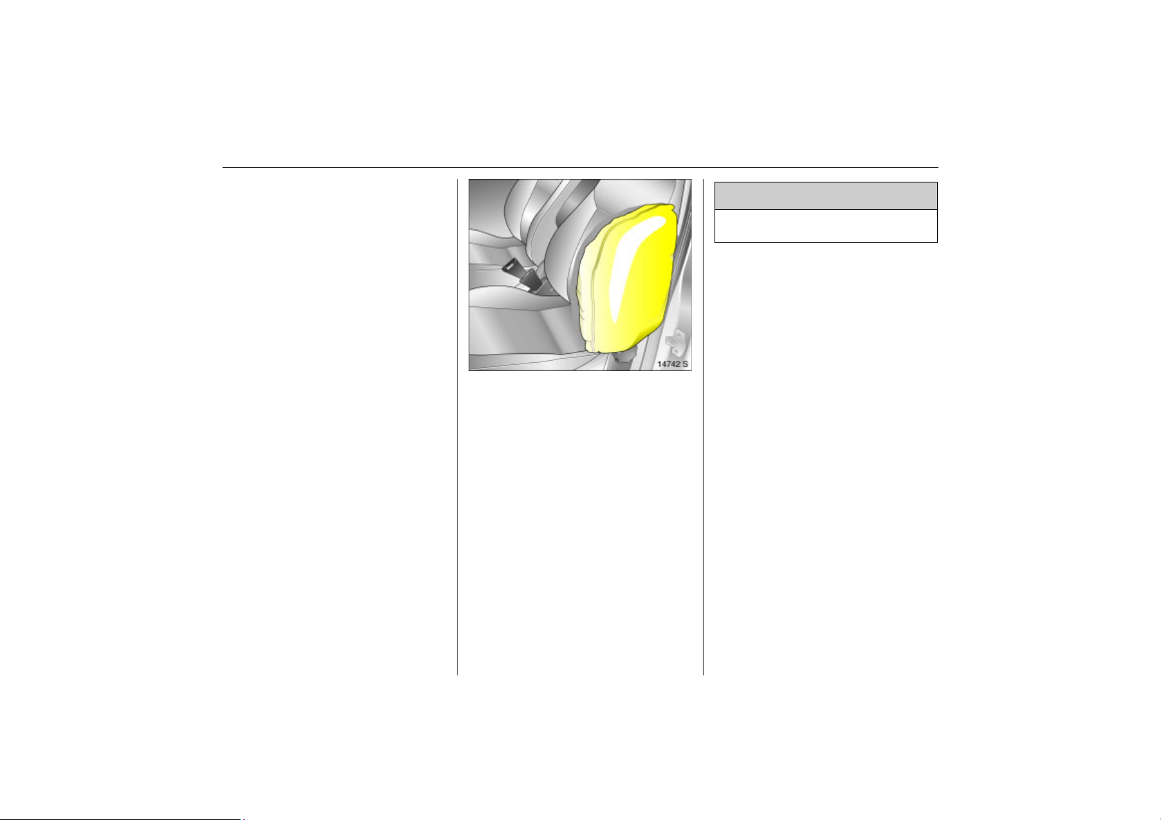
70 Seats, Interior
Back to overview
Exception:
Passenger seat with a seat occupancy
recognition system 3. The occupancy
recognition system deactivates the front
and side airbags for the passenger when
the seat is unoccupied or an Opel child
restraint system with transponders 3 is
fitted to the passenger seat. Seat
occupancy recognition 3 72. Opel child
restraint system with transponders 3 3 73.
When deployed, the side airbag inflates
Picture no: 14742s.tif
within milliseconds to form a safety cushion
for the driver or front passenger in the
respective front door area. This
substantially reduces the risk of injury to
the upper body and pelvis in the event of a
side-on collision.
9 Warning
Keep the area in which the airbag
inflates clear of obstructions.
The side airbags will not be triggered in the
event of
z the ignition is switched off,
z frontal collisions,
z accidents in which the vehicle overturns,
z collisions involving a rear impact,
z collisions involving a side impact outside
the passenger cell.
In addition, the side airbag system will not
be triggered for the front passenger in
versions with seat occupancy recognition 3
if
z the front passenger seat is unoccupied
z or there is a properly mounted Opel child
restraint system with transponders 3.
Seat occupancy recognition 3 72. Opel
child restraint system with
transponders 3 3 73.
Page 77
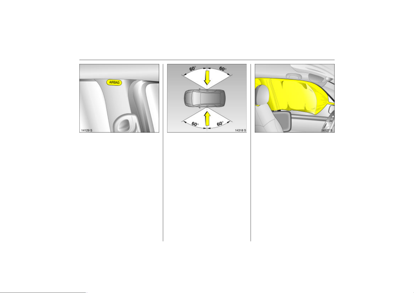
71Seats, Interior
Back to overview
Curtain airbag 3
Picture no: 14129s.tif
The curtain airbag system consists of an
airbag in the roof frame on each side. This
can be identified by the word AIRBAG on
the roof pillar.
The curtain airbag system comprises:
z an airbag with inflator in the roof frame
on the driver’s and front passenger side
respectively,
z the control electronics,
z the side impact sensors,
z the control indicator for airbag
systems v in the instrument.
The curtain airbag system will be triggered:
Picture no: 14318s.tif
z depending on the severity of the
accident,
z depending on the type of impact,
z within the range shown in the illustration
on the centre door pillar of the driver’s or
front passenger side,
z together with the side airbag system,
z irrespective of seat occupancy
recognition,
z independently of the front airbag
system.
The ignition must be switched on.
When the curtain airbag is triggered it
Picture no: 14127s.tif
inflates within milliseconds and provides a
safety barrier in the head area on the
respective side of the vehicle. This reduces
the risk of injury to the head considerably in
case of a side impact.
Page 78
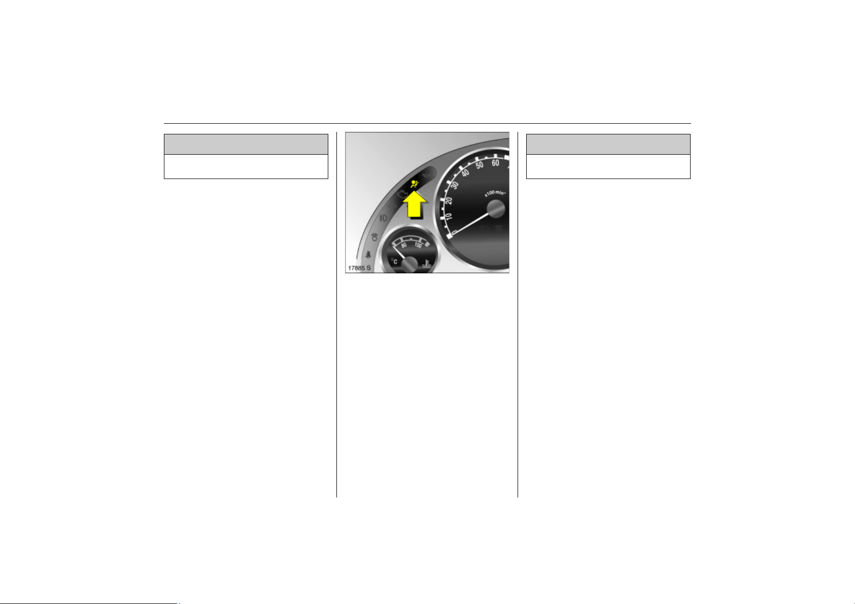
72 Seats, Interior
Back to overview
9 Warning
Keep the area in which the airbag
inflates clear of obstructions.
The curtain airbags will not be triggered in
the event of
z the ignition is switched off,
z frontal collisions,
z accidents in which the vehicle overturns,
z collisions involving a rear impact,
z collisions involving a side impact outside
the passenger cell.
Control indicator v for airbag systems
Picture no: 17885s.tif
The function of the airbag systems and
seat occupancy recognition 3 is monitored
electronically and indicated via control
indicator v. When the ignition is turned on,
the control indicator comes on for
about 4 seconds. If it does not light, does
not go out after 4 seconds or comes on
during driving, there is a fault in the airbag
systems, the seat occupancy recognition
system 3 or the belt tensioners 3 61. The
systems may fail to deploy in the event of
an accident.
Deployed airbags are indicated by
continuous illumination of v.
9 Warning
Have the cause of the fault remedied
immediately by a workshop.
The system’s integrated self-diagnostics
allows faults to be quickly remedied.
Seat occupancy recognition 3
The seat occupancy recognition system
deactivates the front and side front
passenger airbags if the front passenger
seat is unoccupied or an Opel child
restraint system with transponders 3 has
been fitted to the front passenger seat. The
curtain airbag system 3 remains activated.
The control indicator for seat occupancy
recognition
lamp. If this control indicator
for approx. 4 seconds after the ignition is
switched on, the vehicle is equipped with
seat occupancy recognition 3 73,
Fig. 12097 S.
If an Opel child restraint system with
transponders 3 is fitted, this control
indicator
ignition is switched on as soon as the
system has detected the child restraint
system. Only then may the child restraint
system with transponders 3 be used on the
passenger seat.
y is located in the courtesy
y illuminates
y lights permanently after the
Page 79
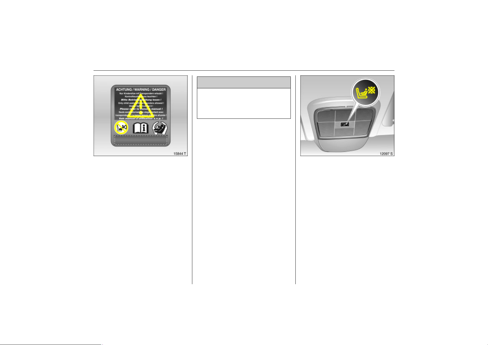
Vehicles with seat occupancy recognition
Back to overview
Picture no: 15844t.tif
can be identified by the sticker on the front
passenger seat or on the side of the
instrument panel.
Opel child restraint systems with
transponders 3 are detected
automatically when installed properly on
the passenger seat. When these child
restraint systems are used on the
passenger seat, the front and side airbag
systems for the passenger seat are
deactivated. The curtain airbag system
remains activated. Observe the control
indicator
recognition 3 3 73.
y for seat occupancy
9 Warning
Only Opel child restraint systems with
transponders 3 should be fitted on the
front passenger seats. Use of systems
without transponders poses a risk of
fatal injury.
Opel child restraint systems with
transponders 3 can be identified by a
sticker or badge.
Control indicator
restraint systems with transponders 3
The presence of an Opel child restraint
system with transponders 3 is indicated
after the ignition has been switched on by
permanent illumination of the control
indicator
as the seat occupancy recognition system
has detected the child restraint system.
y in the courtesy lamp, as soon
y for Opel child
73Seats, Interior
Picture no: 12097s.tif
If the control indicator does not come on
while driving, the front and side airbags for
the passenger are not de-activated and
there is a risk of injury or death to the child.
Fit child restraint systems on the rear seat.
Have the cause of the fault eliminated by a
workshop.
If the child restraint system is not correctly
installed or the transponders are defective,
the indicator lamp will flash. Check for
correct child restraint system installation.
For installation of child restraint system
with transponders 3 – see instructions
provided with child restraint system.
Page 80
74 Seats, Interior
Back to overview
If the control indicator flashes when the
child restraint system with transponders 3
is correctly fitted, there is a fault with risk of
injury to the child. Fit child restraint systems
on the rear seat. Have the cause of the
fault eliminated by a workshop.
If no Opel child restraint system with
transponders 3 is fitted, the control
indicator must not light or flash as the
passenger airbag systems would not
deploy. Have the cause of the fault
eliminated by a workshop.
9 Warning
If the Opel child restraint system with
transponders 3 has been fitted
according to the instructions, the control
indicator for Opel restraint systems with
transponders must illuminate in the
courtesy lamp when the ignition is
switched on.
If the control indicator does not come on
while driving, the passenger airbag
systems are not de-activated and there
is a risk of injury or death. In this case fit
child restraint systems on the rear seat.
Have the cause of the fault eliminated
by a workshop.
Important
z Placing accessories and objects in the
expansion region of the airbag systems
is not permitted due to the risk of injury if
the airbag is triggered.
z Do not place any objects between the
airbag systems and the vehicle
occupants; danger of injury.
9 Warning
As with any other object, child restraint
systems must not be carried on a
passenger’s lap. Danger to life.
z Use the hooks in the roof frame only to
hang up light articles of clothing or coat
hangers. Do not place any objects in the
pockets of the hanging items – risk of
injury.
z The airbag systems and belt tensioner
control electronics can be found in the
centre console area. In order to avoid
malfunctions, do not store magnetic
objects in this area.
z Do not stick anything on the steering
wheel, instrument panel, front seat
backrests or roof frame in the vicinity of
the airbags, or on the front passenger’s
seat cushion, or cover any of those areas
with other materials.
z Use only a dry cloth or interior cleaner to
clean the steering wheel, instrument
panel, front seat backrests, roof frame
and seat cushion of the front passenger
seat. Do not use any aggressive cleaning
agents.
z Only protective covers which are
approved for your vehicle with side
airbag may be fitted on the front seats.
When fitting the protective covers, make
sure that the airbag units on the
outboard sides of the front seat
backrests are not covered.
z The airbag systems are triggered
independently of each other depending
on the severity of the accident and the
type of impact. The side airbag system 3
and the curtain airbag system 3 are
triggered together.
z Each airbag deploys once only. Have a
workshop replace deployed airbags
immediately.
Page 81
75Seats, Interior
Back to overview
z The speeds, directions of movement and
deformation properties of the vehicles,
and the properties of the obstacle
concerned, determine the severity of the
accident and triggering of the airbags.
The degree of damage to your vehicle
and the resulting repair costs alone are
not indicative that the criteria for
triggering of the airbags were met.
z Do not perform any alterations on the
components of the airbag system, as this
would render the vehicle unroadworthy.
9 Warning
If handled improperly the airbag
systems can be triggered in an explosive
manner – risk of injury!
z We recommend having the steering
wheel, the instrument panel, all panelling
parts, the door seals, the handles and
the seats removed by a workshop.
z The applicable safety regulations must
be adhered to when the vehicle is
disposed of. The vehicle should therefore
be disposed of by a recycling company.
z Persons weighing less than 35 kg should
only travel on the rear seats. This does
not apply to children who are travelling
in child restraint systems with
transponders 3.
z In vehicles with seat occupancy
recognition 3, do not place any heavy
objects on the front passenger seat
otherwise the airbag systems for the
front passenger seat may be triggered in
the event of an accident.
z In vehicles with seat occupancy
recognition 3, to prevent malfunctions
do not use protective covers or seat
cushions on the front passenger seat.
z When using an Opel child restraint
system with transponders 3 on the front
passenger seat, in order to prevent
malfunctions, no objects (e.g. plastic
sheet, stickers or heated mats) may be
placed under the child restraint system.
9 Warning
Child restraint systems or other objects
must never be carried on the laps of
passengers; If carried in this way, child
restraint systems with transponders 3 in
vehicles with seat occupancy
recognition 3 could lead to front
passenger airbag systems not being
triggered in the event of an accident.
Page 82

76 Seats, Interior
Back to overview
Use of child restraint systems 3 on the
front passenger seat in vehicles with
airbag systems 3, but without seat
occupancy recognition 3
9 Warning
Vehicles with front passenger airbag 3
without side airbag 3: Child seats facing
the rear of the vehicle must not be
installed on the front passenger seat,
risk of fatal injury. Child seats facing the
direction of travel (child seats for weight
classes I, II and III, following pages) may
be installed on the front passenger seat
if the seat has been pushed back as far
as it will go and the backrest has been
adjusted such that the lap belt fits
snugly.
Vehicles with front passenger airbag can
Picture no: 11704a.tif
be recognised by the word AIRBAG above
the glove compartment and by the sticker
on the instrument panel on the passenger
side - see Fig. 11704 A.
Picture no: 14791s.tif
9 Warning
Vehicles with side airbag 3: No child
restraint system 3 may be fitted on the
front passenger’s seat; risk of fatal
injury.
A vehicle with side airbags can be
identified by the word AIRBAG on the
outboard sides of the front seat backrests.
Seat occupancy recognition 3 3 72.
Page 83
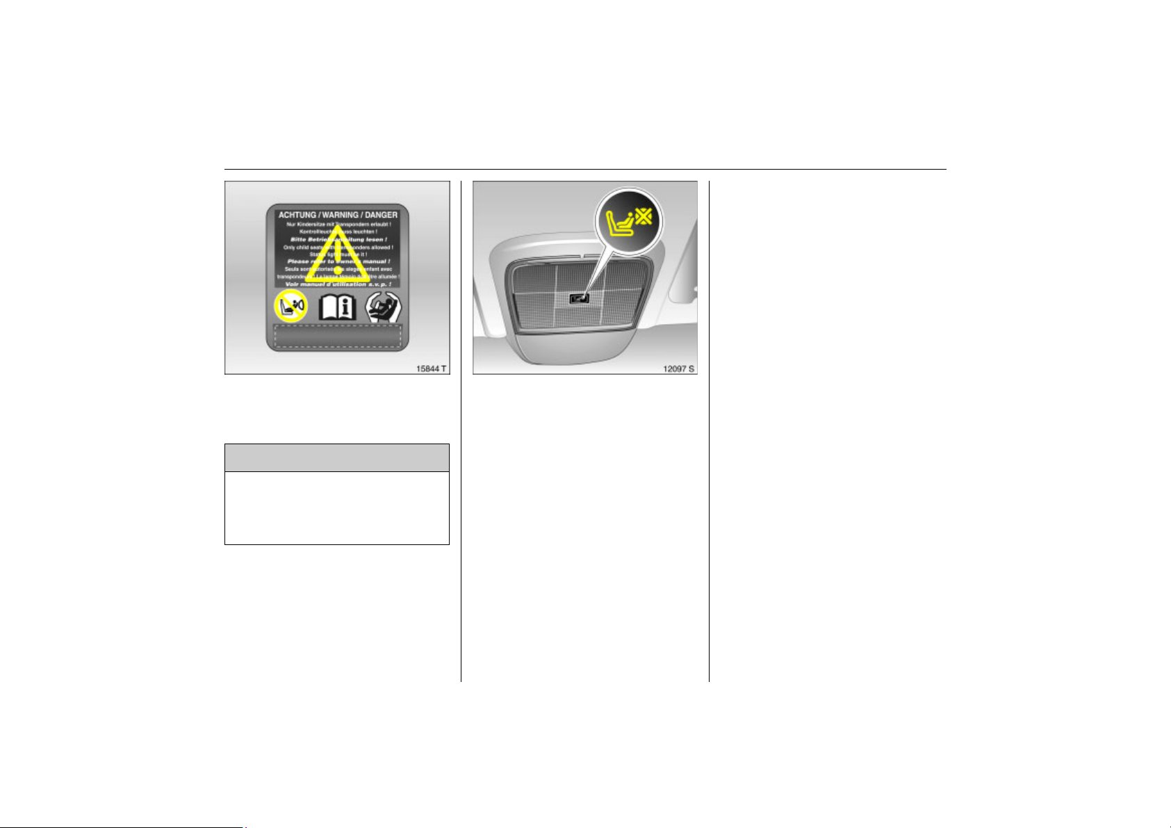
77Seats, Interior
Back to overview
The seat occupancy recognition system
detects Opel child restraint systems with
transponders 3 and switches off the front
and side airbag systems for the front
passenger seat. The curtain airbag system
remains activated. Seat occupancy
recognition 3 72.
Opel child restraint systems with
transponders 3 can be identified by a
sticker or badge.
Use of child restraint systems 3 on front
Picture no: 15844t.tif
passenger seat in vehicles with airbag
systems 3 and with seat occupancy
recognition 3
9 Warning
Only Opel child restraint systems with
transponders 3 can be fitted on the
front passenger seats. Use of systems
without transponders poses a risk of
fatal injury.
Vehicles with seat occupancy recognition
are identified by a sticker on the lower
panel of the front passenger seat –
see Fig. above.
Vehicles with seat occupancy recognition
Picture no: 12097s.tif
can also be recognised by control
indicator
illuminates for approx. 4 seconds after the
ignition is switched on, the vehicle is
equipped with seat occupancy recognition
3 72.
y. If control indicator y
Page 84
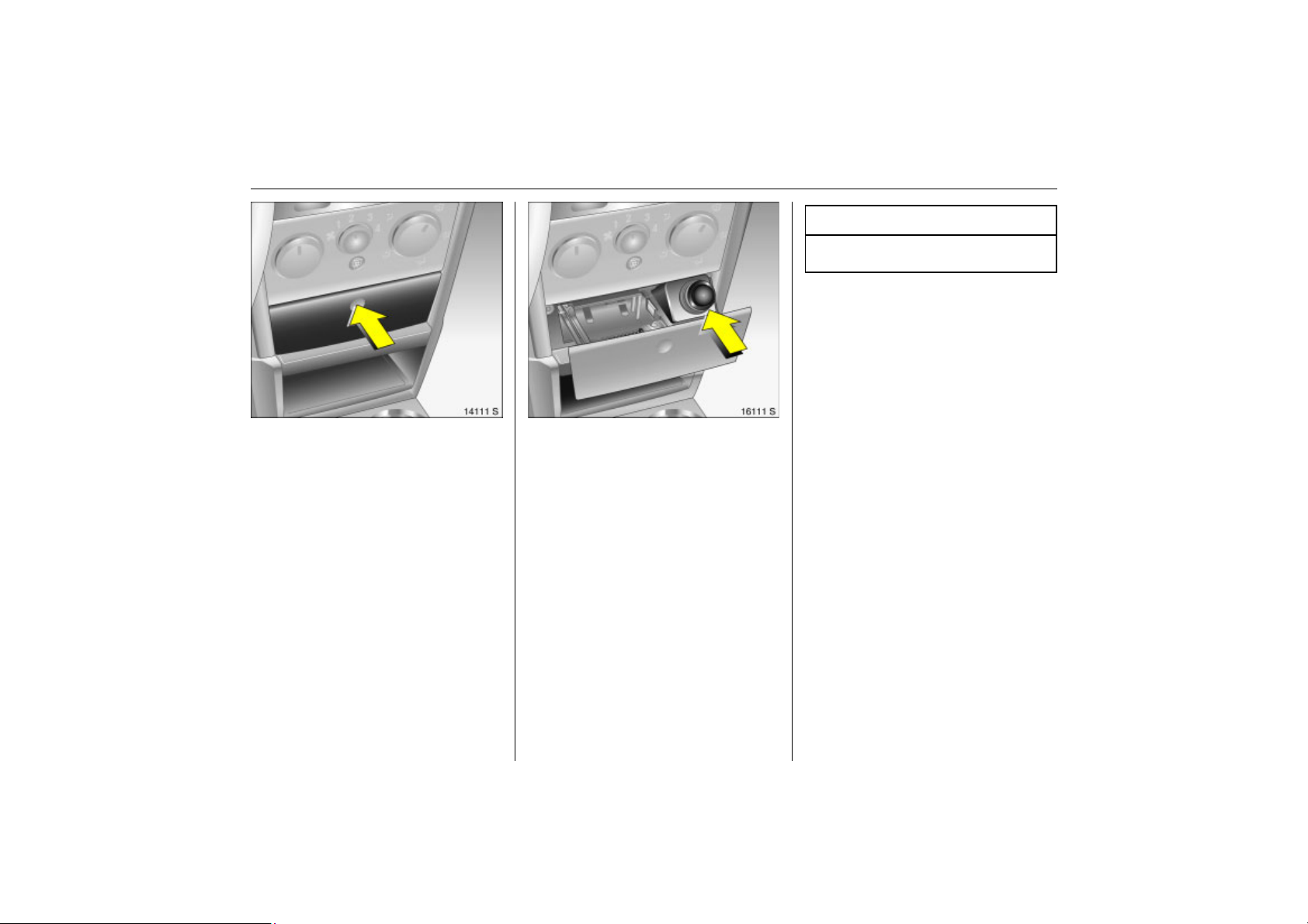
78 Seats, Interior
Back to overview
Picture no: 14111s.tif
Cigarette lighter 3
The cigarette lighter is behind the ashtray
cover in the centre console.
The ashtray cover opens when pressed at
the point indicated.
Press cigarette lighter with ignition
switched on. Switches off automatically
when element is hot. Withdraw cigarette
lighter.
Picture no: 16111s.tif
Accessory sockets 3
The accessory socket is behind the cover in
the centre console. Further accessory
sockets 3 are located in the centre console
in front of the rear seats and in the luggage
compartment.
Accessory sockets are operable when the
ignition is switched on. Use of the sockets
while the engine is not running will drain
the battery.
Caution
Do not damage the socket by using
unsuitable plugs.
Do not exceed the maximum power
consumption of 120 watts.
Electrical accessories connected to the
socket must comply with the
electromagnetic compatibility
requirements laid down in DIN VDE 40 839,
otherwise vehicle malfunctions may occur.
Do not connect any current-delivering
accessories, e.g. electrical charging
devices or batteries.
If the tyre repair set is 3 is in operation, no
consumers may be connected to the
auxiliary socket.
Page 85
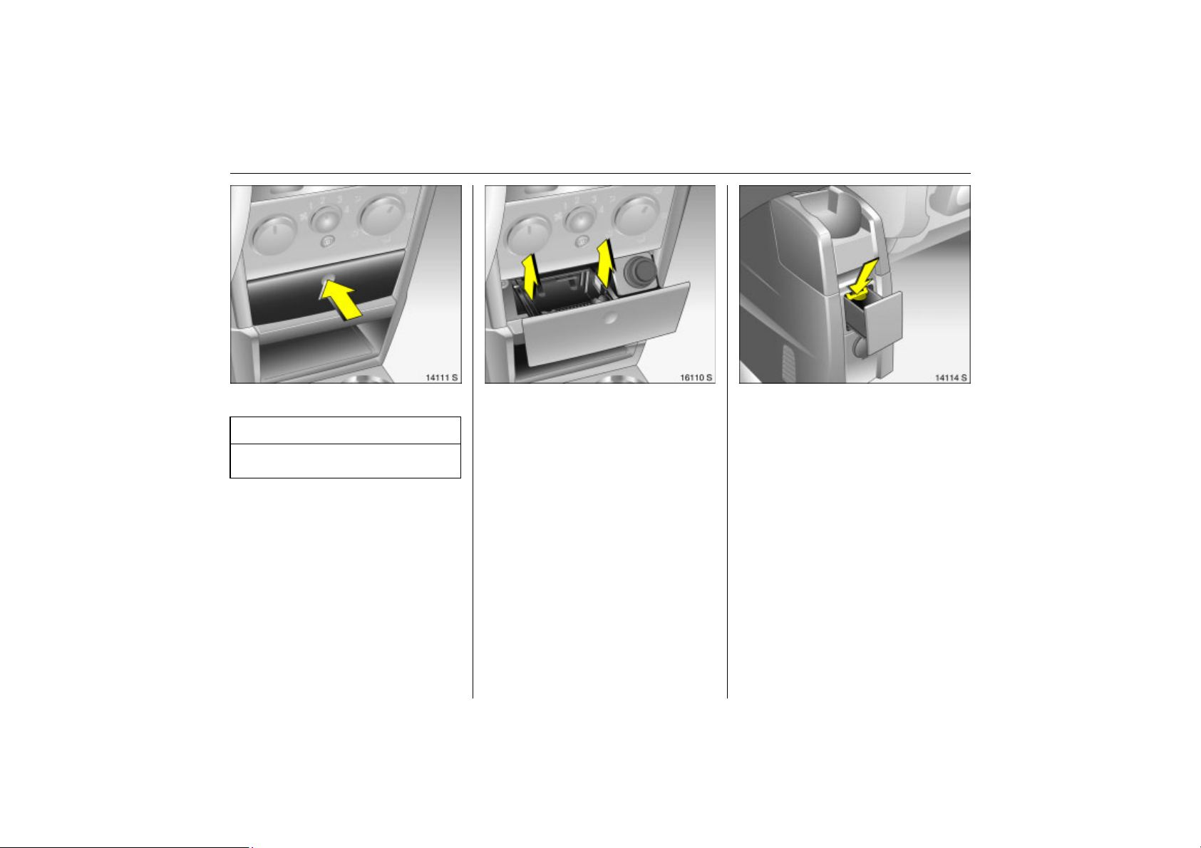
79Seats, Interior
Back to overview
Picture no: 14111s.tif
Ashtrays
Caution
To be used only for ash and not for
combustible rubbish.
Ashtray, front
The ashtray is behind a cover in the centre
console.
The cover opens when pressed at the point
indicated.
To empty, grip both sides of the ashtray
Picture no: 16110s.tif
insert at the spots illustrated and pull
upwards.
Rear ashtray 3
Picture no: 14114s.tif
The ashtray is in the rear centre console.
To open, pull ashtray towards the back of
the vehicle.
To empty: open the ashtray, press the
spring (arrow) and pull out the ashtray.
Page 86
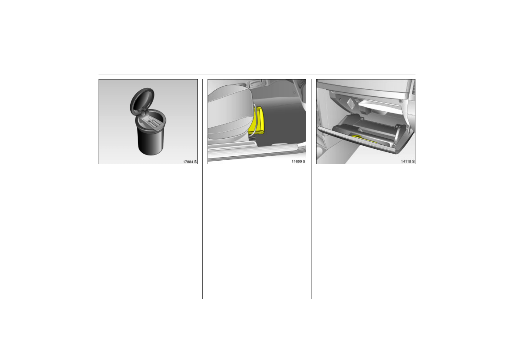
80 Seats, Interior
Back to overview
Ashtray 3
Picture no: 17884s.tif
The ashtray can be put in the front or rear
of the centre console or in the oddments
tray 3.
To use, open cover.
Picture no: 11699s.tif
Stowage compartments
Stowage compartment 3 beneath
passenger seat
Lift stowage compartment by grasping
recessed edge and pull out. Maximum
load: 1 kg. To close the stowage
compartment, push it in and engage.
Glove compartment
Picture no: 14115s.tif
To open, pull handle upwards.
On the inside of the glove compartment
cover there is a pen holder.
The glove compartment should remain
closed while driving.
Page 87
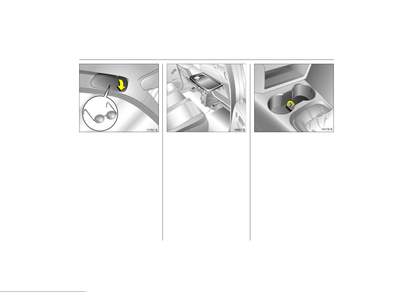
81Seats, Interior
Back to overview
Stowage compartment for glasses 3
Picture no: 11701s.tif
On driver’s side: fold down to open.
Do not store heavy objects in the stowage
compartment.
Picture no: 18601s.tif
Foldaway tables 3
These are located in the front seat
backrests.
Open by pulling upward until it engages.
Fold away by pressing down past the
resistance point.
Do not place any heavy objects on the
table.
Picture no: 14116s.tif
Coin holder 3
In the centre console.
Sun visors
Use the sun visor to protect from glare by
pulling it down and swivelling it to the side.
The mirror covers in the sun visors should
be closed while driving.
Page 88
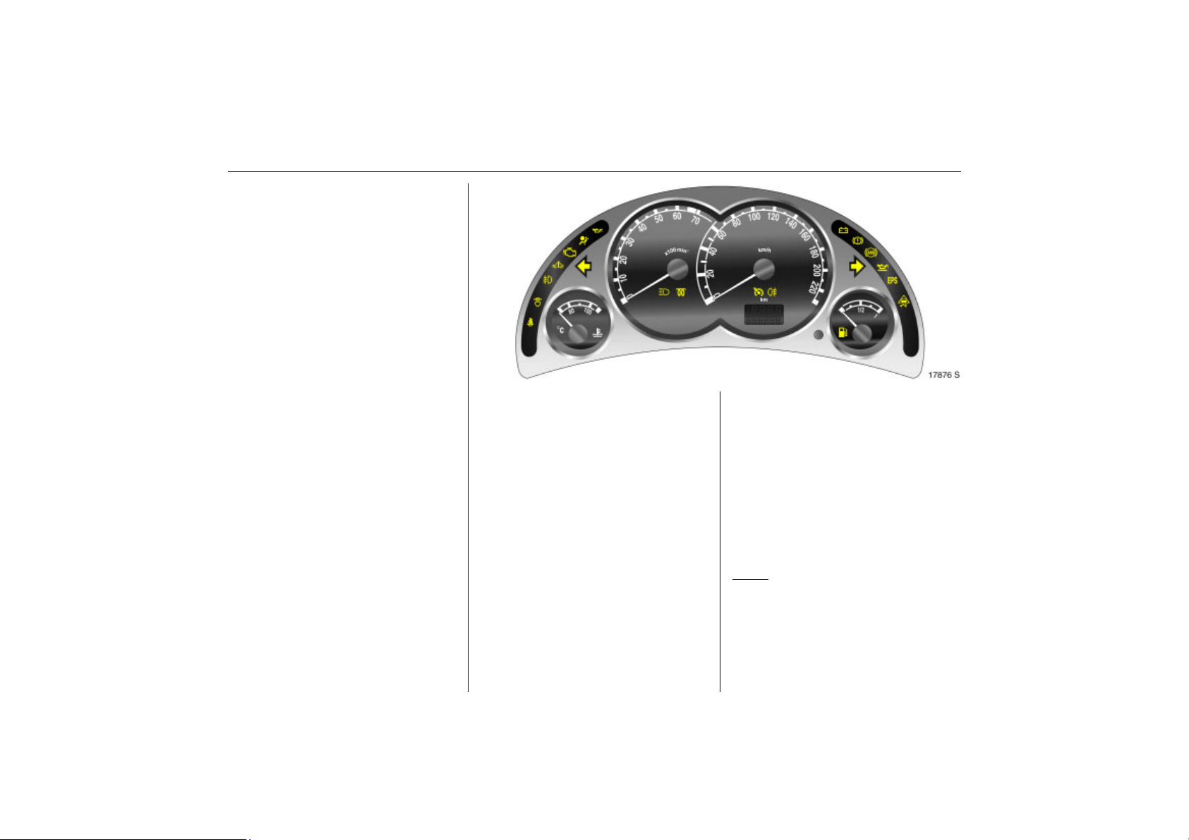
82 Instruments, Controls
Back to overview
Instruments, Controls
Control indicators ................................ 82
Instrument display............................... 87
Information display ............................. 90
Warning buzzers.................................. 100
Windscreen wipers............................... 100
Control indicators
Picture no: 17876s.tif
The control indicators described here are
not present in all vehicles. The description
applies to all instrument versions.
The colours of the control indicators mean:
z Red
z Yellow
z Green
z Blue
Danger, important reminder.
Warning, information, fault.
Switch-on confirmation.
Switch-on confirmation.
X
Picture no:
Seat belt 3
Control indicator lights up red.
This comes on after turning on the ignition
(with warning tone) until the seat belt is
done up.
Fasten seat belt 3 62.
B
Adaptive headlamp 3 (AFL)
Control indicator lights up and/or flashes
yellow.
Lamps
Fault in system. Contact a workshop for
assistance.
Page 89
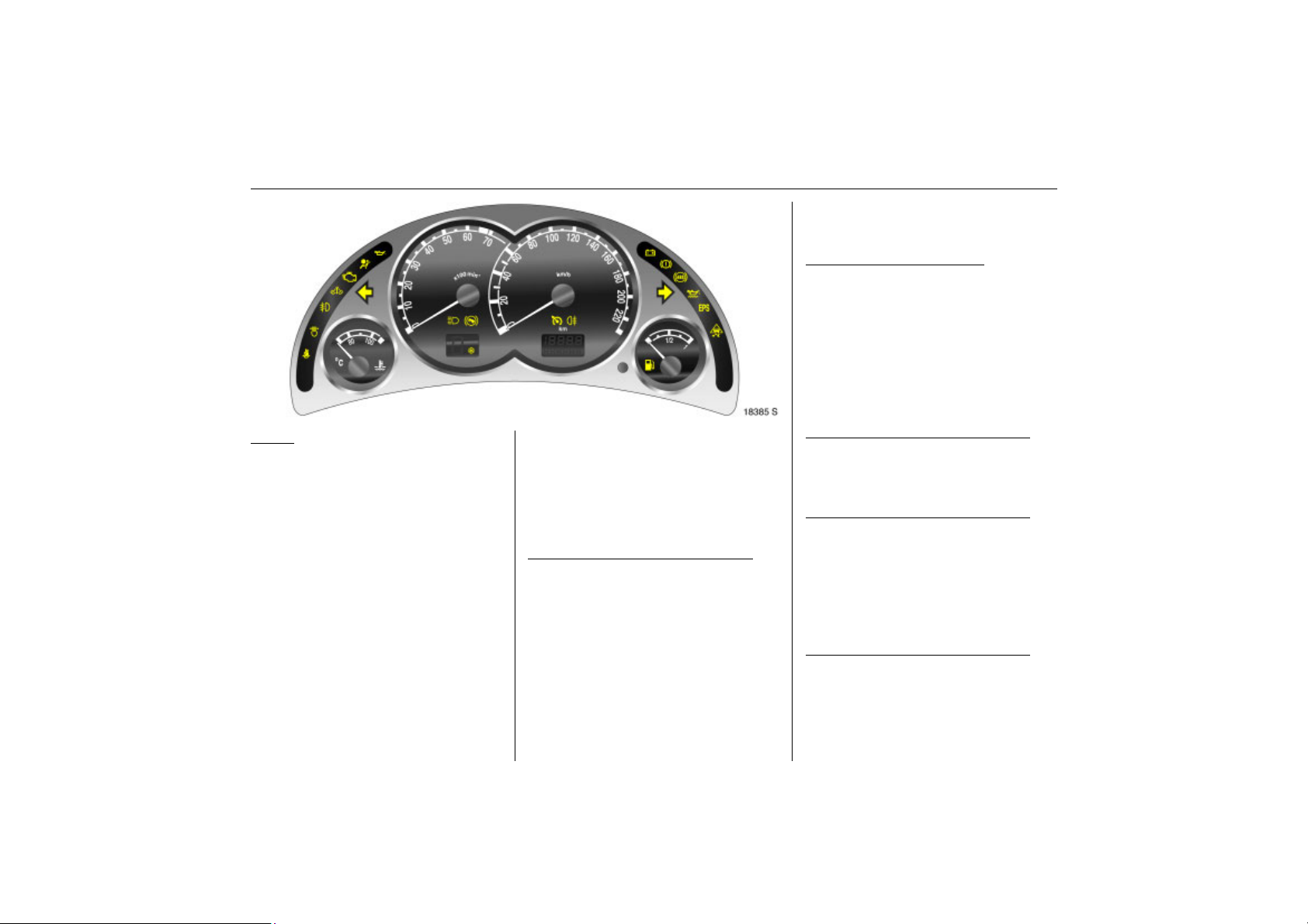
Flashes
Back to overview
System converted to symmetrical dipped
beam.
Control indicator
approximately 4 seconds after the ignition
is switched on as a reminder that the
system has been converted 3 110.
AFL 3 106.
B flashes for
>
Fog lamps 3
Control indicator lights up green.
This comes on when the front fog lamps
are switched on 3 103.
Picture no: 18385s.tif
A
Picture no:
Engine electronics, transmission
electronics, immobiliser, diesel fuel filter 3
Control indicator lights up and/or flashes
yellow.
It illuminates for a few seconds when the
ignition is switched on.
Illuminates when the engine is running
Fault in engine electronics or transmission
electronics. Electronics switches to
emergency running program, fuel
consumption may increase and driveability
of vehicle may be affected 3 143. If the
fault is still there when the engine is started
again, contact a workshop for assistance.
83Instruments, Controls
For vehicles with diesel engine, the diesel
fuel filter may need to be drained of water
3 212.
Flashes when the ignition is on
Fault in the electronic immobiliser system;
the engine cannot be started 3 27.
Z
Exhaust emission
Control indicator lights up and/or flashes
yellow.
It illuminates when the ignition is switched
on and goes out shortly after the engine
starts.
Illuminates when the engine is running
Fault in emission control system. The
permissible emission limits may be
exceeded. Contact a workshop for
assistance immediately.
If it flashes when the engine is running
Fault that could lead to catalytic converter
damage. Ease up on the throttle until the
flashing stops 3 143. Seek the immediate
assistance of a workshop.
v
Airbag systems 3, Belt tensioners
Control indicator lights up red.
Illuminates when the engine is running
Fault in zone of airbag system or belt
tensioners 3 61, 3 72.
Page 90
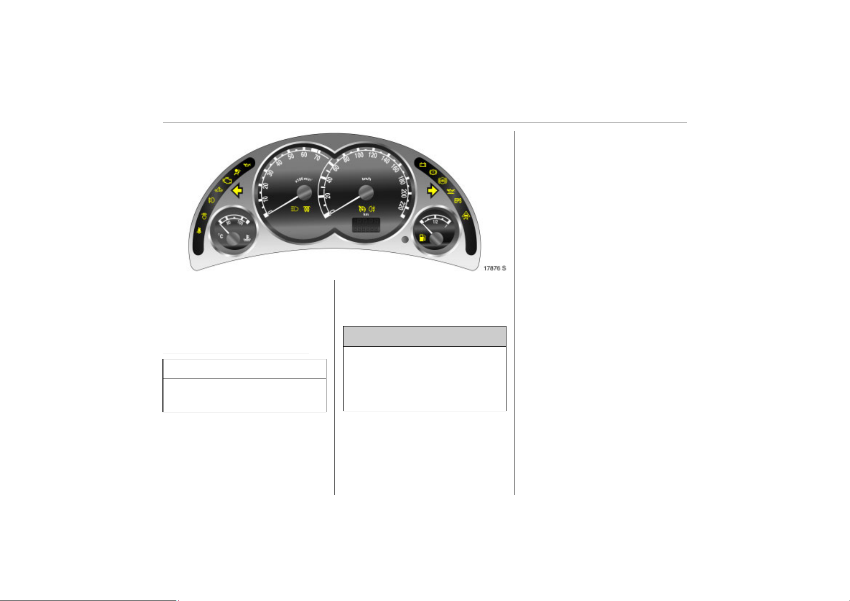
84 Instruments, Controls
Back to overview
Picture no: 17876s.tif
I
Engine oil pressure
Control indicator lights up red
It illuminates when the ignition is switched
on and goes out shortly after the engine
starts.
Illuminates when the engine is running
Caution
Engine lubrication may be interrupted.
This may result in damage to the engine
and/or locking of the drive wheels.
1. Depress clutch.
2. Move gearshift lever to neutral, or with
manual transmission automated 3 place
selector lever in N.
3. Move out of the flow of traffic as quickly
Picture no:
as possible without impeding other
vehicles.
4. Switch off ignition.
9 Warning
When the engine is off, considerably
more force is needed to brake and steer.
Do not remove key until vehicle has
come to a standstill, otherwise the
steering column lock could engage
unexpectedly.
Contact a workshop for assistance.
O
Turn signal lamps
Control indicator flashes green.
The control indicator flashes if a turn signal
or the hazard warning flashers are
activated.
Rapid flashing: failure of a direction
indicator lamp or associated fuse.
Change bulbs 3 185. Fuses 3 182.
C
Main beam
Control indicator lights up blue.
It is illuminated when main beam is on and
during headlamp flash 3 11, 3 102.
j
Automatic transmission 3, start engine.
Control indicator lights up yellow.
The engine can only be started if the foot
brake is depressed. If the foot brake is not
depressed, the control indicator illuminates
3 130.
Page 91
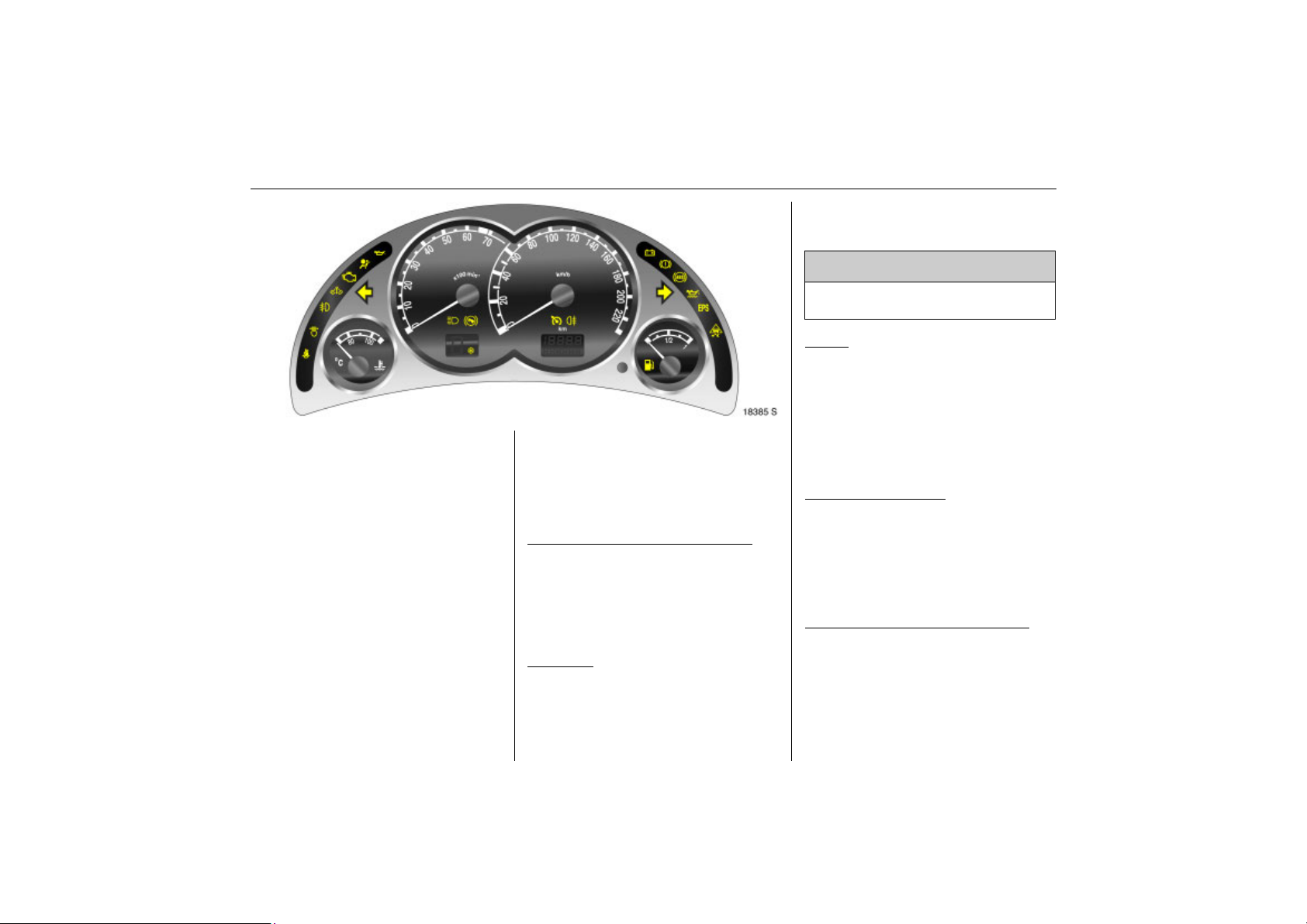
T
Back to overview
Picture no: 18385s.tif
Winter mode for manual transmission
automated 3
Control indicator lights up yellow.
Control indicator lights up when winter
program is enabled 3 132.
m
Cruise control 3
Control indicator lights up green
This comes on when the system is switched
on 3 148.
r
Fog tail lamp
Control indicator lights up yellow.
This comes on when the fog tail lamp is
switched on 3 104.
p
Picture no:
Alternator
Control indicator lights up red.
It illuminates when the ignition is switched
on and goes out shortly after the engine
starts.
Illuminates when the engine is running
Stop, switch off engine. Battery is not
charging. Contact a workshop
immediately.
R
Brake system, clutch system
Control indicator lights up or flashes red.
Illuminated
Illuminates when the ignition is switched on
if the hand brake is applied 3 151.
85Instruments, Controls
Lights up when the hand brake is released
when the fluid level for the brake or clutch
systems is low 3 214.
9 Warning
Stop. Do not continue your journey.
Consult a workshop.
Flashes
On vehicles with manual transmission
automated 3, control indicator R flashes
for a few seconds after the ignition is
switched off when the hand brake has not
been applied.
u
Anti-lock brake system
Control indicator lights up red.
Illuminates while driving
Fault in anti-lock braking system 3 152.
S
Engine oil level 3
Control indicator lights up yellow.
The engine oil level is checked
automatically 3.
Illuminates when the engine is running
Engine oil level too low. Check engine oil
level and top up engine oil if necessary
3 210.
Page 92
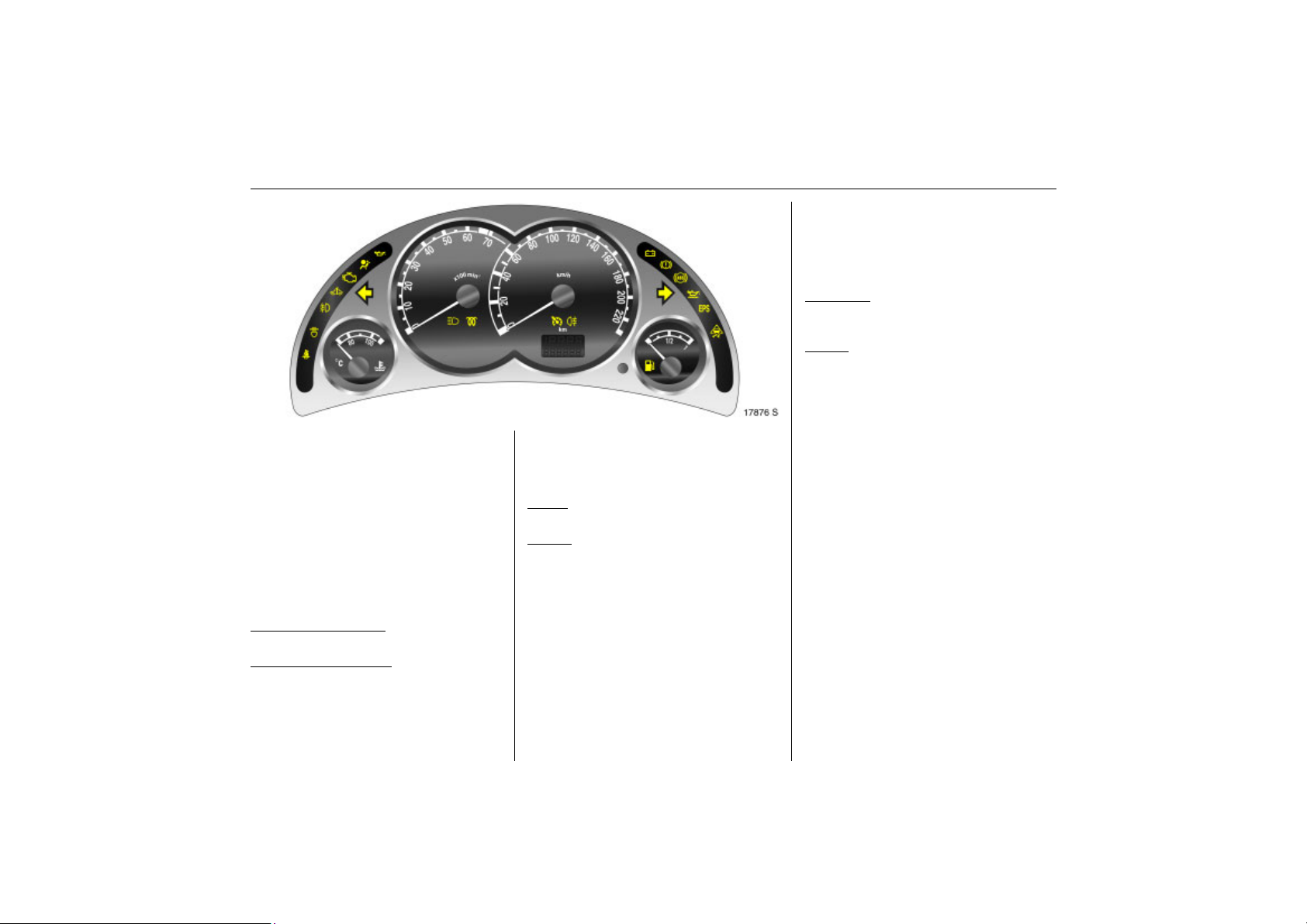
86 Instruments, Controls
Back to overview
Picture no: 17876s.tif
1)
EPS
Electric power steering
Control indicator lights up yellow.
Fault in electrical power steering. Vehicle
can still be driven, but greater force is
required for steering. Contact a workshop
immediately.
v
Electronic Stability Program (ESP®
Control indicator flashes or lights up
yellow.
Flashing during driving
System engages 3 146.
Illuminates while driving
Fault in system 3 146.
Plus
) 3
Y
Picture no:
Fuel level
Control indicator lights up and/or flashes
yellow.
Lamps
Level in fuel tank too low.
Flashes
Fuel level is used up, fuel immediately.
Never let the tank run dry!
Erratic fuel supply can cause catalytic
converter to overheat 3 142.
Diesel engines: Bleed the fuel system after
running empty 3 165.
!
Preheating system 3, Diesel particle
filter 3
Control indicator lights up and/or flashes
yellow.
Illuminated
Preheating activated. Only activates when
outside temperatures are low.
Flashes
(in vehicles with diesel particle filter)
Control indicator ! flashes if the filter
requires cleaning and previous driving
conditions did not permit automatic
cleaning. Continue driving and if possible
do not allow engine speed to drop
below 2000 rpm.
The control indicator ! goes off as soon
as the self-cleaning operation is complete.
Diesel particle filter 3 144.
1)
EPS = Electric Power Steering.
Page 93
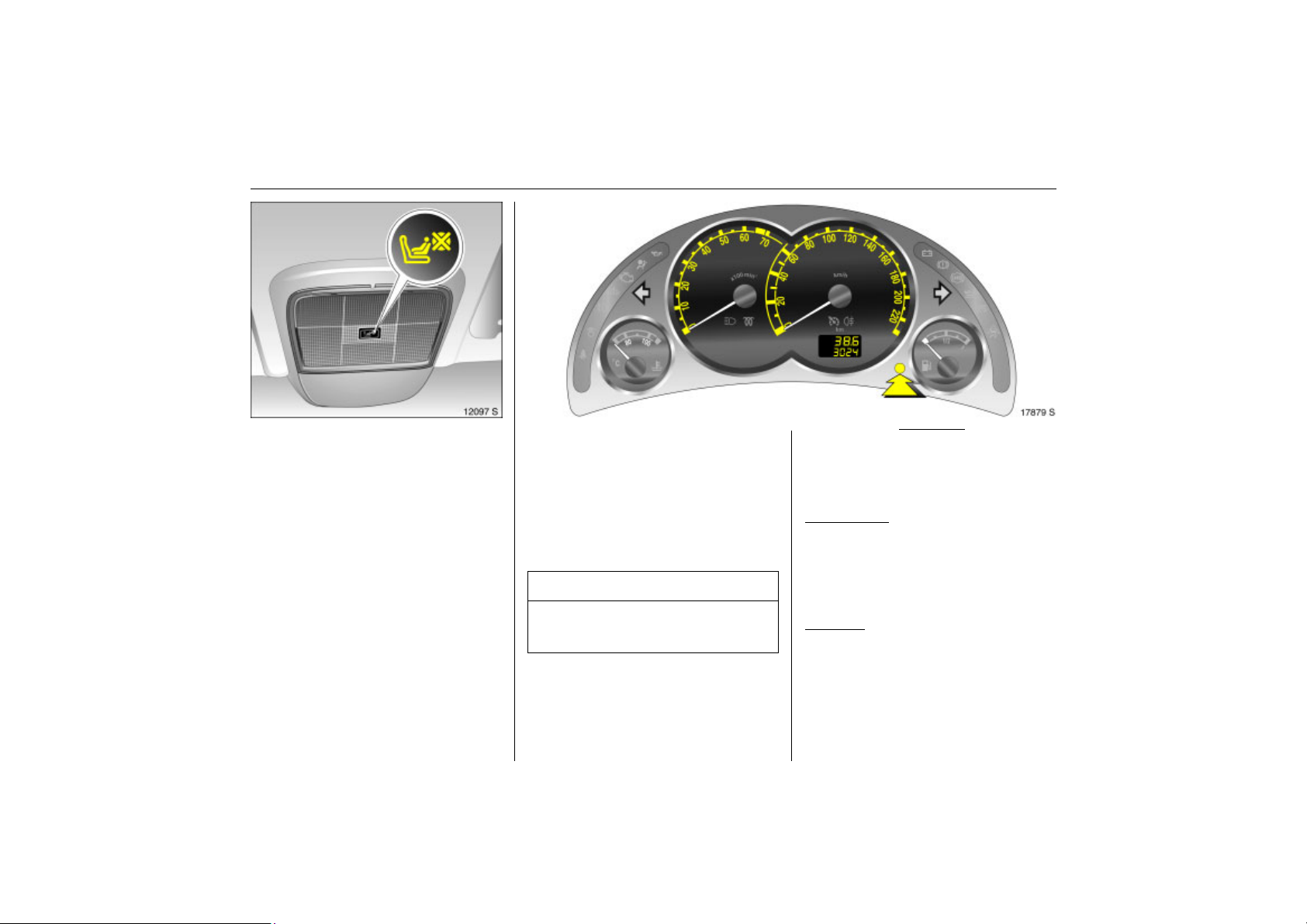
87Instruments, Controls
Back to overview
y
Picture no: 12097s.tif
Seat occupancy recognition 3
3 67, 3 72.
Instrument display
Picture no: 17879s.tif
In some versions, the indicators of the
instruments briefly rotate to the end
position when the ignition is switched on.
Tachometer
Displays the engine rpm.
Drive in a low engine speed range for each
gear as much as possible.
Caution
If the pointer is in the warning zone, the
maximum permitted engine speed is
exceeded. Engine at risk.
Speedometer
Speed display.
Kilometre display
Picture no:
If the ignition is off the mileage is displayed
for approx. 15 seconds by briefly pressing
the reset knob.
Top line:
Trip odometer
Displays the number of kilometres since the
gauge was reset.
To reset, hold the reset knob depressed for
a few seconds with the ignition on.
Bottom line:
Odometer
Records the number of kilometres.
Maintenance, Inspection system, 3 89,
3 208.
Page 94
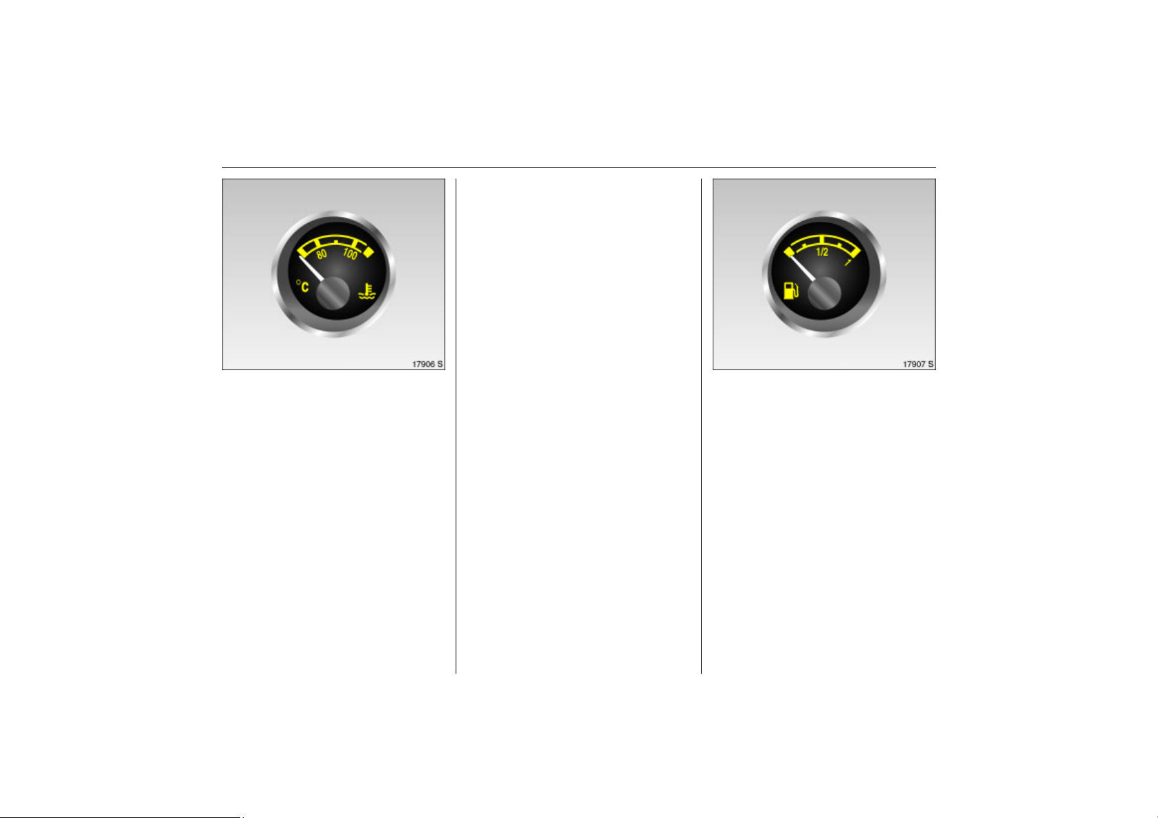
88 Instruments, Controls
Back to overview
For physical reasons, the engine
temperature gauge shows the coolant
temperature only if the coolant level is
adequate.
During operation the system is pressurised.
The temperature may therefore rise briefly
to over 100 C.
Coolant temperature display
Picture no: 17906s.tif
Coolant temperature display
Pointer in zone at
left
Pointer between
the zones
Pointer in zone at
right (warning
zone)
= Engine operating
temperature not yet
reached.
= Normal operating
temperature.
= Temperature too
high: Stop vehicle
and switch off
engine. Danger to
engine. Check
coolant level
immediately 3 213.
Fuel gauge
Picture no: 17907s.tif
Fuel tank level display.
If the fuel level is too low, a warning lamp
lights up Y. When the light flashes, refuel as
soon as possible.
Never run the tank dry!
Because of the fuel remaining in the tank,
the amount of fuel required to fill the
tank may be less than the specified tank
capacity.
Page 95
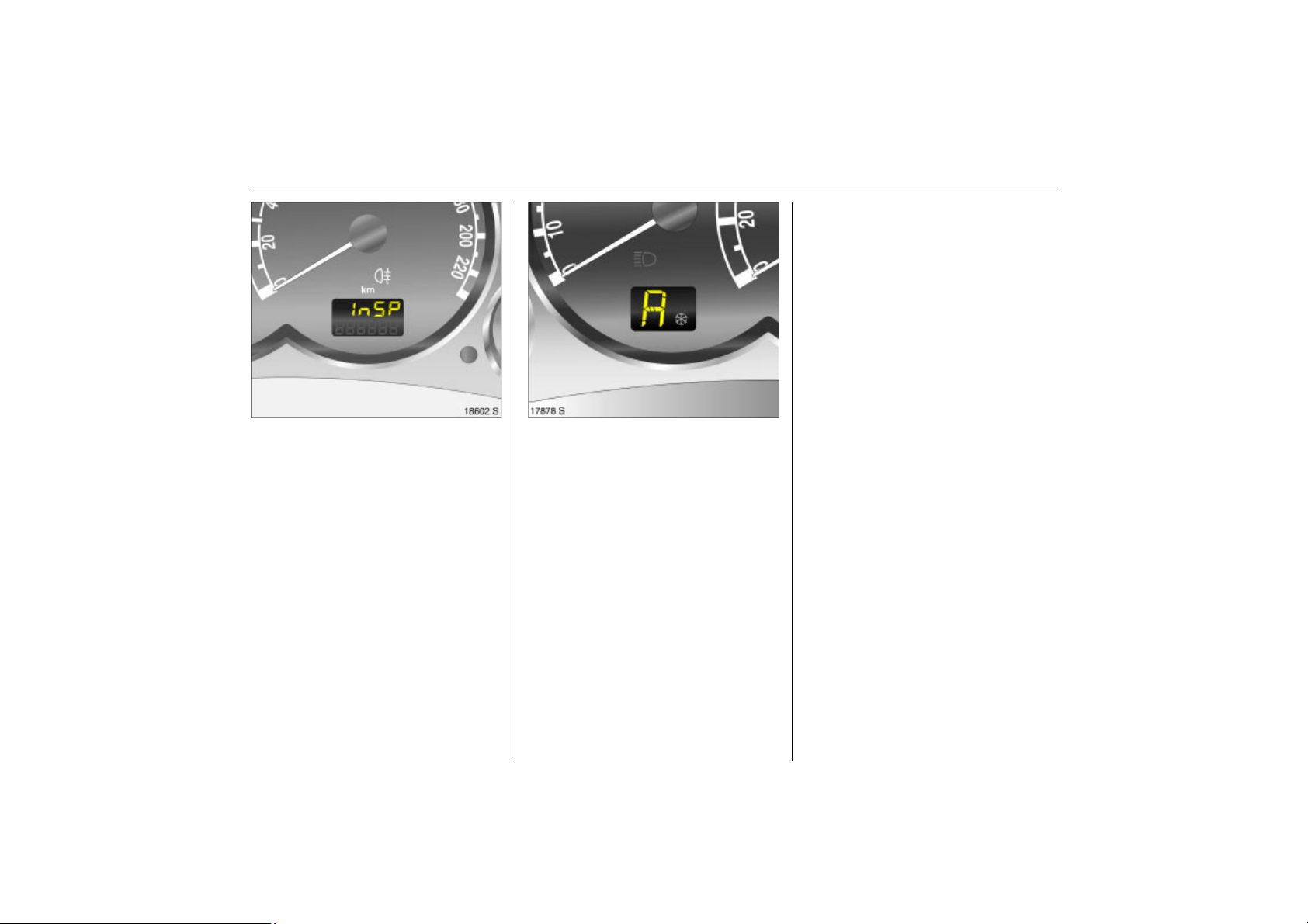
89Instruments, Controls
Back to overview
R Reverse gear.
N Neutral.
A Manual transmission automated
automatic mode.
1-5 Manual mode, current gear in
manual transmission automated.
Automated manual transmission 3 3 129.
Service Display 3
Picture no: 18602s.tif
When the InSP indicator in the odometer
display comes on, make a service
appointment with a workshop as soon as
possible.
Maintenance, Inspection system, 3 208.
Transmission display 3
Picture no: 17878s.tif
Display of current gear or mode with
manual transmission automated 3.
Page 96
90 Instruments, Controls
Back to overview
12:01 17,0°C
FM 3 90,6MHz
REG AS RDS TP
Ü Board Computer 19,5° 19:36
BC 1 All values
BC 2
Timer
1
8
257.0 km
Ø40km/h
31.0 Ltr.
Ø 7.0 Ltr./100km
Some information appears in the display in
an abbreviated form.
Picture no: 17913s.tif
Information display
Triple information display 3
Display of time, outside temperature and
date/infotainment system (when it is on).
When the ignition is off, the time, date and
outside temperature can be shown by
briefly pressing one of the two buttons next
to the display.
Graphical information display 3, Colour
Picture no: 16719t.tif
information display 3
Display of time, outside temperature and
date/infotainment system (when it is on).
The colour information display presents the
information in colour.
The type of information and how it is
displayed depend on the equipment of the
vehicle and the settings made.
Page 97
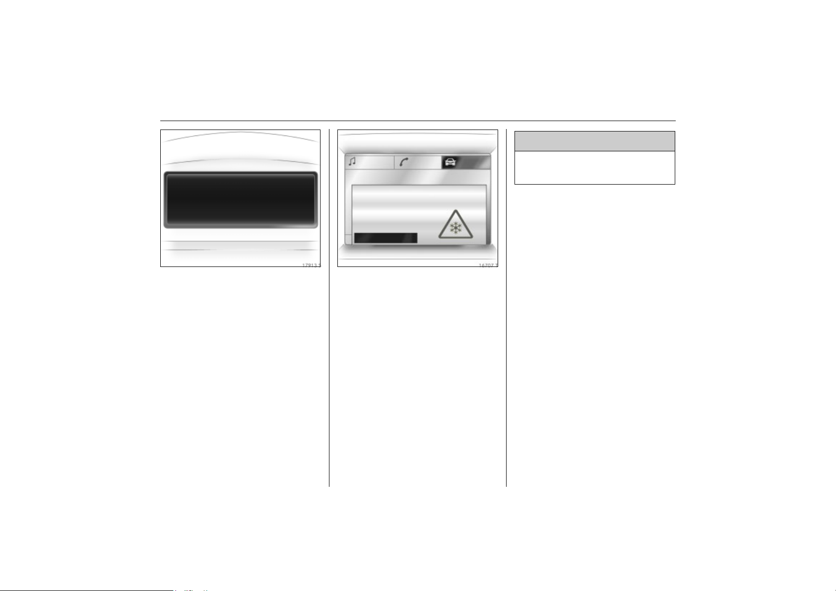
8:56 -5,5°C
Back to overview
07.04.2004
91Instruments, Controls
9 Warning
Caution: The road surface may already
be icy even though the display indicates
:
a few degrees above 0 C.
Slippery road
-2,5°C
OK
Picture no: 17913s.tif
Outside temperature
A fall in temperature is indicated
immediately and a rise in temperature
after a time delay.
If outside temperature drops below 3 C,
the symbol : appears in the triple
information display as a warning for icy
road conditions. When temperature
increases to at least 5 C, the : symbol
goes out.
In vehicles with graphical information
Picture no: 16707t.tif
display 3 or colour information display 3, a
warning message Slippery road appears
on the display as a warning for icy road
surfaces. There is no message below -5 C.
Page 98
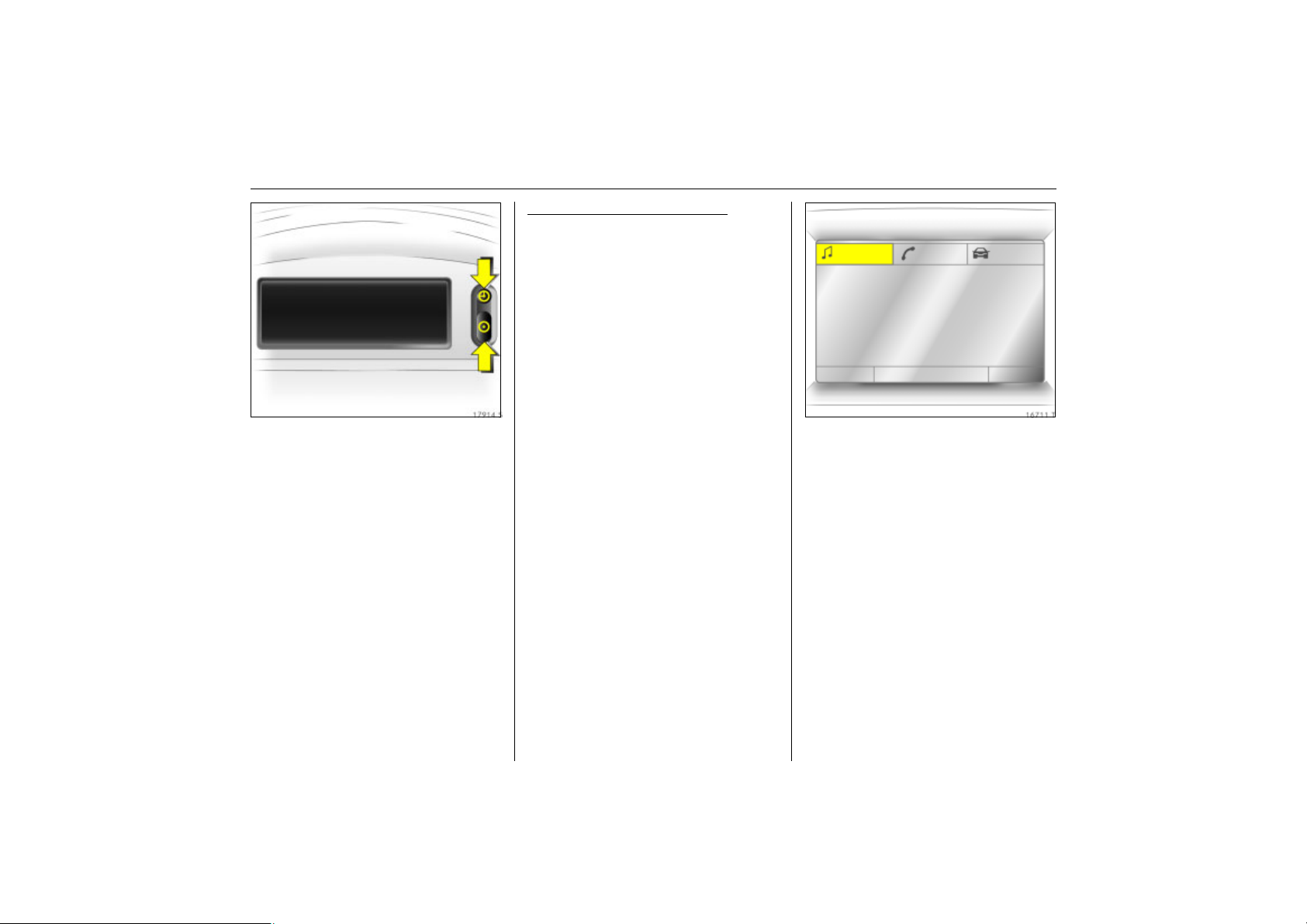
92 Instruments, Controls
Back to overview
8:56 5,5°C
07.04.2004
Picture no: 17914s.tif
Triple information display
Set date and time
The infotainment system 3 must be off.
Activate setting mode by holding the Ö
button depressed for about 2 seconds. The
flashing value is adjusted using the ;
button. The Ö button is used to switch to
the next unit and to exit setting mode.
Automatic time synchronisation
The RDS signal of most VHF transmitters
automatically sets the time. This can be
identified by } in the display.
Some transmitters do not send a correct
time signal. In such cases, we recommend
that you switch off automatic time
synchronisation.
Activate setting mode and set it to year
setting. Hold the Ö button depressed
about 3 seconds until } flashes in the
display and “RDS TIME" appears. The
function is activated (RDS TIME 1) or
deactivated (RDS TIME 0) with the ;
button. Exit setting mode using the Ö
button.
3
FM AS [TP] REG CDin MP3
90.6
MHz
19,5° 19:36
Picture no: 16711t.tif
Graphical information display 3
or colour information display 3,
selecting functions
Functions and their menus are depicted in
the graphical information display and
colour information display.
These functions are marked or executed in
the menu display via the cross switch, the
multifunction knob 3 on the Infotainment
System or buttons 3 on the steering wheel.
Page 99
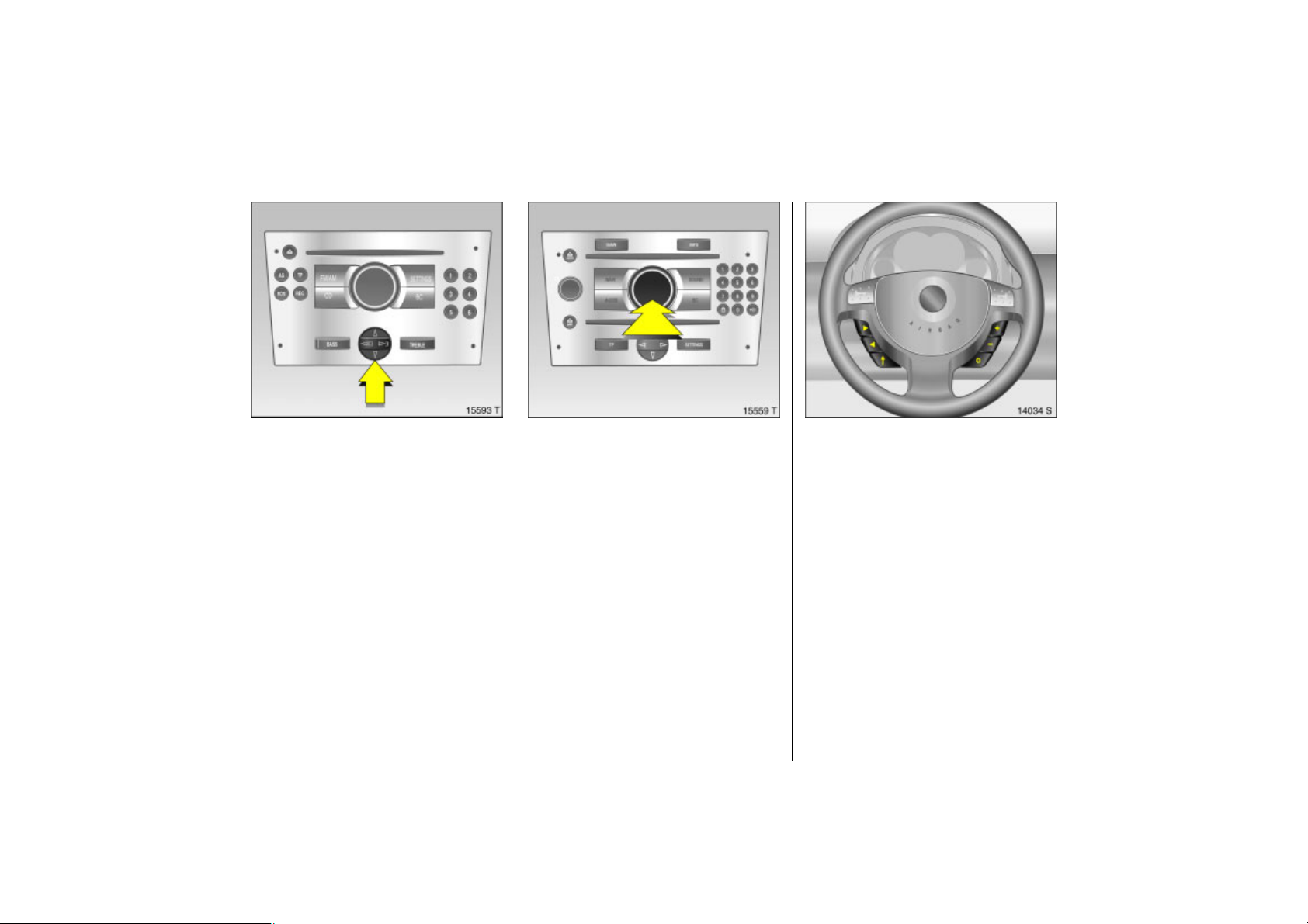
93Instruments, Controls
Back to overview
To select with four-way button
Picture no: 15593t.tif
Select menu items via menus and with the
buttons/four-way button of the
Infotainment system.
Selection with the multifunction knob 3
Picture no: 15559t.tif
Turn the multifunction button to highlight
menu items or commands and to select
function areas.
Press the multifunction button to select the
highlighted item or confirm a command.
To exit a menu, turn the multifunction
button left or right to Return or Main and
select.
Selection using buttons 3 on steering
Picture no: 14034s.tif
wheel
Select menu options via menus and with
the buttons.
Page 100
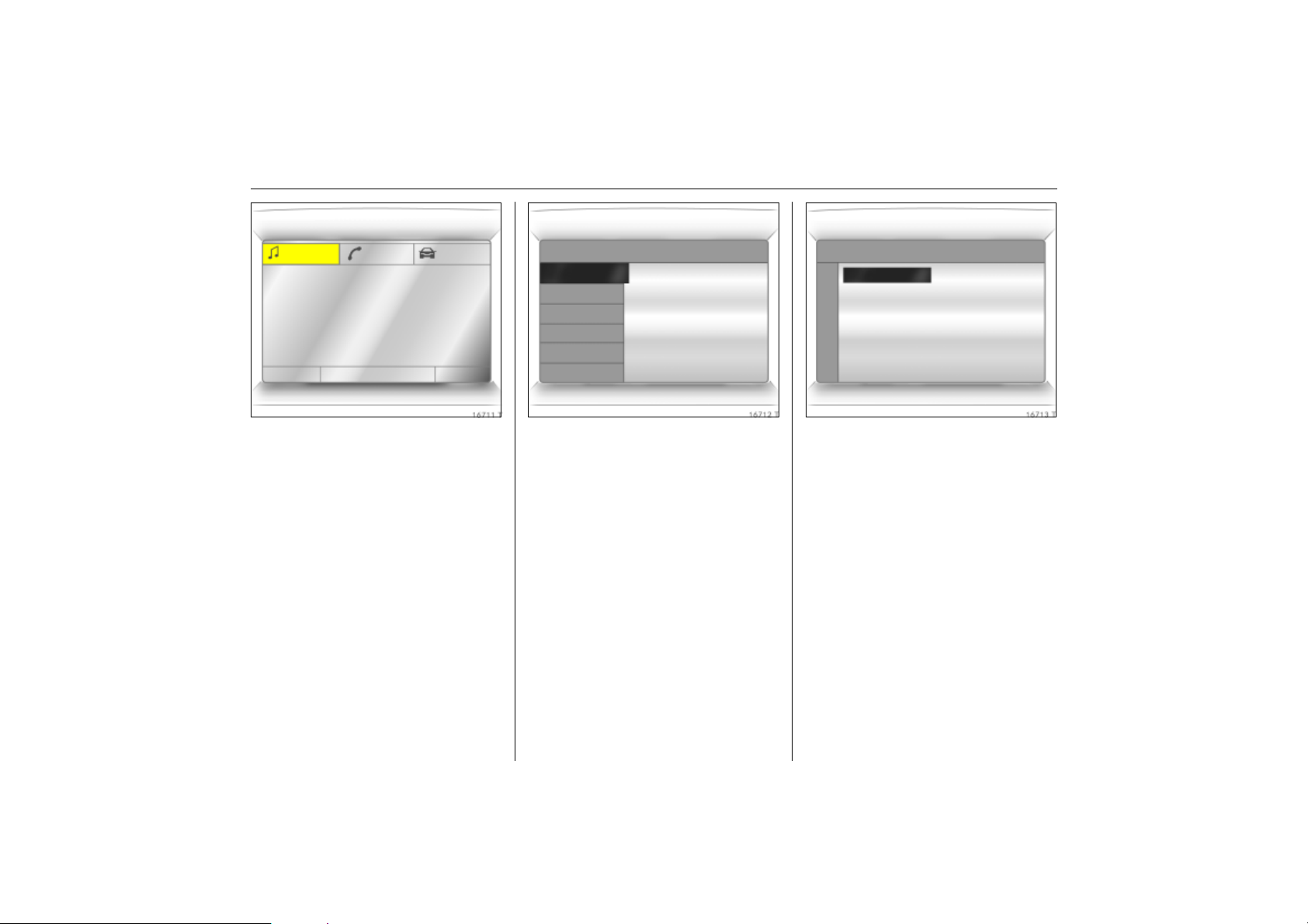
94 Instruments, Controls
Back to overview
FM AS [TP] REG CDin MP3
90.6
MHz
19,5° 19:36
Picture no: 16711t.tif
Function areas
For each functional area there is a main
page (Main), which is selected at the top
edge of the display (not with the
Infotainment system CD 30 or the Mobile
Phone Portal):
z Audio.
z Navigation 3.
z Telephone 3.
z Trip computer 3.
For Audio, Navigation 3 and Telephone 3
functions – see infotainment system
instructions.
7 Settings 19,5° 19:36
Time, Date 19:36
Language
Units 10 . 07 . 2004
Contrast
Day / Night
! Ign. logic
Picture no: 16712t.tif
System settings
The settings are accessed via the
Settings menu.
Press the Main button 3 (not found on all
infotainment systems) on the infotainment
system (call up main display).
Press the Settings button of the
infotainment system. On Infotainment
System CD 30, make sure no menu has
been selected.
The Settings menu is displayed.
7 Time, Date 19,5° 19:36
Time 19:36
Date 10 . 07 . 2004
! Synchron. clock automatical.
Picture no: 16713t.tif
Setting date and time 3
Select menu item Time, Date, from the
Settings menu.
The menu for Time, Date is displayed.
Select the required menu item and make
setting.
 Loading...