

Page 1
Owner's Manual
Page 2

Page 3

Contents
Introduction .................................... 2
In brief ............................................ 6
Keys, doors and windows ............ 21
Seats, restraints ........................... 47
Storage ........................................ 72
Instruments and controls ............. 91
Lighting ...................................... 135
Climate control ........................... 146
Driving and operating ................. 156
Vehicle care ............................... 229
Service and maintenance .......... 278
Technical data ........................... 282
Customer information ................ 298
Index .......................................... 310
Page 4
2 Introduction
Introduction
Page 5

Introduction 3
Vehicle specific data
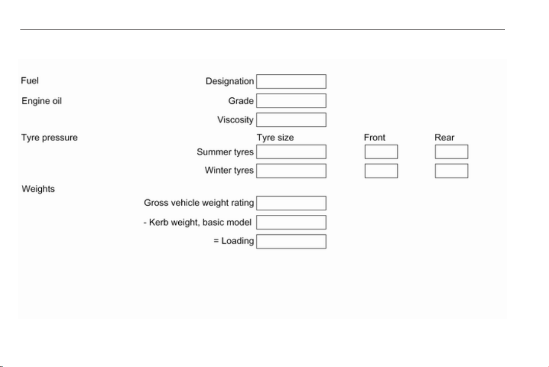
Please enter your vehicle's data on
the previous page to keep it easily
accessible. This information is
available in the sections "Service and
maintenance" and "Technical data"
as well as on the identification plate.
Introduction
Your vehicle is a designed
combination of advanced technology,
safety, environmental friendliness
and economy.
This Owner's Manual provides you
with all the necessary information to
enable you to drive your vehicle
safely and efficiently.
Make sure your passengers are
aware of the possible risk of accident
and injury which may result from
improper use of the vehicle.
You must always comply with the
specific laws and regulations of the
country that you are in. These laws
may differ from the information in this
Owner's Manual.
Disregarding the description given in
this manual may affect your warranty.
When this Owner's Manual refers to a
workshop visit, we recommend your
Opel Service Partner.
For gas vehicles we recommend an
Opel Repairer authorised for
servicing gas vehicles.
All Opel Service Partners provide
first-class service at reasonable
prices. Experienced mechanics
trained by Opel work according to
specific Opel instructions.
The customer literature pack should
always be kept ready to hand in the
vehicle.
Using this manual
● This manual describes all options
and features available for this
model. Certain descriptions,
including those for display and
menu functions, may not apply to
your vehicle due to model
variant, country specifications,
special equipment or
accessories.
● The "In brief" section will give you
an initial overview.
● The table of contents at the
beginning of this manual and
within each section shows where
the information is located.
● The index will enable you to
search for specific information.
● This Owner's Manual depicts lefthand drive vehicles. Operation is
similar for right-hand drive
vehicles.
● The Owner's Manual uses the
engine identifier code. The
corresponding sales designation
and engineering code can be
found in the section "Technical
data".
● Directional data, e.g. left or right,
or front or back, always relate to
the direction of travel.
● Displays may not support your
specific language.
● Display messages and interior
labelling are written in bold
letters.
Page 6

4 Introduction
Danger, Warnings and
Cautions
9 Danger
Text marked 9 Danger provides
information on risk of fatal injury.
Disregarding this information may
endanger life.
9 Warning
Text marked 9 Warning provides
information on risk of accident or
injury. Disregarding this
information may lead to injury.
Caution
Text marked Caution provides
information on possible damage to
the vehicle. Disregarding this
information may lead to vehicle
damage.
Symbols
Page references are indicated with 3.
3 means "see page".
Page references and index entries
refer to the indented headings given
in the section table of content.
Chronological order to select menu
entries in the vehicle personalisation
is indicated with I.
We wish you many hours of
pleasurable driving.
Your Opel Team
Page 7

Introduction 5
Page 8
6 In brief
In brief
Initial drive information
Vehicle unlocking
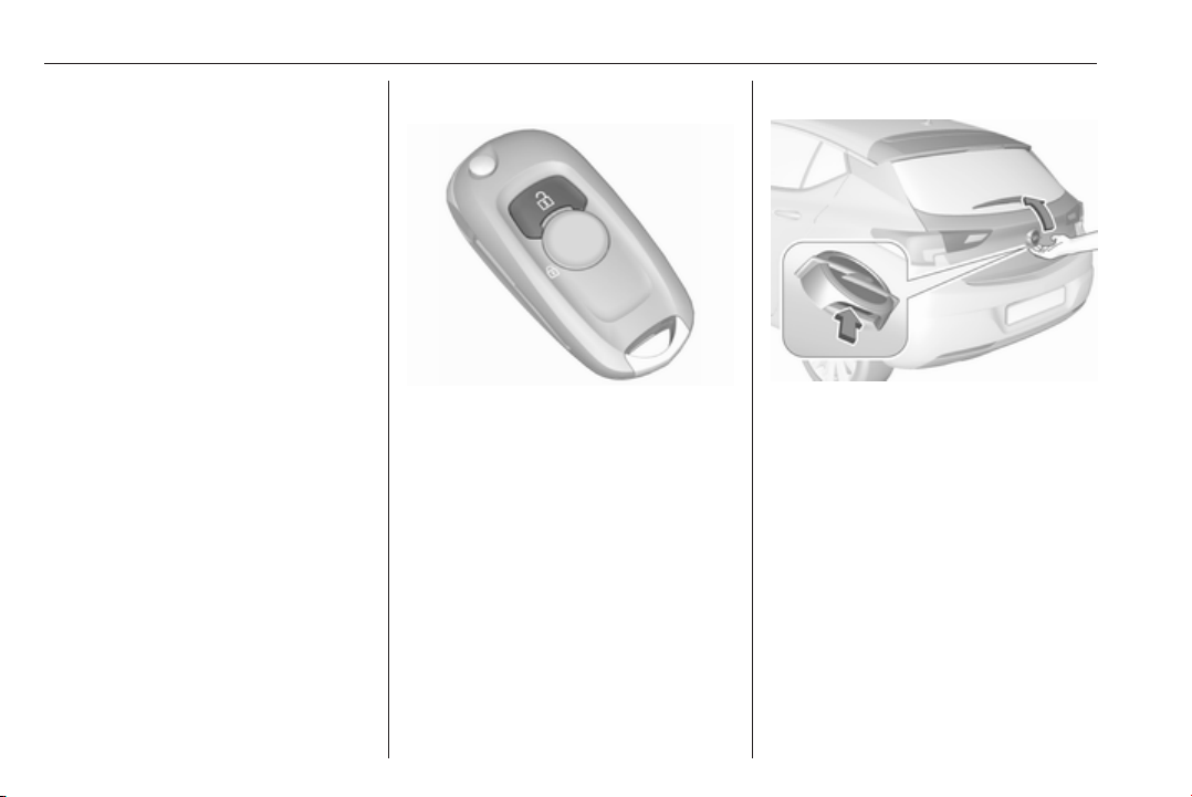
c to unlock the doors and load
Press
compartment. Open the doors by
pulling the handles.
Tailgate
5-door Hatchback: to open the
tailgate, push the touchpad switch
below the brand emblem.
Sports Tourer: to open the tailgate,
push the touchpad switch under the
tailgate moulding.
Radio remote control 3 22.
Central locking system 3 25.
Electronic key system 3 23.
Load compartment 3 31.
Page 9
In brief 7
Seat adjustment
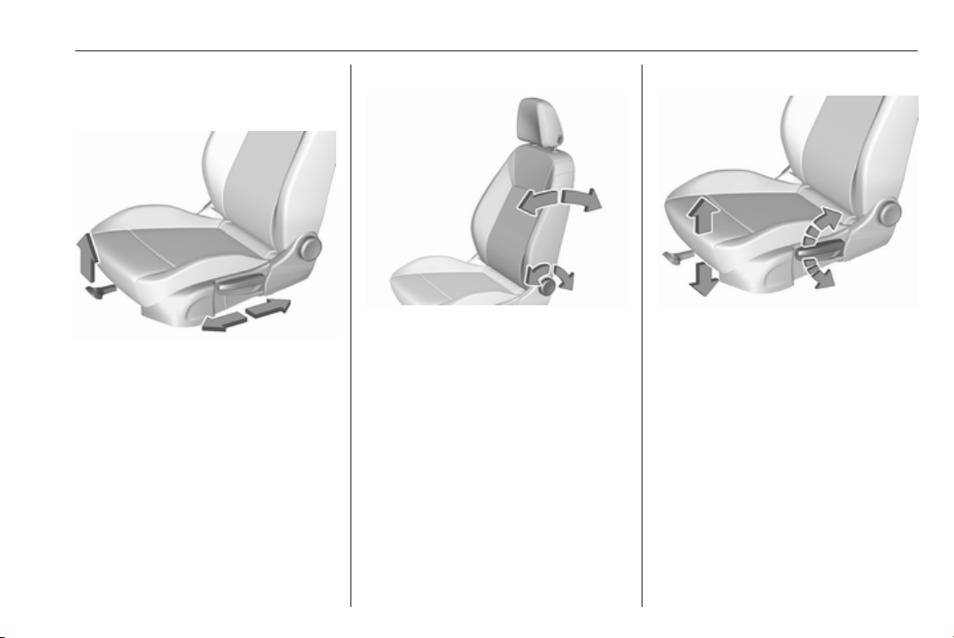
Longitudinal adjustment
Pull handle, slide seat, release
handle. Try to move the seat back and
forth to ensure that the seat is locked
in place.
Seat position 3 48.
Manual seat adjustment 3 49.
Power seat adjustment 3 51.
Backrests inclination
Turn handwheel. Do not lean on
backrest when adjusting.
Seat position 3 48.
Manual seat adjustment 3 49.
Power seat adjustment 3 51.
Seat height
Lever pumping motion
up : seat higher
down : seat lower
Seat position 3 48.
Manual seat adjustment 3 49.
Power seat adjustment 3 51.
Page 10
8 In brief
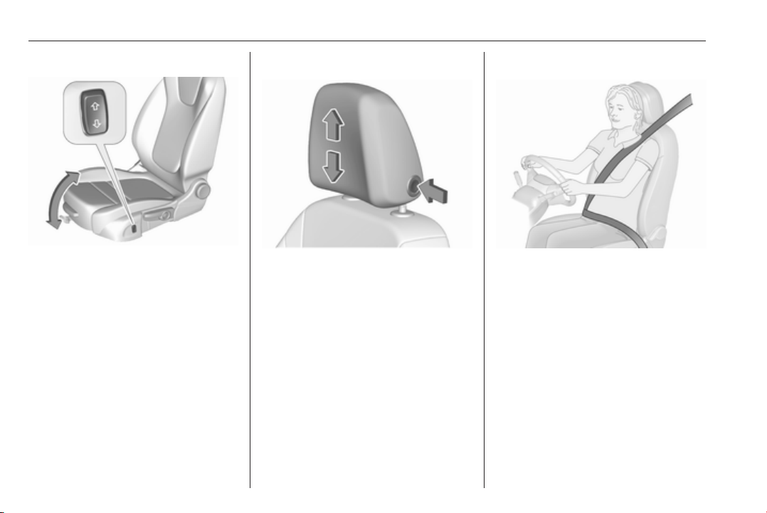
Seat inclination
Press switch
top : front end higher
bottom : front end lower
Seat position 3 48.
Manual seat adjustment 3 49.
Power seat adjustment 3 51.
Head restraint adjustment
Press release button, adjust height,
engage.
Head restraints 3 47.
Seat belt
Pull out the seat belt and fasten in belt
buckle. The seat belt must not be
twisted and must fit close against the
body. The backrest must not be tilted
back too far (maximum approx. 25°).
To unfasten belt, press red button on
belt buckle.
Seat position 3 48, Seat belts
3 57, Airbag system 3 59.
Page 11
In brief 9
Mirror adjustment
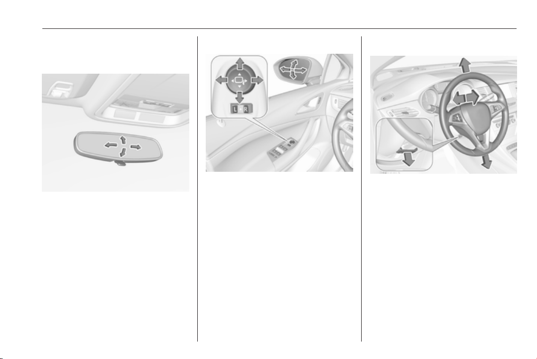
Interior mirror
To adjust the mirror, move the mirror
housing in the desired direction.
Manual anti-dazzle interior mirror
3 41.
Automatic anti-dazzle interior mirror
3 42.
Exterior mirrors
Select the relevant exterior mirror by
switching the rocker control to left
mirror (L) or right mirror (R). Adjust
respective mirror by the four-way
control.
Convex exterior mirrors 3 40,
Electric adjustment 3 40, Folding
exterior mirrors 3 40.
Heated exterior mirrors 3 41.
Steering wheel adjustment
Unlock the lever, adjust the steering
wheel, then engage the lever and
ensure it is fully locked.
Do not adjust the steering wheel
unless the vehicle is stationary and
the steering wheel lock has been
released.
Airbag system 3 59, Ignition
positions 3 157.
Page 12
10 In brief
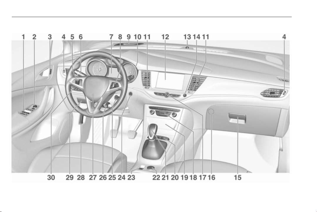
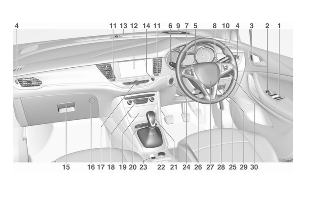
Instrument panel overview
Page 13

In brief 11
1 Power windows ..................... 42
2 Exterior mirrors ..................... 40
3 Central locking system .......... 25
4 Side air vents ...................... 154
5 Cruise control ..................... 184
Speed limiter ....................... 186
Adaptive cruise control .......187
Forward collision alert ......... 195
6 Turn and lane-change
signals, headlight flash,
low/high beam, high beam
assist ................................... 141
Exit lighting ......................... 144
Parking lights ...................... 142
Buttons for Driver
Information Centre .............. 115
7 Instruments ........................ 103
Driver Information Centre .... 115
8 Buttons for Driver
Information Centre .............. 115
9 Forward collision alert
indicator ............................. 195
10 Windscreen wiper and
washer, rear wiper and
washer ................................. 93
11 Centre air vents ................... 154
12 Info Display ......................... 121
13 Anti-theft alarm system
status LED ........................... 37
14 Hazard warning flashers ....140
15 Glovebox .............................. 72
16 CD player
17 Controls for Info Display
operation ............................. 121
18 Climate control system ........ 147
19 Fuse box ............................ 250
20 Traction Control system .....181
Electronic Stability Control . 182
Sport mode ........................ 183
Parking assist / Advanced
parking assist ..................... 201
Lane keep assist ................ 216
Eco button for stop-start
system ................................. 162
Fuel selector ....................... 105
21 Manual transmission .......... 174
Automatic transmission ...... 171
Manual transmission
automated ........................... 175
22 Power outlet .......................... 98
23 Parking brake ...................... 179
24 Power button ....................... 158
25 Ignition switch ..................... 157
26 Steering wheel adjustment ..92
27 Horn ..................................... 93
28 Bonnet release lever .......... 231
29 Storage compartment ........... 73
30 Light switch ........................ 135
Headlight range
adjustment ......................... 136
Front/rear fog lights ............ 141
Instrument illumination ....... 143
Page 14
12 In brief
Page 15
In brief 13
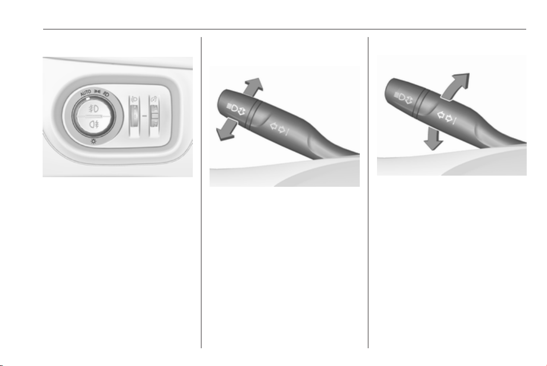
Exterior lighting
AUTO : automatic light control
switches automatically
between daytime running
light and headlight
: sidelights
8
: headlights
9
Automatic light control 3 136.
Fog lights
Press button in light switch:
: front fog lights
>
ø
: rear fog light
Headlight flash, high beam and low beam
headlight flash : pull lever
high beam : push lever
low beam : push or pull lever
High beam 3 136.
Headlight flash 3 136.
LED headlights 3 137.
High beam assist 3 137.
Turn and lane-change signals
lever up : right turn signal
lever down : left turn signal
Turn and lane-change signals
3 141, Parking lights 3 142.
Page 16

14 In brief
Hazard warning flashers
Operated by pressing ¨.
Hazard warning flashers 3 140.
Horn
Press j.
Washer and wiper systems
Windscreen wiper
HI : fast
LO : slow
INT : interval wiping
or
automatic wiping with rain
sensor
OFF : off
For single wipe when the wiper is off,
press lever down to position 1x.
Windscreen wiper 3 93.
Page 17

In brief 15
Windscreen washer
Pull lever.
Windscreen washer system 3 93,
Washer fluid 3 234, Wiper blade
replacement 3 236.
Rear window wiper
Turn outer cap to activate the rear
window wiper:
OFF : off
INT : intermittent operation
ON : continuous operation
Rear window washer
Push lever.
Washer fluid is sprayed on the rear
window and the wiper wipes a few
times.
Rear window wiper/washer 3 95.
Page 18
16 In brief
Climate control
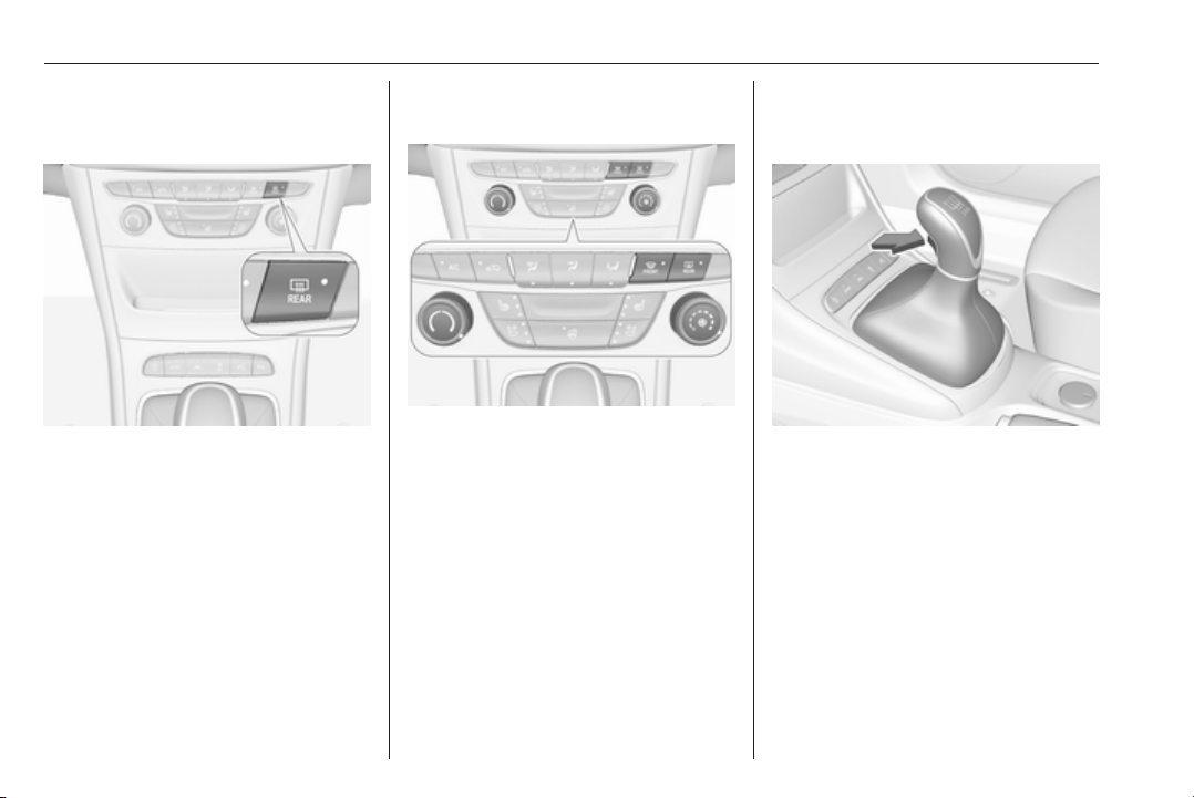
Heated rear window
The heating is operated by pressing
Ü.
Heated rear window 3 44.
Heated exterior mirrors
Pressing Ü also activates the heated
exterior mirrors.
Heated exterior mirrors 3 41.
Demisting and defrosting the windows
●
Press V: the air distribution is
directed towards the windscreen.
● Set fan speed to highest level.
● Set temperature control to
warmest level.
●
Switch on heated rear window Ü.
● Open side air vents as required
and direct them towards the door
windows.
Heating and ventilation system
3 146.
Air conditioning system 3 147.
Transmission
Manual transmission
Reverse: with the vehicle stationary,
depress clutch pedal and press the
release button on the selector lever
and engage the gear.
Manual transmission 3 174.
Page 19
In brief 17
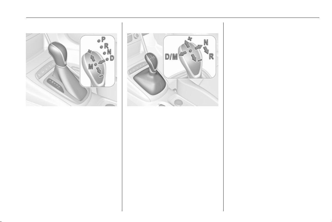
Automatic transmission
P : park position
R : reverse
N : neutral mode
D : automatic mode
M : manual mode
: upshift
<
: downshift
]
The selector lever can only be moved
out of P when the ignition is on and
the brake pedal is applied. To engage
P or R, press the release button.
Automatic transmission 3 171.
Manual transmission automated
N : neutral position
D : automatic mode
M : manual mode
: upshift
<
: downshift
]
R : reverse
Engage reverse only when
vehicle is stationary.
Manual transmission automated
3 175.
Starting off
Check before starting off
● tyre pressure and condition
3 256, 3 295
● engine oil level and fluid levels
3 232.
● all windows, mirrors, exterior
lighting and number plates are
free from dirt, snow and ice and
are operational
● proper position of mirrors 3 40,
seats 3 48 and seat belts
3 58
● brake function at low speed,
particularly if the brakes are wet
Page 20
18 In brief
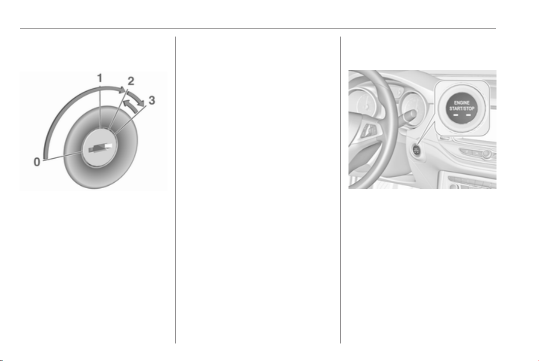
Starting the engine
Ignition switch
● Turn key to position 2.
● Move the steering wheel slightly
to release the steering wheel
lock.
● Manual transmission: operate
clutch and brake pedal.
Manual transmission automated:
operate brake pedal.
Automatic transmission: operate
brake pedal and move selector
lever to P or N.
● Do not operate accelerator pedal.
● Diesel engines: wait until control
indicator ! for preheating
extinguishes.
● Turn key to position 3 and
release after engine has been
started.
Starting the engine 3 160.
To turn the key back from position 2
to 1 or 0, first push the key all the way
in towards the steering column.
Power button
● Press Engine Start/Stop for a few
seconds until green LED
illuminates.
● Move the steering wheel slightly
to release the steering wheel
lock.
● Manual transmission: operate
clutch and brake pedal.
Manual transmission automated:
operate brake pedal.
Automatic transmission: operate
brake pedal and move selector
lever to P or N.
● Do not operate accelerator pedal.
● Diesel engines: wait until control
indicator ! for preheating
extinguishes.
● Press Engine Start/Stop and
release.
Starting the engine 3 160.
Page 21
In brief 19
Stop-start system
If the vehicle is at a low speed or at a
standstill and certain conditions are
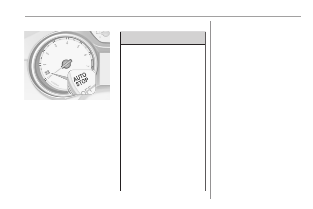
fulfilled, an Autostop is activated.
An Autostop is indicated by the
needle at the AUTOSTOP position in
the tachometer.
A restart is indicated by the needle at
the idle speed position in the
tachometer.
Stop-start system 3 162.
Parking
9 Warning
● Do not park the vehicle on an
easily ignitable surface. The
high temperature of the
exhaust system could ignite the
surface.
● Always apply the parking
brake. Activate the manual
parking brake without pressing
the release button. Apply as
firmly as possible on a downhill
slope or uphill slope. Depress
brake pedal at the same time to
reduce operating force.
For vehicles with electric
parking brake, pull switch m for
a minimum of one second until
control indicator m illuminates
constantly and electric parking
brake is applied 3 110.
● Switch off the engine.
● If the vehicle is on a level
surface or uphill slope, engage
first gear or set the selector
lever to position P before
removing the ignition key or
switching off ignition on
vehicles with power button. On
an uphill slope, turn the front
wheels away from the kerb.
If the vehicle is on a downhill
slope, engage reverse gear or
set the selector lever to position
P before removing the ignition
key or switching off ignition on
vehicles with power button.
Turn the front wheels towards
the kerb.
● Close the windows and the
sunroof.
● Remove the ignition key from
the ignition switch or switch off
ignition on vehicles with power
button. Turn the steering wheel
until the steering wheel lock is
felt to engage.
For vehicles with automatic
transmission, the key can only
be removed when the selector
lever is in position P.
Page 22

20 In brief
For vehicles with manual
transmission automated, the
key can only be removed from
the ignition switch when the
parking brake is applied.
●
Lock the vehicle with e on the
radio remote control.
Activate the anti-theft alarm
system 3 37.
● The engine cooling fans may run
after the engine has been
switched off 3 231.
Caution
After running at high engine
speeds or with high engine loads,
operate the engine briefly at a low
load or run in neutral for
approx. 30 seconds before
switching off, in order to protect
the turbocharger.
Keys, locks 3 21, Laying-up the
vehicle for a long period of time
3 230.
Page 23

Keys, doors and windows 21
Keys, doors and windows
Keys, locks ................................... 21
Keys .......................................... 21
Radio remote control ................. 22
Electronic key system ................ 23
Memorised settings ................... 25
Central locking system .............. 25
Automatic locking ...................... 30
Child locks ................................. 31
Doors ........................................... 31
Load compartment .................... 31
Vehicle security ............................ 37
Anti-theft locking system ...........37
Anti-theft alarm system .............. 37
Immobiliser ................................ 39
Exterior mirrors ............................ 40
Convex shape ........................... 40
Electric adjustment .................... 40
Folding mirrors .......................... 40
Heated mirrors ........................... 41
Interior mirrors ............................. 41
Manual anti-dazzle .................... 41
Automatic anti-dazzle ................ 42
Windows ...................................... 42
Windscreen ............................... 42
Manual windows ........................ 42
Power windows ......................... 42
Heated rear window .................. 44
Sun visors .................................. 44
Roof ............................................. 45
Sunroof ...................................... 45
Keys, locks
Keys
Caution
Do not attach heavy or bulky items
to the ignition key.
Replacement keys
The key number is specified on a
detachable tag.
The key number must be quoted
when ordering replacement keys as it
is a component of the immobiliser
system.
Locks 3 275, Central locking 3 25,
Starting the engine 3 160.
Radio remote control 3 22.
Electronic key 3 23.
The code number of the adapter for
the locking wheel nuts is specified on
a card. It must be quoted when
ordering a replacement adapter.
Wheel changing 3 266.
Page 24
22 Keys, doors and windows
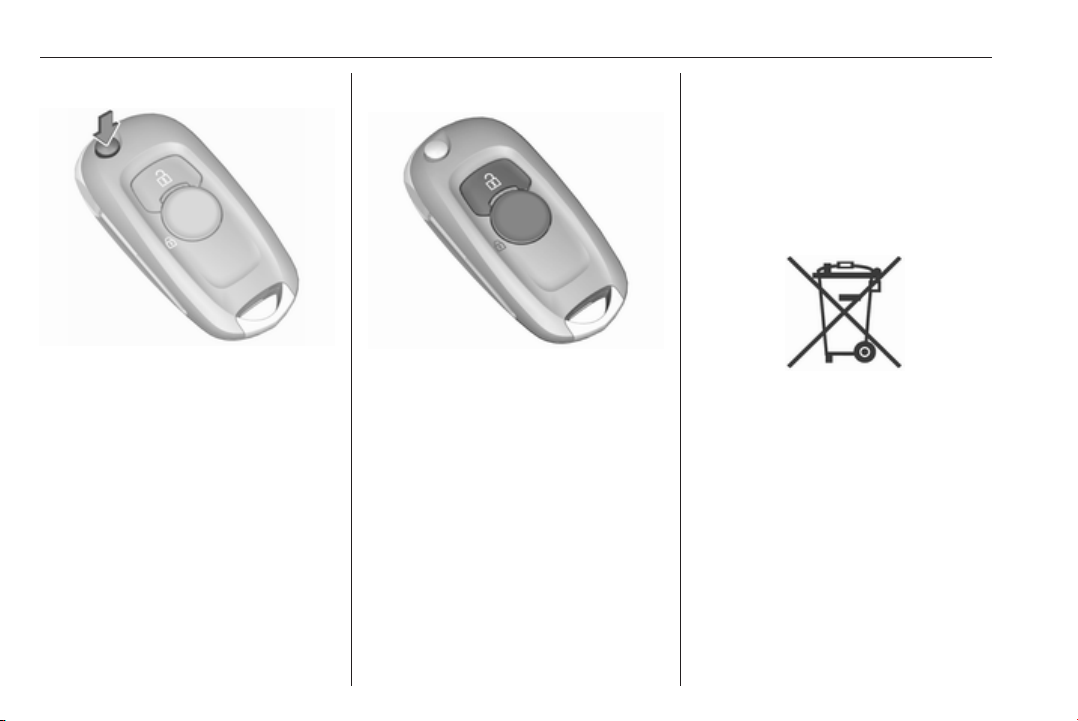
Key with foldaway key section
Press button to extend. To fold the
key, first press the button.
Radio remote control
Enables operation of the following
functions via the use of the remote
control buttons:
● central locking system 3 25
● anti-theft locking system 3 37
● anti-theft alarm system 3 37
● power windows 3 42
● sunroof 3 45
The remote control has a range of up
to 100 metres, but may also be much
less due to external influences. The
hazard warning flashers confirm
operation.
Handle with care, protect from
moisture and high temperatures and
avoid unnecessary operation.
Replacing battery in radio remote control
Replace the battery as soon as the
range reduces.
Batteries do not belong in household
waste. They must be disposed of at
an appropriate recycling collection
point.
Page 25

Keys, doors and windows 23
1. Insert flat screwdriver into the slot
and separate the back cover from
the remote control by slightly
turning the screwdriver.
2. Remove and replace battery. Use
CR 2032 or equivalent battery.
Pay attention to the installation
position.
3. Insert the back cover in the area
of the key blade, fold down and
close.
Fault
If the central locking system cannot
be operated with the radio remote
control, the cause may be one of the
following:
● Fault in radio remote control.
● The range is exceeded.
● The battery voltage is too low.
● Frequent, repeated operation of
the radio remote control while not
in range, which will require resynchronisation.
● Overload of the central locking
system by operating at frequent
intervals, the power supply is
interrupted for a short time.
● Interference from higher-power
radio waves from other sources.
Manual unlocking 3 25.
Electronic key system
Enables a keyless operation of the
following functions:
● central locking system 3 25
● power tailgate 3 31
● ignition switching on and starting
the engine 3 160
The electronic key simply needs to be
on the driver's person.
Additionally, the electronic key
includes the functionality of the radio
remote control 3 22.
Handle with care, protect from
moisture and high temperatures and
avoid unnecessary operation.
Page 26

24 Keys, doors and windows
Note
Do not put the electronic key into the
load compartment or in front of the
Info-Display.
Replacing battery in electronic key
Replace the battery as soon as the
system no longer operates properly
or the range is reduced. The need for
battery replacement is indicated by a
message in the Driver Information
Centre 3 123.
Batteries do not belong in household
waste. They must be disposed of at
an appropriate recycling collection
point.
To replace:
1. Press button at the back of the
electronic key unit and extract the
key blade from the housing.
2. Insert the key blade again for
approx. 6 mm and turn the key to
open the housing. Further
insertion of the key blade can
damage the housing.
3. Remove and replace battery. Use
CR 2032 or equivalent battery.
Pay attention to the installation
position.
4. Close the housing and insert key
blade.
Electronic key synchronisation
The electronic key synchronises itself
automatically during every starting
procedure.
Fault
If the central locking cannot be
operated or the engine cannot be
started, the cause may be one of the
following:
● Fault in electronic key.
● Electronic key is out of reception
range.
● The battery voltage is too low.
Page 27

Keys, doors and windows 25
● Overload of the central locking
system by operating at frequent
intervals, the power supply is
interrupted for a short time.
● Interference from higher-power
radio waves from other sources.
To rectify the cause of the fault,
change the position of the electronic
key.
Manual unlocking 3 25.
Memorised settings
Whenever the ignition is switched off,
some functions of the following
settings may be automatically
memorised by the remote control unit
or the electronic key:
● automatic climate control
● lighting
● Infotainment system
● central locking system
● comfort settings
The saved settings are automatically
used the next time the ignition is
switched on with the memorised key
of the remote control unit 3 157 or
electronic key 3 23.
A precondition is that Personalisation
by Driver is activated in the personal
settings of the Info-Display. This must
be set for each remote control unit or
electronic key which is used. The
status change is available only after
locking and unlocking the vehicle.
The assigned memory position of the
power seat is automatically recalled
when switching on ignition and Auto
Memory Recall is activated in the
Info-Display for the memorised
remote control or electronic key.
Power seat 3 51.
Vehicle personalisation 3 125.
Central locking system
Unlocks and locks doors, load
compartment and fuel filler flap.
A pull on an interior door handle
unlocks the respective door. Pulling
the handle once more opens the door.
Note
In the event of an accident in which
airbags or belt pretensioners are
deployed, the vehicle is
automatically unlocked.
Note
A short time after unlocking with the
remote control the doors are locked
automatically if no door has been
opened. A precondition is that the
setting is activated in the vehicle
personalisation 3 125.
Remote control operation
Unlocking
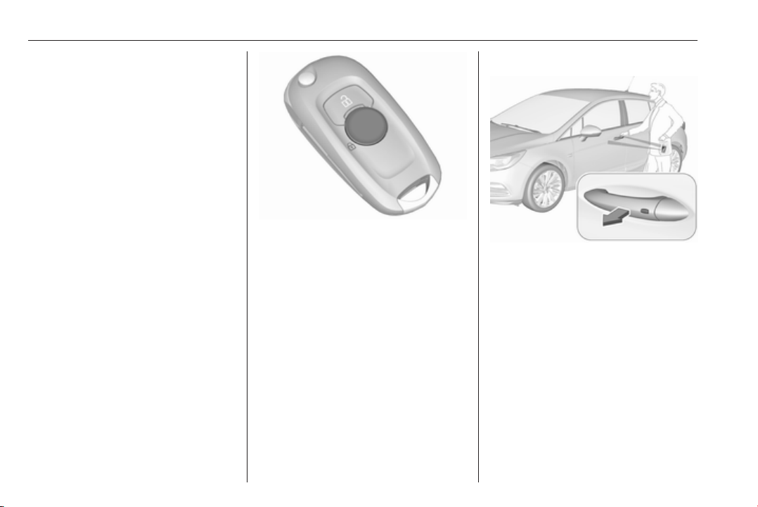
Press c.
Page 28
26 Keys, doors and windows
Unlocking mode can be set in the
vehicle personalisation menu in the
Info Display. Two settings are
selectable:
● All doors, load compartment and
fuel filler flap will be unlocked by
pressing c once.
● Only the driver's door and fuel
filler flap will be unlocked by
pressing c once. To unlock all
doors and load compartment,
press c twice.
Select the relevant setting in Settings,
I Vehicle in the Info-Display.
Info-Display 3 121.
Vehicle personalisation 3 125.
The setting can be saved for the
remote control being used.
Memorised settings 3 25.
Unlocking and opening the tailgate
3 31.
Locking
Close doors, load compartment and
fuel filler flap.
Press e.
If the driver's door is not closed
properly, the central locking system
will not work.
Confirmation
Operation of the central locking
system is confirmed by the hazard
warning flashers. A precondition is
that the setting is activated in the
vehicle personalisation 3 125.
Electronic key system operation
The electronic key must be outside
the vehicle, within a range of approx.
one metre of the relevant door side.
Page 29
Keys, doors and windows 27
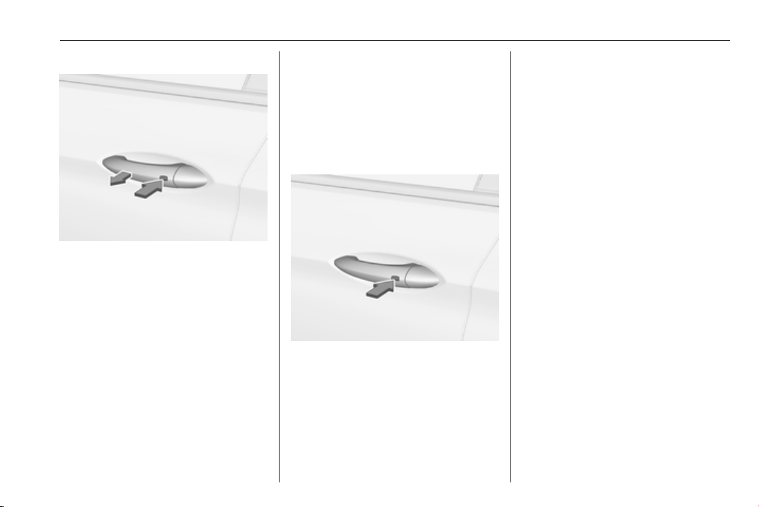
Unlocking
Press the button on a front door
handle and pull the handle.
Unlocking mode can be set in the
vehicle personalisation menu in the
Info Display. Two settings are
selectable:
● All doors, load compartment and
fuel filler flap will be unlocked by
pressing the button on any
exterior handle once.
● Only the driver's door and fuel
filler flap will be unlocked by
pressing the button on the
driver's door exterior handle
once. To unlock front doors and
load compartment, press button
twice.
The setting can be changed in the
menu Settings in the Info Display.
Vehicle personalisation 3 125.
Locking
Press the button on a front door
handle.
All doors, load compartment and fuel
filler flap will be locked.
The system locks if any of the
following occurs:
● It has been more than
five seconds since unlocking.
● The button on an exterior handle
has been pressed twice within
3 s to unlock the vehicle.
● Any door has been opened and
all doors are now closed.
If the driver's door is not closed
properly, the electronic key remains in
the vehicle or the ignition is not off,
locking will not be permitted.
If there have been two or more
electronic keys in the vehicle and the
ignition was on once, the doors will be
locked even if just one electronic key
is taken out of the vehicle.
Unlocking and opening the tailgate
The tailgate can be unlocked and
opened handsfree via moving the foot
below the rear bumper or by pushing
the touchpad switch under the brand
emblem when the electronic key is in
range. The doors remain locked.
Load compartment 3 31.
Page 30
28 Keys, doors and windows
Operation with buttons on the electronic key
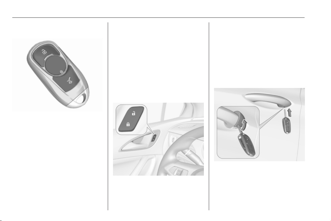
The central locking system can also
be operated with the buttons on the
electronic key.
Press c to unlock.
Press e to lock.
Press X twice to unlock and open
only the power tailgate. To prevent
unintended opening of the tailgate,
X must be pressed longer than
during locking or unlocking.
Remote control operation 3 25.
Passive locking
Automatic locking 3 30.
Confirmation
Operation of central locking system is
confirmed by the hazard warning
flashers. A precondition is that the
setting is activated in the vehicle
personalisation 3 125.
Central locking buttons
Locks or unlocks all doors, the load
compartment and fuel filler flap from
the passenger compartment via a
switch in the driver's door panel.
Press e to lock.
Press c to unlock.
Operation with the key in case of a central locking system fault
In case of a fault, e.g. vehicle battery
or remote control/electronic key
battery is discharged, the driver's
door can be locked or unlocked with
the mechanical key.
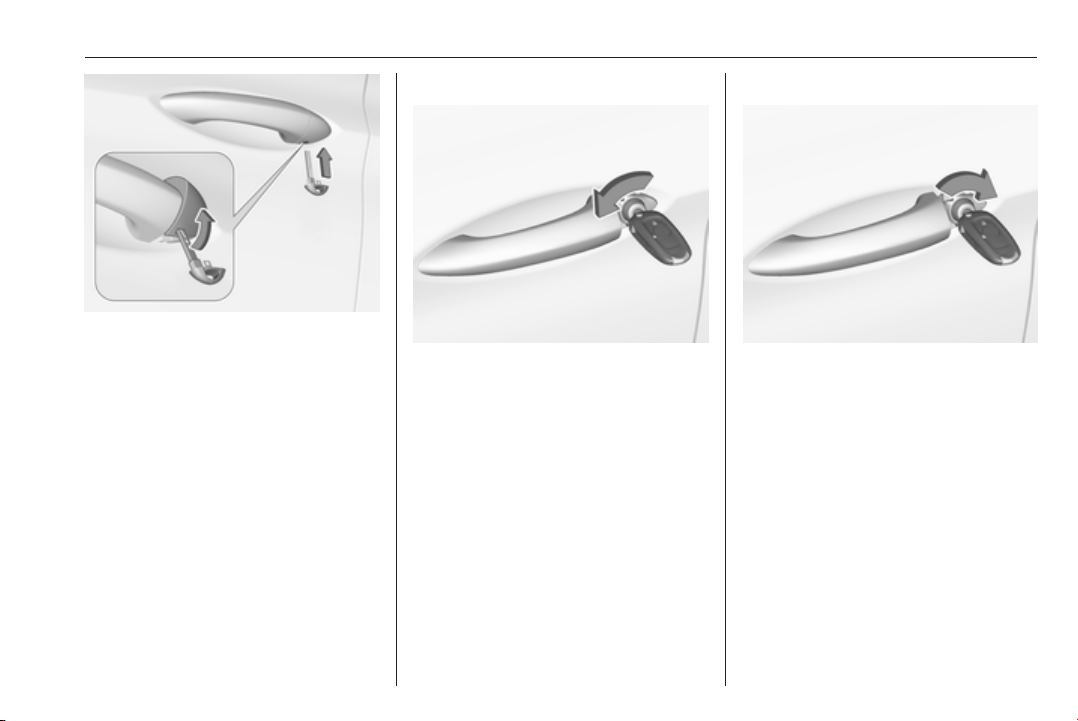
The lock cylinder in the driver's door
is covered by a cap.
Remote control: to remove the cap,
insert the key into the recess at the
bottom of the cap and swivel the key
upward.
Keys 3 21.
Page 31
Keys, doors and windows 29
Electronic key: to remove the cap,
press button at the back and extract
the key blade from the housing. Insert
the key into the recess at the bottom
of the cap and swivel the key upward.
Electronic key system 3 23.
Manual unlocking
Manually unlock the driver's door by
inserting and turning the key in the
lock cylinder.
The other doors can be opened by
pulling the interior handle twice or by
pressing c in the driver's door panel.
The load compartment and fuel filler
flap will possibly not be unlocked.
By switching on the ignition, the antitheft locking system is deactivated.
Manual locking
Push inside locking knob of all doors
except driver's door or press e in the
driver's door panel. Then close the
driver's door and lock it from the
outside by turning the key in the lock
cylinder. The fuel filler flap and
tailgate are possibly not locked.
Page 32
30 Keys, doors and windows
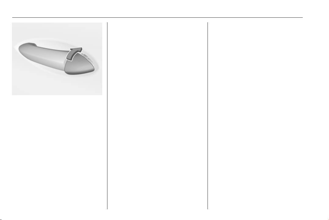
After locking, cover the lock cylinder
with the cap: insert the cap with the
lower side in the recesses, swivel and
push the cap until it engages at the
upper side.
Automatic locking
Automatic locking after driving off
This security feature can be
configured to automatically lock all
doors, load compartment and fuel
filler flap after driving off and
exceeding a certain speed.
When at a standstill after driving, the
vehicle will be unlocked automatically
as soon as the key is removed from
the ignition switch, or with electronic
key system when the ignition is
switched off.
Activation or deactivation of
automatic locking can be set in the
menu Settings, I Vehicle in the InfoDisplay.
Info-Display 3 121.
Vehicle personalisation 3 125.
The setting can be saved for the
remote control or electronic key being
used 3 25.
Automatic relock after unlocking
This feature can be configured to
automatically lock all doors, load
compartment and fuel filler flap a
short time after unlocking with the
remote control or electronic key,
provided no door has been opened.
Activation or deactivation of
automatic relock can be set in the
menu Settings, I Vehicle in the InfoDisplay.
Info-Display 3 121.
Vehicle personalisation 3 125.
The setting can be saved for the
remote control or electronic key being
used 3 25.
Passive locking
On vehicles with electronic key
system, this feature locks the vehicle
automatically after several seconds if
an electronic key has been
recognised previously inside the
vehicle, all doors have then been
closed and the electronic key does
not remain within the vehicle.
If the electronic key remains in the
vehicle or the ignition is not off,
passive locking will not be permitted.
If there have been two or more
electronic keys in the vehicle and the
ignition was on once, the feature
locks the vehicle if just one electronic
key is taken out of the vehicle.
To prevent passive locking of the
vehicle e.g. when refuelling or if
passengers remain in the vehicle, the
system must be disabled.
Page 33
Keys, doors and windows 31
To disable the system, press the
central locking button c for a few
seconds while one door is open. An
acoustic signal sounds three times to
confirm deactivation. The function
remains disabled until the central
locking button e is pressed or the
ignition is switched on.
Activation or deactivation of passive
locking can be set in the menu
Settings, I Vehicle in the Info-Display.
Info-Display 3 121.
Vehicle personalisation 3 125.
The setting can be saved for the
electronic key being used 3 25.
Child locks
9 Warning
Use the child locks whenever
children are occupying the rear
seats.
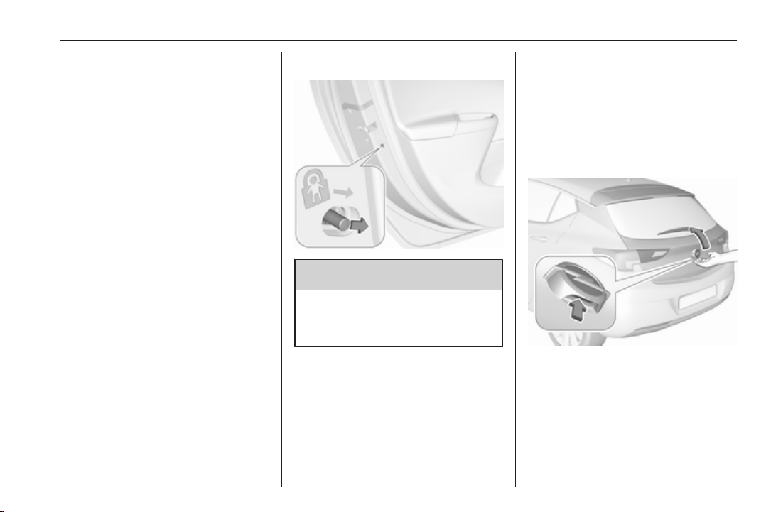
Move the pin in the rear door to the
front. The door cannot be opened
from the inside.
To deactivate, move the pin to the
rear position.
Doors
Load compartment
Tailgate
Opening
5-door Hatchback
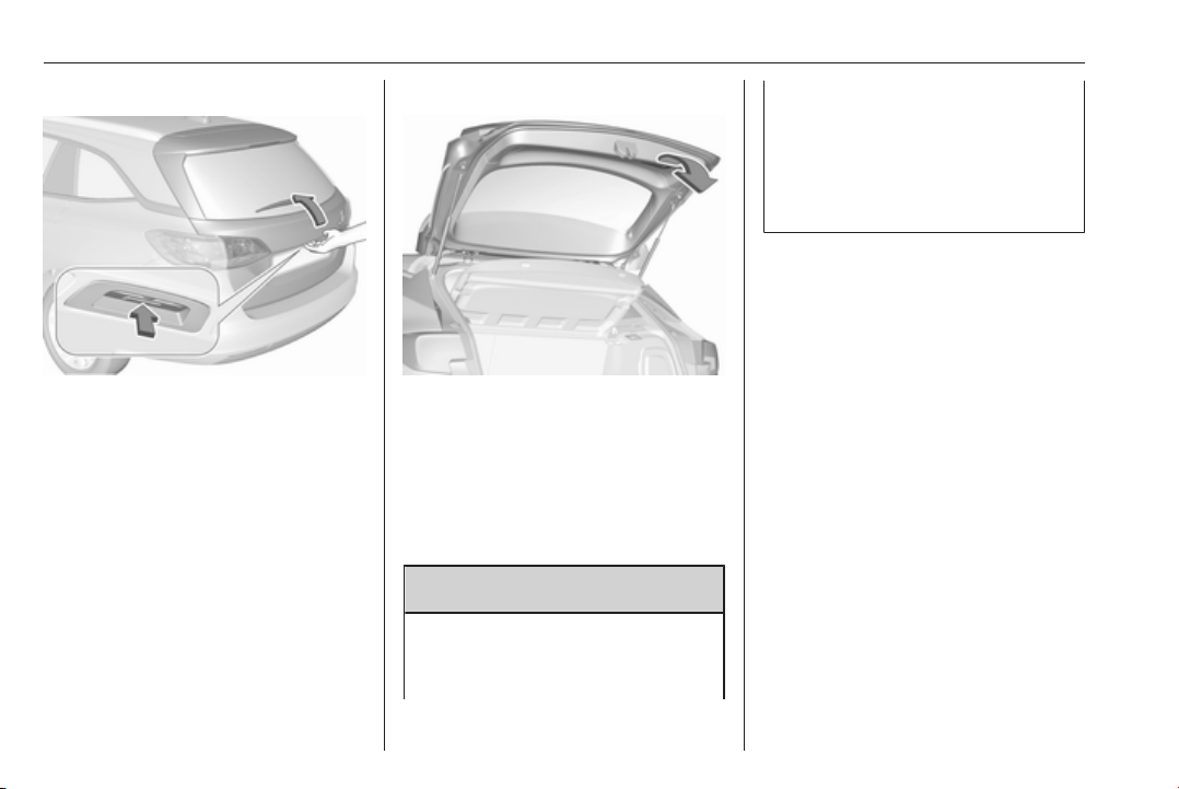
After unlocking, push the touchpad
switch under the brand emblem and
open the tailgate.
Page 34
32 Keys, doors and windows
Sports Tourer
After unlocking, push the touchpad
switch under the tailgate moulding
and open the tailgate manually.
Central locking system 3 25.
Closing
Use one of the interior handles.
Do not push the touchpad switch
whilst closing as this will unlock the
tailgate again.
Central locking system 3 25.
Power tailgate
9 Warning
Take care when operating the
power tailgate. Risk of injury,
particularly to children.
Keep a close watch on the
movable tailgate when operating.
Ensure that nothing becomes
trapped during operating and no
one is standing within the moving
area.
The power tailgate can be operated
by:
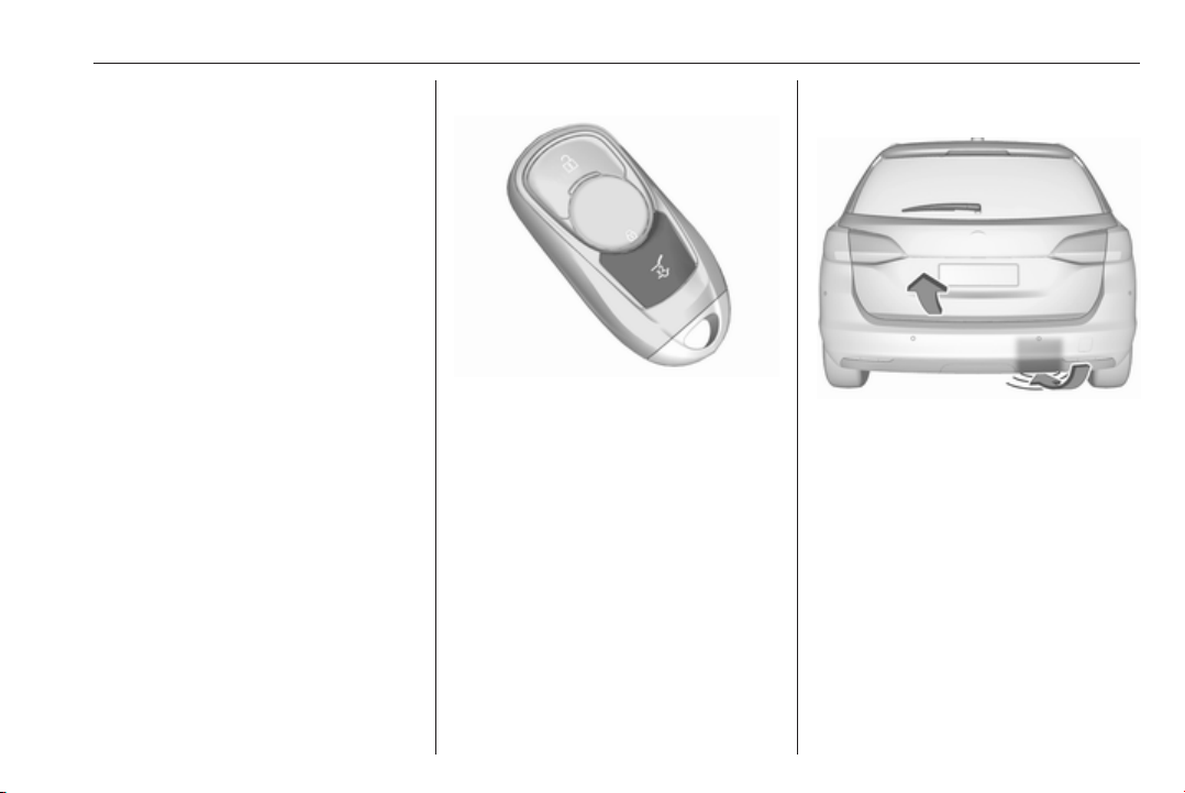
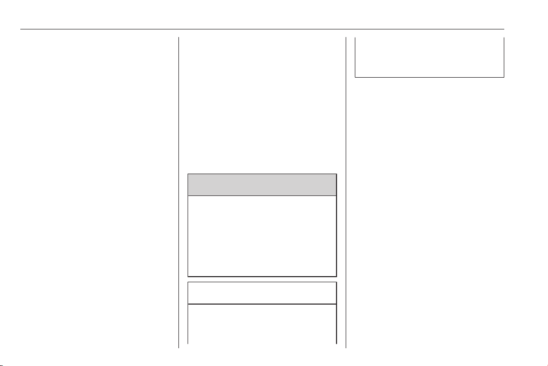
● Pressing X twice on the
electronic key. To prevent
unintended opening of the
tailgate, X must be pressed
longer than during locking or
unlocking.
● Handsfree operation with motion
sensor below the rear bumper.
● The touchpad switch under the
exterior tailgate moulding and
C in the open tailgate.
● The switch C on the inside of
the driver's door.
On vehicles with automatic
transmission, the tailgate can only be
operated when the vehicle is
stationary and with selector lever in P.
Page 35
Keys, doors and windows 33
The turn signal lights flash and a
chime sounds when the power
tailgate is operating.
Note
Operating the power tailgate does
not operate the central locking
system. To open the tailgate with the
button on the electronic key, or with
the touchpad switch under the
tailgate moulding or via handsfree
operation, it is not necessary to
unlock the vehicle. A precondition is
that the electronic key is outside the
vehicle, within a range of approx.
one metre of the tailgate.
Do not leave the electronic key in the
load compartment.
Lock the vehicle after closing if it was
unlocked previously.
Central locking system 3 25.
Operation with the electronic key
Press X twice to open or close the
tailgate. To prevent unintended
opening of the tailgate, X must be
pressed longer than during locking or
unlocking.
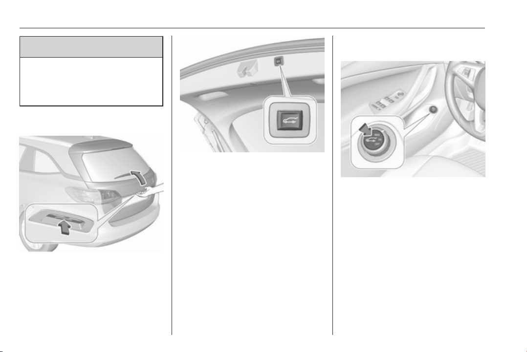
Handsfree operation with motion sensor below the rear bumper
To open or close the tailgate, move
the foot below the rear bumper back
and forth in the area shown in the
illustration. If equipped with parking
assist, the area is recognisable below
the sensor shown. Do not hold the
foot longer or move too slow below
the bumper. The electronic key must
be outside the vehicle, within a range
of approx. one metre of the tailgate.
Page 36
34 Keys, doors and windows
9 Danger
Do not touch any vehicle parts
below the vehicle during
handsfree operation. There is a
risk of injury from hot engine parts.
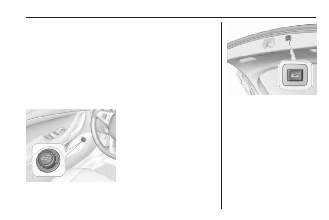
Operation with the touchpad switch under the exterior tailgate moulding
To open the tailgate, press the
touchpad switch under the tailgate
moulding until the tailgate starts to
move. If the vehicle is locked, the
electronic key must be outside the
vehicle, within a range of approx.
one metre of the tailgate.
To close, press C in the open
tailgate until the tailgate starts to
move.
Operation with the switch on the inside of the driver's door
Press C on the inside of the driver's
door until the tailgate starts to open or
close.
Stop or change direction of movement
To stop movement of the tailgate
immediately:
● press X once on the electronic
key, or
● press the touchpad switch under
the exterior tailgate moulding, or
Page 37
Keys, doors and windows 35
● press C on the open tailgate,
or
● press C on the inside of the
driver's door.
Pressing one of the switches again
will reverse the direction of
movement.
Operation modes
The power tailgate has three modes
of operation, which are controlled by
the switch C in the driver's door. To
change the mode, turn the switch:
● Normal mode MAX: Power
tailgate opens to full height.
● Intermediate mode 3/4: Power
tailgate opens to a reduced
height that can be adjusted.
● Mode Off: Tailgate can only be
operated manually.
Adjust reduced opening height in intermediate mode
1. Turn operation mode switch to
3/4.
2. Open power tailgate with any
operation switch.
3. Stop movement at the desired
height by pressing any operation
switch. If required, manually move
the stopped tailgate to the desired
position.
4. Press and hold the button C on
the inside of the open tailgate for
three seconds.
Note
Adjusting opening height should be
programmed at ground level.
A chime sound indicates the new
setting and the turn signal lights will
flash. The reduced height can only set
at an opening angle of above 30°.
When turning the adjuster wheel in
the driver's door to intermediate mode
3/4, the power tailgate will stop
opening at the newly set position.
Page 38
36 Keys, doors and windows
The tailgate can only be held open if
a minimum height is exceeded
(minimum opening angle from 30°).
The opening height cannot be
programmed below that height.
Safety function
If the power tailgate encounters an
obstacle during opening or closing,
the direction of movement will
automatically be reversed slightly.
Multiple obstacles in one power cycle
will deactivate the function. In this
case, close or open the tailgate
manually.
The power tailgate has pinch sensors
on the side edges. If the sensors
detect obstacles between tailgate and
chassis, the tailgate will open, until it
is activated again or closed manually.
The safety function is indicated by a
warning chime.
Remove all obstacles before
resuming normal power operation.
If the vehicle is equipped with factoryfitted towing equipment and a trailer
is electrically connected, the power
tailgate can only be opened with the
touchpad switch or closed with G in
the open tailgate. Ensure that there
are no obstacles in the moving area.
Overload
If the power tailgate is repeatedly
operated at short intervals, the
function is disabled for some time.
Move tailgate manually into end
position to reset the system.
General hints for operating tailgate
9 Danger
Do not drive with the tailgate open
or ajar, e.g. when transporting
bulky objects, since toxic exhaust
gases, which cannot be seen or
smelled, could enter the vehicle.
This can cause unconsciousness
and even death.
Caution
Before opening the tailgate, check
overhead obstructions, e.g. a
garage door, to avoid damage to
the tailgate. Always check the
moving area above and behind the
tailgate.
Note
The installation of certain heavy
accessories onto the tailgate may
affect its ability to remain open.
Note
The operation of the power tailgate
is disabled under low vehicle battery
conditions. In this case, the tailgate
may not even by manually operable.
Note
With the power tailgate disabled and
all doors unlocked, the tailgate can
only be operated manually. In this
event, manually closing the tailgate
requires significantly greater force.
Note
At low outside temperatures the
tailgate may not open fully by itself.
In this event, lift the tailgate manually
to its normal end position.
Page 39
Keys, doors and windows 37
Vehicle security
Anti-theft locking system
9 Warning
Do not use the system if there are
people in the vehicle! The doors
cannot be unlocked from the
inside.
The system deadlocks all the doors.
All doors must be closed otherwise
the system cannot be activated.
Unlocking the vehicle disables the
mechanical anti-theft locking system.
This is not possible with the central
locking button.
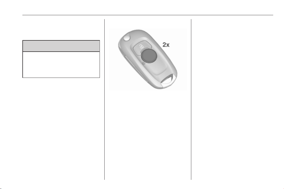
Activating
Press e on the radio remote control
twice within five seconds.
Anti-theft alarm system
The anti-theft alarm system is
combined with the anti-theft locking
system.
It monitors:
● doors, tailgate, bonnet
● passenger compartment
including adjoining load
compartment
● vehicle inclination, e.g. if it is
raised
● ignition
Activation
All doors must be closed and the
electronic key of the electronic key
system must not remain in the
vehicle. Otherwise the system cannot
be activated.
● Radio remote control: selfactivated 30 seconds after
locking the vehicle by pressing e
once.
● Electronic key system: selfactivated 30 seconds after
locking the vehicle by pressing
the button on any exterior door
handle.
Page 40
38 Keys, doors and windows
● Radio remote control or
electronic key: directly by
pressing e twice within
five seconds.
● Electronic key system with
passive locking enabled: briefly
activated after passive locking
occurs.
Note
Changes to the vehicle interior such
as the use of seat covers, and open
windows or sunroof, could impair the
function of passenger compartment
monitoring.
Activation without monitoring of passenger compartment and vehicle inclination
Switch off the monitoring of
passenger compartment and vehicle
inclination when animals are being
left in the vehicle, because of high
volume ultrasonic signals or
movements triggering the alarm. Also
switch off when the vehicle is on a
ferry or train.
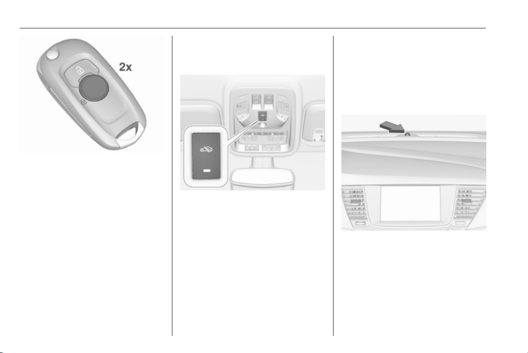
1. Close tailgate, bonnet, windows
and sunroof.
2. Press o. LED in the button o
illuminates for a maximum of
ten minutes.
3. Close doors.
4. Activate the anti-theft alarm
system.
Status message is displayed in the
Driver Information Centre.
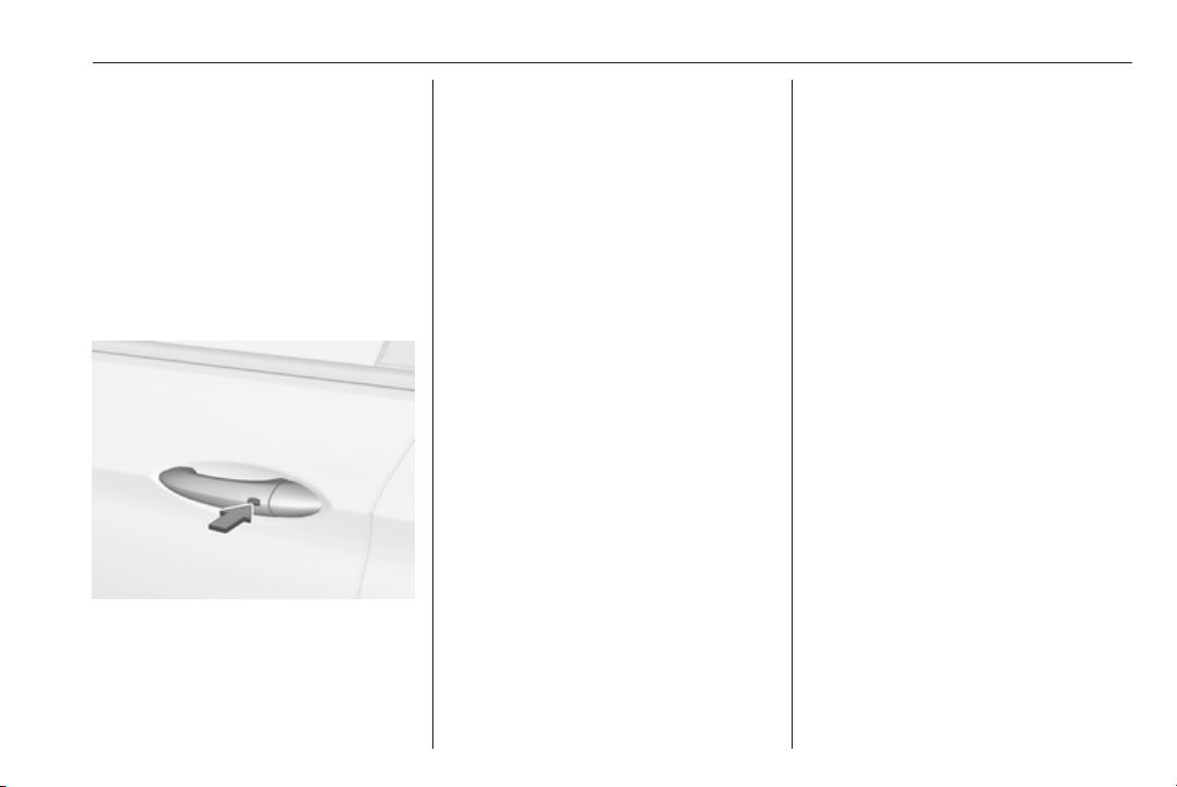
Status LED
Status LED is integrated in the sensor
on top of the instrument panel.
Status during the first 30 seconds of
anti-theft alarm system activation:
LED illuminates : test, arming delay
LED flashes
quickly
: doors, tailgate or
bonnet not
completely closed,
or system fault
Page 41
Keys, doors and windows 39
Status after system is armed:
LED flashes
slowly
Seek the assistance of a workshop in
the event of faults.
: system is armed
Deactivation
Radio remote control: Unlocking the
vehicle by pressing c deactivates the
anti-theft alarm system.
Electronic key system: Unlocking the
vehicle by pressing the button on any
exterior door handle deactivates the
anti-theft alarm system.
The electronic key must be outside
the vehicle, within a range of approx.
one metre of the relevant door side.
The system is not deactivated by
unlocking the driver's door with the
key or with the central locking button
in the passenger compartment.
Alarm
When triggered, the alarm horn
sounds and the hazard warning lights
flash simultaneously. The number
and duration of alarm signals are
stipulated by legislation.
The anti-theft alarm system can be
deactivated by pressing c, by
pressing the switch on the door
handle with electronic key system or
switching on the ignition.
A triggered alarm, which has not been
interrupted by the driver, will be
indicated by the hazard warning
lights. They will flash quickly three
times the next time the vehicle is
unlocked with the radio remote
control. Additionally a warning
message is displayed in the Driver
Information Centre after switching on
the ignition.
Vehicle messages 3 123.
If the vehicle's battery is to be
disconnected (e.g. for maintenance
work), the alarm siren must be
deactivated as follows: switch the
ignition on then off, then disconnect
the vehicle's battery within
15 seconds.
Immobiliser
The system is part of the ignition
switch and checks whether the
vehicle is allowed to be started with
the key being used.
The immobiliser is activated
automatically after the key has been
removed from the ignition switch.
If the control indicator d flashes when
the ignition is on, there is a fault in the
system; the engine cannot be started.
Switch off the ignition and repeat the
start attempt.
If the control indicator d continues
flashing, attempt to start the engine
using the spare key and seek the
assistance of a workshop.
Page 42
40 Keys, doors and windows
Note
Radio Frequency Identification
(RFID) tags may cause interference
with the key. Do not have it placed
near the key when starting the
vehicle.
Note
The immobiliser does not lock the
doors. You should always lock the
vehicle after leaving it and switch on
the anti-theft alarm system 3 25,
3 37.
Control indicator d 3 113.
Exterior mirrors
Convex shape
The shape of the mirror makes
objects appear smaller, which will
affect the ability to estimate
distances.
Side blind spot alert 3 209.
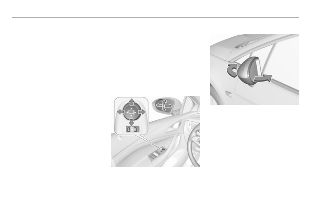
Electric adjustment
Select the relevant exterior mirror by
switching the control to left (L) or right
(R). Then swivel the control to adjust
the mirror.
In position o no mirror is selected.
Folding mirrors
For pedestrian safety, the exterior
mirrors will swing out of their normal
mounting position if they are struck
with sufficient force. Reposition the
mirror by applying slight pressure to
the mirror housing.
Page 43
Keys, doors and windows 41
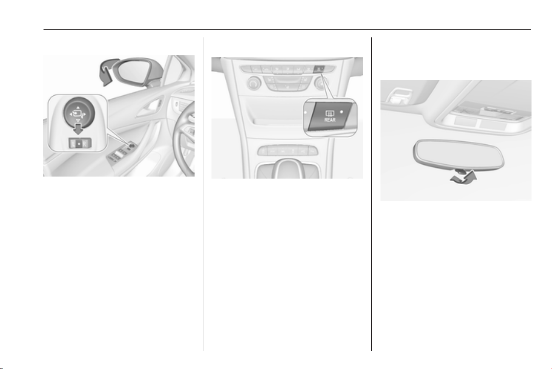
Electric folding
Switch control to o, then push the
control c down. Both exterior mirrors
will fold.
Push the control down again - both
exterior mirrors return to their original
position.
If an electrically folded mirror is
manually extended, pressing down
the control will only electrically extend
the other mirror.
Heated mirrors
Operated by pressing Ü.
Heating works with the engine
running and is switched off
automatically after a short time.
Interior mirrors
Manual anti-dazzle
To reduce dazzle, adjust the lever on
the underside of the mirror housing.
Page 44
42 Keys, doors and windows
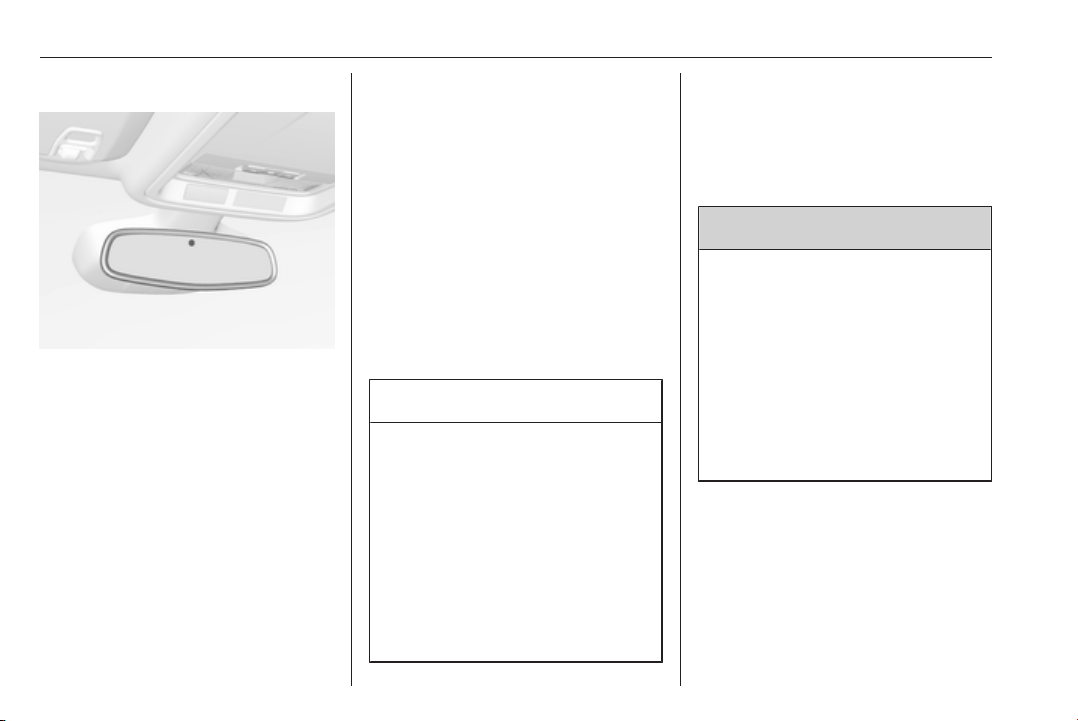
Automatic anti-dazzle
Dazzle from following vehicles is
automatically reduced, when driving
in the dark.
Windows
Windscreen
Windscreen stickers
Do not attach stickers such as toll
road stickers or similar on the
windscreen in the area of the interior
mirror. Otherwise the detection zone
of the sensor and the view area of the
camera in the mirror housing could be
restricted.
Windscreen replacement
Caution
If the vehicle has a front-looking
camera sensor for the driver
assistance systems, it is very
important that any windscreen
replacement is performed
accurately according to Opel
specifications. Otherwise, these
systems may not work properly
and there is a risk of unexpected
behaviour and/or messages from
these systems.
Manual windows
The door windows can be opened or
closed with the window cranks.
Power windows
9 Warning
Take care when operating the
power windows. Risk of injury,
particularly to children.
If there are children on the rear
seats, switch on the child safety
system for the power windows.
Keep a close watch on the
windows when closing them.
Ensure that nothing becomes
trapped in them as they move.
Switch on ignition to operate power
windows. Retained power off 3 160.
Page 45
Keys, doors and windows 43
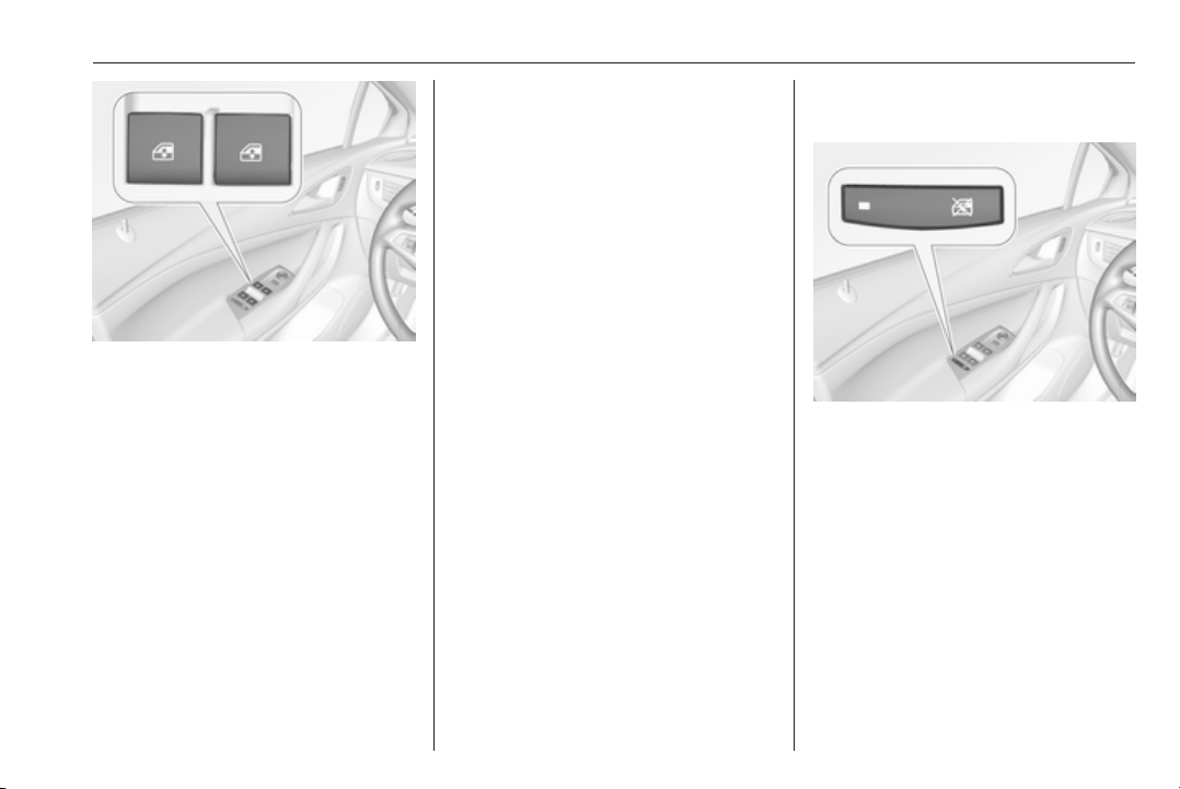
Operate the switch for the respective
window by pushing to open or pulling
to close.
Pushing or pulling gently to the first
detent: window moves up or down as
long as the switch is operated.
Pushing or pulling firmly to the second
detent then releasing: window moves
up or down automatically with safety
function enabled. To stop movement,
operate the switch once more in the
same direction.
Safety function
If the window glass encounters
resistance above the middle of the
window during automatic closing, it is
immediately stopped and opened
again.
Override safety function
In the event of closing difficulties due
to frost or the like, switch on the
ignition, then pull the switch to the first
detent and hold. The window moves
up without safety function enabled.
To stop movement, release the
switch.
Child safety system for rear windows
Press z to deactivate rear door
power windows; the LED illuminates.
To activate, press z again.
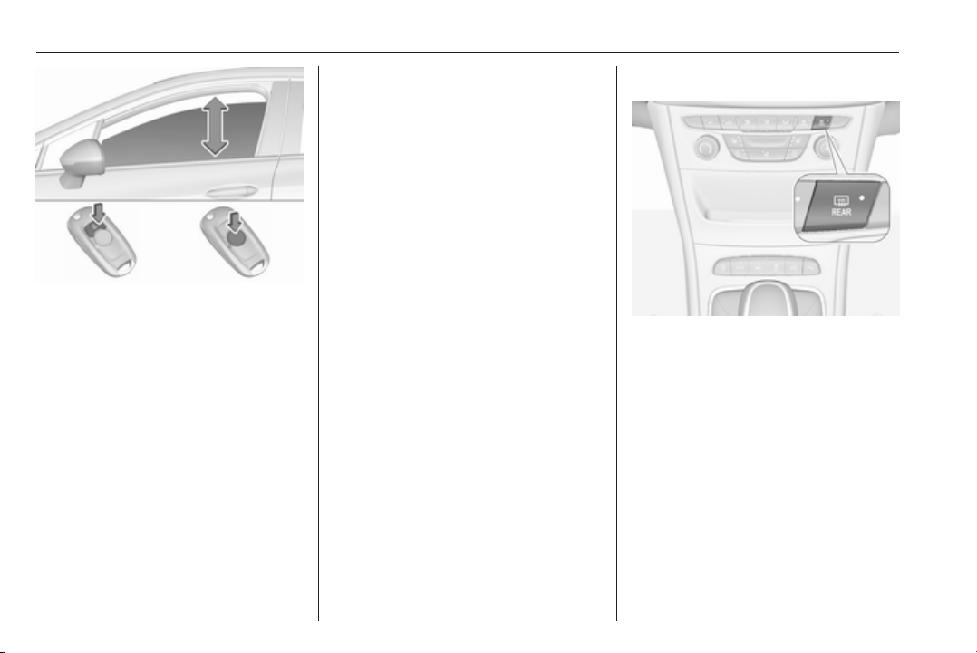
Operating windows from outside
The windows can be operated
remotely from outside the vehicle.
Page 46
44 Keys, doors and windows
Press and hold c to open windows.
Press and hold e to close windows.
Release button to stop window
movement.
If the windows are fully opened or
closed, the hazard warning lights will
flash twice.
Overload
If the windows are repeatedly
operated within short intervals, the
window operation is disabled for
some time.
Initialising the power windows
If the windows cannot be closed
automatically (e.g. after
disconnecting the vehicle battery), a
warning message is displayed in the
Driver Information Centre.
Vehicle messages 3 123.
Activate the window electronics as
follows:
1. Close doors.
2. Switch on ignition.
3. Pull switch until the window is
closed and keep pulling for
additional two seconds.
4. Push switch until the window is
completely open and keep
pushing for additional
two seconds.
5. Repeat for each window.
Heated rear window
Operated by pressing Ü.
Heating works with the engine
running and is switched off
automatically after a short time.
Sun visors
The sun visors can be folded down or
swivelled to the side to prevent
dazzling.
The covers of the mirrors should be
closed when driving.
A ticket holder is located on the
backside of the sun visor.
Page 47
Keys, doors and windows 45
Roof
Sunroof
9 Warning
Take care when operating the
sunroof. Risk of injury, particularly
to children.
Keep a close watch on the
movable parts when operating
them. Ensure that nothing
becomes trapped in them as they
move.
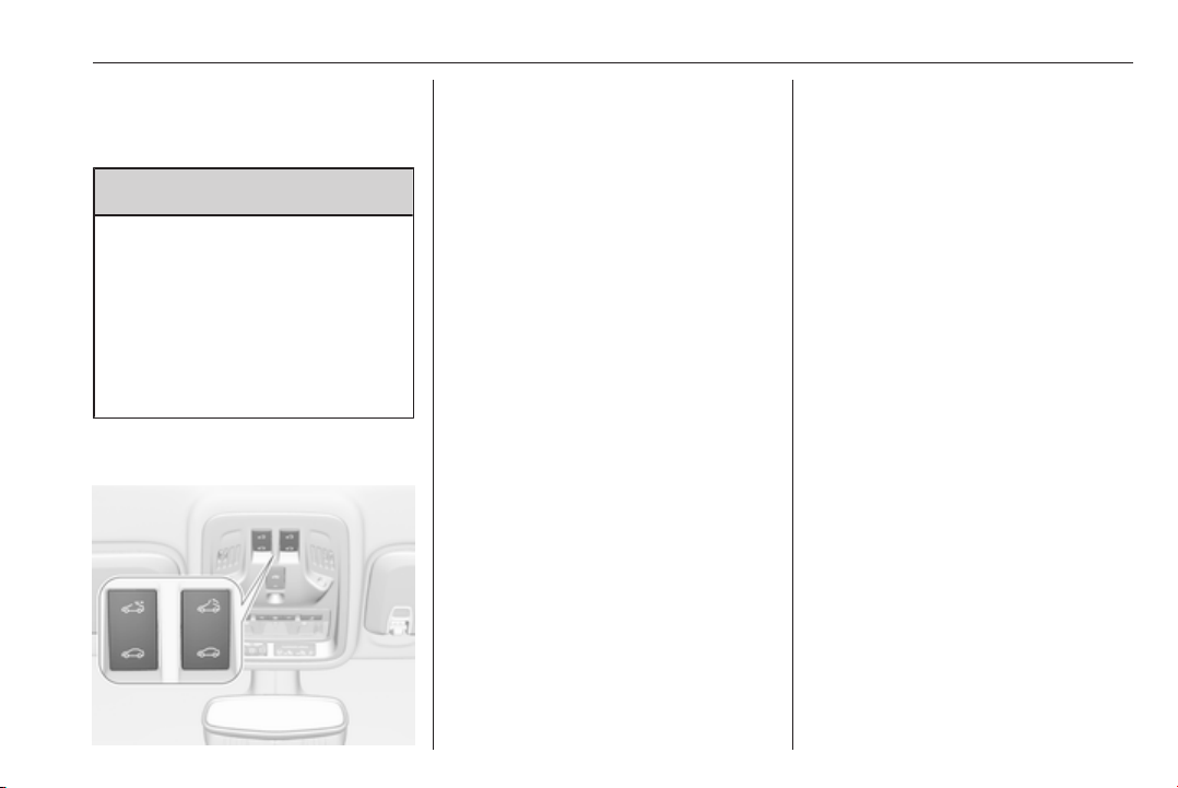
Switch on ignition to operate the
sunroof.
Open or close
Press p or r gently to the first
detent: sunroof is opened or closed
as long as the switch is operated.
Press p or r firmly to the second
detent then release: the sunroof is
opened or closed automatically.
During closing the safety function is
enabled. To stop movement, operate
the switch once more.
Raise or close
Press q or r: sunroof is raised or
closed automatically. During closing
the safety function is enabled.
Sunblind
The sunblind is manually operated.
Close or open the sunblind by sliding.
When the sunroof is open, the
sunblind is always open.
General hints
Safety function
If the sunroof encounters resistance
during automatic closing, it is
immediately stopped and opened
again.
Override safety function
In the event of closing difficulties, e.g.
due to frost, hold the switch r
pressed to the second detent. The
sunroof closes with safety function
disabled. To stop movement, release
the switch.
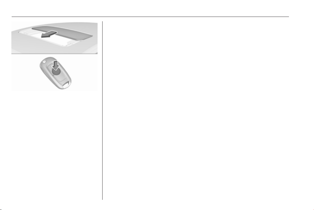
Closing sunroof from outside
The sunroof can be closed remotely
from outside the vehicle.
Page 48
46 Keys, doors and windows
Press and hold e to close the sunroof.
Release the button to stop the
movement.
Initialising after a power failure
After a power failure, it may only be
possible to operate the sunroof to a
limited extent. Have the system
initialised by your workshop.
Page 49

Seats, restraints 47
Seats, restraints
Head restraints ............................ 47
Front seats ................................... 48
Seat position .............................. 48
Manual seat adjustment ............ 49
Power seat adjustment .............. 51
Armrest ...................................... 54
Heating ...................................... 55
Ventilating .................................. 55
Massage .................................... 56
Rear seats ................................... 56
Armrest ...................................... 56
Heating ...................................... 57
Seat belts ..................................... 57
Three-point seat belt ................. 58
Airbag system .............................. 59
Front airbag system ................... 63
Side airbag system .................... 63
Curtain airbag system ............... 64
Airbag deactivation .................... 64
Child restraints ............................. 66
Child restraint systems .............. 66
Child restraint installation
locations ................................... 68
Head restraints
Position
9 Warning
Only drive with the head restraint
set to the proper position.
The upper edge of the head restraint
should be at upper head level. If this
is not possible for extremely tall
people, set to highest position, and
set to lowest position for small people.
Adjustment
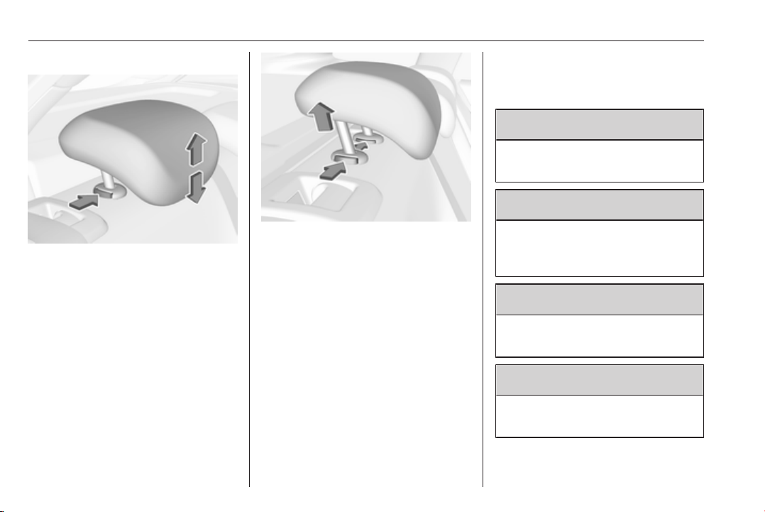
Head restraints on front seats
Height adjustment
Press release button, adjust height,
engage.
Page 50
48 Seats, restraints
Head restraints on rear seats
Height adjustment
Pull the head restraint upwards or
press the catch to release and push
the head restraint downwards.
Removal of rear head restraints
E.g. for load compartment extension
3 74.
Press both catches, pull the head
restraint upwards and remove.
Front seats
Seat position
9 Warning
Only drive with the seat correctly
adjusted.
9 Danger
Do not sit closer than 25 cm to the
steering wheel, to permit safe
airbag deployment.
9 Warning
Never adjust seats while driving as
they could move uncontrollably.
9 Warning
Never store any objects under the
seats.
Page 51
Seats, restraints 49
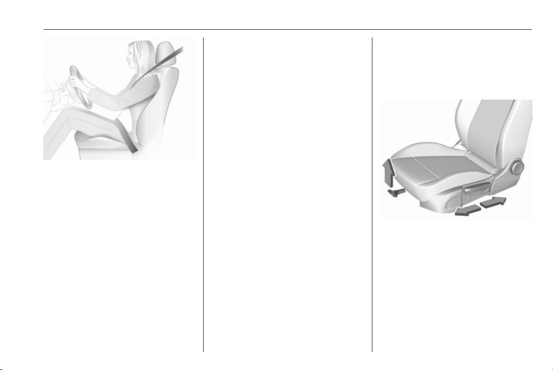
● Sit with buttocks as far back
against the backrest as possible.
Adjust the distance between the
seat and the pedals so that legs
are slightly angled when fully
pressing the pedals. Slide the
front passenger seat as far back
as possible.
● Set seat height high enough to
have a clear field of vision on all
sides and of all display
instruments. There should be at
least one hand of clearance
between head and the roof
frame. Your thighs should rest
lightly on the seat without
pressing into it.
● Sit with shoulders as far back
against the backrest as possible.
Set the backrest rake so that it is
possible to easily reach the
steering wheel with arms slightly
bent. Maintain contact between
shoulders and the backrest when
turning the steering wheel. Do
not angle the backrest too far
back. We recommend a
maximum rake of approx. 25°.
● Adjust seat and steering wheel in
a way that the wrist rests on top
of the steering wheel while the
arm is fully extended and
shoulders on the backrest.
● Adjust the steering wheel 3 92.
● Adjust the head restraint 3 47.
● Adjust the thigh support so that
there is a space approx. two
fingers wide between the edge of
the seat and the hollow of the
knee.
● Adjust the lumbar support so that
it supports the natural shape of
the spine.
Manual seat adjustment
Drive only with engaged seats and
backrests.
Longitudinal adjustment
Pull handle, slide seat, release
handle. Try to move the seat back and
forth to ensure that the seat is locked
in place.
Page 52
50 Seats, restraints
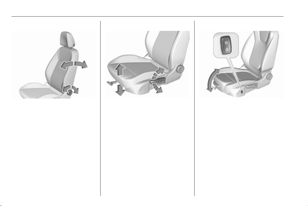
Backrest inclination
Turn handwheel. Do not lean on
backrest when adjusting.
Seat height
Lever pumping motion
up : seat higher
down : seat lower
Seat inclination
Press switch
top : front end higher
bottom : front end lower
Page 53
Seats, restraints 51
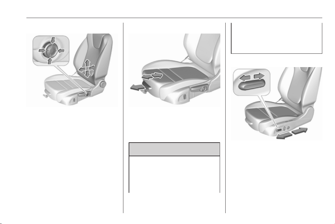
Lumbar support
Adjust lumbar support using the fourway switch to suit personal
requirements.
Moving support up and down: push
switch up or down.
Increasing and decreasing support:
push switch forwards or backwards.
Adjustable thigh support
Pull the lever and slide the thigh
support.
Power seat adjustment
9 Warning
Care must be taken when
operating the power seats. There
is a risk of injury, particularly for
children. Objects could become
trapped.
Keep a close watch on the seats
when adjusting them. Vehicle
passengers should be informed
accordingly.
Longitudinal adjustment
Move switch forwards/backwards.
Page 54
52 Seats, restraints
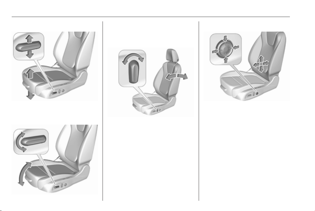
Seat height
Move switch upwards/downwards.
Seat inclination
Tilt front of switch upwards/
downwards.
Backrest inclination
Tilt switch forwards/backwards.
Lumbar support
Adjust lumbar support using the
four-way switch to suit personal
requirements.
Moving support up and down: push
switch up or down.
Increasing and decreasing support:
push switch forwards or backwards.
Page 55
Seats, restraints 53
Adjustable thigh support
Pull the lever and slide the thigh
support.
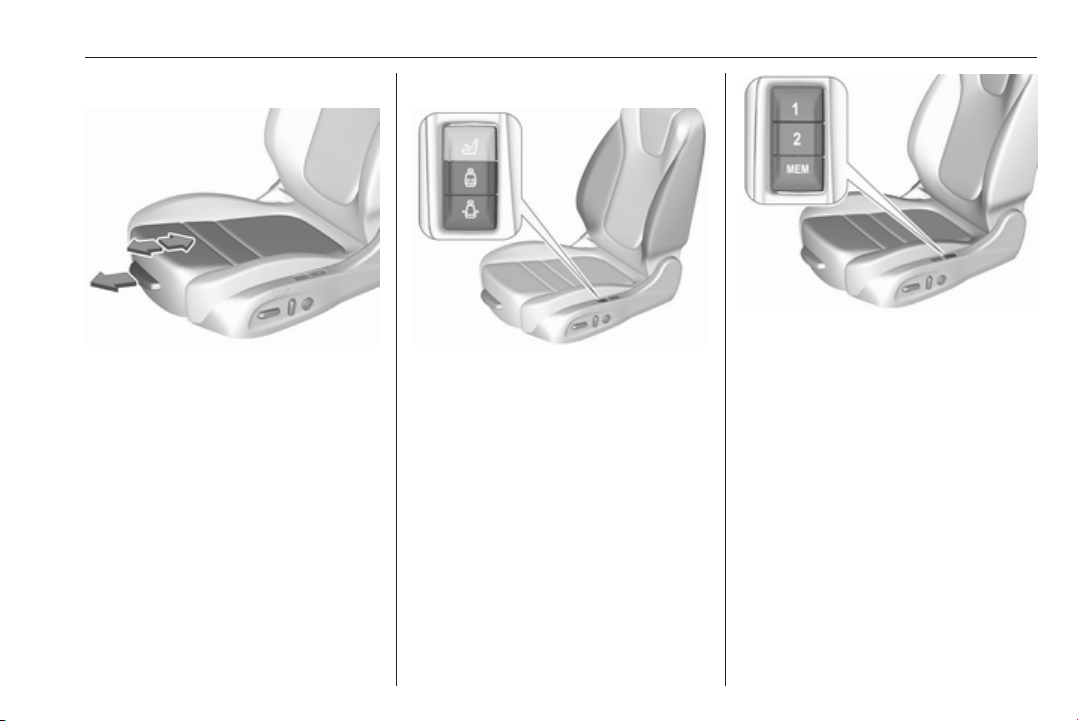
Side bolster
Adjust seat backrest width to suit
personal requirements.
Press e to reduce backrest width.
Press d to increase backrest width.
Memory function for power seat adjustment
Two different driver's seat settings
can be stored.
Memorised settings 3 25, Vehicle
personalisation 3 125.
Storing memory position
● Adjust driver's seat to desired
position.
● Press and hold MEM and 1 or 2
simultaneously until a chime
sounds.
Recall of memory positions
Press and hold 1 or 2 until the stored
seat position has been reached.
Releasing the button during seat
movement cancels the recall.
Automatic recall of memory positions
Memory positions are assigned to the
driver (1 or 2) using the respective key
and are automatically recalled when
Page 56
54 Seats, restraints
the ignition is switched on. In addition,
a message in the Driver Information
Centre indicates the driver number,
identified by the used key. If the
ignition is switched on more than
three subsequent times with the
same key, the message will not be
displayed again until another key is
being used.
To stop recall movement, press one
of the memory or power seat controls.
Precondition is that Personalisation
by Driver and Auto Memory Recall is
activated in the personal settings of
the Info-Display.
This function can be activated or
deactivated in the vehicle
personalisation.
Select the relevant setting in the
Vehicle menu in the Info-Display.
Info-Display 3 121.
Vehicle personalisation 3 125.
Easy exit function
For a convenient exit out of the
vehicle, the power driver seat moves
rearwards when vehicle is stationary.
To activate the easy exit function:
● set selector lever to position P
(automatic transmission)
● apply parking brake (manual
transmission)
● switch off ignition
● remove key from the ignition
switch
● open the driver's door
If the door is already open, switch off
ignition to activate easy exit.
To stop movement, press one of the
memory or power seat controls.
This function can be activated or
deactivated in the vehicle
personalisation.
Select the relevant setting in the
Vehicle menu in the Info-Display.
Info-Display 3 121.
Vehicle personalisation 3 125.
Safety function
If the driver's seat encounters
resistance during movement, the
recall may stop. After removing the
obstruction, press and hold the
appropriate memory position button
for two seconds. Try recalling the
memory position again. If the recall
does not operate, consult a
workshop.
Overload
If the seat setting is electrically
overloaded, the power supply is
automatically cut-off for a short time.
Note
After an accident in which airbags
have been deployed, the memory
function for each position button will
be deactivated.
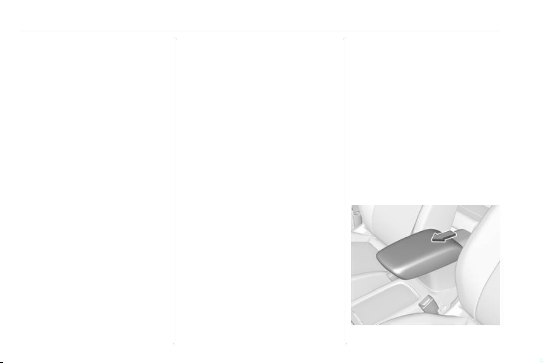
Armrest
Page 57
Seats, restraints 55
The armrest can be slid forwards by
10 cm. Under the armrest there is a
storage compartment.
Armrest storage 3 73.
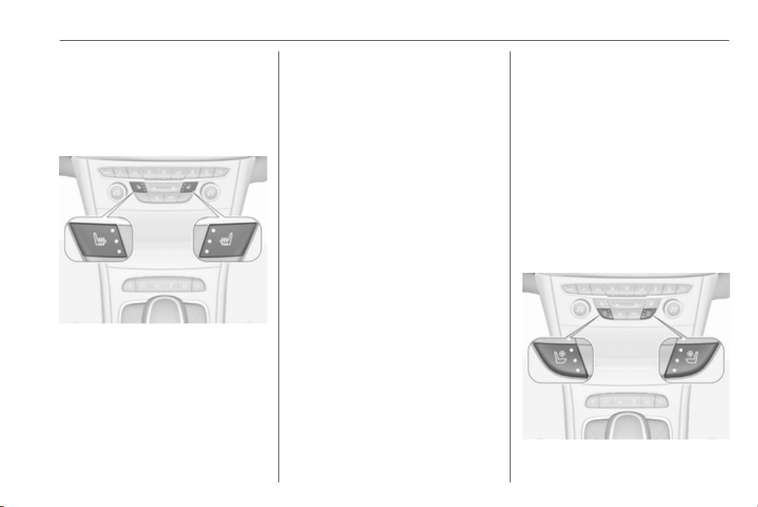
Heating
Adjust heating to the desired setting
by pressing ß for the respective seat
one or more times. The control
indicator in the button indicates the
setting.
Prolonged use of the highest setting
for people with sensitive skin is not
recommended.
The seat heating will be reduced
automatically from highest level to
medium level after 30 minutes.
Seat heating is operational when
engine is running and during an
Autostop.
Stop-start system 3 162.
Automatic seat heating
Depending on the equipment, the
automatic seat heating can be
enabled in the vehicle personalisation
menu in the Info-Display.
Vehicle personalisation 3 125.
When enabled, the heating of the
seats will be activated automatically
at vehicle start. The activation is
based on several parameters such as
vehicle interior temperature, intensity
and direction of the sun and
temperature setting of the electronic
climate control system for the driver
and passenger side.
As the vehicle’s interior warms up, the
seat heating level will be reduced
automatically until it finally goes off.
The seat heating level being provided
during the automatic operation is
shown by heated seat indicator lights.
If the passenger seat is unoccupied,
the automatic seat heating feature will
not activate the seat heating for that
seat.
The seat heating buttons can be
pressed at any time to exit the
automatic seat heating for the
respective seat and control the seat
heating manually instead.
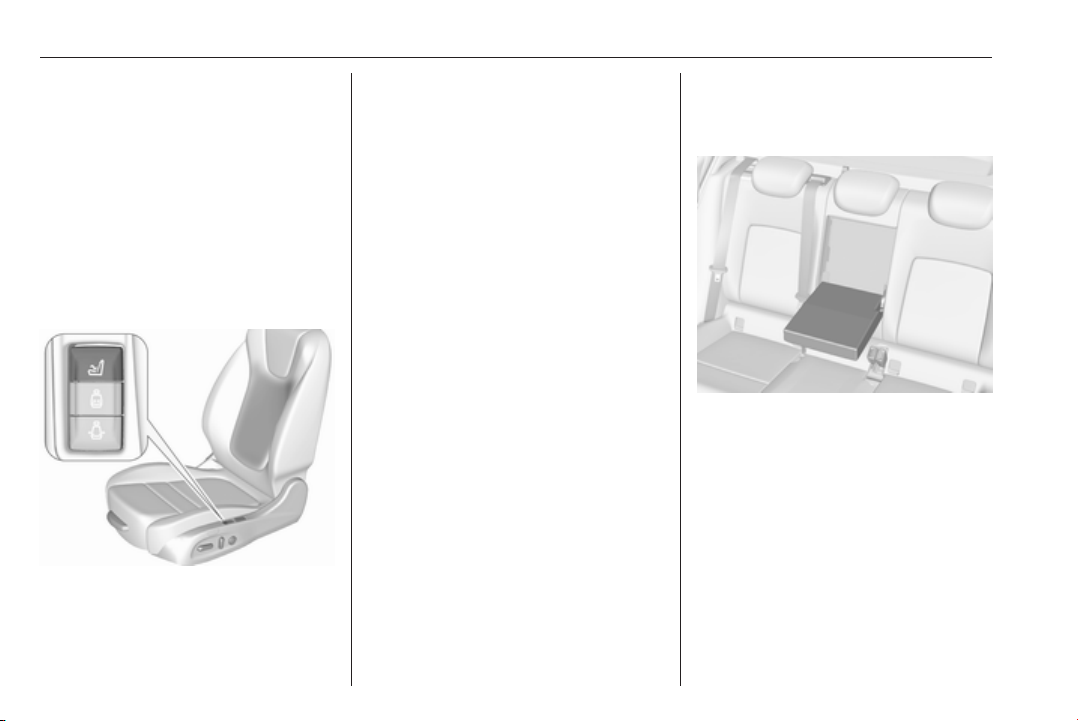
Ventilating
Page 58
56 Seats, restraints
Adjust ventilating to the desired
setting by pressing A for the
respective seat one or more times.
The control indicator in the button
indicates the setting.
Ventilated seats are operational when
engine is running and during an
Autostop.
Stop-start system 3 162.
Massage
Press c to switch on the back
massage function.
To switch off, press c again.
After ten minutes the massage
function is switched off automatically.
Rear seats
Armrest
Fold armrest down.
Page 59
Seats, restraints 57
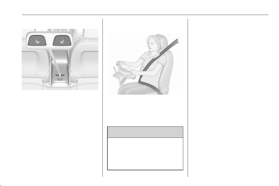
Heating
Activate seat heating by pressing ß
for the respective rear outer seat.
Activation is indicated by the LED in
the button.
Press ß once more to deactivate seat
heating.
Prolonged use for people with
sensitive skin is not recommended.
Seat heating is operational when
engine is running and during an
Autostop.
Stop-start system 3 162.
Seat belts
The seat belts are locked during
heavy acceleration or deceleration of
the vehicle, holding the occupants in
the seat position. Thereby the risk of
injury is considerably reduced.
9 Warning
Fasten seat belt before each trip.
In the event of an accident, people
not wearing seat belts endanger
their fellow occupants and
themselves.
Seat belts are designed to be used by
only one person at a time. Child
restraint system 3 66.
Periodically check all parts of the belt
system for damage, soiling and
proper functionality.
Have damaged components replaced
by a workshop. After an accident,
have the belts and triggered belt
pretensioners replaced by a
workshop.
Note
Make sure that the belts are not
damaged by shoes or sharp-edged
objects or trapped. Prevent dirt from
getting into the belt retractors.
Seat belt reminder
Each seat is equipped with a seat belt
reminder, indicated for front seats by
control indicators X and k, or for rear
seats by the symbol X in the Driver
Information Centre 3 108.
Belt force limiters
Stress on the body is reduced by the
gradual release of the belt during a
collision.
Page 60
58 Seats, restraints
Belt pretensioners
In the event of a head-on, rear-end or
side-on collision of a certain severity,
the front and rear outboard seat belts
are tightened. The front seat belts and
the outer seat belts are tightened by
one pretensioner per seat.
9 Warning
Incorrect handling (e.g. removal or
fitting of belts) can trigger the belt
pretensioners.
Deployment of the belt pretensioners
is indicated by continuous illumination
of control indicator v 3 109.
Triggered belt pretensioners must be
replaced by a workshop. Belt
pretensioners can only be triggered
once.
Note
Do not affix or install accessories or
other objects that may interfere with
the operation of the belt tensioner.
Do not make any modification to belt
tensioner components as this will
invalidate the vehicle operating
permit.
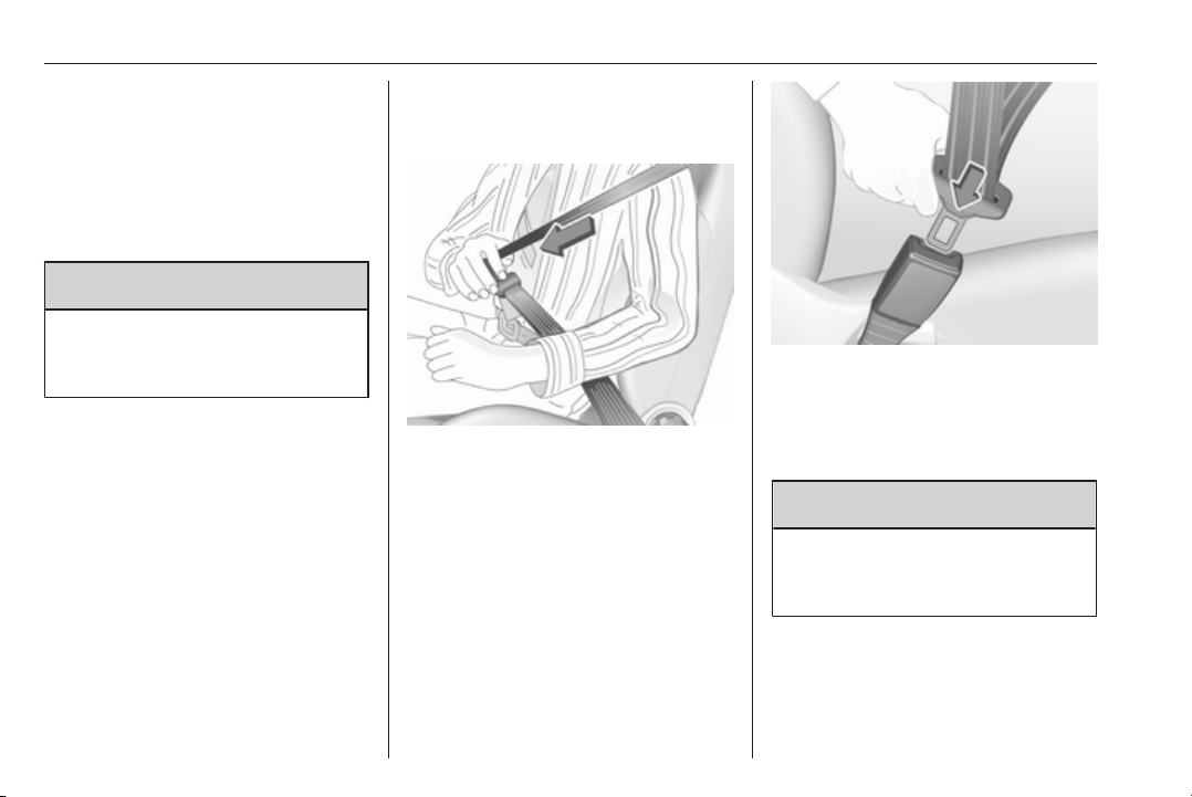
Three-point seat belt
Fasten
Withdraw the belt from the retractor,
guide it untwisted across the body
and insert the latch plate into the
buckle. Tighten the lap belt regularly
whilst driving by pulling the shoulder
belt.
Loose or bulky clothing prevents the
belt from fitting snugly. Do not place
objects such as handbags or mobile
phones between the belt and your
body.
9 Warning
The belt must not rest against hard
or fragile objects in the pockets of
your clothing.
Seat belt reminder X, k 3 108.
Page 61
Seats, restraints 59
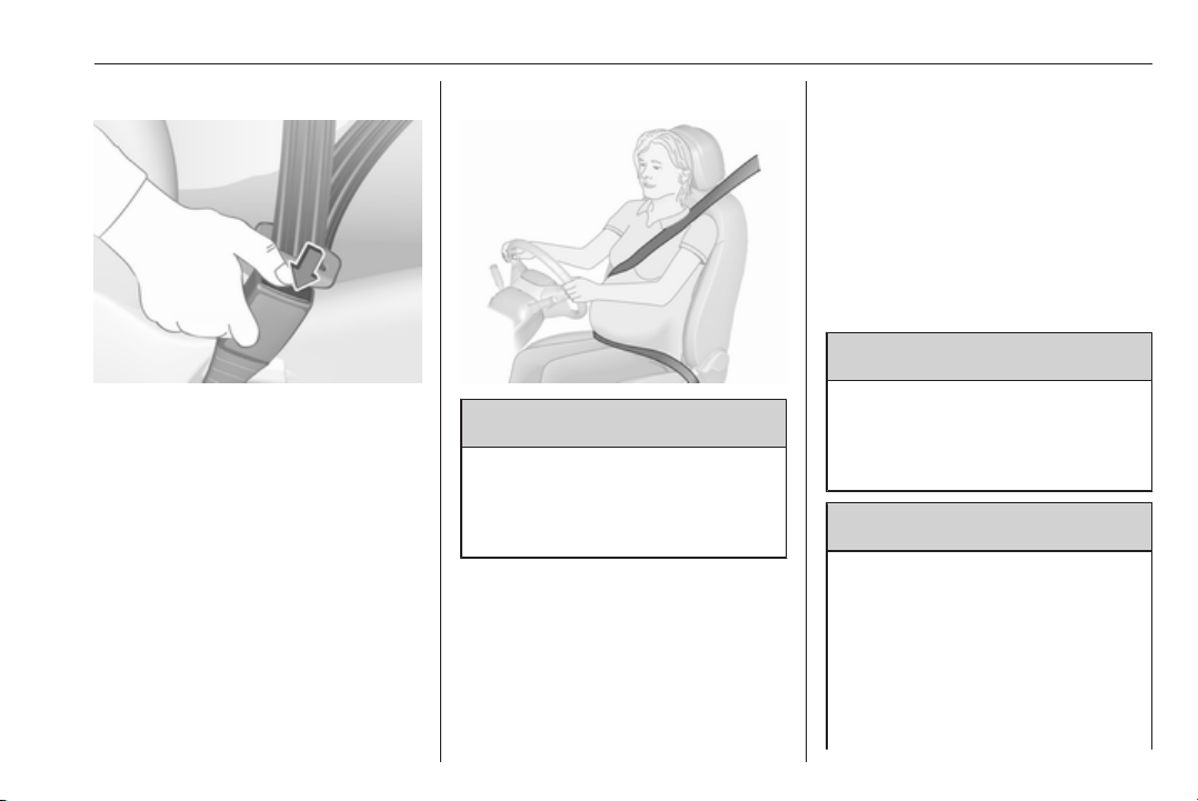
Unfasten
To release belt, press red button on
belt buckle.
Using the seat belt while pregnant
9 Warning
The lap belt must be positioned as
low as possible across the pelvis
to prevent pressure on the
abdomen.
Airbag system
The airbag system consists of a
number of individual systems
depending on the scope of
equipment.
When triggered, the airbags inflate
within milliseconds. They also deflate
so quickly that it is often unnoticeable
during the collision.
9 Warning
The airbag system deploys in an
explosive manner, repairs must be
performed by skilled personnel
only.
9 Warning
Adding accessories that change
the vehicle's frame, bumper
system, height, front end or side
sheet metal, may keep the airbag
system from working properly. The
operation of the airbag system can
also be affected by changing any
parts of the front seats, seat belts,
Page 62
60 Seats, restraints
airbag sensing and diagnostic
module, steering wheel,
instrument panel, inner door seals
including the speakers, any of the
airbag modules, ceiling or pillar
trim, front sensors, side impact
sensors or airbag wiring.
Note
The airbag systems and belt
pretensioner control electronics are
located in the centre console area.
Do not put any magnetic objects in
this area.
Do not affix any objects onto the
airbag covers and do not cover them
with other materials. Have damaged
covers replaced by a workshop.
Each airbag is triggered only once.
Have deployed airbags replaced by
a workshop. Furthermore, it may be
necessary to have the steering
wheel, the instrument panel, parts of
the panelling, the door seals,
handles and the seats replaced.
Do not make any modifications to
the airbag system as this will
invalidate the vehicle operating
permit.
Control indicator v for airbag systems
3 109.
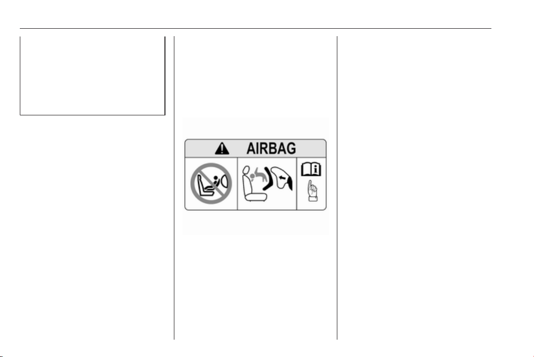
Child restraint systems on front
passenger seat with airbag
systems
Warning according to ECE R94.02:
NEVER use a rearward-facing
EN:
child restraint on a seat protected by
an ACTIVE AIRBAG in front of it;
DEATH or SERIOUS INJURY to the
CHILD can occur.
DE: Nach hinten gerichtete
Kindersitze NIEMALS auf einem Sitz
verwenden, der durch einen davor
befindlichen AKTIVEN AIRBAG
geschützt ist, da dies den TOD oder
SCHWERE VERLETZUNGEN DES
KINDES zur Folge haben kann.
FR: NE JAMAIS utiliser un siège
d'enfant orienté vers l'arrière sur un
siège protégé par un COUSSIN
GONFLABLE ACTIF placé devant lui,
sous peine d'infliger des
BLESSURES GRAVES, voire
MORTELLES à l'ENFANT.
ES: NUNCA utilice un sistema de
retención infantil orientado hacia
atrás en un asiento protegido por un
AIRBAG FRONTAL ACTIVO. Peligro
de MUERTE o LESIONES GRAVES
para el NIÑO.
RU: ЗАПРЕЩАЕТСЯ
устанавливать детское
удерживающее устройство лицом
назад на сиденье автомобиля,
оборудованном фронтальной
подушкой безопасности, если
ПОДУШКА НЕ ОТКЛЮЧЕНА! Это
может привести к СМЕРТИ или
СЕРЬЕЗНЫМ ТРАВМАМ
РЕБЕНКА.
Page 63

Seats, restraints 61
NL: Gebruik NOOIT een achterwaarts
gericht kinderzitje op een stoel met
een ACTIEVE AIRBAG ervoor, om
DODELIJK of ERNSTIG LETSEL van
het KIND te voorkomen.
DA: Brug ALDRIG en bagudvendt
autostol på et forsæde med AKTIV
AIRBAG, BARNET kan komme i
LIVSFARE eller komme ALVORLIGT
TIL SKADE.
SV: Använd ALDRIG en bakåtvänd
barnstol på ett säte som skyddas med
en framförvarande AKTIV AIRBAG.
DÖDSFALL eller ALLVARLIGA
SKADOR kan drabba BARNET.
FI: ÄLÄ KOSKAAN sijoita taaksepäin
suunnattua lasten turvaistuinta
istuimelle, jonka edessä on
AKTIIVINEN TURVATYYNY, LAPSI
VOI KUOLLA tai VAMMAUTUA
VAKAVASTI.
NO: Bakovervendt
barnesikringsutstyr må ALDRI brukes
på et sete med AKTIV
KOLLISJONSPUTE foran, da det kan
føre til at BARNET utsettes for
LIVSFARE og fare for ALVORLIGE
SKADER.
PT: NUNCA use um sistema de
retenção para crianças voltado para
trás num banco protegido com um
AIRBAG ACTIVO na frente do
mesmo, poderá ocorrer a PERDA DE
VIDA ou FERIMENTOS GRAVES na
CRIANÇA.
IT: Non usare mai un sistema di
sicurezza per bambini rivolto
all'indietro su un sedile protetto da
AIRBAG ATTIVO di fronte ad esso:
pericolo di MORTE o LESIONI
GRAVI per il BAMBINO!
EL: ΠΟΤΕ μη χρησιμοποιείτε παιδικό
κάθισμα ασφαλείας με φορά προς τα
πίσω σε κάθισμα που προστατεύεται
από μετωπικό ΕΝΕΡΓΟ ΑΕΡΟΣΑΚΟ,
διότι το παιδί μπορεί να υποστεί
ΘΑΝΑΣΙΜΟ ή ΣΟΒΑΡΟ
ΤΡΑΥΜΑΤΙΣΜΟ.
PL: NIE WOLNO montować fotelika
dziecięcego zwróconego tyłem do
kierunku jazdy na fotelu, przed
którym znajduje się WŁĄCZONA
PODUSZKA POWIETRZNA.
Niezastosowanie się do tego
zalecenia może być przyczyną
ŚMIERCI lub POWAŻNYCH
OBRAŻEŃ u DZIECKA.
TR: Arkaya bakan bir çocuk emniyet
sistemini KESİNLİKLE önünde bir
AKTİF HAVA YASTIĞI ile
korunmakta olan bir koltukta
kullanmayınız. ÇOCUK ÖLEBİLİR
veya AĞIR ŞEKİLDE
YARALANABİLİR.
UK: НІКОЛИ не використовуйте
систему безпеки для дітей, що
встановлюється обличчям назад,
на сидінні з УВІМКНЕНОЮ
ПОДУШКОЮ БЕЗПЕКИ, інакше це
може призвести до СМЕРТІ чи
СЕРЙОЗНОГО ТРАВМУВАННЯ
ДИТИНИ.
HU: SOHA ne használjon hátrafelé
néző biztonsági gyerekülést előlről
AKTÍV LÉGZSÁKKAL védett ülésen,
mert a GYERMEK HALÁLÁT vagy
KOMOLY SÉRÜLÉSÉT okozhatja.
HR: NIKADA nemojte koristiti sustav
zadržavanja za djecu okrenut prema
natrag na sjedalu s AKTIVNIM
ZRAČNIM JASTUKOM ispred njega,
to bi moglo dovesti do SMRTI ili
OZBILJNJIH OZLJEDA za DIJETE.
SL: NIKOLI ne nameščajte otroškega
varnostnega sedeža, obrnjenega v
nasprotni smeri vožnje, na sedež z
Page 64

62 Seats, restraints
AKTIVNO ČELNO ZRAČNO
BLAZINO, saj pri tem obstaja
nevarnost RESNIH ali SMRTNIH
POŠKODB za OTROKA.
SR: NIKADA ne koristiti bezbednosni
sistem za decu u kome su deca
okrenuta unazad na sedištu sa
AKTIVNIM VAZDUŠNIM
JASTUKOM ispred sedišta zato što
DETE može da NASTRADA ili da se
TEŠKO POVREDI.
MK: НИКОГАШ не користете детско
седиште свртено наназад на
седиште заштитено со АКТИВНО
ВОЗДУШНО ПЕРНИЧЕ пред него,
затоа што детето може ДА ЗАГИНЕ
или да биде ТЕШКО ПОВРЕДЕНО.
BG: НИКОГА не използвайте
детска седалка, гледаща назад,
върху седалка, която е защитена
чрез АКТИВНА ВЪЗДУШНА
ВЪЗГЛАВНИЦА пред нея - може да
се стигне до СМЪРТ или
СЕРИОЗНО НАРАНЯВАНЕ на
ДЕТЕТО.
RO: Nu utilizaţi NICIODATĂ un scaun
pentru copil îndreptat spre partea din
spate a maşinii pe un scaun protejat
de un AIRBAG ACTIV în faţa sa;
acest lucru poate duce la DECESUL
sau VĂTĂMAREA GRAVĂ a
COPILULUI.
CS: NIKDY nepoužívejte dětský
zádržný systém instalovaný proti
směru jízdy na sedadle, které je
chráněno před sedadlem AKTIVNÍM
AIRBAGEM. Mohlo by dojít k
VÁŽNÉMU PORANĚNÍ nebo ÚMRTÍ
DÍTĚTE.
SK: NIKDY nepoužívajte detskú
sedačku otočenú vzad na sedadle
chránenom AKTÍVNYM AIRBAGOM,
pretože môže dôjsť k SMRTI alebo
VÁŽNYM ZRANENIAM DIEŤAŤA.
LT: JOKIU BŪDU nemontuokite atgal
atgręžtos vaiko tvirtinimo sistemos
sėdynėje, prieš kurią įrengta AKTYVI
ORO PAGALVĖ, nes VAIKAS GALI
ŽŪTI arba RIMTAI SUSIŽALOTI.
LV: NEKĀDĀ GADĪJUMĀ
neizmantojiet uz aizmuguri vērstu
bērnu sēdeklīti sēdvietā, kas tiek
aizsargāta ar tās priekšā uzstādītu
AKTĪVU DROŠĪBAS SPILVENU, jo
pretējā gadījumā BĒRNS var gūt
SMAGAS TRAUMAS vai IET BOJĀ.
ET: ÄRGE kasutage tahapoole
suunatud lapseturvaistet istmel, mille
ees on AKTIIVSE TURVAPADJAGA
kaitstud iste, sest see võib
põhjustada LAPSE SURMA või
TÕSISE VIGASTUSE.
MT: QATT tuża trażżin għat-tfal li
jħares lejn in-naħa ta’ wara fuq sit
protett b’AIRBAG ATTIV quddiemu;
dan jista’ jikkawża l-MEWT jew
ĠRIEĦI SERJI lit-TFAL.
GA: Ná húsáid srian sábháilteachta
linbh cúil RIAMH ar shuíochán a
bhfuil mála aeir ag feidhmiú os a
chomhair. Tá baol BÁIS nó GORTÚ
DONA don PHÁISTE ag baint leis.
Beyond the warning required by
ECE R94.02, for safety reasons a
forward-facing child restraint system
must only be used subject to the
instructions and restrictions in the
table 3 68.
The airbag label is located on both
sides of the front passenger sun visor.
Airbag deactivation 3 64.
Page 65
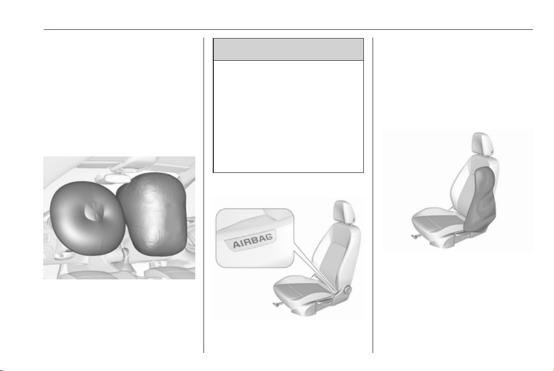
Seats, restraints 63
Front airbag system
The front airbag system consists of
one airbag in the steering wheel and
one in the instrument panel on the
front passenger side. These can be
identified by the word AIRBAG.
The front airbag system is triggered in
the event of a front-end impact of a
certain severity. The ignition must be
switched on.
The inflated airbags cushion the
impact, thereby reducing the risk of
injury to the upper body and head of
the front seat occupants
considerably.
Warning
9
Optimum protection is only
provided when the seat is in the
proper position.
Seat position 3 48.
Keep the area in which the airbag
inflates clear of obstructions.
Fit the seat belt correctly and
engage securely. Only then is the
airbag able to protect.
Side airbag system
The side airbag system consists of an
airbag in each front seat backrest.
This can be identified by the word
AIRBAG.
The side airbag system is triggered in
the event of a side impact of a certain
severity. The ignition must be
switched on.
The inflated airbags cushion the
impact, thereby reducing the risk of
injury to the upper body and pelvis in
the event of a side-on collision
considerably.
Page 66

64 Seats, restraints
9 Warning
Keep the area in which the airbag
inflates clear of obstructions.
Note
Only use protective seat covers that
have been approved for the vehicle.
Be careful not to cover the airbags.
Curtain airbag system
The curtain airbag system consists of
an airbag in the roof frame on each
side. This can be identified by the
word AIRBAG on the roof pillars.
The curtain airbag system is triggered
in the event of a side-on impact of a
certain severity. The ignition must be
switched on.
The inflated airbags cushion the
impact, thereby reducing the risk of
injury to the head in the event of a
side-on impact considerably.
9 Warning
Keep the area in which the airbag
inflates clear of obstructions.
The hooks on the handles in the
roof frame are only suitable for
hanging up light articles of
clothing, without coat hangers. Do
not keep any items in these
clothes.
Airbag deactivation
The front passenger airbag system
must be deactivated for child restraint
system on the passenger seat
according to the instructions in the
table 3 68. The side airbag and
curtain airbag systems, the belt
pretensioners and all driver airbag
systems will remain active.
The front passenger airbag system
can be deactivated via a keyoperated switch on the passenger
side of the instrument panel.
Page 67
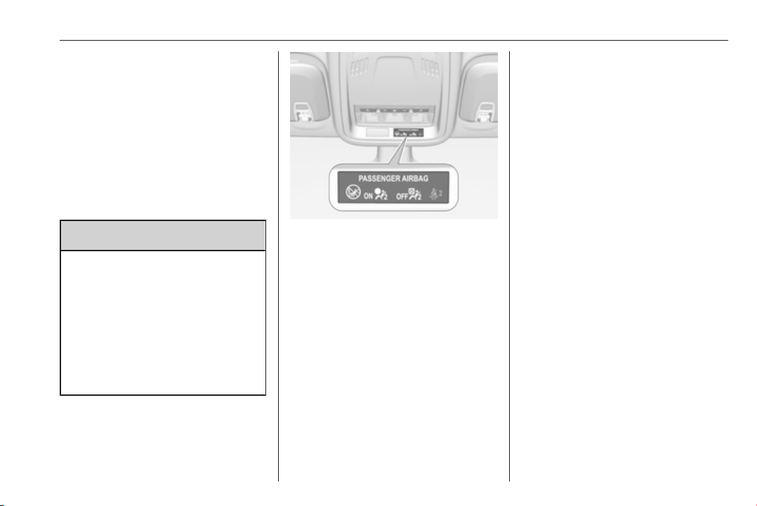
Seats, restraints 65
Use the ignition key to choose the
position:
*OFF
VON : front passenger airbag is
: front passenger airbag is
deactivated and will not
inflate in the event of a
collision. Control indicator
*OFF illuminates
continuously in the
overhead console.
active
9 Danger
Deactivate passenger airbag only
in combination with the use of a
child restraint system, subject to
the instructions and restrictions in
the table 3 68.
Otherwise, there is a risk of fatal
injury for a person occupying a
seat with a deactivated front
passenger airbag.
Status remains until the next change.
Control indicator for airbag
deactivation 3 109.
If the control indicator V illuminates
for approx. 60 seconds after the
ignition is switched on, the front
passenger airbag system will inflate
in the event of a collision.
If both control indicators are
illuminated at the same time, there is
a system failure. The status of the
system is not discernible, therefore
no person is allowed to occupy the
front passenger seat. Contact a
workshop immediately.
Consult a workshop immediately if
neither of the two control indicators
are illuminated.
Change status only when the vehicle
is stopped with the ignition off.
Page 68
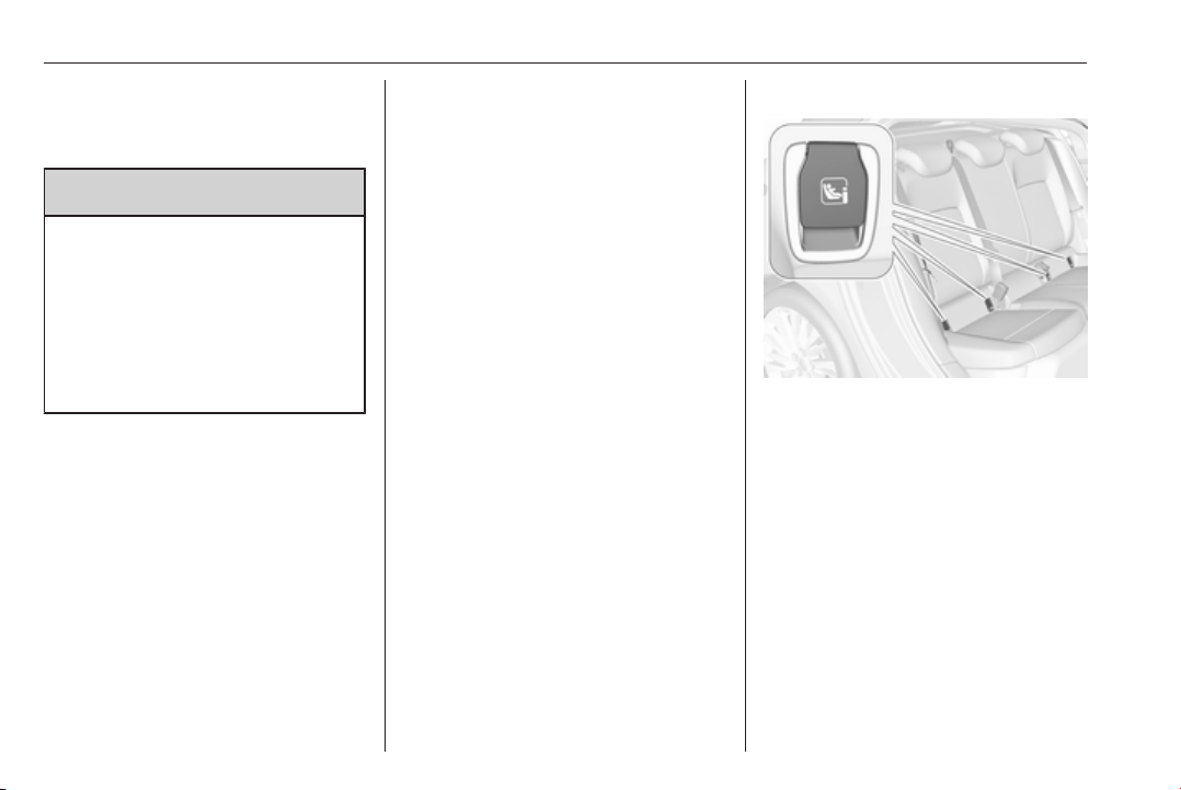
66 Seats, restraints
Child restraints
Child restraint systems
9 Danger
If using a rear-facing child restraint
system on the front passenger
seat, the airbag system for the
front passenger seat must be
deactivated. This also applies to
certain forward-facing child
restraint systems as indicated in
the tables 3 68.
Airbag deactivation 3 64.
Airbag label 3 59.
We recommend a child restraint
system which is tailored specifically to
the vehicle. For further information,
contact your workshop.
When a child restraint system is being
used, pay attention to the following
usage and installation instructions as
well as to those supplied with the child
restraint system.
Always comply with local or national
regulations. In some countries, the
use of child restraint systems is
forbidden on certain seats.
Child restraint systems can be
fastened with:
● Three-point seat belt
● ISOFIX brackets
● Top-tether anchor
Three-point seat belt
Child restraint systems can be
fastened by using a three-point seat
belt. Depending on the size of the
used child restraint systems, up to
three child restraint systems can be
attached to the rear seats. After
fastening the child restraint system
the seat belt has to be
tightened3 68.
ISOFIX brackets
Fasten vehicle-approved ISOFIX
child restraint systems to the ISOFIX
mounting brackets. Specific vehicle
ISOFIX child restraint system
positions are marked in the ISOFIX
table 3 68.
ISOFIX mounting brackets are
indicated by a label on the backrest.
An i-size child restraint system is an
universal ISOFIX child restraint
system according UN Regulation No.
129.
All i-size child restraint systems can
be used on any vehicle seat suitable
for i-size, i-size table 3 68.
Page 69
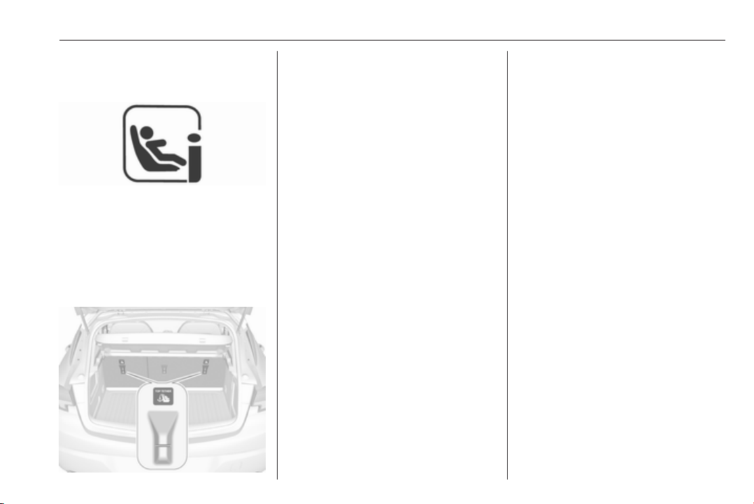
Seats, restraints 67
Either a Top-tether strap or a support
leg must be used in addition to the
ISOFIX mounting brackets.
i-size child seats and vehicle seats
with i-size approval are marked with
i-size symbol, see illustration.
Top-tether anchors
Top-tether anchors are marked with
the symbol : for a child seat.
In addition to the ISOFIX mounting
brackets, fasten the Top-tether strap
to the Top-tether anchors.
ISOFIX child restraint systems of
universal category positions are
marked in the table by IUF 3 68.
Selecting the right system
The rear seats are the most
convenient location to fasten a child
restraint system.
Children should travel facing
rearwards in the vehicle as long as
possible. This makes sure that the
child's backbone, which is still very
weak, is under less strain in the event
of an accident.
Suitable are restraint systems that
comply with valid UN ECE
regulations. Check local laws and
regulations for mandatory use of child
restraint systems.
The following child restraints are
recommended for the following
weight classes:
Maxi Cosi Cabriofix for children up to
13 kg for group 0, group 0+ and Duo
Plus for children from 13 kg to 18 kg
in group I.
Ensure that the child restraint system
to be installed is compatible with the
vehicle type.
Ensure that the mounting location of
the child restraint system within the
vehicle is correct, see following
tables.
Allow children to enter and exit the
vehicle only on the side facing away
from the traffic.
When the child restraint system is not
in use, secure the seat with a seat belt
or remove it from the vehicle.
Note
Do not affix anything on the child
restraint systems and do not cover
them with any other materials.
A child restraint system which has
been subjected to stress in an
accident must be replaced.
Page 70

68 Seats, restraints
Child restraint installation locations
Permissible options for fastening a child restraint system with a three-point seat belt
On front passenger seat
Weight class
Group 0: up to 10 kg X
Group 0+: up to 13 kg X
Group I: 9 to 18 kg X
Group II: 15 to 25 kg
Group III: 22 to 36 kg
1,2
U
1,2
U
1,2
U
1,2
U
1,2
U
X
X
U : universal suitability in conjunction with three-point seat belt
L : suitable for particular child restraint systems of the 'specific-vehicle', 'restricted' or 'semi-universal' categories. The
child restraint system must be approved for the specific vehicle type (refer to the vehicle type list of the child restraint
system)
X : no child restraint system permitted in this weight class
1
: move seat forwards as far as necessary and adjust seat backrest as far as necessary to a vertical position to ensure
that the belt runs forwards from the upper anchorage point
2
: move seat upwards as far as necessary and adjust seat backrest as far as necessary to a vertical position to ensure
that the belt is tight on the buckle side
3
: move the respective front seat ahead of the child restraint system forwards as far as necessary
4
: adjust the respective headrest as necessary or remove if required
On rear outboard seats On rear centre seatactivated airbag deactivated airbag
U/L
U/L
U/L
U/L
U/L
3
3
3,4
3,4
3,4
U
U
4
U
4
U
4
U
Page 71

Seats, restraints 69
Permissible options for fitting an ISOFIX child restraint system with ISOFIX brackets
On front passenger seat
Weight class Size class Fixture
On rear outboard
seats
Group 0: up to 10 kg G ISO/L2 X X X X
F ISO/L1 X X X X
E ISO/R1 X X
Group 0+: up to 13 kg E ISO/R1 X X
D ISO/R2 X X
C ISO/R3 X X
Group I: 9 to 18 kg D ISO/R2 X X
C ISO/R3 X X
B ISO/F2 X X
B1 ISO/F2X X X
A ISO/F3 X X
Group II: 15 to 25 kg X X
Group III: 22 to 36 kg X X
3
IL
3
IL
3
IL
3
IL
3,4
IL
3,4
IL
IL, IUF
IL, IUF
IL, IUF
3,4
IL
3,4
IL
3,4
3,4
3,4
On rear centre
seatactivated airbag deactivated airbag
X
X
X
X
X
X
X
X
X
X
X
Page 72

70 Seats, restraints
IL : suitable for particular ISOFIX restraint systems of the 'specific-vehicle', 'restricted' or 'semi-universal' categories.
The ISOFIX restraint system must be approved for the specific vehicle type (refer to the vehicle type list of the child
restraint system)
IUF : suitable for ISOFIX forward-facing child restraint systems of universal category approved for use in this weight class
X : no ISOFIX child restraint system approved in this weight class
1
: move seat forwards as far as necessary and adjust seat backrest inclination as far as necessary to a vertical position
to ensure that the belt runs forwards from the upper anchorage point
2
: move seat height adjustment upwards as far as necessary and adjust seat backrest inclination as far as necessary
to a vertical position to ensure that the belt is tight on the buckle side
3
: move the respective front seat ahead of the child restraint system forwards as far as necessary
4
: adjust the respective headrest as necessary or remove if required
ISOFIX size class and seat device
A – ISO/F3 : forward-facing child restraint system for children of maximum size in the weight class 9 to 18 kg
B – ISO/F2 : forward-facing child restraint system for smaller children in the weight class 9 to 18 kg
B1 – ISO/F2X : forward-facing child restraint system for smaller children in the weight class 9 to 18 kg
C – ISO/R3 : rear-facing child restraint system for children of maximum size in the weight class up to 18 kg
D – ISO/R2 : rear-facing child restraint system for smaller children in the weight class up to 18 kg
E – ISO/R1 : rear-facing child restraint system for young children in the weight class up to 13 kg
F– ISO/L1 : left lateral facing position child restraint system (carry-cot)
G – ISO/L2 : right lateral facing position child restraint system (carry-cot)
Permissible options for fitting an i-Size child restraint system with ISOFIX brackets
On front passenger seat
On rear outboard seats On rear centre seatactivated airbag deactivated airbag
i-Size child restraint systems X X i - U X
Page 73

i - U : suitable for i-Size 'universal' forward and rearward facing child restraint systems
X : seating position not suitable for i-Size 'universal' child restraint systems
Seats, restraints 71
Page 74
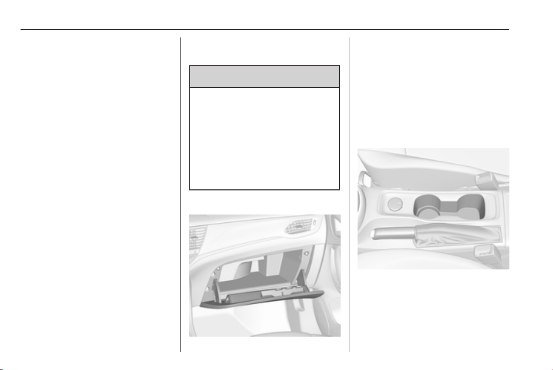
72 Storage
Storage
Storage compartments ................ 72
Glovebox ................................... 72
Cupholders ................................ 72
Front storage ............................. 73
Armrest storage ......................... 73
Load compartment ....................... 74
Rear storage .............................. 80
Load compartment cover ........... 80
Rear floor storage cover ............ 82
Lashing eyes ............................. 82
Cargo management system ......83
Safety net .................................. 85
Warning triangle ........................ 87
First aid kit ................................. 88
Roof rack system ......................... 89
Roof rack ................................... 89
Loading information ..................... 89
Storage compartments
9 Warning
Do not store heavy or sharp
objects in the storage
compartments. Otherwise, the
storage compartment lid could
open and vehicle occupants could
be injured by objects being thrown
around in the event of hard
braking, a sudden change in
direction or an accident.
Glovebox
The glovebox features a pen holder,
a coin holder and an adapter for the
locking wheel nuts.
The glovebox may also contain a CD
player.
The glovebox should be closed whilst
driving.
Cupholders
Cupholders are located in the centre
console.
Page 75

Storage 73
Depending on the version,
cupholders are located under a cover
in the centre console. Slide cover
backwards.
Front storage
A storage compartment is located
next to the steering wheel.
A combined storage and mobile
device compartment is located in the
instrument panel center stack.
Armrest storage
Storage under the front armrest
Press button to fold up the armrest.
The armrest must be in rearmost
position.
Page 76
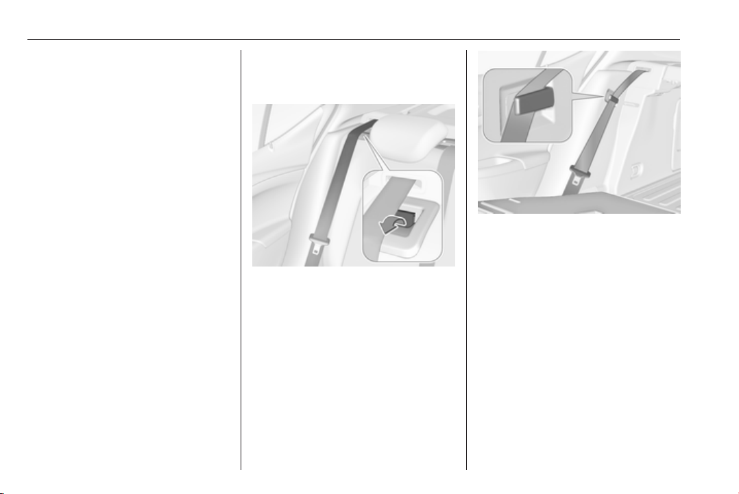
74 Storage
Load compartment
Depending on the equipment, the
rear seat backrest is divided into two
or three parts. All parts can be folded
down.
Before folding rear seat backrests,
execute the following if necessary:
● 5-door hatchback: remove the
load compartment cover 3 80.
● Sports Tourer: remove roller
blind 3 80.
● Press and hold the catch to push
the head restraints down 3 47.
● Remove the rear head restraints
to have the backrests fully rest on
the seat cushions 3 47.
Load compartment extension
(two-part rear seat backrest), 5door Hatchback
● Guide the seat belts of the outer
seats through side supports to
protect them against damage.
When folding the backrests, pull
the seat belts along with them.
● Pull the release lever on one or
both outer sides and fold down
the backrests onto the seat
cushion.
● Take the seat belt out of the seat
backrest guide and put it behind
the retainer as shown in the
illustration.
● To fold up, raise the backrests
and guide them into an upright
position until they engage
audibly.
Page 77
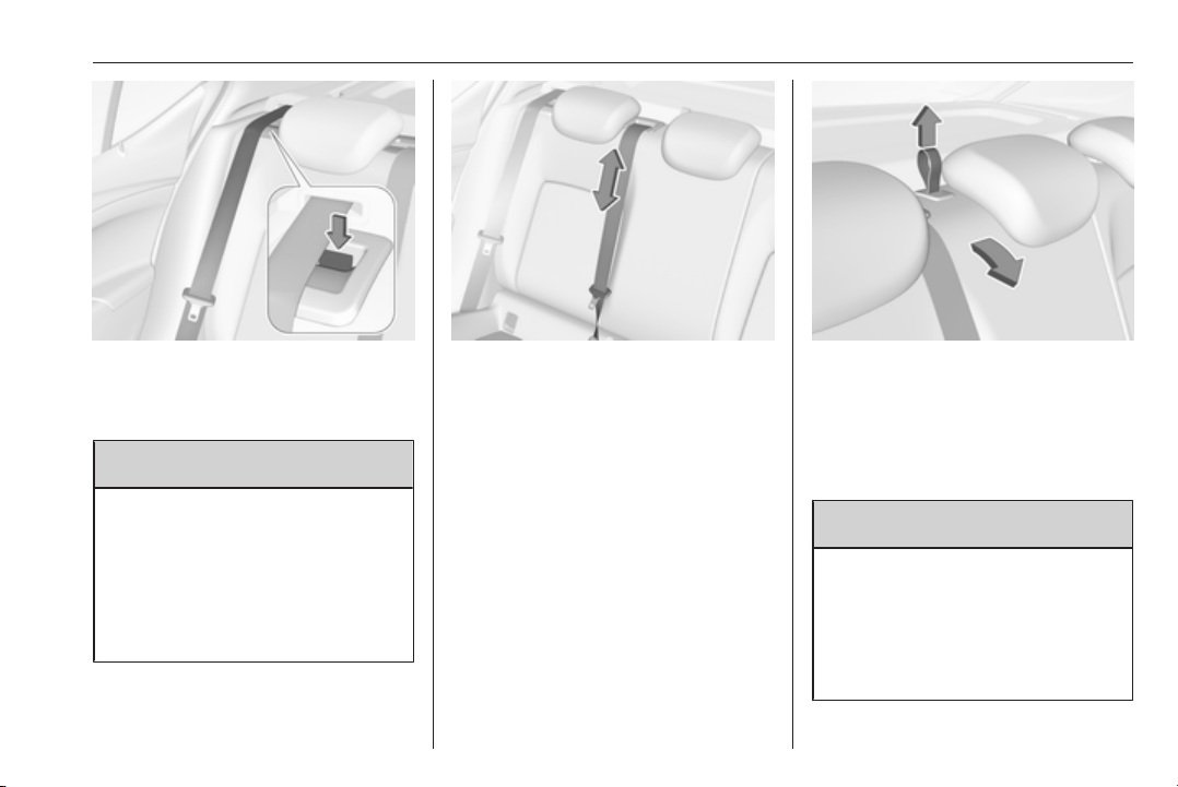
Storage 75
The backrests are properly
engaged when the red mark near
the release lever is no longer
visible.
9 Warning
When folding up, ensure that
backrests are securely locked in
position before driving. Failure to
do so may result in personal injury
or damage to the load or vehicle in
the event of hard braking or a
collision.
The seat belt of the centre seat could
be blocked when the backrest is
folded up too quickly. To unlock the
retractor, push in the seat belt or pull
it out by approx. 20 mm then release.
Load compartment extension
(three-part rear seat backrest), 5door Hatchback
● Fold up the rear armrest.
● Pull the loop and fold down the
backrest of the centre seat.
● Pull the release lever on one or
both outer sides and fold down
the backrests onto the seat
cushion.
9 Warning
Take care when folding down the
right outer seat backrest if the
centre seat backrest is already
folded down. Risk of injury due to
bolt protruding from the inner side
of the backrest.
Page 78
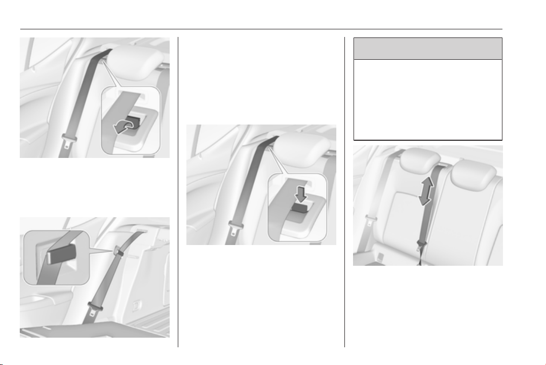
76 Storage
● Guide the seat belts of the outer
seats through side supports to
protect them against damage.
When folding the backrests, pull
the seat belts along with them.
● Take the seat belt out of the seat
backrest guide and put it behind
the retainer as shown in the
illustration.
● To fold up, raise the backrests
and guide them into an upright
position until they engage
audibly.
The backrests are properly
engaged when the red marks on
both sides near the release lever
are no longer visible.
9 Warning
When folding up, ensure that
backrests are securely locked in
position before driving. Failure to
do so may result in personal injury
or damage to the load or vehicle in
the event of hard braking or a
collision.
The seat belt of the centre seat could
be blocked when the backrest is
folded up too quickly. To unlock the
retractor, push in the seat belt or pull
it out by approx. 20 mm then release.
Page 79
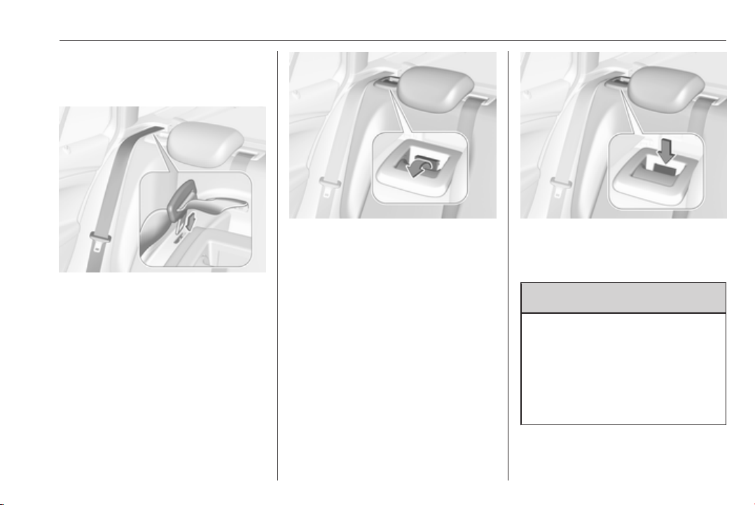
Load compartment extension
(two-part rear seat backrest),
Sports Tourer
Storage 77
● Insert latch plates of the outer
seat belts into side holder to
protect the belts against damage,
see illustration.
● Pull the release lever on one or
both outer sides and fold down
the backrests onto the seat
cushion.
● To fold up, raise the backrests
and guide them into an upright
position until they engage
audibly.
The backrests are properly
engaged when the red marks on
both sides near the release lever
are no longer visible.
9 Warning
When folding up, ensure that
backrests are securely locked in
position before driving. Failure to
do so may result in personal injury
or damage to the load or vehicle in
the event of hard braking or a
collision.
Page 80
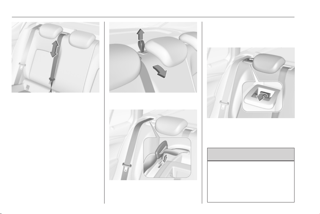
78 Storage
● Insert latch plates of the outer
seat belts into side holder to
protect the belts against damage,
see illustration.
The seat belt of the centre seat could
be blocked when the backrest is
folded up too quickly. To unlock the
retractor, push in the seat belt or pull
it out by approx. 20 mm then release.
Load compartment extension
(three-part rear seat backrest),
Sports Tourer
● Fold up the rear centre armrest.
● Pull the loop and fold down the
backrest of the centre seat.
● Pull the release lever on one or
both outer sides and fold down
the backrests onto the seat
cushion.
9 Warning
Take care when folding down the
right outer seat backrest if the
centre seat backrest is already
folded down. Risk of injury due to
bolt protruding from the inner side
of the backrest.
Page 81
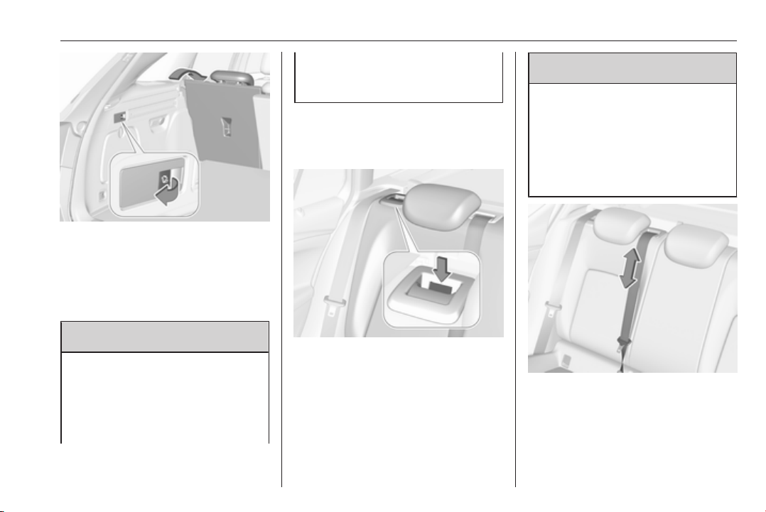
Storage 79
● Alternatively fold seat backrests
from the load compartment: pull
switch on left or right sidewall of
the load compartment to fold the
corresponding part of the rear
seat backrest.
9 Warning
Take care when operating the rear
backrests from the load
compartment. The backrest is
folded with considerable power.
Risk of injury, particularly to
children.
Ensure that nothing is attached to
the rear seats or located on the
seat cushion.
● To fold up, raise the backrests
and guide them into an upright
position until they engage
audibly.
The backrests are properly
engaged when the red marks on
both sides near the release lever
are no longer visible.
9 Warning
When folding up, ensure that
backrests are securely locked in
position before driving. Failure to
do so may result in personal injury
or damage to the load or vehicle in
the event of hard braking or a
collision.
The seat belt of the centre seat could
be blocked when the backrest is
folded up too quickly. To unlock the
retractor, push in the seat belt or pull
it out by approx. 20 mm then release.
Page 82
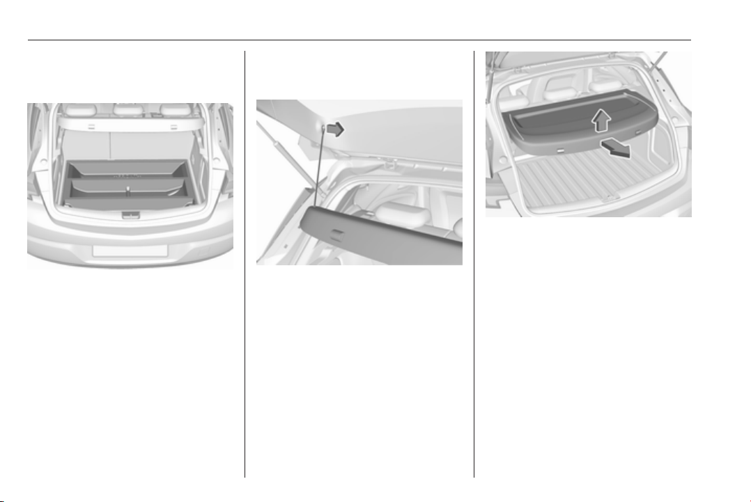
80 Storage
Rear storage
Storage box
A storage box is located in the load
compartment. Remove the cover to
gain access to the storage box. Rear
floor storage cover 3 82.
Load compartment cover
Do not place any objects on the cover.
5-door hatchback
Removing
Unhook retaining strings from
tailgate.
Lift cover at the rear and push it
upwards at the front.
Remove the cover.
Fitting
Engage cover in side guides and fold
downwards. Attach retaining strings
to tailgate.
Sports Tourer
Closing roller blind
Pull the roller blind using the handle
towards the rear and upwards until it
engages in the sideward retainers.
Page 83
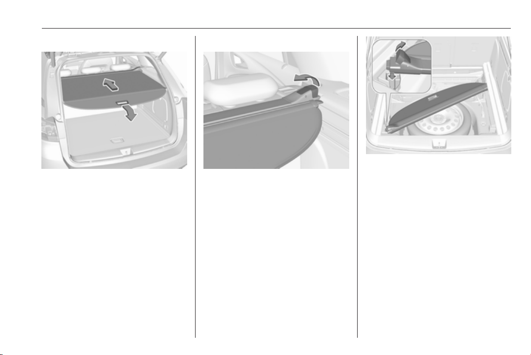
Storage 81
Opening roller blind
Pull the handle at the end of the roller
blind to the rear and downwards. It
rolls up automatically.
Removing roller blind
Open the roller blind.
Pull the release lever on the right side
up and hold it. Lift the roller blind first
on the right side and remove from
retainers.
All engine versions, except CNG: The
removed roller blind can be stored
under the rear floor cover as shown in
the illustration. Insert the left side of
the rolled up cover first in the front
right recess, pull the release lever up
and insert the right side in the front left
recess.
Rear floor storage cover 3 82.
Installing roller blind
Insert the left side of the roller blind in
the recess, then pull the release lever
up and hold and insert the right side
of the roller blind in the recess and
engage.
Page 84
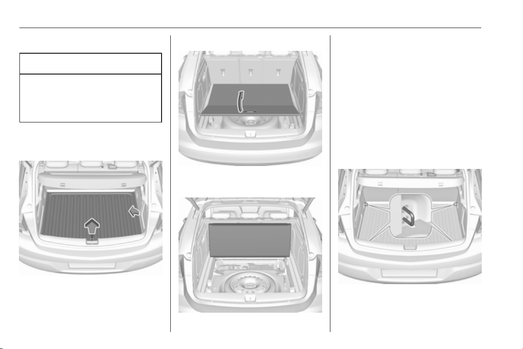
82 Storage
Rear floor storage cover
Caution
Vehicle versions with CNG: Do not
stow any objects in the
compartment beneath the rear
floor cover.
Rear floor cover
5-door Hatchback
The rear floor cover can be removed.
Raise cover at the rear and slightly
rotate at one side before removing.
Sports Tourer
Pull the handle and fold the rear part
of the cover forward.
Set up the folded cover upright behind
the rear seat backrests.
Lashing eyes
The lashing eyes are designed to
secure items against slippage, e.g.
using lashing straps or luggage net.
5-door Hatchback
First remove the rear floor storage
cover to get access to the lashing
eyes.
On vehicles equipped with a spare
wheel, the front lashing eyes are
located at the sidewalls.
Page 85
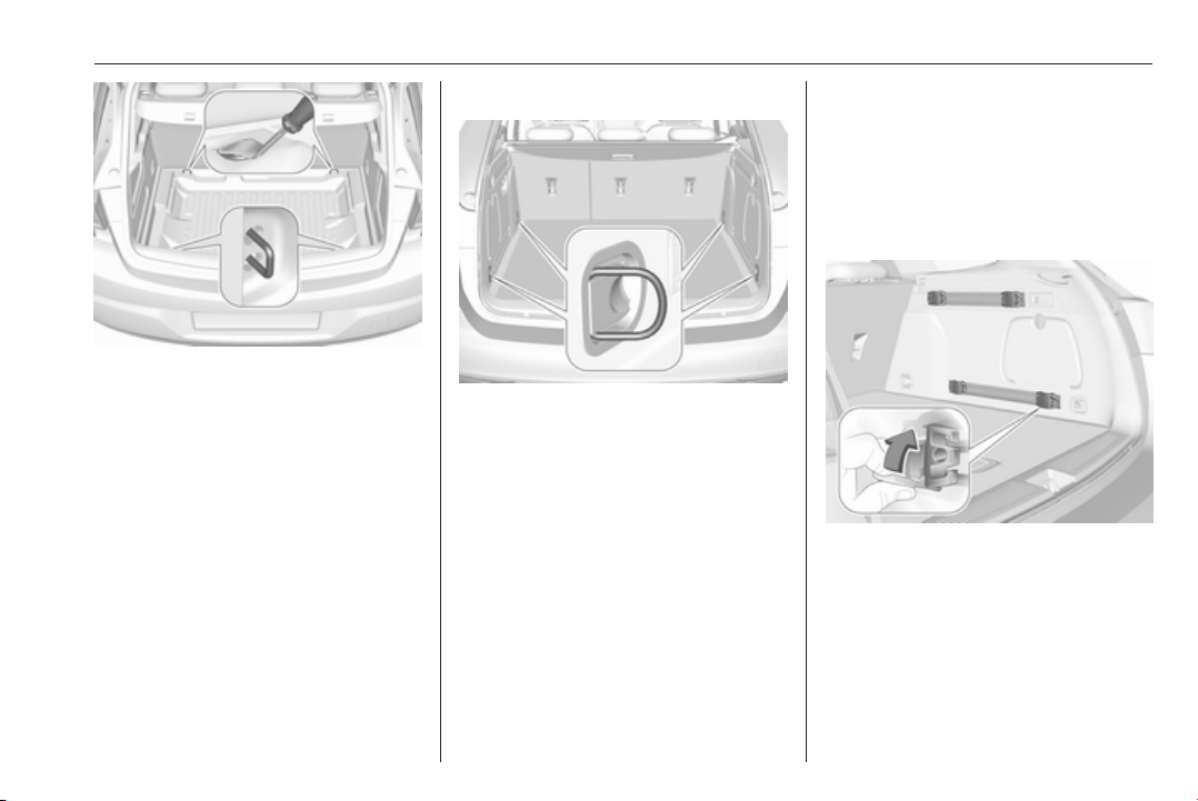
Storage 83
On vehicles equipped with tyre repair
kit, the front lashing eyes are located
underneath the rear floor cover
behind the rear seats. To get access
to the lashing eyes, open the
perforated parts of the cover by using
the screwdriver. Vehicle tools 3 254.
Stick the screwdriver through the
cover as shown in the illustration and
fold up the perforated part of the
cover.
Fold up the lashing eyes by using the
screwdriver.
Sports Tourer
Front and rear lashing eyes are
located at the sidewalls. Fold up the
lashing eyes to use and fold down
when not required.
Cargo management system
The FlexOrganizer is a flexible
system for dividing up the load
compartment.
The system consists of:
● adapters
● mesh pockets
● hooks
● service box
● strap set
The components are fitted in rails on
both side panels using adapters and
hooks.
Installation of adapters in the rails
Fold open the handle plate, insert the
adapter into the upper and lower
groove of the rail and move to the
required position. Turn the handle
plate upwards to lock the adapter. To
remove, turn the handle plate down
and move out of the rail.
Page 86
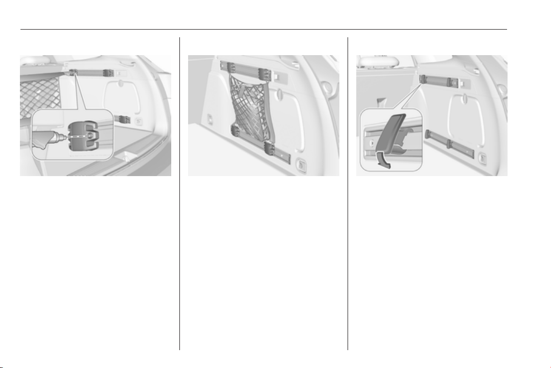
84 Storage
Variable partition net
Insert adapters into the required
position in the rails. Stick together the
halves of the net rods.
To install, push rods together a little
and insert into the relevant openings
in the adapters.
To remove, press the net rods
together and remove from the
adapters.
Net pocket
Insert adapters into the required
position in the rails. The net pocket
can be suspended from the adapters.
Installation of hooks in the rails
Insert the hook in the desired position
first in the upper groove of the rail and
then press in the lower groove. To
remove, first pull out of the upper
groove.
Page 87
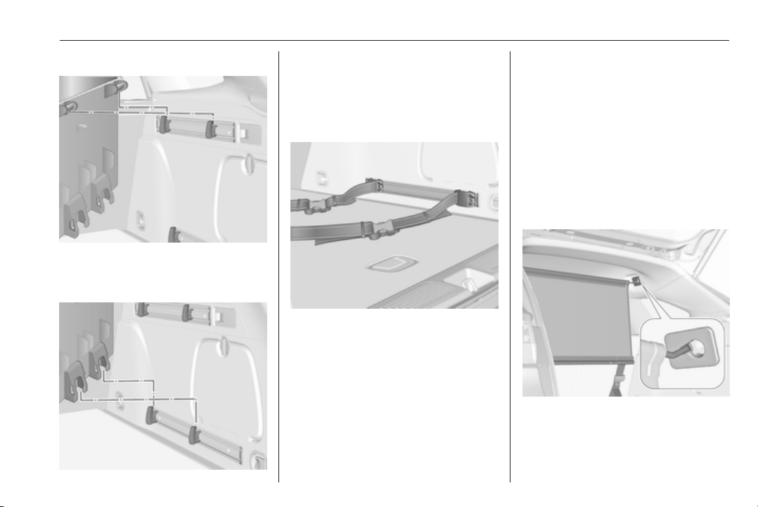
Storage 85
Service box
Install two hooks in the upper rail.
Insert the upper brackets of the box
from above into the hooks.
Alternatively install both hooks in the
lower rail. Plug in the lower brackets
of the box from above into the lower
hooks.
Strap set
Insert the adapters of the strap set in
a rail. Make sure that the belt is not
twisted.
The strap set has two locks to open.
The belt can be tightened.
Safety net
The safety net is available on the
Sports Tourer and can be installed
behind the rear seats or, if the rear
seat backrests are folded, behind the
front seats.
Passengers must not be transported
behind the safety net.
Installation
Behind the rear seats
● There are installation openings
on both sides in the roof frame
above the rear seats: suspend
Page 88
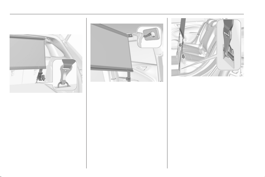
86 Storage
and engage rod of net at one
side, compress rod and suspend
and engage at the other side.
● Attach the hooks of safety net
straps in loops underneath the
rear floor cover behind the rear
seats. To get access to the loops,
open the perforated parts in the
floor cover on both sides by using
the screwdriver and fold up the
loops. Attach the hooks to the
loops.
● Tension both straps by pulling at
the loose end.
● Rear seat backrests must be
raised up.
Behind the front seats
● There are installation openings
on both sides in the roof frame
above the front seats: suspend
and engage rod of net at one
side, compress rod and suspend
and engage at the other side.
● Attach hooks of safety net straps
to loops in the floor in front of the
rear seats. To get access to the
loops, push in the perforated
parts in the floor cover on both
sides. Attach the hooks to the
loops.
● Tension both straps by pulling at
the loose end.
● Push down head restraints and
fold down rear seat backrests
3 74.
Page 89
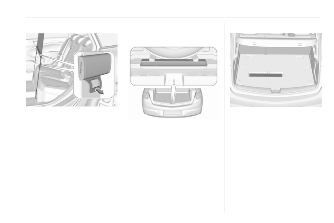
Storage 87
Removal
Pull the flap at the tightener on both
sides to release the straps. Detach
hooks from the eyes.
Unhook the safety net rods from the
brackets in the roof frame.
Roll up the net and secure with a
strap.
Stowing
All engine versions, except CNG: The
removed safety net can be stored
under the rear floor cover 3 82.
Warning triangle
5-door hatchback
Stow the warning triangle in the
recess in front of the tailgate.
5-door hatchback with CNG
Stow the warning triangle in the
recess beneath the rear floor cover.
Page 90
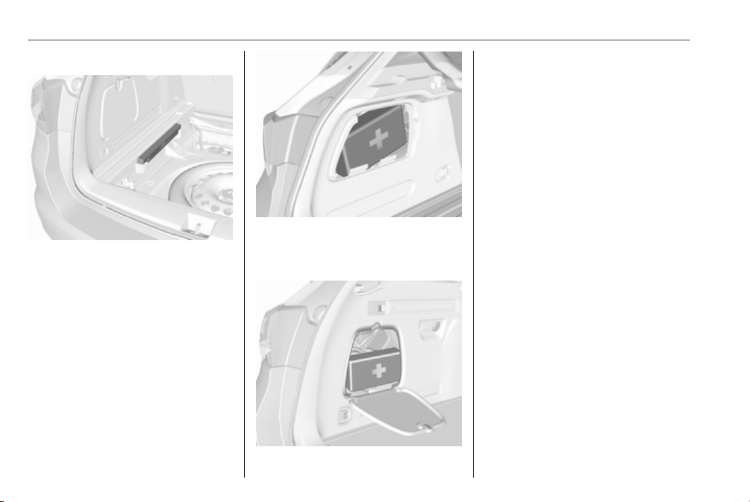
88 Storage
Sports Tourer
Stow the warning triangle in the
recess under the rear floor cover on
the right or left side.
First aid kit
Stow the first aid kit in the
compartment in the left side wall.
To open the cover turn knob.
Illustration shows 5-door Hatchback.
To open the compartment, disengage
cover and open.
Illustration shows Sports Tourer.
Page 91
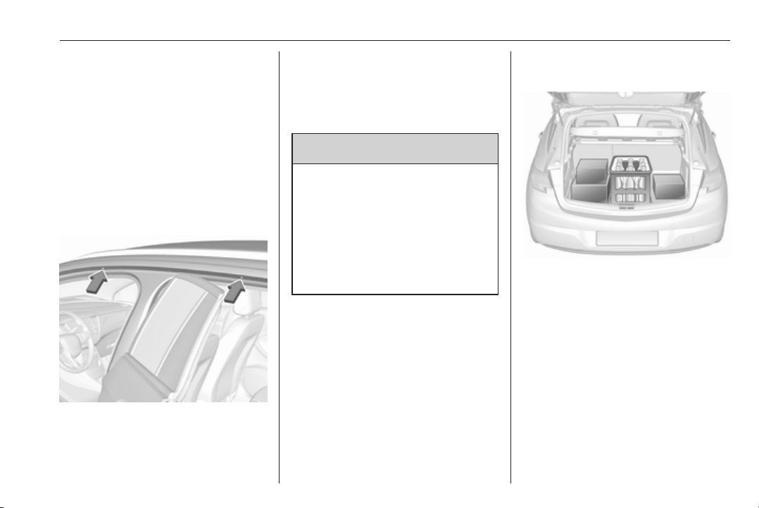
Storage 89
Roof rack system
Roof rack
For safety reasons and to avoid
damage to the roof, the vehicle
approved roof rack system is
recommended. For further
information contact your workshop.
Mounting roof rack
5-door Hatchback, Sports Tourer
Open all doors.
Mounting points are located in each
door frame of the vehicle body.
Fasten the roof rack according to the
installation instructions delivered with
the roof rack.
Remove the roof rack when not in
use.
9 Warning
Sports Tourer
Roof railings are a styling element
only and not designed to carry any
load. Installation of roof racks or
other accessory is not permitted.
Use the designated mounting
points in the door frames
exclusively.
Loading information
● Heavy objects in the load
compartment should be placed
against the seat backrests. Make
sure that the backrests are
securely engaged, i.e. no longer
showing the red markings on the
side near the release lever. If
objects can be stacked, heavier
objects should be placed at the
bottom.
● Prevent sliding of loose objects
by securing them with straps
attached to the lashing eyes
3 82.
Page 92

90 Storage
● Do not allow the load to protrude
above the upper edge of the
backrests.
● Sports Tourer: install safety net
when transporting objects in the
load compartment.
● Do not place any objects on the
load compartment cover or the
instrument panel, and do not
cover the sensor on top of the
instrument panel.
● The load must not obstruct the
operation of the pedals, parking
brake and gear selector lever, or
hinder the freedom of movement
of the driver. Do not place any
unsecured objects in the interior.
● Do not drive with an open load
compartment.
9 Warning
Always make sure that the load in
the vehicle is securely stowed.
Otherwise objects can be thrown
around inside the vehicle and
cause personal injury or damage
to the load or car.
● The payload is the difference
between the permitted gross
vehicle weight (see identification
plate 3 282) and the EC kerb
weight.
To calculate the payload, enter
the data for your vehicle in the
weights table at the front of this
manual.
The EC kerb weight includes
weights for the driver (68 kg),
luggage (7 kg) and all fluids (fuel
tank 90% full).
Optional equipment and
accessories increase the kerb
weight.
● Driving with a roof load increases
the sensitivity of the vehicle to
cross-winds and has a
detrimental effect on vehicle
handling due to the vehicle's
higher centre of gravity.
Distribute the load evenly and
secure it properly with retaining
straps. Adjust the tyre pressure
and vehicle speed according to
the load conditions. Check and
retighten the straps frequently.
Do not drive faster than
120 km/h.
The permissible roof load is
75 kg. The roof load is the
combined weight of the roof rack
and the load.
Page 93

Instruments and controls 91
Instruments and controls
Controls ....................................... 92
Steering wheel adjustment ........ 92
Steering wheel controls ............. 92
Heated steering wheel ............... 93
Horn ........................................... 93
Windscreen wiper and washer ..93
Rear window wiper and
washer ...................................... 95
Outside temperature .................. 96
Clock ......................................... 96
Power outlets ............................. 98
Ashtrays .................................... 99
Warning lights, gauges and indi‐
cators ......................................... 100
Instrument cluster .................... 100
Speedometer ........................... 103
Odometer ................................ 104
Trip odometer .......................... 104
Tachometer ............................. 105
Fuel gauge .............................. 105
Fuel selector ............................ 105
Engine coolant temperature
gauge ..................................... 106
Service display ........................ 107
Control indicators .................... 108
Turn lights ................................ 108
Seat belt reminder ................... 108
Airbag and belt tensioners ....... 109
Airbag deactivation .................. 109
Charging system ..................... 110
Malfunction indicator light ........ 110
Brake and clutch system .........110
Electric parking brake .............. 110
Electric parking brake fault ......110
Antilock brake system (ABS) ...111
Gear shifting ............................ 111
Following distance ................... 111
Lane keep assist ..................... 111
Electronic Stability Control off . 111
Electronic Stability Control and
Traction Control system .........111
Traction Control system off .....112
Preheating ............................... 112
Exhaust filter ............................ 112
AdBlue ..................................... 112
Tyre pressure monitoring
system .................................... 112
Engine oil pressure .................. 112
Low fuel ................................... 113
Immobiliser .............................. 113
Exterior light ............................ 113
High beam ............................... 113
High beam assist ..................... 113
LED headlights ........................ 113
Front fog lights ......................... 114
Rear fog light ........................... 114
Cruise control .......................... 114
Adaptive cruise control ............ 114
Vehicle detected ahead ........... 114
Speed limiter ........................... 114
Traffic sign assistant ................ 114
Door open ................................ 115
Displays ..................................... 115
Driver Information Centre ........ 115
Info Display .............................. 121
Vehicle messages ...................... 123
Warning chimes ....................... 124
Battery voltage ........................ 124
Vehicle personalisation .............. 125
Telematics service ..................... 131
OnStar ..................................... 131
Page 94
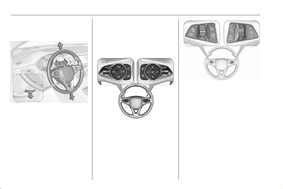
92 Instruments and controls
Controls
Steering wheel adjustment
Unlock lever, adjust steering wheel,
then engage lever and ensure it is
fully locked.
Do not adjust steering wheel unless
vehicle is stationary and steering
wheel lock has been released.
Steering wheel controls
Driver Information Centre, some
driver assistance systems,
Infotainment system and a connected
mobile phone can be operated via the
controls on the steering wheel.
The illustrations show different
versions.
Cruise control and speed limiter are
operated via the controls on the left
side of the steering wheel.
Additionally, forward collision alert
can be set by using the controls on the
left side of the steering wheel.
Infotainment system can be operated
via the controls on the right side of the
steering wheel.
Driver assistance systems 3 184.
Further information is available in the
Infotainment manual.
Page 95
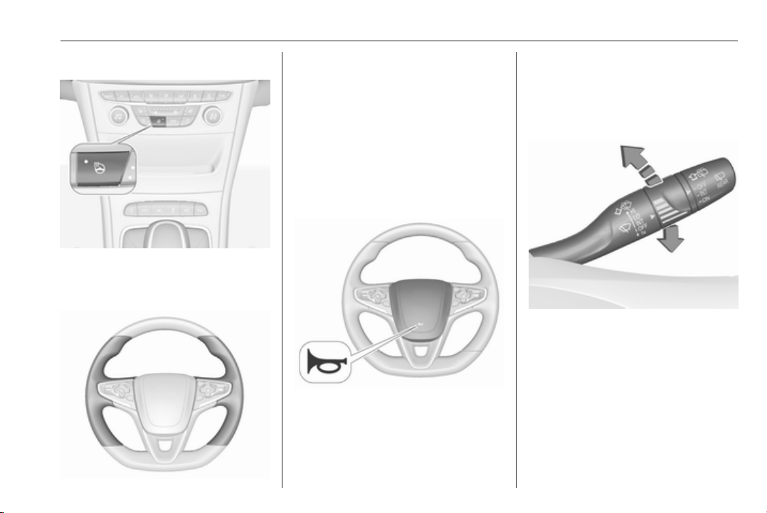
Instruments and controls 93
Heated steering wheel
Activate heating by pressing *.
Activation is indicated by the LED in
the button.
The recommended grip areas of the
steering wheel are heated quicker
and to a higher temperature than the
other areas.
Heating is operational when the
engine is running and during an
Autostop.
Stop-start system 3 162.
Horn
Press
j.
Windscreen wiper and washer
Windscreen wiper with adjustable wiper interval
HI : fast
LO : slow
INT : interval wiping
OFF : off
For a single wipe when the
windscreen wiper is off, press the
lever downwards to position 1x.
Do not use if the windscreen is frozen.
Switch off in car washes.
Page 96
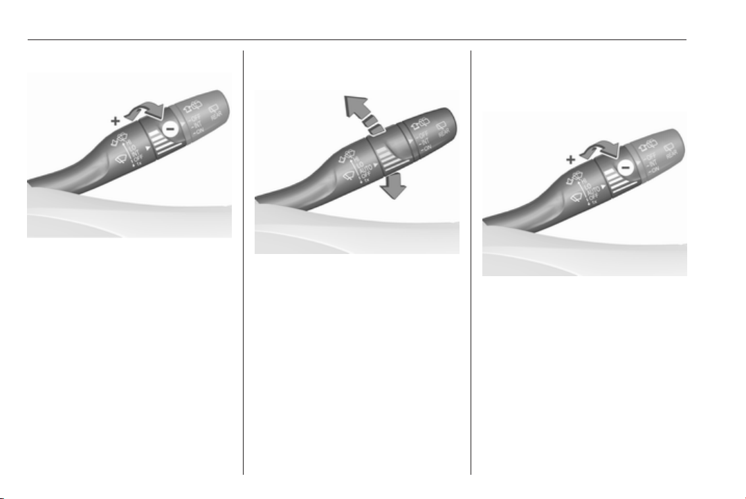
94 Instruments and controls
Adjustable wiper interval
Wiper lever in position INT.
Turn the adjuster wheel to adjust the
wiping frequency.
Windscreen wiper with rain sensor
HI : fast
LO : slow
AUTO : automatic wiping with rain
sensor
OFF : off
In AUTO position, the rain sensor
detects the amount of water on the
windscreen and automatically
regulates the frequency of the
windscreen wiper.
For a single wipe when the
windscreen wiper is off, press the
lever downwards to position 1x.
Do not use if the windscreen is frozen.
Switch off in car washes.
Adjustable sensitivity of the rain sensor
Wiper lever in position AUTO.
Turn the adjuster wheel to adjust the
sensitivity of the rain sensor.
Page 97
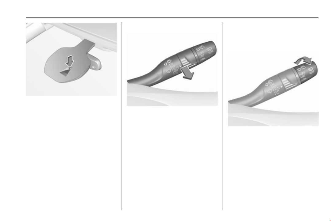
Instruments and controls 95
Keep the sensor free from dust, dirt
and ice.
Rain sensor function can be activated
or deactivated in the Vehicle
personalisation.
Select the relevant setting in Settings,
I Vehicle in the Info-Display.
Info-Display 3 121.
Vehicle personalisation 3 125.
Windscreen washer
Pull lever. Washer fluid is sprayed
onto the windscreen and the wiper
wipes a few times.
Washer fluid 3 234.
Rear window wiper and washer
Rear window wiper
Turn outer cap to activate the rear
window wiper:
OFF : off
INT : intermittent operation
ON : continuous operation
Do not use if the rear window is
frozen.
Switch off in car washes.
Page 98
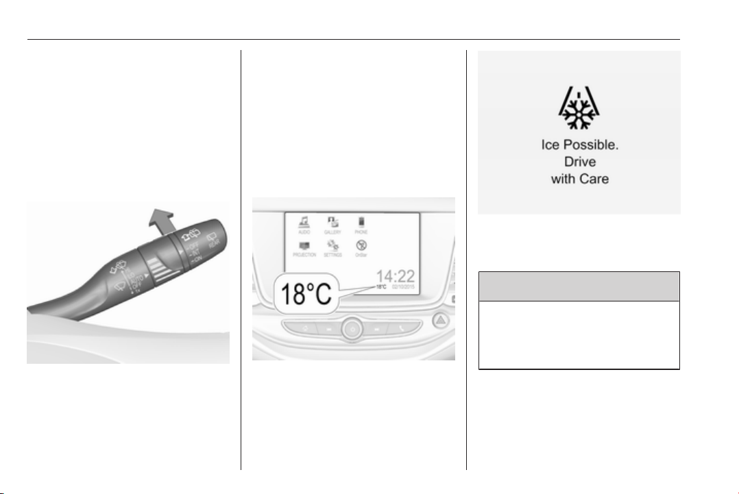
96 Instruments and controls
The rear window wiper comes on
automatically when the windscreen
wiper is switched on and reverse gear
is engaged.
Activation or deactivation of this
function can be changed in the menu
Settings in the Info-Display.
Vehicle personalisation 3 125.
Rear window washer
Push lever.
Washer fluid is sprayed onto the rear
window and the wiper wipes a few
times.
The rear window washer system is
deactivated when the fluid level is
low.
Washer fluid 3 234.
Outside temperature
A drop in temperature is indicated
immediately and a rise in temperature
after a time delay.
Illustration shows an example.
If outside temperature drops to 3 °C,
a warning message is displayed in the
Driver Information Centre.
9 Warning
The road surface may already be
icy even though the display
indicates a few degrees above
0 °C.
Clock
Date and time are shown in the
Info-Display.
Info-Display 3 121.
Page 99
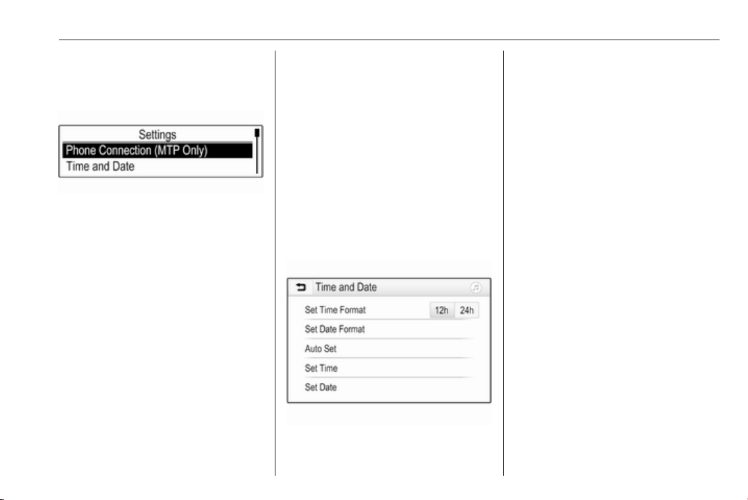
Instruments and controls 97
Graphic-Info-Display
Press MENU to open the respective
audio menu.
Select Time and Date.
Set Time
Select Set Time to enter the
respective submenu.
Select Auto Set at the bottom of the
screen. Activate either On - RDS or
Off (Manual).
If Off (Manual) is selected, adjust
hours and minutes.
Repeatedly select 12-24 HR at the
bottom of the screen to choose a time
mode.
If the 12-hour mode is selected, a
third column for AM and PM selection
is displayed. Select the desired
option.
Set Date
Select Set Date to enter the
respective submenu.
Select Auto Set at the bottom of the
screen. Activate either On - RDS or
Off (Manual).
If Off (Manual) is selected, adjust the
date settings.
7'' Colour-Info-Display
Press ; and then select Settings.
Select Time and Date to display the
respective submenu.
Set Time Format
To select the desired time format,
touch the screen buttons 12 h or 24 h.
Set Date Format
To select the desired date format,
select Set Date Format and choose
between the available options in the
submenu.
Auto Set
To choose whether time and date are
to be set automatically or manually,
select Auto Set.
For time and date to be set
automatically, select On - RDS.
For time and date to be set manually,
select Off - Manual. If Auto Set is set
to Off - Manual, the submenu items
Set Time and Set Date become
available.
Set time and date
To adjust the time and date settings,
select Set Time or Set Date.
Touch + and - to adjust the settings.
Page 100
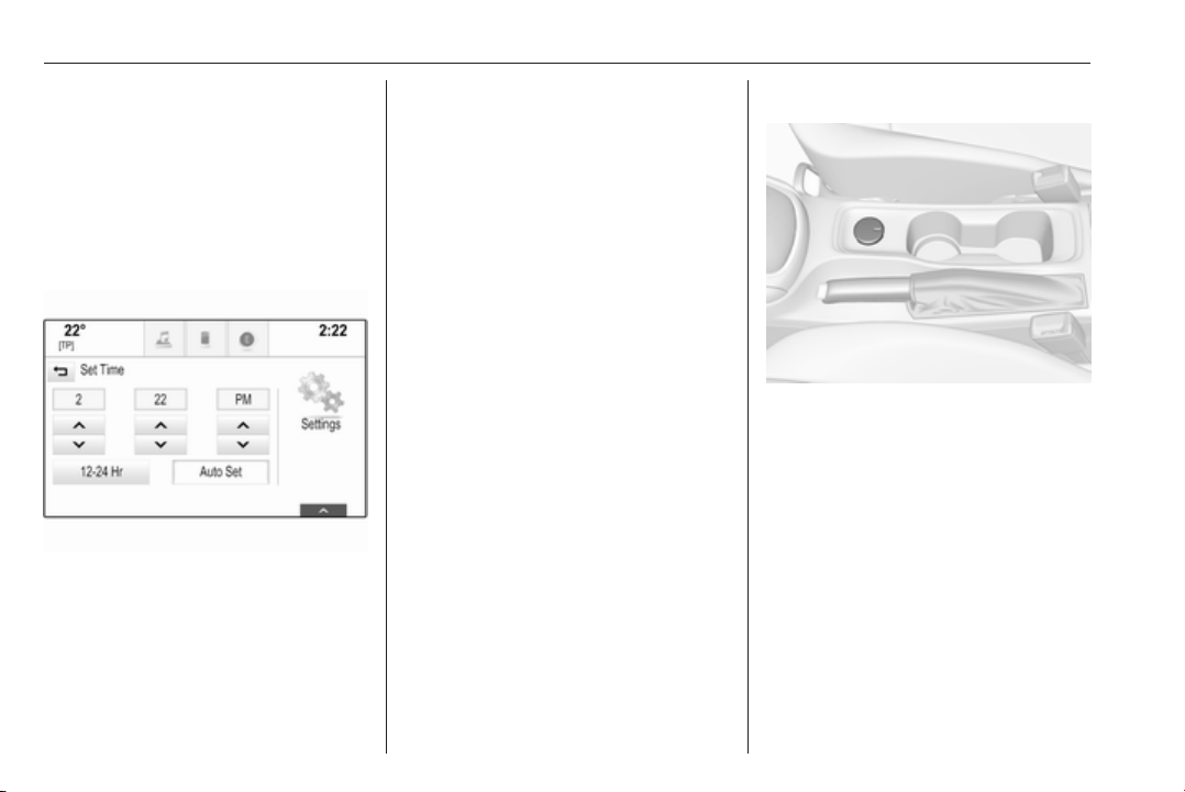
98 Instruments and controls
8'' Colour-Info-Display
Press ; and then select the
Settings icon.
Select Time and Date.
Set time
Select Set Time to enter the
respective submenu.
Select Auto Set at the bottom of the
screen. Activate either On - RDS or
Off - Manual.
If Off - Manual is selected, adjust
hours and minutes by touching n or
o.
Touch 12-24 Hr on the right side of the
screen to select a time mode.
If 12-hour mode is selected, a third
column for AM and PM setting is
displayed. Select the desired option.
Set date
Select Set Date to enter the
respective submenu.
Note
If date information is automatically
provided, this menu item is not
available.
Select Auto Set at the bottom of the
screen. Activate either On - RDS or
Off - Manual.
If Off - Manual is selected, adjust the
date by touching n or o.
Clock display
Select Clock Display to enter the
respective submenu.
To turn off the digital clock display in
the menus, select Off.
Power outlets
A 12 V power outlet is located in the
centre console. With ignition off, this
power outlet is deactivated.
Do not exceed the maximum power
consumption of 120 W.
Electrical accessories that are
connected must comply with the
electromagnetic compatibility
requirements laid down in
DIN VDE 40 839.
Do not connect any current-delivering
accessories, e.g. electrical charging
devices or batteries.
 Loading...