

Page 1

4A
General
Fuel tank capacity . . . . . . . . . . . . . . . . . . . . . . . . . . . . . . . . . . . . . . . . . . 61.0 litres
Fuel octane rating:
Leaded . . . . . . . . . . . . . . . . . . . . . . . . . . . . . . . . . . . . . . . . . . . . . . . . 98 RON (4-star)
Unleaded . . . . . . . . . . . . . . . . . . . . . . . . . . . . . . . . . . . . . . . . . . . . . . 95 RON (Premium)
Carburettor type (all models) . . . . . . . . . . . . . . . . . . . . . . . . . . . . . . . . . Pierburg 2E3
Air cleaner element
Application:
Round type . . . . . . . . . . . . . . . . . . . . . . . . . . . . . . . . . . . . . . . . . . . . . Champion W103
Square type . . . . . . . . . . . . . . . . . . . . . . . . . . . . . . . . . . . . . . . . . . . . . Champion U512
14 NV engine
Idle speed . . . . . . . . . . . . . . . . . . . . . . . . . . . . . . . . . . . . . . . . . . . . . . . . 925 ± 25 rpm
Idle mixture (CO content) . . . . . . . . . . . . . . . . . . . . . . . . . . . . . . . . . . . . 0.5 to 1.5%
Fast idle speed . . . . . . . . . . . . . . . . . . . . . . . . . . . . . . . . . . . . . . . . . . . . 2200 to 2600 rpm
Choke valve gap . . . . . . . . . . . . . . . . . . . . . . . . . . . . . . . . . . . . . . . . . . . 1.5 to 3.5 mm
Choke pull-down gap:
“Small” . . . . . . . . . . . . . . . . . . . . . . . . . . . . . . . . . . . . . . . . . . . . . . . . 1.7 to 2.1 mm
“Large” . . . . . . . . . . . . . . . . . . . . . . . . . . . . . . . . . . . . . . . . . . . . . . . . 2.5 to 2.9 mm
Idle fuel jet . . . . . . . . . . . . . . . . . . . . . . . . . . . . . . . . . . . . . . . . . . . . . . . 45
Idle air bleed . . . . . . . . . . . . . . . . . . . . . . . . . . . . . . . . . . . . . . . . . . . . . . 130
Primary Secondary
Venturi diameter . . . . . . . . . . . . . . . . . . . . . . . . . . . . . . . . . . . . . . . . . . . 20.0 mm 24.0 mm
Main jet . . . . . . . . . . . . . . . . . . . . . . . . . . . . . . . . . . . . . . . . . . . . . . . . . . X95 X110
Chapter 4 Part A:
Fuel and exhaust systems - carburettor models
Accelerator pump - testing, removal and refitting . . . . . . . . . . . . . . .18
Air cleaner inlet air temperature control - description and testing . . . .4
Air cleaner - removal and refitting . . . . . . . . . . . . . . . . . . . . . . . . . . . .3
Automatic choke unit - removal, refitting and adjustment . . . . . . . . .19
Automatic choke vacuum pull-down units - removal, refitting and
adjustment . . . . . . . . . . . . . . . . . . . . . . . . . . . . . . . . . . . . . . . . . . .20
Carburettor - general . . . . . . . . . . . . . . . . . . . . . . . . . . . . . . . . . . . . .12
Carburettor - removal, overhaul and refitting . . . . . . . . . . . . . . . . . . .13
Carburettor filter - removal and refitting . . . . . . . . . . . . . . . . . . . . . . .21
Fuel level sender unit - removal and refitting . . . . . . . . . . . . . . . . . . . .8
Fuel pump - removal and refitting . . . . . . . . . . . . . . . . . . . . . . . . . . . .6
Fuel pump - testing . . . . . . . . . . . . . . . . . . . . . . . . . . . . . . . . . . . . . . .5
Fuel system - precautions . . . . . . . . . . . . . . . . . . . . . . . . . . . . . . . . . .2
Fuel tank - removal, examination and refitting . . . . . . . . . . . . . . . . . . .7
Fuel vapour separator (1.6 and 1.8 litre models) - removal and
refitting . . . . . . . . . . . . . . . . . . . . . . . . . . . . . . . . . . . . . . . . . . . . . . .9
General description . . . . . . . . . . . . . . . . . . . . . . . . . . . . . . . . . . . . . . .1
Idle cut-off solenoid (1.8 litre models) - description and testing . . . .25
Idle speed and mixture - adjustment . . . . . . . . . . . . . . . . . . . . . . . . .14
Idle speed increase valve - testing . . . . . . . . . . . . . . . . . . . . . . . . . . .24
Inlet manifold - removal and refitting . . . . . . . . . . . . . . . . . . . . . . . . .26
Needle valve and float - removal, inspection and refitting . . . . . . . . .15
Power valve diaphragm - removal and refitting . . . . . . . . . . . . . . . . .17
Secondary throttle valve vacuum diaphragm - testing, removal and
refitting . . . . . . . . . . . . . . . . . . . . . . . . . . . . . . . . . . . . . . . . . . . . . .16
Throttle cable - removal, refitting and adjustment . . . . . . . . . . . . . . .11
Throttle pedal - removal and refitting . . . . . . . . . . . . . . . . . . . . . . . . .10
Throttle position sensor (automatic transmission models) - removal
and refitting . . . . . . . . . . . . . . . . . . . . . . . . . . . . . . . . . . . . . . . . . . .23
Throttle valve dashpot (automatic transmission models) -
adjustment . . . . . . . . . . . . . . . . . . . . . . . . . . . . . . . . . . . . . . . . . . .22
4A•1
Specifications
Contents
Easy, suitable for
novice with little
experience
Fairly easy, suitable
for beginner with
some experience
Fairly difficult,
suitable for competent
DIY mechanic
Difficult, suitable for
experienced DIY
mechanic
Very difficult,
suitable for expert DIY
or professional
Degrees of difficulty
5
4
3
2
1
Page 2

16 SV engine
Idle speed
Manual transmission . . . . . . . . . . . . . . . . . . . . . . . . . . . . . . . . . . . . . . 925 ± 25 rpm
Automatic transmission . . . . . . . . . . . . . . . . . . . . . . . . . . . . . . . . . . . 825 ± 25 rpm (in ‘park’ or ‘neutral’)
Idle mixture (CO content) . . . . . . . . . . . . . . . . . . . . . . . . . . . . . . . . . . . . 0.5 to 1.5%
Fast idle speed . . . . . . . . . . . . . . . . . . . . . . . . . . . . . . . . . . . . . . . . . . . . 2000 to 2400 rpm
Choke valve gap . . . . . . . . . . . . . . . . . . . . . . . . . . . . . . . . . . . . . . . . . . . 1.5 to 3.5 mm
Choke pull-down gap:
Up to 1990:
“Small” . . . . . . . . . . . . . . . . . . . . . . . . . . . . . . . . . . . . . . . . . . . . . . . . 1.3 to 1.7 mm
“Large” . . . . . . . . . . . . . . . . . . . . . . . . . . . . . . . . . . . . . . . . . . . . . . . . 1.9 to 2.3 mm
From 1990:
“Small” . . . . . . . . . . . . . . . . . . . . . . . . . . . . . . . . . . . . . . . . . . . . . . . . 1.5 to 1.7 mm
“Large” . . . . . . . . . . . . . . . . . . . . . . . . . . . . . . . . . . . . . . . . . . . . . . . . 2.0 to 2.2 mm
Idle fuel jet . . . . . . . . . . . . . . . . . . . . . . . . . . . . . . . . . . . . . . . . . . . . . . . 45
Idle air bleed . . . . . . . . . . . . . . . . . . . . . . . . . . . . . . . . . . . . . . . . . . . . . . 132.5
Primary Secondary
Venturi diameter . . . . . . . . . . . . . . . . . . . . . . . . . . . . . . . . . . . . . . . . . . . 20.0 mm 24.0 mm
Main jet:
Up to 1990 . . . . . . . . . . . . . . . . . . . . . . . . . . . . . . . . . . . . . . . . . . . . . X95 X105
From 1990 . . . . . . . . . . . . . . . . . . . . . . . . . . . . . . . . . . . . . . . . . . . . . . X92.5 X105
18 SV engine
Idle speed . . . . . . . . . . . . . . . . . . . . . . . . . . . . . . . . . . . . . . . . . . . . . . . . 925 ± 25 rpm
Idle mixture (CO content) . . . . . . . . . . . . . . . . . . . . . . . . . . . . . . . . . . . . 0.5 to 1.5%
Fast idle speed . . . . . . . . . . . . . . . . . . . . . . . . . . . . . . . . . . . . . . . . . . . . 1900 to 2300 rpm
Choke valve gap . . . . . . . . . . . . . . . . . . . . . . . . . . . . . . . . . . . . . . . . . . . 1.5 to 3.5 mm
Choke pull-down gap:
“Small” . . . . . . . . . . . . . . . . . . . . . . . . . . . . . . . . . . . . . . . . . . . . . . . . 2.2 ± 0.2 mm
“Large” . . . . . . . . . . . . . . . . . . . . . . . . . . . . . . . . . . . . . . . . . . . . . . . . 3.3 ± 0.2 mm
Idle fuel jet . . . . . . . . . . . . . . . . . . . . . . . . . . . . . . . . . . . . . . . . . . . . . . . 42.5
Idle air bleed . . . . . . . . . . . . . . . . . . . . . . . . . . . . . . . . . . . . . . . . . . . . . . 132.5
Primary Secondary
Main jet . . . . . . . . . . . . . . . . . . . . . . . . . . . . . . . . . . . . . . . . . . . . . . . . . . 107.5 125
Torque wrench settings Nm lbf ft
Exhaust manifold nuts . . . . . . . . . . . . . . . . . . . . . . . . . . . . . . . . . . . . . . 22 16
Exhaust downpipe-to-manifold bolts . . . . . . . . . . . . . . . . . . . . . . . . . . . 25 18
Exhaust fixings except flexible joint bolts . . . . . . . . . . . . . . . . . . . . . . . . 25 18
Exhaust flexible joint bolts . . . . . . . . . . . . . . . . . . . . . . . . . . . . . . . . . . . 12 9
Fuel pump bolts . . . . . . . . . . . . . . . . . . . . . . . . . . . . . . . . . . . . . . . . . . . 18 13
Fuel tank mounting strap bolts . . . . . . . . . . . . . . . . . . . . . . . . . . . . . . . . 20 15
Inlet manifold nuts . . . . . . . . . . . . . . . . . . . . . . . . . . . . . . . . . . . . . . . . . 22 16
1 General description
The fuel system on all carburettor models
comprises a fuel tank, a fuel pump, a vapour
separator (1.6 and 1.8 litre models only), a
downdraught carburettor, and a thermostatically-controlled air cleaner.
The fuel tank is mounted under the rear of
the vehicle, forward of the rear suspension.
The tank is ventilated to the atmosphere, and
has a simple filler pipe and a fuel gauge
sender unit.
The fuel pump is a mechanical diaphragm
type, actuated by a pushrod bearing on the
camshaft.
The fuel vapour separator is used to
stabilise the fuel supply to the carburettor.
Vapour is purged from the carburettor fuel
supply, thus improving hot starting qualities.
The carburettor is a Pierburg 2E3 type, a full
description of which is given in Section 12.
The air cleaner has a wax or vacuumcontrolled air inlet supplying a blend of hot
and cold air to suit the prevailing engine
operating conditions. A fuller description is
given in Section 4.
All engines available within the Cavalier
range can be operated on unleaded petrol see Chapter 5.
2 Fuel system - precautions
1 Certain adjustment points in the fuel system
are protected by tamperproof caps, plugs or
seals. In some territories, it is an offence to
drive a vehicle with broken or missing
tamperproof seals. Before disturbing a
tamperproof seal, check that no local or
national laws will be broken by doing so, and
fit a new tamperproof seal after adjustment is
complete, where required by law. Do not
break tamperproof seals on a vehicle that is
still under warranty.
2 When working on fuel system components,
scrupulous cleanliness must be observed,
and care must be taken not to introduce any
foreign matter into fuel lines or components.
Carburettors in particular are delicate
instruments, and care should be taken not to
disturb any components unnecessarily.
Before attempting work on a carburettor,
ensure that the relevant spares are available.
Full overhaul procedures for carburettors have
not been given in this Chapter. Complete
stripdown of a carburettor is unlikely to cure a
fault that is not immediately obvious, without
introducing new problems. If persistent
problems are met, it is recommended that the
advice of a Vauxhall dealer or carburettor
specialist is sought. Most dealers will be able
to provide carburettor re-setting and servicing
facilities, and if necessary it should be
possible to buy a reconditioned carburettor.
3 Refer to Chapter 5, for precautions to be
observed when working on vehicles fitted with
an engine management system.
4A•2 Fuel and exhaust systems - carburettor models
Page 3
3 Air cleaner - removal and
refitting
2
Removal
1 Remove the air cleaner element, as
described in Chapter 1.
2 Release the crankcase ventilation hose
from the plastic clip on the left-hand side of
the air cleaner body.
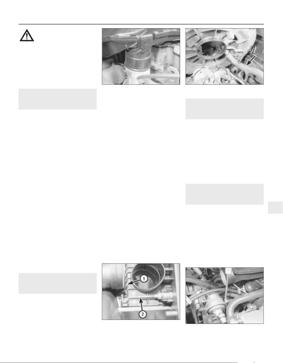
3 Disconnect the inlet duct from the hot air
hose on the exhaust manifold (see
illustration), and lift the air cleaner body from
the carburettor.
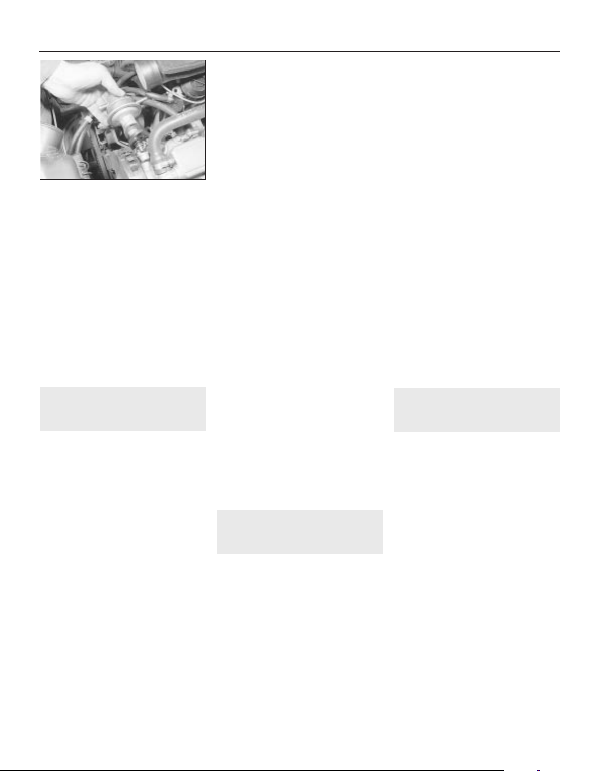
4 With the body tilted to the rear, disconnect
the crankcase ventilation hose from the stub
on the underside of the body (see
illustration). Where applicable, disconnect
the vacuum hose from the air temperature
control flap thermostat.
5 Remove the seal from under the air cleaner
body.
Refitting
6 Check the hot air hose for condition, and
renew it if necessary.
7 Fit a new air cleaner body-to-carburettor
seal.
8 Connect the crankcase ventilation hose to
the stub on the underside of the body, and
connect the vacuum hose for the air
temperature control flap.
9 Locate the body on the carburettor, and at
the same time locate the inlet duct on the hot
air hose on the exhaust manifold.
10 Engage the crankshaft ventilation hose in
the plastic clip.
11 Refit the air cleaner element, referring to
Chapter 1 if necessary.
4 Air cleaner inlet air
temperature control -
description and testing
3
Description
1 The air cleaner is thermostaticallycontrolled, to provide air at the most suitable
temperature for combustion with minimum
exhaust emission levels.
2 The optimum air temperature is achieved
by drawing in cold air from an inlet at the front
of the vehicle, and blending it with hot air
drawn from a shroud on the exhaust manifold.
The proportion of hot and cold air is varied by
the position of a flap valve in the air cleaner
inlet spout, which is controlled by either a
vacuum diaphragm or wax-type unit. The
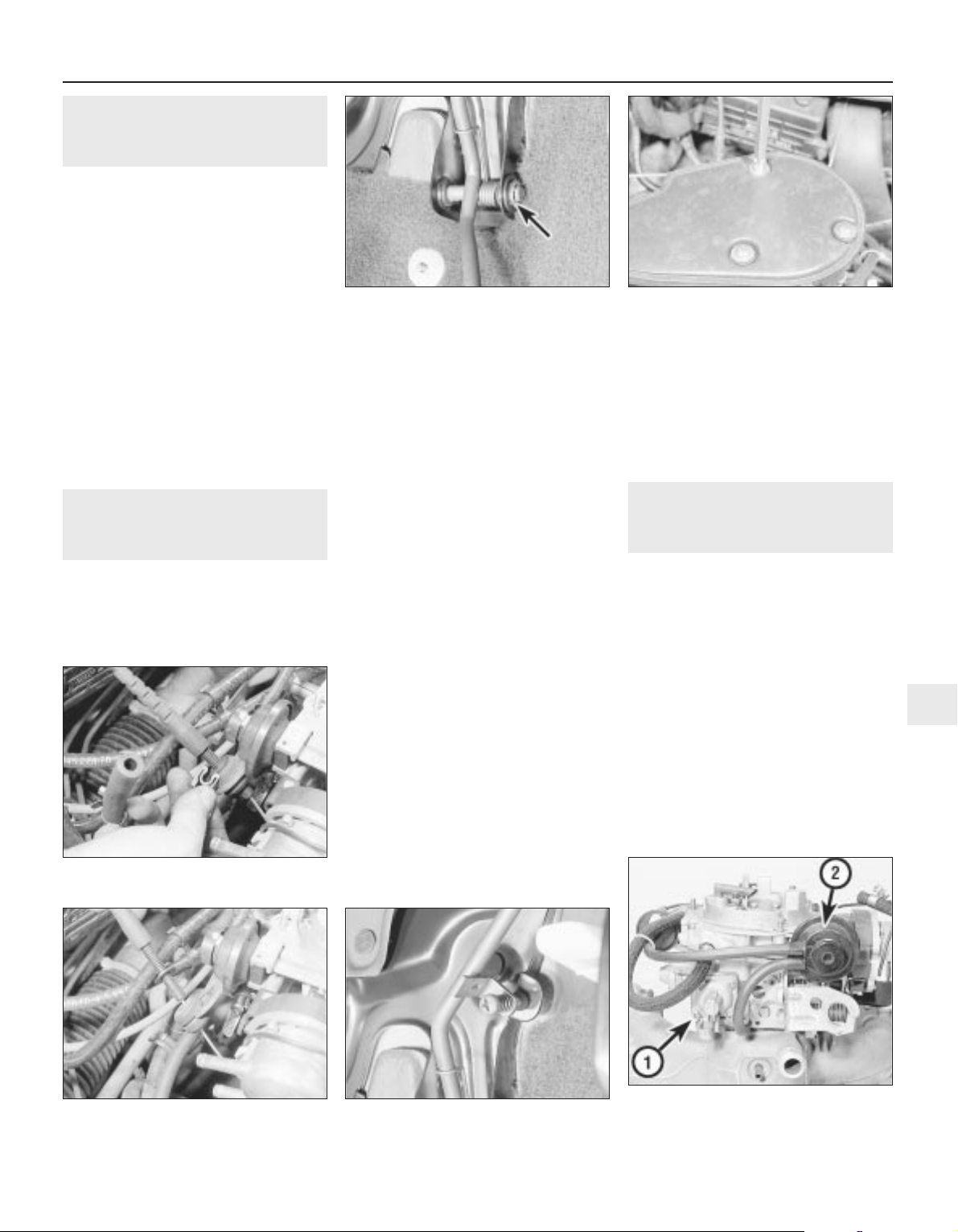
vacuum diaphragm type is regulated by a heat
sensor located within the air cleaner body
(see illustration).
Testing
3 To check the operation of the air
temperature control, the engine must be cold.
First check the position of the flap valve. On
the vacuum type, remove the air cleaner cover
and check that the flap is open to admit only
cold air from outside the car. Then start the
engine and check that the flap now moves to
admit only hot air from the exhaust manifold.
On the wax type, the flap should already be
positioned to admit only hot air from the
exhaust manifold.
4 Temporarily refit the cover on the vacuum
type.
5 Run the engine until it reaches its normal
operating temperature.
6 On the vacuum type, remove the air cleaner
cover and check that the flap is now
positioned to admit only cold air from outside
the car. In cold weather it should be a mixture
of hot and cold air. Refit the cover after
making the check. On the wax type, use a
mirror to check that the flap is positioned in
the same way as given for the vacuum type.
7 If the flap does not function correctly, the
air cleaner casing must be renewed. Note that
the vacuum type thermostat can be renewed
separately if necessary.
5 Fuel pump - testing
2
Note: Refer to Section 2 before proceeding
1 Disconnect the ignition coil LT lead.
2 Place a clean piece of rag under the pump
outlet, then disconnect the pump outlet hose.
Be prepared for fuel spillage, and take
adequate fire precautions.
3 Have an assistant crank the engine on the
starter. Well-defined spurts of fuel must be
ejected from the pump outlet - if not, the
pump is probably faulty (or the tank is empty).
Dispose of the fuel-soaked rag safely.
4 No spare parts are available for the pump,
and if faulty, the unit must be renewed.
6 Fuel pump - removal and
refitting
3
Note: Refer to Section 2 before proceeding
Removal
1 The fuel pump is located at the rear righthand end of the camshaft housing.
2 Disconnect the battery negative lead.
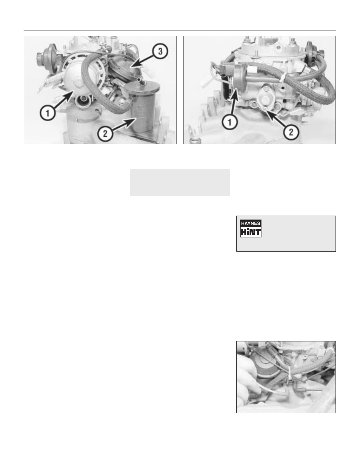
3 Disconnect the fuel hoses from the pump
(see illustration). If necessary, label the
hoses so that they can be reconnected to
their correct locations. Be prepared for fuel
spillage, and take adequate fire precautions.
Plug the open ends of the hoses to prevent
dirt ingress and further fuel spillage.
Fuel and exhaust systems - carburettor models 4A•3
3.4 Disconnecting the crankcase
ventilation hose (arrowed)
6.3 Disconnecting a fuel hose from the
fuel pump - 1.6 litre model
4.2 Air cleaner flap valve operating
mechanism
1 Flap valve 2 Operating rod
3.3 The air cleaner body locates over the
hot air hose
4A
Warning: Many of the
procedures given in this
Chapter involve the
disconnection of fuel pipes and
system components, which may result in
some fuel spillage. Before carrying out
any operation on the fuel system, refer to
the precautions given in the “Safety first!”
Section at the beginning of this manual
and follow them implicitly. Petrol is a
highly dangerous and volatile substance,
and the precautions necessary when
handling it cannot be overstressed.
Page 4
4 Unscrew the two securing bolts, and
withdraw the pump from the camshaft
housing (see illustration).
5 Recover the plastic insulating block.
Refitting
6 Refitting is a reversal of removal, but ensure
that the fuel hoses are reconnected to their
correct locations as noted during removal,
and tighten the securing bolts to the specified
torque.
7 Run the engine and check for leaks on
completion. If leakage is evident, stop the
engine immediately and rectify the problem
without delay. Note that the engine may take
a longer time than usual to start when the
pump has been removed, as the pump refills
with fuel.
7 Fuel tank - removal,
examination and refitting
4
Note: Refer to Section 2 before proceeding
Removal
1 Disconnect the battery negative lead.
2 Siphon out any remaining fuel in the tank
through the filler pipe. Siphon the fuel into a
clean metal container that can be sealed.
3 Chock the front wheels, then jack up the
rear of the vehicle, and support securely on
axle stands (see “Jacking and Vehicle
Support”) placed under the body side
members.
4 Disconnect the exhaust system front
flexible joint. Suspend the front section of the
exhaust system with wire or string from the
underbody.
5 Disconnect the rear section of the exhaust
system from its rubber mountings, and allow it
to rest on the rear suspension torsion beam. It
is advisable to support the rear section of the
exhaust at its front end, with wire or string
from the underbody, to avoid straining the
system.
6 Unclip the handbrake cable from the
bracket on the left-hand fuel tank securing
strap.
7 Disconnect the fuel hoses from the fuel
level sender unit located in the right-hand side
of the fuel tank. Make a note of the hose
positions for use when refitting. Be prepared
for fuel spillage, and take adequate fire
precautions. Plug the open ends of the hoses,
to prevent dirt ingress and further fuel loss.
8 Disconnect the wiring plug from the fuel
level sender unit.
9 Disconnect the filler and vent hoses from
the rear of the fuel tank.
10 Support the weight of the fuel tank on a
jack with an interposed block of wood.
11 Unscrew the securing bolts from the tank
mounting straps, then remove the straps and
lower the tank sufficiently to enable the
disconnection of the remaining vent hose.
12 With the aid of an assistant, withdraw the
tank sideways from the right-hand side of the
vehicle. Note that as the tank is withdrawn,
some residual fuel may be released.
Examination
13 If the tank contains sediment or water, it
may be cleaned out using two or three rinses
with clean fuel. Shake vigorously using
several changes of fuel, but before doing so,
remove the fuel level sender unit, as
described in Section 8. This procedure should
be carried out in a well-ventilated area, and it
is vital to take adequate fire precautions refer to the “Safety first!” Section at the
beginning of this manual for further details.
14 Any repairs to the fuel tank should be
carried out by a professional. Do not under
any circumstances attempt to weld or solder a
fuel tank. Removal of all residual fuel vapour
requires several hours of specialist cleaning.
Refitting
15 Refitting is a reversal of removal, ensuring
that all hoses are reconnected to their correct
locations as noted during removal.
16 On completion, fill the fuel tank, then run
the engine and check for leaks. If leakage is
evident, stop the engine immediately and
rectify the problem without delay. Note that
the engine may take a longer time than usual
to start when the fuel tank has been removed,
as the pump refills with fuel.
8 Fuel level sender unit -
removal and refitting
3
Note: Refer to Section 2 before proceeding
Removal
1 Disconnect the battery negative lead.
2 Siphon out any remaining fuel in the tank
through the filler pipe. Siphon the fuel into a
clear metal container that can be sealed.
3 Chock the front wheels, then jack up the rear
of the vehicle, and support securely on axle
stands (see “Jacking and Vehicle Support”)
placed under the body side members.
4 The sender unit is located in the right-hand
side at the fuel tank.
5 Make alignment marks on the sender unit
and the fuel tank, so that the sender unit can
be refitted in its original position.
6 Disconnect the fuel hoses from the sender
unit. Be prepared for fuel spillage, and take
adequate fire precautions. Plug the open ends
of the hoses, to prevent dirt ingress and
further fuel loss.
7 Disconnect the wiring plug from the fuel
level sender unit.
8 To remove the sender unit, engage a flat
piece of metal as a lever between two of the
slots on the sender unit rim, and turn it anticlockwise.
9 Withdraw the unit carefully, to avoid
bending the float arm.
10 Recover the sealing ring.
Refitting
11 Refitting is a reversal of removal,
remembering the following points.
12 Examine the condition of the sealing ring,
and renew if necessary.
13 Ensure that the marks made on the
sender unit and fuel tank before removal are
aligned.
14 Ensure that the hoses are reconnected to
their correct locations as noted during
removal.
15 On completion, fill the fuel tank, then run
the engine and check for leaks. Also check
that the fuel gauge reads correctly. If leakage
is evident, stop the engine immediately and
rectify the problem without delay. Note that
the engine may take a longer time than usual
to start when the sender unit has been
removed, as the fuel pump refills with fuel.
9 Fuel vapour separator (1.6
and 1.8 litre models) -
removal and refitting
3
Note: Refer to Section 2 before proceeding
Removal
1 The fuel vapour separator is located on a
bracket attached to the side of the
carburettor.
2 Note the locations of the three fuel hoses,
labelling them if necessary for use when
refitting, then disconnect the hoses from the
vapour separator. Be prepared for fuel
spillage, and take adequate fire precautions.
Plug the open ends of the hoses, to prevent
dirt ingress and further fuel spillage.
3 Remove the two securing screws, and lift
the vapour separator from its bracket.
4 Check the body of the separator for cracks
or leaks before refitting, and renew if
necessary.
Refitting
5 Refitting is a reversal of removal, but ensure
that the three fuel hoses are connected to
their correct locations as noted during
removal.
6 Run the engine and check the hose
connections for leaks on completion. If
leakage is evident, stop the engine
immediately and rectify the problem without
delay.
4A•4 Fuel and exhaust systems - carburettor models
6.4 Withdrawing the fuel pump and plastic
insulating block - 1.6 litre model
Page 5
10 Throttle pedal - removal and
refitting
3
Removal
1 Working inside the vehicle, remove the
lower trim panel from the driver’s footwell.
2 Slide the cable retainer from the bracket on
the top of the pedal, and disconnect the cable
end from the pedal.
3 Extract the circlip from the right-hand end
of the pedal pivot shaft, then slide out the
pivot shaft from the left-hand side of the pivot
bracket (see illustration). Recover the pivot
bushes and the pedal return spring.
4 Examine the pivot bushes for wear, and
renew if necessary.
Refitting
5 Refitting is a reversal of removal, but on
completion check the throttle mechanism for
satisfactory operation, and check the throttle
cable adjustment, as described in Section 11.
11 Throttle cable - removal,
refitting and adjustment
3
Removal
1 Remove the air cleaner, on early models.
On later models, disconnect the air trunking
from the air cleaner, then disconnect the
vacuum pipe and breather hose from the air
box. Extract the three securing screws and lift
off the air box, complete with air trunking (see
illustration).
2 Extract the clip from the cable end fitting at
the bracket on the carburettor, then slide the
cable end grommet from the bracket (see
illustrations).
3 Slide the cable end from the throttle valve
lever on the carburettor.
4 Working inside the vehicle, remove the
lower trim panel from the driver’s footwell.
5 Slide the cable retainer from the bracket on
the top of the pedal, and disconnect the cable
end from the pedal.
6 Make a careful note of the cable routing,
then withdraw the cable through the bulkhead
into the engine compartment.
Refitting
7 Refitting is a reversal of removal,
remembering the following points.
8 Ensure that the cable is correctly routed, as
noted before removal.
9 Ensure that the bulkhead grommet is
correctly seated in its hole.
Adjustment
10 On completion, check the throttle
mechanism for satisfactory operation, and if
necessary adjust the cable, as described in
the following paragraphs.
11 Two points of cable adjustment are
provided. A stop screw is located on the
pedal arm to control the fully released position
of the pedal stop (see illustration). A clip is
located on a threaded section of the cable
sheath at the bracket on the carburettor, to
adjust the cable free play.
12 The cable should be adjusted so that
when the throttle pedal is released, there is
very slight free play in the cable at the
carburettor end.
13 Check that when the throttle pedal is fully
depressed, the throttle valve is fully open.
Adjust the position of the clip on the cable
sheath, and the pedal stop screw, to achieve
the desired results.
12 Carburettor - general
1 The Pierburg 2E3 carburettor is of twin-
venturi, fixed-jet sequential throttle type. The
primary throttle valve operates alone except
at high engine speeds and loads, when the
secondary throttle valve is operated, until at
full-throttle, both are fully open. This
arrangement allows good fuel economy
during light acceleration and cruising, but also
gives maximum power at full-throttle. The
secondary throttle valve is vacuum-operated,
according to the vacuum produced in the
primary venturi. The primary throttle barrel
and venturi diameters are smaller than their
secondary counterparts. The carburettor is a
complicated instrument, with various
refinements and sub-systems added to
achieve improved driveability, economy and
exhaust emission levels (see illustrations).
Fuel and exhaust systems - carburettor models 4A•5
11.2A Extract the throttle cable end
clip . . .
12.1A Side view of carburettor, showing
accelerator pump (1) and main choke pull-
down diaphragm unit (2)
11.11 Throttle pedal stop screw11.2B . . .and slide the grommet from the
bracket
11.1 Removing an air box securing screw10.3 Throttle pedal pivot assembly. Circlip
arrowed
4A
Page 6
2 A separate idle system operates
independently from the main jet system,
supplying fuel by way of the mixture control
screw.
3 The main jets are calibrated to suit engine
requirements at mid-range throttle openings.
To provide the necessary fuel enrichment at
full throttle, a vacuum-operated power valve is
used. The valve provides extra fuel under the
low vacuum conditions associated with wide
throttle openings.
4 To provide an enriched mixture during
acceleration, an accelerator pump delivers
extra fuel to the primary main venturi. The
accelerator pump is operated mechanically by
a cam on the throttle linkage.
5 A fully automatic choke is fitted, operated
by a coolant and electrically heated bi-metal
coil. When the engine is cold, the bi-metal coil
is fully wound up, holding the choke plate
(fitted to the primary barrel) closed. As the
engine warms up, the bi-metal coil is heated
and therefore unwinds, progressively opening
the choke plate. A vacuum operated pulldown system is employed, whereby, if the
engine is under choke but is only cruising (i.e.
not under heavy load) the choke plate is
opened against the action of the bi-metal coil.
The pull-down system prevents an over-rich
mixture, which reduces fuel economy and
may cause unnecessary engine wear when
the engine is cold. A secondary pull-down
solenoid is fitted, which operates in
conjunction with the main diaphragm unit to
modify the pull-down characteristics,
improving fuel economy.
6 1.8 litre models are fitted with an idle cut-off
solenoid. This is an electrically operated valve,
which interrupts the idle mixture circuit when
the ignition is switched off, this preventing
engine “run-on”.
13 Carburettor - removal,
overhaul and refitting
3
Note: Refer to Section 2 before proceeding.
New gasket(s) must be used when refitting the
carburettor. A tachometer and an exhaust gas
analyser will be required to check the idle
speed and mixture on completion
Removal
1 Disconnect the battery negative lead.
2 Remove the air cleaner, on early models.
On later models, disconnect the air trunking
from the air cleaner, then disconnect the
vacuum pipe and breather hose from the air
box. Extract the three securing screws and lift
off the air box, complete with air trunking.
3 On 1.4 litre models, disconnect the fuel
supply hose from the carburettor, and on 1.6
and 1.8 litre models, disconnect the fuel
supply and return hoses from the vapour
separator. Be prepared for fuel spillage, and
take adequate fire precautions. Plug the ends
of the hoses, to prevent dirt ingress and
further fuel spillage.
4 Extract the clip from the throttle cable end
fitting at the bracket on the carburettor, then
slide the cable end grommet from the bracket,
and slide the cable end from the throttle valve
lever.
5 Disconnect the coolant hoses from the
automatic choke housing noting their
locations, as an aid to refitting. Be prepared
for coolant spillage, and plug the hoses, or
secure them with their ends facing upwards,
to prevent further coolant loss.
6 Disconnect the vacuum pipes from the front
of the carburettor, noting their locations and
routing for use when refitting (see
illustration).
7 Disconnect the choke heater wire and any
additional wiring.
8 Unscrew the three securing nuts, and
withdraw the carburettor from the inlet
manifold studs.
9 Recover the gasket(s) and insulator block
that fit between the carburettor and the inlet
manifold.
Overhaul
10 With the carburettor removed from the
vehicle, drain the fuel from the float chamber
and vapour separator (where applicable).
Clean the outside of the carburettor, then
remove the top cover (Section 15).
11 Blow through the jets and drillings with
compressed air, or air from a foot pump - do
not probe them with wire. If it is wished to
remove the jets, unscrew them carefully with
well-fitting tools.
12 Remove the fuel filter gauze from the inlet
union, refer to Section 21, for details. Vauxhall
recommend that it is renewed whenever the
carburettor is cleaned.
4A•6 Fuel and exhaust systems - carburettor models
12.1B Side view of carburettor, showing automatic choke
housing (1), vapour separator (2) and secondary throttle valve
vacuum diaphragm (3)
12.1C Side view of carburettor, showing secondary choke pulldown solenoid (1) and power valve (2)
13.6 Disconnecting the air box vacuum
pipe from the carburettor - 1.6 litre model
Aerosol cans of carburettor
cleaner are widely available
and can prove useful in
helping to clean internal
passages of stubborn obstructions.
Page 7
13 Clean any foreign matter from the float
chamber. Renew the float, the float needle
valve and seat if wear is evident, or if the float
is punctured or otherwise damaged. Check
that the needle valve closes completely before
the float reaches the top of its movement. See
Section 15, for details of float level checking.
14 Renew the diaphragms in the part-load
enrichment valve and in the accelerator pump.
If additional pump or valve parts are supplied
in the overhaul kit, renew these parts also.
15 Further dismantling is not recommended.
Pay particular attention to the throttle opening
mechanism arrangement if it is decided to
dismantle it; the interlocking arrangement is
important.
16 Reassemble in the reverse order to
dismantling. Use new gaskets and seals
throughout; lubricate linkages with a smear of
molybdenum based grease.
Refitting
17 Carry out the following procedure before
refitting.
a) Position the fast idle adjustment screw on
the highest step of the fast idle cam.
b) Use a gauge rod or twist drill of the
specified diameter to measure the
opening of the primary throttle valve.
c) Adjust if necessary at the fast idle
adjustment screw.
d) Note that this is a preliminary adjustment;
final adjustment of the fast idle speed
should take place with the engine running.
18 Refitting is a reversal of removal, but
renew the gasket(s).
19 After refitting, carry out the following
checks and adjustments.
20 Check the throttle cable free play and
adjust if necessary, as described in Section 11.
21 Check and if necessary top-up the
coolant level, as described in Chapter 3.
22 Check and if necessary adjust the idle
speed and mixture, as described in Section 14.
14 Idle speed and mixture -
adjustment
3
Note: Refer to Section 2 before proceeding.
To carry out the adjustments, an accurate
tachometer and an exhaust gas analyser (CO
meter) will be required
1 To check the idle speed and mixture
adjustment, the following conditions must be
met:
a) The engine must be at normal operating
temperature
b) All electrical consumers (cooling fan,
heater blower, headlamps, etc.) must be
switched off
c) The ignition timing and spark plug gaps
must be correctly adjusted - see Chapters
1 and 5
d) The throttle cable free play must be
correctly adjusted - see Section 11
e) The air inlet trunking must be free from
leaks, and the air filter must be clean
f) On automatic models, always select
position, “P”.
2 Connect a tachometer and an exhaust gas
analyser to the vehicle, according to the
equipment manufacturer’s instructions.
3 Start the engine, and run it at 2000 rpm for
approximately 30 seconds, then allow it to
idle. If the idle speed is outside the specified
limits, adjust by means of the throttle stop
screw (see illustration).
4 When the idle speed is correct, check the
CO level in the exhaust gas. If it is outside the
specified limits, adjust by means of the idle
mixture adjustment screw. In production, the
screw is covered by a tamperproof plug;
ensure that no local or national laws are being
broken before removing the plug (see
illustration).
5 On automatic models, when position “D” is
selected (all electrical systems switched off),
the idle speed should not drop perceptibly. If
it does, the vehicle should be taken to a
Vauxhall dealer for the idle-up system to be
checked using special Vauxhall test
equipment.
6 With the idle mixture correct, readjust the
idle speed if necessary.
7 If the cooling fan cuts in during the
adjustment procedure, stop the adjustments,
and continue when the cooling fan stops.
8 When both idle speed and mixture are
correctly set, stop the engine and disconnect
the test equipment.
9 Fit a new tamperproof plug to the idle
mixture adjustment screw, where this is
required by law.
15 Needle valve and float -
removal, inspection and
refitting
4
Note: Refer to Section 2 before proceeding. A
new carburettor top cover gasket must be
used on reassembly. A tachometer and an
exhaust gas analyser will be required to check
the idle speed and mixture on completion
Removal
1 Disconnect the battery negative lead.
2 Remove the round air cleaner, on
applicable models. On other models,
disconnect the air trunking from the air
cleaner, then disconnect the vacuum pipe and
breather hose from the air box. Extract the
three securing screws and lift off the air box,
complete with air trunking.
3 Thoroughly clean all external dirt from the
carburettor.
4 Disconnect the fuel supply hose at the
carburettor. Be prepared for fuel spillage, and
take adequate fire precautions. Plug the end
of the hose, to prevent dirt ingress and further
fuel spillage.
5 Identify the automatic choke coolant hose
locations as an aid to refitting, then
disconnect the hoses. Be prepared for
coolant spillage, and either plug the hoses, or
secure them with their ends facing upwards,
to prevent further coolant loss.
6 Disconnect the choke heater wiring plug.
7 Disconnect the lower vacuum hoses from
the choke pull-down unit.
8 Remove the four carburettor top cover
securing screws, noting their locations, as two
lengths of screw are used (see illustration).
9 Lift off the top cover and recover the
gasket.
Inspection
10 Hold the cover vertically, so that the float
is hanging from its pivot. Then tilt the cover
until the float needle valve is just closed - the
needle spring must not be compressed by the
weight of the float.
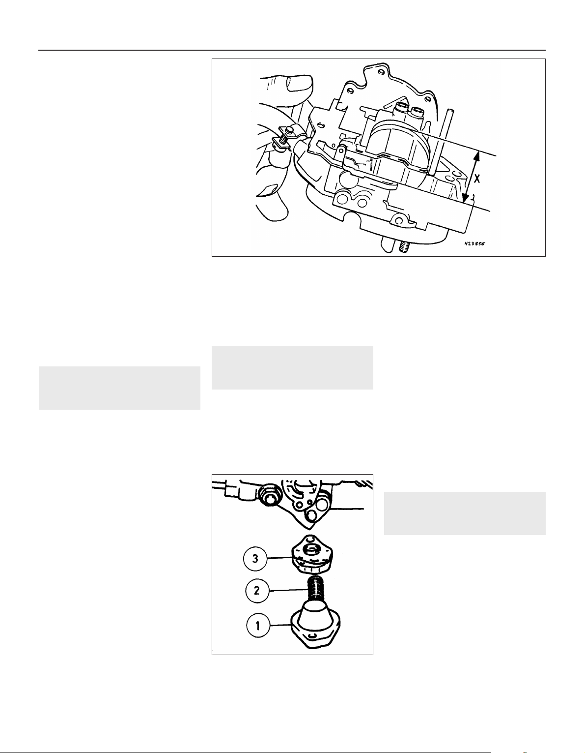
11 Measure the distance, dimension x (see
illustration), from the bottom of the float to
the gasket surface on the top cover’s
Fuel and exhaust systems - carburettor models 4A•7
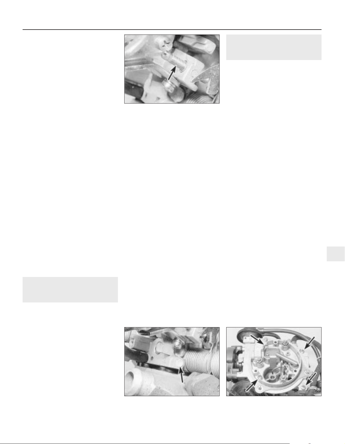
15.8 Carburettor top cover securing
screws (arrowed)
14.4 Tamperproof plug (arrowed) covering
idle mixture adjustment screw
14.3 Carburettor idle speed adjustment
(throttle stop) screw (arrowed)
4A
Page 8
underside. If the distance measured exceeds,
or is less than, that specified, the float weight
is incorrect and the float must be renewed.
12 When the float level is known to be
correct, reassemble the carburettor, using a
new top cover gasket. Check the idle speed
and mixture settings as described in Section
14.
13 Using a pin punch, tap the float retaining
pin from the base of the top cover, and lift out
the float and needle valve.
14 Inspect the components for damage, and
renew as necessary. Check the needle valve
for wear, and check the float for leaks by
shaking it to see if it contains petrol.
15 Clean the mating faces of the carburettor
body and top cover.
Refitting
16 Refitting is a reversal of removal,
remembering the following points.
17 After refitting, check the float and needle
valve for full and free movement.
18 Use a new gasket between the top cover
and the carburettor body.
19 Ensure that all hoses, pipes and wires are
correctly reconnected.
20 On completion, check and if necessary
top-up the coolant level, as described in
Chapter 3, and check and if necessary adjust
the idle speed and mixture, as described in
Section 14.
16 Secondary throttle valve
vacuum diaphragm - testing,
removal and refitting
3
Note: The diaphragm unit must be renewed in
its entirety, as no spares are available
Testing
1 If a vacuum source incorporating a gauge is
available, apply approximately 300 mbars (9 in
Hg) to the diaphragm unit, at the hose nearest
the carburettor body. Close off the vacuum
source, and check that the vacuum is held. If
there is a leak, rectify or renew the leaking
component. Alternately, testing of a suspect
vacuum unit must be by the substitution of a
known good item.
Removal
2 Remove the air cleaner, on early models.
On later models, disconnect the air trunking
from the air cleaner, then disconnect the
vacuum pipe air breather hose from the air
box. Extract the three securing screws and lift
off the air box, complete with air trunking.
3 Disconnect the vacuum pipe from the
diaphragm unit.
4 Prise the diaphragm operating rod balljoint
from the secondary throttle valve linkage.
5 On 1.6 and 1.8 litre models, remove the two
securing screws and lift the vapour separator
from the bracket. Move the vapour separator
to one side, taking care not to strain the fuel
hoses.
6 Remove the three securing screws, and
withdraw the diaphragm unit complete with its
bracket from the carburettor body.
Refitting
7 Refitting is a reversal of removal.
17 Power valve diaphragm -
removal and refitting
3
Note: Refer to Section 2 before proceeding
Removal
1 Disconnect the battery negative lead.
2 Remove the air cleaner, on early models.
On later models, disconnect the air trunking
from the air cleaner, then disconnect the
vacuum pipe and breather hose from the air
box. Extract the three securing screws and lift
off the air box, complete with air trunking.
3 Thoroughly clean all external dirt from the
area around the power valve housing.
4 Remove the two securing screws, and lift
off the power valve cover, spring, and
diaphragm assembly.
Refitting
5 Clean the mating faces of the cover and
housing.
6 Locate the spring on the cover and
diaphragm assembly, ensuring that it is
correctly seated, then press the diaphragm
assembly and cover together. Note that the
vacuum hole in the diaphragm must align with
the corresponding holes in the housing flange
and cover.
7 Further refitting is a reversal of removal, but
ensure that the diaphragm is correctly seated
(see illustration).
18 Accelerator pump - testing,
removal and refitting
3
Note: Refer to Section 2 before proceeding
Testing
1 It will be necessary to feed the float
chamber with fuel from a small reservoir
during this test.
2 Position the primary barrel over an accurate
measuring glass. Fully open and close the
throttle ten times, taking approximately one
second for each opening, and pausing for
three seconds after each return stroke. Make
sure that the fast idle cam is not restricting
throttle travel at either end.
3 Measure the quantity of fuel delivered, and
compare this with the specified value.
4A•8 Fuel and exhaust systems - carburettor models
15.11 Measuring the float level “X”
17.7 Carburettor power valve components
1 Cover
2 Spring
3 Diaphragm
assembly
Page 9
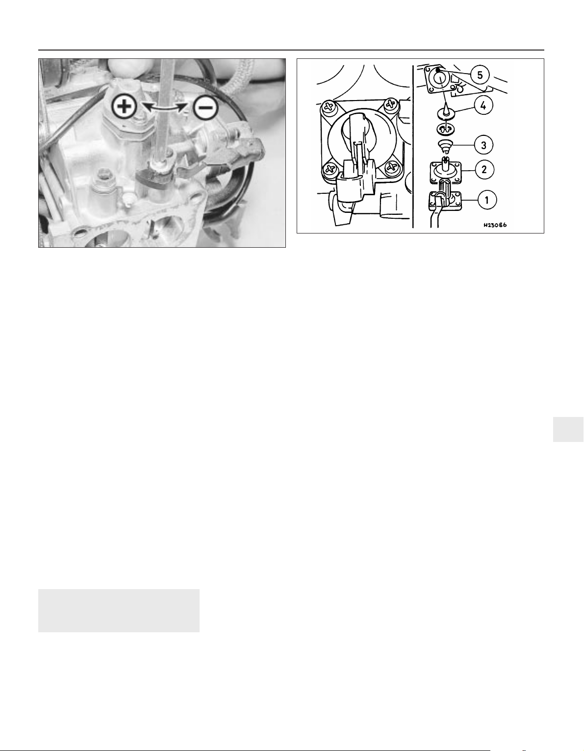
4 If adjustment is necessary, release the
clamp screw and turn the cam plate in the
desired direction. Tighten the clamp screw,
and recheck the pump delivery (see
illustration).
Removal
5 Proceed as described in Section 17,
paragraphs 1 and 2.
6 Thoroughly clean all external dirt from the
area around the accelerator pump housing.
7 Remove the four securing screws and lift off
the accelerator pump cover. Recover the
diaphragm, spring, valve retainer and valve.
Note the orientation of the valve retainer.
Refitting
8 Clean the mating faces of the cover and
housing.
9 Check the condition of the valve, and renew
if necessary.
10 Begin refitting by locating the valve, valve
retainer and spring in the housing. Note that
the valve retainer can only be fitted in one
position. The larger diameter of the spring
should rest against the valve retainer.
11 Locate the diaphragm on the housing,
ensuring that the spring is correctly seated,
and refit the cover. Tighten the cover securing
screws progressively to avoid distorting the
diaphragm (see illustration).
12 Further refitting is a reversal of removal.
19 Automatic choke unit -
removal, refitting and
adjustment
3
Note: Refer to Section 2 before proceeding. A
tachometer and an exhaust gas analyser will
be required to check the idle speed and
mixture on completion. If the coolant housing
is removed, new O-rings will be required for
refitting
Removal
1 Proceed as described in Section 17,
paragraphs 1 and 2.
2 Note the position of the bi-metal housing
alignment marks as an aid to refitting, if
necessary making additional marks for clarity,
then remove the three securing screws and lift
off the bi-metal housing. Place the housing to
one side, taking care not to strain the coolant
hoses or electric choke heater wiring.
3 Remove the three screws securing the
choke housing to the carburettor body, and
withdraw the choke assembly, taking care not
to bend the choke operating rod.
4 If it is necessary to remove the bi-metal
housing for renewal, continue as follows;
otherwise go on to paragraph 8.
5 Identify the automatic choke coolant hose
locations as an aid to refitting, then
disconnect the hoses. Be prepared for
coolant spillage, and either plug the hoses, or
secure them with their ends facing upwards,
to prevent further loss of coolant.
6 Disconnect the wiring from the electric
choke heater, and withdraw the bi-metal
housing.
7 The coolant housing can be separated from
the bi-metal housing by unscrewing the
central securing bolt. Recover the O-rings
from under the bolt head, and from the rim of
the coolant housing.
Refitting
8 Begin refitting by locating the choke
assembly on the carburettor body, ensuring
that the lever on the choke assembly engages
with the choke operating rod. Tighten the
three securing screws.
9 Check and if necessary adjust the choke
valve gap and the fast idle cam position, as
described in paragraphs 15 to 19, of this
Section.
10 Connect the bi-metal spring to the choke
lever, position the bi-metal housing on the
choke housing, and loosely fit the securing
screws. Align the marks on the bi-metal
housing and the choke housing as noted
during removal, then tighten the securing
screws.
11 Where applicable, refit the coolant
housing to the bi-metal housing, using new Orings if necessary, and reconnect the coolant
hoses and electric choke heater wiring.
12 Further refitting is a reversal of removal,
remembering the following points.
13 If the coolant hoses have been
disconnected, check the coolant level, as
described in Chapter 3.
14 Check and if necessary adjust the fast idle
speed, as described in paragraphs 25 to 34,
of this Section.
Adjustment
Choke valve gap
15 With the bi-metal housing removed as
described in paragraphs 2 to 4, of this
Section, continue as follows.
16 Press the choke operating lever fully
clockwise, and retain it in position with a
rubber band.
17 Move the throttle lever to the fully open
position, and measure the choke valve gap
between the lower side of the choke plate and
the wall of the primary barrel. Check that the
gap is as given in the Specifications.
18 If necessary, adjust the choke valve gap
by bending the “adjuster segment (2)” If the
gap is too small, enlarge gap “B”, by levering
with a screwdriver. If the gap is too large,
decrease gap “B” using a pair of pliers (see
illustration).
19 If no further adjustments are to be carried
out, refit the bi-metal housing, as described in
paragraphs 10 to 14, of this Section.
Fuel and exhaust systems - carburettor models 4A•9
18.11 Carburettor accelerator pump components
1 Cover with operating lever
2 Diaphragm
3 Spring
4 Valve
5 Air passage
18.4 Accelerator pump delivery adjustment: “+” to
increase, “-” to reduce
4A
Page 10
Fast idle cam position
20 With the bi-metal housing removed, and
the choke valve gap “B”, correctly set,
continue as follows.
21 Open the throttle valve, then close the
choke valve using light finger pressure on the
choke drive lever (see illustration). Close the
throttle valve.
22 Check that the fast idle speed adjustment
screw is resting against the stop on the
second highest step of the fast idle cam.
23 If adjustment is required, first check that
the choke return spring is correctly
positioned, then adjust by bending the
adjustment lever.
24 Refit the bi-metal housing, as described in
paragraphs 10 to 14 of this Section.
Fast idle speed
Note: To carry out the adjustment, an
accurate tachometer and an exhaust gas
analyser (CO meter) will be required
25 Check the idle speed and mixture, as
described in Section 14. The idle speed must
be correct before attempting to check or
adjust the fast idle speed.
26 With the engine at normal operating
temperature, and a tachometer connected
according to the equipment manufacturer’s
instructions, continue as follows.
27 Position the fast idle speed adjustment
screw on the second highest step of the fast
idle cam (see illustration).
28 Start the engine without touching the
throttle pedal, and check that the fast idle
speed is as specified. If adjustment is
required, stop the engine and continue as
follows.
29 Remove the tamperproof cap from the
fast idle speed adjustment screw, ensure that
no local or national laws are being broken by
doing so (see illustration).
30 Ensure that the adjustment screw is still
resting on the second highest step of the fast
idle cam, then start the engine, again without
touching the throttle pedal.
31 Turn the adjustment screw using a
screwdriver, until the specified fast idle speed
is obtained.
32 If the cooling fan cuts in during the
adjustment procedure, stop the adjustments,
and continue when the cooling fan stops.
33 On completion of adjustment, stop the
engine and disconnect the tachometer.
34 Fit a new tamperproof cap to the fast idle
speed adjustment screw, where this is
required by law.
20 Automatic choke vacuum
pull-down units - removal,
refitting and adjustment
3
Main diaphragm unit
Note: Refer to Section 2 before proceeding. A
new star clip must be used when refitting the
diaphragm unit. Test vacuum units as
described in Section 16, paragraph 1.
Removal
1 Proceed as described in Section 17,
paragraphs 1 and 2.
2 Disconnect the diaphragm unit vacuum
pipes.
3 Using a pin punch, tap out the roll pin
securing the diaphragm unit to the carburettor
top cover.
4 Note the position of the bi-metal housing
alignment marks as an aid to refitting, if
necessary making additional marks for clarity,
then remove the three securing screws, and
lift off the bi-metal housing. Place the housing
to one side, taking care not to strain the
coolant hoses or electric choke heater wiring.
4A•10 Fuel and exhaust systems - carburettor models
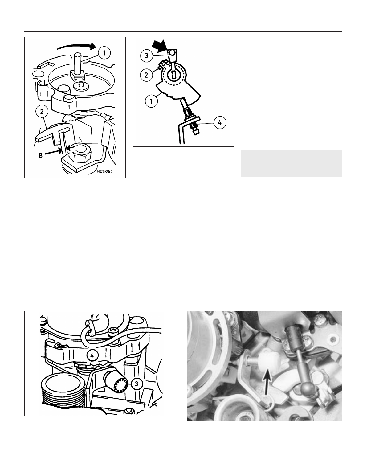
19.18 Choke valve gap adjustment
1 Choke operating lever
2 Adjuster segment
B Choke valve gap
19.21 Fast idle cam adjustment
1 Fast idle cam
2 Adjustment lever
3 Choke drive lever
4 Fast idle speed adjustment screw
19.29 Tamperproof cap (arrowed) fast idle speed adjustment
screw
19.27 Fast idle speed adjustment
3 Fast idle speed adjustment screw
4 Screw positioned on second highest step of cam
Page 11
5 Remove the three screws securing the
choke assembly to the carburettor body.
Allow the choke assembly to drop down, but
do not disconnect the choke linkage.
6 Remove the star clip that secures the
diaphragm unit to the carburettor top cover,
and withdraw the diaphragm unit.
Refitting
7 Refitting is a reversal of removal, but use a
new star clip to secure the diaphragm unit to
the carburettor top cover. Before refitting the
air box to the top of the carburettor, check
and if necessary adjust the choke pull-down,
as follows.
Vacuum pull-down
Adjustment
8 With the air cleaner or air box removed from
the top of the carburettor, as described in
Section 17, paragraph 2, continue as follows.
9 Note the position of the bi-metal housing
alignment marks as an aid to refitting, if
necessary making additional marks for clarity,
then remove the three securing screws, and
lift off the bi-metal housing. Place the housing
to one side, taking care not to strain the
coolant hoses or electric choke heater wiring.
10 Position the fast idle speed adjustment
screw on the highest step of the fast idle cam,
and check that the choke valve is closed.
11 Move the pull-down arm towards the
diaphragm unit by pushing on the adjustment
screw until resistance is felt. Hold the arm in
this position.
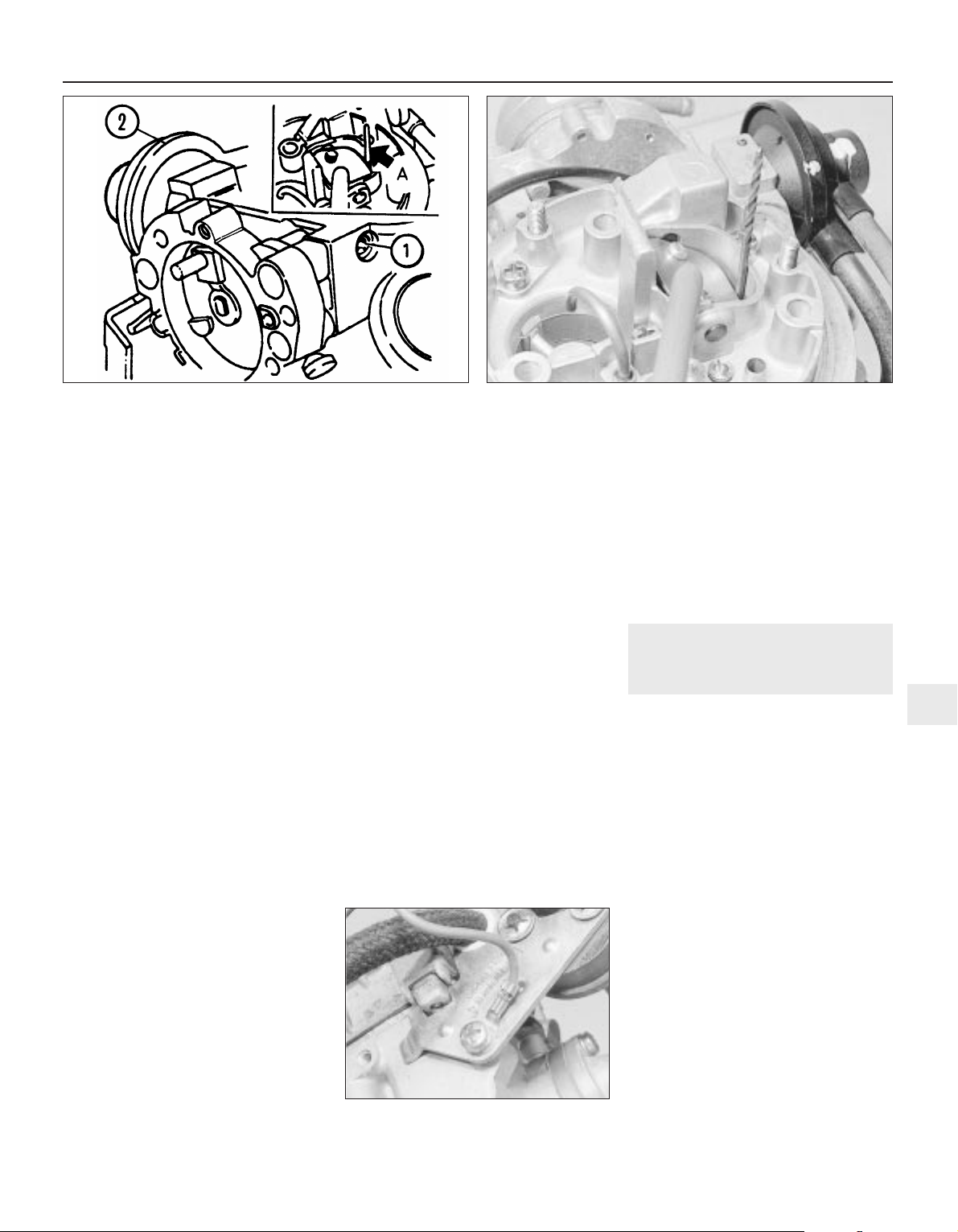
12 Using a drill shank of appropriate
diameter, or a similar item, measure the
clearance between the lower side of the
choke plate and the wall of the primary barrel
(see illustrations). Check that the clearance
is as given for the “small” choke pull-down
gap in the Specifications.
13 If adjustment is necessary, turn the
adjustment screw in the appropriate direction,
using an Allen key, until the clearance is
correct.
14 Now push the pull-down arm towards the
diaphragm unit as far as its stop, and hold the
arm in this position.
15 As before measure the clearance between
the lower side of the choke plate and the wall
of the primary barrel. Check that the
clearance is as given for the “large” choke
pull-down gap in the Specifications.
16 If adjustment is necessary, turn the
adjustment screw in the appropriate direction
until the clearance is correct.
17 Connect the bi-metal spring to the choke
lever, position the bi-metal housing on the
choke housing and loosely fit the securing
screws. Align the marks on the bi-metal
housing and the choke housing as noted
during removal, then tighten the securing
screws.
18 Refit the air box to the top of the
carburettor on completion.
Secondary pull-down solenoid
Removal
19 This unit operates in conjunction with the
main diaphragm unit.
20 To remove the solenoid unit, first continue
as described in Section 17, paragraphs 1 and
2.
21 Disconnect the diaphragm unit vacuum
pipe.
22 Disconnect the wiring plug, then unscrew
the securing screw, and withdraw the
solenoid unit and its mounting bracket from
the carburettor. Note that the securing screw
also secures the wiring plug earth lead (see
illustration).
Refitting
23 Refitting is a reversal of removal, but
ensure that the wiring plug earth lead is in
place under the solenoid bracket securing
screw.
21 Carburettor filter - removal
and refitting
3
Removal
1 A small tubular filter gauze is fitted into the
carburettor top cover’s fuel inlet union to
remove any particles of dirt from the fuel.
2 To ensure a clean fuel supply and to
prevent the risk of misfiring, poor starting or
other problems due to a restricted fuel supply,
this filter must be cleaned and/or renewed at
the interval specified in Chapter 1.
3 To reach the filter, remove the air cleaner or
air box, as applicable, then disconnect and
plug the hose from the fuel pump or vapour
separator to the top cover union.
4 Remove the filter by hooking it out with a
small screwdriver, or by snaring it with a long
thin screw (3 mm thread size, screwed
approximately 5 mm into the filter).
5 If the filter is blocked or heavily fouled, or if
it is torn, distorted or damaged in any way, it
must be renewed. If it is fit for further use,
clean it using a jet of compressed air or by
brushing away particles of dirt with an old soft
toothbrush. Then flushing it in clean solvent,
taking care not to allow any overspray to get
into your eyes; if petrol is used, take care to
prevent the risk of fire.
Fuel and exhaust systems - carburettor models 4A•11
20.12B Checking the vacuum pull-down gap using a twist drill
20.22 Secondary choke pull-down
solenoid securing screw and earth lead
20.12A Choke vacuum pull-down adjustment
1 Adjustment screw 2 Diaphragm unit A Twist drill
4A
Page 12
Refitting
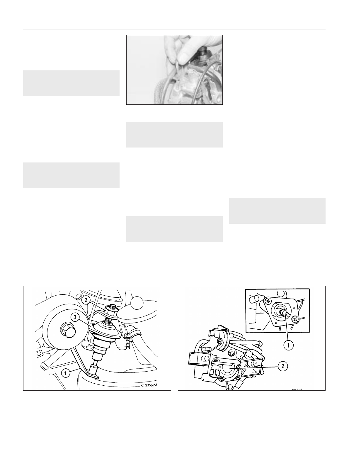
6 On refitting the filter, press it into the union
until it catches (see illustration). The
remainder of the reassembly procedure is the
reverse of removal.
22 Throttle valve dashpot
(automatic models) -
adjustment
2
1 Remove the air cleaner or air box, refer to
Section 3.
2 Ensure that the lever (see illustration) is in
the idling position.
3 Slacken the locknut and unscrew the
dashpot until a gap of 0.05 mm (0.002 in)
exists between the lever and the dashpot tip.
Then screw the dashpot downwards 2.5 full
turns and tighten the locknut.
4 Refit all removed components.
23 Throttle position sensor
(automatic transmission
models) - removal and refitting
2
Removal
1 Disconnect the battery earth lead.
2 Disconnect the wiring plug from the sensor.
3 Either unscrew the two securing screws
and withdraw the sensor from its bracket, or
unbolt the bracket.
Refitting
4 Refitting is the reverse of the removal
procedure, noting the following points.
a) Install the sensor when the throttle valve
is fully closed and ensure that the
adapter, “1” (see illustration), seats
correctly on the throttle valve spindle.
b) Tighten the screws carefully.
24 Idle speed increase valve -
testing
2
1 Certain models are fitted with an idle speed
increase valve that is attached to the side of
the carburettor.
2 To test the operation of this valve first
remove the air filter and vacuum hose.
3 With the valve’s plug connected, have
someone turn the ignition on (but do not start
the engine). A mechanical shifting noise
should be heard. If not replace the unit.
4 After refitting replace the vacuum hose and
air filter.
25 Idle cut-off solenoid (1.8 litre
models) - description and
testing
2
Note: Refer to Section 2 before proceeding
Description
1 On 1.8 litre models, the carburettor is fitted
with an idle cut-off solenoid. This is an
electrically operated valve, which interrupts
the idle mixture circuit when the ignition is
switched off, thus preventing the engine from
running-on (see illustration).
2 The idle cut-off solenoid is energised all the
time that the ignition is switched on. A
defective solenoid, or a break in its power
supply, will cause the engine to stall or idle
roughly, although it will run normally at speed.
Testing
3 If the operation of the solenoid is suspect,
first check that battery voltage is present at
the solenoid terminal when the ignition is
switched on. Use a 12 volt test lamp or similar
test device.
4 If no voltage is present, then the fault lies in
the wiring to the solenoid. If voltage is
present, the solenoid can be tested as
follows.
5 With the solenoid unscrewed from the
carburettor, connect the body of the solenoid
to the negative terminal of a 12 volt battery.
When the battery positive terminal is
connected to the solenoid centre terminal,
there should be an audible click, and the
needle at the tip of the solenoid should
retract.
6 A defective idle cut-off solenoid must be
renewed.
26 Inlet manifold - removal and
refitting
3
Note: Refer to Section 2 before proceeding. A
new manifold gasket must be used on refitting
Removal
1 Disconnect the battery negative lead.
2 Drain the cooling system, as described in
Chapter 3.
3 Proceed as described in Section 13,
paragraphs 2 to 7 inclusive, ignoring the
reference to coolant spillage in paragraph 5.
4A•12 Fuel and exhaust systems - carburettor models
21.6 Refitting the carburettor fuel filter
23.4 Throttle position sensor - models with automatic
transmission
1 Adapter 2 Sensor
22.2 Adjusting the throttle valve dashpot - models with
automatic transmission
1 Lever 2 Locknut 3 Dashpot
Page 13
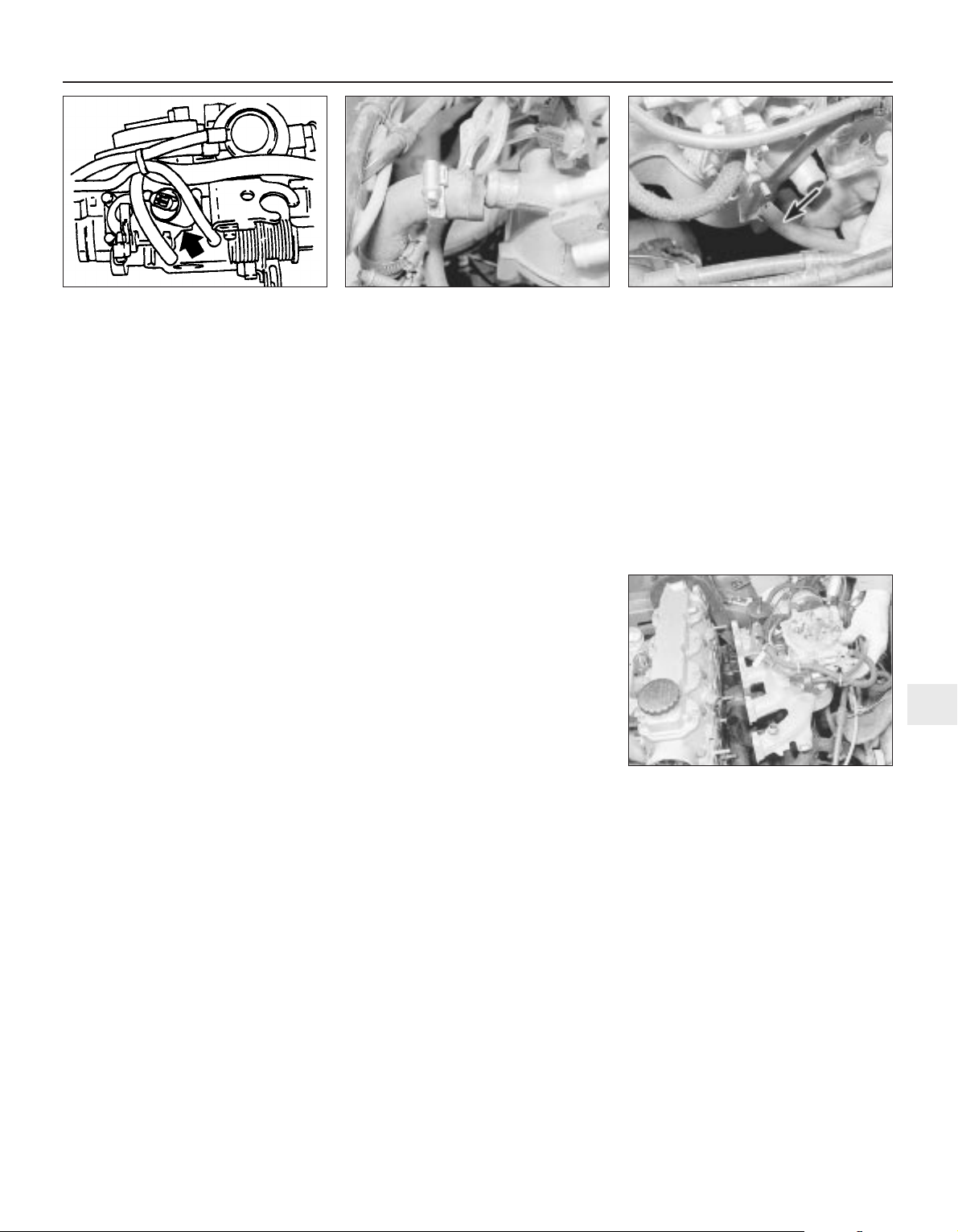
4 Disconnect the coolant hose from the rear
of the manifold (see illustration).
5 Where applicable, disconnect the camshaft
cover breather hose from the rear of the
manifold (see illustration).
6 Unscrew the union and disconnect the
brake servo vacuum hose from the manifold.
7 On 1.4 and 1.6 litre models, disconnect the
wiring from the temperature gauge sender.
8 Unscrew and remove the top alternator
mounting nut and bolt.
9 On 1.4 and 1.6 litre models, disconnect and
remove the stub hose that connects the
crankcase breather tube to the rear of the
camshaft housing.
10 Make a final check to ensure that all
relevant hoses, pipes and wires have been
disconnected.
11 Unscrew the securing nuts, and withdraw
the manifold from the cylinder head (see
illustration). Note the position of the rear
engine lifting bracket, which is secured by one
of the manifold nuts, and recover the manifold
gasket.
12 It is possible that some of the manifold
studs may be unscrewed from the cylinder
head when the manifold securing nuts are
unscrewed. In this event, the studs should be
screwed back into the cylinder head once the
manifold has been removed, using two
manifold nuts locked together.
13 If desired, the carburettor can be removed
from the manifold, referring to Section 13, if
necessary.
Refitting
14 Refitting is a reversal of removal,
remembering the following points.
15 If the carburettor has been removed from
the manifold, refit it, using a new gasket.
16 If the alternator mounting bracket has
been unbolted from the manifold, refit it
before refitting the manifold, as access to the
securing bolt is extremely limited once the
manifold is in place.
17 Refit the manifold using a new gasket,
and ensure that the engine lifting bracket is in
place under the relevant manifold nut. Tighten
the nuts to the specified torque.
18 Ensure that all relevant hoses, pipes and
wires are correctly reconnected.
19 Refill the cooling system, as described in
Chapter 3.
20 Check the throttle cable free play and
adjust if necessary, as described in Section
11.
21 If the carburettor has been disturbed,
check and if necessary adjust the idle speed
and mixture, as described in Section 14.
Fuel and exhaust systems - carburettor models 4A•13
26.5 . . .and the camshaft cover breather
hose (arrowed) from the inlet manifold -
1.6 litre model
26.11 Withdrawing the inlet manifold -
1.6 litre model
26.4 Disconnecting the coolant hose . . .
4A
25.1 Carburettor idle cut-off solenoid
(arrowed) - 1.8 litre models
Page 14

4A•14
Notes
Page 15

12
Wiper blades
Type . . . . . . . . . . . . . . . . . . . . . . . . . . . . . . . . . . . . . . . . . . . . . . . . . . . . 19 ins. Champion X-4803
Fuses
Rating:
Red . . . . . . . . . . . . . . . . . . . . . . . . . . . . . . . . . . . . . . . . . . . . . . . . . . . 10 A
Blue . . . . . . . . . . . . . . . . . . . . . . . . . . . . . . . . . . . . . . . . . . . . . . . . . . . 15 A
Yellow . . . . . . . . . . . . . . . . . . . . . . . . . . . . . . . . . . . . . . . . . . . . . . . . . 20 A
Green . . . . . . . . . . . . . . . . . . . . . . . . . . . . . . . . . . . . . . . . . . . . . . . . . 30 A
Torque wrench settings Nm lbf ft
Airbag unit to steering wheel . . . . . . . . . . . . . . . . . . . . . . . . . . . . . . . . . 10 7
Airbag control . . . . . . . . . . . . . . . . . . . . . . . . . . . . . . . . . . . . . . . . . . . . . 10 7
Brackets, passenger airbag . . . . . . . . . . . . . . . . . . . . . . . . . . . . . . . . . . 22 16
Passenger airbag to bracket . . . . . . . . . . . . . . . . . . . . . . . . . . . . . . . . . 8 6
Steering to column . . . . . . . . . . . . . . . . . . . . . . . . . . . . . . . . . . . . . . . . . 25 18
Chapter 12
Body electrical systems
Aerial - removal and refitting . . . . . . . . . . . . . . . . . . . . . . . . . . . . . . .47
Aerial mast, electric - removal and refitting . . . . . . . . . . . . . . . . . . . .48
Airbag - general . . . . . . . . . . . . . . . . . . . . . . . . . . . . . . . . . . . . . . . . .55
Airbag contact unit - removal and refitting . . . . . . . . . . . . . . . . . . . . .58
Airbag control unit - removal and refitting . . . . . . . . . . . . . . . . . . . . .61
Airbag unit, drivers side - removal and refitting . . . . . . . . . . . . . . . . .56
Airbag unit, passengers side - removal and refitting . . . . . . . . . . . . .59
Anti-theft alarm - general . . . . . . . . . . . . . . . . . . . . . . . . . . . . . . . . . .53
Anti-theft alarm system components - removal and refitting . . . . . . .54
Bracket, passenger airbag unit - removal and refitting . . . . . . . . . . .60
Brake lamp switch - removal and refitting . . . . . . . . . . . . . . . . . . . . .12
Central door locking components - removal and refitting . . . . . . . . .46
Check control system components - removal and refitting . . . . . . . .21
Cigarette lighter - removal and refitting . . . . . . . . . . . . . . . . . . . . . . .15
Clock - removal and refitting . . . . . . . . . . . . . . . . . . . . . . . . . . . . . . .16
Courtesy lamp switch - removal and refitting . . . . . . . . . . . . . . . . . . .10
Direction indicator/lighting switch - removal and refitting . . . . . . . . . .5
Electric door mirror switch - removal and refitting . . . . . . . . . . . . . . . .8
Electric window components - removal and refitting . . . . . . . . . . . . .44
Electric window controls - programming . . . . . . . . . . . . . . . . . . . . . .45
Electrical fault-finding - general information . . . . . . . . . . . . . . . . . . . . .2
Exterior lamp bulbs - renewal . . . . . . . . . . . . . . . . . . . . . . . . . . . . . . .34
Facia panel switches - removal and refitting . . . . . . . . . . . . . . . . . . . .7
Front indicator lamp unit - removal and refitting . . . . . . . . . . . . . . . .29
Front foglamp - removal, refitting and adjustment . . . . . . . . . . . . . . .31
Fuses and relays - general . . . . . . . . . . . . . . . . . . . . . . . . . . . . . . . . . .3
General information and precautions . . . . . . . . . . . . . . . . . . . . . . . . . .1
Handbrake “on” warning lamp switch - removal and refitting . . . . . .13
Headlamp aim adjustment motor - removal and refitting . . . . . . . . . .26
Headlamp dim-dip system - general, removal and refitting . . . . . . . .28
Headlamp unit - removal and refitting . . . . . . . . . . . . . . . . . . . . . . . .25
Headlamp washer fluid non-return valve - removal and refitting . . . .43
Headlamp wiper motor - removal and refitting . . . . . . . . . . . . . . . . . .40
Headlamps - alignment . . . . . . . . . . . . . . . . . . . . . . . . . . . . . . . . . . .27
Heated front seats - general . . . . . . . . . . . . . . . . . . . . . . . . . . . . . . . .17
Horn(s) - removal and refitting . . . . . . . . . . . . . . . . . . . . . . . . . . . . . .22
Ignition switch and lock cylinder - removal and refitting . . . . . . . . . . .4
Instrument panel - removal and refitting . . . . . . . . . . . . . . . . . . . . . .18
Instrument panel components - removal and refitting . . . . . . . . . . . .19
Interior lamp bulbs - renewal . . . . . . . . . . . . . . . . . . . . . . . . . . . . . . .24
Interior lamps - removal and refitting . . . . . . . . . . . . . . . . . . . . . . . . .23
Luggage compartment lamp switch - removal and refitting . . . . . . .11
Number plate lamp - removal and refitting . . . . . . . . . . . . . . . . . . . . .33
Oil pressure warning lamp switch - removal and refitting . . . . . . . . .14
Radio/cassette player - removal and refitting . . . . . . . . . . . . . . . . . . .50
Rear lamp unit - removal and refitting . . . . . . . . . . . . . . . . . . . . . . . .32
Reversing lamp switch . . . . . . . . . . . . . . . . . . . . . . . . .See Chapter 7A
Side repeater lamp - removal and refitting . . . . . . . . . . . . . . . . . . . . .30
Speakers - removal and refitting . . . . . . . . . . . . . . . . . . . . . . . . . . . .49
Speedometer cable - removal and refitting . . . . . . . . . . . . . . . . . . . .52
Steering wheel (with airbag) - removal and refitting . . . . . . . . . . . . . .57
Sunroof motor - removal and refitting . . . . . . . . . . . . . . . . . . . . . . . .51
Sunroof operating switch - removal and refitting . . . . . . . . . . . . . . . . .9
Tailgate wiper motor - removal and refitting . . . . . . . . . . . . . . . . . . . .39
Trip computer components - removal and refitting . . . . . . . . . . . . . .20
Wash/wipe switch - removal and refitting . . . . . . . . . . . . . . . . . . . . . .6
Washer fluid reservoir - removal and refitting . . . . . . . . . . . . . . . . . . .41
Washer nozzles - removal and refitting . . . . . . . . . . . . . . . . . . . . . . .37
Washer pump - removal and refitting . . . . . . . . . . . . . . . . . . . . . . . . .42
Windscreen wiper motor and linkage - removal and refitting . . . . . . .38
Wiper arms - removal and refitting . . . . . . . . . . . . . . . . . . . . . . . . . . .36
Wiper blades - renewal . . . . . . . . . . . . . . . . . . . . . . . . . . . . . . . . . . . .35
Wiring diagrams - general . . . . . . . . . . . . . . . . . . . . . . . . . . . . . . . . .62
12•1
Specifications
Contents
Easy, suitable for
novice with little
experience
Fairly easy, suitable
for beginner with
some experience
Fairly difficult,
suitable for competent
DIY mechanic
Difficult, suitable for
experienced DIY
mechanic
Very difficult,
suitable for expert DIY
or professional
Degrees of difficulty
5
4
3
2
1
Page 16
1 General information and
precautions
The electrical system is of 12-volt negative
earth type. Power for the lights and all
electrical accessories is supplied by a
lead/acid type battery, which is charged by
the alternator.
This Chapter covers repair and service
procedures for the various electrical
components not associated with engine.
Information on the battery, alternator and
starter motor can be found in Chapter 5.
It should be noted that, before working on
any component in the electrical system, the
battery negative terminal should first be
disconnected, to prevent the possibility of
electrical short-circuits and/or fires.
Whenever the occasion arises, carefully
check the routing of the wiring harness,
ensuring that it is correctly secured by the
clips or ties provided so that it cannot chafe
against other components. Carefully check
points such as the clutch cable bracket,
clutch housing and harness support bracket,
the inlet manifold, the horn mounting bracket,
the starter motor terminals, and the rear
bumper and number plate lamp.
If evidence is found of the harness having
chafed against other components, repair the
damage and ensure that the harness is
secured or protected so that the problem
cannot occur again.
2 Electrical fault-finding -
general information
Note: Refer to the precautions given in “Safety
first!” (at the beginning of this manual) and to
Section 1 of this Chapter before starting work.
The following tests relate to testing of the main
electrical circuits, and should not be used to
test delicate electronic circuits (such as antilock braking systems), particularly where an
electronic control module is used.
A typical electrical circuit consists of an
electrical component, any switches, relays,
motors, fuses, fusible links or circuit breakers
related to that component, and the wiring and
connectors that link the component to both
the battery and the chassis. To help to
pinpoint a problem in an electrical circuit,
wiring diagrams are included at the end of this
Chapter.
Before attempting to diagnose an electrical
fault, first study the appropriate wiring
diagram, to obtain a complete understanding
of the components included in the particular
circuit concerned. The possible sources of a
fault can be narrowed down by noting
whether other components related to the
circuit are operating properly. If several
components or circuits fail at one time, the
problem is likely to be related to a shared fuse
or earth connection.
Electrical problems usually stem from
simple causes, such as loose or corroded
connections, a faulty earth connection, a
blown fuse, a melted fusible link, or a faulty
relay (refer to Section 3 for details of testing
relays). Visually inspect the condition of all
fuses, wires and connections in a problem
circuit before testing the components. Use
the wiring diagrams to determine which
terminal connections will need to be checked,
to pinpoint the trouble-spot.
The basic tools required for electrical faultfinding include the following:
a) a circuit tester or voltmeter (a 12-volt bulb
with a set of test leads can also be used
for certain tests).
b) a self-powered test light (sometimes
known as a continuity tester).
c) an ohmmeter (to measure resistance).
d) a battery.
e) a set of test leads.
f) a jumper wire, preferably with a circuit
breaker or fuse incorporated, which can
be used to bypass suspect wires or
electrical components.
Before attempting to locate a problem with
test instruments, use the wiring diagram to
determine where to make the connections.
To find the source of an intermittent wiring
fault (usually due to a poor or dirty
connection, or damaged wiring insulation), a
“wiggle” test can be performed on the wiring.
This involves wiggling the wiring by hand, to
see if the fault occurs as the wiring is moved.
It should be possible to narrow down the
source of the fault to a particular section of
wiring. This method of testing can be used in
conjunction with any of the tests described in
the following sub-Sections.
Apart from problems due to poor
connections, two basic types of fault can
occur in an electrical circuit - open-circuit, or
short-circuit.
Open-circuit faults are caused by a break
somewhere in the circuit, which prevents
current from flowing. An open-circuit fault will
prevent a component from working, but will
not cause the relevant circuit fuse to blow.
Short-circuit faults are caused by a “short”
somewhere in the circuit, which allows the
current flowing in the circuit to “escape” along
an alternative route, usually to earth. Shortcircuit faults are normally caused by a
breakdown in wiring insulation, which allows a
feed wire to touch either another wire, or an
earthed component such as the bodyshell. A
short-circuit fault will normally cause the
relevant circuit fuse to blow.
Finding an open-circuit
To check for an open-circuit, connect one
lead of a circuit tester or voltmeter to either
the negative battery terminal or a known good
earth.
Connect the other lead to a connector in
the circuit being tested, preferably nearest to
the battery or fuse.
Switch on the circuit, remembering that
some circuits are live only when the ignition
switch is moved to a particular position.
If voltage is present (indicated either by the
tester bulb lighting or a voltmeter reading, as
applicable), this means that the section of the
circuit between the relevant connector and
the battery is problem-free.
Continue to check the remainder of the
circuit in the same fashion.
When a point is reached at which no
voltage is present, the problem must lie
between that point and the previous test point
with voltage. Most problems can be traced to
a broken, corroded or loose connection.
Finding a short-circuit
To check for a short-circuit, first disconnect
the load(s) from the circuit (loads are the
components that draw current from a circuit,
such as bulbs, motors, heating elements, etc.).
Remove the relevant fuse from the circuit,
and connect a circuit tester or voltmeter to the
fuse connections.
Switch on the circuit, remembering that
some circuits are live only when the ignition
switch is moved to a particular position.
If voltage is present (indicated either by the
tester bulb lighting or a voltmeter reading, as
applicable), this means that there is a shortcircuit.
If no voltage is present, but the fuse still
blows with the load(s) connected, this indicates
an internal fault in the load(s).
Finding an earth fault
The battery negative terminal is connected
to “earth” (the metal of the
engine/transmission and the car body), and
most systems are wired so that they only
receive a positive feed. The current returning
through the metal of the car body. This means
that the component mounting and the body
form part of that circuit. Loose or corroded
mountings can therefore cause a range of
electrical faults, ranging from total failure of a
circuit, to a puzzling partial fault. In particular,
lights may shine dimly (especially when
another circuit sharing the same earth point is
in operation). Motors (e.g. wiper motors or the
radiator cooling fan motor) may run slowly,
and the operation of one circuit may have an
affect on another. Note that on many vehicles,
earth straps are used between certain
components, such as the engine/transmission
and the body, usually where there is no metal-
12•2 Body electrical systems
Warning: Before carrying out
any work on the electrical
system, read through the
precautions given in “Safety
first!” at the beginning of this manual, and
in Chapter 5.
Caution: If the radio/cassette player fitted
to the vehicle is one with an anti-theft
security code, as the standard unit is, refer
to “Radio/cassette player anti-theft system
- precaution” in the Reference Section of
this manual before disconnecting the
battery.
Page 17
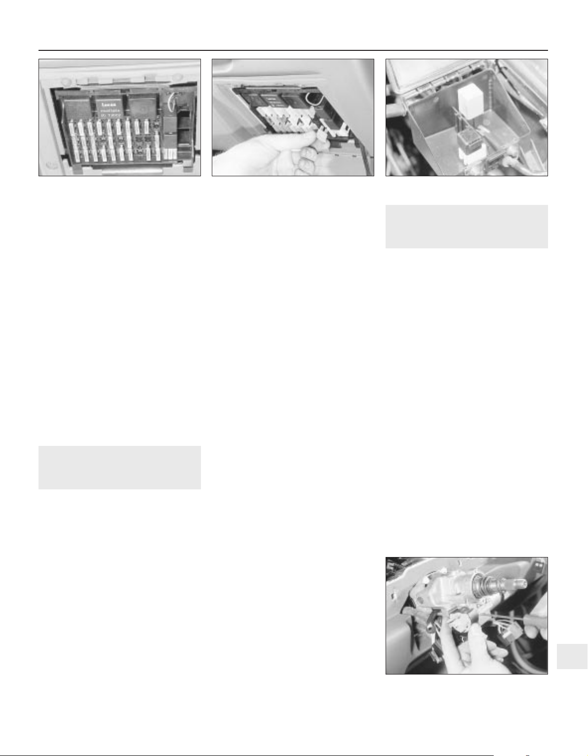
to-metal contact between components, due
to flexible rubber mountings, etc.
To check whether a component is properly
earthed, disconnect the battery, and connect
one lead of an ohmmeter to a known good
earth point. Connect the other lead to the wire
or earth connection being tested. The
resistance reading should be zero; if not,
check the connection as follows.
If an earth connection is thought to be
faulty, dismantle the connection, and clean
back to bare metal both the bodyshell and the
wire terminal or the component earth
connection mating surface. Be careful to
remove all traces of dirt and corrosion, then
use a knife to trim away any paint, so that a
clean metal-to-metal joint is made. On
reassembly, tighten the joint fasteners
securely; if a wire terminal is being refitted,
use serrated washers between the terminal
and the bodyshell, to ensure a clean and
secure connection. When the connection is
remade, prevent the onset of corrosion in the
future by applying a coat of petroleum jelly or
silicone-based grease.
3 Fuses and relays - general
Fuses
1 Fuses are designed to break a circuit when
a predetermined current is reached, to protect
the components and wiring which could be
damaged by excessive current flow. Any
excessive current flow will be due to a fault in
the circuit, usually a short-circuit (Section 2).
2 The main fuses and relays are located in a
panel at the lower right-hand side of the facia,
under a hinged cover (see illustration).
3 The circuits protected by the various fuses
and relays are marked on the inside of the
panel cover.
4 A blown fuse can be recognised from its
melted or broken wire.
5 To remove a fuse, first ensure that the
relevant circuit is switched off. Then open the
cover and pull the relevant fuse or relay from the
panel (see illustration). If desired, the lower
end of the panel can be tilted forwards, after
releasing the retaining clips to improve access.
6 Before renewing a blown fuse, trace and
rectify the cause, and always use a fuse of the
correct rating. Never substitute a fuse of a
higher rating, or make temporary repairs using
wire or metal foil, as more serious damage or
even fire could result.
7 Spare fuses are provided in the blank
terminal positions in the fusebox.
8 Note that the fuses are colour-coded, see
Specifications. Refer to the wiring diagrams
for details of the fuse ratings and the circuits
protected.
Relays
9 A relay is an electrically operated switch,
which is used for the following reasons:
a) A relay can switch a heavy current
remotely from the circuit in which the
current is flowing, allowing the use of
lighter-gauge wiring and switch contacts.
b) A relay can receive more than one control
input, unlike a mechanical switch.
c) A relay can have a timer function - for
example, the intermittent wiper relay.
10 Most of the relays are located at the rear
of the main fusebox (remove the securing
screws and pull the fusebox forwards to
improve access). The rear wiper motor relay is
located in the tailgate, behind the tailgate trim
panel. On some models, additional enginerelated relays are located in the relay box
mounted on the left-hand side of the engine
compartment.
11 On certain models, additional relays are
located in a box at the left-hand rear of the
engine compartment (see illustration).
12 If a circuit or system controlled by a relay
develops a fault, and the relay is suspect,
operate the system. If the relay is functioning, it
should be possible to hear it “click” as it is
energised. If this is the case, the fault lies with
the components or wiring of the system. If the
relay is not being energised, then either the
relay is not receiving a main supply or a
switching voltage, or the relay itself is faulty.
Testing is by the substitution of a known good
unit, but be careful - while some relays are
identical in appearance and in operation, others
look similar but perform different functions.
13 To remove a relay, first ensure that the
relevant circuit is switched off. The relay can
then simply be pulled out from the socket,
and pushed back into position.
4 Ignition switch and lock
cylinder - removal and
refitting
3
Removal
1 Disconnect the battery negative lead.
2 Turn the steering wheel as necessary to
expose the two front steering column shroud
securing screws, which are covered by plastic
caps. Prise out the caps and remove the
screws.
3 Remove the three securing screws from the
underside of the lower column shroud, then
remove both the upper and lower shrouds.
4 To remove the lock cylinder, insert the
ignition key and turn it to position “II”.
5 Insert a thin rod into the hole in the lock
housing, then press the rod to release the
detent spring, and pull out the lock cylinder
using the key.
6 The ignition switch is secured to the
steering lock housing by two grub screws.
Disconnect the wiring plug, and remove the
screws to extract the switch (see illustration).
Removal of the steering wheel, may aid
removal. Refer to Chapter 10 or Section 57, as
applicable. It is recommended that the switch
and the lock cylinder are not both removed at
the same time, so that their mutual alignment
is not lost.
Refitting
7 Refitting is a reversal of removal.
Body electrical systems 12•3
3.11 Relays in engine compartment box -
2.0 litre SRi model shown
4.6 Removing an ignition switch securing
screw
3.5 Removing a fuse -
2.0 litre model shown
3.2 Main fuses and relays in facia panel -
2.0 litre SRi model shown
12
Page 18
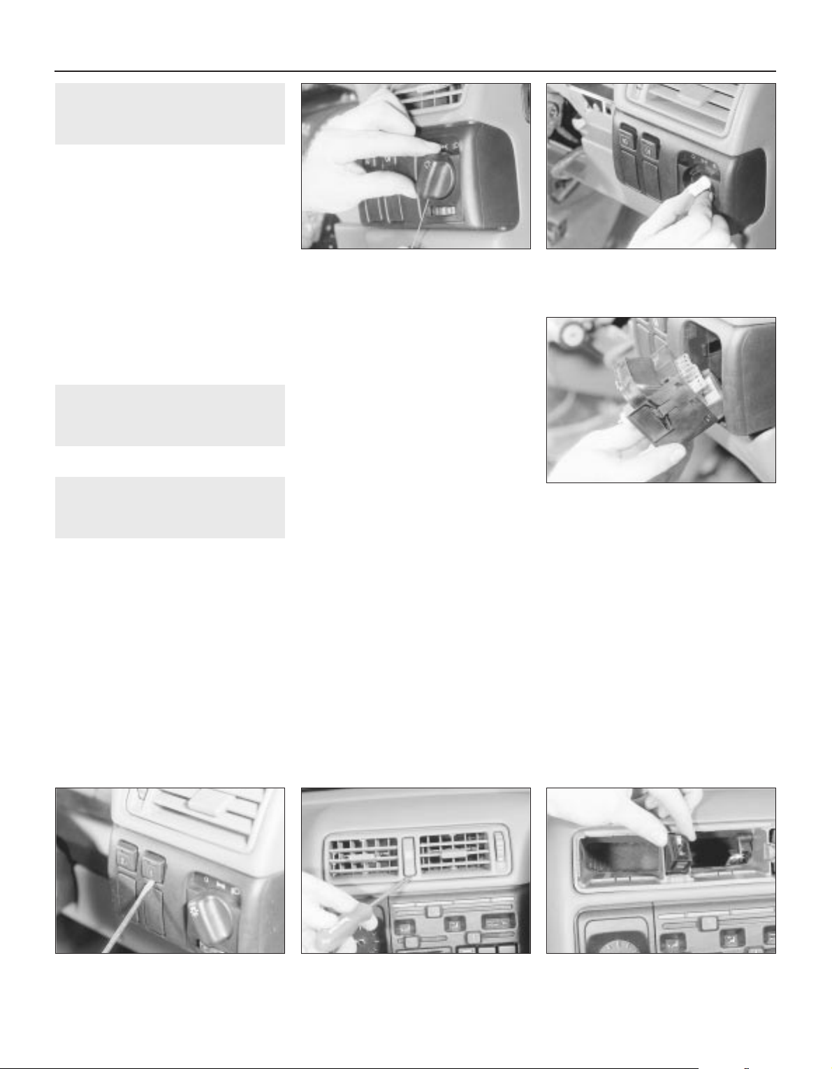
5 Direction indicator/lighting
switch - removal and refitting
2
Removal
1 Disconnect the battery negative lead.
2 Turn the steering wheel as necessary to
expose the two front steering column shroud
securing screws, which are covered by plastic
caps. Prise out the caps and remove the
screws.
3 Remove the three securing screws from the
underside of the lower column shroud, then
remove both the upper and lower shrouds.
4 Disconnect the wiring plug from the switch.
5 Depress the switch retaining clip, and
withdraw the switch from the housing.
Refitting
6 Refitting is a reversal of removal.
6 Wash/wipe switch - removal
and refitting
2
Proceed as described in Section 5.
7 Facia panel switches -
removal and refitting
2
1 Disconnect the battery negative lead.
Lighting switch
Removal
2 Turn the switch to the “dipped beam on”
position, then insert a small screwdriver or rod
through the hole in the bottom of the switch
knob to depress the knob retaining clip. Pull
the knob from the switch (see illustration).
3 Press the two now-exposed switch
securing clips towards the switch spindle,
then pull the switch from the facia and
disconnect the wiring plug (see illustrations).
4 Note that the switch assembly cannot be
dismantled, and if any part of the switch is
faulty, the complete assembly must be
renewed.
Refitting
5 Refitting is a reversal of removal.
Push-button switches
Removal
6 First check beneath the switch, if there is a
small hole in the facia, insert a slim
screwdriver or metal rod into it. Release the
switch retaining spring clip by pressing it
upwards against the switch, then remove the
switch and disconnect its wiring. If there is no
hole, remove the switch by prising it out of the
facia using a small screwdriver. Lever gently
under the switch’s lower edge (use adhesive
tape or a piece of card to protect the facia’s
finish). Disconnect the switch wiring plug and
withdraw the switch (see illustration).
Refitting
7 Refitting is a reversal of removal.
Headlamp aim adjustment
switch
8 The procedure is as described for pushbutton switches.
Hazard warning switch
Removal
9 Using a screwdriver, carefully prise the cap
from the switch (see illustration).
10 Using a screwdriver with a piece of card
under the blade to avoid damage to the facia
trim, prise the ventilation nozzle from the
facia.
11 Prise the switch from the facia and
disconnect the wiring (see illustration).
Refitting
12 Refitting is a reversal of removal.
Heater blower motor switch
Removal
13 Remove the heater control panel, as
described in Chapter 11.
14 Disconnect the wiring plug from the
switch, if not already done.
15 Prise the switch out from the rear of the
heater control panel.
Refitting
16 Refitting is a reversal of removal, but refer
to Chapter 11, when refitting the heater
control panel.
12•4 Body electrical systems
7.2 Using a thin rod to depress the
lightning switch knob retaining clip
7.3B . . . then pull the switch from the facia
7.11 Withdrawing the hazard warning
flasher switch from the facia
7.9 Prising the cap from the hazard
warning flasher switch
7.6 Prising a push-button switch from the
facia
7.3A Press the switch securing clips
towards the switch spindle . . .
Page 19
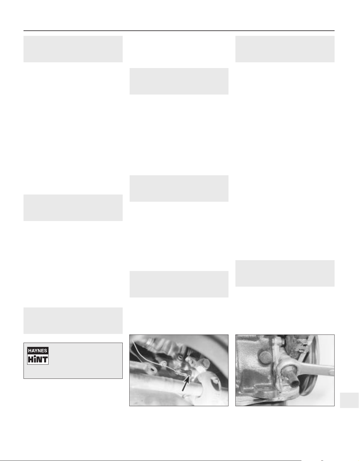
8 Electric door mirror switch -
removal and refitting
2
Removal
1 Disconnect the battery negative lead.
2 Prise the plastic surround from the door
interior handle.
3 Free the trim panel from the top edge of the
door by releasing the securing clips. This can
be done using a screwdriver, but it is
preferable to use a forked tool, to minimise
the possibility of damage to the trim panel and
the clips.
4 Note the position of the mirror switch wiring
connector in the bracket at the top of the
door, then separate the two halves of the
connector.
5 Prise the switch from the door trim panel,
and feed the wiring through the panel.
Refitting
6 Refitting is a reversal of removal, but ensure
that the wiring is correctly routed, so as not to
foul the door interior handle mechanism.
9 Sunroof operating switch -
removal and refitting
2
Removal
1 Disconnect the battery negative lead.
2 Prise the courtesy lamp from the roof trim
panel, and disconnect the wiring.
3 Remove the two trim panel securing
screws, and withdraw the trim panel from the
roof, disconnecting the wiring from the
sunroof operating switch.
4 Release the securing clips, then pull the
switch from the rear face of the trim panel.
Refitting
5 Refitting is a reversal of removal.
10 Courtesy lamp switch -
removal and refitting
2
Removal
1 Disconnect the battery negative lead.
2 Open the door and remove the switch
securing screw.
3 Withdraw the switch from the door pillar,
and pull the wiring out sufficiently to prevent it
from springing back into the pillar.
4 Disconnect the wiring and remove the
switch.
Refitting
5 Refitting is a reversal of removal.
11 Luggage compartment lamp
switch - removal and refitting
2
Removal
1 Disconnect the battery negative lead.
2 Open the boot lid or tailgate, as applicable,
and remove the switch securing screw.
3 Withdraw the switch from the body panel,
and pull the wiring out sufficiently to prevent it
from springing back into the body.
4 Disconnect the wiring and remove the
switch.
Refitting
5 Refitting is a reversal of removal.
12 Brake lamp switch - removal
and refitting
2
Removal
1 Disconnect the battery negative lead.
2 Remove the lower trim panel from the
driver’s footwell.
3 Disconnect the wiring plug from the brake
lamp switch, then twist the switch
anti-clockwise and remove it from its bracket.
Refitting
4 Refitting is a reversal of removal.
13 Handbrake “on” warning
lamp switch - removal and
refitting
3
For access to the switch, the handbrake
lever must be removed. Removal and refitting
of the switch is described as part of the
handbrake lever removal and refitting
procedure, in Chapter 9.
14 Oil pressure warning lamp
switch - removal and refitting
3
Removal
1 Disconnect the battery negative lead.
2 The switch is screwed into the oil pump, on
the inlet manifold side of the engine. On 1.4
and 1.6 litre (except C16 NZ2), models the
switch projects at right-angles to the
crankshaft axis, while on C16 NZ2, 1.8 and
2.0 litre models it is parallel to the crankshaft
(see illustration).
3 In most cases the switch can be reached
quite easily from above. However, on some
models access will be easier if the front of the
vehicle is jacked up and supported on axle
stands (see “Jacking and Vehicle Support”)
(ensure that the handbrake is securely
applied) and the front right-hand roadwheel is
removed.
4 Disconnect the switch wire and use a
spanner to unscrew the switch (see
illustration). As you withdraw the switch,
swiftly plug the hole in the oil pump to
minimise the loss of oil and to prevent the
entry of dirt.
Refitting
5 Refitting is the reverse of the removal
procedure; tighten the switch securely but do
not overtighten it, reconnect its wire, then
check and if necessary top-up the oil level, as
described in Chapter 1. Wash off any spilt oil
and check for leaks when the engine is
restarted.
15 Cigarette lighter - removal
and refitting
2
Removal
1 Disconnect the battery negative lead.
2 Slide the ashtray/cigarette lighter assembly
from the facia, then disconnect the wiring and
slide the illumination bulb from the cigarette
lighter.
Body electrical systems 12•5
14.4 Unscrewing the oil pressure warning
lamp switch -
SOHC model (engine removed)
14.2 Oil pressure warning lamp switch
(arrowed) viewed from underneath vehicle
- SOHC model
12
Tape the wiring to the door
pillar, to prevent if falling
back into the door pillar.
Alternatively, tie a piece of
string to the wiring to retrieve it.
Page 20

3 To remove the cigarette lighter assembly,
simply pull it from the illumination ring
assembly. If desired, the illumination ring
assembly can be removed, by pulling it from
the housing after depressing the retaining
clips.
Refitting
4 Refitting is a reversal of removal.
16 Clock - removal and refitting
2
Removal
1 Disconnect the battery negative lead.
2 Using a thin-bladed screwdriver, carefully
prise the clock from the facia panel.
3 Disconnect the wiring plugs and withdraw
the clock (see illustration).
Refitting
4 Refitting is a reversal of removal.
17 Heated front seats - general
2
Heating pads are fitted to the front seats of
some models. Before attempting to remove a
seat so equipped, disconnect the battery and
the leads from the heating pad.
18 Instrument panel - removal
and refitting
3
Removal
1 Disconnect the battery negative lead.
2 Remove the steering wheel, (Chapter 10).
3 Remove the steering column shrouds, and
the instrument panel upper and lower trim
panels, (Chapter 11).
4 Remove the single upper, and two lower,
instrument panel securing screws (see
illustration).
5 Carefully withdraw the instrument panel,
and disconnect the speedometer cable and
the two wiring plugs. Note that the
speedometer cable is retained by a clip, which
must be pressed towards the speedometer to
release the cable (see illustration).
6 If desired, the instrument panel can be
dismantled, with reference to Section 19.
Refitting
7 Refitting is a reversal of removal, but ensure
that the speedometer cable is not kinked or
twisted between the instrument panel and the
bulkhead as the panel is refitted.
19 Instrument panel
components - removal and
refitting
3
1 With the instrument panel removed, as
described in Section 18, continue as follows.
Panel illumination and warning
lamp bulbs
Removal
2 Twist the relevant bulbholder clockwise,
and withdraw it from the printed circuit board
on the rear of the instrument panel (see
illustration).
3 The bulbs are integral with the bulbholders,
and must be renewed as a unit.
Refitting
4 Refitting is a reversal of removal.
Voltage stabiliser
Removal
5 Remove the single securing screw from the
rear of the instrument panel, then pull the
voltage stabiliser from the contacts on the
printed circuit board (see illustration).
Refitting
6 Refitting is a reversal of removal.
Fuel and temperature gauges “low series” models
Removal
7 Pull the trip meter reset pin from the front of
the panel.
8 Release the two retaining clips at the top of
the panel, and remove the panel shroud (see
illustration).
9 Unscrew the two securing nuts, and
withdraw the relevant gauge through the front
of the instrument panel.
12•6 Body electrical systems
16.3 Disconnecting the wiring plugs from
the clock
18.5 Disconnecting an instrument panel
wiring plug. Note speedometer cable
retaining clip (arrowed)
19.8 Removing the instrument panel
shroud
19.5 Instrument panel voltage stabiliser
(arrowed)
19.2 Withdrawing an instrument panel
illumination lamp bulb
18.4 Unscrewing a lower instrument panel
securing screw
Page 21
Refitting
10 Refitting is a reversal of removal.
Fuel and temperature gauge
assembly - “high series” models
11 The procedure is as described in
paragraphs 7 to 10 inclusive, except that the
gauge assembly is secured by four nuts.
Tachometer
12 The procedure is as described in
paragraphs 7 to 10 inclusive except that the
tachometer is secured by three nuts (see
illustration).
Speedometer
Removal
13 Proceed as described in paragraphs 7
and 8.
14 Extract the four securing screws from the
rear of the panel (see illustration).
Refitting
15 Refitting is a reversal of removal.
Printed circuit board
Removal
16 Remove all bulbs and instruments, and
the voltage stabiliser, as described previously
in this Section.
17 Carefully peel the printed circuit board
from the instrument panel.
Refitting
18 Refitting is a reversal of removal, but
ensure that the printed circuit board is seated
correctly on the rear of the instrument panel.
20 Trip computer components -
removal and refitting
2
1 Disconnect the battery lead.
Display module
Removal
2 Using a thin-bladed screwdriver, carefully
prise the module from the facia panel.
3 Disconnect the wiring plug and withdraw
the module.
Refitting
4 Refitting is a reversal of removal.
Display module illumination bulb
Removal
5 Remove the display module, as described
previously in this Section.
6 Using a length of rubber sleeving of similar
diameter, or an alternator tool, extract the
bulb by inserting the tool through the hole in
the side of the display module (see
illustration).
Refitting
7 Refitting is a reversal of removal.
Operating switch
Removal
8 Remove the rear section of the centre
console, as described in Chapter 11.
9 Release the wiring plug from the switch
using a screwdriver.
10 Lift the switch, then pull it down and out
from the centre console.
Refitting
11 Refitting is a reversal of removal.
Outside air temperature sensor
Removal
12 The sensor is located at the left-hand end
of the front bumper (see illustration).
13 Prise the cover cap from the bumper, then
unclip the sensor, and disconnect the wiring
plug.
Refitting
14 Refitting is a reversal of removal.
21 Check control system
components - removal and
refitting
3
1 Disconnect the battery negative lead.
Warning lamp bulbs
2 The warning lamp bulbs are located in the
instrument panel, and removal and refitting
are described in Section 19.
Control module
Removal
3 The control module is located behind the
passenger side of the facia, above the
glovebox.
4 Remove the glovebox assembly, as
described in Chapter 11.
5 Disconnect the control module wiring plug,
then release the control module from its
mounting and withdraw the unit.
Refitting
6 Refitting is a reversal of removal.
Coolant level sensor
Removal
7 The coolant level sensor is integral with the
coolant expansion tank cap.
8 Disconnect the wiring from the top of the
cap, then unscrew the cap and withdraw it
from the expansion tank.
9 If faulty, the complete cap assembly must
be renewed.
Refitting
10 Refitting is a reversal of removal.
Washer fluid level sensor
Removal
11 The sensor is mounted in the side of the
fluid reservoir.
12 Disconnect the wiring from the sensor,
then unscrew the sensor from the fluid
reservoir. If the fluid level is above the level of
the sensor, be prepared for fluid spillage.
Refitting
13 Refitting is a reversal of removal.
Body electrical systems 12•7
20.6 Removing the trip computer display
module illumination bulb
20.12 Trip computer outside air
temperature sensor location (arrowed)
19.14 Speedometer securing screws
(arrowed)
19.12 Tachometer securing nuts (arrowed)
12
Page 22
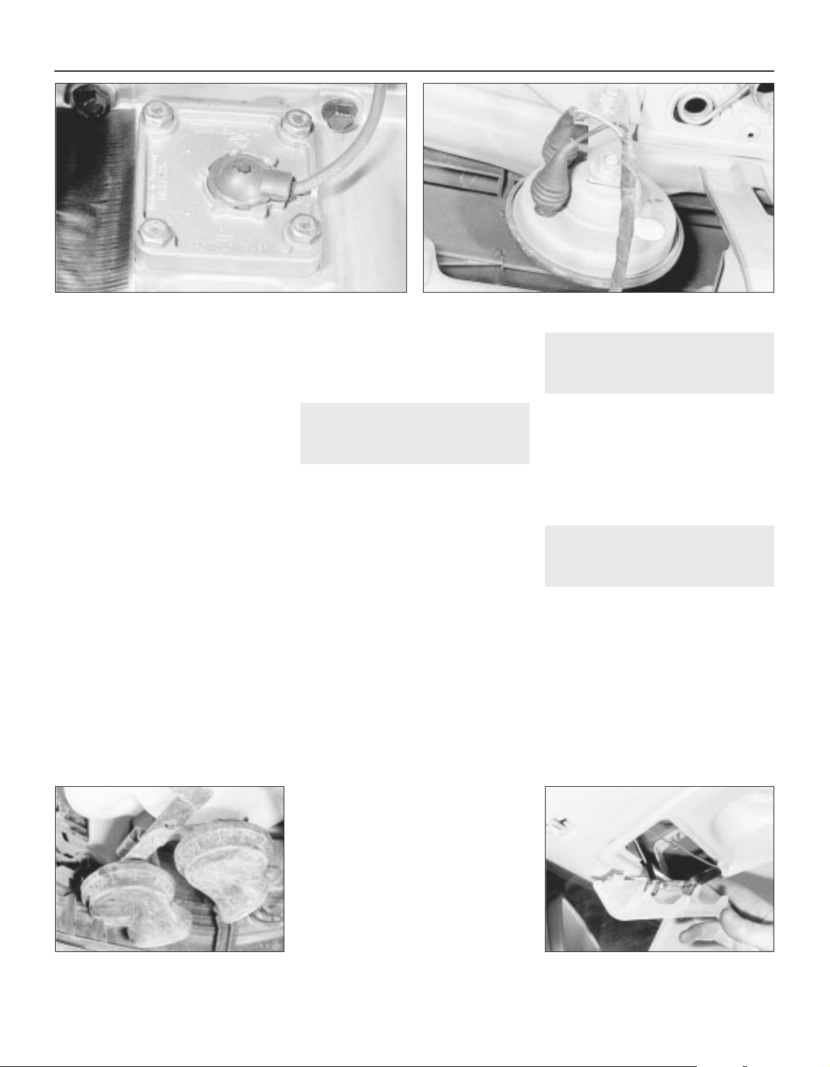
Brake fluid level sensor
14 The procedure is as described for the
coolant level sensor in paragraphs 7 to 10
inclusive.
Engine oil level sensor
Removal
15 Apply the handbrake, jack up the front of
the vehicle, and support securely on axle
stands (see “Jacking and Vehicle Support”)
positioned under the body side members.
16 On DOHC models, remove the engine
undershield, as described in Chapter 11.
17 Disconnect the sensor wiring plug.
18 Unscrew the three or four sensor securing
screws, as applicable, and withdraw the
sensor, manipulating the float through the hole
in the sump (see illustration). Recover the
sealing ring. Be prepared for some oil spillage.
19 Examine the condition of the sealing ring,
and renew if necessary.
Refitting
20 Refitting is a reversal of removal. On
completion, check, and if necessary top-up,
the engine oil level.
Bulb failure sensor
Removal
21 The bulb failure sensor is mounted behind
the fuse/relay panel in the facia.
22 Release the retaining clips from the lower
end of the fuse/relay panel, and tilt it forwards.
23 Reach up behind the fuse/relay panel, and
pull the sensor from its socket.
Refitting
24 Refitting is a reversal of removal.
22 Horn(s) - removal and refitting
2
1 On models with a single horn, the horn is
located in front of the radiator. On models
with twin horns, the horns are located beneath
the washer fluid reservoir, at the left-hand end
of the front bumper.
Single horn
Removal
2 Disconnect the battery negative lead.
3 Remove the radiator grille panel, with
reference to Chapter 11.
4 Disconnect the wiring from the rear of the
horn.
5 Reach up behind the mounting bracket, and
unscrew the single nut securing the horn to the
bracket (see illustration). Withdraw the horn.
Refitting
6 Refitting is a reversal of removal.
Twin horns
Removal
7 Disconnect the battery negative lead.
8 Apply the handbrake, then jack up the front
of the vehicle, and support securely on axle
stands (see “Jacking and Vehicle Support”)
positioned under the body side members.
9 Remove the securing screws, and withdraw
the plastic cover (where fitted) from the
bumper/front wing to expose the horns.
10 Remove the bolt securing the horn
mounting bracket to the bracket below the
washer fluid reservoir (see illustration).
11 Withdraw the horns and disconnect the
wiring.
12 If desired, the horns can be unbolted from
the bracket.
Refitting
13 Refitting is a reversal of removal.
23 Interior lamps - removal and
refitting
2
Removal
1 Disconnect the battery negative lead.
2 Using a thin-bladed screwdriver, prise the
lamp from its location and disconnect the
wiring (see illustration).
Refitting
3 Refitting is a reversal of removal.
24 Interior lamp bulbs - renewal
1
1 Disconnect the battery negative lead.
Courtesy lamp
Note: Some later models are fitted with
courtesy lamps for the rear seat passengers,
as well as front.
Removal
2 Using a thin-bladed screwdriver, prise the
lamp from its location and disconnect the
wiring.
3 On models fitted with a courtesy lamp with
integral map reading lamps, the lens must be
levered from the housing for access to the
bulbs.
12•8 Body electrical systems
21.18 Engine oil level sensor - DOHC model
22.10 Horn mounting bracket securing
bolt (arrowed) - twin horned model
23.2 Withdrawing the courtesy lamp
22.5 Horn viewed from behind with radiator removed - single
horned model
Page 23
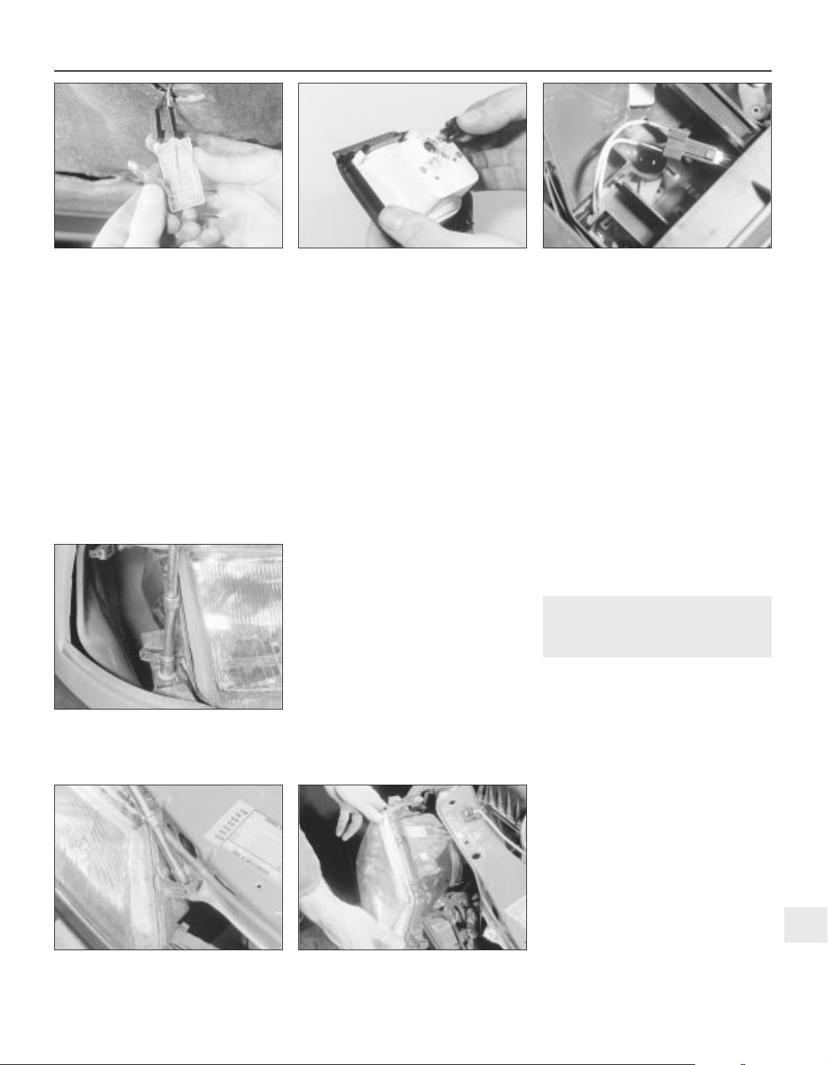
4 Remove the courtesy lamp bulbs by
carefully prising it from its location using a
thin-bladed screwdriver. Where applicable,
the map reading lamp bulbs are a push fit in
the bulbholders.
Refitting
5 Refitting is a reversal of removal.
Glovebox lamp
Removal
6 Using a thin-bladed screwdriver, prise the
lamp from its location and disconnect the
wiring.
7 Carefully prise the bulb from the lamp.
Refitting
8 Refitting is a reversal of removal.
Luggage compartment,
underbonnet and kerb lamps
Removal
9 Using a thin-bladed screwdriver, prise the
lamp from its location; disconnect the wiring.
10 Carefully prise the bulb from the lamp
(see illustration).
Refitting
11 Refitting is a reversal of removal
Cigarette lighter illumination lamp
Removal
12 Slide the ashtray/cigarette lighter
assembly from the facia, then disconnect the
wiring and pull the bulbholder from the rear of
the cigarette lighter housing.
13 The bulb is a push fit in the bulbholder.
Refitting
14 Refitting is a reversal of removal.
Clock illumination lamp
15 Remove the clock, (Section 16).
16 Twist the bulbholder and pull it from the
rear of the clock (see illustration).
17 The bulb is a push fit in the bulbholder.
Trip computer display module
illumination lamp
18 Refer to Section 20.
Heater control panel
illumination lamp
Removal
19 Remove the heater control panel, as
described in Chapter 11.
20 Pull the bulbholder from the rear of the
control panel (see illustration).
21 The bulb is a push fit in the bulbholder.
Refitting
22 Refitting is a reversal of removal.
Facia panel switch illumination
lamp
23 If a bulb fails in one of the facia panel
switches, the complete switch assembly must
be renewed, as described in Section 7, as no
individual spare parts are available.
Vanity mirror illumination lamp
Removal
24 Lower the sunvisor and, using a
thin-bladed screwdriver, prise out the mirror
and diffuser assembly. Pull the bulb(s) from
the spring contacts.
Refitting
25 Refitting is a reversal of removal.
25 Headlamp unit - removal and
refitting
2
Removal
1 Remove the radiator grille panel, as
described in Chapter 11.
2 Remove the front indicator lamp unit, as
described in Section 29.
3 Remove the cover from the rear of the
headlamp unit, and disconnect the wiring
plugs from the bulbs.
4 If applicable, disconnect the wiring plug
from the headlamp aim adjustment motor.
5 Remove the three securing screws, and
withdraw the headlamp unit (see
illustrations). Feed the wiring through the
headlamp casing as it is removed.
6 If required, the headlamp lens can be
removed by releasing the spring clips around
its edge.
Refitting
7 Refitting is a reversal of removal.
8 On completion, have the headlamp
alignment checked, with reference to
Section 27.
Body electrical systems 12•9
24.20 Heater control panel illumination
lamp bulbholder withdrawn
25.5C Withdrawing a headlamp unit25.5B Unscrewing an upper headlamp
securing screw
25.5A Unscrewing the lower headlamp
securing screw
24.16 Removing the clock illumination
lamp bulbholder
24.10 Removing the underbonnet lamp
bulb
12
Page 24
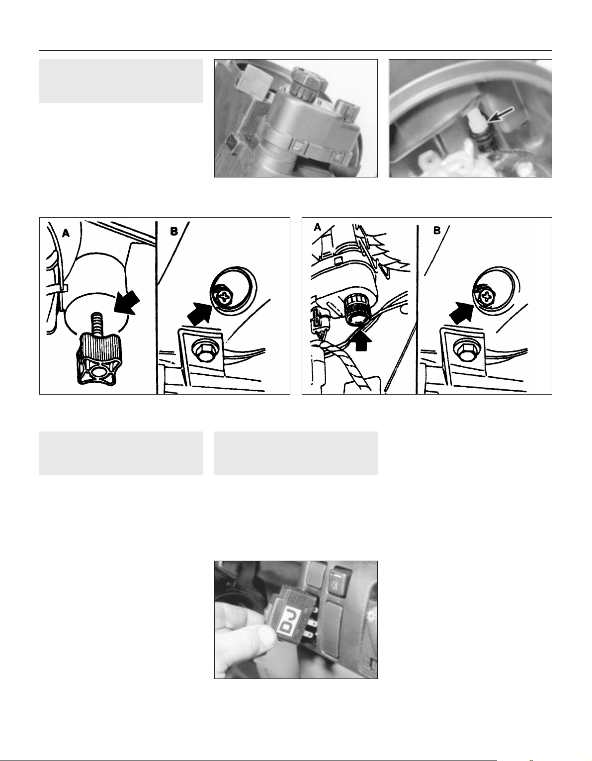
27 Headlamps - alignment
2
1 Correct alignment of the headlamp beams
is most important, not only to ensure good
vision for the driver, but also to protect other
drivers from being dazzled.
2 Accurate alignment should be carried out
using optical beam setting equipment.
3 In an emergency, adjustments may be
made by turning the adjustment screws
shown (see illustrations). If an adjustment is
made, the alignment should be checked using
beam setting equipment at the earliest
opportunity.
4 All 1992-on models are fitted with the
headlamp aim adjustment system, operated
through the facia-mounted switch (see
illustration).
a) Position ‘0’, is for correct alignment if just
the driving seat is occupied.
b) Position ‘1’, if all seats are occupied.
c) Position ‘2’, if all seats occupied and
luggage.
d) Position ‘3’, for just driver and luggage.
28 Headlamp dim-dip system -
general, removal and refitting
3
General
1 The system (where fitted) is governed by the
dim-dip control unit mounted either behind
and above the glovebox (early models), or
behind the main fuse panel (later models).
2 The control unit uses the oil pressure
warning lamp circuit to ensure that, when the
engine is running and the sidelamps are
switched on, reduced current is fed to the
headlamp dipped-beam circuits. This lights
the headlamps with approximately one-sixth
of their normal power so that the vehicle
cannot be driven using sidelamps alone.
3 To locate the dim-dip control unit, open the
main fuse panel covering flap and unclip it
from its bottom and top mountings (Section 3).
Then use a torch to see whether the unit is
fastened to the plastic bracket behind the facia
and fuse panel. The unit is usually rectangular,
of black plastic, and can be identified by the
colours of the five wires leading to it (see
applicable wiring diagram).
Removal
4 If the unit can be seen, remove the driver’s
side lower facia and footwell trim panels
(Chapter 11), then unscrew the four retaining
screws and lower the plastic bracket until the
control unit can be detached.
5 If the unit cannot be seen, remove the
glovebox assembly (Chapter 11). The unit will
be fastened to the underside of the facia top
surface.
Refitting
6 Refitting is the reverse of the removal
procedure.
26 Headlamp aim adjustment
motor - removal and refitting
3
Removal
1 Remove the headlamp, (Section 25).
2 Twist the motor clockwise to release it from
the headlamp, then carefully disconnect the
motor from the balljoint (see illustrations).
Refitting
3 Refitting is a reversal of removal, but ensure
that the motor is correctly engaged with the
balljoint.
12•10 Body electrical systems
26.2A Headlamp aim adjustment motor
(headlamp removed)
27.4 The headlamp aim adjustment switch
- 1992-on models
27.3B Headlamp alignment adjustment screws - models with
electric aim adjustment
A Vertical adjustment screw B Horizontal adjustment screw
27.3A Headlamp alignment adjustment screws - models without
electric aim adjustment
A Vertical adjustment screw B Horizontal adjustment screw
26.2B Headlamp aim adjuster balljoint
(arrowed)
Page 25
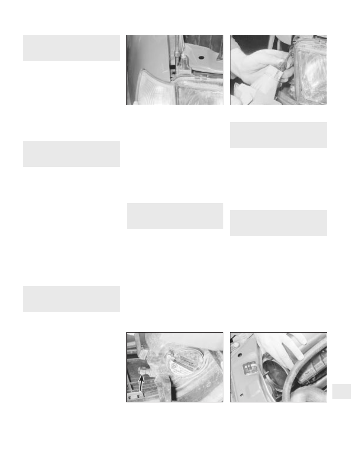
29 Front indicator lamp unit -
removal and refitting
2
Removal
1 Disconnect the battery negative lead.
2 Remove the single indicator lamp unit
securing screw, which is accessible through
the hole in the upper body panel (see
illustration).
3 Pull the lamp unit forwards to release it
from the body, then disconnect the wiring
plug (see illustration).
Refitting
4 Refitting is a reversal of removal.
30 Side repeater lamp - removal
and refitting
2
Removal
1 Disconnect the battery negative lead.
2 Remove the wheel arch liner, as described
in Chapter 11.
3 Working in the engine compartment,
disconnect the wiring plug, and detach the
earth lead from the body panel.
4 Working under the wheel arch, depress the
retaining tabs and manipulate the lamp
through the outside of the wing, pulling the
wiring and the grommet from the inner wing
panel.
5 The lens can be removed from the lamp by
twisting it to release the retaining clips.
6 Check the condition of the rubber sealing
ring, and renew if necessary.
Refitting
7 Refitting is a reversal of removal.
31 Front foglamp - removal,
refitting and adjustment
3
Removal
1 Disconnect the battery negative lead.
2 Removing (if necessary) the radiator grille
panel, as described in Chapter 11, disconnect
the appropriate foglamp wiring plug.
3 Apply the handbrake, jack up the front of
the vehicle and support it securely on axle
stands (see “Jacking and Vehicle Support”)
positioned under the body side members.
4 If removing the driver’s side foglamp,
remove the securing screws and withdraw the
plastic cover from the bumper/front wing to
expose the lamp mountings.
5 Unscrew the three securing bolts and
withdraw the lamp and wiring, the two bottom
bolts are obvious, but the third is well hidden
at the top of the lamp.
Refitting
6 Refitting is a reversal of removal, but on
completion check the foglamp adjustment.
Adjustment
7 The vertical aim of the foglamps can be
adjusted by turning the adjuster screw at the
rear of the lamp in the required direction. It will
be necessary to remove the plastic cover
(driver’s side only) from the bumper/front wing
to expose the adjuster screw (see
illustration).
32 Rear lamp unit - removal and
refitting
2
Removal
1 Disconnect the battery negative lead.
2 Working in the luggage compartment,
remove the cover from the rear of the lamp.
3 Release the top and bottom retaining clips,
and pull the bulbholder from the lamp.
Disconnect the wiring plug.
4 Remove the securing screws, and withdraw
the lamp unit from outside the vehicle.
5 Note that the lens cannot be renewed
separately, and if damaged, the complete
lamp unit must be renewed.
Refitting
6 Refitting is a reversal of removal.
33 Number plate lamp - removal
and refitting
2
Removal
1 Disconnect the battery negative lead.
2 Using a thin-bladed screwdriver, carefully
prise the lamp surround from the bumper.
3 Pull the lamp from the bumper, and
disconnect the wiring.
Refitting
4 Refitting is a reversal of removal.
34 Exterior lamp bulbs - renewal
1
Note: The glass envelopes of the headlamp
and foglamp bulbs must not be touched with
the fingers. If the glass is accidentally
touched, it should be washed with methylated
spirits and dried with a soft cloth. Failure to
observe this procedure may result in
premature bulb failure
1 Disconnect the battery negative lead.
Headlamps
Removal
2 Working in the engine compartment,
release the retaining clip, and remove the
cover from the rear of the headlamp (see
illustration).
Body electrical systems 12•11
31.7 Foglamp aim adjustment screw
(arrowed)
34.2 Removing the cover from the rear of
the headlamp
29.3 Disconnecting the front indicator
lamp unit wiring plug
29.2 Unscrewing the front indicator lamp
unit securing screw
12
Page 26
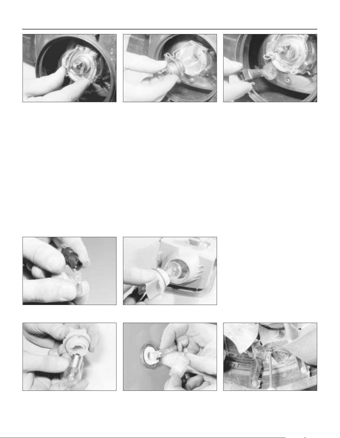
3 Pull the wiring plug from the base of the bulb,
then release the spring clip, grasp the bulb by
its contacts and carefully withdraw it (see
illustrations). Do not touch the bulb glass.
Refitting
4 Refitting is a reversal of removal.
Sidelamps
Removal
5 Working in the engine compartment,
release the retaining clip, and remove the
cover from the rear of the headlamp.
6 Pull the wiring plug from the bulbholder,
then pull the bulbholder from the headlamp
(see illustration).
7 The bulb is a push fit in the bulbholder (see
illustration).
Refitting
8 Refitting is a reversal of removal.
Front indicator lamp
Removal
9 Working in the engine compartment,
disconnect the wiring plug from the
bulbholder.
10 Twist the bulbholder anti-clockwise, and
pull it from the lamp unit (see illustration).
11 The bulb is a bayonet fit in the bulbholder
(see illustration).
Refitting
12 Refitting is a reversal of removal.
Front indicator side repeater
lamp
Removal
13 Twist the lamp lens anti-clockwise, and
pull it from the lamp.
14 The bulb is a push fit in the lamp (see
illustration).
Refitting
15 Refitting is a reversal of removal, but
ensure that the rubber sealing ring is correctly
seated between the lens and the body panel.
Front foglamp
Removal
16 To improve access, apply the handbrake,
jack up the front of the vehicle, and support
securely on axle stands (see “Jacking and
Vehicle Support”) positioned under the body
side members.
17 Remove the securing screws, and
withdraw the plastic cover (driver’s side only)
from the bumper/front wing to expose the
foglamp.
18 Remove the security screw, and withdraw
the cover from the base of the lamp (see
illustration).
19 Release the spring clip, using a
screwdriver if necessary, then grasp the bulb
by its contacts and carefully withdraw it. Do
not touch the bulb glass (see illustration).
20 Pull the wiring plug from the base of the
bulb.
Refitting
21 Refitting is a reversal of removal.
Rear lamp unit
Removal
22 Working in the luggage compartment,
remove the cover from the rear of the lamp.
23 Release the top and bottom retaining
clips, and pull the bulbholder from the lamp,
12•12 Body electrical systems
34.3A Release the spring clip . . . 34.6 Pull the sidelamp bulbholder from the
headlamp . . .
34.18 Removing a front foglamp cover
securing screw
34.10 Withdraw the front indicator lamp
bulbholder (lamp removed) . . .
34.07 . . . then pull the bulb from the
bulbholder
34.14 Removing a front indicator side
repeater lamp bulb
34.11 . . . then remove the bulb
34.3B . . . and withdraw the headlamp bulb
Page 27
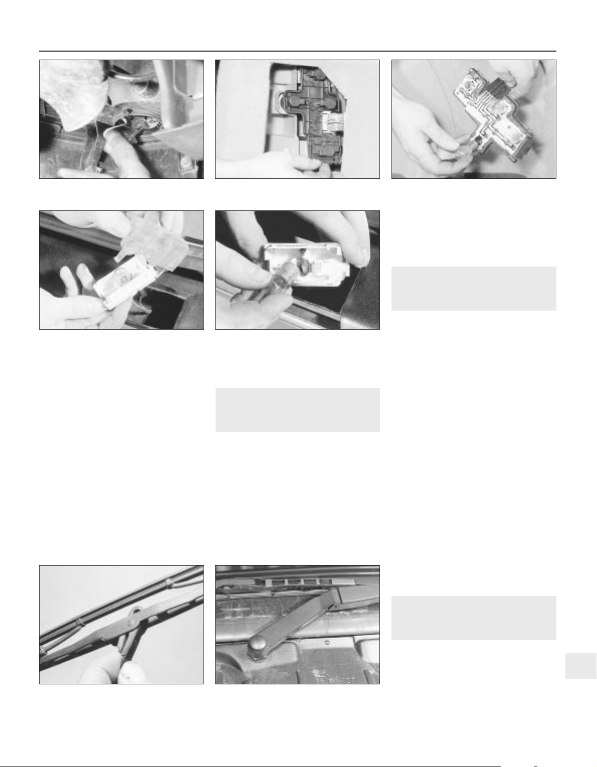
taking care not to strain the wiring (see
illustration).
24 The bulbs are a bayonet fit in the bulbholder
(see illustration). Note that the brake/tail lamp
bulb has offset bayonet pins so that it can only
be fitted in one position; ensure that the correct
type of replacement is obtained.
Refitting
25 Refitting is a reversal of removal.
Rear number plate lamp
Removal
26 Using a thin-bladed screwdriver, carefully
prise the lamp surround from the bumper.
27 Pull the lamp from the bumper, taking
care not to strain the wiring, and unclip the
lens (see illustration).
28 The bulb is a bayonet fit in the lamp (see
illustration).
Refitting
29 Refitting is a reversal of removal.
35 Wiper blades - renewal
1
Removal
1 The wiper blades should be renewed when
they no longer clean the glass effectively.
2 Lift the wiper arm away from the glass. On
some models it may be more convenient to do
this with the bonnet open.
3 With the blade at 90° to the arm, depress
the spring clip and slide the blade from the
hook (see illustration).
4 If necessary, extract the two metal inserts
and unhook the wiper rubber.
Refitting
5 Refitting is a reversal of removal, but where
applicable, make sure that the cut-outs in the
metal inserts securing the rubber to the blade
face each other.
36 Wiper arms - removal and
refitting
2
Windscreen and rear window
wipers
Removal
1 The wiper motor should be in its parked
position before removing the wiper arm. Mark
the position of the blade on the glass with
adhesive tape as a guide to refitting.
2 Lift the hinged covers, and remove the nuts
and washers securing the arms to the
spindles.
3 Prise the arms from the spindles, using a
screwdriver if necessary. Take care not to
damage the paintwork.
Refitting
4 Refitting is a reversal of removal. Note that
the passenger side wiper arm is longer than
that fitted to the driver’s side. Ensure that the
arms are fitted to their correct locations, as
incorrect installation can cause the blades to
foul one another when being used (see
illustration).
Headlamp wipers
5 The procedure is as described in
paragraphs 1 to 4, but the washer hose must
be disconnected from the stub on the body
panel.
37 Washer nozzles - removal
and refitting
1
Models up to 1990
Removal
1 To remove a nozzle, carefully prise it from
its location using a thin-bladed screwdriver.
Take care not to damage the paintwork.
Body electrical systems 12•13
34.24 . . . then remove the relevant bulb
36.4 Windscreen wiper arms 1992-on models
35.3 Removing a wiper blade
34.28 . . . then remove the bulb34.27 Unclip the lens from the rear
number plate lamp . . .
34.23 Release the rear lamp unit
bulbholder retaining clips . . .
34.19 Withdrawing a foglamp bulb
12
Page 28

2 Disconnect the washer hose and withdraw
the nozzle.
Refitting
3 To refit, reconnect the washer hose to the
nozzle, and push the nozzle into its locating
hole.
4 The nozzles can be adjusted by inserting a
pin into the jet, and swivelling it to the
required position.
1991-on models
5 The nozzles on all later models are fitted
with twin jets.
6 On some later models, the nozzles are
heated; the circuit is fed through fuse 29 and
is live whenever the ignition is switched on.
Current is regulated by a Positive
Temperature Coefficient (PTC) resistor that
takes outside temperature into account.
38 Windscreen wiper motor and
linkage - removal and refitting
3
Removal
1 Disconnect the battery negative lead.
2 Remove the wiper arms, as described in
Section 36.
3 Remove the windscreen cowl panel, as
described in Chapter 11.
4 Disconnect the wiring plug from the motor
(see illustration).
5 Unscrew the three bolts securing the
motor/linkage assembly to the body, then
withdraw the assembly (see illustrations).
6 If desired, the motor can be removed from
the linkage by unscrewing the three securing
bolts. Do not attempt to dismantle the linkage.
Refitting
7 Refitting is a reversal of removal.
39 Tailgate wiper motor -
removal and refitting
3
Removal
1 Disconnect the battery negative lead.
2 Remove the wiper arm, as described in
Section 36.
3 Extract the securing screws, and remove
the rear tailgate trim panel.
4 Disconnect the motor wiring plug.
5 Unscrew the two motor securing bolts,
noting the earth leads under the bolt heads
(see illustration).
6 Manipulate the motor assembly from the
tailgate.
Refitting
7 Refitting is a reversal of removal, ensuring
that the cut-out in the drive spindle rubber
seal engages with the notch in the drive
spindle (see illustration).
40 Headlamp wiper motor -
removal and refitting
3
Removal
1 Disconnect the battery negative lead.
2 Remove the wiper arm, as described in
Section 36.
3 Remove the headlamp, as described in
Section 25.
4 Disconnect the motor wiring plug.
5 Unscrew the two bolts securing the motor
mounting bracket to the body panel, then
withdraw the motor (see illustrations).
Refitting
6 Refitting is a reversal of removal.
12•14 Body electrical systems
38.4 Disconnecting the windscreen wiper
motor wiring plug
38.5B . . . then withdraw the assembly
40.5B . . . and withdraw the motor40.5A Unscrew the headlamp wiper motor
securing bolts . . .
39.7 Cut-out in tailgate wiper motor drive
spindle rubber seal must engage with
notch in drive spindle
39.5 Tailgate wiper motor assembly. Note
earth leads under heads of securing bolts
38.5A Unscrew the windscreen wiper
motor/linkage assembly securing bolts . .
Page 29
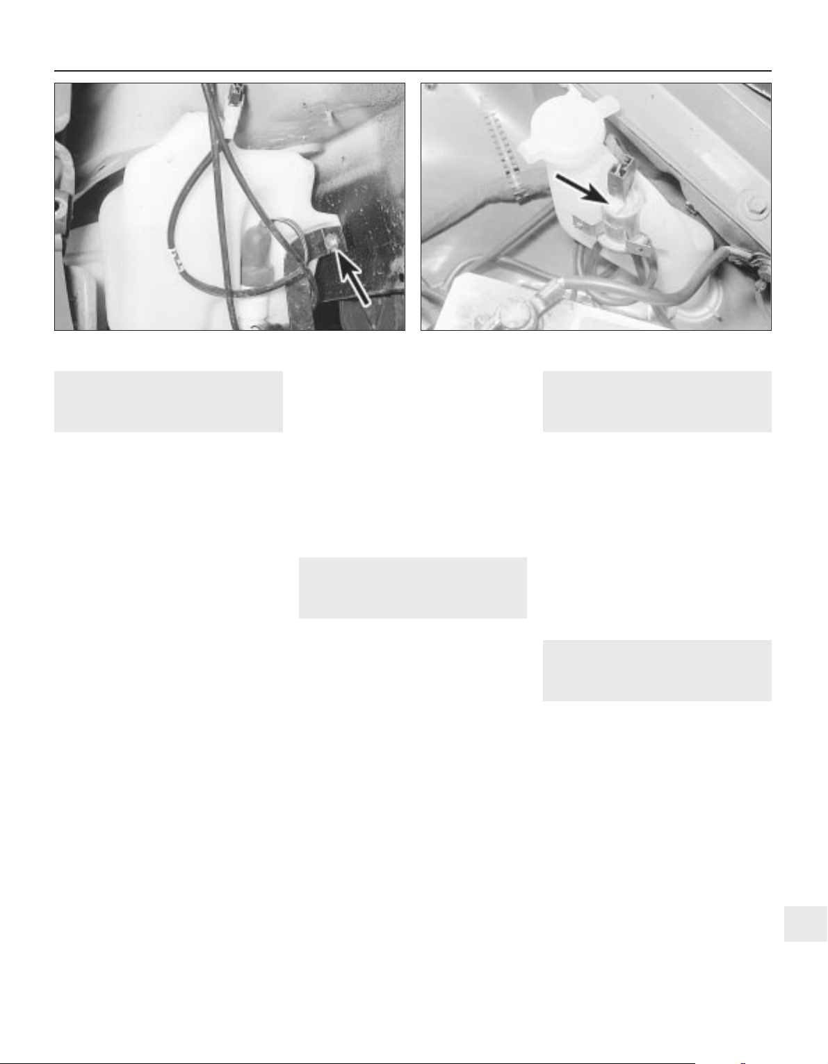
41 Washer fluid reservoir -
removal and refitting
2
1 Disconnect the battery negative lead.
Models without headlamp wash
Removal
2 Disconnect the wiring from the washer
pump.
3 Disconnect the washer fluid hose from the
pump. Be prepared for fluid spillage.
4 Remove the screw(s) securing the reservoir
to the body, and withdraw the reservoir.
Refitting
5 Refitting is a reversal of removal.
Models with headlamp wash
Removal
6 On models with headlamp wash, the
reservoir is in two sections, the upper section,
which can be removed from the engine
compartment, and the lower section, which
must be removed from under the wheel arch.
7 Disconnect the wiring from the headlamp
wash non-return valve in the top of the
reservoir.
8 Disconnect the washer fluid hoses from the
non-return valve. Be prepared for fluid spillage.
9 Remove the screw securing the upper
section of the reservoir to the wing panel.
10 Loosen the plastic collar securing the
upper section of the reservoir to the lower
section, then withdraw the upper section of
the reservoir from the engine compartment.
11 To remove the lower section of the
reservoir, continue as follows.
12 Apply the handbrake, then jack up the
front of the vehicle, and support on axle
stands (see “Jacking and Vehicle Support”)
positioned under the body side members.
13 Remove the securing screws, and
withdraw the plastic cover from the
bumper/front wing to expose the lower
section of the reservoir.
14 Remove the horns, (Section 22).
15 Remove the wheel arch liner, (Chapter 11).
16 Disconnect the wiring and the fluid hoses
from the washer pump. Be prepared for fluid
spillage.
17 Unscrew the bolts securing the
horn/reservoir support bracket and the
reservoir to the body, then withdraw the
bracket and the reservoir (see illustration).
Refitting
18 Refitting is a reversal of removal.
42 Washer pump - removal and
refitting
2
1 Disconnect the battery negative lead.
Models without headlamp wash
Removal
2 Disconnect the wiring and the fluid hose
from the pump. Be prepared for fluid spillage.
3 Pull the pump from the reservoir, being
prepared for fluid spillage if the reservoir still
contains fluid.
4 Examine the condition of the sealing
grommet, and renew if necessary, and clean the
gauze filter at the end of the pump pick-up tube.
Refitting
5 Refitting is a reversal of removal.
Models with headlamp wash
6 Apply the handbrake, then jack up the front
of the vehicle, and support on axle stands
positioned under the body side members.
7 Remove the securing screws, and withdraw
the plastic cover from the bumper/front wing
to expose the lower section of the fluid
reservoir.
8 Remove the wheel arch liner, (Chapter 11).
9 Proceed as described in paragraphs 2 to 5
inclusive.
43 Headlamp washer fluid
non-return valve - removal
and refitting
2
Removal
1 The valve is located on a bracket attached
to the upper section of the washer fluid
reservoir (see illustration).
2 Disconnect the battery negative lead.
3 Disconnect the wiring and the fluid hoses
from the valve. Be prepared for fluid spillage.
4 Remove the screw securing the valve
bracket to the reservoir, and withdraw the
valve.
Refitting
5 Refitting is a reversal of removal.
44 Electric window components
- removal and refitting
3
Note: Whenever any of the electric window
components are removed, after refitting the
components, the electric window controls
must be programmed, as described in
Section 45.
1 Disconnect the battery negative lead.
Rear door-mounted switches
Removal
2 Prise the plastic surround from the door
interior handle.
3 Carefully prise the switch from its location,
and disconnect the wiring plug.
Refitting
4 Refitting is a reversal of removal, but make
sure that the wiring is routed so that it does
not foul the electric window or lock operating
components.
Body electrical systems 12•15
43.1 Headlamp washer fluid non-return valve (arrowed)41.17 Horn/washer fluid reservoir support bracket securing bolt
(arrowed) - model with headlamp wash
12
Page 30
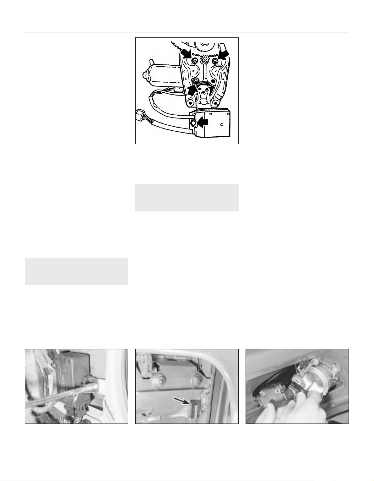
Centre console-mounted
switches
Removal
5 The switches must be removed as a
complete assembly, and cannot be
dismantled. If one of the switches is faulty, the
complete assembly must be renewed.
6 Remove the rear section of the centre
console, as described in Chapter 11.
7 Release the securing clips, and withdraw
the switch assembly through the top of the
centre console.
Refitting
8 Refitting is a reversal of removal.
Operating motors
9 Remove the door window regulator, as
described in Chapter 11.
10 To remove the motor assembly from the
front door window regulator, unscrew the
three motor securing nuts, and the single
screw securing the pulse pick-up unit to the
regulator assembly. Withdraw the motor,
complete with the pulse pick-up unit. Note
that if the motor or pick-up unit is/are faulty,
the two components must be renewed as an
assembly, as no spare parts are available (see
illustration).
11 The motor assembly fitted to the rear door
window regulator is an integral part of the
regulator, and no attempt should be made at
dismantling. If faulty, the complete
motor/regulator assembly must be renewed,
as no spares are available.
45 Electric window controls -
programming
1
1 Whenever the battery is disconnected, or any
of the electric window components are removed,
on completion of work, the electric window
controls must be programmed as follows.
2 Close all doors, and switch on the ignition.
3 Close one of the windows by pressing the
relevant operating switch. Press and hold the
switch for a further five seconds after the
relevant window has fully closed.
4 Repeat the procedure for the remaining
window(s).
46 Central door locking
components - removal and
refitting
3
1 Disconnect the battery negative lead.
Electronic control module
Removal
2 The module is mounted in the driver’s
footwell, behind the side trim panel.
3 Remove the driver’s footwell side trim
panel, as described in Chapter 11.
4 Unscrew the two securing nuts, and lift the
module from the body panel (see
illustration).
5 Depress the retaining clip to release the
wiring plug, then withdraw the module.
Refitting
6 Refitting is a reversal of removal.
Operating switch
Removal
7 The operating switch takes the form of a
microswitch, mounted inside the door at the
rear of the exterior handle assembly.
8 Remove the door inner trim panel, as
described in Chapter 11.
9 Peel back the plastic insulating sheet
sufficiently to gain access to the exterior
handle.
10 Unclip the microswitch from the rear edge
of the exterior handle assembly, and
disconnect the switch wiring plug from the
door wiring harness, then withdraw the switch
(see illustration).
Refitting
11 Refitting is a reversal of removal.
Door lock operating motor
Removal
12 Remove the door lock, as described in
Chapter 11.
13 Disconnect the lock operating rod from
the motor.
14 Remove the two securing screws, and
withdraw the motor from the lock assembly.
Refitting
15 Refitting is a reversal of removal.
Tailgate/boot lid lock operating
motor
Removal
16 On Hatchback models, extract the
securing screws and remove the rear tailgate
trim panel.
17 Remove the two securing screws, and
manipulate the motor to disconnect the lock
operating rod.
18 Withdraw the motor and disconnect the
wiring plug (see illustration).
Refitting
19 Refitting is a reversal of removal.
Fuel filler flap lock operating
motor
Removal
20 Remove the right-hand rear quarter trim
panels, as described in Chapter 11.
21 Disconnect the wiring plug from the rear
of the motor (see illustration).
12•16 Body electrical systems
44.10 Front door electric window motor
securing nuts and pulse pick-up securing
screw (arrowed)
46.10 Central door locking operating
microswitch (arrowed) in driver’s door
46.18 Disconnecting the wiring plug from
the tailgate lock operating motor -
Hatchback model
46.4 Unscrewing a central door locking
control module securing nut
Page 31

22 Unscrew the two screws securing the
motor to the mounting bracket, then
manipulate the motor to disconnect the lock
operating rod. Withdraw the motor.
Refitting
23 Refitting is a reversal of removal.
47 Aerial - removal and refitting
3
Removal
1 On models with an electric aerial,
disconnect the battery negative lead.
2 Remove the left-hand rear quarter trim
panel, as described in Chapter 11.
3 Remove the screw securing the earth
lead(s) to the body panel (see illustration).
4 Remove the screw securing the aerial
bracket to the body panel, then ensure that
the aerial is fully retracted, and pull it through
the grommet in the bodywork into the luggage
compartment. Disconnect the wiring plug on
models with an electric aerial, and disconnect
the aerial lead (see illustrations).
Refitting
5 Refitting is a reversal of removal, but ensure
that the rubber grommet is correctly seated in
the bodywork.
48 Aerial mast, electric -
removal and refitting
3
Removal
1 The mast on “factory fitted”, fully automatic
electric aerials, can be replaced separately.
2 Extend the aerial as far as possible, by
switching on the radio.
3 Unscrew the mounting nut.
4 Pull the sprung sleeve upwards and clear of
its base.
5 The assembly can now be removed from
the clutch mechanism, by pulling the
assembly upwards.
Refitting
6 Insert the ball end of the mast assembly
into the base.
7 Carefully push the mast assembly down as
far as possible, until it engages into the clutch
mechanism (see illustration).
8 Switch the radio off to retract the aerial.
9 If the aerial does not fully retract into its
base, guide the remaining mast into the base
by hand.
10 Insert the sprung sleeve into the base and
tighten the mounting nut.
11 Check the aerial works properly by turning
the radio on and off a few times.
49 Speakers - removal and
refitting
2
1 Disconnect the battery negative lead.
Facia-mounted speaker
Removal
2 Using a thin-bladed screwdriver, carefully
prise the speaker from the top of the facia
panel. Take care not to damage the facia trim
(see illustration)
3 Disconnect the wiring and withdraw the
speaker. If desired, the plastic trim panel can
be unclipped from the top of the speaker.
Refitting
4 Refitting is a reversal of removal.
Front door-mounted speaker
Removal
5 Remove the door inner trim panel, as
described in Chapter 11.
Body electrical systems 12•17
47.4A Unscrewing the radio aerial bracket
securing screws - electric aerial
49.2 Removing a facia-mounted speaker
(viewed through windscreen)
48.7 Push the mast assembly down, until it
engages in the clutch mechanism
47.4B Disconnecting the aerial lead electric aerial
47.3 Radio aerial earth lead securing
screw (arrowed) - electric aerial
46.21 Disconnecting the wiring plug from
the fuel filler flap operating motor -
Hatchback model
12
Always clean the aerial mast
in an upwards direction. This
should minimise dirt being
forced down, into the mast
sections.
Always clean the aerial mast
in an upwards direction. This
should minimise dirt being
forced down, into the mast
sections.
Page 32

6 Remove the three securing screws, and
withdraw the speaker from the door.
Disconnect the wiring plug (see illustration).
Refitting
7 Refitting is a reversal of removal, but note
that the speaker can only be fitted one way
up, so that the lug on the bottom of the
speaker rim engages with the corresponding
hole in the door skin.
Rear speaker - Hatchback
models
Removal
8 Remove the upper rear quarter trim panel,
as described in Chapter 11.
9 Remove the four securing screws, and
withdraw the speaker.
Refitting
10 Refitting is a reversal of removal.
Rear speaker Saloon models
Removal
11 Carefully prise the trim cover from the
parcel shelf, to expose the speaker.
12 Remove the four securing screws,
withdraw the speaker and disconnect the
wiring.
Refitting
13 Refitting is a reversal of removal.
50 Radio/cassette player -
removal and refitting
2
Removal
1 All the radio/cassette players fitted to the
Cavalier range have DIN standard fixings. Two
special tools, obtainable from in-car
entertainment specialists, are required for
removal.
2 Disconnect the battery negative lead.
3 Unscrew the four grub screws from the
corners of the radio cassette player, using an
Allen key or hexagon bit (see illustration).
4 Insert the tools into the holes exposed by
removal of the grub screws, and push them
until they snap into place. Pull the tools
outwards to release the unit (see illustration).
5 Pull the unit forwards, and withdraw it from
the facia.
Refitting
6 To refit the radio/cassette player, simply
push the unit into the facia until the retaining
lugs snap into place, then refit the grub
screws.
51 Sunroof motor - removal and
refitting
3
Removal
1 Ensure that the sunroof is fully closed.
2 Disconnect the battery negative lead.
3 Prise the courtesy lamp from the roof trim
panel, and disconnect the wiring.
4 Remove the two trim panel securing
screws, and withdraw the trim panel from the
roof, disconnecting the wiring from the
sunroof operating switch.
5 Disconnect the wiring plugs from the motor.
6 Unscrew the securing nut, and withdraw
the motor assembly.
Refitting
7 Refitting is a reversal of removal.
52 Speedometer cable - removal
and refitting
3
Removal
1 Remove the instrument panel, as described
in Section 18.
2 Pull the cable through the bulkhead into the
engine compartment, noting its routing.
3 Working in the engine compartment,
unscrew the securing sleeve and disconnect
the speedometer cable from the top of the
transmission (see illustration).
4 The cable can now be withdrawn from the
vehicle, noting its routing so that it can be
refitted in the same position.
Refitting
5 Refitting is a reversal of removal, ensuring
that the cable is correctly routed. Make sure
that the cable is not kinked or twisted
between the instrument panel and the
bulkhead as the instrument panel is refitted.
Note that the cable should be routed to the
right of the steering column support bracket.
12•18 Body electrical systems
49.6 Withdrawing a front door-mounted
speaker - wiring plug arrowed
50.4 . . . and withdraw the radio/cassette player using the special
tools
52.3 Speedometer cable securing sleeve (arrowed) at
transmission - SOHC model
50.3 Unscrew the grub screws . . .
Page 33

53 Anti-theft alarm - general
1 Certain models are fitted with an anti-theft
alarm as standard equipment.
2 The alarm system is triggered by door,
bonnet and boot lid/tailgate mounted
switches, and by ultrasonic sensors mounted
inside the passenger compartment (see
illustration).
3 The alarm features a self-diagnostic
function, and any faults should be referred to
a Vauxhall dealer, who will have access to the
necessary specialist diagnostic equipment.
54 Anti-theft alarm system
components - removal and
refitting
4
Control unit
Removal
1 Disconnect the battery negative lead.
2 Remove the driver’s side lower facia panel
as described in Chapter 11.
3 If necessary, remove the footwell side trim
panel as described in Chapter 11.
4 Undo the control unit retaining bolt,
disconnect the wiring plug and remove the
unit from its location.
Refitting
5 Refitting is a reversal of removal.
Ultrasonic sensor
6 Disconnect the battery negative lead.
7 Remove the centre body pillar trim panel as
described in Chapter 11.
8 Carefully release the ultrasonic sensor trim
panel and withdraw it downwards.
9 Release the ultrasonic sensor from its
location, disconnect the wiring plug and
remove the unit from the car.
Refitting
10 Refitting is a reversal of removal.
Bonnet contact unit
Removal
11 Disconnect the battery negative lead.
12 Using a screwdriver, depress the catch at
the base of the contact unit and withdraw the
contact from its location.
13 Disconnect the contact wiring and remove
the unit.
Refitting
14 Refitting is a reversal of removal.
55 Airbag - general
All 1993 Cavalier models are available with
an airbag that is designed to prevent serious
chest and head injuries to the driver during an
accident. A similar bag for the front seat
passenger is also available on certain models.
Sensors in the centre of the car measure the
vehicle deceleration rate and pass these
signals to a microprocessor. This unit
analyses the sensor data and compares the
information with pre-programmed values
stored in its memory, triggering the airbag if
the deceleration is severe. The airbag is
inflated in 50 milliseconds by a gas generator
that forces the bag out of the module cover in
the centre of the steering wheel.
No repairs are possible on the airbag unit or
its associated parts. The contents of the
following Sections are confined to removal
and refitting of the airbag, purely for access to
other non-related components.
Should a fault be suspected on the airbag
unit, indicated by the warning light on the
instrument panel, or if the car has been
involved in an accident, however minor,
consult a Vauxhall dealer immediately. Do not
attempt to dismantle any of the airbag
components or carry out any work
whatsoever, other than the procedures
described in the following Sections.
On vehicles fitted with a passenger side
airbag, do not fit accessories in the airbag
zone. Items like telephones, cassette storage
boxes, additional mirrors, etc., can be ripped off
and cause serious injury, if the airbag inflates.
Body electrical systems 12•19
12
53.2 Anti-theft alarm system component
locations
(Calibra model shown - component locations
identical on Cavalier)
1 Control unit
2 Ultrasonic sensor
with LED
3 Ultrasonic sensor
with probe
4 Radio contact
5 Bonnet contact unit
6 Horn
7 Relay
Warning: Before starting any
work on airbag or related
components, disconnect the
battery. Cover the battery’s
terminals and wait a minimum of 1
minutes as a precaution against
accidental firing of the airbag unit. This
period ensures that any stored energy in
the back-up capacitor is dissipated.
Handle the airbag unit with extreme care
as a precaution against personal injury,
and always hold it with the cover facing
away from the body. If in doubt
concerning any proposed work involving
the airbag unit or its control circuitry,
consult a Vauxhall dealer or other
qualified specialist.
Page 34

56 Airbag unit, drivers side -
removal and refitting
4
Note: On power steering models in particular,
it will be advantageous to jack up the front of
the car and support it on axle stands placed
under the body side members, so that the
steering wheel can be turned more easily.
Removal
1 Disconnect the battery negative lead and
cover the battery terminal. Wait a minimum of 1
minute.
2 With the steering wheel positioned in the
straight-ahead position, turn it 90° clockwise
so that the left-hand spoke is accessible from
the rear.
3 Using a Torx type socket, undo the first
airbag retaining bolt from the rear of the
steering wheel (see illustration).
4 Turn the steering wheel 180° anti-clockwise
so that the right-hand spoke is accessible
from the rear.
5 Undo the second retaining bolt from the
rear of the steering wheel.
6 Return the steering wheel to the
straight-ahead position then carefully lift up
the airbag unit.
7 Disconnect the wiring plug and remove the
airbag from the car.
Refitting
8 Refitting is a reversal of removal.
57 Steering wheel (with airbag)
- removal and refitting
4
Note: Read warning at the beginning of
Section 55, before starting work. A
two-legged puller will be required for this
operation. Note also that the steering wheel is
a very tight fit on the shaft.
Removal
1 Remove the airbag unit as described
previously.
2 Ensure that the steering wheel is in the
straight ahead position.
3 From the centre of the steering wheel
unscrew the two screws securing the airbag
contact unit.
4 Using a screwdriver, prise back the tabs on
the lockwasher securing the steering wheel
retaining nut.
5 Unscrew and remove the steering wheel
retaining nut and the lockwasher.
6 Make alignment marks between the
steering wheel and the end of the column
shaft.
7 A suitably small two-legged puller must
now be fitted to the steering wheel in order to
pull it from the column shaft.
8 Once the steering wheel has been released
from the column shaft, disconnect the horn
wiring and remove the steering wheel.
Refitting
9 Begin refitting by positioning the steering
wheel on the column shaft, ensuring that the
marks made on removal are aligned, and that
the wheel correctly engages with the airbag
contact unit. It may be necessary to tap the
steering wheel fully home on the column shaft
using a metal tube and socket.
10 Reconnect the horn wiring.
11 Refit the lockwasher and the steering
wheel retaining nut, and tighten the nut to the
specified torque. Bend up the lockwasher to
secure.
12 Refit the two screws securing the airbag
contact unit.
13 Refit the airbag as described previously.
58 Airbag contact unit - removal
and refitting
4
Note: Read warning at the beginning of
Section 55, before starting work.
Removal
1 Remove the airbag and the steering wheel
as described previously.
2 Remove the steering column upper and
lower shrouds, referring to Chapter 10, if
necessary.
3 Disconnect the contact unit wiring plug
below the steering column and withdraw the
contact unit from the column, noting its fitted
position as a guide to reassembly (see
illustration).
Refitting
4 Before refitting the contact unit, ensure that
the front wheels are in the straight-ahead
position.
5 Place the contact unit on the column in the
correct position as noted during removal.
6 Route the wiring harness under the steering
column lock/ignition switch and connect the
wiring plug.
7 Refit the steering column shrouds.
8 Refit the steering wheel and airbag as
described previously.
59 Airbag unit, passengers side
- removal and refitting
4
Note: Read warning at the beginning of
Section 55, before starting work.
Removal
1 Disconnect the battery, cover the terminals
and wait at least 1 minute.
2 Remove the glovebox assembly. Refer to
Chapter 11, for further details if necessary.
3 Remove the right hand ventilation air duct.
12•20 Body electrical systems
58.3 Airbag contact unit retaining screws
56.3 Airbag, steering wheel and contact unit details
Warning: Read warning at the
beginning of Section 55, before
starting work.
Warning: Stand the unit with the
cover uppermost and do not
expose it to heat sources in
excess of 100ºC. Do not attempt
to open or repair the airbag unit, or apply
any voltage to it. Do not use any airbag
unit that is visibly damaged or has been
tampered with.
Page 35

4 Disconnect the plug connections.
5 Unbolt the six M6 nuts from the two side
brackets.
6 Remove the airbag unit (see illustration).
Refitting
4 Refitting is a reversal of removal.
60 Bracket, passenger airbag
unit - removal and refitting
5
Note: Read warning at the beginning of
Section 55, before starting work. This process
involves removal of the windscreen, refer to
Chapter 11, before starting work.
Removal
1 Remove the passenger side airbag unit as
described in Section 59.
2 Remove the airbag unit cover.
3 Remove the water deflector from in front of
the windscreen.
4 Remove the windscreen.
5 The brackets can now be unbolted.
Refitting
4 Refitting is a reversal of removal.
61 Airbag control unit - removal
and refitting
4
Note: Read warning at the beginning of
Section 55, before starting work.
Removal
1 Disconnect the battery negative lead and
cover the battery terminal to prevent
accidental reconnection.
2 Remove the centre console rear section as
described in Chapter 11.
3 Disconnect the control unit wiring plug,
then undo the three nuts and remove the unit
from the car (see illustration).
Refitting
4 Refitting is a reversal of removal.
62 Wiring diagrams - general
1 The wiring diagrams are of the current flow
type, each circuit being shown in the simplest
possible fashion. Note that since the diagrams
were originally written in German (to the DIN
standard), all wire colours and abbreviations
used on the diagrams themselves are in
German. Refer to the information given
overleaf for clarification.
2 The bottom line of the diagram represents
the “earth” or negative connection; the
numbers below this line are track numbers,
enabling circuits and components to be
located using the key.
3 The lines at the top of the diagram
represent “live feed” or positive connection
points. The line marked “30” is live at all
times, that marked “15” is live only when the
ignition is switched on.
4 Numbers on the diagram that are framed in
square boxes at the end of a wire show the
track reference number in which that wire is
continued. At the point indicated will be
another framed number referring back to the
circuit just left.
5 As an example of how to use the diagrams,
trace with the help of the following text the
reversing lamp switch circuit located between
track reference numbers 496 and 498 on the
1991 model year diagram on page 12•40.
6 Starting at the top of track 497, the supply
for the circuit comes from the line “15”,
showing that the circuit is fed only when the
ignition is switched on, through fuse 22 (F22,
rated at 10 amps). Note that this fuse can also
protect the feed for several other circuits,
some of which may not be applicable to the
vehicle being worked on.
7 If the vehicle in question has a manual
transmission (MT), the circuit continues along
a black wire of 0.75 mm cross-section (as
shown by “SW 0.75” in the wire path), through
terminal 12 of connector X5 to the reversing
lamp switch S7. From the switch the circuit
continues along a white wire, with a black
tracer and of 0.75 mm cross-section (WSSW
0.75), through terminal 2 of connector X5 and
terminal 1 of connector X6, to the reversing
lamp bulbs (E17 and E18). The circuit is
completed by a brown wire from each
bulbholder to earth; in this case the “earth”
wire simply attaches the component to the
nearest piece of metal bodywork, but in other
cases earthing is achieved by the component
mounting and no wire is needed. The diagram
shows, as simply as possible, that when the
switch contacts (which are normally open) are
closed by the driver selecting reverse gear,
current is allowed to flow to earth through the
switch and bulbs causing the reversing lamps
to light.
8 If the vehicle in question has automatic
transmission (AT), the circuit differs in that the
“live feed” goes from fuse 22 to terminal “F” of
the transmission selector lever position switch
connector X46 (track reference number 773).
When position “R” is selected, terminals “F”
and “G” are connected so that the circuit feed
continues (back to track reference number
496, the “RFS/reversing lamp” circuit) along
the same route described above for manual
transmission models.
Body electrical systems 12•21
61.3 Airbag control unit details59.6 Removing the passenger side airbag
12
Page 36

12•22 Body electrical systems
Explanations of abbreviations used in wiring diagrams
ABS Anti-lock braking system
AC Air conditioning
AZV Trailer hitch
AT Automatic transmission
ATC Automatic temperature control
BR Trip (on-board) computer
CC Check control system
CRC Cruise control
D Diesel
DS Theft protection
DT Turbo Diesel
DWA Anti-theft warning system
DZM Tachometer
EFC Electric folding roof (Convertible)
EKS Pinch guard (electric windows)
EMP Radio
EUR Euronorm (emission control standard)
engine
EZ + El Plus ignition system (with self-
diagnosis)
EZV Ecotronic
FH Electric windows
GB Great Britain
HS Heated rear window
HW Rear window wiper
HZG Heating
HRL Luggage compartment lamp
INS Instrument panel
IRL Courtesy lamps
KAT Catalytic converter
KBS Wiring harness
KV Contact breaker distributor
L3.1 Bosch Jetronic fuel injection system
LCD Liquid crystal display (LCD)
instruments
LHD Left-hand drive
4WD Four-wheel-drive
LWR Headlamp aim adjustment
M1.5 Bosch Motronic M1.5 engine
management system
M2.5 Bosch Motronic M2.5 engine
management system
MOT Motronic (general)
MT Manual gearbox
MUL Multec fuel injection system
N Norway
NS Front foglamps
NSL Rear foglamps
OEL Oil level/pressure check system
OPT Optional equipment
PBSL Park and brake shift block
(automatic transmission, selector
lever in position ‘P’)
P/N Park/neutral (automatic transmission)
POT Potentiometer
RC Rear suspension level control
system
RFS Reversing lamps
RHD Right-hand drive
S Sweden
SD Sunroof
SH Heated seats
SRA Headlamp washers and wipers
TANK Fuel level sender unit
TD Turbo Diesel
TEMP Temperature gauge
TFL Daytime driving lamps
TKS Courtesy lamp (door pillar) switches
TSZI Transistorised ignition (inductive-
triggered) system
VGS Carburettor
WEG Odometer frequency/roadspeed
sensor
WHR Rear suspension level control
system
WS Warning buzzer
ZV Central locking
ZYL Cylinder
Colour codes
BL Blue
HBL Light blue
BR Brown
GE Yellow
GR Grey
GN Green
RT Red
WS White
SW Black
LI Lilac
VI Violet
Wiring identification
Example: GEWS 1.5
GE - Wire basic colour
WS - Wire tracer colour
1.5 - Wire cross-section in mm
2
Note: Not all items shown are fitted to all models. Refer to Section 62 (Chapter 12) for details of diagram usage.
Page 37

Wiring diagrams 12•23
12
Key to wiring diagrams for 1989 models
E1 Sidelamp - left 406
E2 Tail lamp - left 302, 380, 407
E3 Number plate lamp 413
E4 Side lamp right 409
E5 Tail lamp right 382, 410
E6 Engine compartment lamp 416
E7 Headlamp main beam - left 437
E8 Headlampmain beam - right 438
E9 Headlampdipped beam - left 384, 439
E10 Headlamp dipped beam - right 386, 440
E11 Instrument illumination lamps 328 to 329
E12 Gear selector lever illumination lamp (automatics) 799
E13 Luggage compartment lamp 485
E14 Courtesy lamp 487
E15 Glovebox lamp 599
E16 Cigarette lighter illumination lamp 598
E17 Reversing lamp - left 497
E18 Reversing lamp - right 498
E19 Heated rearwindow 572
E20 Front foglamp - left 448
E21 Front foglamp - right 447
E24 Rear foglamp - left 454
E25 Seat heater - front left 575
E30 Seat heater - front right 579
E32 Clock illumination lamp 552
E38 Trip computer illumination lamp 539
E39 Rear foglamp - right 455
E41 Courtesy lamp (with delay) 488 to 490
E50 Kerb lamp - driver’s door 635
E51 Kerb lamp - passenger door 653
F1 to Fuse (in fusebox) Various
F30
F32 Fuse - mixture preheating (not UK) 232
F33 Fuse - electronic carburettor (not UK) 201
F34 Fuse (in relay box, engine compartment) 834
F35 Voltage stabiliser 302
F36 Fuse - fuel filter heating (Diesel models) 866
G1 Battery 101
G2 Alternator 110
G3 Battery - Diesel models 846
G6 Alternator - Diesel models 850 to 852
H2 Horn 591
H3 Direction indicator warning lamp 318, 320
H4 Oil pressure warning lamp 310
H5 Brake fluid level warning lamp 313
H6 Hazard warning flasher warning lamp 470
H7 Alternator charge warning lamp 310
H8 Headlamp main beam warning lamp 322
H9 Brake lamp - left 388
H10 Brake lamp - right 390
H11 Direction indicator lamp - front left 472
H12 Direction indicatorlamp - rear left 473
H13 Direction indicator lamp - front right 481
H14 Direction indicator lamp - rear right 482
H16 Glow plug warning lamp (Diesel models) 323
H17 Trailer direction indicator warning lamp 321
H18 Horns (twin) 592, 593
H19 Headlamps-on warning buzzer 494, 495
H21 Handbrake-on warning lamp 315
H23 Radio/cassette player 585, 586
H25 Door mirror heater warning lamp 678
H26 ABS warning lamp 319
H30 Engine fault warning lamp 324
H33 Direction indicator side repeater lamp - left 476
H34 Direction indicator side repeater lamp - right 478
H42 Automatic transmission warning lamp 325
H45 Four-wheel-drive warning lamp 327
H46 Catalytic converter temperature warning lamp (not UK) 329
K1 Relay-heated rear window 571 to 572
K5 Relay - front foglamps 448 to 450
K6 Relay - air conditioning (not UK) 801 to 802
K7 Relay - air conditioning blower (not UK) 808 to 809
K8 Relay - intermittent windscreen wipe 503 to 506
K9 Relay - headlamp wash 522 to 523
K10 Relay - direction indicator/hazard warning flashers 467 to 469
K20 HEI ignition control unit 122 to 124
K25 Relay - glow plugs (Diesel models) 856 to 859
K30 Relay - intermittent rear window wipe 515 to 517
K35 Relay - door mirror heater 683 to 685
K37 Central locking control unit 606 to 612
K45 Relay - mixture preheating (not UK) 231 to 232
K47 Relay - surge arrester (ABS) 702 to 703
K50 ABS control unit 707 to 721
K51 Relay - cooling fan 830 to 831
K54 Electronic carburettor control unit (not UK) 203 to 226
K55 Relay - electronic carburettor (not UK) 203 to 206
K57 Fuel injection control unit (not UK) 139 to 161
K58 Relay - fuel pump (not UK) 162 to 163
K59 Relay - daytime running lamps (not UK) 420 to 426
K61 Motronic M4.1 control unit 170 to 194
K62 Dim-dip control unit 428 to 432
K63 Relay - horn 593 to 594
K64 Relay - air conditioning blower (not UK) 802 to 803
K67 Relay - cooling fan 827 to 828
K68 Relay - fuel injection system 294 to 299, 196 to 199
K69 Motronic M2.5 control unit 267 to 297
K71 Ride control unit (not UK) 739 to 754
K80 Relay - fuel filter heater (Diesel models) 865 to 866
K82 Relay - engine revolution 862 to 863
K83 Four-wheel-drive control unit 725 to 731
No Description Track No Description Track
Page 38

12•24 Wiring diagrams
K84 MSTS ignition control unit 247 to 256
K85 Automatic transmission control unit 771 to 797
K86 Check control unit 370 to 392
K87 Relay - auxiliary cooling fan 833 to 834
K88 Catalytic converter temperature control unit (not UK) 760 to 762
K89 Relay - rear fog lamps 444 to 447
K90 Relay - air conditioning compressor (not UK) 820 to 821
K93 Relay - air conditioning compressor (not UK) 821 to 822
L1 Ignition coil 121 to 122, 133 to 134, 174 to 175,
225 to 226, 243 to 244, 261 to 262
M1 Starter motor 105 to 106
M2 Windscreen wiper motor 501 to 504
M4 Cooling fan motor 113
M6 Headlamp wiper motor - left 525 to 527
M7 Headlamp wiper motor - right 529 to 531
M8 Rear window wiper motor 513 to 515
M13 Sunroof motor 692 to 694
M18 Central locking motor - driver’s door 607 to 610
M19 Central locking motor - left rear door 622 to 624
M20 Central locking motor - right rear door 626 to 628
M21 Fuel pump 163, 196, 299
M26 Electric aerial motor 584 to 585
M30 Door mirror motor and heater - driver’s door 674 to 676
M31 Door mirror motor and heater - passenger door 680 to 682
M32 Central locking motor - passengerdoor 614to617
M33 Idle speed adjuster 146 to 149, 183 to 184, 277 to 278
M37 Central locking motor - boot lid/tailgate 618 to 621
M39 Headlamp aim adjustment motor - left 557 to 560
M40 Headlamp aim adjustment motor - right 561 to 564
M41 Central locking motor - fuel filler flap 623 to 625
M43 Ride control actuator - front left (not UK) 739 to 741
M44 Ride control actuator - front right (not UK) 743 to 745
M45 Ride control actuator - rear left (not UK) 747 to 749
M46 Ride control actuator - rear right (not UK) 751 to 753
M47 Electric window motor - front left 636 to 640
M48 Electric window motor - front right 654 to 658
M49 Electric window motor - rear left 642 to 646
M50 Electric window motor - rear right 660 to 664
M55 Washer fluid pump 518 to 519
P1 Fuel gauge 304
P2 Coolant temperature gauge 306
P3 Clock 551
P4 Fuel level sender unit 304
P5 Coolant temperature sensor 306
P7 Tachometer 308
P8 Oil pressure gauge 341
P9 Voltmeter 339
P10 Oil pressure sensor 341
P11 Airflow meter (Motronic M4.1) 185 to 189
P12 Coolant temperature sensor 178, 272
P13 Trip computer outside air temperature sensor 542 to 543
P14 Distance sensor (not UK) 336 to 337
P17 ABS wheel sensor - front left 707
P18 ABS wheel sensor - front right 710
P19 ABS wheel sensor - rear left 712
P20 ABS wheel sensor - rear right 714
P21 Speedometer frequency sensor (not UK) 332
P23 Pressure sensor 249 to 250
P24 Oil temperature sensor 251
P24 Automatic transmission fluid temperature sensor 795
P27 Brake pad wear sensor - front left 375
P28 Brake pad wear sensor - front right 375
P29 Inlet manifold temperature sensor (not UK) 207 to 208
P30 Coolant temperature sensor 209 to 210, 150
P31 Throttle position sensor (not UK) 209 to 211
P32 Oxygen sensor - heated (not UK) 193 to 194, 291 to 292
P33 Oxygen sensor 157
P34 Throttle position sensor 158 to 160, 780
P35 Crankshaft speed/position sensor 189 to 191, 223 to 225,
281 to 282
P39 Trailer bulb failure sensor 392 to 394
P43 Electronic speedometer 336
P44 Air mass meter (Motronic M2.5) 294 to 296
P45 Automatic transmission input speed sensor 787 to 788
P46 Knock sensor 284 to 285
P47 Distributor ‘Hall-effect’ sensor (Motronic M2.5) 287 to 288
P48 Automatic transmission distance sensor 785 to 786
P50 Catalytic converter temperature sensor (not UK) 761 to 762
R2 Carburettor preheating 116, 228
R3 Cigarette lighter 596 to 597
R5 Glow plugs (Diesel models) 858 to 859
R7 Mixture preheating (not UK) 232
R12 Automatic choke 117
R15 Mixture adjustment potentiometer (not UK) 155 to 157
R19 Cooling fan motor resistor 828, 848
S1 Ignition switch 102 to 106, 851 to 852
S2.1 Lighting switch 404 to 407
S2.2 Courtesy lamp switch 487
S2.3 Instrument illumination lamp dimmer 328
S3 Heater blower switch 837 to 844
S4 Heated rear window switch 570 to 571
S5.2 Dipped beam switch 438, 439
S5.3 Direction indicator switch 480 to 482
S5.4 Sidelamp switch 401 to 402
S7 Reversing lamp switch 497
S8 Brake lamp switch 462
S9.2 Windscreen wiper switch 501 to 504
S9.5 Rear window wash/wiper switch 516 to 518
S10 Automatic transmission switch 770 to 776
S11 Brake fluid level warning sensor 313
S13 Handbrake-on warning switch 315
S14 Oil pressure switch 310
S15 Luggage compartment lamp switch 485
S17 Passenger door courtesy lamp switch 490
Key to wiring diagrams for 1989 models (continued)
No Description Track No Description Track
Page 39

Wiring diagrams 12•25
12
Key to wiring diagrams for 1989 models (continued)
S21 Front foglamp switch 450 to 452
S22 Rear foglamp switch 455 to 457
S27 Air conditioning compressor low-pressure switch (not UK) 821
S28 Air conditioning compressor high-pressure switch (not UK) 821
S29 Cooling fan switch 113
S30 Seat heater switch - front left 575 to 577
S31 Rear door courtesy lamp switch - left 491
S32 Rear door courtesy lamp switch - right 492
S35 Sunroof travel microswitch 692
S36 Sunroof travel microswitch 694
S37 Electric windows switch assembly 637 to 663
S37.1 Electric window switch - front left 637 to 639
S37.2 Electric window switch - front right 655 to 657
S37.3 Electric window switch - rear left 643 to 645
S37.4 Electric window switch - rear right 661 to 663
S37.5 Electric windows safety cut-out switch 641 to 642
S37.6 Electric windows anti-jam switch 659
S37.7 Electric windows automatic control 646 to 651
S39 Electric windows switch - rear left door 647 to 649
S40 Electric windows switch - rear right door 665 to 667
S41 Central locking switch driver’sdoor 601 to 603
S42 Central locking switch passenger door 605
S44 Throttle position sensor 173 to 174, 278 to 279
S47 Driver’s door courtesy lamp switch 493 to 494
S51 Cooling fan switch (not UK models) 825 to 827
S52 Hazard warning flasher switch 469 to 474
S55 Seat heater switch - front right 579 to 581
S57 Sunroof switch 690 to 696
S63.1 Trip computer function reset switch 543
S63.2 Trip computer clock hours adjustment switch 544
S63.3 Trip computer function select switch 545
S63.5 Trip computer clock minutes adjustment switch 546
S64 Horn switch 591 to 594
S68.1 Door mirror adjustment switch 672 to 677
S68.2 Door mirror heater switch 679 to 680
S68.3 Door mirror left/right selector switch 673 to 677
S76 Air conditioning compressor switch - high-pressure,
cooling fan (not UK) 832
S82 Washer pump switch 371
S91 Oil pressure switch (not UK models) 165 to 166
S93 Coolant level sensor 372
S95 Oil level sensor 373
S98 Headlamp aim adjustment switch 556 to 558
S99 Electric windows switch - driver’s door 634
S100 Electric windows switch - passenger door 652
S104 Kickdown switch (automatics) 792
S105 Start-up assistance switch (automatics) 796 to 798
S106 Economy/power programme switch (automatics) 791
S107 Throttle position sensor 771 to 776
S108 Cooling fan switch (Diesel models) 847 to 848
S109 Air conditioning compressor switch (not UK) 817
S110 Ride control switch (not UK) 738 to 743
S115 Automatic transmission fluid temperature sensor 793
S116 Brake lamp switch 464 to 465
S117 Four-wheel-drive hydraulic pressure switch 729
S118 Air conditioning refrigerant temperature switch (not UK) 829
U2 Trip computer 538 to 548
U4 ABS hydraulic modulator assembly 705 to 718
U4.1 ABS hydraulic pump relay 706 to 709
U4.2 ABS solenoid valves relay 715 to 718
U4.3 ABS hydraulic pump 705
U4.4 ABS diode 717
U4.5 ABS solenoid valve - front left 710
U4.6 ABS solenoid valve - front right 711
U4.7 ABS solenoid valve - rear left 712
U4.8 ABS solenoid valve - rear right 713
U5.1 Check control tail lamp and dipped beam bulb failure
warning lamp 362
U5.2 Check control brake lamp bulb failure warning lamp 363
U5.3 Check control coolant oil level warning lamp 360
U5.5 Check control brake pad wear warning lamp 364
U5.6 Check control washer fluid level warning lamp 359
U5.7 Check control coolant level warning lamp 361
U7 Air conditioning control unit (not UK) 806 to 824
U7.6 Air conditioning blower switch (not UK) 806 to 811
U7.8 Air conditioning switch (not UK) 813 to 824
U12.1Temperature switch (Diesel models) 865
U12.2Fuel filter heater (Diesel models) 866
U13.1Automatic transmission solenoid valve - shift 1 784
U13.2Automatic transmission solenoid valve - shift 2 785
U13.3Automatic transmission solenoid valve - lock-up control 786
U13.4Automatic transmission solenoid valve - pressure control 787
V1 Brake fluid level warning lamp test diode (not UK) 312
V8 Air conditioning compressor diode (not UK) 820
X1 Trailer electrical socket 453 ,458 to 460
X2 Accessory electrical connectors 587
X5 to Wiring connectors Various
X62
Y1 Air conditioning compressor clutch (not UK) 821
Y4 Headlamp washer solenoid valve 523
Y5 Fuel solenoid valve (Diesel models) 860
Y7 Fuel injectors 186 to 193, 280 to 287
Y10 Distributor (Hall-effect) 249 to 253
Y23 Distributor (Inductive discharge) 123 to 127
Y24 Distributor (Inductive discharge) (not UK) 129 to 136
Y26 Throttle valve positioner (not UK) 201 to 207
Y27 Pre-throttle valve (not UK) 218 to 219
Y30 Cold start valve (Diesel models) 863
Y32 Fuel injector (not UK) 140
Y33 Distributor 170, 262
Y34 Fuel tank ventilation valve (not UK) 198, 292
Y43 Air conditioning vacuum control (not UK) 815 to 818
Y44 Four-wheel-drive solenoid valve 731
No Description Track No Description Track
Page 40

12•26 Wiring diagrams
Wiring diagram for 1989 models
Page 41

Wiring diagrams 12•27
12
Wiring diagram for 1989 models (continued)
Page 42

12•28 Wiring diagrams
Wiring diagram for 1989 models (continued)
Page 43

Wiring diagrams 12•29
12
Wiring diagram for 1989 models (continued)
Page 44

12•30 Wiring diagrams
Wiring diagram for 1989 models (continued)
Page 45

Wiring diagrams 12•31
12
Wiring diagram for 1989 models (continued)
Page 46

12•32 Wiring diagrams
Wiring diagram for 1989 models (continued)
Page 47

Wiring diagrams 12•33
12
Wiring diagram for 1989 models (continued)
Page 48

12•34 Wiring diagrams
Wiring diagram for 1989 models (continued)
Page 49

Wiring diagrams 12•35
12
Wiring diagram for 1989 models (continued)
Page 50

12•36 Wiring diagrams
Wiring diagram for 1989 models (continued)
Page 51
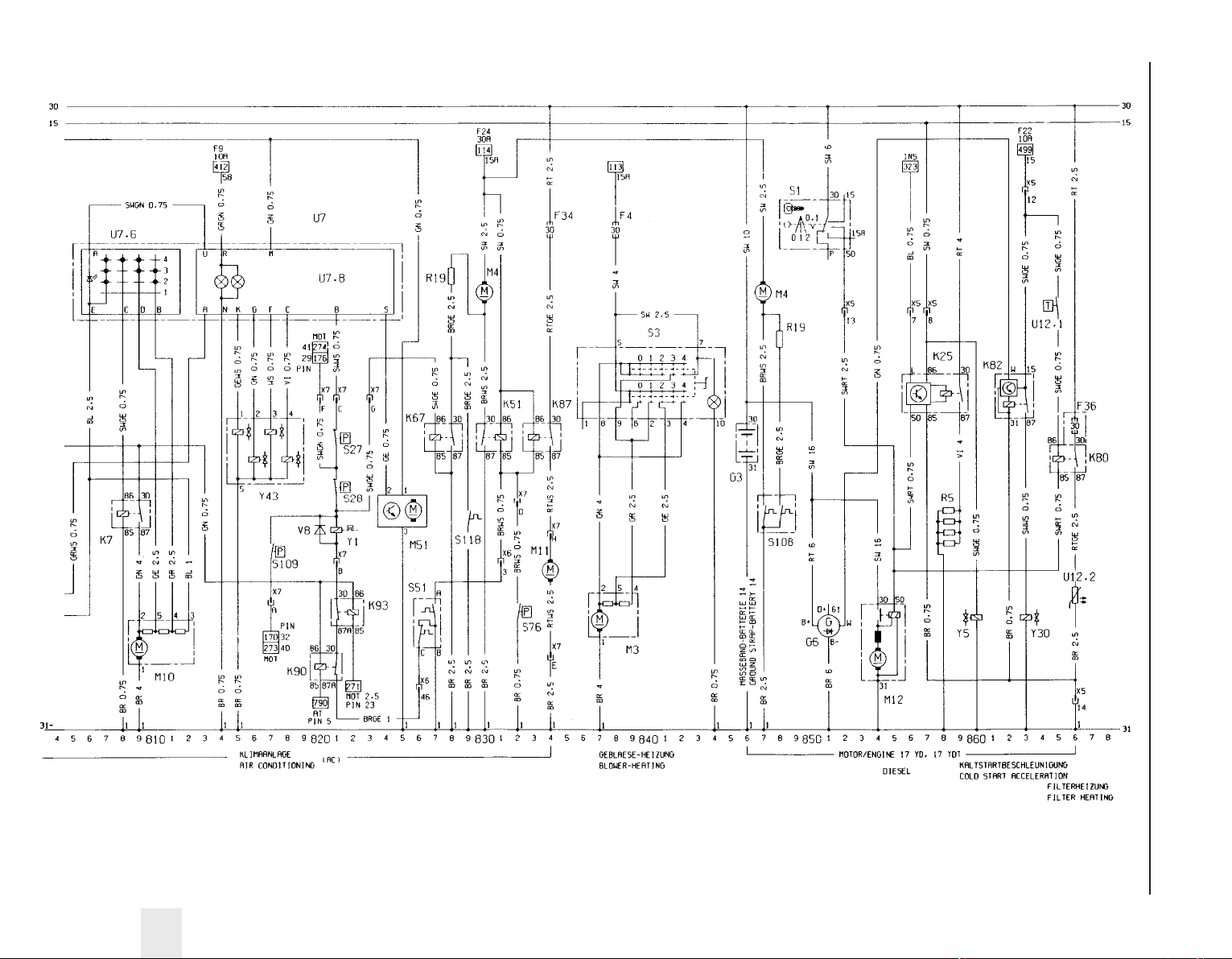
Wiring diagrams 12•37
12
Wiring diagram for 1989 models (continued)
Page 52

12•38 Wiring diagrams
Key to wiring diagrams for 1991 models
No Description Track No Description Track
Wiring diagrams for 1991 models
Location of applicable circuits Track Location of applicable circuits Track
Air conditioning system 800 to 850
Alternator 111
Anti-lock braking system (ABS) 701 to 722
Anti-theft alarm system 633 to 647
Automatic transmission control system 773 to 799
Battery 100
Brake lamps 461 to 462
Carburettor 118 to 121
Central locking system 600 to 627
Check control system 347 to 371
Cigarette lighter 597 to 598
Clock 661 to 663
Courtesy lamps - front 487 to 494
Courtesy lamps - rear 569 to 573
Direction indicator and hazard warning lamps 467 to 482
Door mirrors 536 to 548
Electric windows 665 to 699
Engine compartment lamp 415
Foglamps - front 444 to 452
Foglamps - rear 444 to 457
Fuel injection and ignition (Multec) - C16 NZ engine 129 to 164
Fuel injection and ignition (Multec) - C18 NZ engine 972 to 997
Fuel injection/ignition (Motronic M1.5) - 2.0 litre sohc 168 to 199
Fuel injection/ignition (Motronic M2.5) - 2.0 litre dohc 261 to 299
Glovebox lamp 599
Headlamp aim adjustment system 758 to 766
Headlamp dim-dip 427 to 431
Headlamp washers 519 to 532
Headlamps 437 to 442
Headlamps “ON” warning buzzer 493 to 495
Heated front seats 560 to 566
Heated rear window 549 to 556
Heater blower motor 853 to 862
Horn(s) 592 to 596
Ignition (HEI) - 14 NV engine 121 to 128
Ignition (MSTS/EZ+) - 16 SV, 18 SV engines 236 to 256
Instruments 301 to 344
Luggage compartment lamp 485
Radiator cooling fan 113, 115
Radio/cassette player 586 to 591
Rear number plate lamp 413
Reversing lamps 496 to 498
Side and tail lamps 401 to 410
Starter motor 102 to 110
Sunroof 863 to 870
Tailgate wiper 510 to 516
Trip computer 650 to 662
Windscreen and tailgate washers 511 to 529
Windscreen wipers 501 to 506
E1 Side lamp - left 406
E2 Tail lamp - left 356, 374, 407
E3 Number plate lamp 413
E4 Side lamp - right 409
E5 Tail lamp - right 358, 376, 410
E6 Engine compartment lamp 415
E7 Headlamp main beam - left 437
E8 Headlamp main beam - right 438
E9 Headlamp dipped beam - left 360, 378, 439
E10 Headlamp dipped beam - right 362, 380, 440
E11 Instrument illumination lamps 328 to 329
E12 Selector lever illumination lamp (automatic transmission) 799
E13 Luggage compartment lamp 485
E14 Courtesy lamp 487
E15 Glovebox lamp 599
E16 Cigarette lighter illumination lamp 596
E17 Reversing lamp - left 497
E18 Reversing lamp - right 498
E19 Heated rear window 552
E20 Front foglamp - left 448
E21 Front foglamp - right 447
E24 Rear foglamp - left 454
E25 Driver’s seat heater 580
E27 Courtesy lamp - rear left 569 to 570
E28 Courtesy lamp - rear right 572 to 573
E30 Passenger front seat heater 564
E32 Clock illumination lamp 663
E38 Trip computer illumination lamp 654
E39 Rear foglamp - right 455
E41 Courtesy lamp (with delay) 488 to 490
E50 Kerb lamp - driver’s door 666
E51 Kerb lamp - passenger door 684
F1 on Fuses Various
G1 Battery 101
G2 Alternator 111
G3 Battery - (Diesel models) 882, 901
G6 Alternator - (Diesel models) 884 to 886, 909 to 911
H1 Radio/cassette player 589 to 590, 634
H2 Horn 592
H3 Direction indicator warning lamp 315 to 320
H4 Oil pressure warning lamp 310
H5 Brake fluid level warning lamp 313
H6 Hazard warning flasher lamp 470
H7 Alternator charge warning lamp 310
H8 Headlamp main beam warning lamp 322
H9 Brake lamp - left 364, 382, 461
H10 Brake lamp - right 366, 384, 462
H11 Direction indicator lamp - front left 472
H12 Direction indicator lamp - rear left 473
H13 Direction indicator lamp - front right 461
H14 Direction indicator lamp - rear right 482
H15 Fuel level warning lamp 305
H16 Glow plug warning lamp (Diesel models) 323
H17 Trailer direction indicator warning lamp 321
H18 Horn 593
H19 Headlamps-on warning buzzer 494 to 495
H21 Handbrake-on warning lamp 315
H25 Door mirror warning lamp 542, 952
H26 ABS warning lamp 319
H30 Engine fault warning lamp 324
H33 Direction indicator side repeater lamp - left 476
H34 Direction indicator side repeater lamp - right 478
H42 Automatic transmission warning lamp 325
H45 Four-wheel-drive warning lamp 327
H46 Catalytic converter temperature warning lamp 329
H47 Anti-theft alarm horn 638
H48 Horn 594
K3 Relay - starter motor (anti-theft alarm) 109 to 110
K5 Relay - front foglamps 448 to 450
K6 Relay - air conditioning 801 to 802
K7 Relay - air conditioning blower 804 to 805
K8 Relay - intermittent windscreen wipe 503 to 506
K9 Relay - headlamp wash 519 to 520
K10 Relay - direction indicator/hazard warning flashers 467 to 469
Page 53

Wiring diagrams 12•39
12
Key to wiring diagrams for 1991 models (continued)
No Description Track No Description Track
K20 Ignition amplifier module 122 to 124, 236 to 237, 975 to 976
K25 Relay - glow plugs (Diesel models) 889 to 892
K30 Relay - intermittent rear window wipe 513 to 515
K35 Relay - door mirror heater 550 to 552
K37 Central locking control unit 606 to 612
K47 Relay - surge arrester (ABS) 702 to 703, 735 to 736
K50 ABS control unit 707 to 721, 740 to 754
K51 Relay - cooling fan 829 to 830, 842 to 843, 837 to 838
K57 Multec electronic control unit (ECU) 139 to 161
K58 Relay - fuel pump 163 to 164, 996 to 997
K59 Relay - daytime running lamps 420 to 426
K62 Dim-dip control unit 427 to 431
K63 Relay - horn 594 to 595
K64 Relay - air conditioning blower 802 to 803
K67 Relay - cooling fan 825 to 826, 849 to 850
K68 Relay - fuel injection system 196 to 199
K69 Motronic M2.5 module 267 to 297
K73 Relay - headlamp main beam relay (Calibra only) 432 to 433
K76 Glow plug control unit (Turbo diesel models) 916 to 921
K77 Relay - glow plugs (Turbo diesel models) 923 to 924
K78 Relay - preresistor (Turbo diesel models) 926 to 927
K79 Alternator charge warning lamp relay 911 to 913
K80 Relay - fuel filter heater (Diesel models) 898 to 899, 931 to 932
K82 Relay - engine revolution 895 to 896
K83 Four-wheel-drive control unit 725 to 731
K84 MSTS ignition module 242 to 256
K85 Automatic transmission control unit 774 to 797
K86 Check control unit 347 to 368
K87 Relay - auxiliary cooling fan 832 to 833, 839 to 840, 940 to 941
K88 Catalytic converter temp. control unit 758 to 760, 966 to 968
K89 Relay - rear foglamps 444 to 447
K90 Relay - air conditioning compressor 820 to 821
K91 Motronic M1.5 module 170 to 194
K94 Anti-theft alarm control unit 633 to 647
K97 Relay - headlamp washer pump time delay 530 to 532
K101 Relay - electric mirror parking position 961 to 964
K102 Parking brake control unit (automatic transmission)769 to 771
K103 Relay - cooling fan 845 to 847
K107 Multec electronic control unit (ECU) 978 to 996
L1 Ignition coil 121 to 122, 133 to 134, 173, 174,
237 to 238, 974 to 975
M1 Starter motor 105 to 106
M2 Windscreen wiper motor 501 to 504
M3 Heater blower motor 854 to 856
M4 Radiator cooling fan motor 113, 115, 829, 847, 935
M6 Headlamp wiper motor - left 522 to 524
M7 Headlamp wiper motor - right 526 to 528
M8 Rear window wiper motor 511 to 513
M10 Air conditioning blower motor 805 to 808
M11 Cooling fan motor 840, 941
M12 Starter motor (Diesel models) 887 to 888, 905 to 906
M13 Sunroof motor assembly 865 to 869
M13.1Sunroof motor 866 to 868
M13.2Sunroof travel microswitch 866
M13.3Sunroof travel microswitch 868
M18 Central locking motor - driver’s door 607 to 610
M19 Central locking motor - left rear door 621 to 623
M20 Central locking motor - right rear door 625 to 627
M21 Fuel pump 164, 197, 229, 997
M24 Headlamp washer pump 532
M26 Electric aerial motor 588 to 589
M30 Door mirror motor and heater - driver’s door 538 to 541
M31 Door mirror motor and heater - passenger door 544 to 547
M32 Central locking motor - passenger door 613 to 616
M33 Idle speed adjuster/idle air control stepper motor 146 to 149,
185 to 186, 277 to 278, 985 to 988
M39 Headlamp aim adjuster motor - driver’s side 759 to 762
M40 Headlamp aim adjuster motor - passenger side 763 to 766
M41 Central locking motor - fuel filler 623 to 624
M47 Electric window motor - front left 667 to 671
M48 Electric window motor - front right 685 to 689
M49 Electric window motor - rear left 673 to 677
M50 Electric window motor - rear right 691 to 695
M55 Windscreen and rear window washer pump 516
M60 Central locking motor (Calibra models) 627 to 628
M61 Sunroof assembly (Calibra models) 872 to 880
M61.1Sunroof motor (Calibra models) 873 to 876
M61.2Relay 1 - sunroof motor (Calibra models) 872 to 873
M61.3Relay 2 - sunroof motor (Calibra models) 878 to 880
M62 Door mirror motor - driver’s door 947 to 953
M63 Door mirror motor - passenger door 956 to 962
P1 Fuel gauge 304
P2 Coolant temperature gauge 306
P3 Clock 662
P4 Fuel level sender unit 304
P5 Coolant temperature gauge sender 306
P7 Tachometer 308
P8 Oil pressure gauge 341
P9 Voltmeter 339
P10 Oil pressure sensor 341
P11 Airflow meter (Motronic M1.5) 185 to 189
P12 Coolant temperature sensor 182, 272
P13 Trip computer outside air temperature sensor 655 to 656
P14 Distance sensor 336 to 337, 915 to 916
P17 ABS wheel sensor - front left 707, 740
P18 ABS wheel sensor - front right 710, 742
P19 ABS wheel sensor - rear left 712, 744
P20 ABS wheel sensor - rear right 713, 746
P21 Speedometer frequency sensor 332
P23 Pressure sensor 152 to 154, 984 to 986
P24 Automatic transmission fluid temperature sensor 252, 795
P25 Bulb failure sensor 373 to 386
P27 Brake pad wear sensor - front left 351, 396
P28 Brake pad wear sensor - front right 351, 396
P30 Coolant temperature sensor 150, 982
P32 Oxygen sensor - heated 194 to 195, 291 to 292
P33 Oxygen sensor 157, 991
P34 Throttle position sensor/potentiometer158 to 160, 180 to 181,
777 to 778, 987 to 989
P35 Crankshaft speed/position sensor 189 to 191,
281 to 282, 982 to 984
P39 Trailer bulb failure sensor 368 to 370, 387 to 389
P43 Electronic speedometer 336
P44 Air mass meter (Motronic M2.5) 294 to 298
P45 Automatic transmission input speed sensor 791 to 792
P46 Knock sensor 284 to 285
P47 Distributor “Hall-effect” sensor (Motronic M2.5) 287 to 288
P48 Automatic transmission output speed sensor 789 to 790
P50 Catalytic converter temperature sensor 759 to 760, 977 to 978
P53 Anti-theft alarm sensor - driver’s side 639 to 642
P54 Anti-theft alarm sensor - passenger side 644 to 647
P55 Coolant temperature sensor (Turbo diesel models) 919
R2 Carburettor preheating 121
R3 Cigarette lighter 597
R5 Glow plugs (Diesel models) 891 to 892, 922 to 924
R12 Automatic choke 118
R13 Heated windscreen washer nozzle - left 526
R14 Heated windscreen washer nozzle - right 528
R15 Mixture adjustment potentiometer 155 to 157
R19 Cooling fan motor resistor 115, 832, 935
R22 Glow plugs resistor (Turbo diesel models) 927
S1 Ignition switch 105 to 106, 885 to 886, 905 to 906
Page 54

12•40 Wiring diagrams
Key to wiring diagrams for 1991 models (continued)
No Description Track No Description Track
S1.2 Key contact switch 586
S2.1 Lighting switch 404 to 407
S2.2 Courtesy lamp switch 487
S2.3 Instrument illumination lamp dimmer 328
S3 Heater blower switch 853 to 860
S4 Heated rear window and mirror switch 554 to 556
S5.2 Dipped beam switch 438 to 439
S5.3 Direction indicator switch 480 to 482
S5.4 Sidelamp switch 401 to 402
S7 Reversing lamp switch 497
S8 Brake lamp switch 462
S9.2 Windscreen wiper interval switch 501 to 504
S9.5 Rear window washer/wiper switch 514 to 516
S10 Automatic transmission starter inhibitor switch 773 to 779
S11 Brake fluid level warning sensor 31
S13 Handbrake-on warning switch 315
S14 Oil pressure switch 310
S15 Luggage compartment lamp switch 485
S17 Passenger door courtesy lamp switch 490
S21 Front fog lamp switch 450 to 452
S22 Rear foglamp switch 455 to 457
S24 Air conditioning blower motor switch 804 to 811
S27 Air conditioning compressor low-pressure switch 821
S28 Air conditioning compressor high-pressure switch 821
S29 Cooling fan switch 113
S30 Driver’s seat heater switch 560 to 562
S31 Rear door courtesy lamp switch - left 491
S32 Rear door courtesy lamp switch - right 491
S37 Driver’s door electric window switch assembly 668 to 694
S37.1 Electric window switch - front left 668 to 670
S37.2 Electric window switch - front right 686 to 688
S37.3 Electric window switch - rear left 674 to 676
S37.4 Electric window switch - rear right 692 to 694
S37.5 Electric window safety cut-out switch 672 to 673
S37.6 Electric window anti-jam switch 690
S37.7 Electric window automatic control 677 to 682
S39 Electric window switch - rear left door 678 to 680
S40 Electric window switch - rear right door 696 to 698
S41 Central locking switch - driver’s door 601 to 603
S42 Central locking switch - passenger door 605
S44 Throttle position sensor 278 to 279
S47 Driver’s door courtesy lamp switch 493 to 494
S52 Hazard warning flasher switch 469 to 474
S55 Passenger seat heater switch 564 to 566
S57 Sunroof switch 864 to 869, 872 to 877
S63.1 Trip computer function reset switch 656
S63.2 Trip computer clock hours adjustment switch 657
S63.3 Trip computer function select switch 658
S63.5 Trip computer clock minutes adjustment switch 659
S64 Horn switch 592, 595
S68.1 Door mirror adjustment switch 538 to 540, 945 to 950
S68.3 Door mirror left/right selector switch 537 to 541, 946 to 950
S68.4 Door mirror parking position switch 952
S76 Air conditioning compressor switch - high-pressure fan 827
S82 Washer pump switch 347, 392
S88 Cooling fan switch 115 to 116, 935 to 936
S93 Coolant level sensor 348, 393
S95 Oil level sensor 349, 394
S98 Headlamp aim adjustment switch 758 to 760
S99 Electric window switch - driver’s door 685
S100 Electric window switch - passenger door 683
S101 Air conditioning compressor switch 822 to 824
S102 Air conditioning circulation switch 816 to 818
S104 Automatic transmission kickdown switch 794
S105 Automatic transmission “Winter” mode button 796 to 798
S106 Automatic transmission “Economy/Sport” mode button 793
S109 Air conditioning compressor switch 818
S115 Automatic transmission coolant temperature switch 788 to 789
S116 Brake lamp switch 464 to 465
S117 Four-wheel-drive hydraulic pressure switch 729
S119 Air conditioning refrigerant temperature switch 829, 843
S120 Anti-theft alarm bonnet switch 635
S127 Central locking switch - tailgate (Calibra models) 630
S128 Air conditioning refrigerant temperature cooling switch825 to 826
S131 Air conditioning defroster lever limit switch 815
U2 Trip computer 651 to 662
U4 ABS hydraulic modulator assembly 705 to 718, 738 to 751
U4.1 ABS hydraulic pump relay 706 to 709, 739 to 742
U4.2 ABS solenoid valves relay 715 to 718, 747 to 751
U4.3 ABS hydraulic pump 705, 738
U4.4 ABS diode 717
U4.5 ABS solenoid valve - front left 710, 743
U4.6 ABS solenoid valve - front right 711, 744
U4.7 ABS solenoid valve - rear left 712, 745
U4.8 ABS solenoid valve - rear right 713
U5 Check control display 347 to 355
U5.1 Check control washer fluid level warning lamp 352
U5.2 Check control oil level warning lamp 351
U5.3 Check control coolant level warning lamp 350
U5.4 Check control tail lamp and dipped beam bulb
failure warning lamp 349
U5.5 Check control brake lamp bulb failure warning lamp 348
U5.6 Check control brake wear warning lamp 347
U6 LCD instruments
U6.1 Check control washer fluid level warning lamp 392
U6.2 Check control oil level warning lamp 394
U6.3 Check control coolant level warning lamp 393
U6.4 Check control tail lamp and dipped beam bulb
failure warning lamp 391
U6.5 Check control brake lamp bulb failure warning lamp 395
U6.6 Check control brake pad wear warning lamp 396
U12.1Temperature switch (Diesel models) 898, 931
U12.2Fuel filter heater (Diesel models) 899, 932
U13 AF 14/20 automatic transmission 782 to 786
U13.1Solenoid - 1/2 and 3/4 shift up 782
U13.2Solenoid - 2/3 shift up 783
U13.3Solenoid - converter lock-up control 784
U13.4Solenoid - main fluid pressure control 785
V1 Brake fluid level warning lamp test diode 312
V8 Air conditioning compressor diode 820
Y1 Air conditioning compressor clutch 821
Y4 Headlamp washer solenoid valve 520
Y5 Fuel solenoid valve (Diesel models) 893, 928
Y7 Fuel injectors 187 to 194, 280 to 287
Y10 Distributor (Hall-effect) 246 to 251
Y23 Distributor (inductive discharge) 123 to 127
Y24 Distributor (inductive discharge) 129 to 136
Y25 Idle-up solenoid valve (automatic transmission) 242
Y30 Cold start valve (Diesel models) 896
Y32 Fuel injector 140, 979
Y33 Distributor 170, 262, 972 to 974
Y34 Fuel tank vent valve 193, 292
Y35 Air conditioning circulation solenoid valve 816
Y44 Four-wheel-drive solenoid valve 731
Y47 Parking brake lock lifting magnet (automatic transmission) 769
X13 Diagnostic equipment connector 149, 170 to 171, 254 to 255,
269 to 270, 325, 339 to 340,
752 to 753, 774 to 775, 992 to 993
X15 Octane coding plug 160, 184 to 185, 248 to 249, 990 to 991
X54 Ignition coding plug 270 to 271
X1 on Wiring connectors Various
Page 55
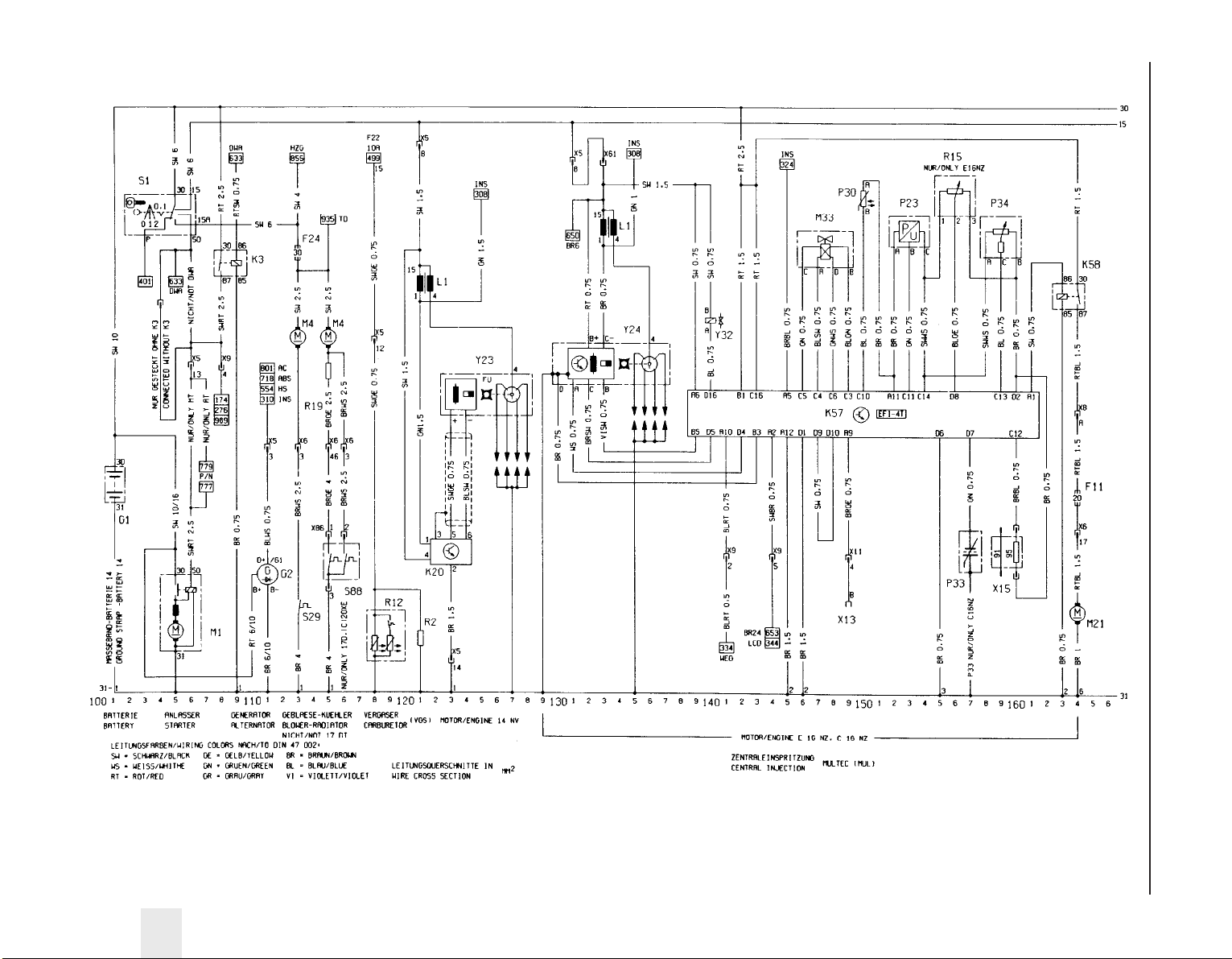
Wiring diagrams 12•41
12
Wiring diagram for 1991 models
Page 56
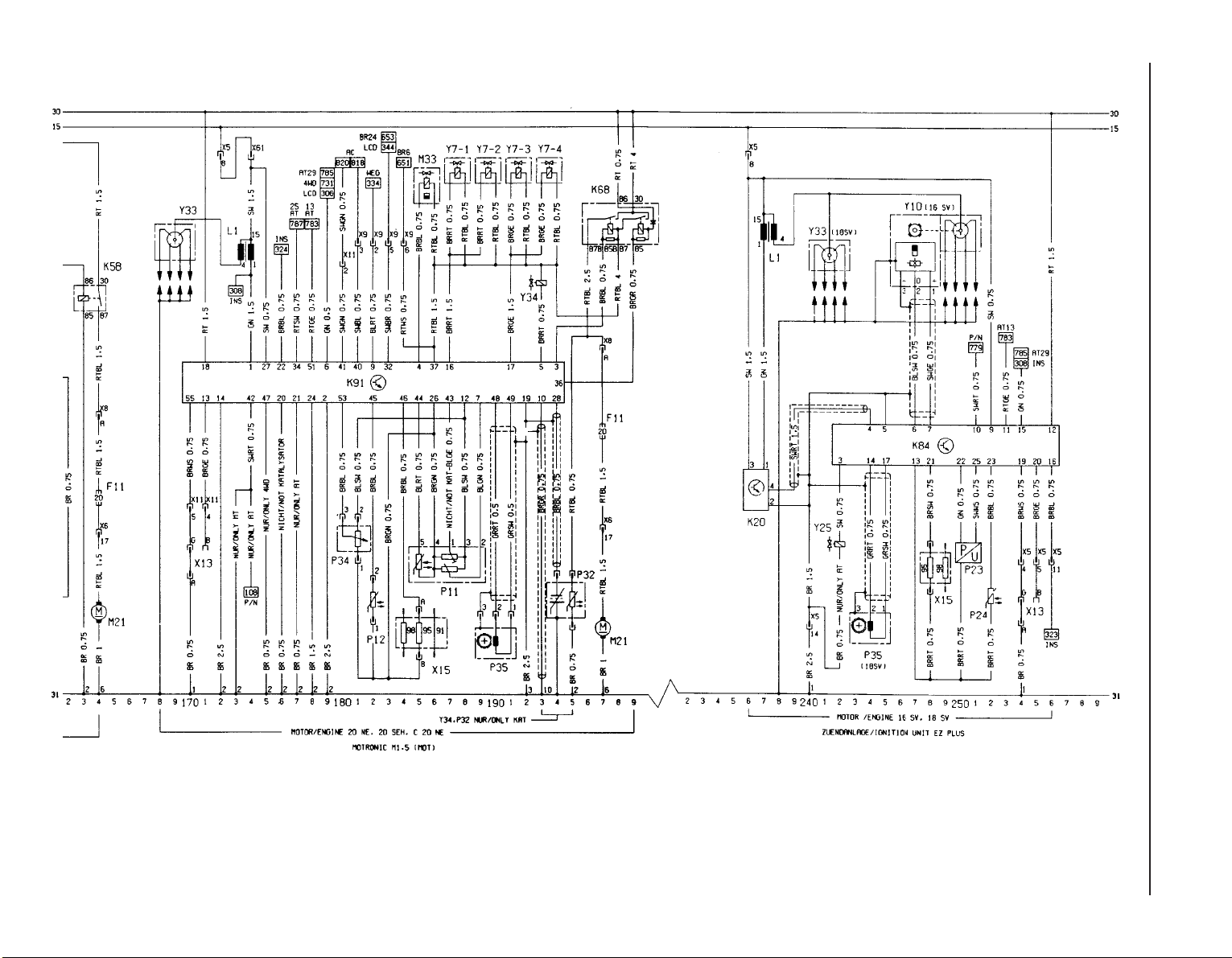
12•42 Wiring diagrams
Wiring diagram for 1991 models (continued)
Page 57
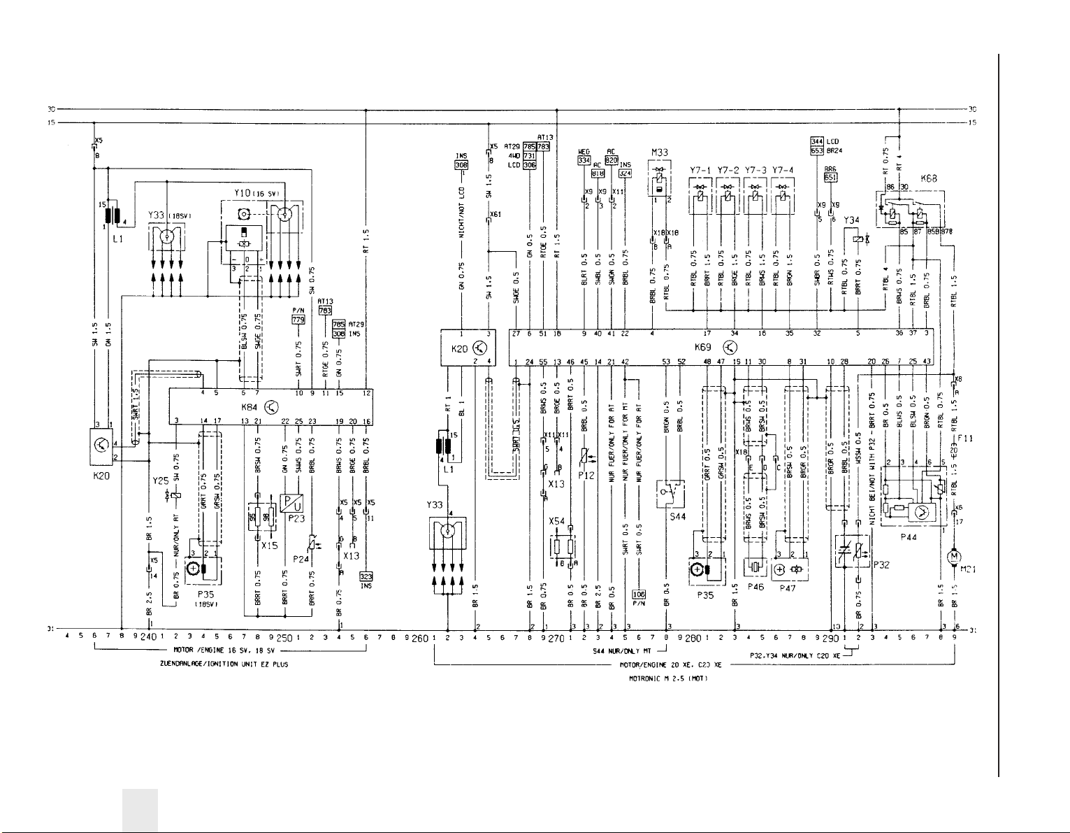
Wiring diagrams 12•43
12
Wiring diagram for 1991 models (continued)
Page 58
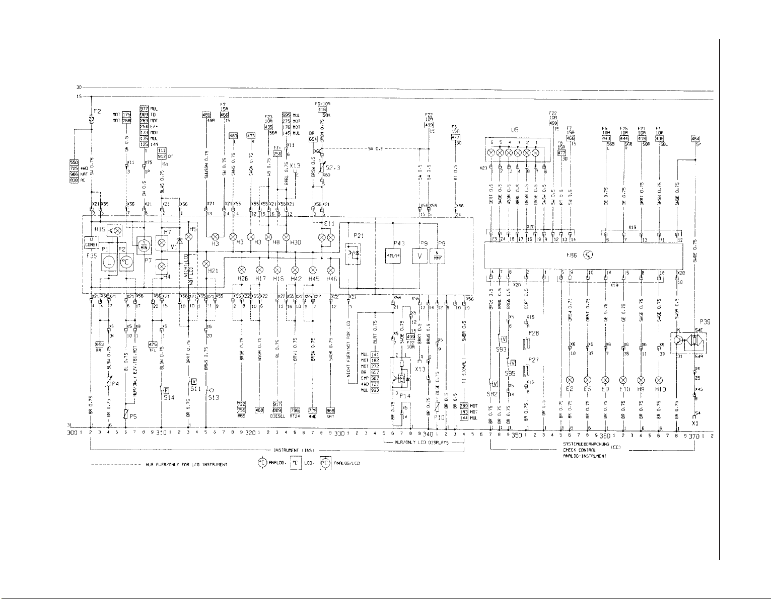
12•44 Wiring diagrams
Wiring diagram for 1991 models (continued)
Page 59
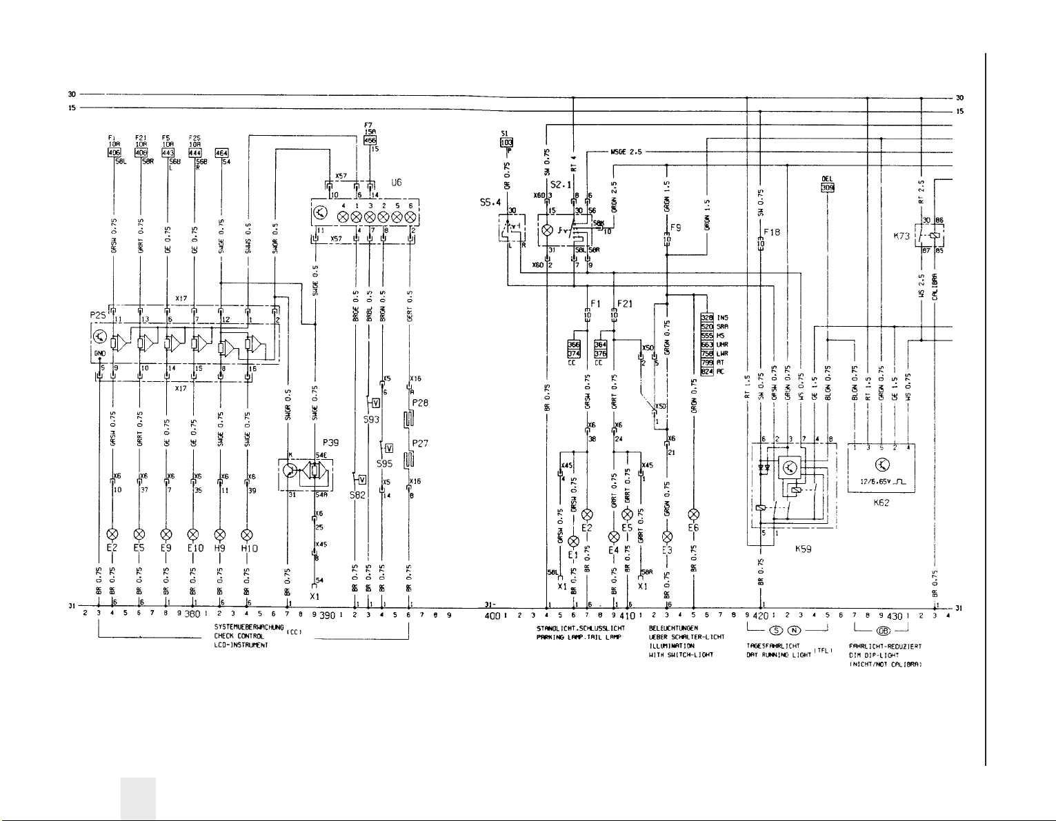
Wiring diagrams 12•45
12
Wiring diagram for 1991 models (continued)
Page 60
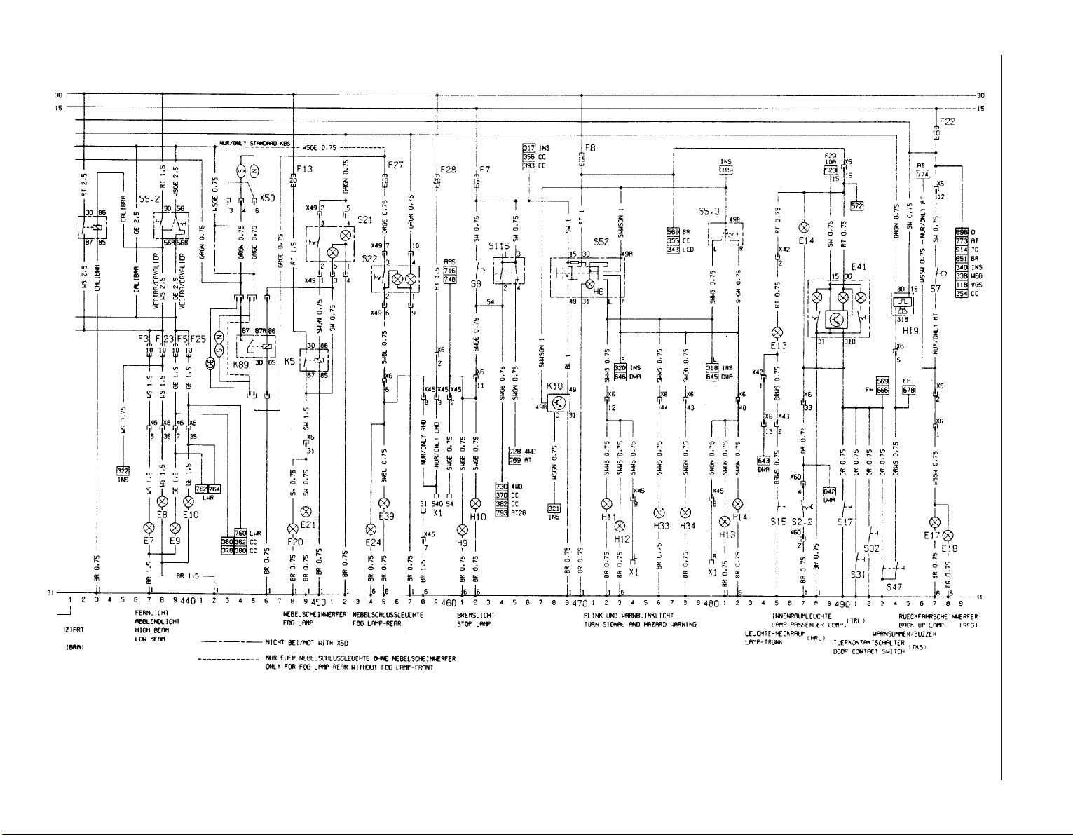
12•46 Wiring diagrams
Wiring diagram for 1991 models (continued)
Page 61
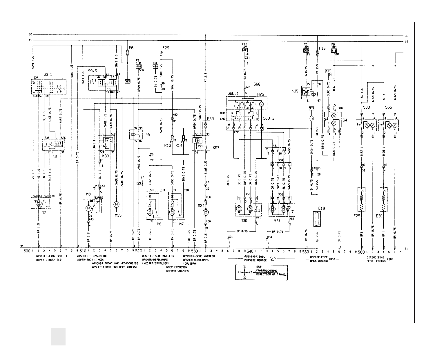
Wiring diagrams 12•47
12
Wiring diagram for 1991 models (continued)
Page 62
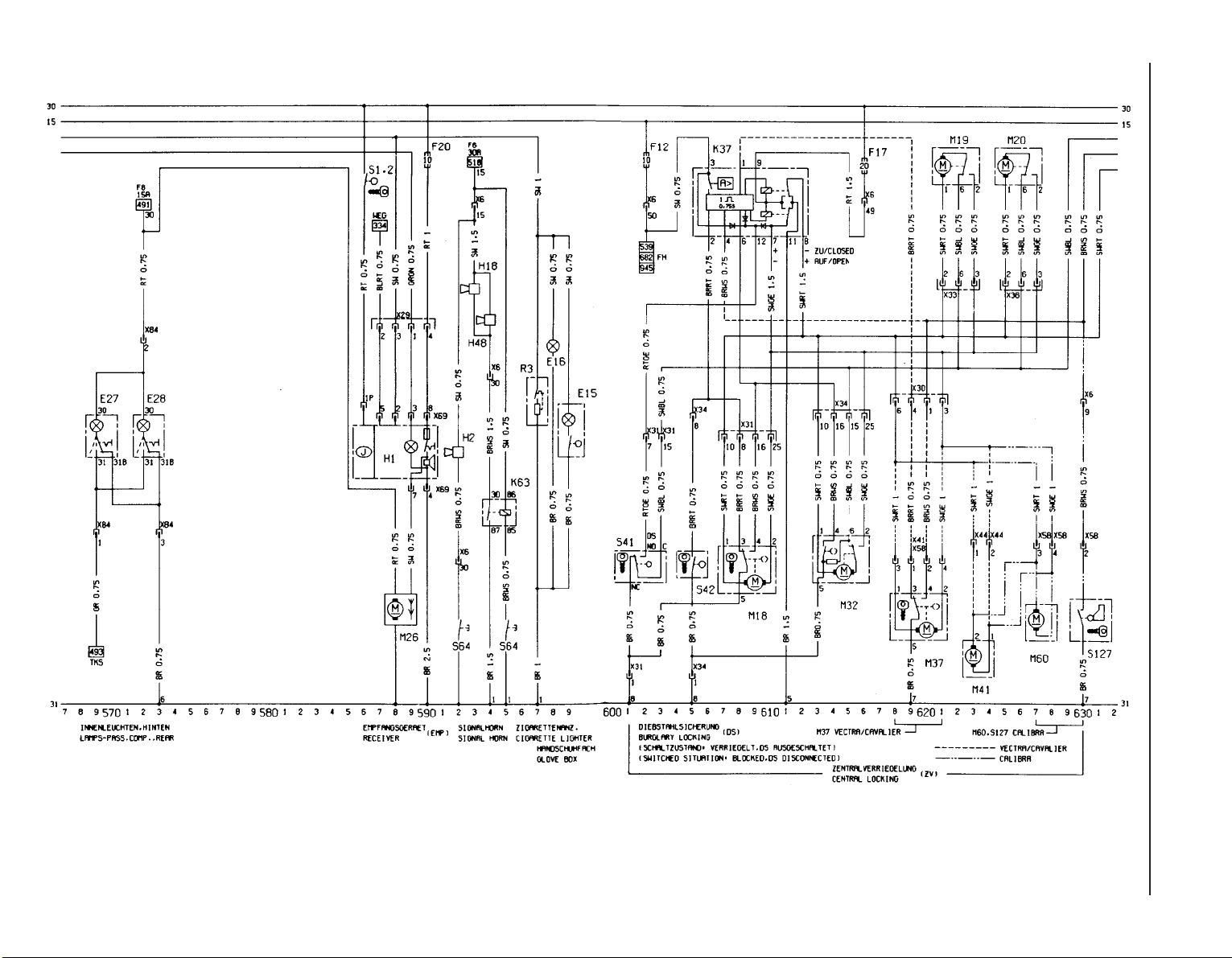
12•48 Wiring diagrams
Wiring diagram for 1991 models (continued)
Page 63
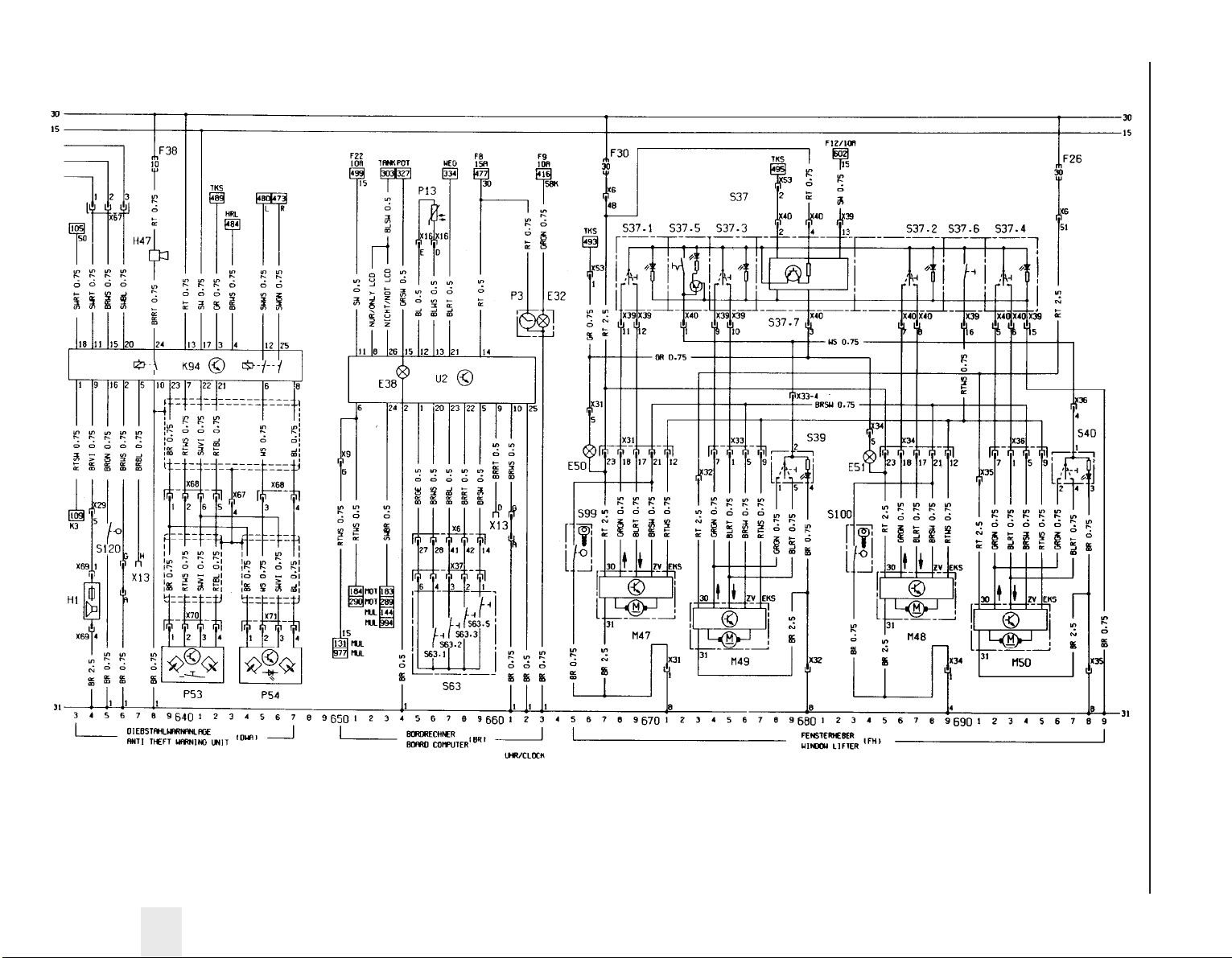
Wiring diagrams 12•49
12
Wiring diagram for 1991 models (continued)
Page 64
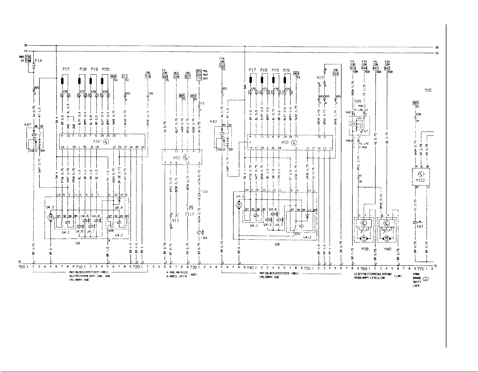
12•50 Wiring diagrams
Wiring diagram for 1991 models (continued)Wiring diagram for 1991 models (continued)
Page 65
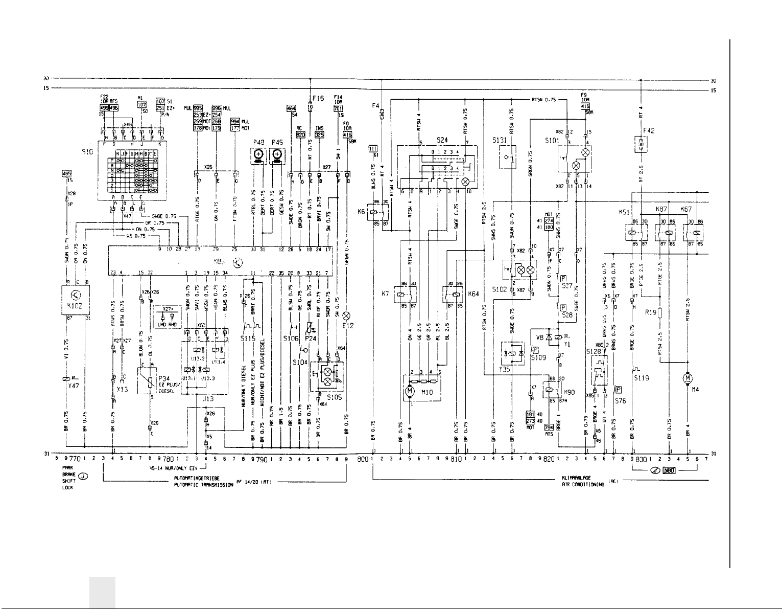
Wiring diagrams 12•51
12
Wiring diagram for 1991 models (continued)
Page 66
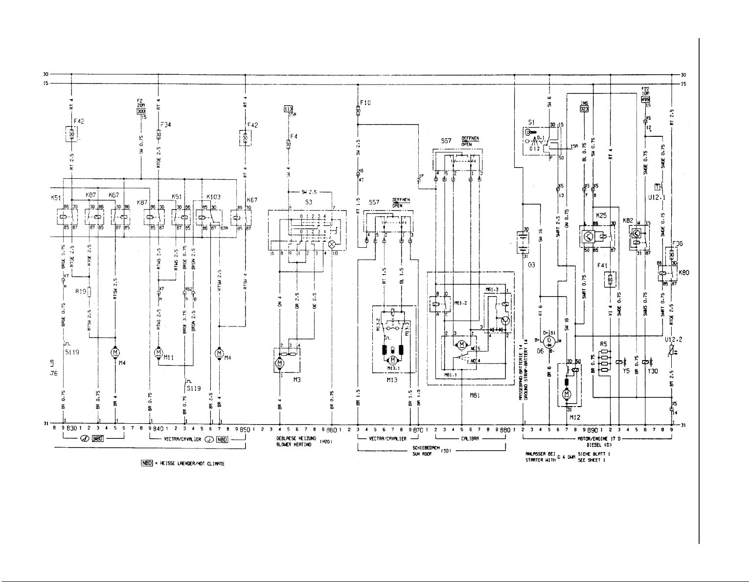
12•52 Wiring diagrams
Wiring diagram for 1991 models (continued)
Page 67
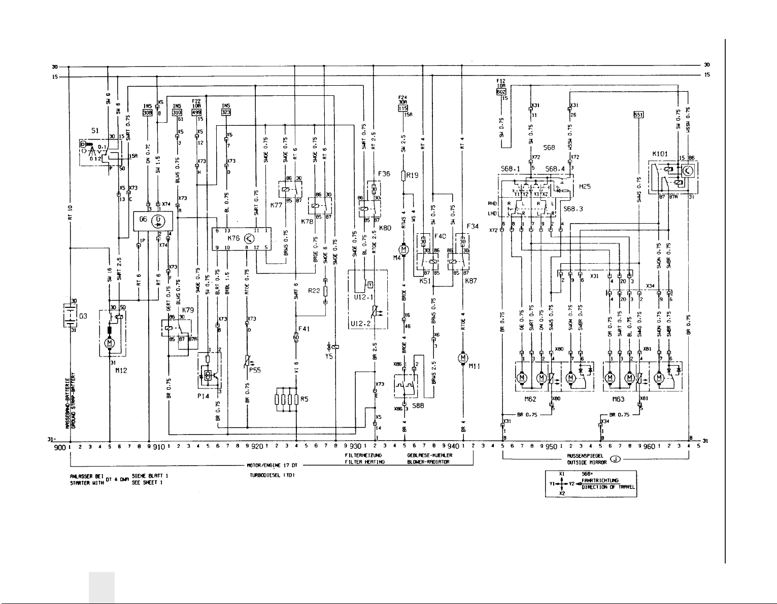
Wiring diagrams 12•53
12
Wiring diagram for 1991 models (continued)
Page 68
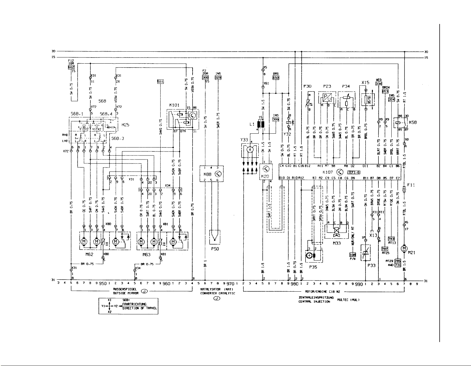
12•54 Wiring diagrams
Wiring diagram for 1991 models (continued)
Page 69

Wiring diagrams 12•55
12
Key to wiring diagrams for 1992 and later models
No Description Track No Description Track
E1 Left parking lamp 506
E2 Left tail lamp 507, 745
E3 Licence plate lamp 513
E4 Right parking lamp 509
E5 Right tail lamp 510, 746
E6 Engine compartment lamp 515
E7 Left high beam 535
E8 Right high beam 536
E9 Left low beam 537, 747
E10 Right low beam 538, 748
E11 Instrument lights 728, 729
E12 Selector lever lamp 498, 499
E13 Boot lamp 585
E14 Passenger compartment lamp 587
E15 Glove box lamp 677
E16 Cigarette lighter lamp 676
E17 Left reversing lamp 597
E18 Right reversing lamp 598
E19 Heated back window 652
E20 Left fog lamp 553
E21 Right fog lamp 554
E24 Left rear fog lamp 548
E25 Left front heating mat 660
E27 Left rear reading lamp 680, 681
E28 Right rear reading lamp 683, 684
E30 Right front heating mat 664
E32 Clock lamp 863
E37 Left mirror make-up lamp 686
E38 Computer lamp 854
E39 Right rear foglamp 549
E40 Right mirror make-up lamp 688
E41 Passenger compartment delay lamp 588 to 590
E50 Driver door lamp 866
E51 Passenger door lamp 884
F1 on Fuses Various
F35 Voltage stabilizer 702
G1 Battery 101
G2 Alternator 114
G6 Diesel alternator 402 to 405
H1 Radio 784 to 798
H3 Turn signal lamp telltale 716, 718
H4 Oil pressure telltale 710
H5 Brake fluid telltale 712
H6 Telltale hazard warning system 570
H7 Charging indicator lamp 710
H8 High beam telltale 722
H9 Left stop lamp 561, 749
H10 Right stop lamp 562, 750
H11 Left front turn signal lamp 572
H12 Left rear turn signal lamp 573
H13 Right front turn signal lamp 581
H14 Right rear turn signal lamp 582
H15 Fuel telltale 705, 706
H16 Preheating time telltale 715
H17 Trailer turn signal lamp telltale 717
H18 Horn 670
H19 Headlamps on warning buzzer 594, 595
H21 Parking brake telltale 713
H23 Airbag telltale 719
H25 Heated back window & mirror telltale 642, 765
H26 ABS telltale 721
H27 Safety checking warning buzzer 996 to 998
H28 Seat belt warning telltale 723
H30 Engine telltale 724
H33 Left auxiliary turn signal lamp 576
H34 Right auxiliary turn signal lamp 578
H36 Additional stop lamp 563
H37 Left front loudspeaker 788 to 790
H38 Right front loudspeaker 794 to 796
H39 Left rear loudspeaker 788, 789
H40 Right rear loudspeaker 791, 792
H42 Automatic program power telltale 725
H45 Four wheel drive telltale 727
H46 Catalytic converter temperature telltale 729
H47 Anti-theft warning unit horn 838
H48 Horn 671
H51 Traction control telltale 720
H52 Left front tweeter 787 to 791
H53 Right front tweeter 793 to 797
K3 Starter relay anti-theft warning unit 109, 110
K5 Fog lamps relay 554 to 555
K6 Air conditioning relay 901, 902
K7 Four stage air conditioning blower relay 904, 905
K8 Windshield wiper interval relay 603 to 606
K9 Headlamps washer unit relay 619, 620
K10 Flasher unit 567 to 569
K20 Ignition coil module 149, 150, 171, 172, 241, 242, 302 to 305,
361 to 364, 1001 to 1005, 1055 to 1061
K22 Coolant pump relay 133, 134, 969, 970
K25 Glow time relay 440 to 443
K26 Radiator blower relays 972 to 974
K27 Radiator blower relay 137 to 139
K30 Back window wiper interval relay 613 to 615
K31 Airbag control unit 1191 to 1198
K34 Radiator blower time delay relay 356 to 358, 956 to 958
K35 Heated back window & mirror time delay relay 650 to 652
K37 Central locking control unit 805 to 812
K51 Radiator blower relay 430, 431, 942, 943, 956, 957
K52 Radiator blower relay 145 to 147, 433,435,
982 to 984, 960 to 962
K57 Multec unit control 211 to 230, 244 to 262
K58 Fuel pump relay 231, 232, 262, 263
K59 Running light relay 520 to 525
K60 Compressor relay 931,932
K61 Motronic control unit 270 to 294, 307 to 337,
366 to 396, 1007 to 1037, 1063 to 1096
K63 Horn relay 671, 672
K64 1 stage air conditioning blower relay 913, 914
K67 Radiator blower relay 142, 143, 436, 437, 948,
949, 964, 965, 986, 987
K68 Fuel injection unit relay 295 to 299, 393 to 397,
334 to 338, 1093 to 1097, 1034 to 1038
K73 High beam relay (Calibra) 530, 531
K76 Glow time control unit 413 to 417
K77 Glow plugs relay 419, 420
K78 Preresistor relay (70A) 422, 423
K79 Charge indicator relay 406 to 408
K80 Filter heating relay 426, 427, 452, 453
K82 Engine revolution relay 447, 448
K83 Four wheel drive unit control 342 to 349
K84 EZ Plus control unit 155 to 166, 177 to 191
K85 Automatic transmission control unit 473 to 496
K86 Check control unit 736 to 752
K87 Radiator blower relay 945, 946, 953, 954, 977, 978
K88 Catalytic converter temperature control unit 462 to 464
K89 Rear fog lamp relay 543 to 545
K90 Compressor relay (automatic transmission only) 930, 931
K94 Anti-theft warning unit control unit 833 to 847
Page 70

12•56 Wiring diagrams
Key to wiring diagrams for 1992 and later models (continued)
No Description Track No Description Track
K95 Traction control control unit 1125 to 1140
K97 Headlamps washer pump time delay relay 630 to 632
K101 Parking position mirror relay 774 to 777
K102 Park brake shift lock control unit 469 to 471
L1 Ignition coil 150, 172, 205, 273, 241, 302, 361
L2 Ignition coil 1000 to 1004, 1054 to 1059
M1 Starter 105, 106
M2 Windshield wiper motor 601 to 604
M3 Heating blower motor 127 to 129
M4 Radiator blower motor 118, 120, 140, 356, 431, 948, 954, 980
M6 Left headlamp wiper motor 622 to 624
M7 Right headlamp wiper motor 626 to 628
M8 Back window wiper motor 611 to 613
M10 Air conditioning blower motor 905 to 908
M11 Radiator blower motor 136, 434, 962, 984
M13 Vectra/Cavalier sun roof motor 1172 to 1175
M13.1Sun roof motor 1172, 1174
M13.2Timing box microswitch 1172
M13.3Timing box microswitch 1174
M18 Driver door central locking motor 807 to 810
M19 Left rear door central locking motor 821 to 823
M20 Right rear door central locking motor 825 to 827
M21 Fuel pump 232, 263, 297, 339, 399, 834, 1098, 1039
M23 Alternator blower motor 135, 974
M24 Headlamps washer pump 632
M26 Automatic antenna motor 798 to 799
M30 Driver side outside mirror 638 to 641
M31 Passenger side outside mirror 644 to 647
M32 Passenger door central locking motor 813 to 816
M33 Idle speed actuator 285, 286, 317, 318, 381,
382, 1019, 1020, 1075, 1076
M37 Tail gate/boot lid central locking motor 818 to 821
M39 Left headlamp levelling motor 692 to 695
M40 Right headlamp levelling motor 696 to 699
M41 Fuel filler door central locking motor 823, 824
M47 Driver door window lifter motor 867 to 871
M48 Passenger door window lifter motor 885 to 889
M49 Left rear window lifter motor 873 to 877
M50 Right rear window lifter motor 891 to 895
M55 Windshield and back window washer pump 617
M57 Coolant pump 134, 970
M60 Calibra tailgate central locking motor 827, 828
M61 Calibra sun roof motor 1178 to 1186
M61.1Sun roof motor 1179 to 1182
M61.2Relay 1 1178, 1179
M61.3Relay 2 1184 to 1186
M62 Driver side outside mirror 760 to 767
M63 Passenger side outside mirror 769 to 776
M65 TC throttle valve actuator 1130 to 1134
M66 Idle air stepper motor 215 to 218, 250 to 253
P1 Fuel indicator 704
P2 Coolant temperature indicator 706
P3 Clock 862
P4 Fuel sensor 704
P5 Coolant temperature sensor 706
P7 Tachometer 708
P11 Airflow meter 285 to 289
P12 Coolant temperature sensor 282, 381
P13 Outside temperature sensor 856
P14 Distance sensor 412, 413
P17 Left front revolution sensor 1110, 1154
P18 Right front revolution sensor 1113, 1157
P19 Left rear revolution sensor 1116, 1160
P20 Right rear revolution sensor 1119, 1163
P21 Distance sensor 731
P23 Intake manifold absolute pressure sensor 160, 161, 185, 186,
217 to 219, 250 to 252
P24 Engine oil temperature sensor 162, 187
P27 Left front brake lining sensor 740
P28 Right front brake lining sensor 740
P29 Intake manifold temperature sensor 382, 1016, 1072
P30 Coolant temperature sensor 215, 248, 313, 1017, 1073
P32 Heated exhaust oxygen sensor 294, 295, 331, 332, 391,
392, 1034, 1035, 1093, 1094
P33 Exhaust oxygen sensor 229, 257
P34 Throttle valve potentiometer 221 to 223, 280, 281, 253 to 255,
383 to 385, 478, 479, 1018, 1019, 1074, 1075
P35 Crankshaft impulse sensor178 to 180, 289 to 291, 248 to 250,
318 to 320, 373 to 375, 1025 to 1027, 1084 to 1086
P38 Transmission oil temperature sensor 494
P39 Trailer bulb test sensor 752 to 754
P43 Electronic speedometer 733
P44 Air mass meter 393 to 397, 334 to 338,
1037, 1038, 1096, 1097
P45 Transmission input revolution sensor 490, 491
P46 Knock control sensor 322, 323, 377, 378,
1022, 1023, 1078, 1079
P47 Cylinder identification hall sensor 325 to 327, 385 to 387,
1028 to 1030, 1087, 1089
P48 Automatic transmission distance sensor 488, 489
P50 Catalytic converter temperature sensor 463, 464
P53 Driver side anti-theft warning unit sensor 839 to 847
P54 Passenger side anti-theft warning unit sensor 839 to 847
P55 Engine coolant temperature sensor 415
P56 Knock control sensor II 1080, 1081
P57 Antenna 797
R3 Cigarette lighter 675
R5 Glow plugs 418 to 420, 441 to 443
R13 Left heated washer nozzle 626
R14 Right heated washer nozzle 628
R19 Radiator blower preresistor 120, 140, 945
R22 Glow plugs pre-resistor 423
R23 Driver airbag squib 1194
S1 Starter switch 103 to 106
S1.2 Key contact switch 783
S2 Light switch assy
S2.1 Light switch 504 to 507
S2.2 Passenger compartment lamp switch 587
S2.3 Instrument lights dimmer 728
S3 Heating blower switch 123 to 130
S4 Heated back window & mirror switch 654 to 657
S5 Turn signal switch assy
S5.2 Low beam switch 536, 537
S5.3 Turn signal switch 580 to 582
S5.4 Parking lamp switch 501, 502
S7 Back up lamp switch 597, 599
S8 Stop lamp switch 562
S9 Wiper unit switch
S9.2 Interval windshield wiper switch 601 to 604
S9.5 Back window and washer unit wiper switch 614 to 616
S10 Automatic transmission switch 472 to 478
S11 Brake fluid control switch 712
S13 Parking brake switch 713
S14 Oil pressure switch 710
S15 Boot lamp switch 585
S17 Passenger door contact switch 590
S20 Pressure switch
S20.1 Low pressure compressor switch 925
Page 71

Wiring diagrams 12•57
12
Key to wiring diagrams for 1992 and later models (continued)
No Description Track No Description Track
S20.2 High pressure compressor switch 925
S20.3 High pressure blower compressor switch 939
S21 Fog lamps switch 555 to 557
S22 Rear fog lamp switch 549 to 551
S24 Air conditioning blower switch 904 to 911
S29 Coolant temperature switch 118, 137, 357, 942, 957, 972
S30 Left front heating mat switch 660 to 662
S31 Rear left door contact switch 591
S32 Rear right door contact switch 592
S33 Traction control switch 1130, 1131
S37 Window lifter switch 868 to 894
S37.1 Left window lifter switch 868 to 870
S37.2 Right window lifter switch 886 to 888
S37.3 Left rear window lifter switch 874 to 876
S37.4 Right rear window lifter switch 892 to 894
S37.5 Safety switch 872, 873
S37.6 Window anti-jam off switch 890
S37.7 Automatic window lifter control 877 to 882
S39 Left rear door window lifter switch 878 to 880
S40 Right rear door window lifter switch 896 to 898
S41 Driver door burglary locking switch 800 to 802
S42 Passenger door central locking switch 805
S44 Throttle valve switch 316, 317
S47 Driver door contact switch 593, 594
S52 Hazard warning switch 569 to 573
S53 First gear identification switch 372
S55 Right front heating mat switch 664 to 666
S57 Sun roof switch 1170 to 1183
S63 Computer switch
S63.1 Function reset switch 856
S63.2 Clock hours adjustment switch 857
S63.3 Function select switch 858
S63.4 Clock minute adjustment switch 859
S64 Horn switch 672
S68 Outside mirror switch assy
S68.1 Outside mirror adjustment switch 638 to 640, 758 to 762
S68.3 Left/right outside mirror switch 637 to 641, 759 to 763
S68.4 Parking position switch 765
S82 Washer fluid minimum capacity control switch 736
S88 2 stage coolant temperature switch120, 121, 137, 138, 430, 431
S89 Seat belt switch 998
S93 Coolant minimum capacity control switch 737
S95 Engine oil minuimum capacity control switch 738
S98 Headlamps levelling switch 691 to 693
S99 ZV driver door window lifter switch 865
S100 ZV passenger door window lifter switch 883
S101 Compressor switch 926 to 928
S102 Circulation switch 918 to 920
S103 Transmission temperature switch 350
S104 Kickdown switch 493
S105 Start-up assistance switch 495 to 497
S106 Economy power program switch 492
S109 Acceleration revolution pressure switch 921
S115 Coolant temperature switch 487, 488
S116 Stop lamp switch 564, 565
S117 Hydraulic pressure switch 346
S120 Engine compartment hood (anti-theft warning unit) switch 835
S127 Calibra tail gate central locking switch 831
S128 Coolant temperature switch 936,937
S131 Defroster lever limit switch 918
U2 Computer 851 to 862
U4 ABS hydroaggregate 1102 to 1122, 1146 to 1164
U4.1 Pump motor relay 1102, 1103, 1146, 1147
U4.2 Solenoid valves relay 1104, 1105, 1148, 1149
U4.3 Pump motor 1102,1146
U4.4 Diode 1105,1149
U4.5 Left front solenoid valve 1109,1153
U4.6 Right front solenoid valve 1111,1155
U4.7 Rear axle solenoid valve 1113,1157
U4.8 ABS control unit 1106 to 1122, 1150 to 1164
U4.9 Solenoid valves plug 1109 to 1113, 1153 to 1157
U5 Check control display
U5.1 Washer fluid minimum capacity telltale 741
U5.2 Oil minimum capacity telltale 740
U5.3 Coolant minimum capacity telltale 739
U5.4 Tail light & low beam telltale 738
U5.5 Stop light failure telltale 737
U5.6 Front brake lining telltale 736
U12 Filter heater
U12.1Temperature switch 426, 452
U12.2Filter heater 427, 453
U13 Automatic transmission
U13.1Solenoid valve (shift 1) 481
U13.2Solenoid valve (shift 2) 482
U13.3Solenoid valve (lock up control) 483
U13.4Solenoid valve (pressure control) 484
U17 Roof antenna amplifier 795
V1 Brake fluid test bulb diode 712
V8 Air conditioning compressor diode 926
X1 on Wiring connectors Various
X10 Anti theft warning unit code 837
X13 Diagnostic link 164, 165, 189, 190, 226, 270, 271, 258, 259,
309, 310, 370, 371, 343, 344, 473, 474, 573, 725, 836, 837, 860,
861, 1012, 1013, 1069, 1070, 1118, 1119, 1136, 1162, 1163
X15 Octane number plug 157, 158, 182, 183, 225, 226,
257, 258, 284, 285
X54 Ignition coding plug 310, 311, 1014, 1070, 1071
Y1 Air conditioning compressor clutch 925
Y4 Headlamps washer solenoid valve 620
Y5 Fuel solenoid valve 410, 445
Y7 Fuel injection valves 287 to 294,320 to 327,
384 to 391,1025 to 1032,1078 to 1089
Y10 Hall sensor ignition distributor 153 to 158
Y11 Hot start solenoid valve 375, 376
Y12 Charging pressure control changeover valve 377, 378
Y18 Exhaust gas recirculation valve 1093
Y23 Inductive sensor distributor 201 to 208
Y24 Distributor (inductive discharge)
Y25 Acceleration revolution solenoid valve 155, 177
Y30 Cold start acceleration solenoid valve 448
Y32 Fuel injection valve 212, 245
Y33 Ignition distributor 175 to 177, 268 to 270, 238 to 240,
301 to 303, 360 to 362
Y34 Tank ventilation valve 293, 331, 332, 379, 380,
1092, 1016, 1017,
Y35 Circulation solenoid valve 918
Y44 Four wheel drive solenoid valve 350
Y47 Park brake shift lock lifting magnet 469
Page 72
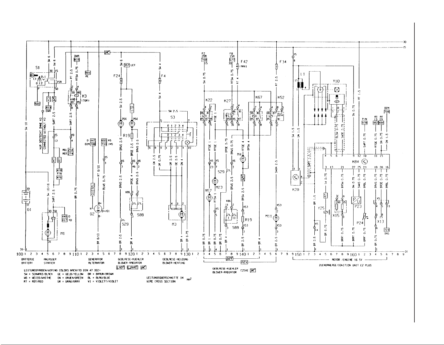
12•58 Wiring diagrams
Wiring diagram for 1992-on models
Page 73
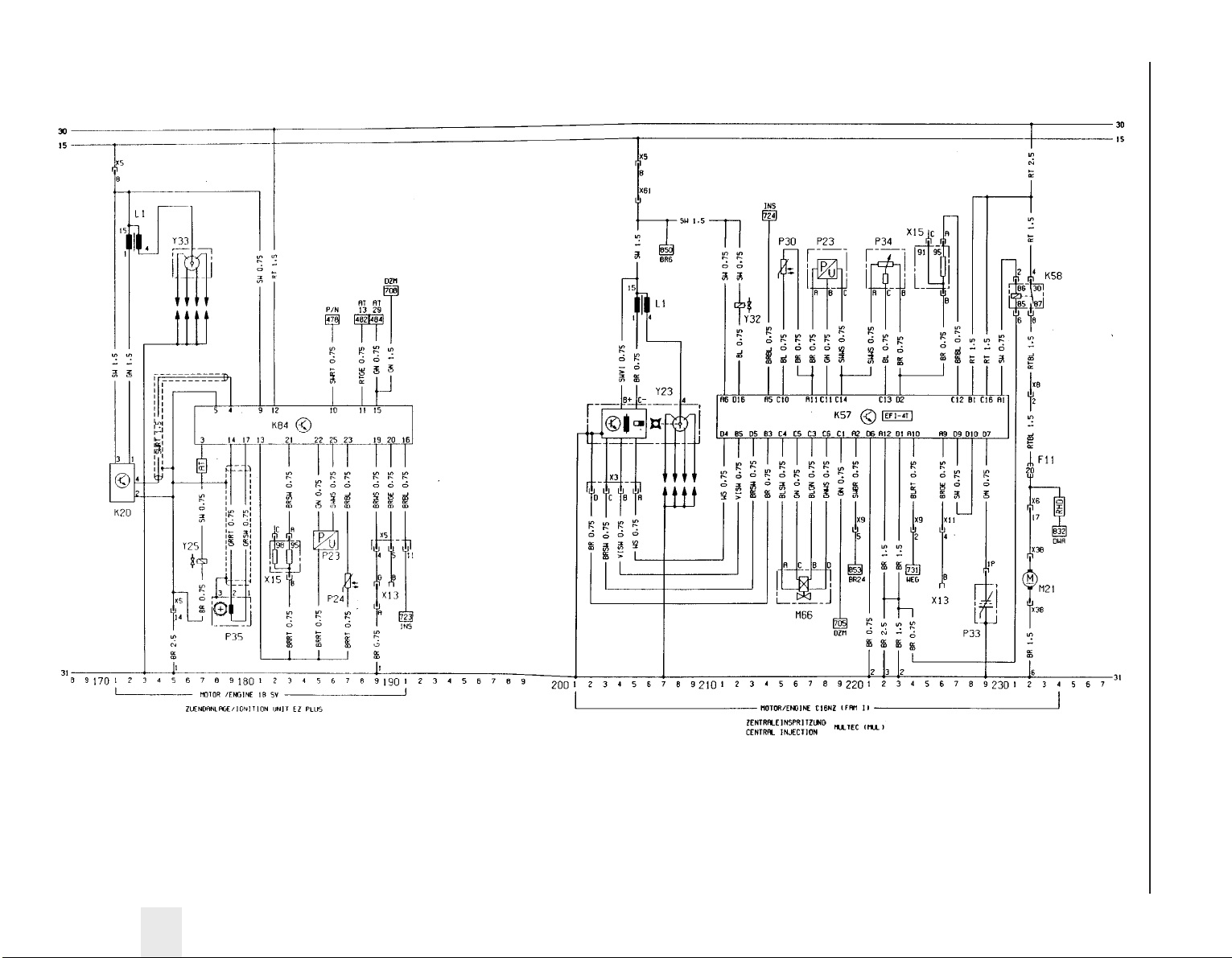
Wiring diagrams 12•59
12
Wiring diagram for 1992-on models (continued)
Page 74
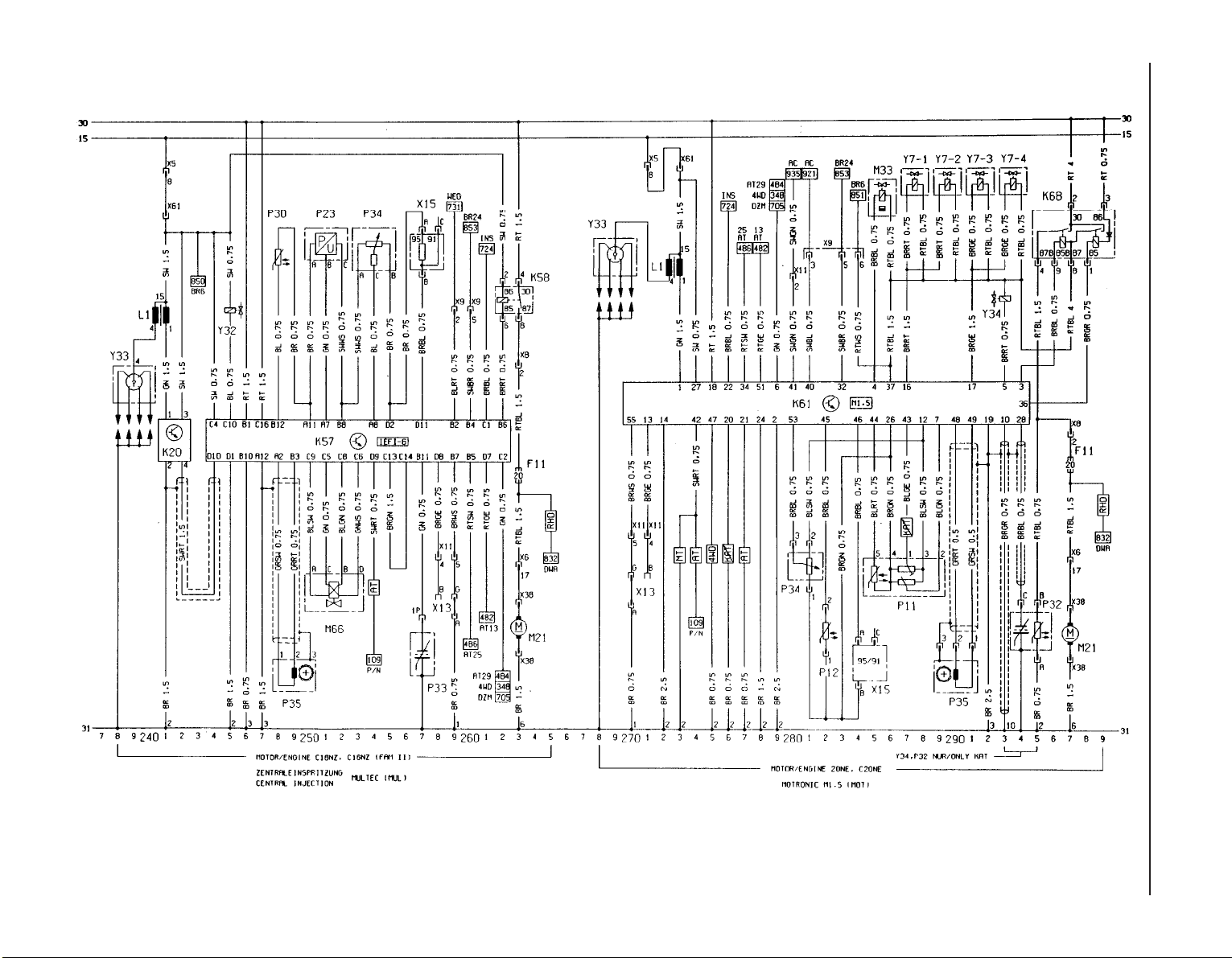
12•60 Wiring diagrams
Wiring diagram for 1992-on models (continued)
Page 75
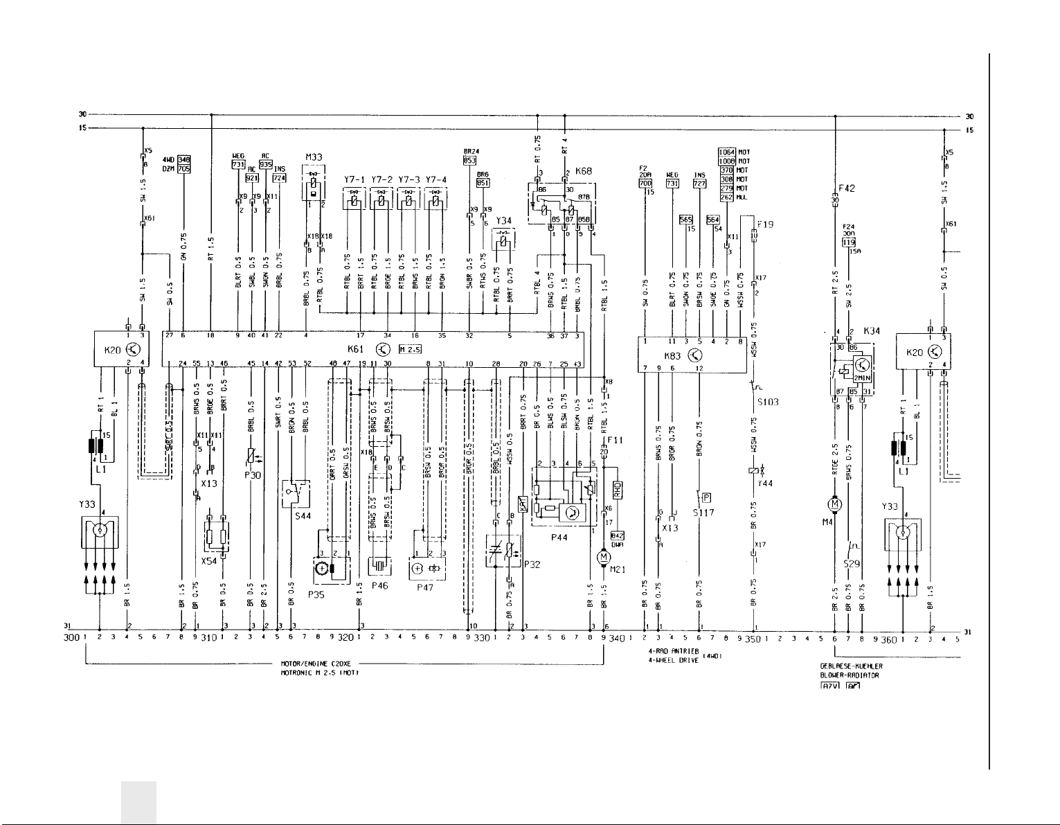
Wiring diagrams 12•61
12
Wiring diagram for 1992-on models (continued)
Page 76
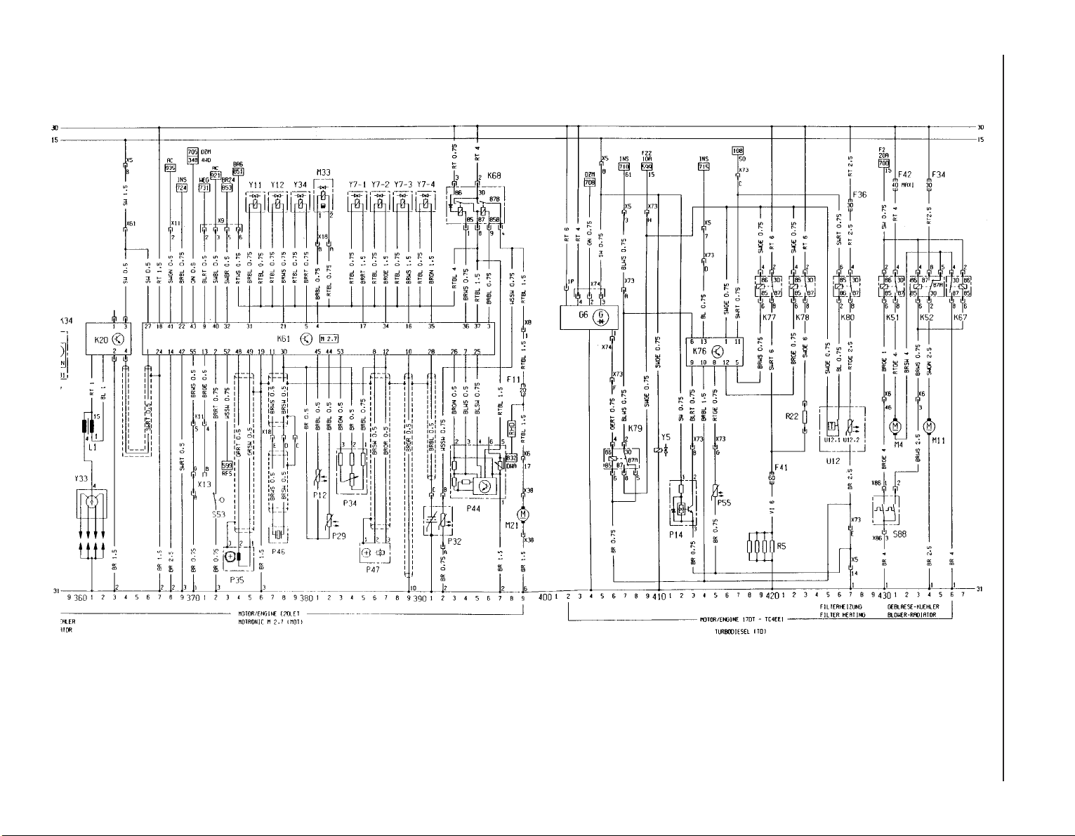
12•62 Wiring diagrams
Wiring diagram for 1992-on models (continued)
Page 77
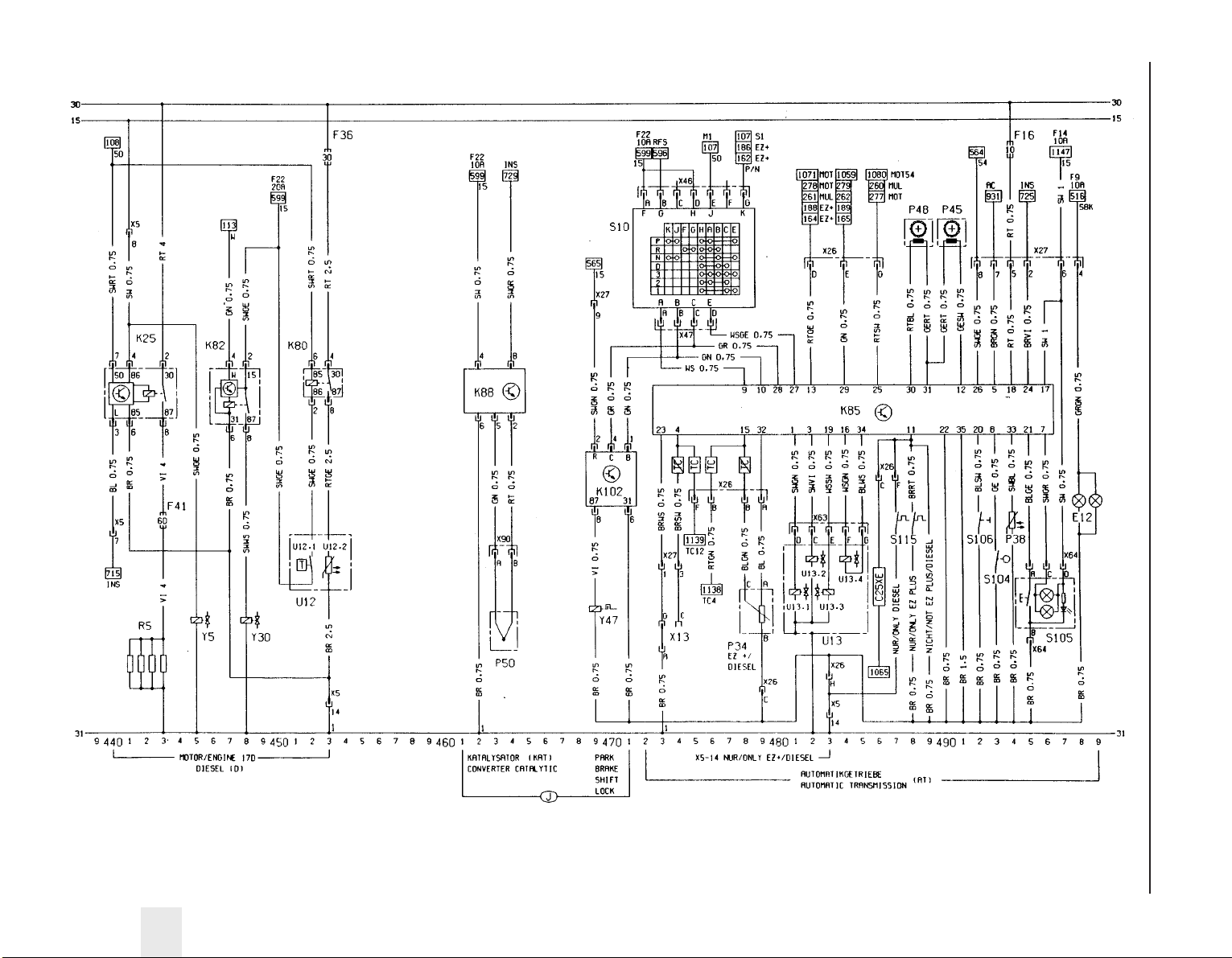
Wiring diagrams 12•63
12
Wiring diagram for 1992-on models (continued)
Page 78
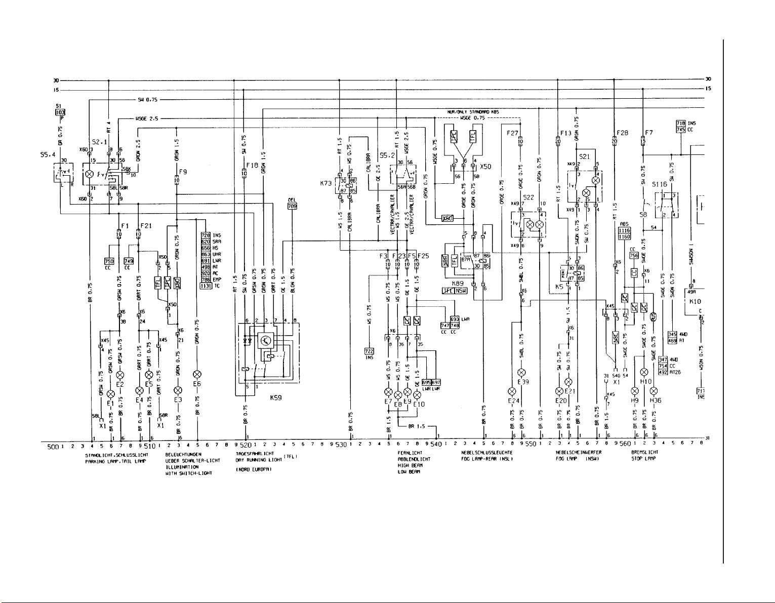
12•64 Wiring diagrams
Wiring diagram for 1992-on models (continued)
Page 79
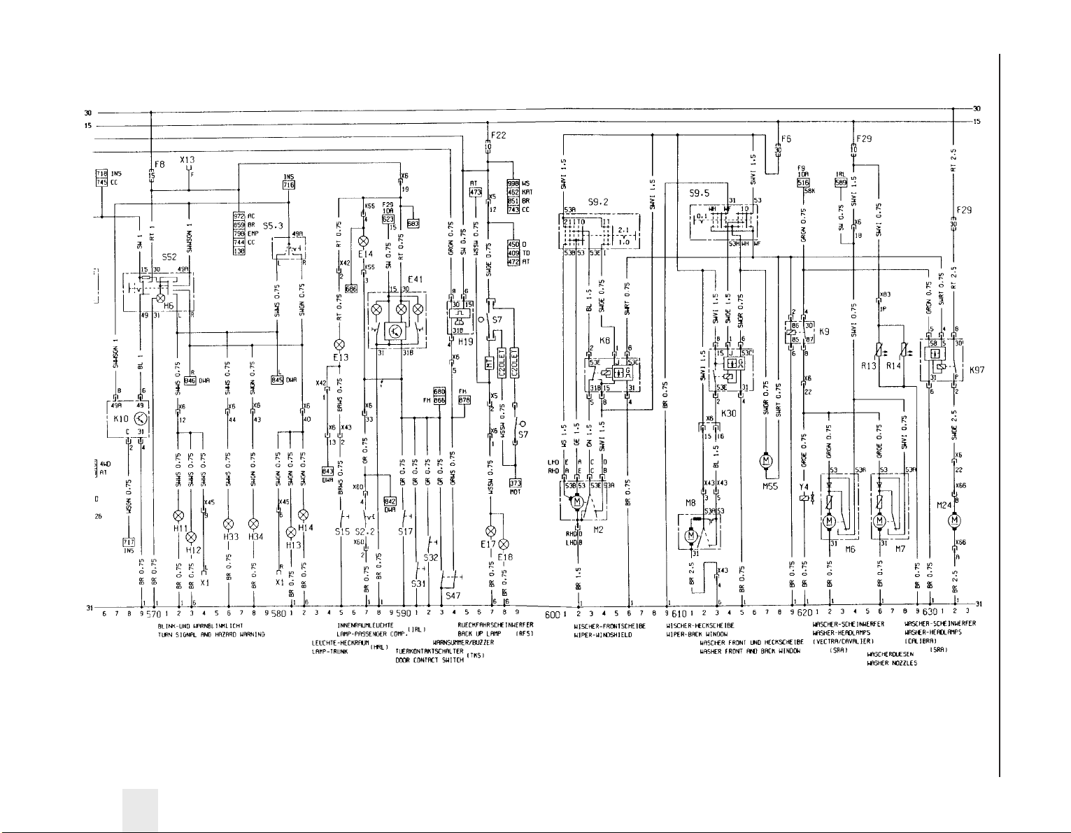
Wiring diagrams 12•65
12
Wiring diagram for 1992-on models (continued)
Page 80
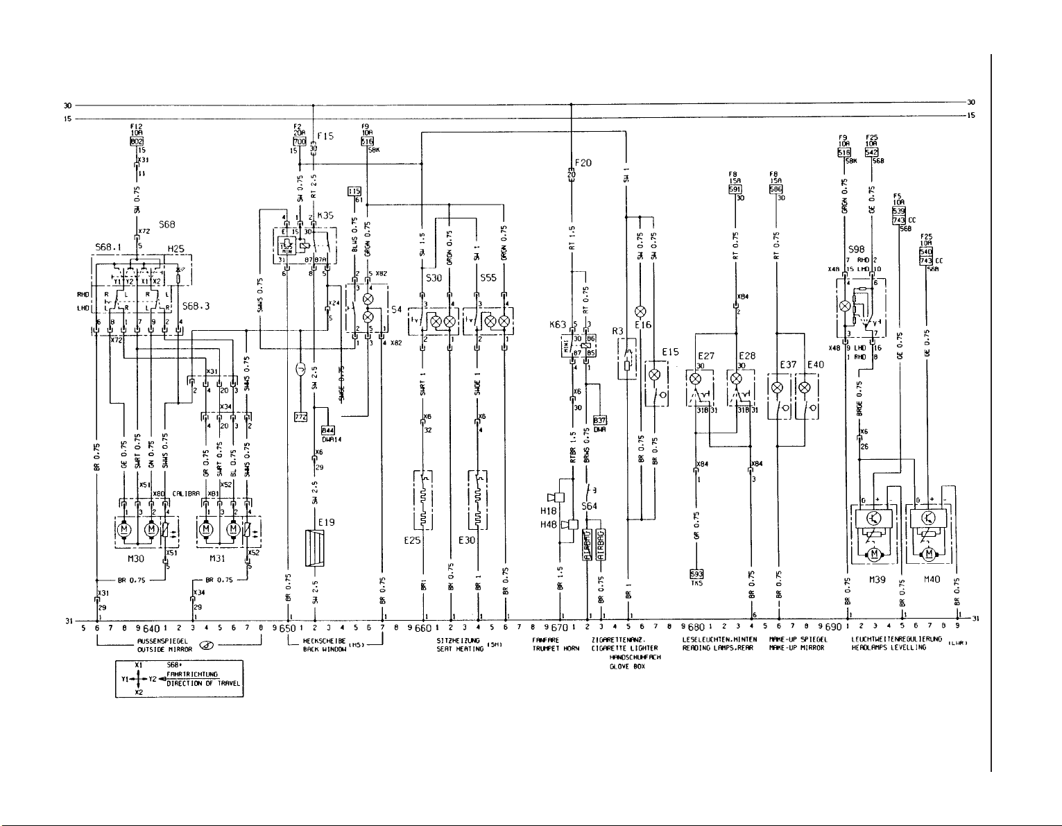
12•66 Wiring diagrams
Wiring diagram for 1992-on models (continued)
Page 81
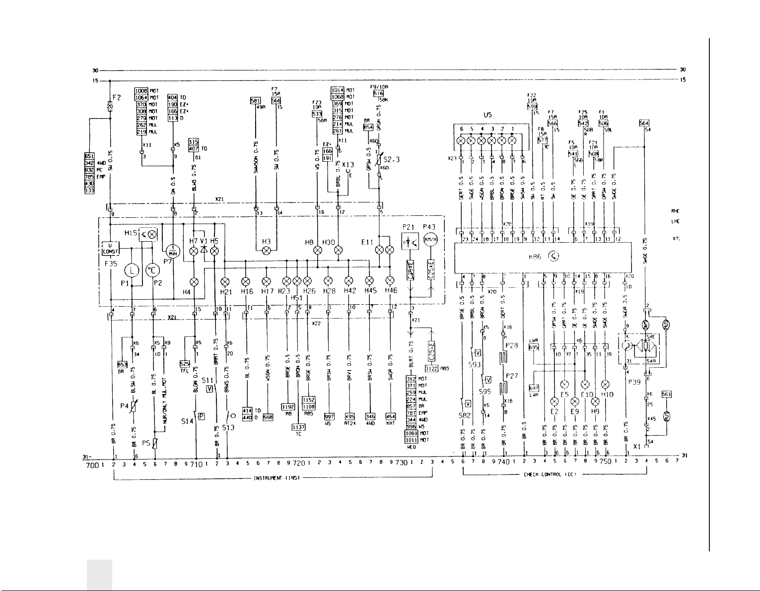
Wiring diagrams 12•67
12
Wiring diagram for 1992-on models (continued)
Page 82
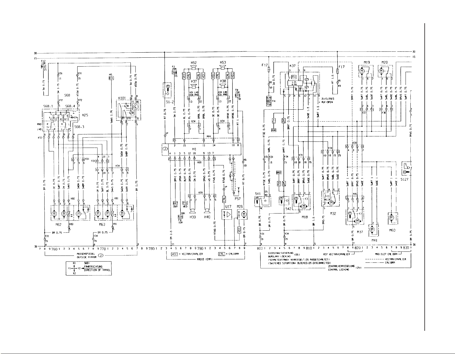
12•68 Wiring diagrams
Wiring diagram for 1992-on models (continued)
Page 83
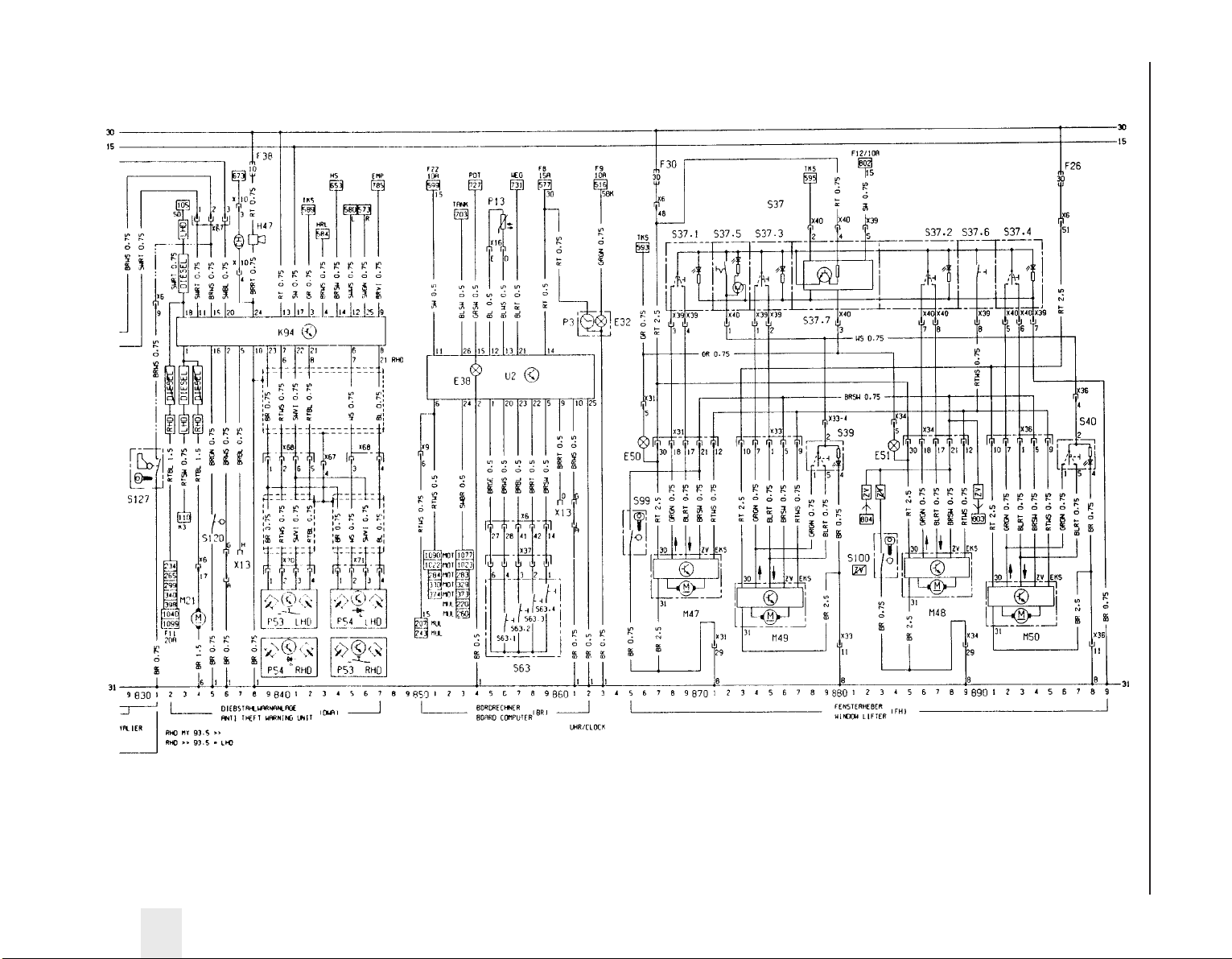
Wiring diagrams 12•69
12
Wiring diagram for 1992-on models (continued)
Page 84
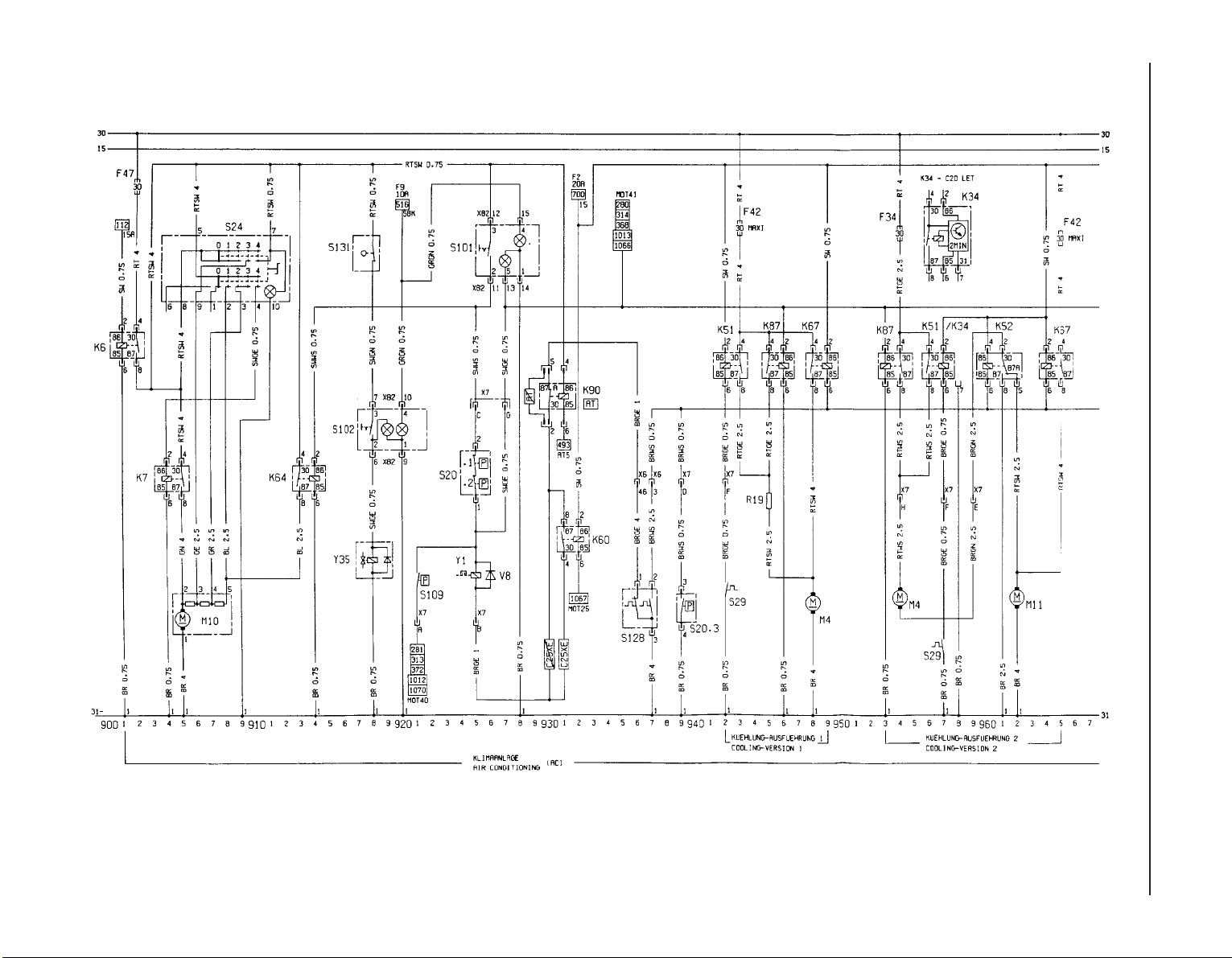
12•70 Wiring diagrams
Wiring diagram for 1992-on models (continued)
Page 85
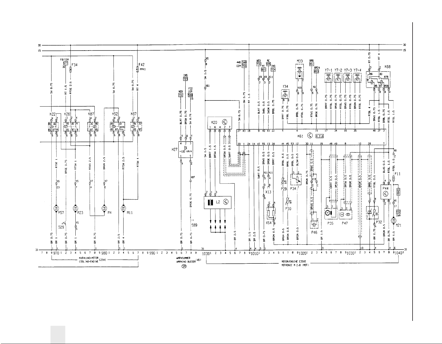
Wiring diagrams 12•71
12
Wiring diagram for 1992-on models (continued)
Page 86
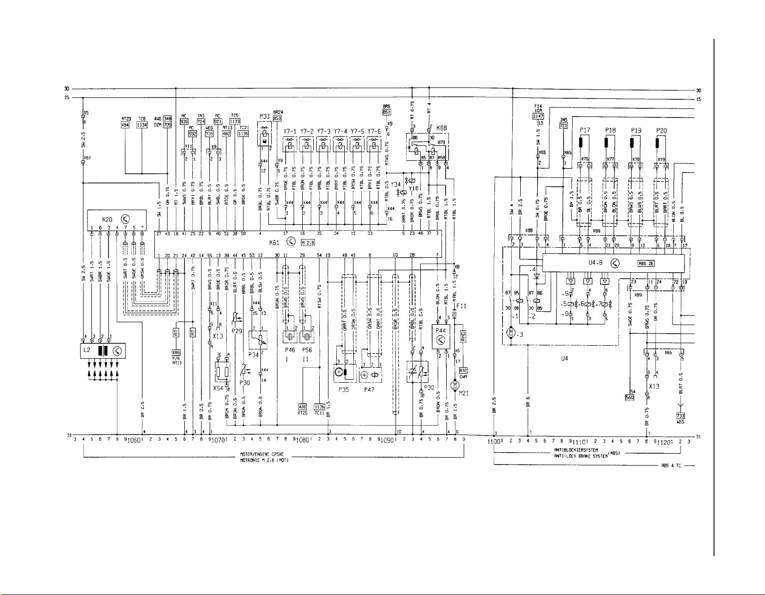
12•72 Wiring diagrams
Wiring diagram for 1992-on models (continued)
Page 87
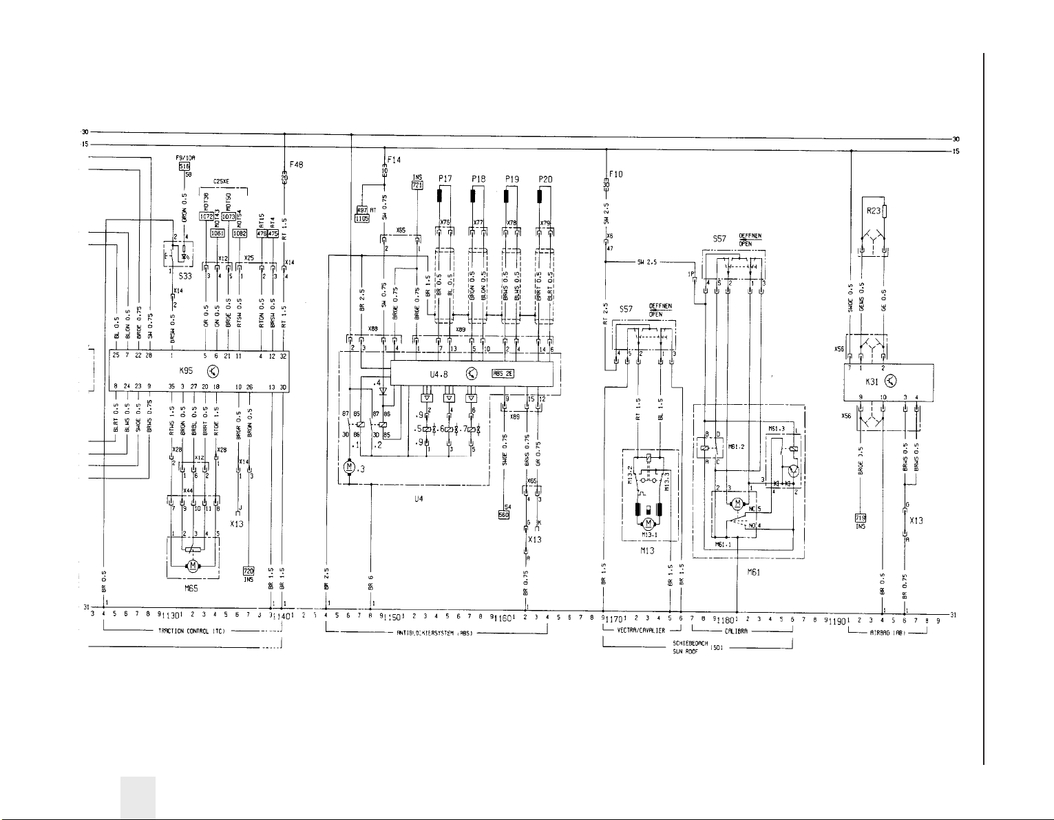
Wiring diagrams 12•73
12
Wiring diagram for 1992-on models (continued)
Page 88

5
System type . . . . . . . . . . . . . . . . . . . . . . . . . . . . . . . . . . . . . . . . . . . 12 volt, negative earth
Battery capacity . . . . . . . . . . . . . . . . . . . . . . . . . . . . . . . . . . . . . . . 36, 44, 55 or 66 Ah
Alternator
Type . . . . . . . . . . . . . . . . . . . . . . . . . . . . . . . . . . . . . . . . . . . . . . . . . . . . Bosch or Delco-Remy
Output . . . . . . . . . . . . . . . . . . . . . . . . . . . . . . . . . . . . . . . . . . . . . . . . . . . 55 or 70 A, depending upon model
Minimum brush length:
Bosch type alternator . . . . . . . . . . . . . . . . . . . . . . . . . . . . . . . . . . . . . 5.0 mm protrusion
Delco-Remy type alternator . . . . . . . . . . . . . . . . . . . . . . . . . . . . . . . . 11.0 mm overall length
Starter motor
Type . . . . . . . . . . . . . . . . . . . . . . . . . . . . . . . . . . . . . . . . . . . . . . . . . . . . Pre-engaged, Bosch or Delco-Remy
Minimum brush length:
Bosch DF type starter motor . . . . . . . . . . . . . . . . . . . . . . . . . . . . . . . 11.5 mm
Bosch DM type starter motor . . . . . . . . . . . . . . . . . . . . . . . . . . . . . . . 3.0 mm
Bosch DW type starter motor . . . . . . . . . . . . . . . . . . . . . . . . . . . . . . . 4.5 mm
Delco-Remy type starter motor . . . . . . . . . . . . . . . . . . . . . . . . . . . . . 4.0 mm
System type
14 NV . . . . . . . . . . . . . . . . . . . . . . . . . . . . . . . . . . . . . . . . . . . . . . . . . HEI (High Energy Ignition) system
16 SV and 18 SV . . . . . . . . . . . . . . . . . . . . . . . . . . . . . . . . . . . . . . . . . MSTS-i (Microprocessor Spark Timing System)
C16 NZ, C16 NZ2 and C18 NZ . . . . . . . . . . . . . . . . . . . . . . . . . . . . . . Multec, with MSTS-i
X16 SZ . . . . . . . . . . . . . . . . . . . . . . . . . . . . . . . . . . . . . . . . . . . . . . . . Multec, with DIS (Direct Ignition System)
20 NE, C20 NE and 20 SEH, (up to 1990) . . . . . . . . . . . . . . . . . . . . . Motronic M4.1
20 NE, C20 NE and 20 SEH, (from 1990) . . . . . . . . . . . . . . . . . . . . . . Motronic M1.5
20 XEJ and C20 XE, (up to 1993) . . . . . . . . . . . . . . . . . . . . . . . . . . . . Motronic M2.5
C20 XE (from 1993) . . . . . . . . . . . . . . . . . . . . . . . . . . . . . . . . . . . . . . . Motronic M2.8
X20 XEV . . . . . . . . . . . . . . . . . . . . . . . . . . . . . . . . . . . . . . . . . . . . . . . Simtec 56.1
Coil
Output . . . . . . . . . . . . . . . . . . . . . . . . . . . . . . . . . . . . . . . . . . . . . . . . . . . 16.0 to 20.0 kilovolts
Primary winding resistance (DOHC models only) . . . . . . . . . . . . . . . . . . 0.2 to 0.34 ohms
Secondary winding resistance (DOHC models only) . . . . . . . . . . . . . . . 7.2 to 8.2 ohms
Chapter 5
Engine electrical systems
Alternator - description . . . . . . . . . . . . . . . . . . . . . . . . . . . . . . . . . . . . .7
Alternator - removal and refitting . . . . . . . . . . . . . . . . . . . . . . . . . . . . .9
Alternator - testing . . . . . . . . . . . . . . . . . . . . . . . . . . . . . . . . . . . . . . .10
Alternator brushes - removal, inspection and refitting . . . . . . . . . . . .11
Alternator drivebelt - removal, refitting and adjusting . . . . . . . . . . . . .8
Battery - removal and refitting . . . . . . . . . . . . . . . . . . . . . . . . . . . . . . .6
Battery - testing and charging . . . . . . . . . . . . . . . . . . . . . . . . . . . . . . .5
Camshaft phase sensor (C20 XE engine) - removal and refitting . . . .27
DIS module - removal and refitting . . . . . . . . . . . . . . . . . . . . . . . . . . .26
Distributor - dismantling, inspection and reassembly . . . . . . . . . . . .20
Distributor (DOHC models) - removal and refitting . . . . . . . . . . . . . . .19
Distributor (SOHC models) - removal and refitting . . . . . . . . . . . . . . .18
Distributor cap and rotor arm - removal and refitting . . . . . . . . . . . . .17
Electrical system - general . . . . . . . . . . . . . . . . . . . . . . . . . . . . . . . . . .1
Electrical system - precautions . . . . . . . . . . . . . . . . . . . . . . . . . . . . . .3
Electronic modules - removal and refitting . . . . . . . . . . . . . . . . . . . . .23
Ignition coil - removal, testing and refitting . . . . . . . . . . . . . . . . . . . .16
Ignition system - general . . . . . . . . . . . . . . . . . . . . . . . . . . . . . . . . . . .2
Ignition system testing - general . . . . . . . . . . . . . . . . . . . . . . . . . . . . .4
Ignition timing - adjustment for use with unleaded petrol . . . . . . . . .22
Ignition timing - checking and adjustment . . . . . . . . . . . . . . . . . . . . .21
Motronic system components - removal and refitting . . . . . . . . . . . .25
MSTS-i components - removal and refitting . . . . . . . . . . . . . . . . . . .24
Starter motor - general . . . . . . . . . . . . . . . . . . . . . . . . . . . . . . . . . . . .12
Starter motor - removal and refitting . . . . . . . . . . . . . . . . . . . . . . . . .14
Starter motor - overhaul . . . . . . . . . . . . . . . . . . . . . . . . . . . . . . . . . . .15
Starter motor - testing . . . . . . . . . . . . . . . . . . . . . . . . . . . . . . . . . . . .13
5•1
Specifications
Contents
Easy, suitable for
novice with little
experience
Fairly easy, suitable
for beginner with
some experience
Fairly difficult,
suitable for competent
DIY mechanic
Difficult, suitable for
experienced DIY
mechanic
Very difficult,
suitable for expert DIY
or professional
Degrees of difficulty
5
4
3
2
1
Page 89
Distributor
Direction of rotor arm rotation . . . . . . . . . . . . . . . . . . . . . . . . . . . . . . . . Anti-clockwise (viewed from cap)
Firing order . . . . . . . . . . . . . . . . . . . . . . . . . . . . . . . . . . . . . . . . . . . . . . . 1-3-4-2 (No 1 cylinder at timing belt end of engine)
Dwell angle . . . . . . . . . . . . . . . . . . . . . . . . . . . . . . . . . . . . . . . . . . . . . . . Automatically controlled by electronic module (not adjustable)
Ignition timing
14 NV . . . . . . . . . . . . . . . . . . . . . . . . . . . . . . . . . . . . . . . . . . . . . . . . . . . 5° BTDC
16 SV, X 16 SZ, C 16 NZ, C 16 NZ2 and C 18 NZ . . . . . . . . . . . . . . . . 10° BTDC *
18 SV and 2.0 litres models . . . . . . . . . . . . . . . . . . . . . . . . . . . . . . . . . . 8 to 12° BTDC *
* Ignition timing electronically controlled no adjustment possible
Spark plugs . . . . . . . . . . . . . . . . . . . . . . . . . . . . . . . . . . . . . . . . . . . See Chapter 1 Specifications
Torque wrench setting Nm lbf ft
Alternator mounting . . . . . . . . . . . . . . . . . . . . . . . . . . . . . . . . . . . . . . . . 25 18
Camshaft phase sensor disc . . . . . . . . . . . . . . . . . . . . . . . . . . . . . . . . . 8 6
Camshaft phase sensor . . . . . . . . . . . . . . . . . . . . . . . . . . . . . . . . . . . . . 15 11
‘Compact’ series alternator lower mounting bolt . . . . . . . . . . . . . . . . . . 35 26
‘Compact’ series alternator upper mounting bolts . . . . . . . . . . . . . . . . . 20 15
DIS module . . . . . . . . . . . . . . . . . . . . . . . . . . . . . . . . . . . . . . . . . . . . . . . 7 5
Inductive pulse pick-up to block . . . . . . . . . . . . . . . . . . . . . . . . . . . . . . 8 6
Spark plugs . . . . . . . . . . . . . . . . . . . . . . . . . . . . . . . . . . . . . . . . . . . . . . . 25 18
Starter motor mounting bracket-to-cylinder block . . . . . . . . . . . . . . . . . 25 18
Starter motor mounting:
1.4 and 1.6 litre models . . . . . . . . . . . . . . . . . . . . . . . . . . . . . . . . . . . 25 18
1.8 and 2.0 litre models:
Engine side . . . . . . . . . . . . . . . . . . . . . . . . . . . . . . . . . . . . . . . . . . . 45 33
Transmission side . . . . . . . . . . . . . . . . . . . . . . . . . . . . . . . . . . . . . . 75 55
1 Electrical system - general
1 The electrical system is of the 12 volt
negative earth type, and consists of a 12 volt
battery, alternator with integral voltage
regulator, starter motor, and related electrical
accessories, components and wiring.
2 The battery is of the maintenance-free
“sealed for life” type, and is charged by an
alternator, which is belt-driven from the
crankshaft pulley. The starter motor is of the
pre-engaged type, incorporating an integral
solenoid. On starting, the solenoid moves the
drive pinion into engagement with the flywheel
ring gear before the starter motor is
energised. Once the engine has started, a
one-way clutch prevents the motor armature
being driven by the engine until the pinion
disengages from the flywheel.
3 It is necessary to take extra care when
working on the electrical system, to avoid
damage to semi-conductor devices (diodes
and transistors), and to avoid the risk of
personal injury. Along with the precautions
given in the “Safety first!” Section at the
beginning of this manual, take note of the
following points when working on the system.
4 Always remove rings, watches, etc. before
working on the electrical system. Even with
the battery disconnected, discharge could
occur if a component live terminal is earthed
through a metal object. This could cause a
shock or nasty burn.
5 Do not reverse the battery connections.
Components such as the alternator, or any
other component having semi-conductor
circuitry, could be irreparably damaged.
6 If the engine is being started using jump
leads and a slave battery, connect the
batteries positive to positive and negative to
negative. This also applies when connecting a
battery charger.
7 Never disconnect the battery terminals, or
alternator multi-plug connector, when the
engine is running.
8 The battery leads and alternator wiring
must be disconnected before carrying out any
electric welding on the vehicle.
9 Never use an ohmmeter of the type
incorporating a hand-cranked generator for
circuit or continuity testing.
2 Ignition system - general
1 The ignition system is responsible for
igniting the air/fuel mixture in each cylinder at
the correct moment, in relation to engine
speed and load. A number of different types
of ignition systems are fitted to models within
the range. Ranging from a basic breakerless
electronic system, to a fully integrated engine
management system controlling both ignition
and fuel injection systems. Each system is
described in further detail later in this Section.
2 The ignition system is based on feeding low
tension voltage from the battery to the coil,
where it is converted to high tension voltage.
The high tension voltage is powerful enough
to jump the spark plug gap in the cylinders
many times a second under high compression
pressures, providing that the system is in
good condition. The low tension (or primary)
circuit consists of the battery, the lead to the
ignition switch. The lead from the ignition
switch to the low tension coil windings and
the supply terminal on the electronic module.
The lead from the low tension coil windings to
the control terminal on the electronic module.
The high tension (or secondary) circuit
consists of the high tension coil windings, the
HT (high tension) lead from the coil to the
distributor cap, the rotor arm, the HT leads to
the spark plugs, and the spark plugs.
3 The system functions in the following
manner. Current flowing through the low
tension coil windings produces a magnetic
field around the high tension windings. As the
engine rotates, a sensor produces an
electrical impulse that is amplified in the
electronic module and used to switch off the
low tension circuit.
4 The subsequent collapse of the magnetic
field over the high tension windings produces
a high tension voltage, which is then fed to the
relevant spark plug through the distributor
cap and rotor arm. The low tension circuit is
automatically switched on again by the
electronic module, to allow the magnetic field
to build up again before the firing of the next
spark plug. The ignition is advanced and
retarded automatically, to ensure that the
spark occurs at the correct instant with the
engine speed and load.
5•2 Engine electrical systems
Caution: Before carrying out
any work on the vehicle
electrical system, read through
the precautions given in the
“Safety first!” Section at the beginning of
this manual, and in Section 3 of this
Chapter.
Page 90

HEI (High Energy Ignition)
system
5 This comprises of a breakerless distributor
and an electronic switching/amplifier module
along with the coil and spark plugs.
6 The electrical impulse that is required to
switch off the low tension circuit is generated
by a magnetic trigger coil in the distributor. A
trigger wheel rotates within a magnetic stator,
the magnetic field being provided by a
permanent magnet. The magnetic field across
the two poles (stator arm and trigger wheel) is
dependent on the air gap between the two
poles. When the air gap is at its minimum, the
trigger wheel arm is directly opposite the
stator arm, and this is the trigger point. As the
magnetic flux between the stator arm and
trigger wheel varies, a voltage is induced in the
trigger coil mounted below the trigger wheel.
This voltage is sensed and then amplified by
the electronic module, and used to switch off
the low tension circuit. There is one trigger arm
and one stator arm for each cylinder.
7 The ignition advance is a function of the
distributor, and is controlled both
mechanically and by a vacuum-operated
system. The mechanical governor mechanism
consists of two weights that move out from
the distributor shaft due to centrifugal force as
the engine speed rises. As the weights move
outwards, they rotate the trigger wheel
relative to the distributor shaft and so
advance the spark. The weights are held in
position by two light springs, and it is the
tension of the springs that is largely
responsible for correct spark advancement.
8 The vacuum control consists of a
diaphragm, one side of which is connected by
way of a small-bore hose to the carburettor,
and the other side to the distributor.
Depression in the inlet manifold and
carburettor, which varies with engine speed
and throttle position, causes the diaphragm to
move, so moving the baseplate and
advancing or retarding the spark. A fine
degree of control is achieved by a spring in
the diaphragm assembly.
MSTS-i (Microprocessorcontrolled Spark Timing System)
9 This system comprises a “Hall-effect”
distributor (or a crankshaft speed/position
sensor on X 16 SZ models), a manifold pressure
sensor, an oil temperature sensor, and a
module, along with the coil and spark plugs.
10 On 1.6 litre models, the electrical impulse
that is required to switch off the low tension
circuit is generated by a sensor in the
distributor. A trigger vane rotates in the gap
between a permanent magnet and the sensor.
The trigger vane has four cut-outs, one for
each cylinder. When one of the trigger vane
cut-outs is in line with the sensor, magnetic
flux can pass between the magnet and the
sensor. When a trigger vane segment is in line
with the sensor, the magnetic flux is diverted
through the trigger vane away from the
sensor. The sensor senses the change in
magnetic flux, and sends an impulse to the
MSTS-i module, which switches off the low
tension circuit.
11 On 1.8 litre models, the electrical impulse
that is required to switch off the low tension
circuit is generated by a crankshaft
speed/position sensor, which is activated by a
toothed wheel on the crankshaft. The toothed
wheel has 35 equally spaced teeth, with a gap
in the 36th position. The gap is used by the
sensor to determine the crankshaft position
relative to TDC (top dead centre) of No 1 piston.
12 Engine load information is supplied to the
MSTS-i module by a pressure sensor, which
is connected to the carburettor by a vacuum
pipe. Additional information is supplied by an
oil temperature sensor. The module selects
the optimum ignition advance setting based
on the information received from the sensors.
The degree of advance can thus be constantly
varied to suit the prevailing engine conditions.
Multec, with MSTS-i
13 The ignition system is fully electronic in
operation and incorporates the Electronic
Control Unit (ECU) mounted in the driver’s
footwell. A distributor (driven off the camshaft
left-hand end and incorporating the amplifier
module) as well as the octane coding plug,
the spark plugs, HT leads, ignition HT coil and
associated wiring.
14 The ECU controls both the ignition system
and the fuel injection system, integrating the
two in a complete engine management
system. Refer to Chapters 4B and 4C for
further information that is not detailed here.
15 For ignition the ECU receives information
in the form of electrical impulses or signals
from the distributor (giving it the engine speed
and crankshaft position), from the coolant
temperature sensor (giving it the engine
temperature) and from the manifold absolute
pressure sensor (giving it the load on the
engine). In addition, the ECU receives input
from the octane coding plug (to provide
ignition timing appropriate to the grade of fuel
used) and from, where fitted, the automatic
transmission control unit (to smooth gear
changing by retarding the ignition as changes
are made).
16 All these signals are compared by the
ECU with set values pre-programmed
(mapped) into its memory. Considering this
information, the ECU selects the ignition
timing appropriate to those values and
controls the ignition HT coil by way of the
amplifier module accordingly.
17 The system is so sensitive that, at idle
speed, the ignition timing may be constantly
changing; this should be remembered if trying
to check the ignition timing.
18 The system fitted to C18 NZ models, is
similar to that described above, except that
the amplifier module is separate. The ECU
determines engine speed and crankshaft
position using a sensor mounted in the
right-hand front end of the engine’s cylinder
block; this registers with a 58-toothed disc
mounted on the crankshaft so that the gap left
by the missing two teeth provides a reference
point, so enabling the ECU to recognise TDC.
19 Note that this simplifies the distributor’s
function, which is merely to distribute the HT
pulse to the appropriate spark plug; it has no
effect whatsoever on the ignition timing.
DIS (Direct Ignition System)
20 On all X16 SZ engines, and on C20 XE
(DOHC) engines from 1993-on, a DIS (Direct
Ignition System) module is used in place of
the distributor and coil. On the X16 SZ engine
the DIS module is attached to the camshaft
housing in the position normally occupied by
the distributor. On the C20 XE engine, a
camshaft phase sensor is attached to the
cylinder head at the non-driven end of the
exhaust camshaft, in the position normally
occupied by the distributor. The DIS module
is attached, by a bracket, to the cylinder head
at the non-driven end of the inlet camshaft.
21 The DIS module consists of two ignition
coils and an electronic control module housed
in a cast casing. Each ignition coil supplies
two spark plugs with HT voltage. One spark is
provided in a cylinder with its piston on the
compression stroke, and one spark is
provided to a cylinder with its piston on the
exhaust stroke. This means that a “wasted
spark” is supplied to one cylinder during each
ignition cycle, but this has no detrimental
effect. This system has the advantage that
there are no moving parts (therefore there is
no wear), and the system is largely
maintenance-free.
Motronic M4.1 and M1.5
22 This system controls both the ignition and
the fuel injection systems.
23 The Motronic module receives information
from a crankshaft speed/position sensor, an
engine coolant temperature sensor mounted
in the thermostat housing. A throttle position
sensor, an airflow meter, and on models fitted
with a catalytic converter, an oxygen sensor
mounted in the exhaust system (Chapter 4C).
24 The module provides outputs to control
the fuel pump, fuel injectors, idle speed and
ignition circuit. Using the inputs from the
various sensors, the module computes the
optimum ignition advance, and fuel injector
pulse duration, to suit the prevailing engine
conditions. This system gives very accurate
control of the engine under all conditions,
improving fuel consumption and driveability,
and reducing exhaust gas emissions.
25 Further details of the fuel injection system
components are given in Chapter 4B.
Motronic M2.5 and M2.8
26 The system is similar to that described for
SOHC models, with the following differences.
27 Along with the crankshaft speed/position
sensor, a “Hall-effect” distributor is used
(similar to that described in this Section, with
the MSTS-i system).
Engine electrical systems 5•3
5
Page 91

28 The system also incorporates a separate
ignition amplifier module that transmits
amplified signals from the main system
module to trigger the HT pulse from the
ignition coil. The module is mounted on the
ignition coil’s bracket/baseplate.
29 Additionally, the Motronic module
receives information from a cylinder
block-mounted knock sensor, which senses
“knocking” (or pre-ignition) just as it begins to
occur, enabling the module to retard the
ignition timing, thus preventing engine
damage.
Simtec 56.1
30 This system uses increased amount of
electronic components instead of mechanical
parts as sensors and actuators with the
Simtec engine management system. This
provides more precise operating data as well
as greater problem free motoring.
31 The control unit is equipped with
electronic ignition control. Called ‘Microprocessor Spark Timing System, inductive
triggered’, (or MSTS-i), and means that the
mechanical high voltage distributor is no
longer needed. It is located behind the trim
panel, on the right-hand side footwell (door
pillar).
32 The ignition coil is replaced by a dual
spark ignition coil, which is switched directly
by the output stages in the control unit.
33 A camshaft sensor will maintain
emergency operation, should the crankshaft
inductive pulse pick-up, malfunction. These
sense TDC (‘Top Dead Centre’), crankshaft
angle and engine speed. The signals are used
by the control unit to calculate ignition point
and for fuel injection.
34 The ‘hot film airflow meter’ determines the
mass of air taken in by the engine. The system
uses this information to calculate the correct
amount of fuel needed for injection in the
engine.
35 The air inlet temperature sensor (NTC), is
fitted in the air inlet duct between the air
cleaner and the hot mass air flow meter.
36 A controlled canister purge valve is
actuated by the system. The tank ventilation is
monitored closely with the Lambda control (or
oxygen sensor) and adaptation by the
computer within the control unit.
37 A knock control system is also fitted. This
eliminates the need for octane number
adjustment, as it is performed automatically
through the control unit.
3 Electrical system -
precautions
1 It is necessary to take extra care when
working on the electrical system, to avoid
damage to semi-conductor devices (diodes
and transistors), and to avoid the risk of
personal injury. Along with the precautions
given in the “Safety first!” Section at the
beginning of this manual, take note of the
following points when working on the system.
2 Always remove rings, watches, etc. before
working on the electrical system. Even with
the battery disconnected, discharge could
occur if a component live terminal is earthed
through a metal object. This could cause a
shock or nasty burn.
3 Do not reverse the battery connections.
Components such as the alternator, or any
other component having semi-conductor
circuitry, could be irreparably damaged.
4 If the engine is being started using jump
leads and a slave battery, connect the
batteries positive to positive and negative to
negative. This also applies when connecting a
battery charger.
5 Never disconnect the battery terminals, or
alternator multi-plug connector, when the
engine is running.
6 The battery leads and alternator wiring
must be disconnected before carrying out any
electric welding on the vehicle.
7 Never use an ohmmeter of the type
incorporating a hand-cranked generator for
circuit or continuity testing.
8 Engine management modules are very
sensitive components, and certain
precautions must be taken, to avoid damage
to the module when working on a vehicle
equipped with an engine management
system, as follows.
9 When carrying out welding operations on
the vehicle using electric welding equipment,
the battery and alternator should be
disconnected.
10 Although underbonnet-mounted modules
will tolerate normal underbonnet conditions,
they can be adversely affected by excess heat
or moisture. If using welding equipment or
pressure washing equipment near the
module, take care not to direct heat, or jets of
water or steam, at the module. If this cannot
be avoided, remove the module from the
vehicle, and protect its wiring plug with a
plastic bag.
11 Before disconnecting any wiring, or
removing components, always ensure that the
ignition is switched off.
12 Do not attempt to improvise fault
diagnosis procedures using a test lamp or
multimeter, as irreparable damage could be
caused to the module.
13 After working on ignition/engine
management system components, ensure
that all wiring is correctly reconnected before
reconnecting the battery or switching on the
ignition.
14 Any ignition system that uses a
“Hall-effect” generator in the distributor,
cannot be tested. Test equipment that uses
its own power source (e.g. an ohmmeter),
when connected to the distributor or the
“Hall-effect” generator, will be damaged.
4 Ignition system testing -
general
3
Note: Refer to Section 3 before proceeding.
Always switch off the ignition before
disconnecting or connecting any component
and when using a multi-meter to check
resistances. Any voltmeter or multi-meter
used to test ignition system components must
have an impedance of 10 meg ohms or
greater
1 Electronic ignition system components are
normally very reliable. Most faults are far more
likely to be due to loose or dirty connections,
or to “tracking” of HT voltage due to dirt,
dampness or damaged insulation than to
component failure. Always check all wiring
thoroughly before condemning an electrical
component and work methodically to
eliminate all other possibilities before deciding
that a particular component is faulty.
2 The old practice of checking for a spark by
holding the live end of a HT lead a short
distance away from the engine is not
recommended. Not only is there a high risk of
a powerful electric shock, but the ignition coil
or amplifier module will be damaged.
Similarly, never try to “diagnose” misfires by
pulling off one HT lead at a time. Note also
that the ECU is at risk if the system is
triggered with an open (i.e., not properly
earthed) HT circuit; ECU’s are very expensive
to replace, so take care!
3 If you are in any doubt as to your skill and
ability to test an ignition system component or
if you do not have the required equipment,
take the vehicle to a suitably equipped
Vauxhall dealer. It is better to pay the labour
charges involved in having the vehicle
checked by an expert than to risk damage to
the system or to yourself.
4 If the engine either will not turn over at all,
or only turns very slowly, check the battery
and starter motor. Connect a voltmeter across
the battery terminals (meter positive probe to
battery positive terminal) and disconnect the
ignition coil HT lead from the distributor cap
and earth. Note the voltage reading obtained
while turning over the engine on the starter for
(no more than) ten seconds. If the reading
obtained is less than approximately 9.5 volts,
check the battery, battery connections, starter
motor and charging system.
5•4 Engine electrical systems
Warning: The HT voltage
generated by an electronic
ignition system is extremely
high and, in certain
circumstances, could prove fatal. Take
care to avoid receiving electric shocks
from the HT side of the ignition system.
Do not handle HT leads, or touch the
distributor or coil, when the engine is
running. If tracing faults in the HT circuit,
use well-insulated tools to manipulate live
leads
Page 92

5 If the engine turns over at normal speed but
will not start, check the HT circuit by
connecting a timing light and turning the
engine over on the starter motor. If the light
flashes, voltage is reaching the spark plugs,
so these should be checked first. If the light
does not flash, check the HT leads
themselves followed by the distributor cap,
carbon brush and rotor arm.
6 If there is a spark, check the fuel system for
faults as far as possible (Chapters 4A or 4B).
7 If there is still no spark, check the voltage at
the ignition coil “+” or “15” terminal; it should
be the same as the battery voltage (i.e., at
least 11.7 volts). If the voltage at the coil is
more than 1 volt less than that at the battery,
check the connections back through the
ignition switch to the battery and its earth until
the fault is found. Note, however, that the
ECU controls the coil’s feed; do not attempt
to “test” the ECU with anything other than the
correct test equipment, which will be available
only to a Vauxhall dealer. If any of the wires
are to be checked which lead to the ECU,
always first unplug the relevant connector
from the ECU so that there is no risk of the
ECU being damaged by the application of
incorrect voltages from test equipment.
8 If the feed to the ignition coil is sound,
check the coil’s primary and secondary
windings (refer to Section 16). Renew the coil
if faulty, but check the condition of the LT
connections themselves before doing so, to
ensure that the fault is not due to dirty or
poorly fastened connectors.
9 If the ignition coil is in good condition, the
fault may be within the amplifier module or the
distributor on the C16 NZ and C16 NZ2
engines, or the amplifier or the crankshaft
speed/position sensor on the C18 NZ engine.
A quick check of these components can be
made by connecting a low-wattage bulb
across the ignition coil’s (disconnected) LT
terminals. If the bulb flickers or flashes when
the engine is turned over, the amplifier and
distributor (C16 NZ and C16 NZ2 engines), or
amplifier and crankshaft speed/position
sensor (C18 NZ engine), are sound.
10 If this is the case, the entire LT circuit is in
good condition; the fault, if it lies in the
ignition system, must be in the HT circuit
components. These should be checked
carefully, as outlined above.
11 If the indicator or bulb does not flash, the
fault is in either the amplifier or the distributor
(C16 NZ and C16 NZ2 engines), or the
amplifier or crankshaft speed/position sensor
(C18 NZ engine). Owners should note,
however, that by far the commonest cause of
“failure” of either of these is a poor
connection, either between the components
themselves or in the LT circuit wiring
connections. If such a fault is suspected, the
vehicle must be taken to a suitably equipped
Vauxhall dealer for testing; no information is
available to eliminate these components by
other means.
12 An irregular misfire suggests either a
loose connection or intermittent fault on the
primary circuit, or a HT fault on the coil side of
the rotor arm.
13 With the ignition switched off, check
carefully through the system ensuring that all
connections are clean and securely fastened.
If the equipment is available, check the LT
circuit as described in paragraphs 7 to 11
above.
14 Check that the HT coil, the distributor cap
and the HT leads are clean and dry. Check the
leads and the spark plugs (by substitution, if
necessary), then check the distributor cap,
carbon brush and rotor arm.
15 Regular misfiring is almost certainly due to
a fault in the distributor cap, HT leads or spark
plugs. Use a timing light (paragraph 5, above)
to check whether HT voltage is present at all
leads.
16 If HT voltage is not present on any
particular lead, the fault will be in that lead or
in the distributor cap. If HT is present on all
leads, the fault will be in the spark plugs;
check and renew them if there is any doubt
about their condition.
17 If no HT voltage is present, check the
ignition coil; its secondary windings may be
breaking down under load.
18 If all components have been checked for
signs of obvious faults but the system is still
thought to be faulty, take the vehicle to a
Vauxhall dealer for testing on special
equipment.
5 Battery - testing and charging
2
Note: Refer to Section 3 before proceeding.
Testing
1 Topping-up and testing of the electrolyte in
each cell is not possible. The condition of the
battery can therefore only be tested by
observing the battery condition indicator.
2 The battery condition indicator is fitted in
the top of the battery casing, and indicates
the condition of the battery from its colour. If
the indicator shows green, then the battery is
in a good state of charge. If the indicator turns
darker, eventually to black, then the battery
requires charging, as described later in this
Section. If the indicator shows clear/yellow,
then the electrolyte level in the battery is too
low to allow further use, and the battery
should be renewed.
Charging
3 Do not attempt to charge, load or jump start
a battery when the indicator shows
clear/yellow. If the battery is to be charged,
remove it from the vehicle and charge it as
follows.
4 The maintenance-free type battery takes
considerably longer to fully recharge than the
standard type, the time taken being
dependent on the extent of discharge.
5 A constant-voltage type charger is required,
to be set, when connected, to 13.9 to 14.9
volts with a charger current below 25 amps.
6 If the battery is to be charged from a fully
discharged state (less than 12.2 volts output),
have it recharged by a Vauxhall dealer or
battery specialist, as the charge rate will be
high and constant supervision during charging
is necessary.
6 Battery - removal and refitting
2
Note: Refer to Section 3 before proceeding.
Removal
1 The battery is located at the left-hand front
corner of the engine compartment.
2 Disconnect the lead(s) at the negative
(earth) terminal by unscrewing the retaining
nut and removing the terminal clamp.
3 Disconnect the positive terminal lead(s) in
the same way.
4 Unscrew the clamp bolt sufficiently to
enable the battery to be lifted from its
location. Keep the battery in an upright
position, to avoid spilling electrolyte on the
bodywork.
Refitting
5 Refitting is a reversal of removal, but smear
petroleum jelly on the terminals when
reconnecting the leads, and always connect
the positive lead first and the negative lead
last.
7 Alternator - description
1 A Delco-Remy or Bosch alternator may be
fitted, depending on model and engine
capacity. The maximum output of the
alternator varies accordingly.
2 The alternator is belt-driven from the
crankshaft pulley. Cooling is provided by a
fan, mounted outside the casing on the end of
the rotor shaft. An integral voltage regulator is
incorporated, to control the output voltage.
3 The alternator provides a charge to the
battery even at very low engine speed, and
consists of a coil-wound stator in which a
rotor rotates. The rotor shaft is supported in
ball-bearings, and slip rings are used to
conduct current to and from the field coils
through the carbon brushes.
4 The alternator generates ac (alternating
current), which is rectified by an internal diode
circuit to dc (direct current) for supply to the
battery.
5 Later models are fitted with a Delco-Remy,
‘compact’ series alternators (see illustration).
They use a ribbed V-belt type drivebelt with
automatic tensioner. They are rigidly mounted
to the engine.
Engine electrical systems 5•5
5
Page 93
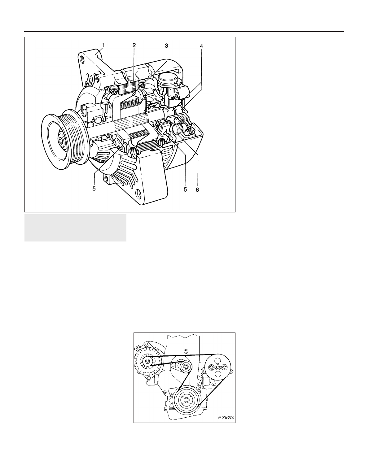
8 Alternator drivebelt -
removal, refitting and adjusting
2
V-belt type (not-ribbed)
Removal
1 Disconnect the air inlet trunking from the air
cleaner, and the air box or throttle body, as
applicable, and remove it for improved
access.
2 Correct tensioning of the drivebelt will
ensure that it has a long life. Beware,
however, of overtightening, as this can cause
excessive wear in the alternator.
3 The belt should be inspected regularly, and
if it is found to be worn, frayed or cracked, it
should be renewed as a precaution against
breakage in service. It is advisable to carry a
spare drivebelt of the correct type in the
vehicle always.
4 On models with power steering, the
alternator drivebelt also drives the power
steering pump.
5 To remove the belt, on 1.8 and 2.0 litre
models first remove the power steering pump
drivebelt, as described in Chapter 10.
6 Loosen the two alternator mounting nuts
and bolts sufficiently to allow the alternator to
be pivoted in towards the engine.
7 Slide the belt from the pulleys.
Refitting
8 Ensure that the correct type of belt is used,
if it is being renewed. Fit the belt around the
pulleys. Take up the slack in the belt by
swinging the alternator away from the engine
and lightly tightening the mounting nuts and
bolts.
Adjusting
9 Although special tools are available for
measuring the belt tension, a good
approximation can be achieved if the belt is
tensioned so that there is approximately 13.0
mm (0.5 in) of free movement under firm
thumb pressure at the mid-point of the
longest run between pulleys.
10 With the mounting bolts just holding the
unit, lever the alternator away from the engine
using a wooden lever at the mounting bracket
end until the correct tension is achieved. Then
tighten the mounting nuts and bolts. On no
account lever at the free end of the alternator,
as serious internal damage could be caused.
11 Where applicable, refit and tension the
power steering pump drivebelt, as described
in Chapter 10.
12 Refit the air inlet trunking.
13 When a new belt has been fitted, it will
probably stretch slightly when it is first run,
and the tension should be rechecked and if
necessary adjusted after approximately 250
miles (400 km).
Ribbed V-belt type
General
14 Later models equipped with power
steering are fitted with a ribbed V-belt type
drivebelt in conjunction with an automatic
tensioning roller. Once the belt is installed, no
further adjustment is necessary as the correct
tension is maintained by the automatic
tensioning roller. Removal and refitting
procedures are as follows.
Removal
15 For improved access, remove the air
cleaner assembly and air inlet trunking.
16 If the original drivebelt is to be refitted, mark
the rotational direction on the belt with chalk.
17 Using a spanner or socket on the
automatic tensioning roller hexagon, turn the
tensioning roller clockwise (as viewed from the
right-hand side of the car) and hold it in this
position. With the drivebelt tension released,
slip the drivebelt off the pulleys, then allow the
tensioner to return to its original position.
18 Support the engine under the sump with a
jack and interposed block of wood.
19 From under the car, unbolt the right-hand
engine mounting block from the body.
20 Lower the engine support jack just
sufficiently to allow the drivebelt to be
withdrawn from between the mounting block
and the body.
Refitting
21 Slip the new drivebelt between the
mounting block and body then raise the
engine, by means of the jack, to its original
position.
22 Clean the threads of the mounting block
retaining bolts, apply locking fluid, and refit
the bolts. Tighten the bolts to the specified
torque (see Chapter 2A).
23 Rotate the automatic tensioner roller anticlockwise and route the drivebelt around the
pulleys as shown (see illustration). With the
belt correctly positioned, release the tensioner
that will automatically apply the correct
tension to the belt.
24 On completion, refit the air cleaner
assembly and the air inlet trunking.
5•6 Engine electrical systems
7.5 Sectional view of the Delco-Remy
“compact” series alternator
1 Drive end bracket
2 Stator
3 Rotor
4 Slip rings
5 Fan
6 Rectifier
8.23 Correct routing of the ribbed V-belt
Page 94
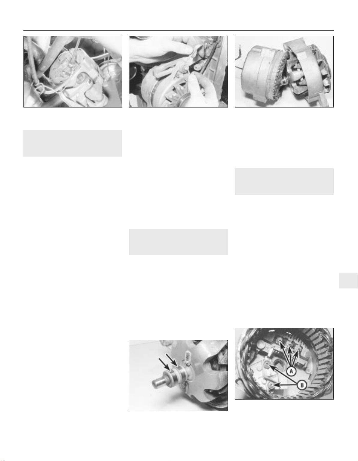
9 Alternator- removal and
refitting
3
Note: Refer to Section 3 before proceeding
Except ‘compact’ series
alternators
Removal
1 Disconnect the battery leads.
2 Disconnect the air trunking from the air
cleaner, and the air box or throttle body, as
applicable, and remove it for improved
access.
3 Disconnect the wiring plug, or disconnect
the wires from their terminals on the rear of
the alternator, noting their locations (see
illustration).
4 Remove the drivebelt, (Section 8).
5 Unscrew the two mounting bolts and nuts
and recover any washers and insulating
bushes, noting their locations. Note the earth
strap attached to the top mounting bolt (see
illustration).
6 Withdraw the alternator, taking care not to
knock or drop it, as this can cause irreparable
damage.
Refitting
7 Refitting is a reversal of removal,
remembering the following points.
8 Ensure that the earth lead is in place on the
top mounting bolt.
9 Refit and tension the drivebelt, (Section 8).
‘Compact’ series alternators
Removal
10 Disconnect the battery negative lead.
11 Remove the air inlet trunking and, if
necessary for improved access, the air
cleaner assembly.
12 Mark the rotational direction on the
alternator drivebelt with chalk.
13 Using a spanner or socket on the
automatic tensioning roller hexagon turn the
tensioning roller clockwise (as viewed from
the right-hand side of the car) and hold it in
this position. With the drivebelt tension
released, slip the drivebelt off the alternator
pulley, then allow the tensioner to return to its
original position.
14 Disconnect the electrical cable
connections at the rear of the alternator.
15 Undo and remove the alternator lower
mounting bolt, and slacken both upper bolts
that secure the alternator mounting brackets
to the engine.
16 Undo and remove both bolts that secure
the alternator to its mounting brackets, noting
the location of the different length bolts.
Swing the brackets clear and remove the
alternator from the engine.
Refitting
17 Refitting is a reversal of removal. Tighten
the mounting bolts to the specified torque,
and refit the drivebelt as described in
Section 8.
10 Alternator - testing
5
Due to the specialist knowledge and
equipment required to test or service an
alternator, it is recommended that if a fault is
suspected, the vehicle is taken to a dealer or a
specialist. Information is limited to the
inspection and renewal of the brushes.
Should the alternator not charge, or the
system be suspect, the following points may
be checked before seeking further assistance:
a) Check the drivebelt tension, as described
in Section 8
b) Check the condition of the battery and its
connections - see Section 5
c) Inspect all electrical cables and
connections for condition and security
Note that if the alternator is found to be
faulty, it may prove more economical to buy a
factory-reconditioned unit, rather than having
the existing unit overhauled.
11 Alternator brushes - removal,
inspection and refitting
3
Removal
Delco-Remy type (except ‘compact’
series)
1 Remove the alternator, as described in
Section 9
2 Scribe a line across the drive end housing
and the slip ring end housing, to ensure
correct alignment when reassembling.
3 Unscrew the three through-bolts, and prise
the drive end housing and rotor away from the
slip ring end housing and stator (see
illustration).
4 Check the condition of the slip rings, and if
necessary clean with a rag or very fine glass
paper (see illustration).
5 Remove the three nuts and washers
securing the stator leads to the rectifier, and
lift away the stator assembly (see
illustration).
Engine electrical systems 5•7
11.3 Separating the drive end housing
from the slip ring end housing - Delco-
Remy alternator
11.4 Alternator slip rings (arrowed) Delco-Remy alternator
11.5 Delco-Remy alternator
A Stator lead securing nuts
B Brush holder/voltage regulator
securing screws
9.5 Disconnecting the earth lead from the
top alternator mounting bolt
9.3 Disconnecting the wires from the
terminals on the rear of the alternator -
Delco-Remy alternator
5
Page 95
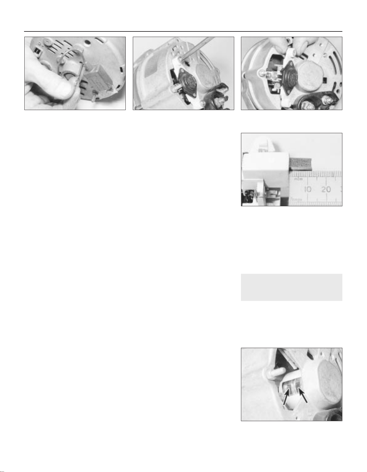
6 Remove the terminal screw and lift out the
diode assembly.
7 Extract the two screws securing the brush
holder and voltage regulator to the slip ring
end housing, and remove the brush holder
assembly. Note the insulation washers under
the screw heads.
8 Check that the brushes move freely in their
guides, and that the brush lengths are within
the limits given in the Specifications. If any
doubt exists regarding the condition of the
brushes, the best policy is to renew them.
9 To fit new brushes, unsolder the old brush
leads from the brush holder, and solder on the
new leads in exactly the same place.
10 Check that the new brushes move freely
in the guides.
Refitting
11 Before refitting the brush holder
assembly, retain the brushes in the retracted
position using a stiff piece of wire or a twist
drill.
12 Refit the brush holder assembly so that
the wire or drill protrudes through the slot in
the slip ring end housing, and tighten the
securing screws.
13 Refit the diode assembly and the stator
assembly to the housing, ensuring that the
stator leads are in their correct positions, and
refit the terminal screw and nuts.
14 Assemble the drive end housing and rotor
to the slip ring end housing, ensuring that the
previously made marks are aligned. Insert and
tighten the three through-bolts.
15 Pull the wire or drill, as applicable, from
the slot in the slip ring end housing so that the
brushes rest on the rotor slip rings (see
illustration).
16 Refit the alternator, as described in
Section 9
Bosch type alternator
Removal
17 Disconnect the air trunking from the air
cleaner, and the air box or throttle body, as
applicable, and remove it for improved
access.
18 Disconnect the battery leads.
19 If desired, to improve access further, the
alternator can be removed, as described in
Section 9
20 Remove the two securing screws, and
withdraw the brush holder/voltage regulator
assembly (see illustrations).
21 Check that the brushes move freely in
their guides, and that the brush lengths are
within the limits given in the Specifications
(see illustration). If any doubt exists
regarding the condition of the brushes, the
best policy is to renew them as follows.
22 Hold the brush wire with a pair of pliers,
and unsolder it from the brush holder. Lift away
the brush. Repeat for the remaining brush.
Refitting
23 Note that whenever new brushes are
fitted, new brush springs should also be fitted.
24 With the new springs fitted to the brush
holder, insert the new brushes, and check that
they move freely in their guides. If they bind,
lightly polish with a very fine file or glass
paper.
25 Solder the brush wire ends to the brush
holder, taking care not to allow solder to pass
to the stranded wire.
26 Check the condition of the slip rings, and
if necessary clean with a rag or very fine glass
paper (see illustration).
27 Refit the brush holder/voltage regulator
assembly, and tighten the securing screws.
28 Where applicable, refit the alternator, as
described in Section 9
29 Reconnect the battery leads.
30 Refit the air trunking.
Delco-Remy “compact” series
Removal
31 Remove the alternator as described in
Section 9.
32 Remove the plastic cover from the rear of
the alternator.
33 Undo the two bolts securing the brush
holder to the rear of the alternator, noting that
one of the bolts also secures the suppression
capacitor.
34 Remove the suppression capacitor then
withdraw the brush holder, noting the flat plug
on the side.
35 Check that the brushes move freely in
their holder and that the brush lengths are
within the limits given in the Specifications. If
any doubt exists regarding the condition of
the brushes, the best policy is to renew them.
36 Check the condition of the slip rings, and
if necessary clean with a rag or very fine glass
paper.
Refitting
37 Refitting the brushes is a reversal of
removal.
12 Starter motor - general
1 The starter motor is mounted at the rear of
the cylinder block, and may be of either
Delco-Remy or Bosch manufacture. Both
makes are of the pre-engaged type, i.e. the
drive pinion is brought into mesh with the
starter ring gear on the flywheel before the
main current is applied.
5•8 Engine electrical systems
11.15 Withdrawing the twist drill used to
retain the brushes -
Delco-Remy alternator
11.20B . . .and withdraw the brush
holder/voltage regulator assembly - Bosch
alternator
11.26 Alternator slip rings (arrowed) Bosch alternator
11.21 Measuring the length of an
alternator brush - Bosch alternator
11.20A Remove the securing screws . . .
Page 96
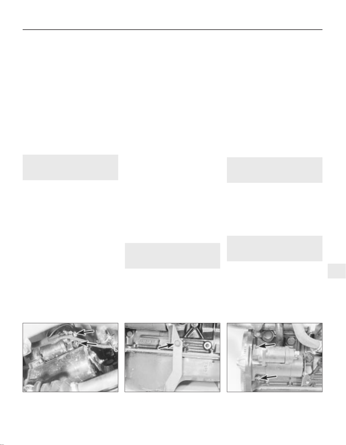
2 When the starter switch is operated, current
flows from the battery to the solenoid that is
mounted on the starter body. The plunger in
the solenoid moves inwards, so causing a
centrally pivoted lever to push the drive pinion
into mesh with the starter ring gear. When the
solenoid plunger reaches the end of its travel,
it closes an internal contact and full starting
current flows to the starter field coils. The
armature is then able to rotate the crankshaft,
so starting the engine.
3 A special freewheel clutch is fitted to the
starter driven pinion, so that when the engine
fires and starts to operate on its own it does
not drive the starter motor.
4 When the starter switch is released, the
solenoid is de-energised, and a spring moves
the plunger back to its rest position. This
operates the pivoted lever to the withdraw the
drive pinion from engagement with the starter
ring.
13 Starter motor - testing
3
Note: Refer to Section 3 before proceeding
Testing
1 If the starter motor fails to turn the engine
when the switch is operated, and engine
seizure is not the problem, there are several
other possible reasons:
a) The battery is faulty
b) The electrical connections between the
switch, solenoid battery and starter motor
are somewhere failing to pass the
necessary current from the battery
through the starter to earth
c) The solenoid switch is faulty
d) The starter motor is mechanically or
electrically defective
e) The starter motor pinion and/or flywheel
ring gear is badly worn, and in need of
replacement
2 To check the battery, switch on the
headlamps. If they dim after a few seconds,
then the battery is in a discharged state. If the
lamps glow brightly, operate the starter switch
and see what happens to the lamps. If they
dim, then power is reaching the motor, but
failing to turn it. If the starter turns slowly, go
on to the next check.
3 If, when the starter switch is operated, the
lamps stay bright, then insufficient power is
reaching the motor. Disconnect the battery
and the starter/solenoid power connections,
and the engine earth strap, then thoroughly
clean them and refit them. Smear petroleum
jelly around the battery connections to
prevent corrosion. Corroded connections are
the most frequent cause of electrical system
malfunctions.
4 If the preceding checks and cleaning tasks
have been carried out without success, a
clicking noise will probably have been heard
each time the starter switch was operated.
This indicates that the solenoid switch was
operating, but it does not necessarily follow
that the main contacts were closing properly
(if no clicking has been heard from the
solenoid, it is certainly defective). The
solenoid can be checked by connecting a
voltmeter across the main cable connection
on the solenoid and earth. When the switch is
operated, these should be a reading on the
voltmeter. If there is no reading, the solenoid
unit is faulty, and should be renewed.
5 If the starter motor operates, but does not
turn the engine, then it is likely that the starter
pinion and/or flywheel ring gear are badly
worn. If this is the case, the starter motor will
normally be noisy in operation.
6 Finally, if it is established that the solenoid
is not faulty, and 12 volts are reaching the
starter, then the motor itself is faulty, and
should be removed for inspection.
14 Starter motor - removal and
refitting
3
Note: Refer to Section 3 before proceeding
Removal
1 Disconnect the battery negative lead.
2 Apply the handbrake, then jack up the front
of the vehicle, and support securely on axle
stands (see “Jacking and Vehicle Support”)
positioned under the body side members.
3 On DOHC models, remove the engine
undershield, as described in Chapter 11.
4 Note the wiring connections on the
solenoid, then disconnect them (see
illustration).
5 Where applicable, unscrew the bolt
securing the exhaust bracket and the starter
motor mounting bracket to the cylinder block
(see illustration).
6 Unscrew the two starter motor mounting
bolts. Note that the top bolt on some models
are fitted from the transmission side, and
secures a wiring harness bracket (see
illustration).
7 Withdraw the starter motor.
Refitting
8 Refitting is a reversal of removal, but where
applicable, ensure that the wiring harness
bracket is in place on the top mounting bolt,
and tighten all bolts to the specified torque.
15 Starter motor - overhaul
5
If the starter motor is thought to be suspect,
it should be removed from the vehicle and
taken to an auto-electrician for testing. Most
auto-electricians will be able to supply and fit
brushes at a reasonable cost. However, check
on the cost of repairs before continuing as it
may prove more economical to obtain a new
or exchange motor.
16 Ignition coil - removal, testing
and refitting
3
Note: Refer to Section 3 before proceeding.
An ohmmeter will be required to test the coil
Removal
1 The ignition coil is either a cylindrical metal
canister or a moulded plastic unit. It is
clamped or bolted to the left-hand inner wing
panel, near the suspension strut top mounting
(under the power steering fluid reservoir, on
Engine electrical systems 5•9
14.6 Starter motor securing bolts
(arrowed) - 1.6 litre model
(engine removed)
14.5 Starter motor mounting
bracket/exhaust bracket securing bolt
(arrowed) - 1.6 litre model
14.4 Starter motor and solenoid viewed
from underneath the vehicle. Solenoid
wiring connections arrowed
5
Page 97
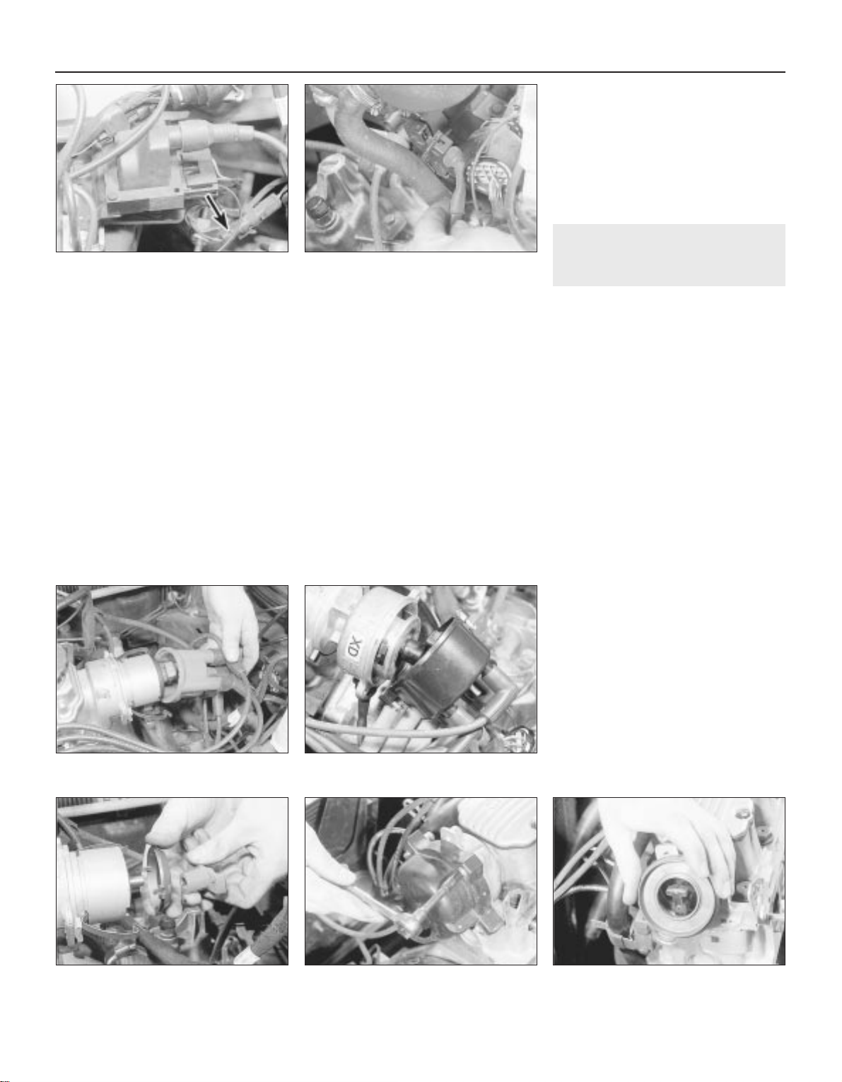
models so equipped). On 14 NV, 16 SV and
18 SV models, the ignition amplifier module is
mounted on the coil’s bracket or baseplate
(see illustration).
2 Disconnect the battery negative lead.
3 Carefully note the LT wiring connections
before disconnecting them (see illustration).
4 Note that on models with power steering,
one of the coil securing bolts also secures the
power steering fluid reservoir bracket.
5 Remove the coil.
6 On models with a cylindrical type coil, the
mounting clamp can be removed from the coil
by loosening the clamp nut.
Testing
7 To test the coil, first disconnect the LT
wiring and the HT lead. Test the coil’s primary
windings by connecting a multi-meter across
the LT terminals (“+” or “15” and “-” or “1”).
Then the secondary windings by testing
across the HT terminal (“4”) and one of the LT
terminals (usually the “-/1” terminal, although
in some cases, either terminal may serve). On
20 XEJ models, results should closely
approximate the specified values. On all other
models, typical primary resistances are less
than 1 ohm, while secondary resistances can
be expected to be in the 4000 to 12 000 ohms
range.
8 If the results obtained differ significantly
from those given, showing windings that are
shorted or open circuit, the coil must be
renewed.
Refitting
9 Refitting is a reversal of removal, however
ensure correct connections. Usually they are
physically different to prevent incorrect
refitting. If not, use the terminal marks or
numbers in conjunction with the relevant
wiring diagram at the back of this manual to
ensure that the connections are correctly
remade. If the connections are reversed, so
will the coil’s polarity be. While the engine
may still run, spark plug life will be reduced
and poor starting and/or misfiring may follow.
10 Where applicable, ensure that the coil
suppresser is in position before refitting the
coil securing bolts.
17 Distributor cap and rotor
arm - removal and refitting
3
Note: Refer to Section 3 before proceeding
Removal
14 NV and 16 SV models
1 Disconnect the battery negative lead.
2 Identify each HT lead for position, so that
the leads can be refitted to their correct
cylinders, then disconnect the leads from the
spark plugs by pulling on the connectors, not
the leads. Similarly, disconnect the HT lead
from the coil. Pull the leads from the clips on
the camshaft cover.
3 On the Bosch distributor, prise away the
two spring clips with a screwdriver, and lift off
the distributor cap. On the Lucas distributor,
unscrew the two small bolts and lift off the
cap (see illustrations).
4 The rotor arm is a push fit on the end of the
distributor shaft.
5 If needed, on the Bosch distributor, the
plastic shield can be pulled from the end of
the distributor, to allow examination of the
distributor components (see illustration).
Other models, where applicable
6 Proceed as described in paragraphs 1 and 2.
7 On DOHC models (except X20 XEV),
unscrew the two securing bolts and withdraw
the spark plug cover from the camshaft cover.
8 Using a Torx socket, unscrew the three
captive securing screws and withdraw the
distributor cap (see illustration).
9 Withdraw the plastic shield from the rotor
arm housing. The shield is fitted in the
housing, with an O-ring seal located in a
groove in its periphery. Ease out the shield,
taking care not to damage the rotor arm (see
illustration).
5•10 Engine electrical systems
16.1 Ignition coil - 1.6 litre models - note
ignition timing basic adjustment coding
plug (arrowed)
17.3A Removing the distributor cap -
1.6 litre model (Bosch distributor) . . .
17.9 Removing the plastic shield from the
rotor arm housing - 2.0 litre model
17.8 Unscrewing a distributor cap
securing screw - 2.0 litre model
17.5 Removing the rotor arm and plastic
shield - 1.6 litre model (Bosch distributor)
17.3B . . .and 1.6 litre models (Lucas
distributor)
16.3 Disconnecting the coil LT wiring plug
- 2.0 litre model
Page 98
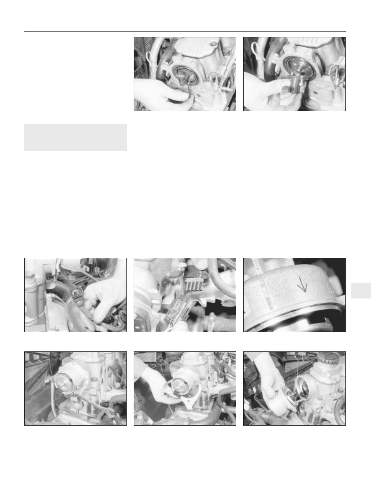
10 Using an Allen key or hexagon bit, extract
the two securing screws and withdraw the
rotor arm, leaving the metal rotor hub in the
housing (see illustrations).
11 Examine the O-ring on the plastic shield,
and renew if necessary.
Refitting
12 Refitting is a reversal of removal, noting
that the rotor arm can only be fitted in one
position. If necessary, turn the metal rotor hub
so that the screw holes align with those in the
rotor arm and the end of the camshaft. Ensure
that the HT leads are correctly reconnected.
18 Distributor (SOHC models) -
removal and refitting
3
Note: Refer to Section 3 before proceeding. A
tachometer and a timing light will be required
to check the ignition timing on completion 14
NV and 16 SV
Removal
1 Disconnect the battery negative lead.
2 Remove the distributor cap, as described in
Section 17.
3 Disconnect the distributor wiring plug (see
illustrations).
4 On 14 NV models, disconnect the vacuum
pipe from the diaphragm unit on the side of
the distributor.
5 If the original distributor is to be refitted,
make alignment marks between the
distributor body and the camshaft housing, so
that the distributor can be refitted in its
original position.
6 Turn the crankshaft. This can be done by
either using a socket or spanner on the
crankshaft pulley bolt, or by engaging top
gear and pushing the vehicle backwards or
forwards. Bring No 1 cylinder to the firing
point. No 1 cylinder is at the firing point when:
a) The relevant timing marks are aligned. On
14 NV models, the pointer on the rear
timing belt cover should be aligned
halfway between the two notches in the
crankshaft pulley. On 16 NV models, the
pointer on the rear timing belt cover
should be aligned with the notch in the
crankshaft pulley
b) The tip of the rotor arm is pointing to the
position occupied by the No 1 cylinder HT
lead terminal in the distributor cap
c) On the Bosch distributor, the rotor arm is
aligned with the notch in the distributor
body (remove the rotor arm and plastic
shield, then refit the rotor arm to check
the alignment with the notch). On the
Lucas distributor, the rotor arm is
approximately aligned with the TDC arrow
stamped in the distributor body (see
illustration).
7 Unscrew the clamp nut and remove the
clamp plate, then withdraw the distributor
from the camshaft housing (see illustrations).
8 If desired, the distributor can be
dismantled, as described in Section 20.
9 Check the condition of the O-ring on the
rear of the distributor body, and renew if
necessary.
Refitting
10 Begin refitting by checking that No 1
cylinder is still at the firing point. The relevant
timing marks should be aligned. If the engine
has been turned whilst the distributor has
Engine electrical systems 5•11
18.6 TDC arrow on the Lucas distributor
body
18.7C . . .and withdraw the distributor18.7B . . .remove the clamp plate . . .18.7A Unscrew the clamp nut . . .
18.3B Disconnecting the distributor wiring
on the C16 NZ engine
18.3A Disconnecting the distributor wiring
plug - 1.6 litre model (Bosch distributor)
17.10B . . .and withdraw the rotor arm -
2.0 litre model
17.10A Extract the two securing
screws . . .
5
Page 99
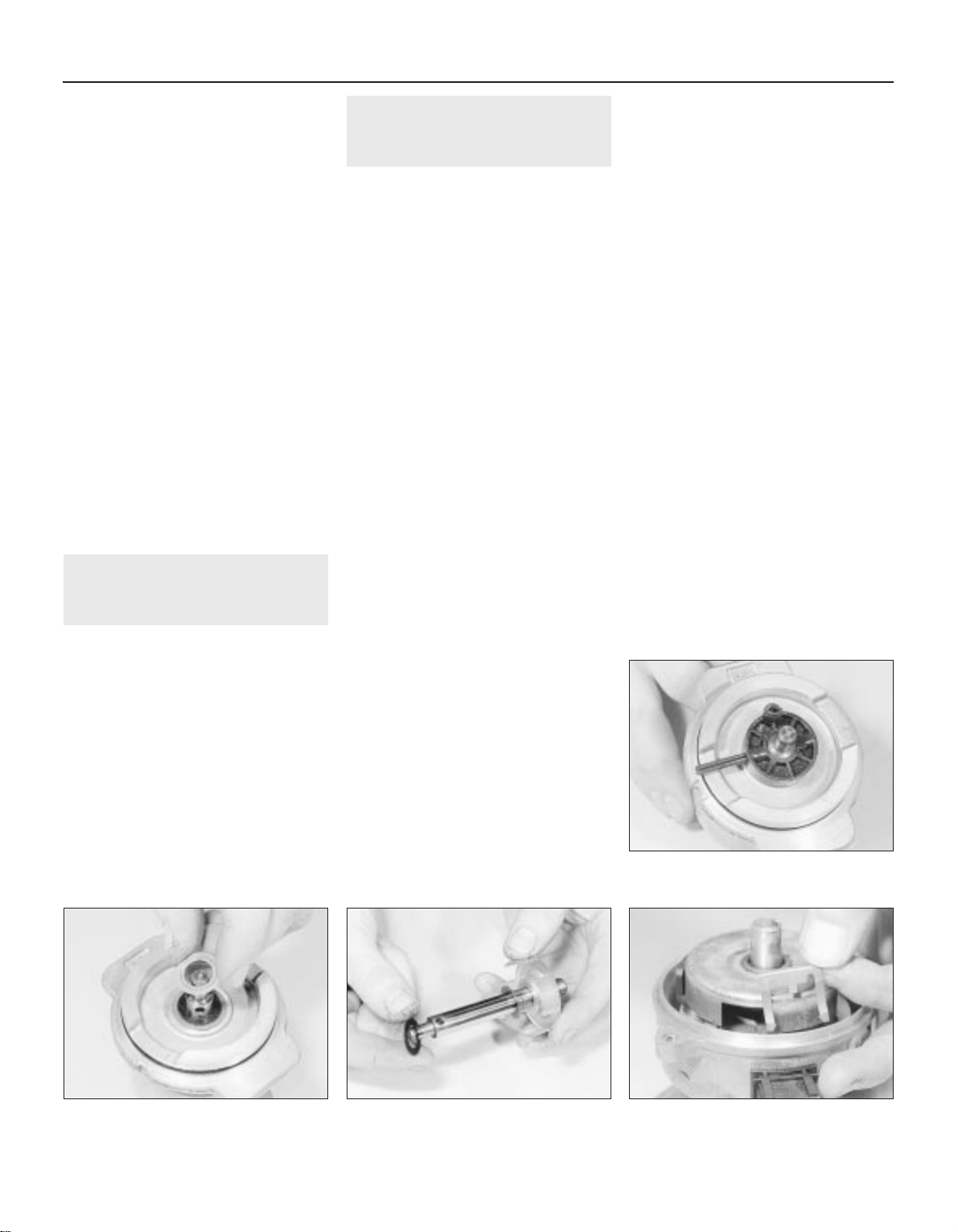
been removed, check that No 1 cylinder is on
its firing stroke by removing No 1 cylinder
spark plug and placing a finger over the plug
hole. Turn the crankshaft until compression
can be felt, which indicates that No 1 piston is
rising on its compression stroke. Continue
turning the crankshaft until the relevant timing
marks are in alignment.
11 Turn the rotor arm to the position noted in
paragraph 6c, and hold the rotor arm in this
position as the distributor is fitted. Note that
the distributor driveshaft will only engage with
the camshaft in one position. If the original
distributor is being refitted, align the marks
made on the distributor body and camshaft
housing before removal.
12 Refit the clamp plate and nut, but do not
fully tighten the nut at this stage.
13 On the Bosch distributor, remove the rotor
arm, then refit the plastic shield and the rotor
arm.
14 On 14 NV models, reconnect the vacuum
pipe to the diaphragm unit.
15 Reconnect the distributor wiring plug.
16 Refit the distributor cap as described in
Section 17.
17 Reconnect the battery negative lead.
18 Check and if necessary adjust the ignition
timing, as described in Section 21.
19 Distributor (DOHC models),
where applicable - removal
and refitting
3
Removal
1 Disconnect the battery negative lead.
2 Remove the distributor cap, as described in
Section 17.
3 Disconnect the distributor wiring plug.
4 Unscrew the two securing bolts, and
remove the distributor from the cylinder head.
5 Examine the O-ring on the rear of the
distributor, and renew if necessary.
Refitting
6 Refitting is a reversal of removal. However,
note that the distributor should be fitted so
that the wiring plug is positioned on the upper
left-hand side of the distributor body, when
viewed from the distributor cap end.
20 Distributor - dismantling,
inspection and reassembly
3
Note: Before contemplating dismantling of a
distributor, check the cost and availability of
replacement parts. It may prove more
economical to renew the complete distributor
assembly
14 NV models
Dismantling
1 With the distributor removed as described
in Section 18, continue as follows.
2 Pull off the rotor arm, and remove the
plastic shield.
3 The top bearing plate can be removed after
unscrewing the two securing screws, however
(other than the vacuum diaphragm unit), no
spares are available for the distributor and no
adjustments are required.
4 If desired, the vacuum diaphragm unit can
be removed by extracting the two securing
screws and unhooking the operating arm from
the distributor baseplate. Note that the
screws are of differing lengths, the longer
screw also secures one of the distributor cap
clips.
Inspection
5 The vacuum unit can be tested by applying
suction to the vacuum port, and checking that
the operating rod moves into the unit as
suction is applied. Remove the suction, and
check that the operating rod returns to its
original position. If the operating rod does not
move as described, renew the vacuum unit.
6 Check the distributor cap for corrosion of
the segments, and for signs of tracking,
indicated by a thin black line between the
segments. Make sure that the carbon brush in
the centre of the cap moves freely and stands
proud of the surface of the cap. Renew the
cap if necessary.
7 If the metal portion of the rotor arm is badly
burnt or loose, renew it. If slightly burnt or
corroded; it may be cleaned with a fine file.
8 Examine the seal ring at the rear of the
distributor body, and renew if necessary.
Reassembly
9 Reassembly is a reversal of dismantling,
ensuring that the vacuum unit operating arm
is correctly engaged with the peg on the
baseplate, several attempts may be required
to reconnect it.
10 Refit the distributor as described in
Section 18, and then check and if necessary
adjust the ignition timing, as described in
Section 21.
16 SV models
Dismantling
11 With the distributor removed as described
in Section 18, pull off the rotor arm and, on
the Bosch distributor, remove the plastic
shield.
12 Using a pin punch, carefully drive out the
roll pin securing the plastic drive collar to the
rear of the distributor shaft (see illustration).
13 Lift off the drive collar, and remove the
thrustwashers from the end of the shaft (see
illustration).
14 Withdraw the shaft, complete with the
trigger vane, from the distributor body, and
recover the thrustwashers from the shaft (see
illustration).
15 On the Lucas distributor, extract the
spring clip from inside the body, then
withdraw the terminal block. Pull the small
wiring plug from inside the terminal block (see
illustrations).
16 Remove the screws, and lift the sensor
plate from the distributor body (see
illustrations).
5•12 Engine electrical systems
20.15A Removing the spring clip . . .20.14 Recovering the thrustwashers from
the shaft - 1.6 litre (Bosch distributor)
20.13 Removing the thrustwashers
20.12 Removing the drive collar roll pin -
1.6 litre models (Bosch distributor)
Page 100
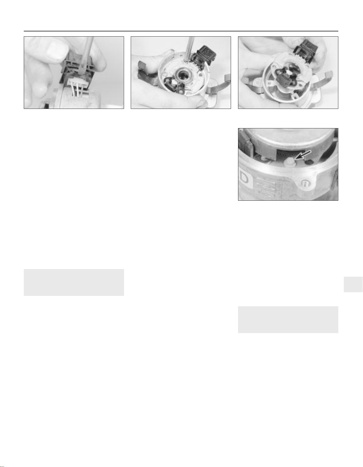
Inspection
17 Examine the distributor cap and rotor arm,
as described in paragraphs 6 and 7. Examine
the O-rings at the rear of the distributor body,
and on the rear of the shaft, and renew if
necessary.
Reassembly
18 Reassembly is a reversal of dismantling,
ensuring that the thrustwashers are correctly
located. Note that the drive collar should be
refitted so that the drive peg on the collar is
aligned with the groove in the top of the
distributor shaft (it is possible to fit the drive
collar 180° out of position).
19 Refit the distributor as described in
Section 18, and then check and if necessary
adjust the ignition timing, as described in
Section 21.
DOHC models (where
applicable)
20 The distributor cap and rotor arm can be
examined as described in paragraphs 6 and 7.
21 Ignition timing - checking and
adjustment
4
Note: Refer to Section 3 before proceeding. A
tachometer and a timing light will be required
during this procedure. For details of ignition
timing adjustment required to operate vehicles
on unleaded petrol, refer to Section 22.
14 NV and 16 SV models
Checking
1 Start the engine and run it until it reaches
normal operating temperature, then switch
off.
2 On 14 NV models, disconnect the vacuum
pipe from the distributor vacuum diaphragm
unit.
3 On all models use a spanner applied to the
crankshaft pulley bolt to rotate the crankshaft
clockwise until the notch in the pulley’s
inboard rim aligns with the pointer protruding
from the oil pump housing. On 14 NV models,
where two notches (indicating 10° and 5°
BTDC respectively) are found, rotate the
crankshaft until the second notch (in the
direction of rotation - i.e. 5° BTDC) aligns. Use
white paint or similar to emphasise the pointer
and notch, to make them easier to see.
4 Connect a timing light to No 1 cylinder
(nearest the timing belt end of the engine) HT
lead, also a tachometer; follow the equipment
manufacturer’s instructions for connection.
5 Start the engine and allow it to idle - the
speed should be between 700 and 1000 rpm.
6 On 14 NV models, aim the timing light at the
pointer and check that it is aligned with the
crankshaft pulley notch.
7 On early 16 SV models, disconnect the
ignition timing basic adjustment coding plug.
This can be identified by a length of Black
wire joining Brown/Red and Brown/Yellow
wires in a connector plug clipped to the wiring
or heater/cooling system hoses beneath the
battery/ignition coil (see illustration, 16.1). This
causes the MSTS-i module to adopt its basic
adjustment mode, sending a constant firing
signal corresponding to 10° BTDC and
eliminating any advance below 2000 rpm. Aim
the timing light at the pointer and check that it
is aligned with the crankshaft pulley notch.
8 On later 16 SV, C 16 NZ and C 16 NZ2
models, the coding plugs are no longer fitted.
For accurate checking, special Vauxhall test
equipment must be used which causes the
MSTS module to adopt its basic adjustment
mode.
9 Without access to such equipment, it is
possible to check and adjust the ignition
timing, accurate results cannot be
guaranteed. Owners are therefore advised to
have this work carried out by a suitably
equipped Vauxhall dealer; at the very least,
make the initial setting yourself and then have
it checked as soon as possible.
10 If you do attempt to check the ignition
timing yourself, note that the fixed reference
mark is now an extended line embossed on
the timing belt lower outer cover.
Adjustment
11 If the notch and pointer are not aligned,
loosen the distributor clamp nut and turn the
distributor body slightly in the required
direction to align.
12 Tighten the distributor clamp nut, and
check that the notch and pointer are still
aligned.
13 Stop the engine, and disconnect the
timing light and tachometer.
14 On 16 SV models, reconnect the basic
adjustment coding plug. On 14 NV models,
reconnect the vacuum pipe to the distributor
vacuum diaphragm unit.
Other models
15 No adjustment of the ignition timing is
possible on 1.8 and 2.0 litre models, as the
adjustment is carried out automatically by the
electronic control module.
16 The ignition timing can be checked by a
Vauxhall dealer using specialist dedicated test
equipment, if a fault is suspected.
22 Ignition timing - adjustment
for use with unleaded petrol
3
14 NV models
1 All models with the 14 NV engine have the
ignition timing adjusted for use with 95 RON
unleaded petrol before they leave the factory,
and no further adjustment is required.
2 Leaded petrol (98 RON) can be used if
desired, with no adverse effects.
1.6, 1.8 and 2.0 SOHC models
Note: Models equipped with a catalytic
converter must be operated on 95 R0N
unleaded petrol at all times, and although an
octane coding plug may be fitted, it should
not be tampered with
3 Models, other than 14 NV, are equipped
with an octane coding plug, which is located
Engine electrical systems 5•13
20.16B . . .and withdraw the sensor plate -
1.6 litre (Bosch distributor)
20.16C Sensor plate screw (arrowed) -
1.6 litre (Lucas distributor)
20.16A Remove the securing screws . . .20.15B . . .and disconnecting the small
wiring plug - 1.6 litre (Lucas distributor)
5
 Loading...