

Page 1

VAUXHALL Astra
Owner’s Manual
Page 2

Data specific to your vehicle
Please en t er yo u r veh icle ’s dat a he re to ke ep it ea sily acces sib le.
This information is available under the section "Technical da ta " as we ll as on the identification plate.
Fuel
Designation
Engine oil
Grade
Viscosity
Tyre inflation pr essure
Ty re si ze wi th up to 3 persons wi th full lo ad
Sum mer tyres Front Rear Front R ear
Winter tyres Front Rear Front R ear
Weights
Permissible gross vehicle weig ht
– EC kerb weight
=Loading
0
Page 3

Your Astra
Develope d to the la test findings of vehic le research, it offers technical sophistication and exceptional comfort.
Your vehicle represents an ideal synthesis of ad vanced technology, outstanding safety, environmental compatibility and e conomy in
opera tion.
It now lie s with you to drive your vehicle safely and to s ee it pe rforms pe rfectly.
This Owner's Manual provides you with all the necessary information to that end.
Th e Owner's M anual s h ould a lways be ke pt i n the v ehicle: ready to h and i n the g love co m part ment.
Make u se of the Owner's Manual:
z Its “I n Brief” section will give y ou an initial overview.
z Its inde x will help you find what y ou want.
z It will familiarize you with the sophisticated technology.
z It will increase your pleasure in y our vehicle.
z It will help you to handle your vehicle ex pertly.
The Owner's Manual is de signed to be clearly laid-out and easily understood.
This symbol:
6 signifies: continue re ading on n ext page.
3 The as terisk sig nifies equipment options not in all vehicles (model variants, engine options, models specific to one country, optional
equipment, Genuine Vauxhall Parts and Accessories).
Text highlighted in yellow in p artic ular indica tes possible risk of accident and
injury. Disregard of these notes can lead to injuries which may b e fatal. Vehicle
passengers must b e informed accordingly.
Yellow arrows in the illustrations serve as points of reference or indicate some action to be performe d.
Black arrows in the illustrations indicate a reaction or a second ac tion to be pe rform ed.
We wish you many hours of pleasurable driving
Your Vauxhall team
1
Page 4

2
Page 5

Contents
Commitment to customer
satisfaction:
Our ai m: to keep you happy with your
vehicle. All Vauxhall Dealerships offer first
class service at com petitive price s.
Experienced, factory tra ined te chnicians
work according to factory instructions.
Your dea lership can supply you with
GENUINE VAUXHALL APPROVED PARTS,
wh ic h ha ve u nd e rg o ne s tr in g e nt qu a l i t y
and prec ision checks and of course use ful
and attractive VAUXHALL APPROVED
AC CE SO R IES .
Our name is your guarantee!
For d eta ils of the
Vauxhall Deal ersh ip Net work
please ring this number 01582 - 427200
In b rie f . ......... ......... ......... ......... ......... ........ . 4
Instrument s ... ..... .... .... ..... .... ..... .... ..... .... .. 24
Keys, doors,
bonne t ... .... ......... .... ......... ..... ......... .... .. 5 0
S eats, in terio r ..... .... ......... ......... ......... ...... 6 3
S afety s ys tems ... .... ......... ......... ......... ...... 7 4
Ligh ting ..... .... ..... .... .... ..... .... ..... .... ..... .... 11 4
Win do ws, sun ro of .... ..... ......... ......... .... 11 9
C onve rtible foldin g t op .. ......... .... ..... .... 12 5
He ating an d v entilat ion ........ ......... .... 136
Air con ditioning system ......... .... ..... .... 14 1
Electronic
air co nditionin g s ys t em ...... ......... .... 148
Au tomatic transm ission ......... .... ..... .... 155
Driving hin ts . ..... .... ......... ......... ......... .... 16 0
S aving fuel ... ..... ........ ......... ......... ......... 162
Environ me ntal protection . ......... ......... 164
Fuel consum ption,
fuel, refuelling ... .... ......... ..... ......... .... 166
C atalytic co n ve r ter, e xh au st gases .... 168
Drive Contro l Sy stems ... ......... ......... .... 172
Brake s ... ......... ......... ......... ......... ......... .... 17 9
Wheels, tyres . ..... ........ ......... ......... ......... 182
Roof racks,
Carava n and trailer towin g ... ..... .... 186
S elf-h elp .... .... ......... .... ......... ..... ......... .... 193
If y ou have a pro blem ....... ......... ......... 226
Maintenance,
Inspection System ...... ......... ......... .... 228
Vehicle care .. ..... ........ ..... ......... .... ......... 239
Te chnical data . .... ......... ......... ......... .... 24 4
Inde x . ......... ......... ........ ......... ......... ......... 286
3
Page 6
In brief
Key numbers,
Code numbers
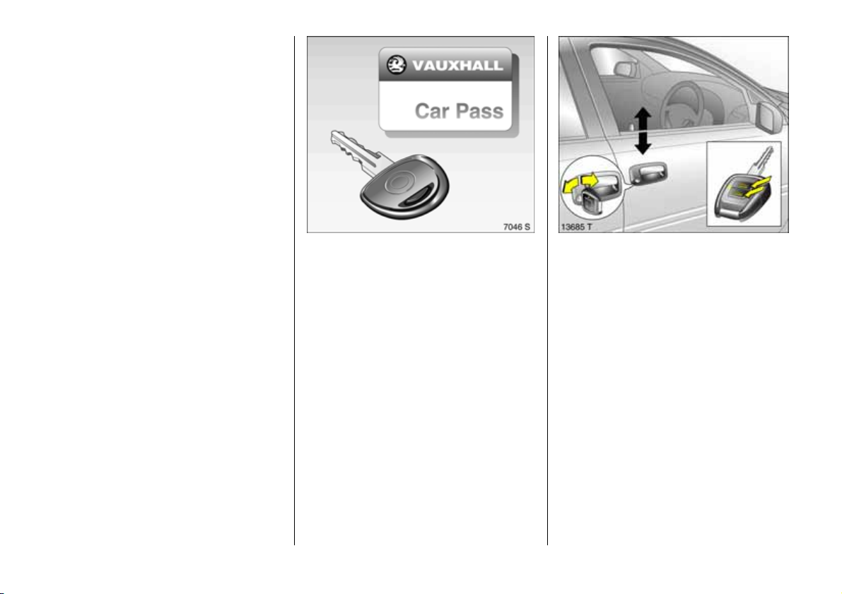
Remove key number from ke ys.
The key number is specified in the vehicle
documents and in the Car Pass 3.
Alloy whe els 3, towing e quip ment 3 : make
a note of the key identifier codes.
Elec tronic imm obiliser, Radio 3 : The c od e
numb ers are specified in the Car Pass and
Radio Pass 3 respectively.
Do not keep the Car Pass and Ra dio Pass in
the vehicle.
6 Further information, see pages 50, 51.
4
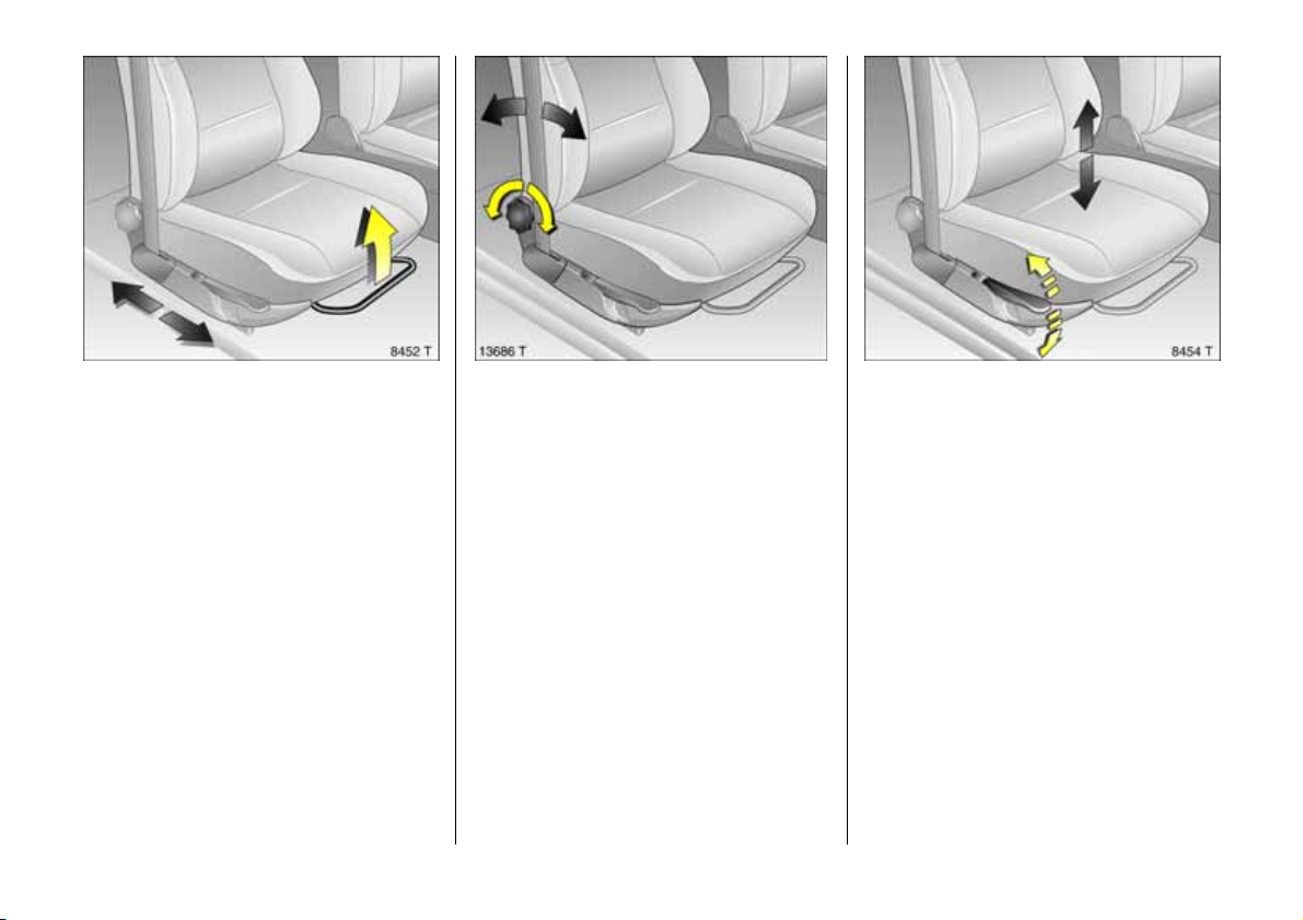
Unlocking the vehicle:
Turn key in
driver’s door lock and
raise door handle
Unlocking with radio remote control 3:
Point remote control a t vehicle,
press button q and raise door handle.
Locking from the inside: Press lock buttons.
6 Door lock s, child safety lock 3, see
pag e 50,
electronic immobilizer, see page 5 0,
radio remote control 3, see page 52,
central locking system 3 , see page 54,
anti-theft locking system 3, se e pa ge 56,
Vauxhall alarm system 3, see page 59,
convertible folding top 3, see page 1 25.
Page 7
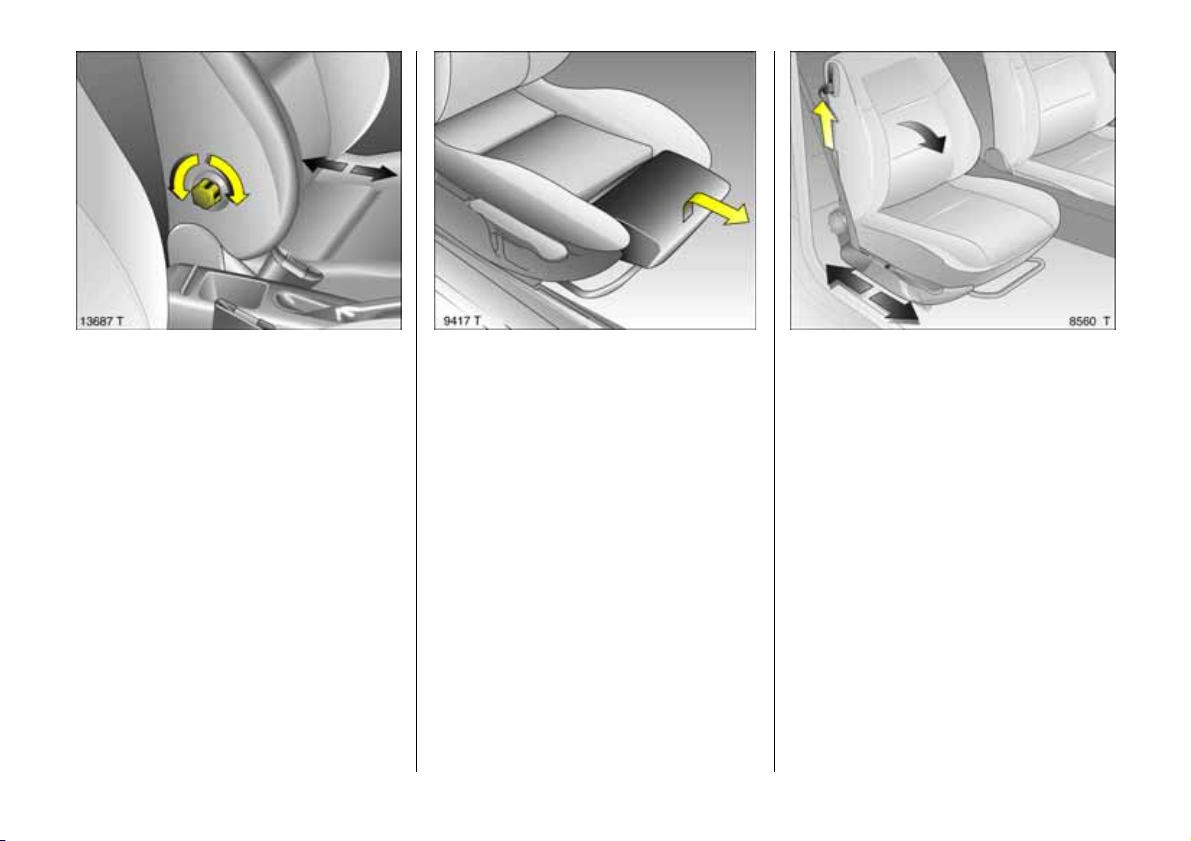
Seat adjustment:
Pu ll han dle,
slide s eat,
re lease han dle,
allow seat to audibly latch into
position
Never adjus t the driver's seat whilst driving.
It could m ov e in a n uncontrolled m anner
when the handle has been pulled.
6 Seat position, see page 63.
Adjusting the seat backrest:
Turn handw hee l
Move seat backrest to suit se ating position.
Do not lean on seat b ackrest whilst
adjusting it.
6 Seat position, see p age 63.
Adjusting the s eat height 3:
Le ver on ou tbo a rd s ide of seats
Pump direction of the lever
Up: Raises seat
Down: Lowers seat
6 Seat position, see page 63.
5
Page 8
Front seat lumbar support 3
adjustment:
Turn h a nd whe el
In the 3-door Ha tch, the Coupe and the
Convertible, the handwheel is on the
inboard side of the seat backrest; in the
4 door Saloon and 5-door Hatch and the
Estate, it is on the outboard side.
Adjust lumb ar support to suit personal
requirements.
Do not lean on sea t backre st whilst
adjusting it.
6 Seat position, see page 63.
6
Front seat thigh support 3
adj ust me nt :
Lift and slide the front thigh support
cu shi on
Do not adjust the thigh support whilst
driving.
6 Seat position, see p age 63.
Fo ldin g d o wn th e se at b a c kres ts 3:
Raise relea se le ve r
To facilitate entering a nd leaving the rea r
of t h e ve hicle, m ov e the f r o n t seat f orw ard
with its backrest folde d down.
Move seat ba ck, raise backrest and adjust
seat.
Seat with me mory function 3: W hen raising
backrest, push seat backwards with a light
pressure. It engages in its original position.
To stow luggage behind d riv er's seat, fold
down seat backre st: lift unlocking le ver,
mov e seat backre st forwards slightly,
r e le a se l eve r, f ol d b ac k re s t d ow n f u rth e r.
6 Seat position, see page 63.
Page 9
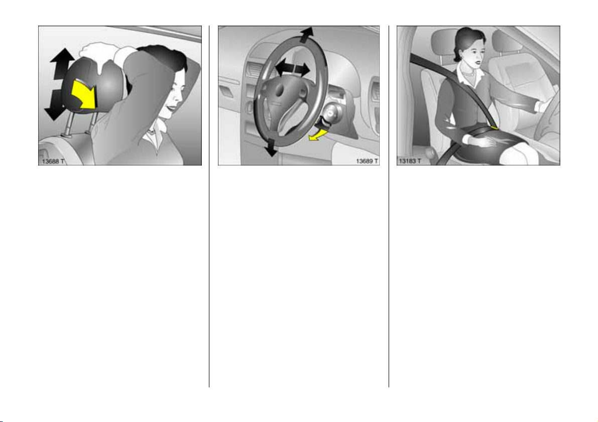
Adjusting head restraint height:
To release tilt forwards,
hold fir mly and adju st h eigh t,
then r ele ase
6 H ead restraint p osition, see page 6 3,
further information, removal, see page 64,
rear centre head restraint 3, see page 64.
Steering wh eel adjus tme nt 3:
Move lever down,
adjust height and distance,
move lever up,
engage
Ad jus t stee ri n g wheel only when ve hicle i s
stationary and ste ering colu mn lock is
re l ea s e d.
6 Airbag systems 3, see page 81.
Fi ttin g safe ty b e lt :
Smoothly pull seat belt from
inertia re el,
gu ide o ver the shoulder
and engage in buckle
The belt must not be twisted at any point.
The lap be lt must fit snugly across the
body . The seat backrest must not be
inclined too far back.
To re lease b elt, press red bu tton on belt
buckle.
6 Safety belts, see pages 75 to 79,
airbag systems 3, see pa ge 81 ,
seat position, see page 63.
7
Page 10
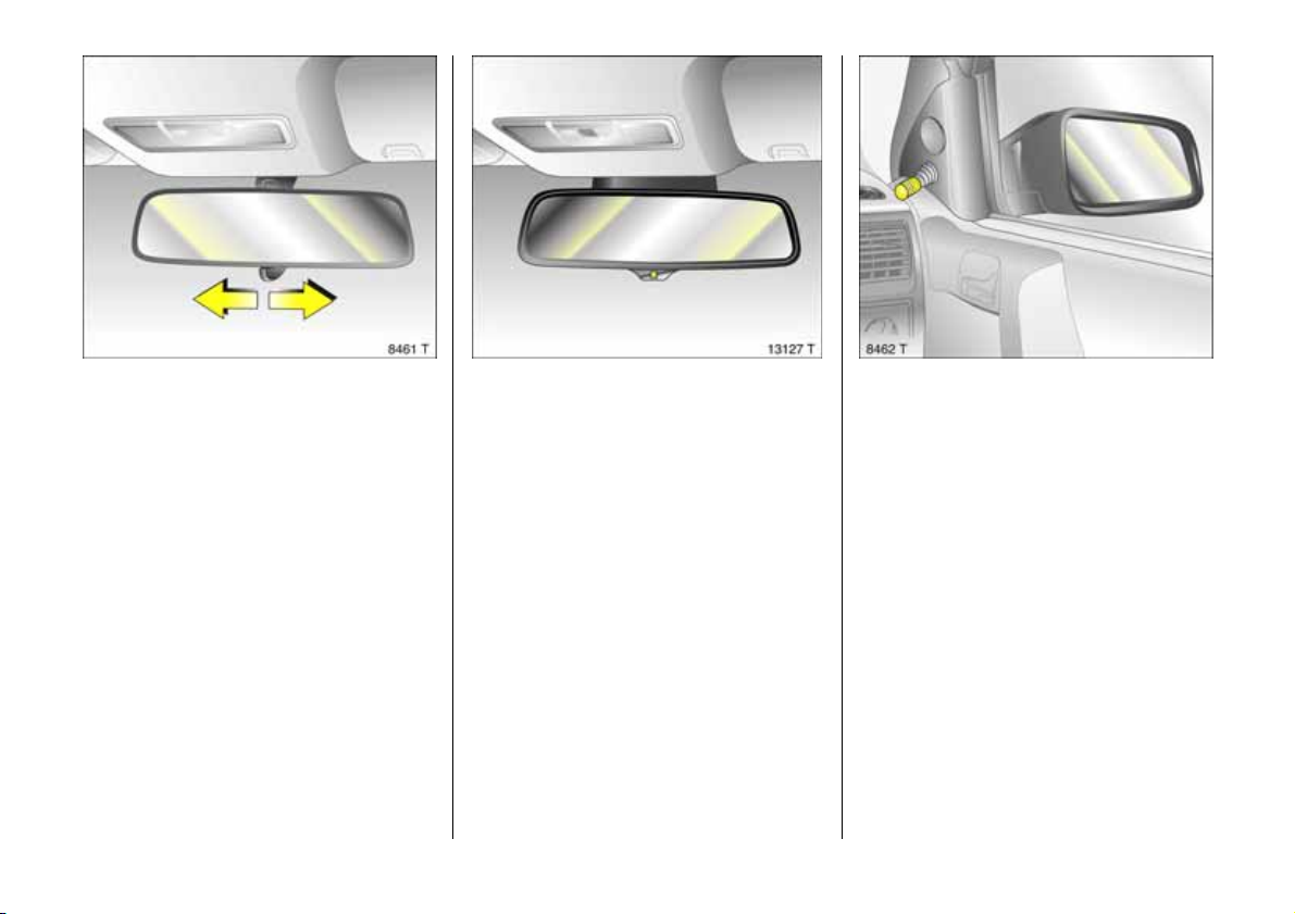
Adjusting interior m irror:
Swivel mirr or hous ing
Swivel lev er on underside of mirror housing
to red uce daz zle a t night.
8
Automatic anti-daz zle
interior mirror 3 adjustm ent:
Swivel in desired direction
Dazzle at night is automa tically reduced.
The mirror does not reduce dazzle when:
z the ignition is switched off
z rev erse gear is engaged or selector lever
set to R,
z interior lighting has been switched on.
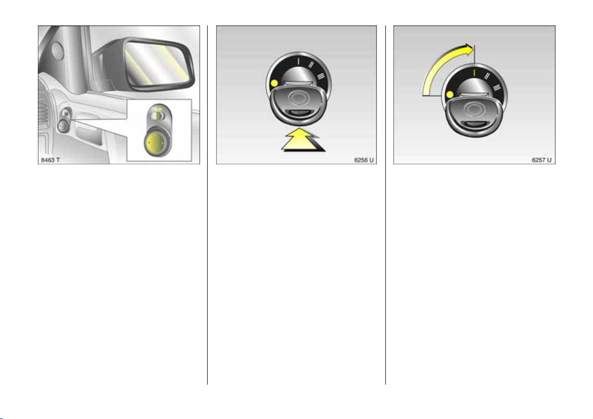
Exterior m irror adjustment:
Swivel in desired direction using
interior handle
6 Further information, aspherical exte rior
mirror 3, see page 113.
Page 11
Ele ctrically adjustable exterior
mirrors 3:
Fo ur-w a y sw itch in dr iv er ’s door
Toggle switch to le ft or right: four-wa y
switch moves a ppropriate mirror.
6 Further inform ation, aspherical
exterior mirror 3, se e page 11 3,
Heated exterior mirrors 3, s ee page 17.
St a rter sw i tch:
o =Ignition off
I = Steering unlocked, ignition off
II = Ignition on,
Diesel engines: preheating
III = Start (transmission in N eutral!)
6 Starting, see pa ge 20 ,
electronic immobiliser, see page 51.
Dise ngaging steering column lock:
To rel ease the lock,
mo ve t h e st eer in g whe el sli ght ly
and turn the key to position I
6 Removing key and e ngaging
stee ring whee l lo ck, s ee pag e 22.
9
Page 12
10
Page 13

Page
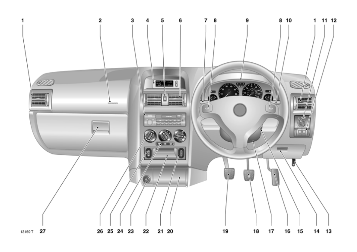
1 Side air v ents ... ..... ......... ........ ..1 3 8, 144
2 Front pa ssenger airbag 3 ......... .... . 8 1
3 Radio 3,
infotainmen t system 3 ..... .... ......... . 47
4 Display 3 for tim e, date,
outside temperature,
radio 3,
infotainmen t system 3 ,
check control 3,
trip computer 3 .... ......... ........ ......... . 3 2
5 Switch for hazard warning lamps . . 15
6 Centre air v en ts .... .... ..... 13 8 , 1 4 4, 150
7 Turn signals, hea dlamp flas h,
dippe d an d main be am ... .... ..... ..... 14
Cruise control 3 .... ......... ........ ......... 177
Trip computer 3 ... .... ......... .... ......... ..4 2
8 Horn .... ......... .... ......... ..... ........ ..... .... .. 1 5
9 Instru ments .. .... ......... ..... ........ ..... ..... 24
Pa ge
10 Windscreen wipers and wash
sy st e m, h ea d lamp w ash
sy ste m 3 and rear window wash
sy ste m 3 . .... ......... ......... ......... ......... ..1 6
11 Light s witch ..... ......... ........ ........ 1 4 , 1 1 4
12 Dim mer for
instrument illumination..... ..... ......... 116
Fog tail lamp ... ......... .... ......... .... ..... 1 1 5
Fog l am ps 3 .... ......... ........ ......... ..... 115
Headlamp ran ge adjustm ent 3 ... 114
13 Bonnet r ele ase lev er . ........ ......... ...... 62
14 Storage compartment, fuse box .. 209
15 Ignition switch
wit h ste ering whe el lock .. ..... ......... ... 9
16 Accele ra tor pedal .... ........ ..... 160, 161
17 Stee ring whee l adju stm ent 3 ... ..... ... 7
18 Brake peda l ......... ..... ........ ..... 160, 179
19 Clutch ped al .... .... ......... ......... ........ 1 6 1
20 Ashtray ... .... ..... .... ..... .... .... ..... .... ..... . 72
21 Electric window operation 3 ,
Con vertible ...... .... ......... .... ......... .... 120
Page
22 Storage compa rtm ent
23 Acce ssory socke t or
cigarette lighte r . ..... .... ......... ......... .. 72
24 Air re circulation s ys tem ... .... ......... 137
Air conditioning system 3 ... ..... .... 14 1
He ated rear w in dow ... .... 17, 140, 151
25 Convertible folding top
operation 3 .... .... ..... .... ..... .... ..... .... 130
26 He ating an d v entilat ion .. .... ......... 136
Electron ic air con ditioning
system 3 ..... ........ ......... ......... ......... . 148
27 Glove compartment ... ......... ......... .. 73
11
11
Page 14

Control indicators
? Automatic headlamp
range adjustment 3,
fault
se e p age 11 5.
v Airbag systems 3,
bel t tensioners,
see pages 76, 86.
X Seat belt 3,
see page 24.
R Brake system,
Clutch system ,
see page 25.
@ Electronic ally controlle d
engine cooli ng 3,
see page 25.
! Glow plugs 3,
see page 25.
A Engine electronics,
Imm obilizer 3,
Automat ic transmi ssion 3 ,
fault,
see pages 26, 51, 158, 170.
p Alternator,
see page 26.
Z Exhaust emission 3,
see page s 26, 170.
I O il press ure,
see page 2 7.
> Fog lamps 3,
see page s 27, 115.
P Main beam,
see page s 14, 27.
r Fog tail lamp,
see page s 27, 115.
O Turn signal l amps,
see page s 15, 27.
1 Autom atic transmission 3,
sporty driv ing pr og ramm e,
see page 1 56.
v Traction Control system 3,
Electronic St abili ty Progr am 3,
see page s 172, 174.
u Anti-lock brake system 3,
see page 1 81.
Y Fuel level,
see page s 28, 31, 193.
g Trailer turn signa l 3,
see page 28.
y Seat occup ancy recog nition 3,
see page 86.
Lig hting
Li ght s witc h,
st alk positions,
see pages 1 4, 114.
7 Lig h t s o ff,
8 Parking lamps,
9 Dipped and main beam.
0 Courtesy la mp,
see page 116.
> Fo g lamp s 3 ,
see page 115.
r Fog tail l amp,
see page 115.
k Instru me nt il luminati on,
see page 116.
? Headlamp range adjustment,
see page 114.
¨ Hazard w arning lamps,
see page 15.
12
Page 15

Heating, ventilation,
air c on dit io ning
autom ati c air conditio ni ng system 3
3,
x Air flow,
see pages 136, 142, 152.
Air distri bution,
see pages 137, 142, 151.
V To w i nd sc r e en an d
front door windows,
J To wind scre en , fr o n t
do or w i nd ow s
and footwell,
K To footwell,
L To head are a and footwell,
M To head are a.
Ü Heated rear window,
see pages 140, 146, 151.
4 Air circulation s ystem,
see pages 137, 143, 152.
n Air condit ioning system 3 ,
se e p age 14 1.
AUTO Automatic mode 3,
se e p age 14 9.
ECO Ope rati on without c o oling 3,
se e p age 15 1.
ß Heated seats 3,
see pages 140, 146, 154.
Su n ro of
l Sun roof 3
opening/lowering,
see page s 122, 124.
\ Sun roof 3
closing/raising,
see page s 122, 124.
Convertible folding top
, F olding t op 3
opening,
see page s 125, 130.
/ F o lding t op 3
closing,
see page s 126, 130.
Windsc re en w iper s
St alk p ositions,
see page 1 6,
§ O ff,
$ Timed interval wipe, or
autom atic wipe
with rain se nsor 3,
% Slow ,
& Fast.
Date, time, radio
Informa tion displa y 3 ,
see page 32.
Ö On button for date
and time ,
; Setting b uttons for date and time.
Steering wheel remote control 3,
see page 48.
Mi scellaneous
p Central l ocking sy s tem 3,
loc king – see pag e 54 .
q Central l ocking sy s tem 3,
unlocking – see page 54.
) Cigarette lighter,
see page 72.
j Horn,
see page 15.
/ Bonnet,
see page 62.
T Wi nter pro gra m ,
automa tic transm ission 3,
see page 157.
+ First Aid k it 3,
see pages 198, 20 0.
¨ Warnin g tri angle 3,
see pages 198, 20 0.
13
Page 16
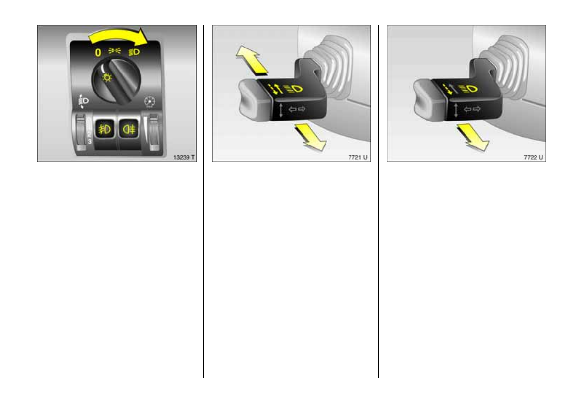
Light switch:
7 =Off
8 =Parking lamps
9 = Dipped or main beam
0 pull = Courtesy lamp
r Push = Fog tail lamp
> Press = Fog lamps 3
6 Further information, se e page 114,
Headlamp warning dev ic e, see pa ge 2 3,
Headlamp ra nge adjustment , see
pages 114, 115,
Daytime running lights, see pag e 114.
14
Main and dipped beam switch:
Main beam = Push lever forward
Dipped beam = Pull lever towards
steering wheel
By overcoming the lever resistance the
headlamp flash is opera ted.
Headlamp flash:
Pull stalk to wards steering wh eel
Page 17
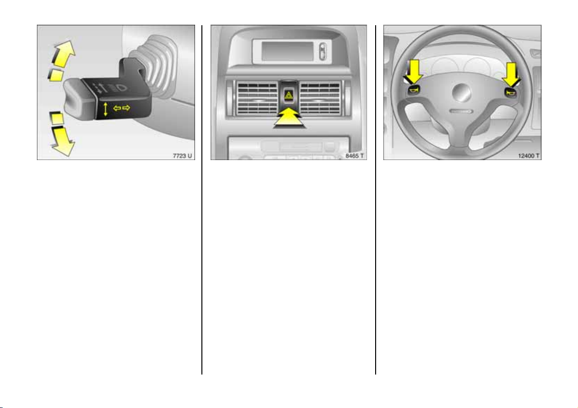
Operating turn signal lamps :
Lev e r in res t p o sitio n
right = up
le ft = down
W h en the stee rin g wh eel i s turne d ba ck, the
lever automatically returns to its original
position. This will not hap pen when making
a minor steering manoeuvre such as
changin g lane.
When lane chang ing, move lever to
res ista nce poi n t. W h en r e l eased , the le ver
will sprin g back.
Hazar d warn ing li gh ts :
On = Press ¨
Off = Press ¨ again
To aid location of the pushbutton, the red
surface is illuminated when the ignition
switched on. When the button is pressed,
its control indicator flashe s in time with the
ha zard warning lamps.
Horn:
Press j
6 Airbag systems 3, see page 81,
Steering wheel mounted remote control 3,
see page 4 8.
15
Page 18
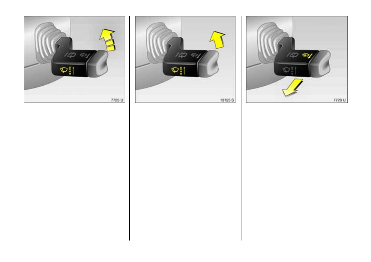
Windscreen wipers:
Move lever up
§ = Off
$ = Timed interval wipe
% = Slow
& = Fast
16
Automatic wiper with rain sensor
3 :
Move lever up
§ = O ff
$ = A uto ma tic wiper
w ith r a in senso r
% = S l ow ( co nst a nt )
& = F as t (c o nst ant )
Automatic wiping $: The rain sens o r
detects the amount of water on the
windscreen and automa tically regulates
the windscreen wipers.
Push lever down to switch off.
If necessary, the positions % or & can be
selected manually.
Operating windscreen and
headlamp wash systems 3 :
Pull stalk to wards steering wh eel
The wipers will swipe for a few strokes.
Th e he ad lamp was h sy ste m 3 can be
op e rated w hen the l igh ts are on.
On vehicles fitted with rain sensors 3 ,
op e rate th e win dscre en w ash s ys tem a t
regular intervals, to keep the sensor area
clean.
6 Further information, se e pages 236, 242.
Page 19
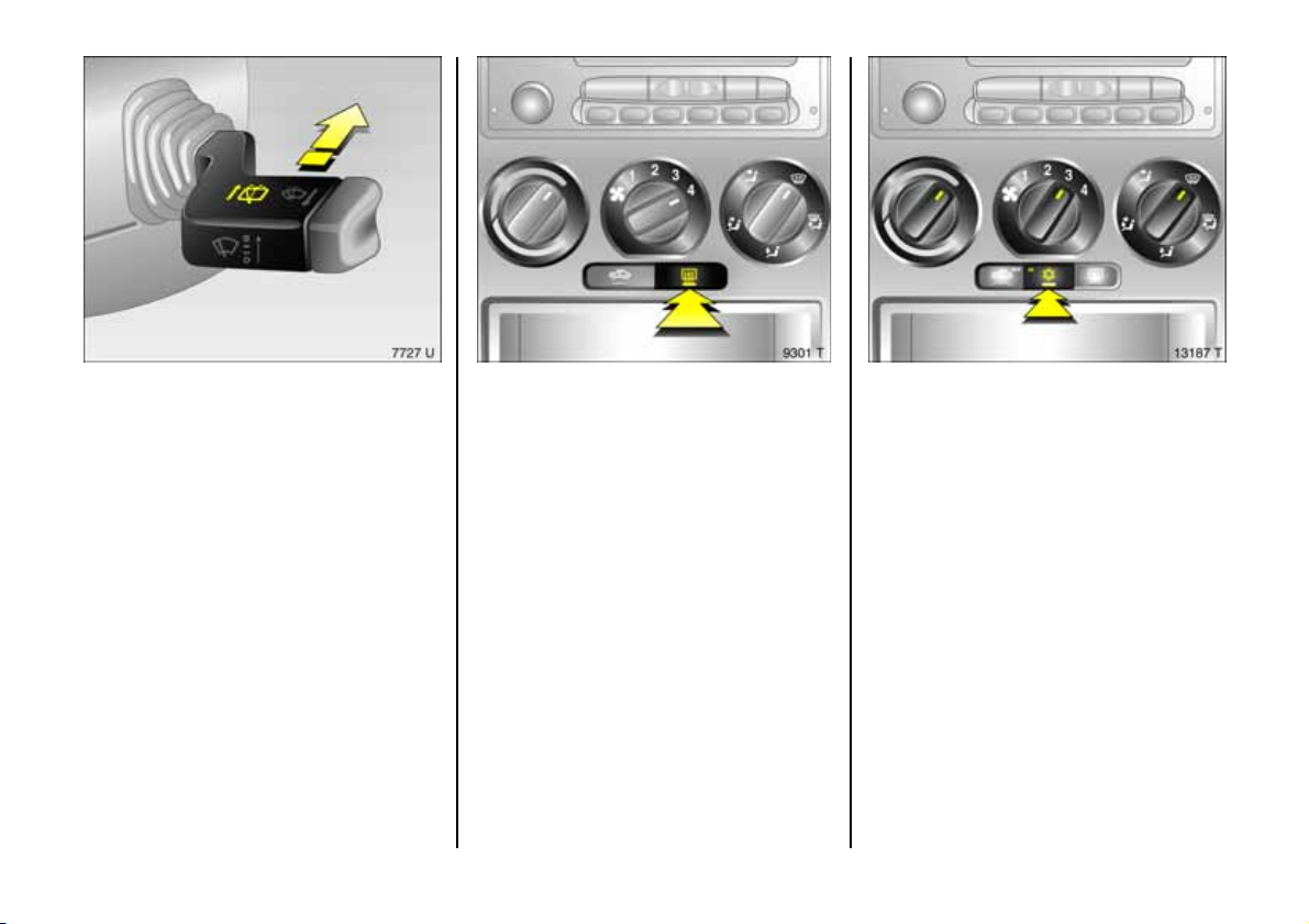
Operating rear window wiper and
wash systems 3:
Wiper on = Push lever forward
Wiper off = Pu ll le ver to ward s
steering wheel
Wash = Push leve r f orward
and hold
The rear window wiper wipe s in timed
interval mode. Continuous wiping takes
place during washing.
6 Further information, see pages 236, 242.
He ated rea r win dow,
heated ex terior mirrors 3:
On = Press
Ü
Off = Press Ü again
The rear window and e xterior mirror
heating is switched off automatica lly after
approx. 15 minutes.
6 Further information, see
pages 140, 146, 151.
To dry fogged or icy
windows:
Turn rotary switch for
heate r and blower clockwise,
air distribution to
V
Press air conditioning switch n 3
Close centre air vents; open sid e air vents
and direct them towa rd s the door windows.
6 Heating, ventilation, see page 136,
air conditioning system 3 , see page 141,
electron ic air conditioning system 3, see
pag e 148.
17
Page 20
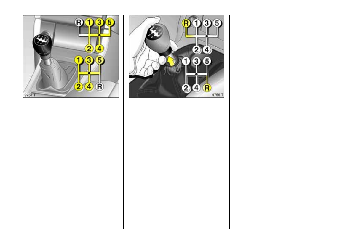
Manual transmi ssion:
o =Neutral
1 to 5 = 1st to 5th gear
When shifting up from 4th to 5th gear:
push the lever towards the right at the
beginning of the shift opera tion.
When shifting from 5th to 4th gear:
do not e xert any force towards the left.
18
Manual transmiss ion:
R = Re verse gear
Reverse gear: With vehicle stationary, pull
the ring up three seconds after de-
clutchin g and engage gear.
If the gear does not engage: with lever in
neutral, release clutch pedal an d depress
again, then re pea t gear selection.
Page 21
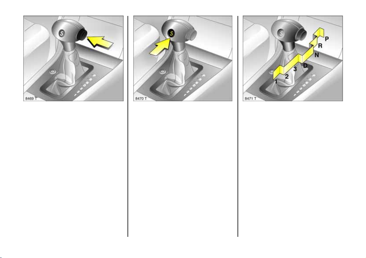
Automatic transmission 3:
P = Park
(wit h s ele ctor le ver lo ck)
R = Reverse
N = Neutral
Engine may be started on ly in P or N . To
move out of P switch on ignition, press foot
brake and p ress b utton on selec tor lever.
To engage P or R, push button on selector
lever.
P: Only with vehicle stationary, first
apply hand brake
R: O nly with vehicle stationary
6 Further inform ation, see page 155.
D = 1s t to 4t h ge ar
3 = 1st to 3rd gear
2 = 1st and 2nd gear
1 = 1st gear
Plus:
S = Sporty driving programme
Selec t 3 , 2 or 1 if certain gears are not
desired, e.g. 4-3-4 . . . on winding road s, or
in orde r to utilize the engine brak ing effect
when driving downhill.
Press button on selector lever to
engage 3 or 1 .
6 Further information, see page 15 6.
Lock to preven t
ina d vert en t sele ctio n of
position P, R, 3 or 1:
Press button on selector lever.
Do not press b utton when shifting into a ny
position in the direction 1 to N or R to D.
6 Further information, see page 155.
19
Page 22
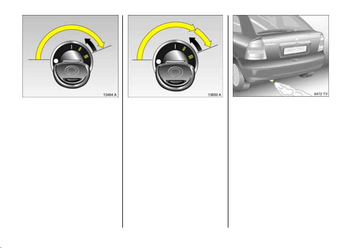
Sta r ting , petr ol en g in es:
Manual transmi ssion: in neu tr al
with clutch depressed,
Automatic transmission: in P or N,
D o n ot a c celer a te
Tu rn key to po sit ion III
The initially increased engine speed
automatically falls as the engine
tem perature r ise s.
Before repeatin g the starting procedure,
turn the key ba ck to o in the starter switch,
remove it and then reinsert it. Then repeat
the starting procedure.
6 Electronic imm ob ilizer, see pag e 5 1,
further information, see
pages 160, 161, 193.
20
Starting, di esel en gines:
Manual transmiss ion: in neutral
with clutch depressed,
Automatic transmission: in P or N,
Do not accelerate,
Turn key to position II;
When the preh eating control
indi cat or go es o ut
tu rn key t o III
Before repea ting the startin g proc edure,
turn the key back to o in the starter switch,
remove it and then re insert it. Then repeat
the starting procedure.
6 Electronic immobilizer, see page 51,
further information, see
pages 160, 161, 193.
1) Preheating s yste m switch es on only if outs id e temperature i s
low.
1)
,
Exhaust gases are poisonous
Exhaust gases contain carbon monoxide,
which is extremely poisonous but is
odourless and colourless.
Therefore never inhale exhaust gases, and
never run the engine in an enclosed space.
You should also avoid driving w ith the
tailgate open, as exhaust gas es could
enter the passenger compartment.
6 Exhaust gases, see pag e 1 69.
Page 23
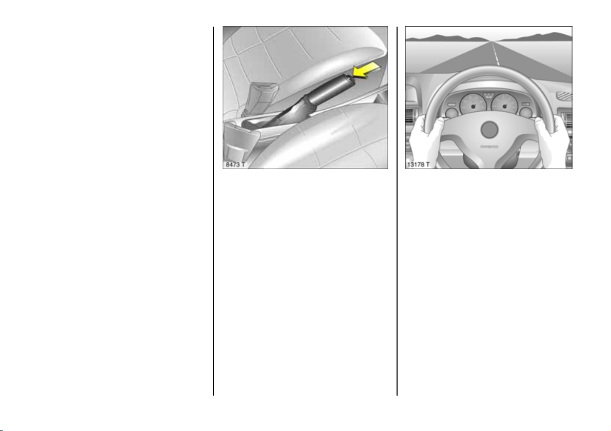
Before starting off, check:
z For tyre pressure and condition, see
pages 183, 268,
z Engine oil level and fluid levels in engine
com partment, see pages 229 to 236,
z All windows, mirrors, exterior lighting
and num ber p la tes ar e fre e from dirt,
snow and ice and op erational,
z Do not place any objects in front of the
rear window, on the instrument panel or
in the area in which the airbag s inflate,
z Seats, seat belts and mirrors are
corre ctly ad justed,
z Bra ke op erat ion.
Releasing the hand brake:
Raise lever slightly,
Press l oc k bu tton,
Lower lever fully
6 Brakes, see page 179.
And no w , h ave a go od jo ur ney!
Drive carefully,
economically and
with t he envi ronme nt in m ind
While driving, do not do anything that
could dis tract you.
Take heed of the traffic reports given out
on the radio.
6 Driving hints, see page 160,
saving fuel, see page 162,
environmental protection, see page 16 4.
21
Page 24
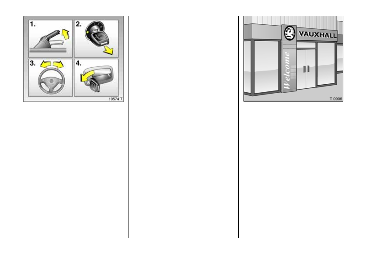
Par king the vehicle :
Apply handbrake firmly,
en g ine off,
re move key,
loc k st eer in g whe el,
loc k doo rs
6 Further inform ation, see pages 51, 160,
radio remote control 3, see page 52,
central lock ing system 3, see page 54,
Vauxhall alarm system 3, se e p age 59.
Advi ce whe n pa r king :
z Always ap ply hand brake firmly. On
slopes apply the hand brake as firmly as
possible.
z W ith manual transmiss ion, engage first
gear or re verse gear and with automatic
transmission 3, place selector lever in
position P.
z C lose windows, sun roof 3 and
convertible folding top 3.
z Re move the ignition key , otherwise a
warning signal will sound when the
driver’s door is opened.
z In v ehicles with automatic
transmission 3 the key can only b e
removed in selector le ver position P.
z Turn steering whe el until lock is felt to
engage (anti-theft protection).
z Sw itch off exte rior lights, otherwise the
headlamp wa rning device 3 w ill sound
when the driver’s door is opened.
z Engine cooling fan may run on after the
engine has been switched off.
Service work,
Maintenance
We recommend that you entrust all work to
your Vauxhall Approved Repairer, who can
provide you with reliable service and
correctly perform all work according to
factory instructions.
6 If You have a p roblem, see page 226,
Service interval d isplay, see page 30.
22
Page 25

Genu ine V auxh a ll Parts an d
Accessories
We recommend that you use "Genuine
Vauxhall Parts a nd Accessories" and
conversion parts released expressly for
your vehicle type. These parts have
undergone special tests to establish their
reliability , safety and specific suitability for
Vauxhall vehicles. Despite continuous
market monitoring, we cannot assess or
guarantee these attributes for other
produ cts, ev en if t h ey have bee n gran ted
approva l by the relevant authorities or in
som e other form.
"Genuine Vauxhall Pa rts and Accessories"
and conversion parts approved by
Vauxhall can be obtained from your
Vauxhall Approved Repairer, of course.
Here you will be given com prehensive
advic e about pe rmitted technical changes
and correct installation will take place .
For your safety
Carry out regularly the checks
recom mende d in the individual sections
of this Owner's Manual.
Ensu re th at y our v ehicle is se rv iced as
specified in the Service Booklet. We
rec ommend that you consult your
Vauxhall Approved Re pairer.
Have faults remedied without delay!
Consult a workshop. We recommend
your Vauxhall Approved Repairer. If
necessary, interrupt your journey.
6 Maintenance, se e pages 2 28 to 238
That was a brief overview.
Please read on!
Your vehicle has still more
Instruments
and controls,
po ssibl y also optional
equ ipment. 6
You will also find further
important information on
operation,
saf ety and
maintenance
and a complete
index.
6
6
23
Page 26
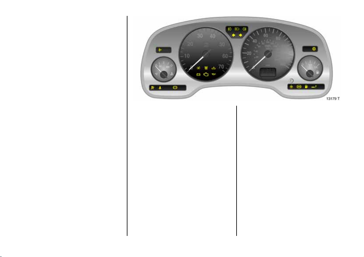
Instruments
24
Control indicators
The control indicators described here are
not p resent in all vehicles. The description
applies to all ins trument versions.
?
Fault in autom atic
headlamp range adj ustment 3
Control indicator lights up for a few
seconds w hen ign ition is switched on. If it
lig hts up wh en driving, a fa ult has
occurred. Consult a workshop immediately.
We recom mend your Vauxhall App rov ed
Repairer. Headlamp range adjustme nt,
see page 115.
v
Air b ag s y ste m s 3 ,
Belt t ens ion ers
see page s 76, 86.
X
Seat belt 3
Control indicator lights up (accompanied
by an acou stic warning): Fasten you r seat
belt.
Page 27
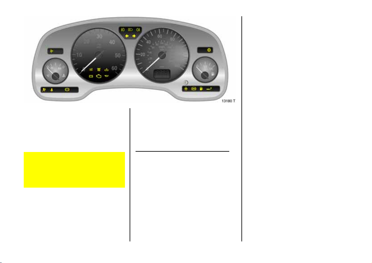
!
Preheating 3 for diesel engines
Control indicator lights up during
preheating.
Preheating system switches on only if
outside temperature is low.
R
Bra k e sy s t em ,
clutc h syste m
Control indicator lights up when ignition is
switched on if hand brake is app lied and/or
brake/clutch fluid le vel is too low. Further
information, see pages 180, 234.
If it lights up when the hand brake is not
applied: stop the vehicle; interrupt your
journey immediately. Consult a
workshop. We recommend your
Vauxhall Approve d Repairer.
@
Electronic ally controlle d
engine cool ing 3
Control indica tor lights up when ignition is
switched on. Goes out shortly after engine
sta rts .
If it lights up when the engine is running
A f a ul t has o ccu r r ed in th e en g i ne co ol i n g
system or the cooling circuit of the air
conditioning. Driving m ay be continued.
Check coolant level, see page 233. We
recommend that you consult your Vauxhall
Ap proved Repairer.
25
Page 28
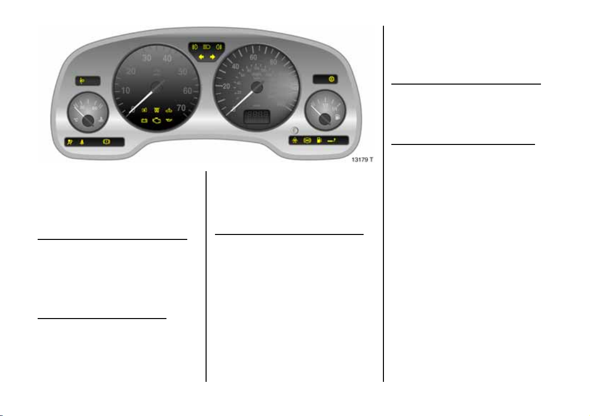
A
Engine electr onics, transmission
electronics,
im mobili zer
Control indicator lights up for a few
seconds when ignition is switched on.
If it lights up when the engine is running
Fault in engine electronics system or
transm ission electronics system. Electronics
switch to limp-home program, fuel
consump tion may increase and driveability
of t h e v ehicle may be i m pai red, see
page 170. We reco mmend that y ou co nsult
your Vauxhall Approved Repairer.
If it flashes when the ignition is on:
Fault in the ele ctronic immobilize r system;
the engine cannot be started , see page 51 .
p
Alternator
Control indica tor lights up when ignition is
switched on. Goes out shortly after engine
sta rts .
If it lights up when the engine is running
Sto p the v ehicle a nd switch o f f the e ng ine.
The batte ry is not being charge d. On
engines Y20DTL, Y20DTH, Y22DTR
engine cooling may be interrupted. We
recommend that you consult your Vauxhall
Ap proved Repairer.
1)
Z
Exhaust emission
Control indicator lights up when ignition is
swi tch ed on. Go es ou t sho rtl y aft e r engin e
starts.
If it lights up when the engine is running
Fault in emission control system. The
permitted emission limits may be
exceeded. Consult a workshop. We
recommend your Vauxhall Approved
Repairer.
If it flashes when the engine is running
For fault that can lead to d estruction of the
catalytic converter, see page 170. C onsult
a workshop imm ediately. We recom mend
that you consult your Vauxhall Approved
Repairer.
26
1)
Sales designation, see pages 24 7, 248, 249.
Page 29
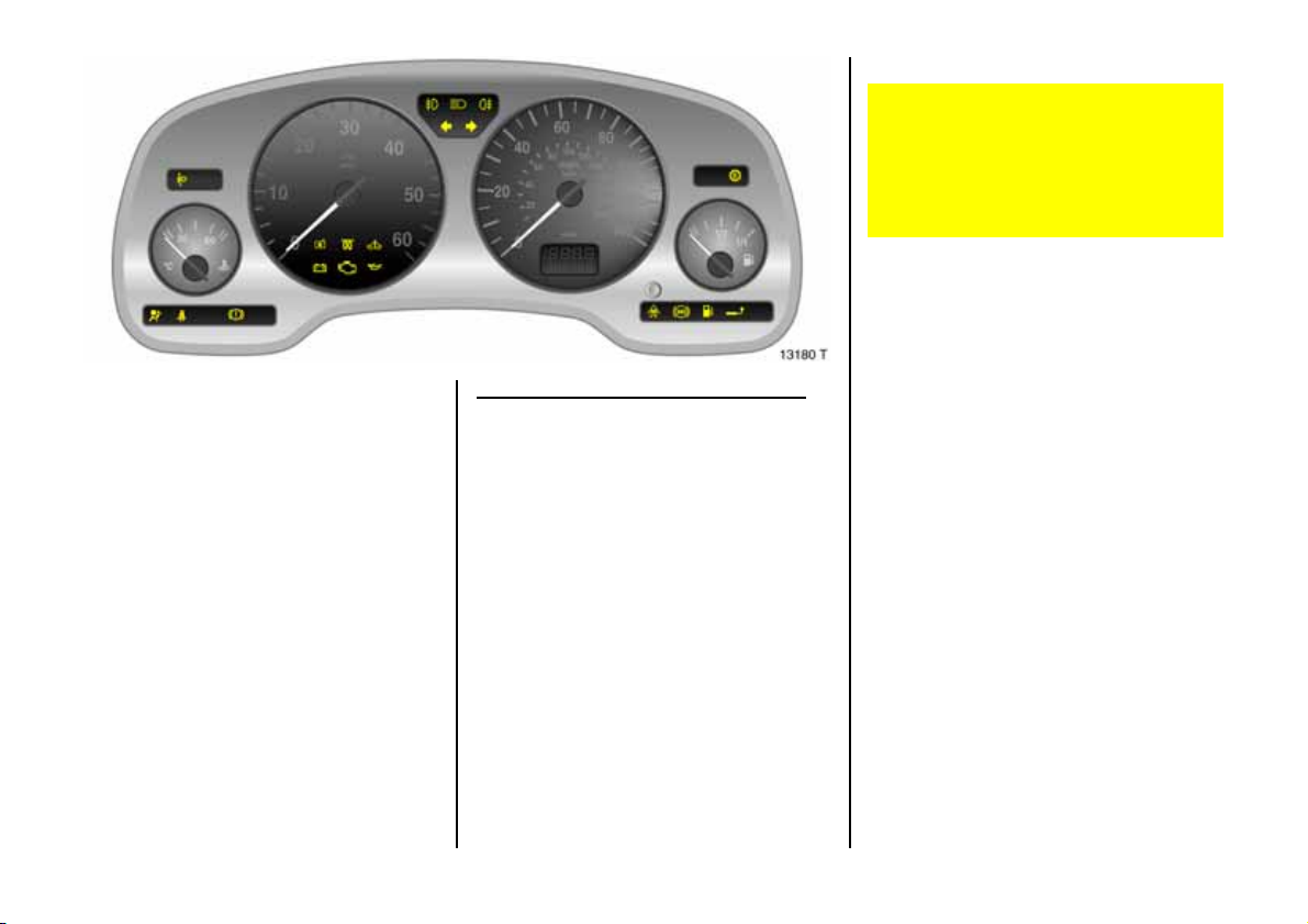
I
Oil pre ssure
Control indicator lights up when ignition is
switched on. Goes out shortly after engine
starts. Can light up intermittently when
idling with hot engine; must go out when
engine speed is increased.
If it lights up when the engine is running
Engine lub rication may be interrupted. This
may result in dam age to the engine and/or
lock ing of the drive whe els:
z Depress clutch.
z Move ge ar s hift lever to neutral, or with
automatic trans mission place selector
lever in N .
z Steer as quickly as pos sible out of the
stream of traffic, without impeding other
vehicles.
z Switching the ignition off (Position I).
When the ignition is off, c onsiderab ly
mo re force is n e eded t o brak e an d ste er .
Do not remove key until vehicle has
come to a s tandstill, otherwise the
steering column lock c ould engage
un ex pe ct edl y .
Consult a workshop. We recommend your
Vauxhall Approved Re pairer.
>
Fog lamps 3
Control indicator lig hts up when fog lamps
are switched on.
P
Main beam
Control indicator lights up when ma in
beam is on and w he n headlamp flash is
operated.
r
Fog tail lamps
Control indicator lights up when fog tail
lamp is switched on.
O
Turn signal lamp s
Control indicator flashes when turn signal
lamp s are on. Ra pid flashes: a turn signal
lamp bulb has failed.
27
Page 30
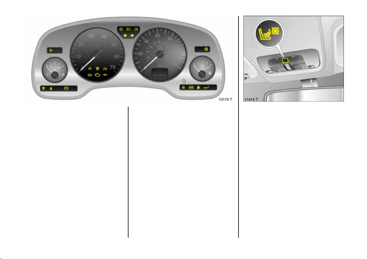
1
Automatic transmission electronically
controll ed drive programm es 3
Control indicator lights up when sporty
driving program me operative.
Further information , see page 156.
v
Tract ion Control system 3,
Electronic St abili ty Progra m 3
see page s 172, 174.
28
u
Anti-lock brake system 3
see page 181.
Y
Fuel leve l 3
Illum inate: Fuel supply low, fuel gauge in
re ser ve ar ea .
Flashing: Fuel tank empty. refuel
immediately, see page 167.
Never let the tank run dry !
Die s el engi n e s: if t h e tan k be comes em pty,
a complicated proce dure is necessary to
bleed the fuel system. We recommend that
you consult your Vauxhall Approved
Repairer. Bleeding diesel fuel system, see
page 19 3.
g
Trai ler turn signal 3
Control indicator flashes in time with turn
signal lam ps when towing. Does not flash if
a turn signal lamp on the towing vehicle or
trailer fa ils .
y
Seat occupancy recogniti on 3,
see page s 81, 86.
Page 31
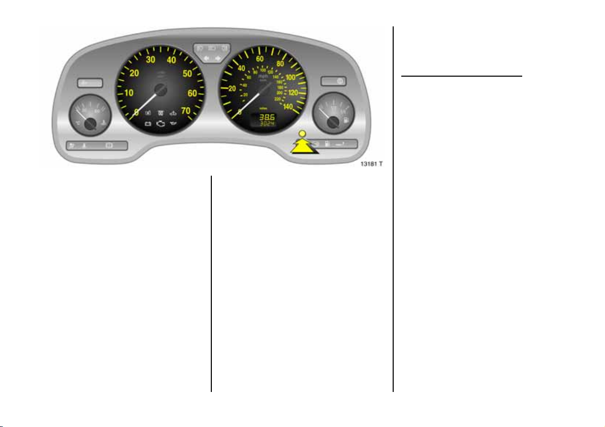
Trip odometer
To return to zero, depress reset knob with
ignition switched on and trip odometer
display activated.
Vehicles with clock in odometer
To set to z ero, hold reset knob down for
approx. 2 seconds with ignition switched
on and trip od om eter activated .
Switc h between trip odometer display and
time display 3 by pressing a nd holding
down the reset knob for approx. 2 seconds
(see next page).
Tachometer
1)
Indicates engine spe ed.
Warn ing zone : M aximum p ermissible
e ngine sp eed ex ceeded ; dan ge r to en gine.
1)
The inst rum ent s in your vehic le may d iffer
from the instruments illustrated here.
Spee dom eter1)
Indicates the vehicle speed.
Odometer
Records the miles/kilometres drive n.
When the ignition is off, the number of
miles driven can be displayed for
approx. 15 seconds by briefly pressing the
setting knob.
29
Page 32
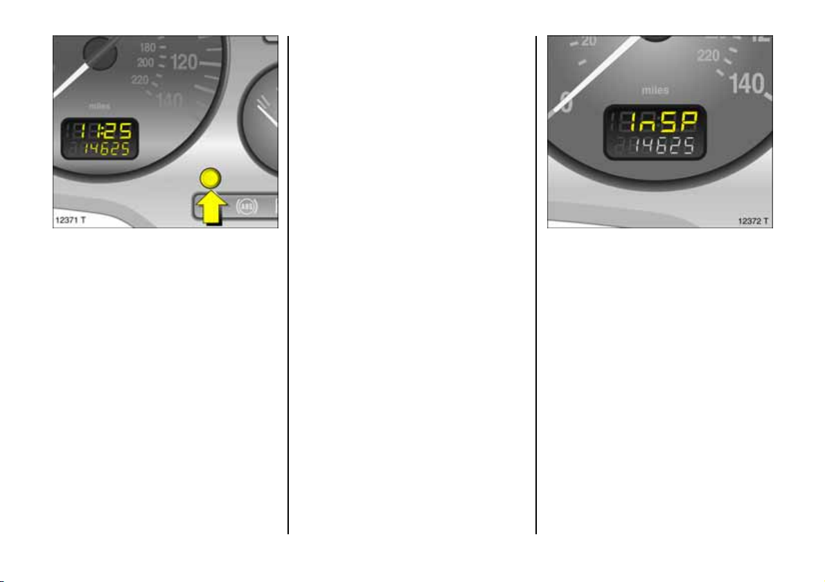
Setting the time
With time displayed, press reset knob in
instrument:
Press for approx . 2 s econds ,
Hours flash,
Pre ss brie fly ,
Set h ours,
Press for approx . 2 s econds ,
Minutes flash,
Pre ss brie fly ,
Set minutes,
Press for approx . 2 s econds ,
Clock starts at 0 seconds.
Ti me di splay in odomet er 3
To switch between trip odometer and time
display 3 give reset knob a s hort press.
W h en the veh icle lights are on, the
brightness of the display can be adjusted
using the right-hand knurled knob k be low
the light switch, see pag e 11 6.
30
Service interval display
If InSP appears in th e trip odom eter display
whe n the ignition is switched on, the ne xt
service interval is due and should be
performed within one week or 300 m iles
(500 km). We recomm end that you consult
your Vauxhall Approved Repairer.
The service inte rval display takes no
account of off-the-roa d periods during
which the battery is d isconnected.
For this reason the maintenance intervals
spec ifie d in the Service Bookle t have
priority, and should be observed,
see page 2 28.
Page 33
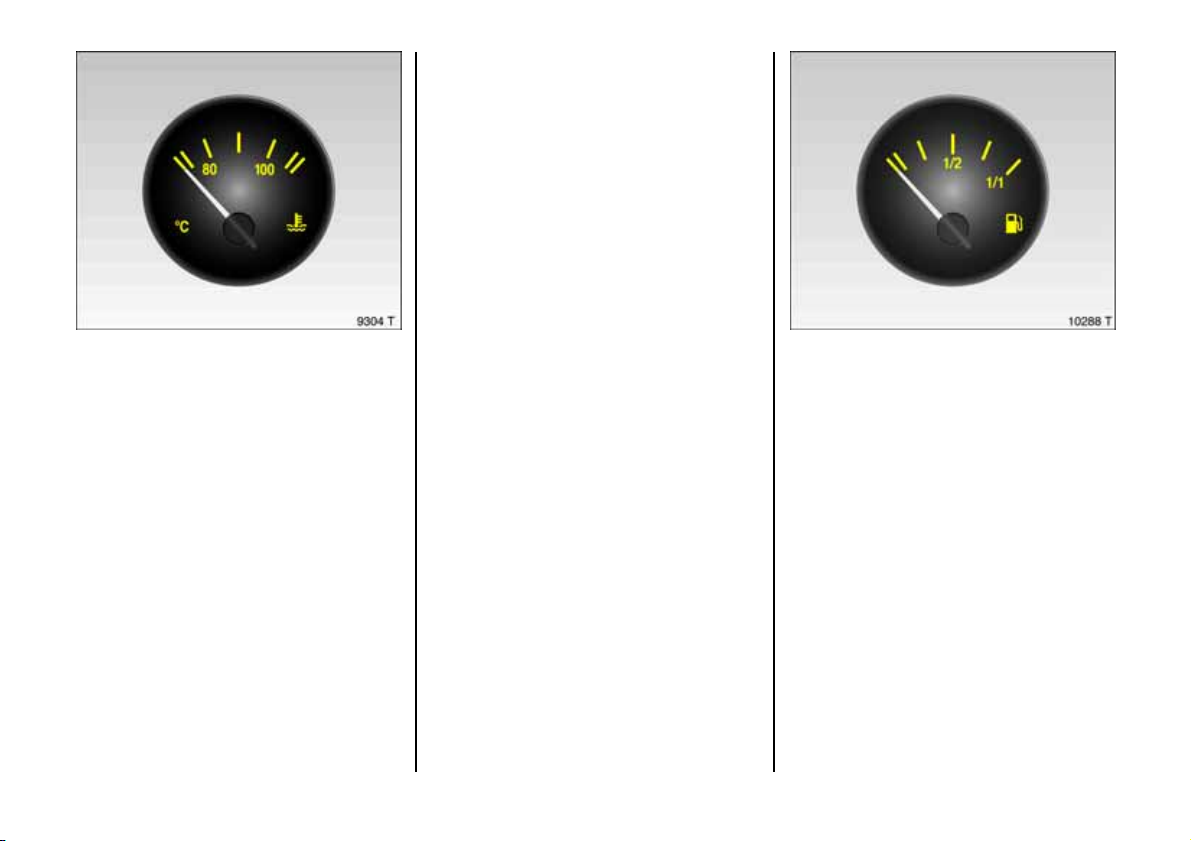
For physical re asons, the engine
temperature gauge shows the coolant
temperature only if the coolant level is
adequate.
Durin g oper ati o n the s ys t em is pr es su ris ed.
The temp erat u re ma y there fo r e rise brief ly
to over 100 °C.
In order to save fuel, coolant temperature
is electronically c ontrolled 3. This may
cause fluctuations in the coolant
temperature display.
Co ol an t te mp era t ur e di sp la y
1)
Pointer in zone
at left = Engine operating
temperature not
yet reache d
Pointer between
the zones = Normal ope rating
temperature
Pointer in red
zone = Temperature too
high :
Stop ve h icle an d
switch off engine.
Danger to engine.
Check co olant level
imme diatel y, see
page 233.
1)
The inst rum ent s in your vehic le may d iffer
from the instruments illustrated here.
Fuel gauge
1)
Pointer in red
warning z one or
= Reserve level.
Y lit
Pointer in red
warning z one or
Y flashing
=Refuel, see
p ag e 16 7.
Never let the tank run dry!
Diesel engines: The fuel system is difficult
to bleed if the tank has b een allowed to run
empty, se e page 19 3.
Because of the fuel remaining in the tank,
the amount of fuel required to fill the tank
may be less than the specifie d tank
cap acity.
31
Page 34
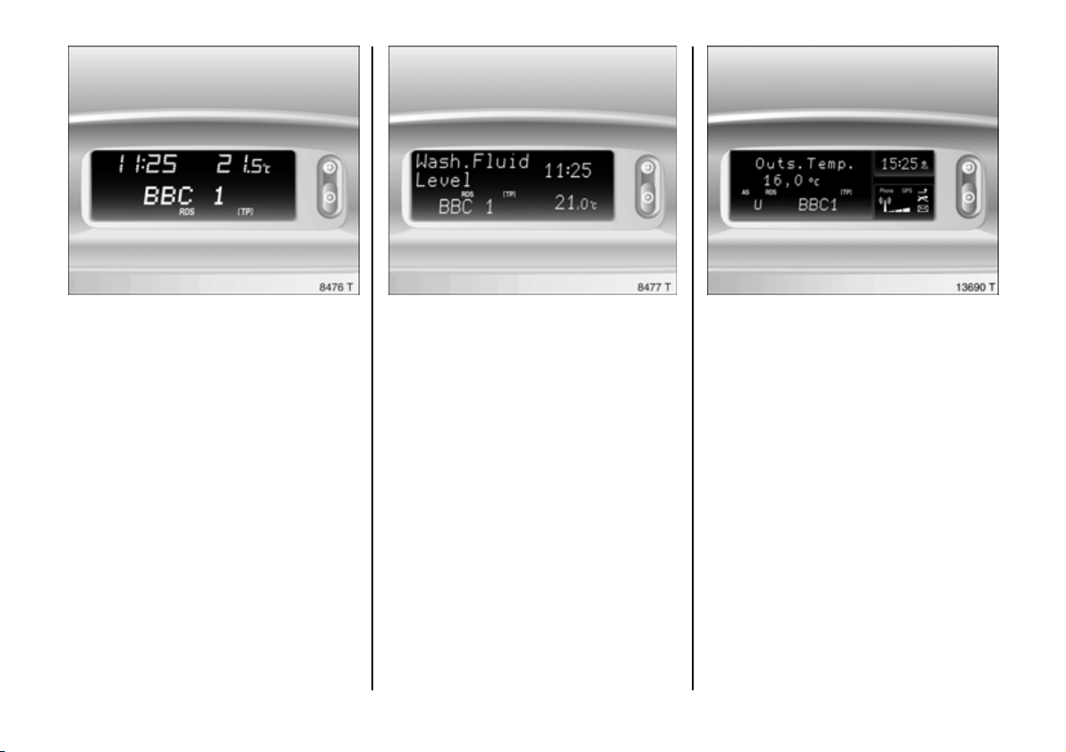
Information display
Tripl e inform ation d isp lay 3
Display of time, outside temperature and
radio/d ate.
The tim e and outside temperature are
displayed when the ignition is on. The date
is displayed when the radio 3 is s witched
off.
When the ignition is off, the time, date and
outside temperature can be made to
appear for approx. 15 se conds by briefly
pressing one of the two buttons adjacent
to the display.
32
Multi-inform ation d isp lay 3
Display of time radio 3 date, ou tside
temperature, check control, trip computer.
The display operates when the ignition is
switched on. Time is continually d isplay ed
while the date is displayed when the radio
is off.
When the ignition is off, the time, date and
outside temperature can be displayed for
15 seconds by briefly pressing one of the
two buttons next to the display or the
button on the wiper stalk.
Mult i-informa tion displa y for ra dio
tele ph on e 3
Display of time radio/date, outside
temperature, te lephone information, check
control 3, a nd trip compu ter 3.
Th e display o pe ra te s when th e ign ition is
switched on. Time is continually displayed
while the date is displayed when the radio
is off.
When the ignition is off, the time, date and
outside temperature can be displayed for
1 5 se con ds b y br i e fly p r e ssi ng on e of t h e
two buttons next to the display or the
button on the wiper stalk 3.
Page 35
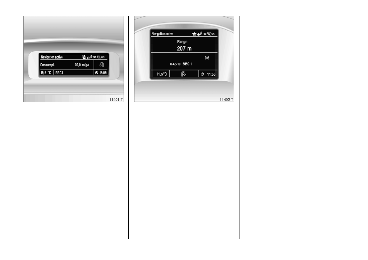
Grap hi cal inform ation d isp lay 3,
Colour information display 3
Display of date, tim e, outs ide temperature
as we ll as information from check
control 3, trip c om puter 3 and
infotainmen t system.
The graphical information display presents
the infor mation in m on ochro me. Th e colour
information dis play presents the
information in colour.
The information displaye d depends on the
vehicle equipm ent and the setting s of the
trip compute 3 and the infotainment
sy ste m.
Interruption of power supply
After a power supply interrup tion or low
battery voltage the electronic radio
disable r 3 and d ate/time must be reset.
See radio operating ins tructions for how to
reset electronic disabler. Setting date and
time, see page 38 .
Upon receipt of a time signal from an RDS
transmitter1), date and time are set
automatically 3, see page 38.
Fault display
--.-°C, F or Safe in the display ind icates a
fault. Have the cause remedied. We
recommend that you consult your Vauxhall
Approve d Re pairer.
1)
RDS = Rad io Data System.
33
Page 36
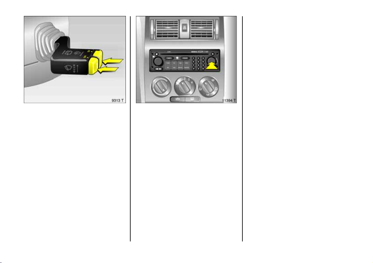
Operation us ing the multifunction button:
Individual menu item s are highlighted by
turning the button and selected by
pressing it. Press the BC button on the
infotainment system to open the trip
computer.
Operating the multi-information
display 3, the graphical information
display
3 or the co lo ur i nform ation
display 3
Th ese funct ion s ar e o p e r ated u s ing t h e
buttons on the wiper stalk or, on vehicles
with infotainment system 3 , by usin g th e
multifunction button.
If check control issue s a warning message,
the display is blocked from other functions.
Acknowledge the message with button
S or R on the wiper stalk 3 or by pr e ss in g
the multifunction button 3. If there are
several fault warnings, acknowledge th em
one at a time.
34
Trip computer functions are operated
using the display menu and the buttons on
the wipe r stalk 3 or the infotainment
sy ste m 3.
Operation using the wiper lever buttons:
Individual functions are selected using
button S. Certain func tion s can be re set by
pressing button R.
Page 37
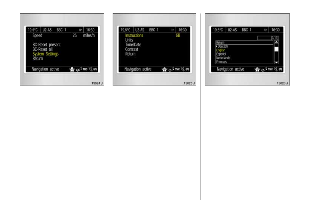
Making system settings for t he
graphi c al info rmatio n disp lay 3 or
the co lour info rm atio n displa y
The figures show execution with the colour
information dis play .
In the trip computer m enu Setti ng s select
System Se tting s.
The system settings m enu will be
displayed.
3
Language selection
You can select the d isplay language for
some f u nc tions .
In the trip computer menu, select item
Ins tructions .
The list of available languages will b e
displayed.
Selec t the re quired language from the list.
Selec tions are indicated by a 6 in front of
the menu item.
35
Page 38
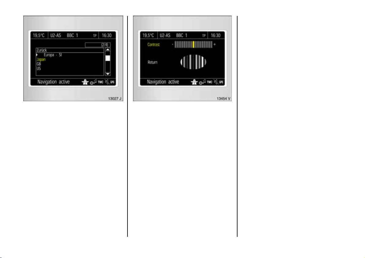
Setti ng units of measure
You can select which units of measure are
to be used.
In the trip computer m enu, select item
Units.
Select from the list of units that opens.
Selections are indicate d by a 6 in front of
th e m enu item .
36
Adjust contrast
In the system settings menu, select item
Contras t.
The contrast m enu will be displayed.
Confirm the required setting.
Page 39
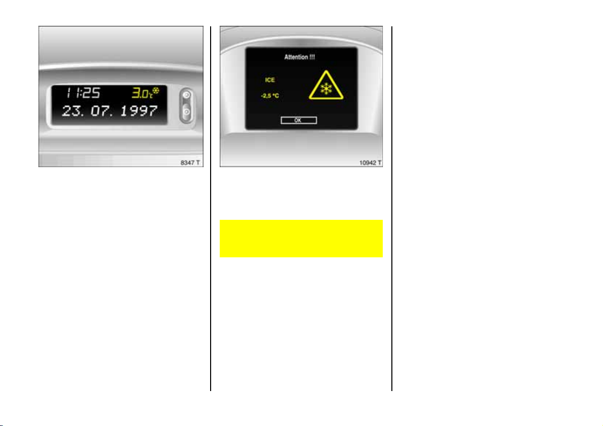
Outside temperature
A fall in temperature is indicated
immediately and a rise in temperature
after a time delay.
The symbol T is show n in the d isplay from
3 °C as a warning for icy road surface s.
On vehicles with graphical information
display 3 or colo ur inf orm at ion display 3, a
message is shown in the dis play as a
warning for icy road surfaces.
Caution: The road surface ma y already
be icy e ven thoug h the display indicates
a few degrees above 0 °C.
37
Page 40
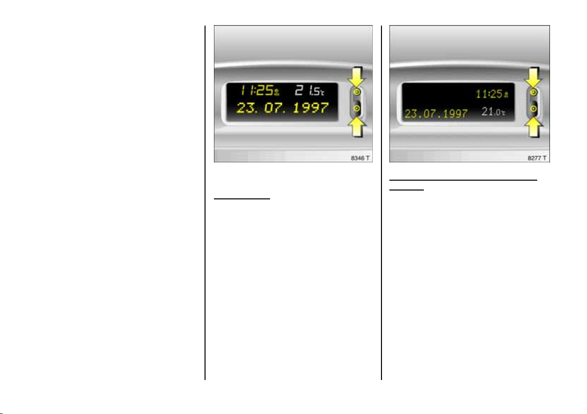
Setting date and time
In the infotainment system 3, time a nd
date are set autom atically upon receipt of
GPS satellite signals1). If the tim e displayed
does not correspond to the local time, it
can be set m anually in 30 minute steps or
be co rrected automa tic ally v ia an RD S tim e
signa l2).
For the radio, tim e an d date can be set
manu ally o r correcte d a ut oma tica lly v ia an
RDS tim e signal 3.
The automatic setting is indicated by Ö in
the display.
1)
GPS = Global Positioning System,
Satellite system for wor ld-w ide p ositioni ng .
2)
RDS = Radio Data System.
38
Vehicles with trip le informa tion display or
multi-i nformati on d isplay 3
Manual setting
Switch off radio. Press Ö and ; above the
display as follows:
Pre ss Ö for approx. 2 seconds:
Day flashes,
;:Set day,
Ö:Month flashes,
;:Set month,
Ö:Year flashes,
;:Set year,
Ö:Hours flash,
;:Set hours,
Ö: Minutes flash,
;:Set minutes,
Ö: Clock is started.
Deactivating and a ctivating automatic
setting 3
Ö hold down for app rox. 2 sec., clock
display is now in setting m ode,
Ö Press twice (until year flashes),
Ö Press an d hold down for app rox .
3 seconds until } flas he s i n displ a y
and te xt "RDS TIME " ap pears (years
flash during this time),
; Press; Display indicates:
RDS TIME 0 = Deactivated,
RDS TIME 1 = Activated,
Ö Press three times.
Page 41
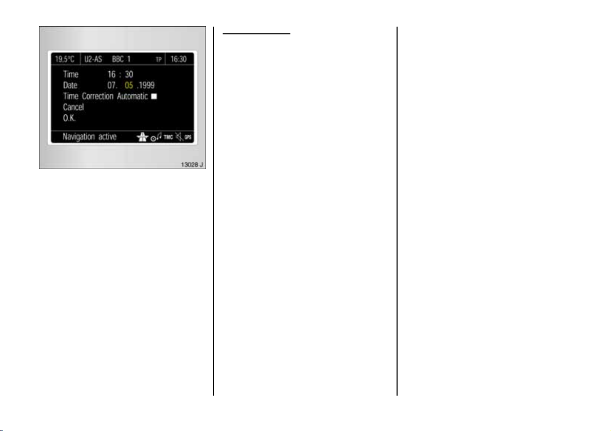
Vehicles with graphical informati on
displ ay 3 or colou r informa tion displ ay 3
In the trip computer m enu Setti ng s select
item System Settings and then item
Time/Date.
The m enu for time/date will be dis played.
Select the menu items required.
Make the desired se ttings and confirm.
Select menu item OK.
Correcting time 3
To correct the tim e, use RDS in the Time/
Date menu to s elec t item Auto. Time
Correction.
The field behind Auto. Time C orrec tion will
be ticked.
39
Page 42
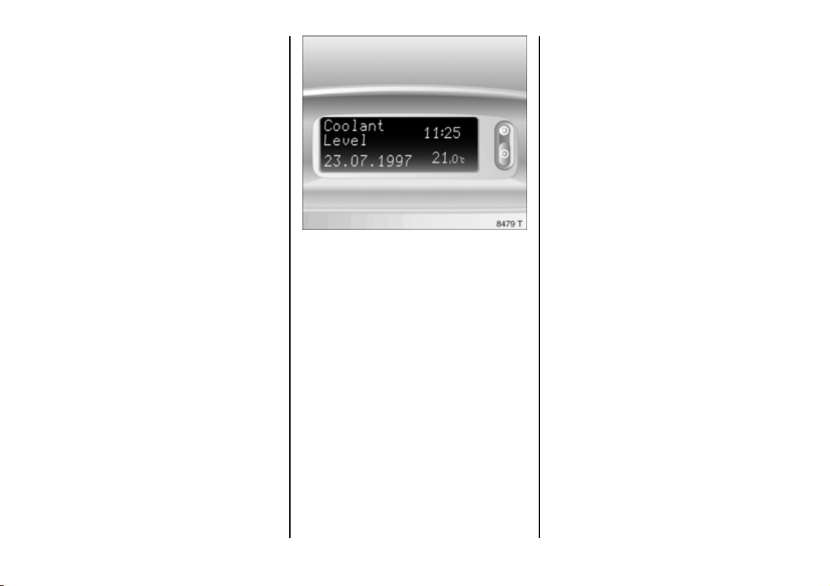
Check control
Check control monitors fluid levels, the
thickness of th e f ront dis k brake linin gs an d
the s tatus of important exterior lighting
components, including wires and fuses.
The lamp monitoring function only
indicates a fa ult if the relevant powe r
circuit is switched on.
Once the ignition has been switched on, all
check control functions are automatically
verified.
The warning
Brake L ight
Che ck
appears on the display. It goes out after
the brake pedal has been depressed once.
Fault warnings app ear on the displa y. If
there are several fault warnings, they are
displayed one after th e other.
Some of the fault warnings appe ar on the
display in a n abbreviated form.
acknowle dge fa ult d isplays as described
on page 34.
Check control warnings have priority.
Brake Pad
Front disc b rake pad worn down to
minimum thickness. H ave the brak e pa ds
replaced. We recomm end that you consult
your Vauxhall Approved Repairer.
Brake Lamp
Fuse
Fuse defective. A n ew fuse should only be
installed after the cause of the troub le has
been rectified. Fuses , see page 208.
Brake L ight
Brake light failure.
Fau l t war n i n g s :
Che ck Oil
Level
Engine oil leve l too low. Check oil le vel
immediately and top u p oil , see page 230.
Coolant
Level
Coolant level in expansion tank too low.
Top up coolant, see page 2 33. H ave the
cause of the fault remedied. We
recommend that you consult your Vauxhall
Ap proved Repairer.
40
Page 43

Fault warnings (ctd.):
Hea d Light
Tail L igh t
Dipped head lamp or tail lam p failure.
Wa sh. F luid
Le vel
Fluid level in windscreen wash system too
low. Top up wash fluid , s ee page 236.
Ac knowledge the fault wa rning as
indica ted on pa ge 34. After
acknowledgement, the wa rning will be
clear e d fro m the display .
Th e fau l t wa r n ing s
Brake Lig ht
Fuse
and
Brake Lig ht
and
Head Light
Tail Light
reappe ar 15 minutes after -they have been
acknowledged.
After the ignition has been switched off
and switc hed on again, the stored fault
warnings app ear on the displa y one after
the other.
Once the faults ha ve bee n remedied, the
fa ult warnings are automatically erased.
Interruption of power supply
Check control automatically checks all
functions after the battery has been
reconnected or charged. Stored fault
warnings appe ar on the display one after
the othe r.
41
Page 44
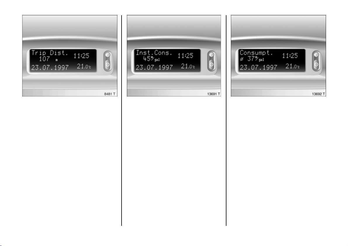
Trip comp ut er 3
Th e trip compu ter s h ow s vehicle data
which it continually records and e valuates
electronically.
Some of the functions appear on the
display in a n abbreviated form.
The figures show the version with multiinformation dis play .
Functions:
z Current consumption,
z Av erage consumption,
z Effective consumption,
z Average s p ee d ,
z Dis ta n ce,
z Rang e,
z Stop watch (multi-information display
on ly) ,
z Outside temperature (only on vehicles
with radio telephone 3).
42
Instantaneous consumption
Display in gal/h below 8mph
(13 km/h).
Display in mpg above 8mph
(d isplay in l/100 km) (13 km/h).
Average consum ption
Calculation of average consumption can
be re-started at any time, see p age 34.
Page 45
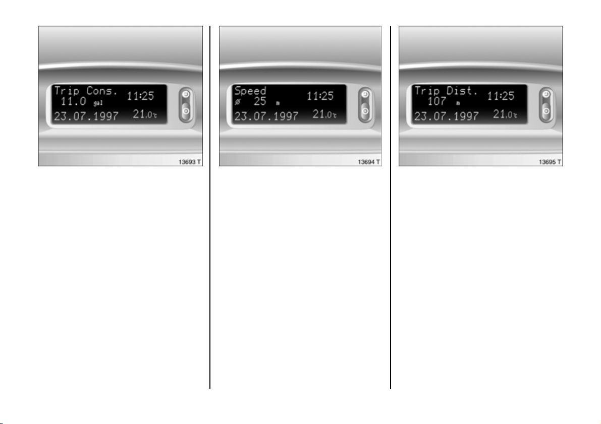
Effective consumption
Shows the a mo unt of f u el consu m ed . Th e
measurement can be re-started at any
time, see page 34.
Average speed
Calculation of average spe ed can be restarted at any time, see page 34.
Stoppages in the journey with the ign ition
off are not included in the calculations.
Distanc e travelled
Shows the numb er of miles (km) travelle d.
Th e meas ure ment can be r e-sta rted at any
time, see page 34 .
43
Page 46
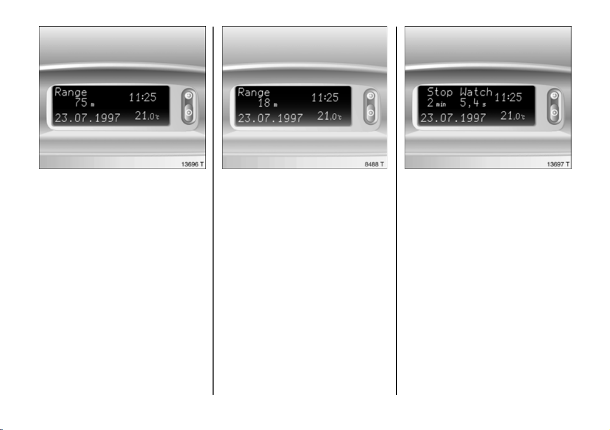
Range over 30 miles (50 km)
Th e ran ge is calc u lated from th e curr en t
contents of the fuel tank and the average
consumption over the last 12 to 20 m iles
(20 to 30 km) of the journey.
After filling up the vehicle, the ra nge
adjusts its elf automatically after a short
time. Manual adjustment is also possible ,
see page 3 4.
44
Range below 3 0 mile s (50 km )
If the fuel in the tank will allow les s than
30 miles (50 km) of trav el, the warning
"Range" appears in the display.
St op wa tch 3
Calculating travel time: The stop watch is
switched off whe n the ignition is switched
off and continues running once the engine
is switched on aga in. The stop watch can
be re-started at any time, see p age 34.
Page 47
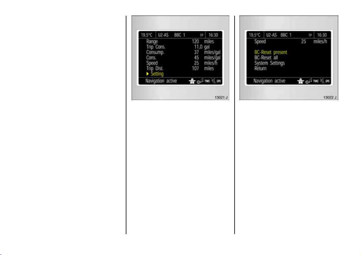
Resetting current trip computer
informa tion
The following trip compute r information
can be re se t (res tart m ea surem ents):
z Range (only with vehicle stationary),
z Effective consumption,
z Av erage consumption,
z Average s p ee d ,
z Dis ta n ce,
z Stop watch (multi-information display
on ly) .
Vehicles with multi-information dis play :
Press button R , s ee page 34.
Vehicles with graphical inform ation
display 3 or colour inform ation display 3:
Select the desired item from the trip
computer menu.
The n select menu item Setti ngs.
The Settings menu of the trip computer w ill
be displayed.
Select BC Reset present in the Se ttings
menu.
The value for the selected function will be
reset and recalcula ted.
The range values can only be reset if the
vehicle is stationary.
After resetting , "- - -" is displayed with the
trip comp ute r informa tion selected. The
recalculated values are displayed after a
brief delay.
45
Page 48
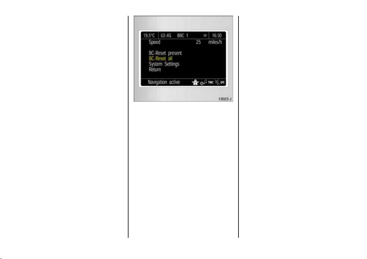
Reset ting mul tiple inform ation
on the trip comput er
The following trip compute r information
ca n b e re set si m ult an e ous l y (va lue s se t t o
zero):
z Effective consumption,
z Av erage consumption,
z Average s p ee d ,
z Dis ta n ce,
z Stop watch (multi-information display
on ly) .
Vehicles with multi-information dis play :
Press button R at lea st 2 seconds.
Interruption of power supply
If the power supply has been interrupted or
if the battery voltage has dropped too low,
the values stored in the trip computer w ill
be lost.
Vehicles with graphical inform ation
display 3 or colour inform ation display 3:
In the S ettings menu, select item
BC Reset all.
The v alues are reset a nd "* **" is d isplay ed.
New values are only displayed when the
engine is running. The average speed is
calculated shortly after starting to drive.
46
Page 49
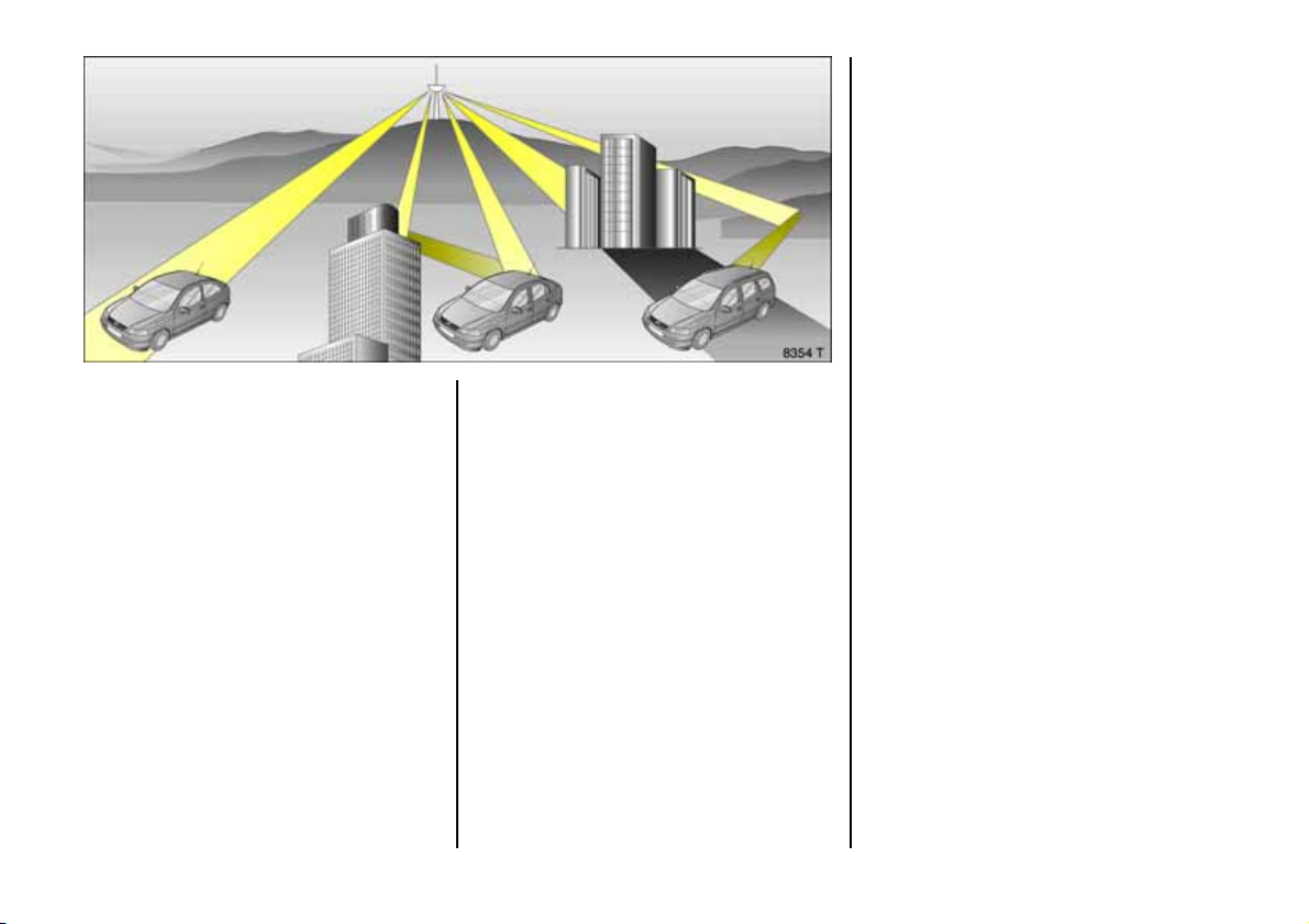
Infotainment system 3
The infotainment system is operated as
desc ribed in the operating ins tructions
supplied.
Radio 3
The rad io is operated as described in th e
opera ting instructions supp lied.
The d isplay for the radio ap pears on the
information dis play .
Car radio reception diffe rs from domestic
radio reception:
As the vehicle aerial is relatively near the
ground , the broadcas ting com panies
cannot guarantee the same quality of
reception as is obtained with a domestic
radio using an overhe ad aerial.
z C hanges in distance from the
transmitter,
z multi-path reception due to reflection
and
z shadowing
may cause hissing, noise, distortion or loss
of reception altogether.
47
Page 50
For further information, see the re spective
operating ins tructions.
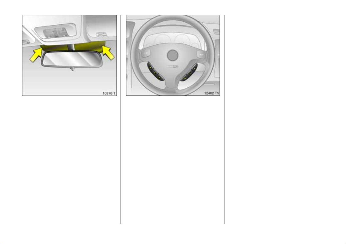
Ele ctro nic data acq uis itio n in to ll
systems
On vehicles with heat-reflecting windscreens 3, mount the chipcard for
electronic data ac quisition and billing in
th e b lack s had ed zone of t h e w indscre en
on the left or the right behind the interior
rear-view m irror, see illustration. If the
chipcard is mounted outside this zone,
malfunctions may occur in data
acquisition.
48
Steering wh eel mounted remote
co ntro l 3
Radio and infotainm ent system functions
can be operated using the buttons on the
steering wheel.
Page 51

Mobile telephones and radio
equ ipment (CB)
The V auxhall installa tion instructions and
the operating gu idelines provid ed by the
telephone manufa cturer m ust be observed
when fitting and operating a m ob ile
telephone. Failure to do so could invalida te
the vehicle’s o perating permit (EU D irective
95/54/EG).
Prerequisites for fault-free operation:
z Professionally installed exterior aerial to
ob tain the max imum range possible,
z Maximum transmission power 10 W,
z Installatio n of the te lephon e in a s uitab le
spot (see note on page 88).
3
Obtain ad vice on predetermined
installation locations for the external
antenna an d equipment holde r and ways
of using devices w ith transmission power of
more than 10 Wa tts. We recommend that
you consult your Vauxhall Approved
Repairer, who will have consoles and
various installation k its and install them in
accordance with regu lations.
Only use the hands-free equipment to
make telephone calls whilst driving. This
can also be a distra ction whe n driving.
Please observe country-specific laws.
When used in the v ehicle interior, mobile
tele phones and radio e quipment (CB)
with integrated ae rial may cause
malfunctions in the vehicle electronics.
Mobile telephones and radio equipm ent
(CB) s hou ld only be used with an ae rial
fitted on the vehicle exterior.
49
Page 52
Keys, doors,
bonnet
Re pl ace men t k e ys
The key is a c onstituent of the electronic
immobilizer. O rd ering keys from a V auxhall
Ap proved Repairer guarantees p roblemfree operation of the electronic
immobilizer. You will av oid unnecessary
costs, difficulties with insurance comp anies
when proce ssing claims and problems
asserting wa rranty claims .
Ke ep th e spar e k ey acces sib le in a safe
place.
Locks, see pa ge 242.
Door lo cking an d u nloc king
From outside:
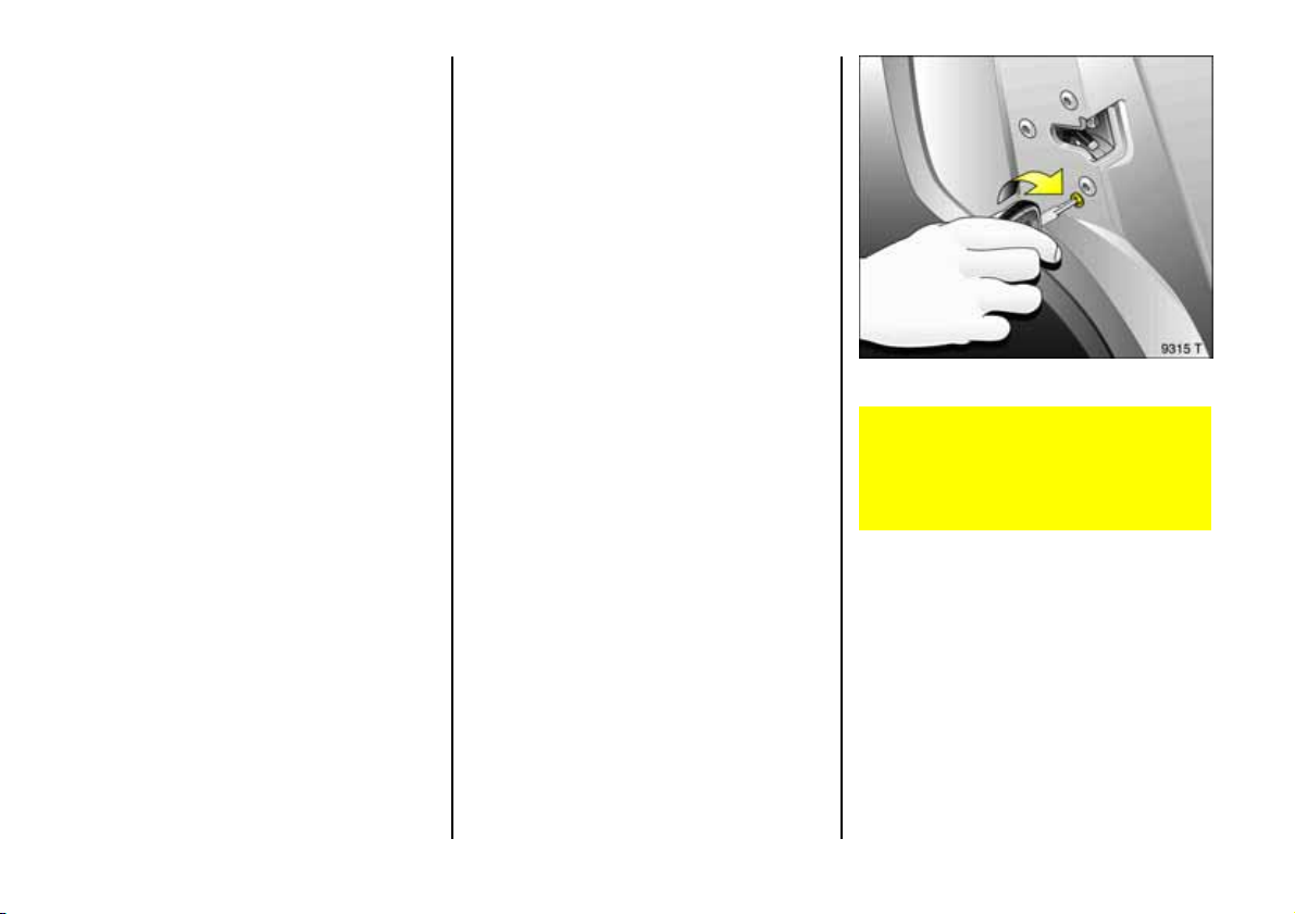
Mechanically, see page 5,
ra di o rem o te co n tro l 3, see page 52 ,
central locking s ystem 3, see page 54 .
Fro m inside
Push down or pull up lock button. To
prevent the driver from being inadvertently
lock ed out, the button on the driver’s door
cannot b e depress ed when the door is
op en .
Child safety locks 3
Use the child safety lock whenever
children are occu pying the rear seats.
Disregard may lea d to injuries or
en dan g e r li fe. Ve hi cl e p ass en ge r s sho u ld
be informed accordingly.
Turn rota ry knob at rear door lock
clockwise from vertical position using key:
door cannot be opened from inside.
50
Page 53
Electronic immobiliser
Th e key pro t ects the v ehicl e from thef t by
means of a n e lectronic engine immobilizer.
Th e sys t em check s w he ther th e vehicle i s
allowed to be started using the key. If the
key has been accepted as "authorised" the
vehicle can be started.
To activate:
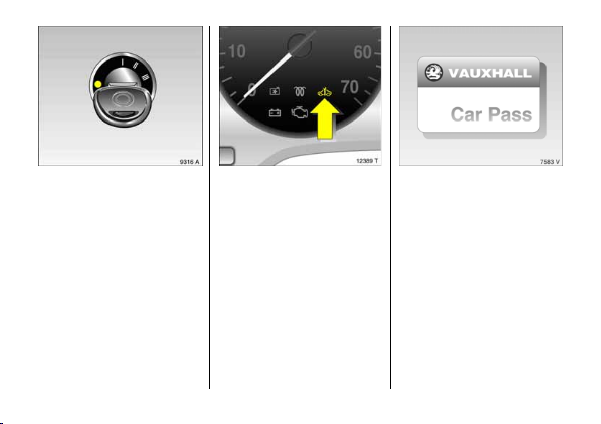
Switch off engine, turn key to position o
and re move .
To deacti vate :
Turn key to position II (ig nition on); the
engine can then b e started.
Deactivation is not possible in any other
way, so keep spare key accessible in a safe
place!
Control i nd icator for imm obilizer A
When the ignition is switched on, the
control indicator A lights up briefly. If the
control indicator flashes when the ignition
is on, th ere is a fault in the immobilizer
sy st e m. T he eng in e can not be s tarted:
1. Turn key to o in ig nition switch and
remove.
2. Re insert key in ignition switch .
3. Then repeat starting proce dure.
If the control indicator A continues to
flash, try to start the engine using the s pare
key and consult a workshop. We
recommend your Vauxhall Approved
Repairer.
If the control indicator A lights up after
th e engi n e has s tarted , ther e is a fau lt in
th e engi n e elec tro n ics or t h e auto mat ic
transmission 3, see pages 158, 170.
Not e
The immobilizer does not lock the doors.
Therefore, always lock vehicle before
leaving unattended and enable Vauxhall
alarm system 3, see page 59.
Th e Car Pas s conta ins al l of t h e vehicle ’s
data and should there fore not be kept in
the vehicle.
Hav e y our Ca r P a s s o n ha n d w h en
consulting a Vauxhall Approved Repairer.
51
Page 54
C entra l locking s ystem,
see page 5 4.
Mechanic al anti -theft locki ng system,
see page 5 6.
Vauxhall alarm system 3,
see page 5 9.
Fully autom atic Conve rti ble foldi ng top 3,
see page 1 30.
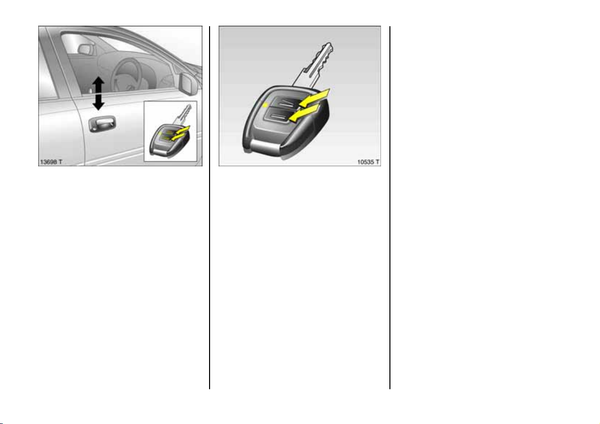
Radio rem ot e c ont ro l 3
The rad io remote control is integrated in
the key.
Us ed to op erate :
z central locking s ystem,
z mechanical anti-theft locking s ystem ,
z Vauxhall alarm system 3,
z fully automa tic Convertible folding
to p 3.
The remote control has a range of approx.
3 metres. The range ma y b e reduced owing
to shadowing and reflection of the radio
wav es. T o ope ra te th e remo te control,
point it at the vehicle.
52
For your convenience, we recommend that
the ce ntral lock ing system alway s be
op erated using the remote control unit.
Handle remote control with care, protect
from moisture and high temperatures and
avoid unnecessary operation.
The light-emitting diode (LED) in the
re mote control unit lights up and the
ha zard w arning lamps flash briefly to show
that the rem ote control is operational.
Page 55
Fault
If the central locking system cannot be
operated with the re mote control, it m ay b e
due to the following:
z The range of the rem ote control has
been exceeded,
z The battery voltage of the remote
control unit is too low. Change the
battery in the remote control unit,
z The remote control ha s been operated
frequently in s uccess ion outs ide the
vehicle's reception range (e.g. at too
great a distance from the vehicle).
Resynchronize the remote control,
z If the ce ntral locking system is
ov erloaded as a re sult of repeated
op eration at short intervals, the power
supply is cut off for approx . 30 seconds,
z Inte rfer en ce from h igh er -po we r radio
waves from other sources.
For central locking system ope ration using
key, see following pages. Have cau se of
fault remedied. We recommend that you
consult your Vauxhall Approved Repairer.
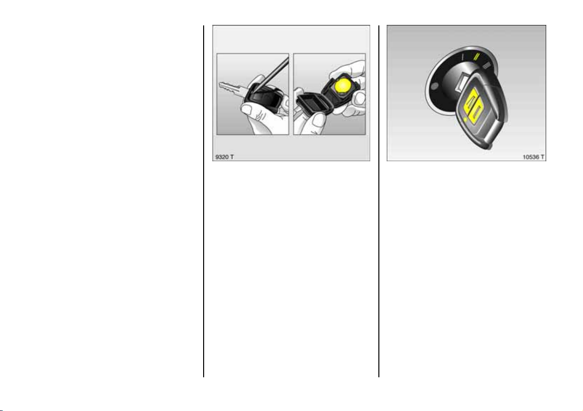
Changing the remote co ntrol ba ttery
Exchange the battery as soon as the range
of the remote control starts to become
redu ced.
Insert a small screwdriver in the notch on
the cover and prise it open. Disengage the
re mote control from the key part and open
the batte ry cover. Replace the battery,
ensuring that it is inserted correctly (see
page 27 8 regard ing battery type). Close
the rem ote control so that it audibly
engages in the key pa rt.
The batte ry change must be performed
within 3 minutes, otherw ise the remote
control will hav e to be re synchronized.
Make sure that you dispose of old batteries
in accordance with environmental
protection regulations.
Synchronizing remote control
In the event of malfunctions, synchronize
remote control:
z Switch on ignition; system will then
remain in synchronizing mode for
30 seconds.
z Briefly press button p or q on the
remote control u nit while th e un it is in the
ignition.
z The central locking system locks and
unlocks to show that the remote control
ha s b ee n sy nch r o n ized .
53
Page 56
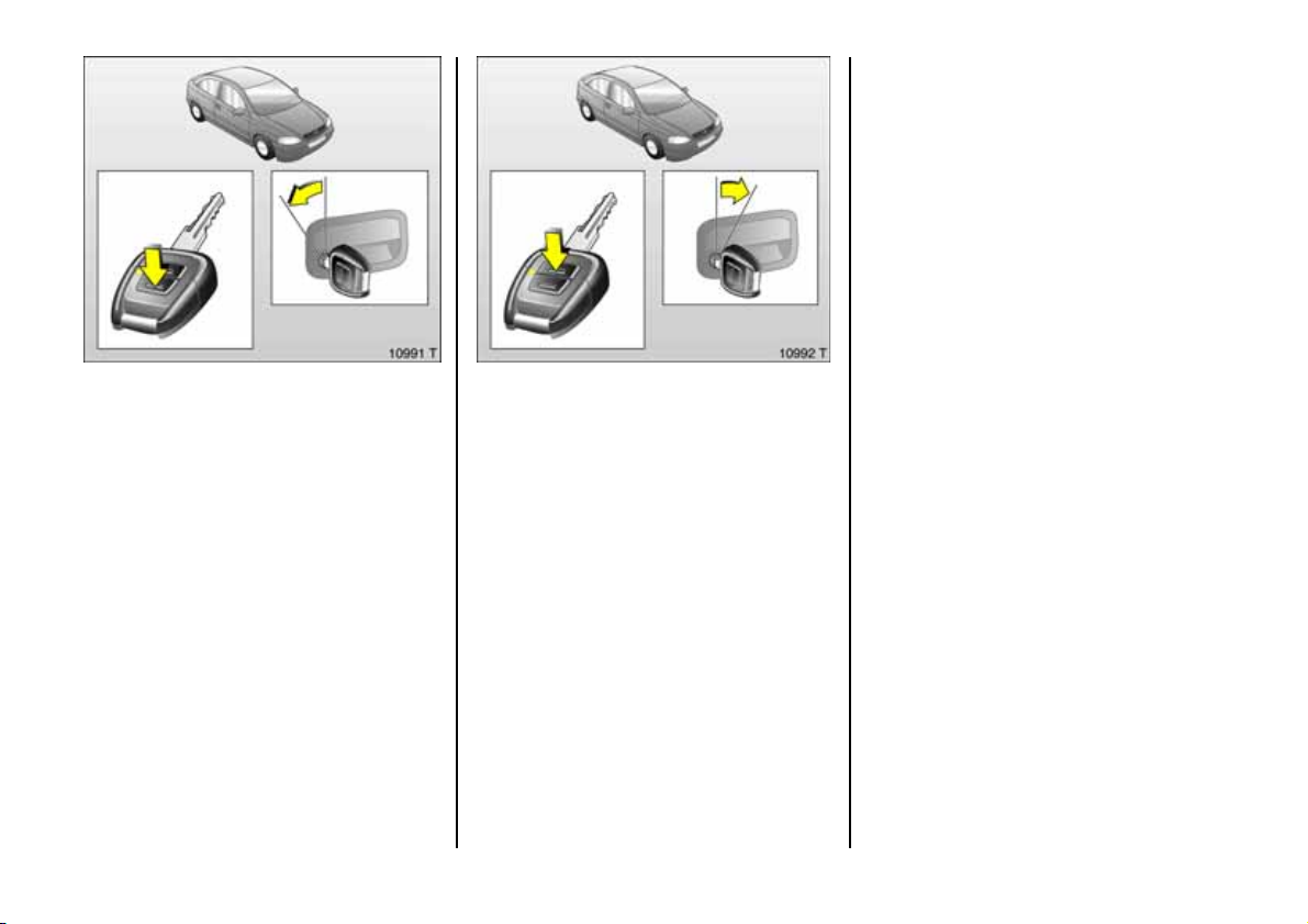
Cen tr al l oc king sy stem 3
For doors, boot lid/tailgate and tank flap.
Locking
Press button p on rem ote control unit
– or –
turn key in driver's door lock toward s rear
of vehicle, then turn it back to the vertical
position and remove; alternativ ely, when
locking from ins ide, press the lock b utton
on one of the front doors with the doors
closed.
To un l oc k:
Press button q on remote control unit
– or –
turn key in driver's door lock towards front
of vehicle, then turn it back to the vertical
position and remove; alternatively, when
unlocking from inside, pull up the lock
button on driver's door.
Not e
z To p reve n t th e dri v er fr o m be ing
ina dvertently locked out, the button on
the driver's door c annot be depressed
wh en the do or is o p e n .
z If the driver's door is not closed properly,
the central locking system will unlock
again immediately after locking.
z To lock the doors from inside (e.g. to
prevent unwanted entry from outside),
push down lock button on driv er’s door.
z Locked doors unlock a utoma tically if an
accident of a certain severity occurs (to
permit ou tside assistance).
Prerequisite: Ignition must not be
switched off.
54
Page 57

Closing windows and sun roof 3
With electric windows 3 and electric sun
roof 3 (e xc ep t Co u pe) th e win dows and
the sun roof can be closed from the
outside: hold key in door locking p osition in
driver’s door lock until all windows and the
sun roof are closed.
Closing w indows and Convertible folding
top 3
With electric windows 3 a nd fully
automatic fold ing top 3 the windows and
the folding top can be clos ed from the
outs ide: hold key in door locking position in
driver’s door lock until all windows and the
folding roof are closed
C ar e mu s t be t aken w he n operating the
electric windows 3 and electric sun
roof 3. There is a ris k of injury,
particularly for children, and a d anger
that articles could b ecome trapped.
V eh icle pas se ng ers should be inf orm ed
accordingly.
Keep a close watch on the windows and
sun roof when closing them. Ensure tha t
nothing become s trapped in them a s
they move.
Overload
If the central locking system is overloaded
as a result of repeated operation at short
intervals, the power supply is cut off for
ap p rox . 3 0 sec o nd s.
Th e syste m is p r o t ec t e d by a f u se in t h e
fuse box, s ee page 208.
55
Page 58
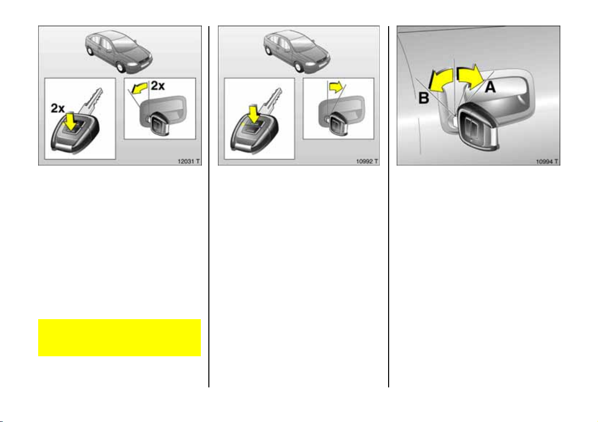
Cen tr al l oc king sy stem,
mech an ical ant i- thef t lo ckin g sy s tem
Locking
All doors must be closed, the driver's door
must have been opened once previously;
press button p on the remote control
again within 10 seconds a fter locking
– or –
turn key in driver's door lock toward s rear
of vehicle aga in within 10 seconds after
locking, then turn it back to the vertical
position and remove.
Lock buttons on all doors are positioned
suc h that doors cannot be opened.
Do not use the sy stem if there are p eople
in the vehicle! The doors cannot be
unlocked from inside.
56
To un l oc k:
Press button q on remote control unit
– or –
turn key in driver's door lock towards front
of vehicle, then turn it back to the vertical
position and remove.
Unlocking is not possible in any other wa y,
so k eep sp are k ey t o ha nd in a s afe p la ce!
Malf un ctio n in cent ral lo cki ng sys tem
A = Unlocking the driver's door
Turn key forward in lock p ast
resistance point as far as it w ill go.
Turn key back to vertical pos ition and
remove.
B = Locking the driver's door
With driver's door closed, turn key
towards rear of vehicle until it will n ot
move any further. Turn k ey back to
vertical position and remove.
The other doors can be opened and closed
by pulling or pushing the interior lock
button (not possible if anti-theft alarm
sys tem enable d be fore ha nd ). Have cau s e
of fault remedied. W e rec ommend that you
consult your Vauxhall Approved Repairer.
Page 59
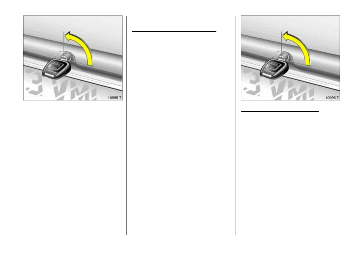
Using th e central loc king sy st em for
tailg ate /b oot lid
Key slot in loc k in horiz ontal p osition
The luggage compartment is locked and
unlocked using the remote control or by
turning the key in the driver’s door lock.
If the key is only turned to the horizontal
after unlocking the ce ntral lock ing system,
the luggage compartm ent re mains locked.
For unlocking, see next page .
Luggage compartment
Locking
Turn key to vertical position.
To unlock
Turn key to horizontal position.
The lock is released by pressing the button.
Key slot in lock in vertical p osition
Luggage compartme nt remain s locked
even if the vehicle is unlock ed using the
remote control or by turning the key in the
driver’s door lock. This position is to be
chos en if the lugga ge c ompartment is to
stay locke d. Turn the key anti-clockwise as
far as it will go.
6
57
Page 60
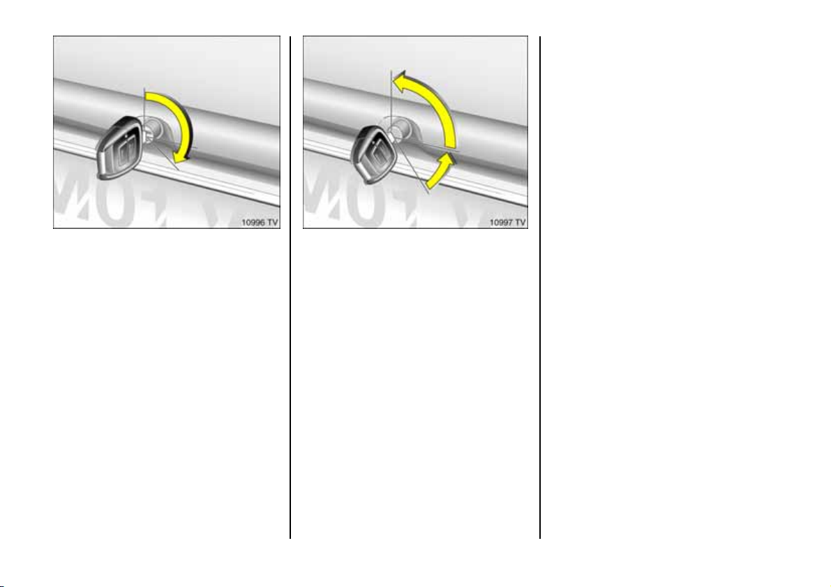
Unlock ing lugg age comp artment w hen
doors are lock ed wit h central loc king
system
Turn key clockwise from vertical or
horizontal position as far as it will go. To
guard ag ainst being locke d ou t, the key
cannot then be removed.
Once the boot lid /tailgate has been closed
and the key turned back to the horizontal
or vertical p osition, the lugga ge
compartme nt is locked ag ain.
In the horizontal position, the luggage
compartment is only unlocked the next
tim e the central lock ing system is unlocked.
Not e
z The central locking system and the anti-
theft locking system for the doors cannot
be lock ed or unlocked from the boot
lid/tailgate lock.
z On the convertible, the boot lid can only
be unlocked if the folding top is fully
open or closed.
z There is a handle or strap on the inside of
the boot lid/ tailgate to aid closing.
z Poisonous exhaust gas can penetrate
the interior if the luggage compartment
is left open. The number plate can only
be prop erly seen and illuminated in
accordance with regulations if the
lug gage compartment is closed. It is
therefore forbidden to drive with the
lug gage compartme nt op en.
z Fitting of accessories on the tailgate/
boot lid will increase its weight. If it
becomes too heavy, it will then not stay
open.
58
Page 61
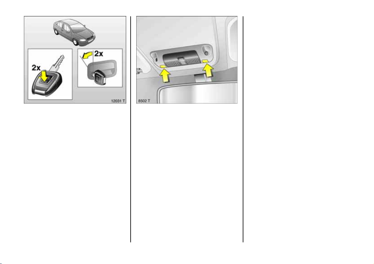
4. Switch on Vauxhall alarm s ystem . LED
lights up. After approx. 10 seconds the
system is activated, without monitoring
of the p ass enger compa rtm ent or v ehicle
tilt. LED flas hes until system is switched
off.
O n the C on v ertibl e, pas se n g er
compartment monitoring is deactivated
when the folding top is open, to prevent
false alarms.
6
Vauxhall alarm syste m 3
monitors
z th e doors, luggage compartment,
bonnet
z th e passenger compartment,
z the vehicle tilt,
z th e i g n it ion .
To activate:
All doors, windows, sun roof 3 and
convertible folding top 3 must be closed.
Press button p on rem ote control unit
again within 10 seconds of locking
– or –
turn key in driver's door lock toward s rear
of vehicle aga in within 10 seconds after
locking, then turn it back to the vertical
position and remove.
Swit ching s yste m o n e x clu ding
monitoring of the passenger
compa rtmen t and the veh icle tilt
e.g. if animals are to be left in the vehicle.
1. C lose boot lid/tailgate and bon net.
2. Press both buttons at the same time to
op e ra te the f ron t re ading l amps whe n
the ig nition is switched off. The LED will
flash for max. 1 0 s econds , s ee next page.
3. Close doors.
59
Page 62
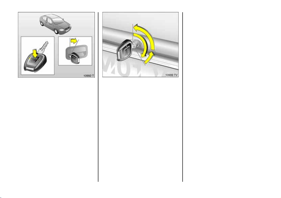
2. Open luggage compartment.
3. Close luggage comp artm ent.
4. To lock: turn the key back to its previous
position. Monitoring of the passenger
compartme nt, luggage compartme nt
and vehicle tilt is activated after
approx. 10 seconds.
To deacti vate
Press button q on rem ote control unit
– or –
turn key in driver's door lock towards front
of vehicle, then turn it back to the vertical
position and remove.
60
Opening a nd closing the lugg age
compa rtme nt w ith Vau x hall a larm sy ste m
activ ate d
1. To un lock : turn key clockwis e as far as it
will go. The luggage compa rtment is
unlocked and monitoring of the
passenger compartment and vehicle tilt
is deactivated .
Page 63
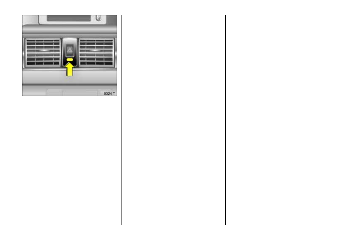
Light e mit ting d iode (LED)
During the first 10 seconds of anti-theft
alarm system activation:
z LED lights up = Test, switch-on
delay,
z LED flashes = Door, tailgate,
bonnet open
or system fault,
After the first 10 seconds of anti-theft
alarm system activation:
z LED flashes = System on,
z LED lights up for
approx . 1 s econd = Switch-off.
If a system fault occurs, consult a
workshop. We recommend your Vauxhall
Ap proved Repairer.
The system’s integrated self-diagnostics
allow s faults to be quickly reme died.
Alarm
Durin g a switch-on phase the ultrasonic
sensors ca n trigg er a maximum of thre e
alarms; legal regulations s tipulate that
other sensors may trigger a m aximu m of
10 alarms.
The alarm take s the form of
z an acoustic signal (horn, 30 seconds)
and
z a visual s ig nal (hazard warning lamps,
5 mi n ut e s)1).
Alarm c an be stopped by pressing
button q (d is able an ti-theft a la rm s ystem)
or pressing button p on remote c ontrol.
1)
Varies from c oun tr y to coun try on account of
nati ona l regu la tion s.
61
Page 64
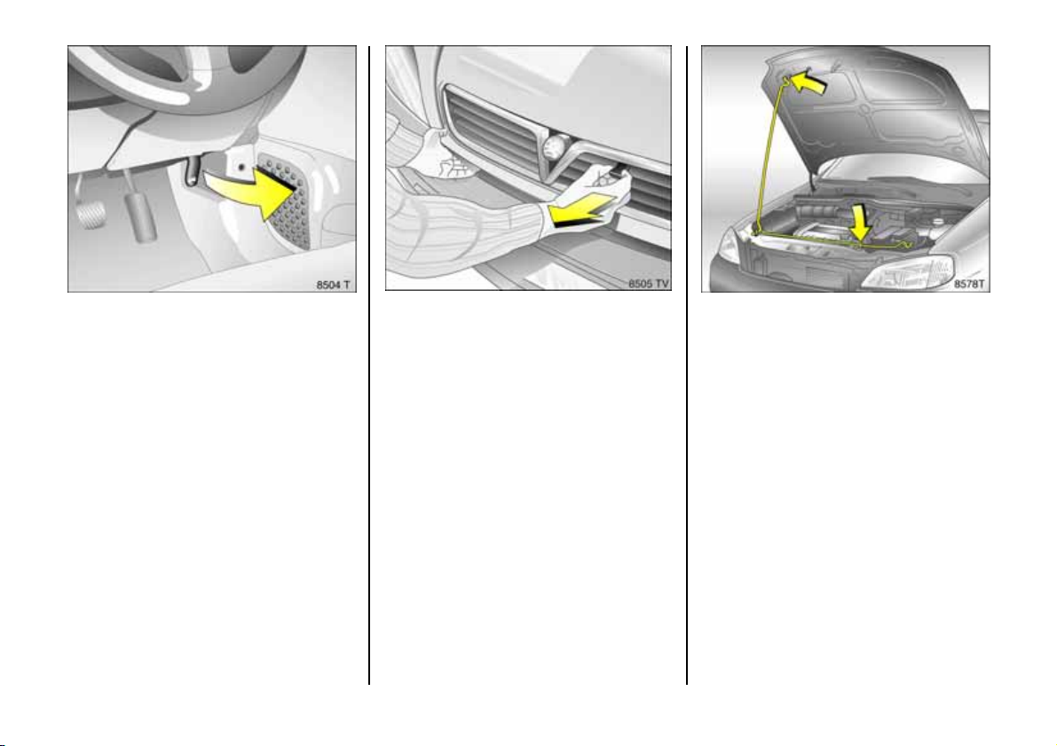
Bonnet
To open the bonnet, pull the release
lever /, located on the driver's side below
the instrument panel. The bonnet will the n
be unlocke d and will partially open. Return
release lever to its original position.
62
To open completely, locate safety catch
slightly to the right of centre as viewed
from the front: lift this upwards and op en
bonnet.
To hold the bonnet in the open position,
insert the support rod located at right
angles above the radiator grille into the
plastic-ed ged slot in the underside of the
bonnet.
Before closing bonnet, press support rod
firmly into its retaine r. Lower the bonnet
gradually and then allow it to fall into the
lock under its own weight.
The safety catch in the radiator grille must
no longer be protruding. Check that the
bonnet is locked in position by pulling at its
front edge. I f it is not engaged, repeat the
procedure.
Any dirt or snow on the bonnet can slide
down when it is opened and block the air
inlet, see pages 13 7, 143, 154.
Page 65
Seats, interior
Seat adjustment
see pages 5, 6.
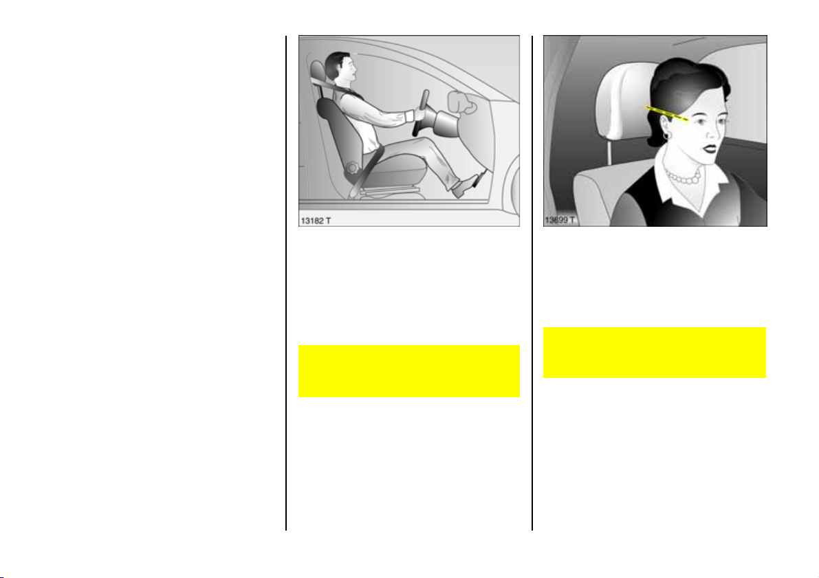
Se at p osit ion
Adjust drive r's sea t such that with th e
driver sitting upright the steering wheel is
held in the area of its upper spokes with the
driver's arms slightly bent.
The passenger seat s hould be as far bac k
as possible, with the bac krest upright.
Disre gard can lead to injuries which
could be fatal. Ve hicle passengers
should b e informed accordingly.
Head restraint position
The m iddle of the head restraint s hould be
at eye level. If this is not possible for
extremely ta ll people, set to highest
position, and set to lowest position for
small pe ople.
Disregard can lead to injuries which
could be fa tal. Vehicle passengers
should be informed ac cordingly.
Adjustm ent, see pag e 7.
63
Page 66
Head restraints
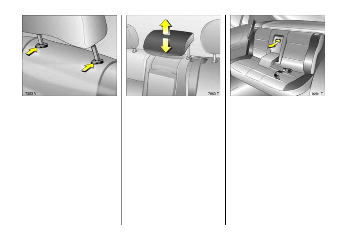
Adjustment, see page 7 .
To e nlarge luggage compa rtment (see
pages 64, 66) rem ove outer re ar head
restraints 3: Release the two springs by
pressing and detach the head restraint.
Th e rear h ead restra ints in th e C onv er tib le
cannot be adjusted or rem oved.
64
Rear centre head restraint 3
To fold down the rear seat ba ckrests or to
improve visibility if the ce ntre rear seat is
unoccupie d, the head re straint can b e
pushed all the w ay down. Release both
spr i n g s by p r es sin g.
If the centre seat is occupied, set the head
re stra int to the first or second position
according to the height of the passenger.
Luggage compartment enlargement,
Saloon/Hatch, Coupe
Fold down th e cov er behind the arm rest 3
Fold down the armrest on to the seat
cushion, pull the handle a nd tilt the cove r
forwards.
The outer seats can continue to be used for
passengers.
Cov er m ust audibly engage be hind
armr e st wh en rai s ed.
Page 67
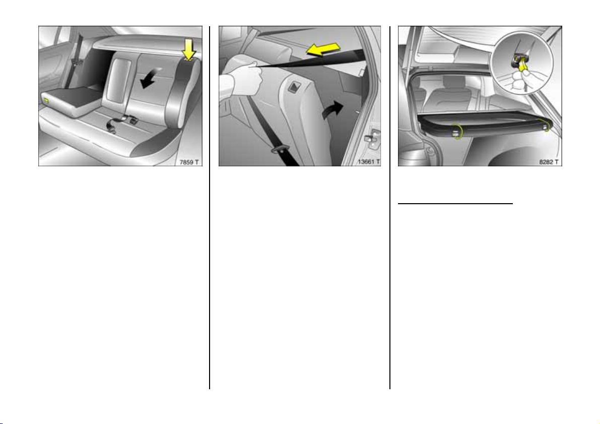
Folding d own the re ar sea t bac krests
Withdraw re ar outer h ead restraints 3 – b y
pre ssing spring catche s, se e page 64 . Move
rear, centre head restraint 3 to lowest
position – by p ressing spring catches, see
page 6 4.
Disengage one or both rear se at backre sts
using pushbuttons and fold down onto rear
seat.
To reposition re ar seat backrest, pull seat
belt forward so that it doe s not become
tra pped.
Engage rear se at back rest audibly in
position.
The three-point seat belt for the centre rear
se at 3 c an only be pulled out of the
retractor wh en the rear seat backrests are
properly locked into position.
Remov ing the lugg age compa rtmen t
cov er
3-door and 5-door Hatch only
To remove, unhook the retaining straps
from the tailgate.
Re move the cove r fro m the side guide s and
place it behind th e seat backre sts.
Fit in reverse order.
Not es on load in g
see page 7 1.
65
Page 68
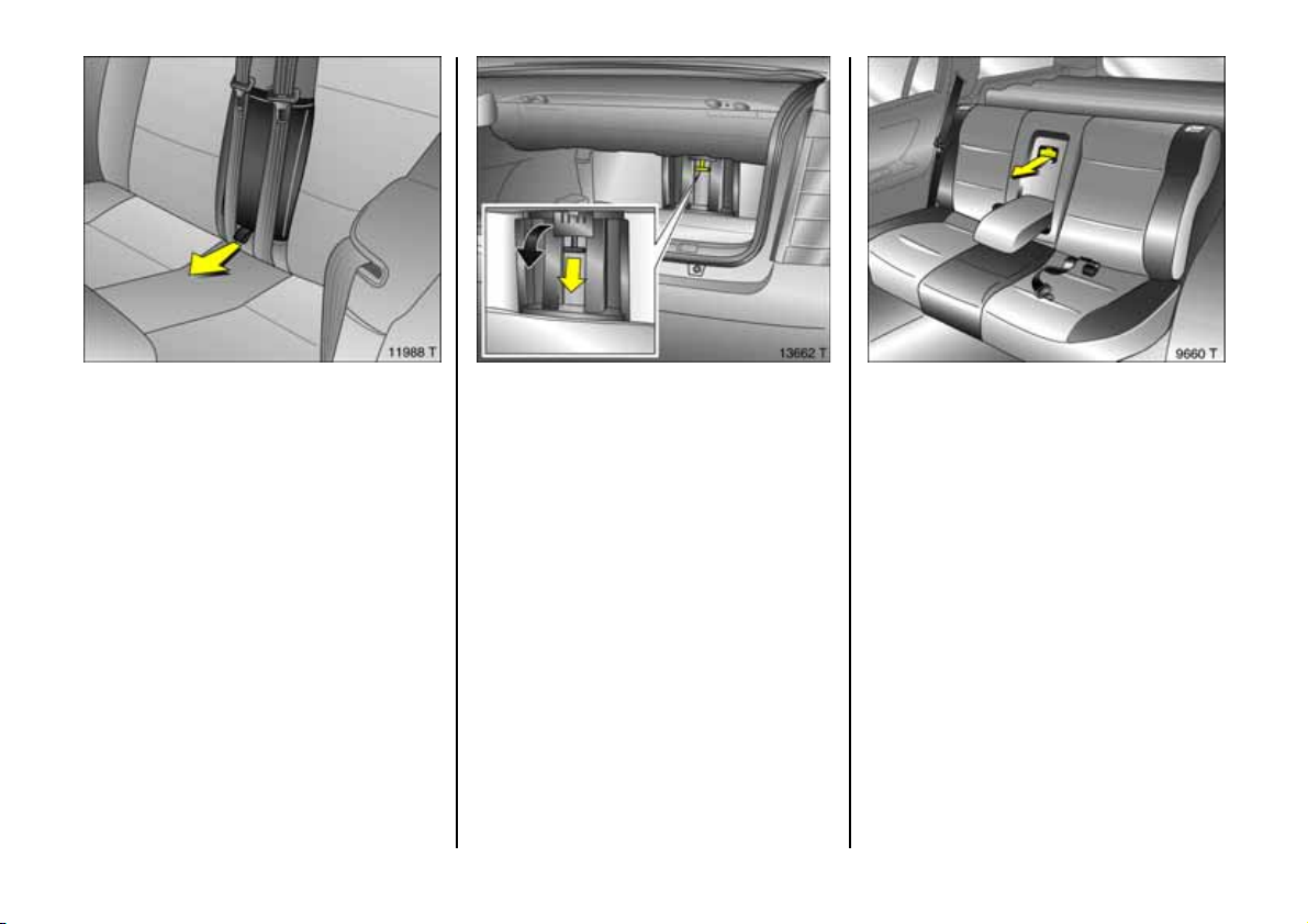
Luggage compartment en lar gemen t,
Conver tible
Fold dow n the cover behind the arm re st
Withdraw armrest using strap and place on
seat.
Armrest is attached to seat backrest by
retaining strap. To re move armrest
completely, release retaining strap fixture.
66
To open the lugg age com partment c over:
Pull the handle down a nd fold down the
cover.
To lock , swive l cover upward and audibly
engage.
Insert armrest.
Note s on loading
see page 71.
Load compartme nt enlargem ent,
Estate
Fold dow n the cover behind t he ar m re st
Fold down the armrest on to the seat
cushion, pull the handle a nd tilt the cove r
forwards.
The outer seats can continue to be used for
passengers.
Cov er m ust audibly engage be hind
armr e st wh en rai s ed.
Page 69
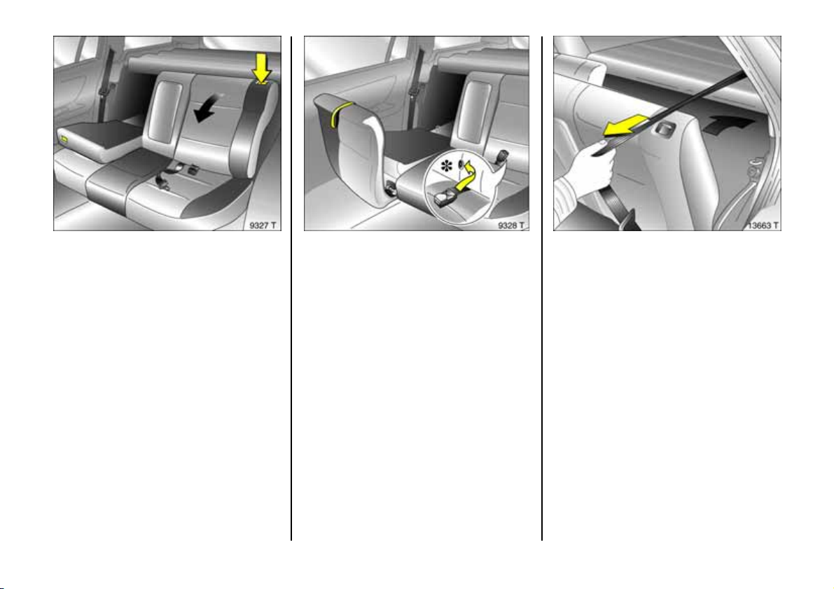
Folding d own the re ar sea t bac krests
Withdraw re ar outer h ead restraints 3 – b y
pre ssing spring catche s, se e page 64 . Move
rear, centre head restraint 3 to lowest
position – by p ressing spring catches, see
page 6 4.
Hook the seat belt buckles onto the rear
seat backrests 3.
Release one or both rear seat back rests by
pressing pushbuttons and fold onto sea t
cushion.
Raising re ar se at surfac es.
Withdraw rear outer head restraints 3 – by
pressing spring catches, s ee page 64. Move
re ar, centre head restraint 3 to lo we s t
position – b y pressing spring catches, see
page 64 .
Hook the seat belt buckles onto the rear
se a t back res ts 3.
Raise one or b oth se at cushions using
straps.
Release one or both rear seat backrests by
pressing the pushbuttons and fold down.
To re position rear se at backrest, pull seat
belt forward so that it does not become
trapped.
Engage rear seat backre st audibly in
position.
The three-point seat b elt for the centre rear
seat 3 can only be pulled out of the
retractor when the rear seat backrests are
properly locked into position.
Luggag e compart me nt cover
see page 6 8.
Sa fet y net
see page 7 0.
Not es on load in g
see page 7 1.
67
Page 70
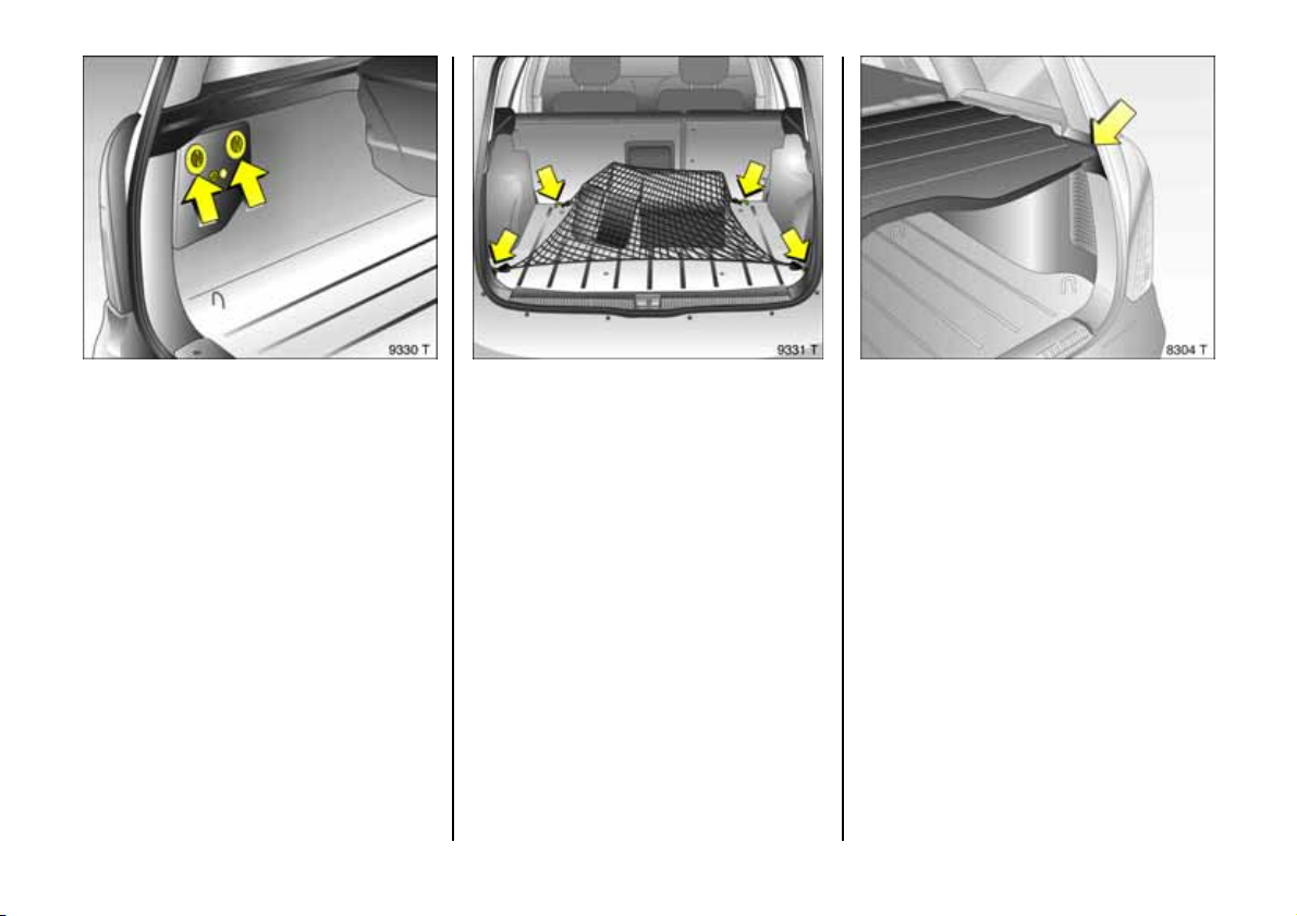
Stowage com partm ents in the
luggage compartment
Warn ing trian gle ¨ 3 and first-aid kit + 3
stowage, see pa ge 198. Stowing the spare
wheel, see page 200. Jack and vehicle tools
stowage, se e page 20 2.
68
Lashing e yes 3
These ena ble ca rgo to be secured in
position in t he lu ggage co mp artment us ing
lashing straps 3, a luggage net 3 or a
safety net 3. S afety net, see page 7 0.
Luggage compartment cover 3,
Estate
To close
Pull back lug gage compartment cover to
its limit at right and left reces ses and lock
into the retainers at the sides.
Do not place any heavy or sharp-edged
objects on the cover.
To open
Detach the cover from the retainers and
push it towards the seat backrest.
Page 71
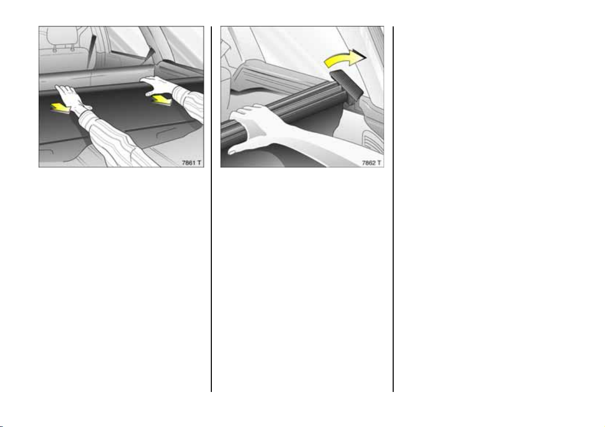
Fitti ng
Fit in reverse order to removal, when doing
so ensu re th e guides en ga ge p rop e rly in
th e guid e rails .
Remov ing
Push the cover forward towards the s eat
backrest.
Pull folded-together c over tow ards the rear
into the two guide s on the rails as far as it
will go.
Press the cover together with both hands
and pull it backwards under tension. Twist
the cover with the two guides upwards and
remove it by pushing it forward.
69
Page 72
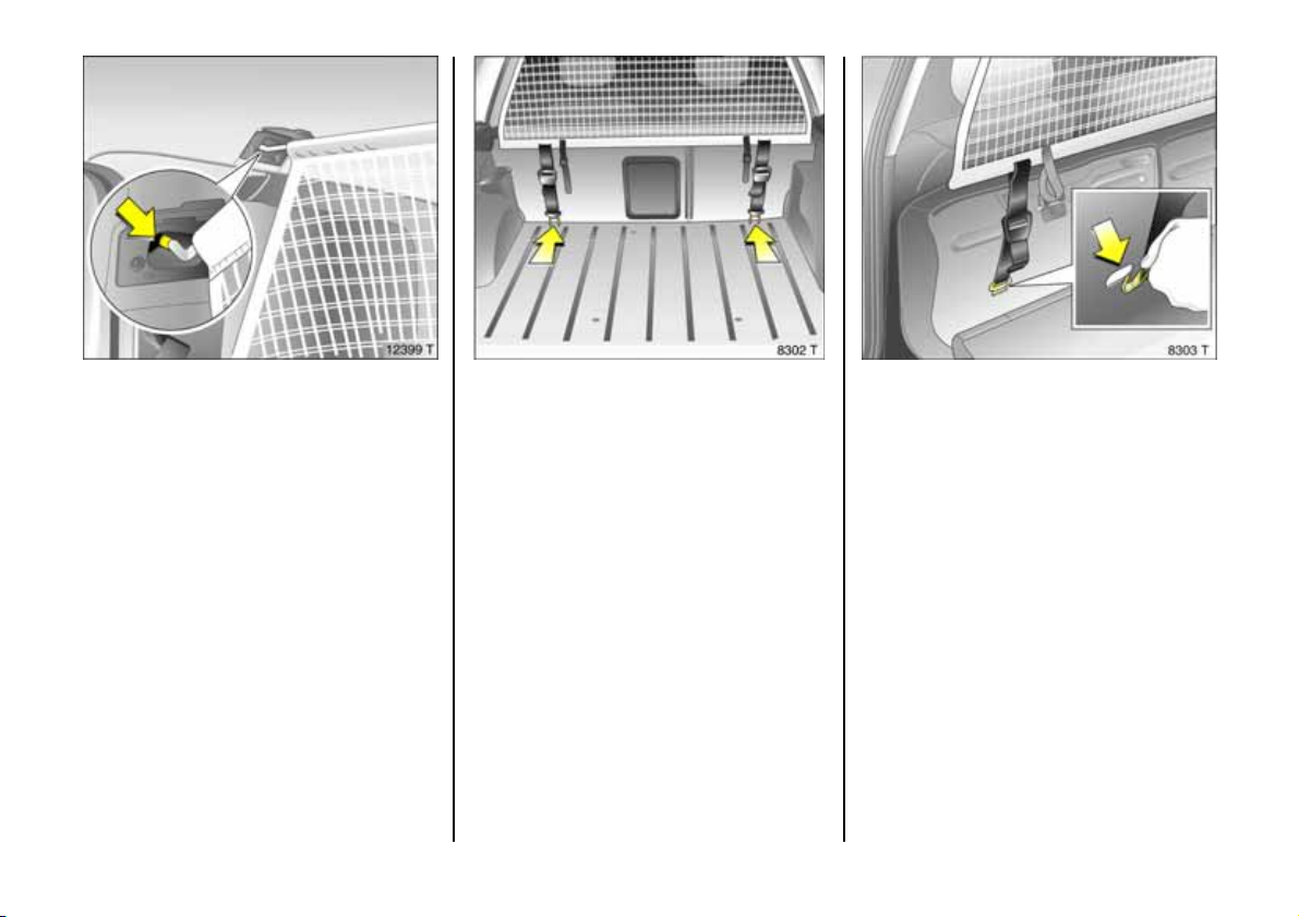
Safety net 3, Estate
The safety net ca n be fitted behind the rear
seats or, with the re ar seat backrest folded
down, behind the front seats.
Passengers must not be carried behind the
safety net.
There are tw o installation hole s in the roof
frame: Open covers. Attach rod of net at
on e sid e a n d lo ck in p lace, ex te nd ro d,
attach at other side and lock in place.
70
Fitting behind t he rear seats
Fold down both rear seat backrests, hook
straps into lashing eyes in vehicle floor and
tig hte n them. Reposition rear seat
backrests and lock them in to position.
Fitti ng behind front se ats
Pull up both rear seat cushions, hook straps
into slots on upright rear seat cushions and
tighten them. Fold down rear seat
bac krests.
Remov ing
Tilt strap length ad justers upwards and
unhook strap. Detach rod of net, close
covers.
Page 73
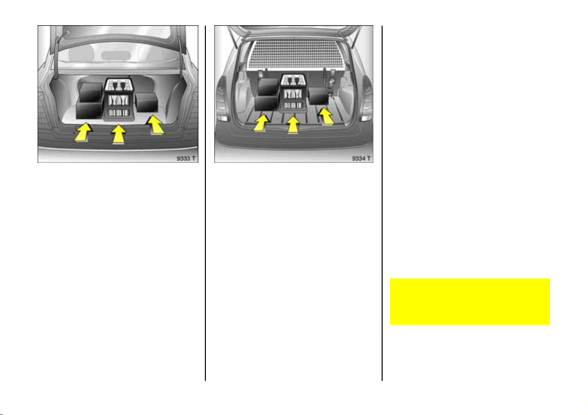
Notes on loading the vehicle
z Heavy objec ts in the luggage
com partment should be placed as far
forward as p ossible against the rear seat
backrests or, if the rear seat backrests
are folded down, ag ainst the front seat
backrests. If objects are to be stacked,
th e heavier objects should be placed at
the bottom. Unsecured objects in the
lugga ge com partment would be thrown
forward with great force in the event of
heavy braking, for e xamp le.
z Secure heavy objects with lashing
straps 3 attached to lashing eyes 3, see
page 68. I f heavy loads slip when the
vehicle is braked h eavily or driven
around a bend, the handling of the
vehicle may change.
z Saloon/Hatch, Coupe: Loose objects in
the lugg age compartment should be
secured agains t slipping usin g a
luggage net 3, see page 68 .
z E state: Always fit the safety net 3 when
transp orting objects in the luggage
compa rtment, see page 70.
z If objects are being tran sporte d in the
luggage compa rtm ent, the rear seat
ba ck res ts mus t be l o c ked in positi o n, se e
pages 65, 67.
z Do not a llow the load to protrude ab ove
the upp er edge of the rear se at
backrests, or above the upper edge of
the front seat backrests if the rear seat
backrests are folded down.
z The warning triangle 3 and first-aid kit 3
must alway s b e free ly a ccessib le .
z Do not place any objects in front of the
rear window or on the instrument panel.
They a re reflected in the glass, obstruct
the driver's view and will be thrown
through the vehicle, for instance in the
event of heavy braking.
z No objects must be placed in the area in
which the airbags inflate, as they could
cause injury when the airbags are
trig gered.
z Bulky objects should not be transported
with the luggage compa rtment open.
Otherwise poisonous exhaust fumes may
enter the vehicle. In addition, the vehicle
numb er plate is only clearly
distinguishable and c orrectly lit if th e
lug gage compartme nt is closed.
z Weights, payload and roof loa d, see
page 257.
z Driv ing with a roof load, see
pages 160, 163, 186, increases the
sensitivity of the vehicle to cross-winds
and has a de trimental e ffect on vehicle
ha ndling ow ing to the vehicle’s higher
centre of gravity.
Disregard of these notes can lead to
injuries which ma y be fatal. Vehicle
pa s seng ers sh ou ld be in f or m ed
accordingly.
71
Page 74
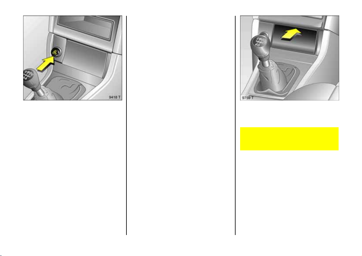
Cigarette lighter ) 3
In front cen tre console:
Press in cigarette lighter with ignition
switched on. Switches off automatically
an d eje cts onc e the el em ent is glo w ing . Pu ll
out lighter.
Accessory socket 3
The cigarette lighter socket can be used to
connect electrical accessories when the
ignition is on. If the vehicle is stationary , the
battery will be discharge d at the same
tim e. Do not damage the socket by using
unsuitable plugs.
The max imum power requirement of
electrical acce ssorie s must not exceed
120 w atts or 50 watts if the heated seats 3
are s wit ched on.
Do not connect any current-delivering
accessories, e.g. electrical charging
devices or batteries.
Elec trica l accessories connected to the
socket must comply with the
electromagnetic comp atibility
requirements la id down in DIN standard
VDE 40 839. otherwise vehicle malfunc tions
may occ ur.
Ashtray 3
To be used only for ash and not for
comb ustible rubb ish.
Disregard can lead to injuries wh ich may
be fata l. Vehicle passengers should be
informed accordingly.
Ashtray, front
The cover opens when pressed at the top.
72
Page 75
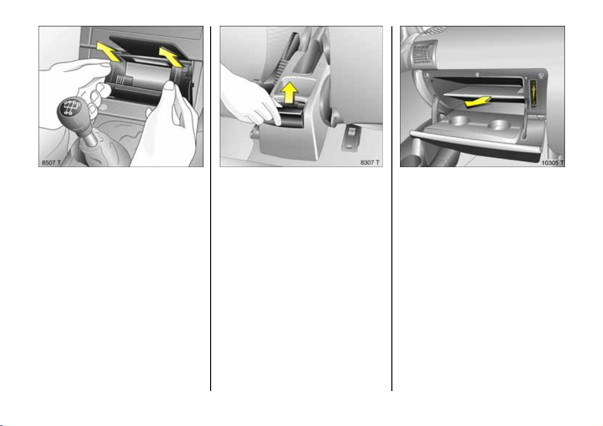
To e mpty, grip both sides of the ashtray
insert and pull upwards.
Ashtray, rea r
To op en, s wive l th e cov er u pwards .
To empty, open the cover halfway. Pull the
ashtray upwards by its cover, tilting the
ashtray slightly forward as you do s o.
Glove c o mpartm ent
To open, pull handle upwards.
The fa lse bottom 3 of the glove
compa rtment is rem ovable: disengage it
by pulling on the front rim .
When re-inserting the false bottom, slot it
onto the guide tracks at the sides and p res s
to engage in the rea r wall.
On the right-hand side of the open glove
compartm ent there is a pen holder.
Sun visors
Use the sun visor to protect from glare by
pulling it d ow n and s wivelling it to the side.
73
Page 76

Safety systems
Three-stage re straint system
Compris ing
z three-point seat belts,
z be lt tensioners at the front seats,
z a irbag sy ste m s f or driver , fro n t
passenger 3 and pas sengers in the outer
rear seats 3.
The three stag es are a ctivated in sequence
depending on the seriousness of the
accident:
z The automatic seat be lt locking devices
prevent the belt strap from being pulled
out and thus ensure that the vehicle
occupants are retained in the ir se ats .
z The front seat b elt buckle s are pulled
downwards. As a result, the seat belts
are instantaneously tightened and the
occupants are made aware of the
deceleration of the vehicle at a very early
stage. This reduces the stress placed on
the body.
z the airbag sy stems are also activated if a
head-on collis ion occurs, forming a
safety cushion for the occupants.
The airbag systems serve to suppleme nt
the three-point seat belts and belt
ten sione rs. The seat belt s must t h erefo r e
always be worn. Disregard of the se
instructions may lea d to injuries or
en dan g e r li fe. Ve hi cl e p ass en ge r s sho u ld
be informed accordingly.
Be sure to read the detailed descriptions of
the thre e-stage restra int system and the
child re straint system on the following
pag es!
74
Page 77
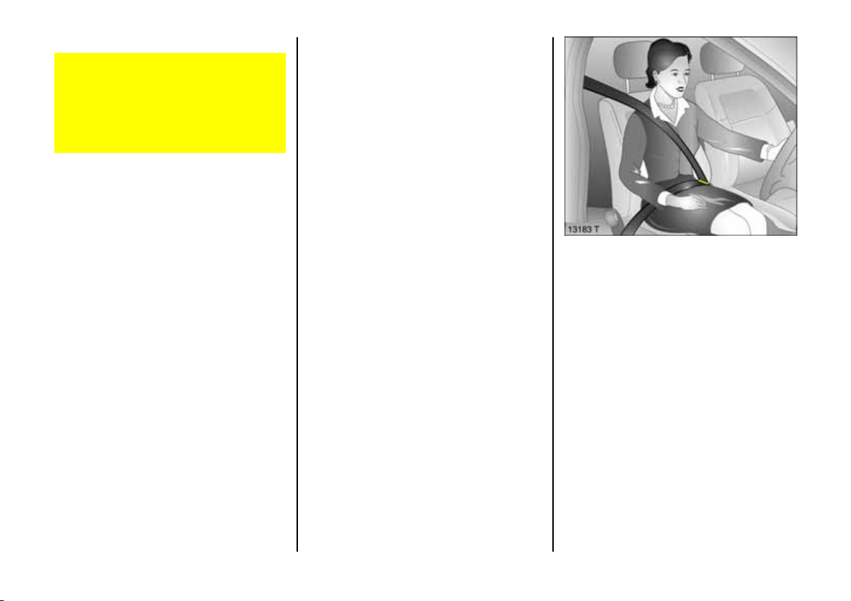
Seat belts
Alwa ys wear your seat belt, and that
means also in urban traffic and when
you are a rear seat pas senger. It can
save your life!
Pregnant women must always wear a
seat belt, see page 78.
In the e vent of an accident, persons not
wearing sea t belts e ndanger their fe llow
occupants and themselves.
Con trol indica tor X for seat belts, see
page 24 .
Seat belts are designed to be used by only
one person at a time. The y a re only
suitable for children age d up to 12 or
smaller than 150 cm if used in conjunction
with a child seat.
For children up to 12 y ears of age we
recommend the Vauxhall ch ild restraint
system, see page 90.
Three-point seat belts
The vehicle is equipped with three-point
seat belts with automatic re tractors and
locking d evice s, allowing freedom of body
movement although the spring tensioned
belts always ens ure a snug fit.
The belt has a "vehicle s ensitive retra ctor"
which is de signed to lock during heavy
acceleration or deceleration in any
direction.
75
Page 78
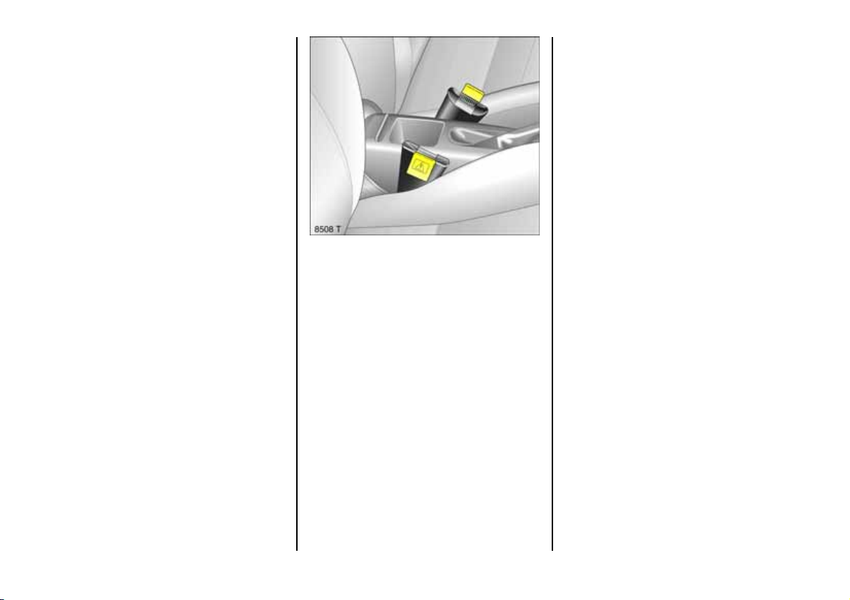
Belt tens io ners
The front sea t belt system incorporates belt
tensioners. In the event of a head -on or
rear-e nd collision, d epending on the
severity of the accident, the be lt buckles
are pulled downward s; the diagonal a nd
lap b elts are instantan eously tightened.
Periodically inspect all pa rts of the belt
system for damage and to make sure they
are functioning prope rly. Dama ged parts,
such as overstretched belts, must be
replaced by new ones.
The seat be lts remain fully operational
even when the belt tensioners have been
actuate d.
Furthe r information, see pag e 79 .
Actuati on of be lt te nsioners
is indicated by the control indicator v , s e e
next page. Actuation ma y also be
indica ted b y yellow tabs 3 on th e be lt
buckles.
The belt tensioners must be replace d after
activation. We recommend that you
consult your Vauxhall Approved Repa irer.
76
Page 79
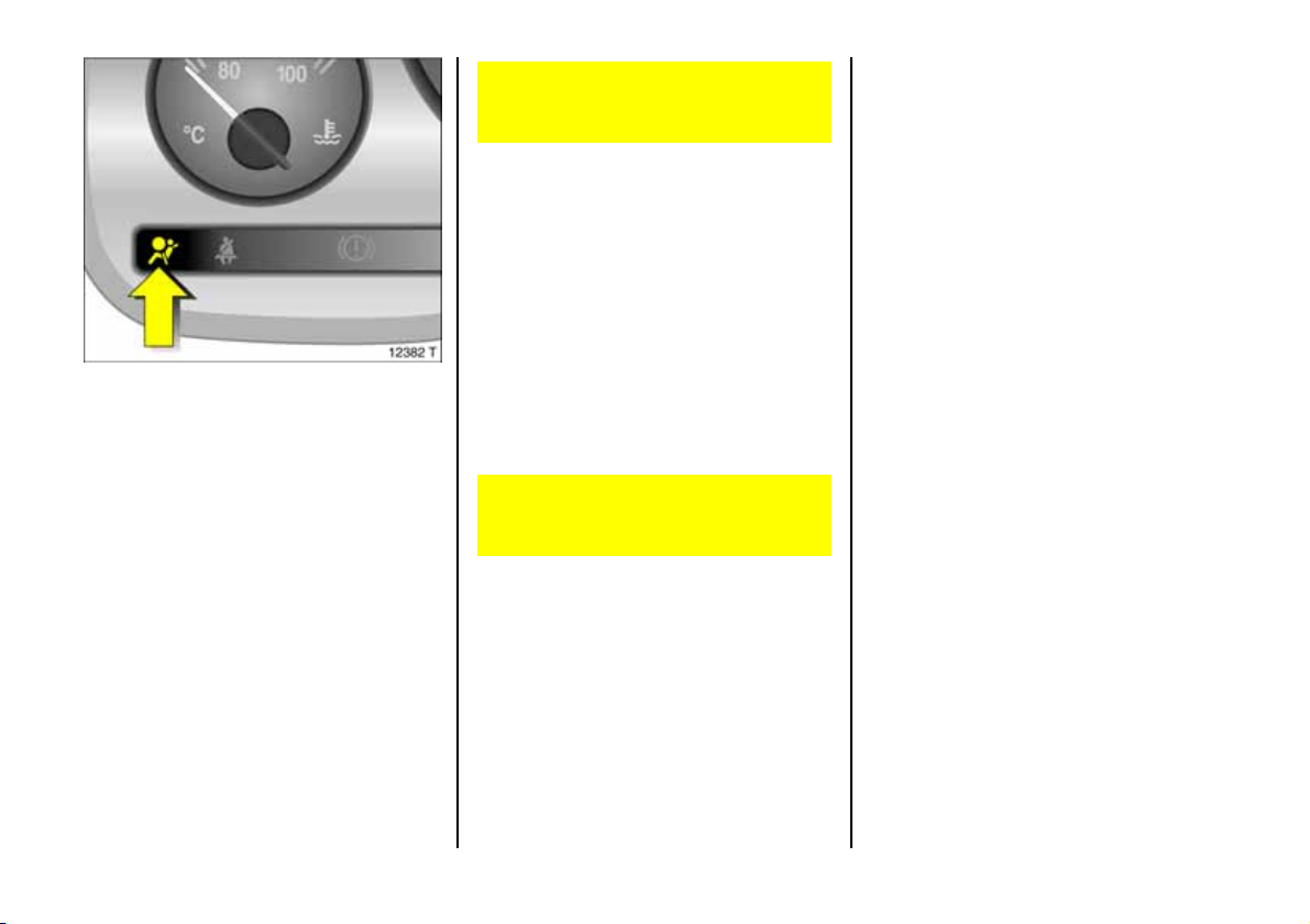
Cont rol indica tor v for belt t ension ers
The b elt tensioners are electronically
monitored together with the airbag
systems and the operation thereof is
indicated on the instrument panel by the
control indica tors v. When the ignition is
switched on, the control indica tors
illuminate for approx. 4 seconds. If they do
not illum inate, or they do n ot go off within
4 s econds, or illuminate whilst driving, th ere
is a fault in the belt tensioner system or the
airbag systems, se e page 86. The belt
tensioner or the airbag systems may not
activate if an ac cident occurs.
Have the cause of the fault remedied.
We recommend that you consult your
Vauxhall Approved Re pairer.
The system’s integrated self-diagnostics
allow s faults to be quickly remedied. Hav e
yo ur Car P a s s on ha nd wh en co n s ult i n g a
Vauxhall Approved Repairer.
Imp or tant
z Accessories not released for your vehicle
type and other objects must not be
affixed or place d within the action zone
of the belt tensioners since this may
result in injury if the belt tensioners are
triggered.
z Do not mak e any modifications to the
components of the belt tensioners, as
this will re nder the vehicle unroadw orthy.
Improper handling (e. g. removal or
installation) could cause the be lt
tensioners to be triggered. Risk of injury!
z The belt tensioner and airbag sy stem
control electronics can be found in the
centre console area. In order to avoid
malfunctions, do not store magnetic
objects in this area.
z We recommend that you entrust front
seat removal to your Vauxhall Approved
Repairer.
z The belt tensioners only actuate once.
Please replace belt tensioners that have
been triggered. We recom mend that you
consult your Vauxhall Approved
Repairer.
z Applicable directives must a lways be
ob se r ved wh en dis pos ing of th e vehicle.
For this reason, disposal should be
performed by an authorised recycling
company. We recommend that you
consult your Vauxhall Approved
Repairer.
77
Page 80
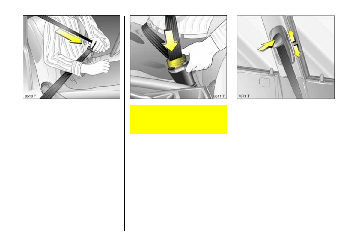
Usin g t he b elts
Fitting seat belts
Pull the belt out of the retractor and guide
it across the body, making ce rtain that it is
not twisted.
Insert latch plate into buckle. Backre st
must not be tilte d too far back, since this
would affect the operation of the seat
belts; recommended tilting angle app rox.
25°. The lap belt m ust be straight and lying
snugly against the body. Tighten be lt at
frequent intervals whilst driving by tugging
diagonal part of belt.
78
On pregnant women in particular, the
lap belt must be positioned as low as
possible ac ross the pelvis so as not to put
too much pressure on the abdomen.
Bulky clothing prevents the belt from fitting
properly. The belt must not rest against
ha rd or fragile obje cts in the pockets of
you r clothing (e.g. ballpoint pens, ke ys ,
spectacles) be cause these could cause
injury. Do not place any objects (e.g.
ha ndbags, mobile phones) between the
belt and your body.
Height adjustment 3
of front seat belt upper a nchorage points:
1. Do n ot adjust whilst driving.
2. Pull belt out slig htly.
3. Press button down or push belt guide up.
4. Se t des ired height.
5. Allow anchorage to lock aud ibly into
position.
Adjust height such that the be lt passe s
over the occupant’s shoulder and rests
aga inst the shoulder. It must not pass over
the neck or upp er arm, see page 75,
Fig. 13183 T.
Page 81
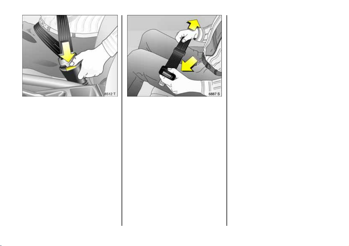
Testing the belts
Plea se c h eck a ll par ts of th e b elt s ys t em
occasionally for dama ge a nd correct
operation. Have damage d parts replaced .
In ca se of an accide nt, replace
overstretched belts and triggered belt
tens ioners. We recom mend consulting your
Vauxhall Approved Re pairer.
Do not perform any altera tions on the
belts, their anchorages, the automatic
retractors or the belt buckles.
Mak e sure that b elts are not da mage d or
trapped by sharp-edge d objects.
Remov ing the belt
To rem ove the be lt, depress the red
pushbutton on the buckle; the belt will
retract autom atically.
Lap be lt 3
In centre of rear s eat: to adjust the length,
press the top of the la tch plate.
Three-point seat bel t 3 on centre re ar
se at
The belt can only be pulled out of the
retractor wh en the rear seat backrests are
prop er ly loc k ed in to th eir b racket s , s ee
pages 65, 67.
79
Page 82
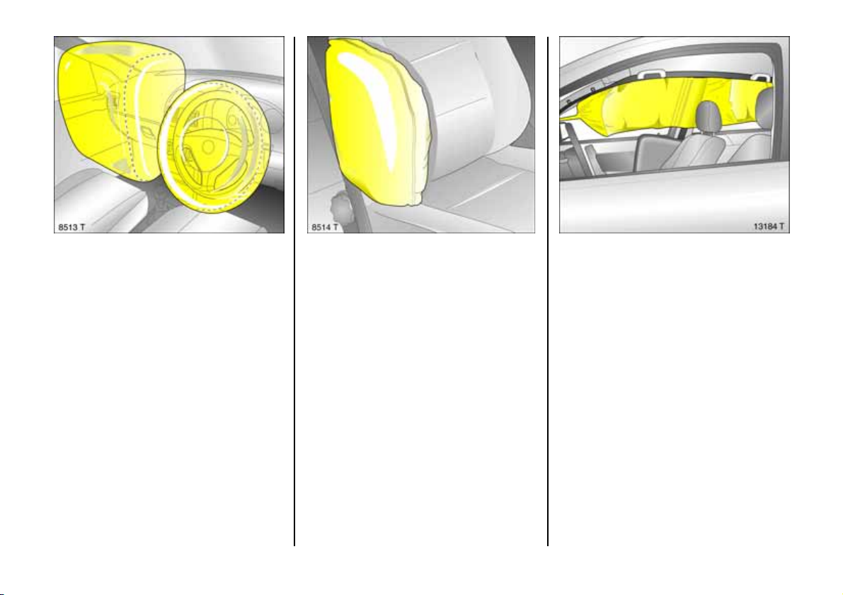
Vau xhall Fu ll S ize A ir bag s yste m
The Vauxhall Full Size Airbag S ystem
comprises several individual systems.
Front Airbag System
The front airbag system will be triggered in
the eve nt of a serious ac cident involving a
frontal impact and forms safety cushions
for the driver and fron t passenger. The
forward movement of the driver and front
passenger is checked and the risk of
injuries to the upper body a nd head
thereby substantially reduced.
80
Side Airb ag System 3
The side airbag system is triggered in the
event of side-on collisions and forms safety
cushions for the driver and front passenger
in th e respecti ve fr o n t do o r ar ea. The risk o f
injury to the upper body in the event of a
side impac t is thereby substantially
redu ced.
Head Airbag System 3
The he ad airbag system is triggered in the
event of side-on collisions and forms a
safety cushion in the head area on the side
of t h e ve hicle af fe cted. The risk of injury to
the head in the event of a side impact is
thereby subs tantially reduced.
Page 83
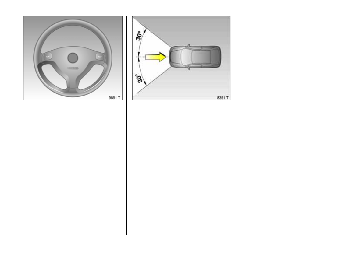
Vauxhall Full Size Airbag System
Front Airbag
Th e fro nt a irbag s ystem is iden tif ied by the
word AIRBAG on th e s teering whee l an d
above the glove compartment 3.
The front airbag system comprises:
z an airbag with inflator in the steering
wheel and a second one in the
instrument panel,
z th e control electronics with impact
se ns or ,
z the airbag systems control indicator v in
th e instrument panel.
z seat occ upancy recognition 3,
z the control indicator for Vauxhall child
restraint systems y with tran sponders 3
in the courtesy lamp.
The front airb ag system will be trigg ered:
z depending on the severity of the
accident,
z de pending on the type of impact,
z within the range shown in the illustration,
z independently of the s ide airb ag
system 3 and h ead airbag system 3.
Exception:
Passenger sea t with seat occupancy
recognition system 3 . The seat occupancy
recognition system deactivates the
passenger front and side airbags if the
passenger seat is unoccupie d or a
Vauxhall child restraint s ystem with
transponders 3 has be en fitted to the
passenger seat. S eat occupa ncy
recognition, see pag e 8 6. Vauxhall child
restraint system w ith transponders 3, see
pag e 96.
Examples of events triggering the front
airbag system:
z Impact against a non-y ielding obstacle:
the front airbags are trigg ered at low
vehicle speed.
z Impact against a yield ing obstacle:
(such as another vehicle): the front
airbags are only triggered at a higher
vehicle speed.
6
81
Page 84
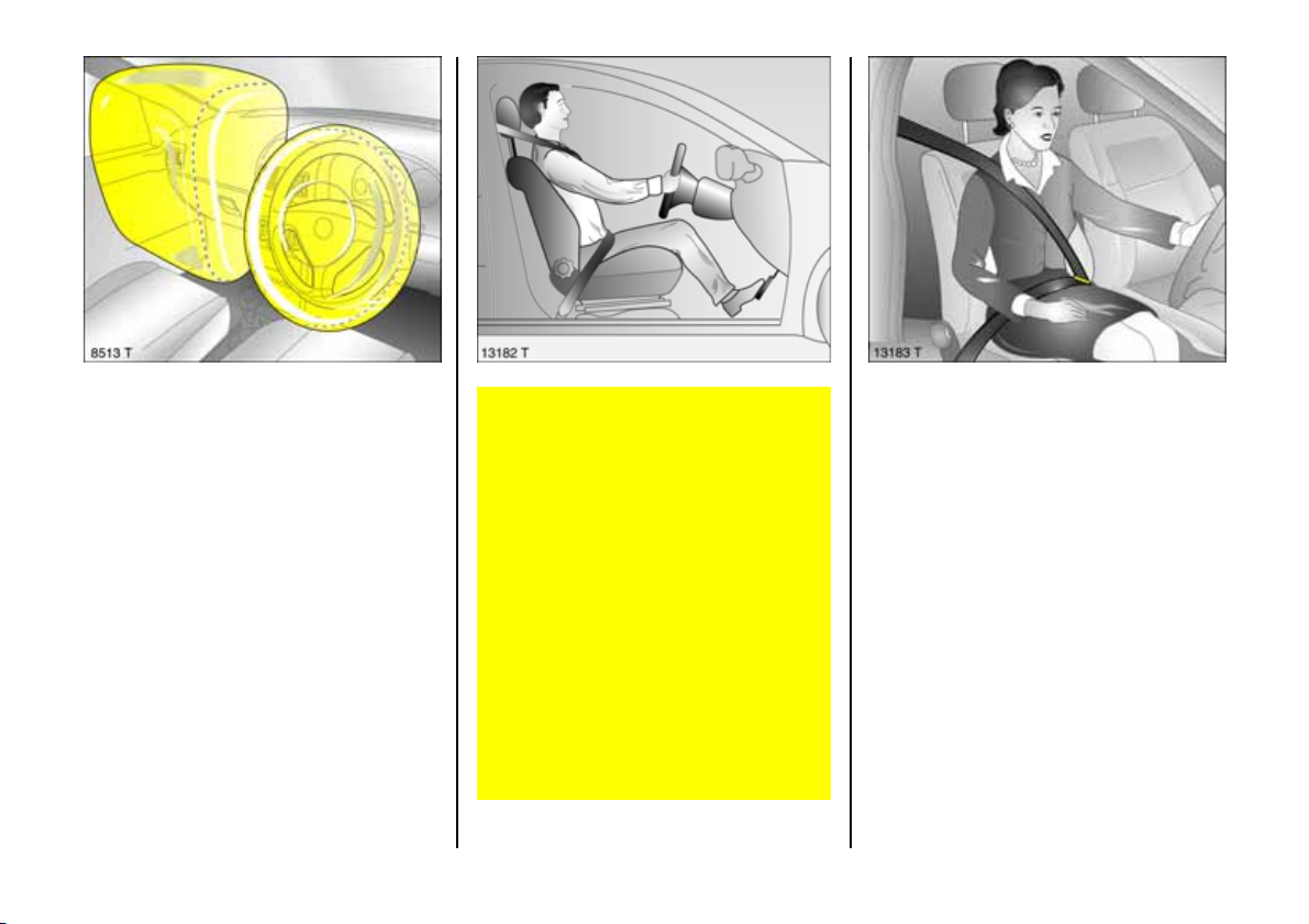
When trigg ered, the front airbags inflate in
milliseconds and form a safety cushion for
driver an d front pas senger. The forward
movement of the driver and front
passenger is checked and the risk of
injuries to the upper body a nd head
thereby substantially reduced.
No im pairment of view will occur, because
the a irba gs inflate and de flate so quic kly.
82
The front airbag system provides
optimum protection when the seat,
backrest and head restra int are correctly
adju s ted: Adj ust the dr iver's se at
according to the occupant's height such
that with the driver sitting upright the
steerin g wheel is held in the area of its
uppe r sp ok es with th e driv er 's ar ms
slightly bent. The passenger seat shou ld
be as far back as possible, with the
backrest upright (see pages 5, 63). Do
not place the head, body, hands or feet
on the covers of the airbag systems.
Do not place any objects in the area in
which th e airb ags inflate . Important
information, se e page 88 .
Th e thr e e-poin t s eat be lt must b e
correctly fitted, see page 78.
The front airbag sy stem will not be
triggered in the event of
z the ignition is switched off,
z minor frontal collisions ,
z accidents in which the vehicle overturns,
z collisions involving a sid e or rear impac t
where it would not be of benefit to the
occupants.
Page 85
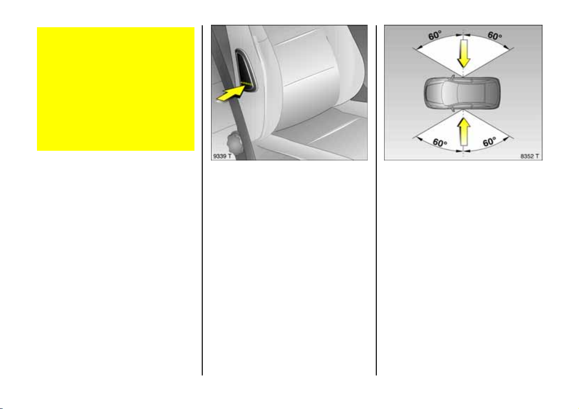
Seat belts must therefore always be
worn. The front airbag system se rves to
supplement the three-point seat belts. If
you do not wea r your seat be lt you ris k
being seriously injured, or even thrown
from th e vehicle, in th e ev ent o f an
accident.
In the event of an accident the belt helps
to keep you in the correct seating
position, so that the front airbag s ystem
can pr o vide you wit h ef fe cti ve
protection.
In addition, the front airbag system will not
be triggered for the front passenger in
versions with seat occupancy recognition 3
if
z th e f ront pa ssenge r's seat is unoccupie d,
z th ere is a prop erly fitted Vauxhall child
restraint system with transponders 3.
Seat occup ancy recognition, see
page 86. Vauxhall child restraint system
w i th tr a n s p o n d e r s 3, see page 96.
Side Airb ag 3
The side airbag system is identified by the
word AIRBAG on the outboa rd sides of the
front seat backrests.
The side airbag system comprises:
z an airbag with inflator in the back of th e
driver's and front passenger's seat
respectively,
z t h e contro l e lect ronics,
z t h e sid e i m pact se n so r s,
z the airbag systems control indicator v in
the instrument panel,
z seat occ upancy recognition 3,
z the control indicator for Vauxhall child
restraint systems y with transpon-
ders 3 in the courtesy lamp.
The side airbag sy ste m will be trigge red:
z depending on the severity of the
accident
z depending on the type of im pact
z within the range s hown in the illustration
on the driver's door or front passe nger
door
z independently of the front airbag
sy ste m.
Exce ption: Pa ssenger seat with seat
occupancy recognition system 3. Th e se at
occupancy recognition system deactivates
the pa ssenger front and side airbags if the
passenger seat is unoccupie d or a
Vauxhall child restraint s ystem with
transponders 3 has be en fitted to the
passenger seat. S eat occupa ncy
recognition, see pag e 8 6. Vauxhall child
restraint system w ith transponders 3, see
pag e 96.
83
Page 86
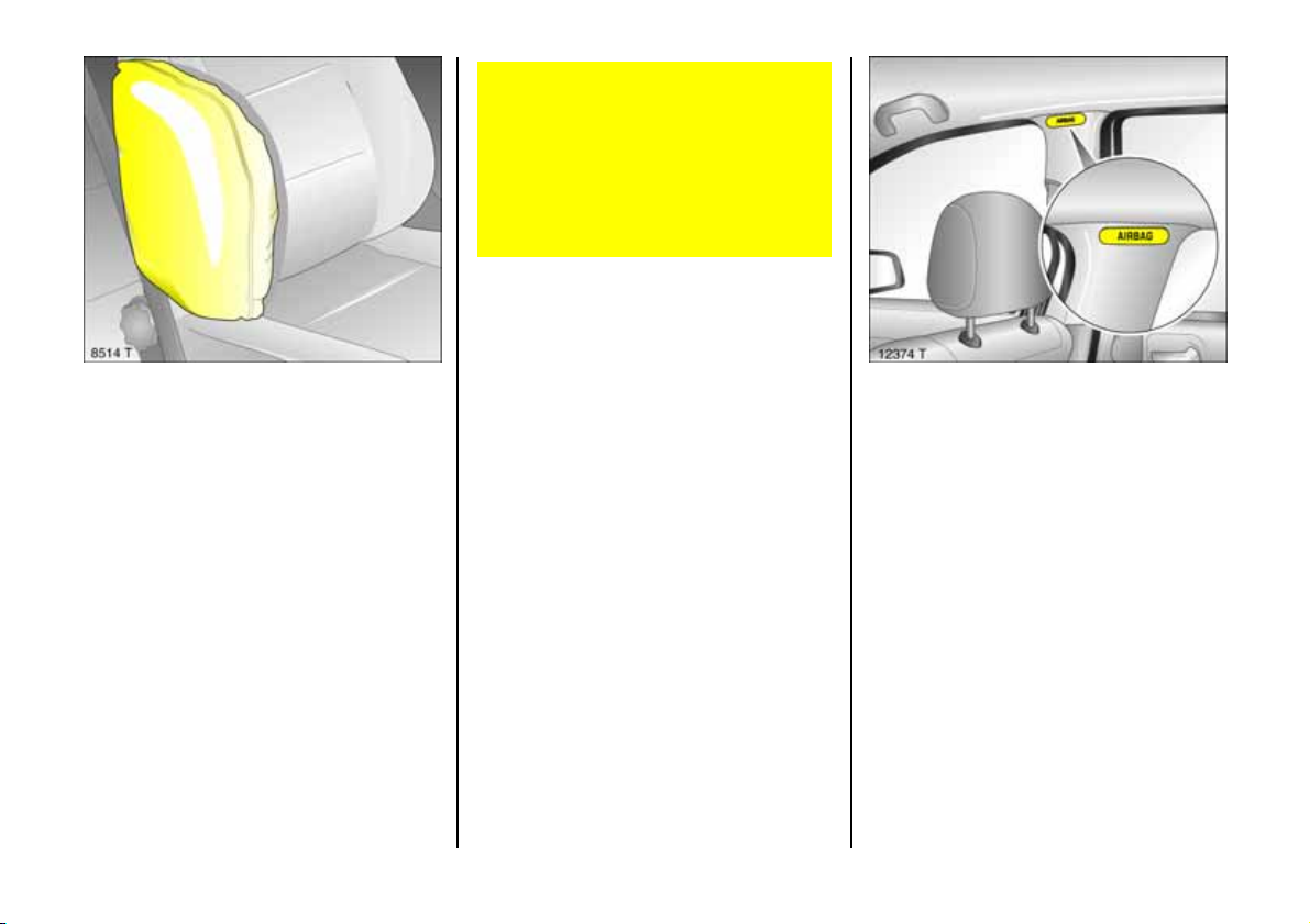
When triggered, the side airbag inflates in
milliseconds to form a safety cushion for
th e d riv er or f r o n t pas se n ger in the
respective door area. This substantially
reduces the risk of injury to the upper body
in the event of a side-on collision.
There must be no objects in the area in
which the airbag inflates or in the a rea
between the seat backs and the ve hicle
body. Do not place the hands or arms on
the covers of the airbag systems.
Important information, see page 88.
Th e thre e-p oin t se at b elt must a lways be
correctly fitted, see page 78.
The side airbags will not be triggered in the
eve n t o f
z the ignition is switched off,
z frontal collisions,
z accidents in which the vehicle overturns,
z collisions involving a re ar impac t,
z collisions involving a side imp act outside
the passenger cell.
In addition, the side airbag system will not
be triggered for the front passenger in
versions with seat occupa ncy recognition 3
if
z the front passenger's s eat is unoccupied,
z there is a prope rly fitted Vauxhall child
restraint system with transponders 3.
Seat occupancy recognition, see
page 8 6. Vauxhall child restraint system
with transponders 3, see pag e 96.
Head Airbag 3
Th e head air ba g s ystem is ide n t ifie d by t h e
word AIRBAG on the roof pillar trim.
The head airbag system comprises:
z an airbag w ith inflator in the roof frame
on the dr iver's an d front passe ng er's s ide
respectively,
z the control electronics,
z the side im pact sensors,
z the airb ag systems control indicator v in
the instrument panel.
84
Page 87
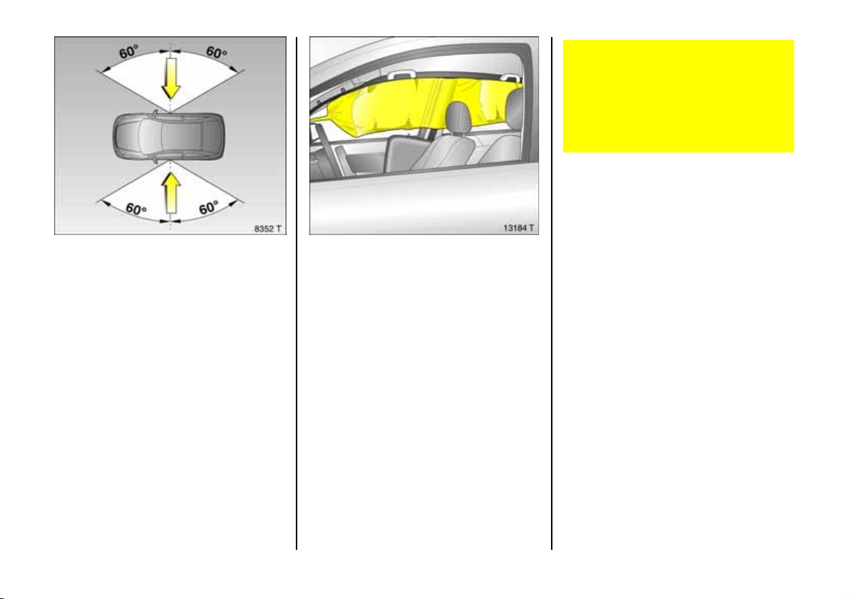
The he ad airbag sy stem will be triggered:
z depending on the severity of the
accident,
z depending on the typ e of impa ct,
z within the range shown in the illustration
on the driver's door or front passenger
door,
z together with the side airbag sy stem,
z independently of the front airbag
sys tem .
When triggered, the head airbag inflates in
milliseconds to form a safety cushion in the
head a re a on th e side o f the v eh i cle
affected. This substantially reduces the risk
of injury to the head in the event of a sideon c ollision.
The re m u st be no obj ec ts in th e area in
which the airbag inflates. Do not place
the hands or arms on the covers of the
airbag systems. Important information,
see page 88.
The thre e-point s eat be lt mus t alway s be
correctly fitte d, see page 7 8.
The head a irba gs will not be trigge red in
th e eve n t of
z the ignition is switched off,
z frontal collisions,
z accidents in which the vehicle overturns,
z collisions involving a rear impact,
z collisions involving a side impact outside
the passenger cell.
85
Page 88
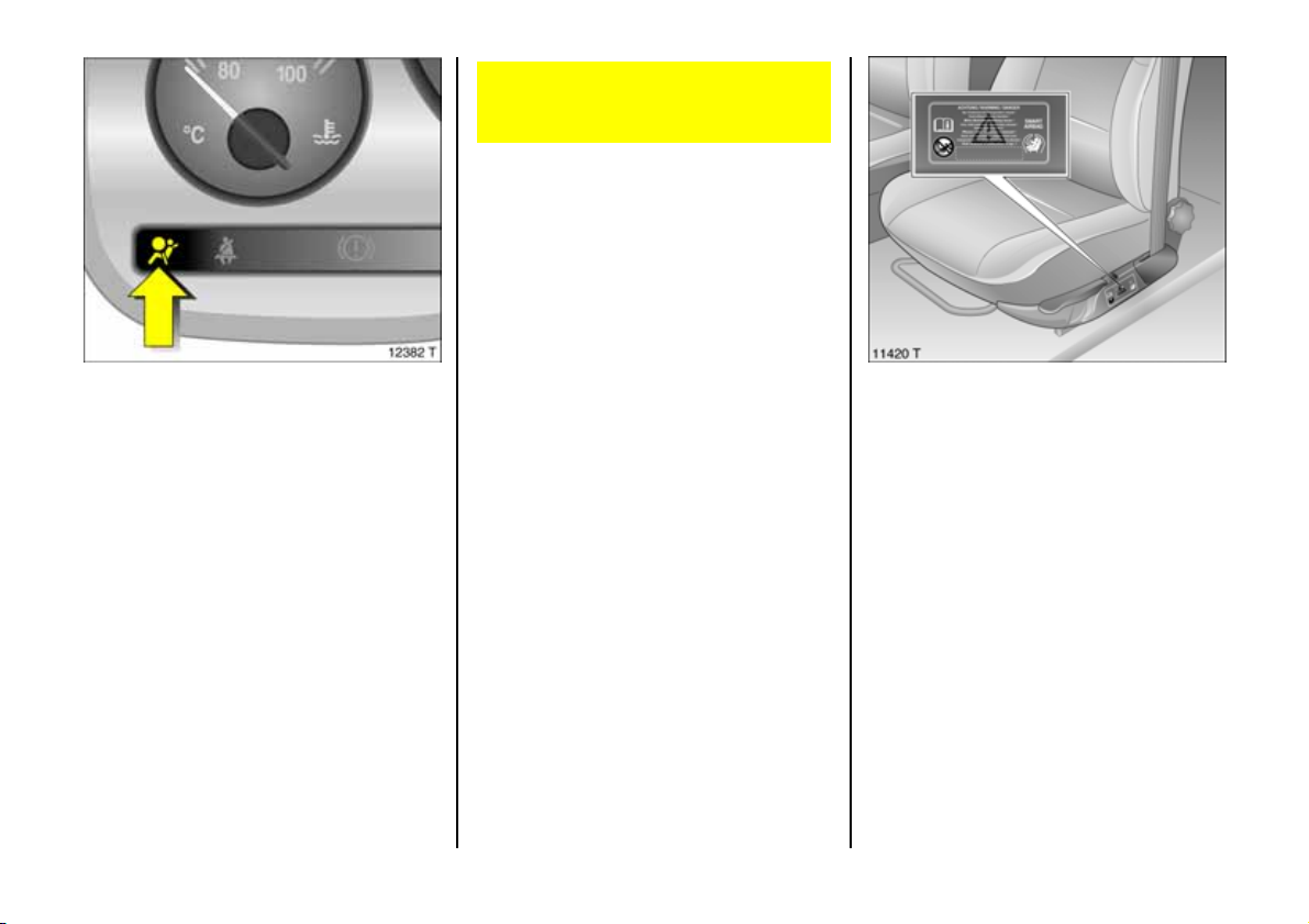
Cont rol indica tor v for Airbag Systems
The a irbag systems are monitored
electronic ally together with seat
occupancy recognition 3 and the belt
tensioners. Their ope rational readiness is
shown by control ind icator v in th e
instrument panel. When the ignition is
switched on, the control indicator lights up
for approx. 4 seconds. If it does not light
up, if it does not go out after 4 seconds or
if it lights up while driving, there is a fault in
the airbag systems, seat occupancy
recognition 3 or the belt tensioners, see
page 7 7. The systems may fail to trigg er in
an accid ent.
Have the cause of the fault remedied.
We recommend that you consult your
Vauxhall Approved Re pairer.
The system’s integrated self-diagnostics
allow s faults to be quickly remedied. Hav e
yo ur Car P a s s on ha nd wh en co n s ult i n g a
Vauxhall Approved Repairer.
Seat occup ancy recognition 3
The seat occupa ncy recognition system
deactivates the front and side passenger
airbags if the front passenger seat is
unoccupie d or a Vauxhall child restraint
sy st e m wi th tr an s p on d er s 3 has be en f itted
to the front passenger s eat. The head
airbag system remains activated.
The con trol indicator for seat occupancy
recognition is located in the courtesy lamp.
If this control indicator lights up afte r the
ignition is s witched on for approx.
4 se c on d s, t h e ve hi cl e i s e qu i pp e d wi th se a t
oc cupancy recognition, see pag e 87,
Fig. 11414 T.
This control ind icator lig hts up
permanently after the ignition is switched
on w he n a V auxhall child re straint s ystem
with transponders 3 is fitted as soon as the
system has detected the seat. Only then
can the child restraint system be
tra nsported on the front passenger seat.
In ad dition, vehicle s with seat occupancy
recognition can be id entified by the sticker
on the front passenger seat.
Vauxhall child restraint s ystems with
transponders 3 are automatically
detected if correctly fitted to the front
passenger seat. When these child restraint
systems are being used on the front
passenger seat, the front and side airbag
sys tems for t h e fron t passe n ger seat are
deactivated. The he ad airbag system
remains activated. Pay a ttention to the
seat occupancy recog nition 3 control
indicator, see pag e 87.
86
Page 89
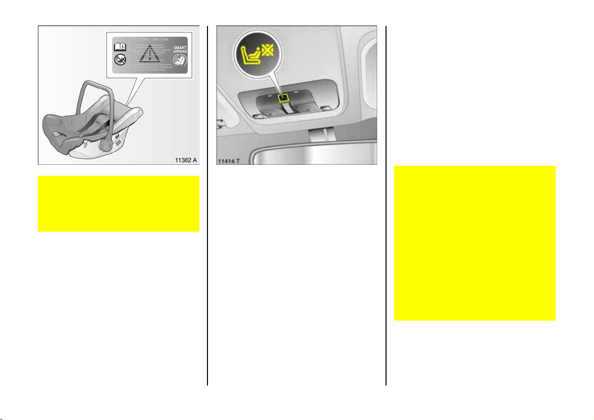
If the control indicator does not illuminate
with a corre ctly ins talled child restraint
system there is a fault - risk of fatal injury to
the child . F it child restraint system to rear
seat. Have cause of fault remedied. We
recommend that you consult your Vauxhall
Approve d Re pairer.
If no V auxhall child re straint system w ith
transponders 3 is installed the control
indicator must neither illuminate nor flas h,
since the passenger side airbag systems
would n ot be trig gered. Have the cau se of
fault remedied. We recommend that you
consult your Vauxhall Approved Repairer.
Only Vauxhall child re straint systems
with transponders 3 can be fitted on the
front passenger seat; the use of systems
withou t transponders poses a danger to
li f e .
Vauxhall child restraint systems with
transponders 3 ar e iden tif ied by a sticke r.
Cont rol indica tor y for Vauxha ll
child restraint systems
wi th transponders 3
The p resence of a Vauxhall ch ild restrain t
system with transponders 3 is indicated
after the ignition has been switched on by
permanent illumin ation of the control
indicator y in the courtesy lamp, as soon
as the seat occupancy recognition s ystem
has detected the child restraint system.
If the control indicator does n ot illuminate
whilst driving, the front and side airba g
ha ve not been d eactivated on the
passenger side. Risk of fatal injury to the
child - fit child restraint system to rear seat.
Have cause of fault rem edied. We
recommend that you consult your Vauxhall
Ap proved Repairer.
If the child restraint system is not fitted
corre ctly or the transponders are faulty,
the control indicator flashes. C heck that
the child restraint system is fitted correctly.
Fitting child restraint system with
tra nsponders 3, see pages 96 to 9 7.
If the Vauxhall child restraint s ystem
with tra nsponders 3 ha s b een fitted
according to the instructions, the control
indicator for Vauxhall restraint systems
with transponders must light up in the
courtesy lamp when the ignition is
swi t c h e d o n .
If the control indicator does not
illuminate whilst driv ing , the airb ag
sy st e ms ha ve no t bee n dea ctiv at ed on
the passenger side. Risk of fatal injury. In
this case, fit ch ild restraint system to rear
seat. Have cause of fault remedied . We
recommend that you consult your
Vauxhall Ap proved Repairer.
87
Page 90

Im portant
z No accessories or objects must be placed
in the area in which the airbag s inflate,
as the y could cause injury when the
airb ags are triggered.
z Do not place any objects between the
airb ag systems and the vehicle
occ upa nts ; d ang er o f i n j ury .
z Use the hooks in the roof frame only to
hang up light articles of clothing or c oat
hange rs. Do not place any objects in the
pockets of the hanging items – risk of
in j u r y.
z The airbag systems and belt tensioner
control electronics can be found in the
centre console area. In ord er to avoid
malfunctions, do not store magn etic
ob jects in this area.
z Do no t s t i c k a ny thin g o n t h e ste eri n g
wheel, instrument p anel, front seat
backrests or roof frame in the vicinity of
th e airbags, or on the front pa ssenger's
seat cushion, or cover any of those areas
wi th ot h e r ma t e ri al s .
z Use only a dr y cl ot h o r i nt e rior c l e an er to
clean the steering wheel, instrum ent
panel, front s eat b ackrests, roof fram e
and seat cushion of the front passenger
seat. Do not use any aggressive cleaning
agents.
z O nly protective cove rs whic h are
approved for y our Astra with s ide
Airbag 3 may be f itted on th e front
seats. When fitting the protective co vers,
make sure that the airbag units on the
outboard sides of the front seat
backrests a re not covered.
z The airbag systems are triggered
independently of each other depending
on the se verity of the accident and the
type of impa ct. The side airbag system
and the head airbag system are
triggered together.
z E ach airbag can be triggere d only once.
Once triggered, an airbag must be
replaced without delay. We recomm end
that you consult your Vauxhall
Approve d Re pairer.
z T h e s pee ds, d i re ct io n s o f m ov eme n t an d
de form ation p rope rties o f the v eh i cl es ,
and the properties of the obstacle
concerned, determine the severity of the
accident and triggering of the airbags.
The degree of da mage to your vehicle
and the resulting repair costs alone are
not indicative that the criteria for
triggering of the airbags were met.
z Do not perform any alterations on the
components of the airbag system, as this
would render the vehicle unroadworthy.
The systems can be triggered abruptly
an d caus e inju r y i f th ey are ha nd le d
improperly.
z We re com men d having t h e s t ee r ing
wheel, the instrument panel, all pane lling
parts, the door seals, the handles and
the front seats removed by your
Vauxhall Ap proved Repairer.
z Applicable directives must a lways be
ob se r ved wh en dis pos ing of th e vehicle.
For this reason, disposal should be
performed by an authorised recycling
company. We recommend that you
consult your Vauxhall Approved
Repairer.
88
Page 91
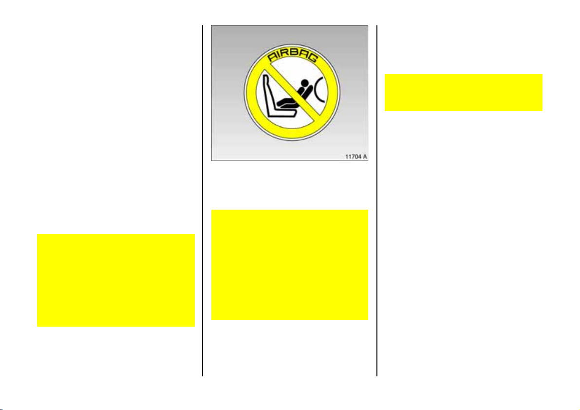
z Persons weighing less than 35 kg should
on l y t ra vel on th e r ea r se at s. T his do e s
not ap ply to children who are trav elling
in child restraint system s with
tr an s p o n de rs 3.
z In vehicles with se at occupancy
recognition 3, do not plac e any heavy
ob jects on the front passenger's seat
otherw ise the airbag systems for the
front passenger's seat may be trigge red
in th e ev ent of a n acc id ent.
z In vehicles with se at occupancy
recognition 3, to prevent m alfunctions
do n ot us e p rotective cove r s or s eat
cushions on the front passenger's seat.
z When using a Vauxhall child restraint
system with tra nsponders 3 on the front
passenger's se at, in order to prevent
malfunctions, no objects (e.g. plastic
shee t, s ticke rs or h e ated mat s) m ay b e
placed under the child restraint system.
Child restraint systems as well as othe r
heavy objects must never be carried on
th e la p of passengers; risk of fatal injury.
If carried in this way, child re straint
sys t em s wi t h tra n spo nders 3 in vehicles
with seat occupancy re cognition 3 could
le ad to front passenger airbag systems
not being triggered in the event of an
accident.
Vehicles with front passenger airbag can
be identified by the word AI RBAG abov e
the glove compartment and the warning
sticker on the side of the instrument panel,
vis ible when th e pass e nge r do or is o p en .
Vehicles with side airbag 3: No child
restraint system 3 m ay be fitted on the
f ron t p a ss en ge r 's se a t ; r is k of fa ta l in j ury .
A v ehicle with side airbags can b e
identified by the word AIRBAG on the
outboard sides of the front seat backrests.
Seat occupancy recognition 3, s e e
pag e 86.
Use of child res traint sy stems 3 on
passenger seat in v ehicles with ai rbag
systems 3 and without se at occ upancy
recogn ition 3
Vehicles with front pas senger airba g 3
but without side airbag 3: R ear-facing
child seats (safety cradle and safety
seats for weight ranges 0 and I, see
following pages) must not be fitted on
the front pass enger seat; danger to life.
Forw ard-facing child seats (safety seats
for weig ht ranges I, I I and II I, see
following page s) can be fitte d on the
front passenger seat prov ided that the
latter is m oved as far back as it will go.
89
Page 92
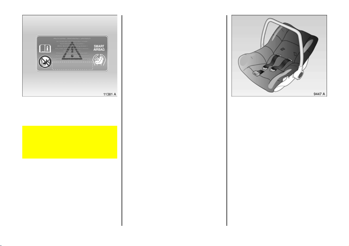
The seat occupa ncy recognition system
detects Vauxhall child re straint s ystems
with tra nsponders 3 and switches off the
front and side a irbag systems for the front
passenger's seat. The he ad airbag sy stem
remains activated. S eat occ upancy
recognition, see page 86.
Vauxhall child restraint systems with transponders 3 can be identified by the sticker
on the child restraint system.
Use of child restraint systems 3 on front
passenger seat in ve hicle s with airba g
systems 3 and with seat occupancy
recogniti on 3
Only Vauxhall child re straint systems
with transponders 3 can be fitted on the
front passenger seats. Use of systems
withou t transponders poses a danger to
li f e .
90
Child restraint systems 3
The Vauxhall c hild restraint system is
designe d spe cific ally for your Vauxhall an d
thus provides optimum safety for your child
in the even t of impact. If a different child
safety seat is used, follow the
manufacturers' instructions for fitting and
use.
Vaux hall safe ty cradle w ithout
tra nsponder
From birth up to a weight of 10 kg.
Page 93
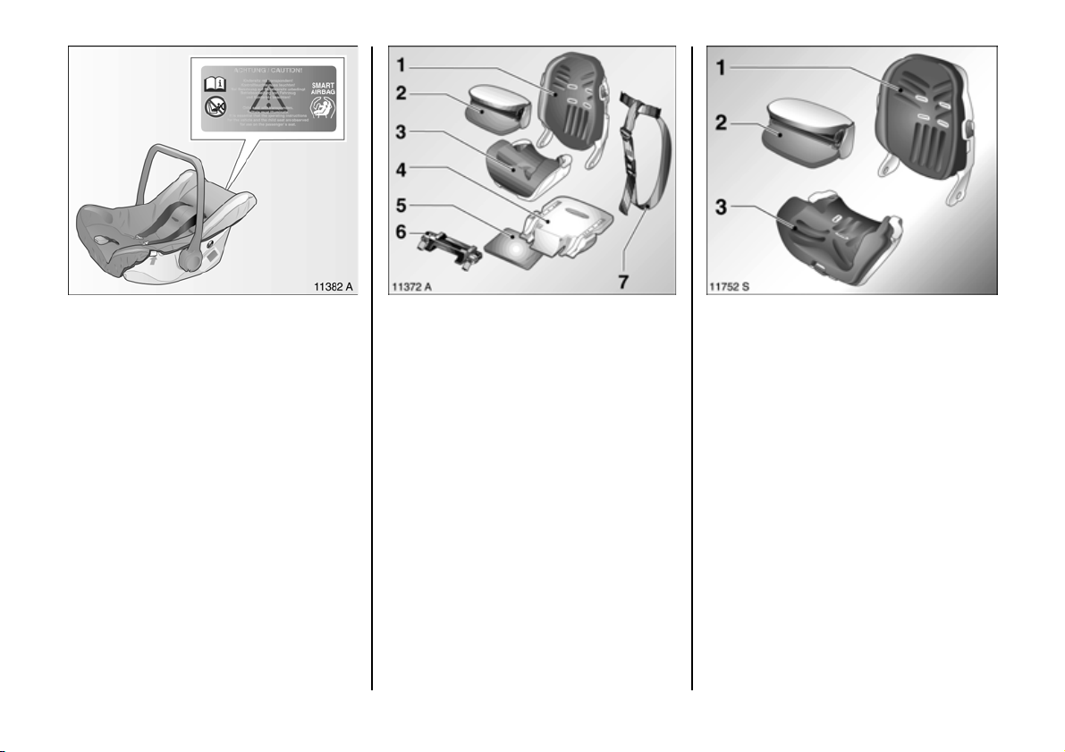
Vauxha ll sa fety crad le w ith transponders
From birth u p to a we ight o f 10 k g.
The trans ponders are integrated in the
seat cushion.
ISO-FIX child s afety se at
without t ransponders
From birth up to a weig ht of 36 kg.
Compris ing:
1 Se at bac kr est,
2 Safety support,
3 Se at cushion ,
4 Securing console,
5 He i gh t adju ste r cu shio n ,
6 Adapte r with belt buckles,
7 Reboard be lt.
Vaux hall chil d safe ty seat w ithout
tra nsponder
from body weight of 91) kg to 36 kg.
Comprising:
1 Seat backre st,
2 Safety supp ort,
3 Seat cu shion.
1)
Use of the system is not recommended for
ch il dr en w e ig hi n g l e ss t ha n 1 1 k g.
91
Page 94
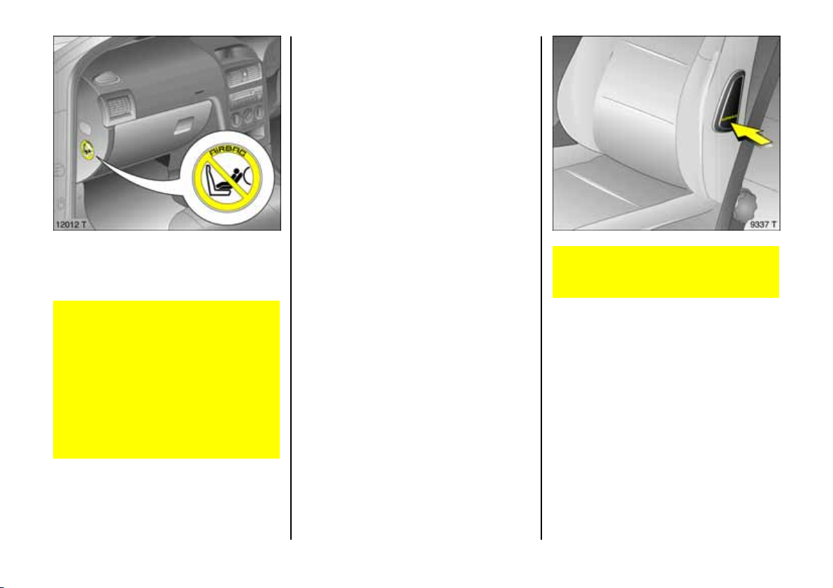
Vehicles with front pa ssenge r airbag ca n
be identified by the word AIRBAG above
the glove compartme nt and the warning
sti c ke r o n the side of t he in stru me nt p ane l ,
visible when the passenger door is open.
Use of child restraint systems 3 on front
passenger's se at in v ehi cles with air bag
systems 3 and without seat occupancy
recogniti on 3
Vehicles with front pas senger airbag 3
but without side airbag 3 : Rear-fac ing
child seats (safety cradle and safety
se a t s fo r w e igh t ran ges 0 an d I , see
following pag es) must not be fitted on
th e front p assenger seat; danger to life.
Forward-facing child seats (safety seats
for we ight ranges I, II and III, see
following pages) can be fitted on the
front pass enger seat provided that the
la tter is moved as far back as it will go.
92
Vehicles with side airbag 3: No child
restraint system 3 m ay be fitted on the
f ron t p a ss en ge r 's se a t ; r is k of fa ta l in j ury .
A v ehicle with side airbags can b e
identified by the word AIRBAG on the
outboard sides of the front seat backrests.
Seat occupancy recognition 3, s e e
pag e 86.
Page 95
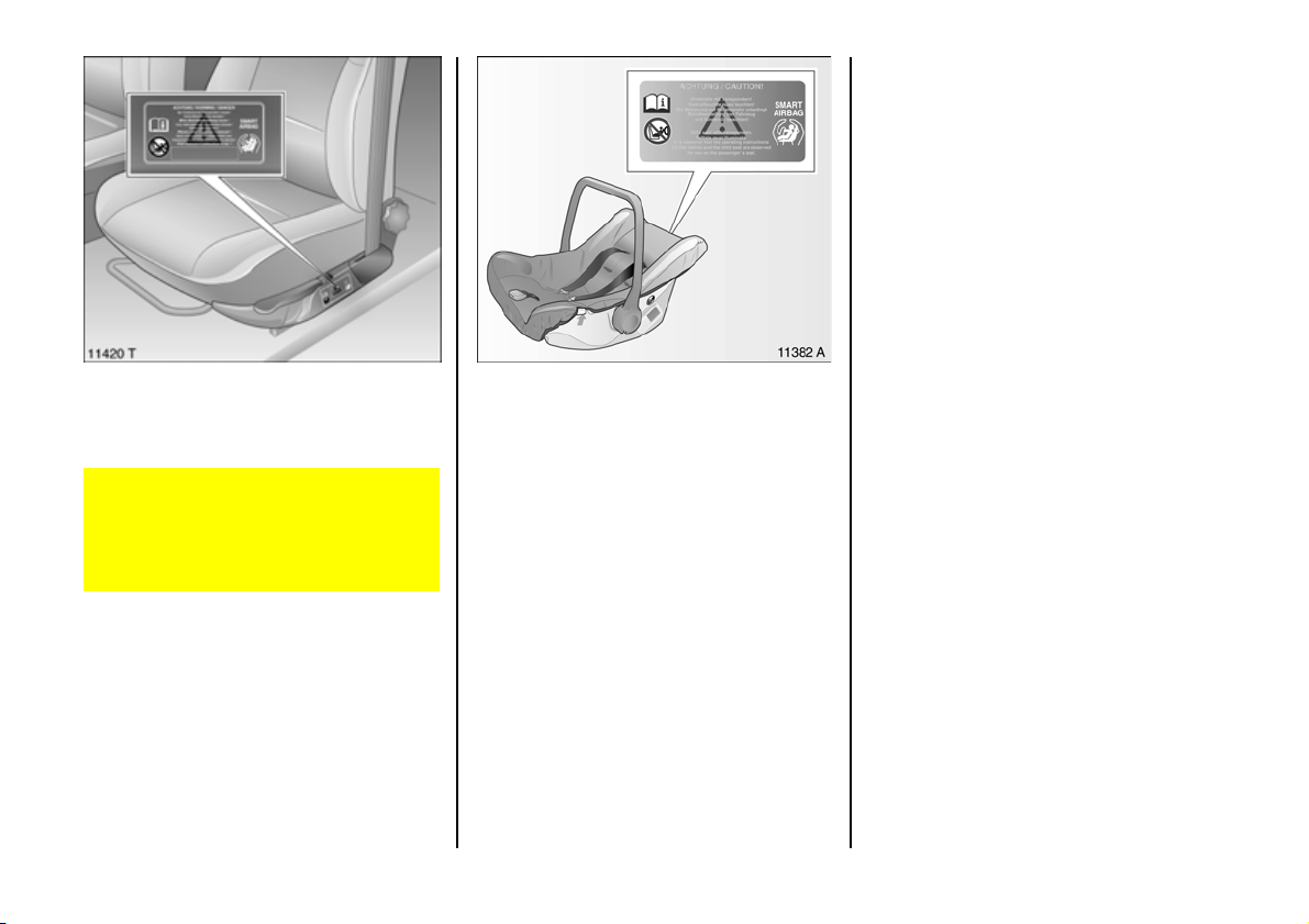
Use of child restraint systems 3 on front
passenger’s seat in vehicles with airbag
systems 3 and seat occupa ncy
recogniti on 3
Only Vauxhall child re straint systems
with transponders 3 can be fitted on the
front passenger’s seats. Use of systems
withou t transponders poses a danger to
li f e .
The se at occupancy recognition system
detects Vaux hall ch ild restrain t systems
with transponders 3 an d s wit ches off t h e
relevant airbag sy ste ms to protect the
child. Seat occ upancy recognition, see
page 8 6.
Vauxhall child restraint systems with
tra nsponders 3 can be iden t ified by the
sticker on the child restraint system.
Not e
z Children under 12 years or under 150 cm
tall should only trav el in an ap prop ria te
child safety sea t.
z When transporting children, use the child
restraint systems suitable for the child's
weight.
z Ensure that the child restraint system is
fitted correctly.
z The covers of the safety cra dle a nd
safety seat can be wiped clean.
z Do not stick anything on the child
restraint systems and do not cover them
with any other m aterials.
z Only allow the child to e nter and exit on
the s ide of the vehicle facing away from
the road.
z A child restraint system which has be en
subjected to stress in an accide nt must
be replaced.
z Yo u sh ou l d als o ob se rve the instruction s
on installation and use supplied with the
child restraint sy stem.
6
93
Page 96
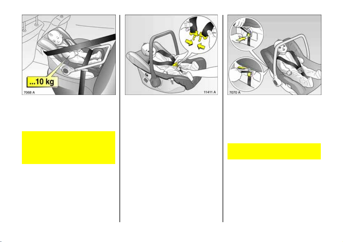
Ch ild rest rai nt sys tem ,
Vau xhall saf ety cradle 3 w i thou t
transponder
For babies ag ed up to 10 months or
we i g hi n g up t o 10 kg.
In vehicles with front passenger airba g 3
or side airbag 3, the safety cradle must
not be fitted on the front passenger's
seat, risk of fatal injury. In this case, fit
the safety cra dle on the rear seat.
94
Fas t e nin g t he chi ld' s sea t b el t
Plac e child in safety cradle .
Join the two shoulder be lts of the safety
cradle as shown in the illustration and
engage in belt buckle between the child's
legs.
Ad apting to the child's size
The length and height of the belts on the
safety cradle can be adjusted according to
the child's size:
To adjust length, p ull belt strap at rear of
safety cradle or loosen it by pre ssing the
metal clip.
The belt must fit snugly a cross the child's
body without being too tight.
Page 97
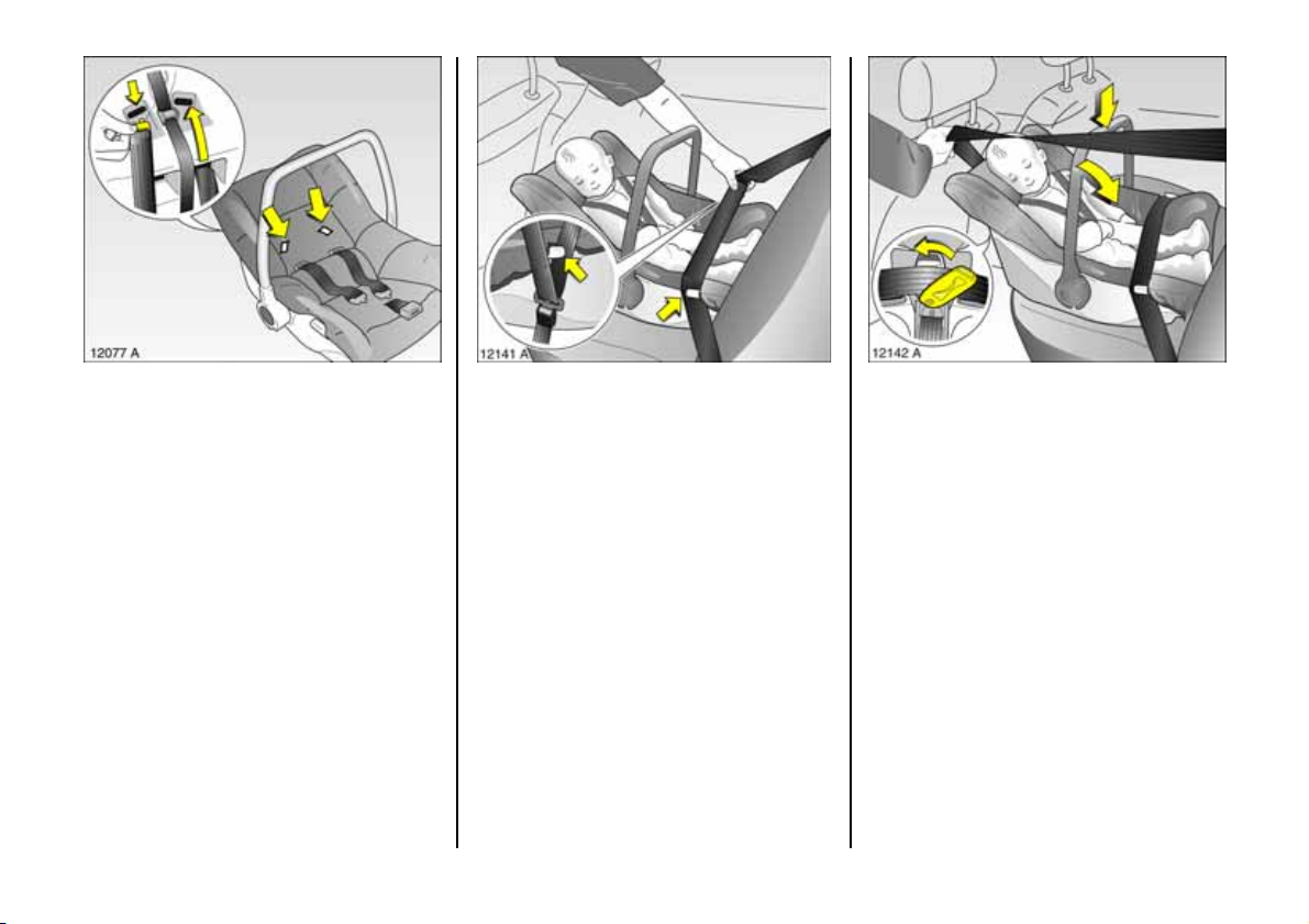
To adjust height, pull both shoulder belts
towards rear through slots . Then guide
belts through slots in required position.
Securing in the vehicle
Raise carrying handle of s afety cra dle.
Plac e safety cradle on rear seat, with
belted c hild facing away from the d irection
of trav el .
Pull vehicle seat belt out of retractor and
route lap be lt through the two guide clips
on the sid e b olsters of the safety cradle.
Fasten b elt buckle.
Open clip on rear of safety cradle to side .
Route the diagonal part of the vehicle seat
belt around the back of the safety cradle
backrest through the open clip. Tighten
vehicle seat belt and close clip.
To disengage carrying handle, press down
and swivel in direction of v ehicle se at
bac krest.
95
Page 98

Ch ild rest rai nt sys tem ,
Vau xhal l safety cradle with
transponders
For babies ag ed up to 10 months or
we i g hi n g up t o 10 kg.
The Vauxhall safety cradle with transponders 3 ca n be iden tif ied b y a stic k er on t h e
safety cradle, se e page 90 .
Do not fit a child restraint system on the
front pas sen ger seat i f the v eh i cl e is
equipped with front passenger airbag 3
or side airbags 3, bu t does not have s eat
occupancy recognition 3. Otherwise,
th ere is a risk of fatal injury.
96
3
In vehicles with front pass enger airbag 3
or side airb ag 3 a nd se at occu pancy
recognition 3, only Vauxhall child
restraint systems with transponders 3
may be fitted on the front pa ssenger
seat; using systems without
transponders poses a risk of fatal injury.
Seat occupancy recognition 3, s ee
page 86 .
Vauxhall child restraint systems with
tra nsponders 3 may a lso be fitted on the
rear seat.
Fas t e nin g t he chi ld' s sea t b el t
Plac e child in safety cradle .
Join the two shoulder belts of the safety
cradle as shown in illustration 11411 A and
engage in belt buck le be tween the child’s
legs.
Ad apting to the child's size
The length and height of the belts on the
safety cradle can be adjusted according to
the child's size:
To adjust length, p ull belt strap at rear of
safety cradle or loosen it by pre ssing the
metal clip.
The belt must fit snugly a cross the child's
body without being too tight.
Page 99
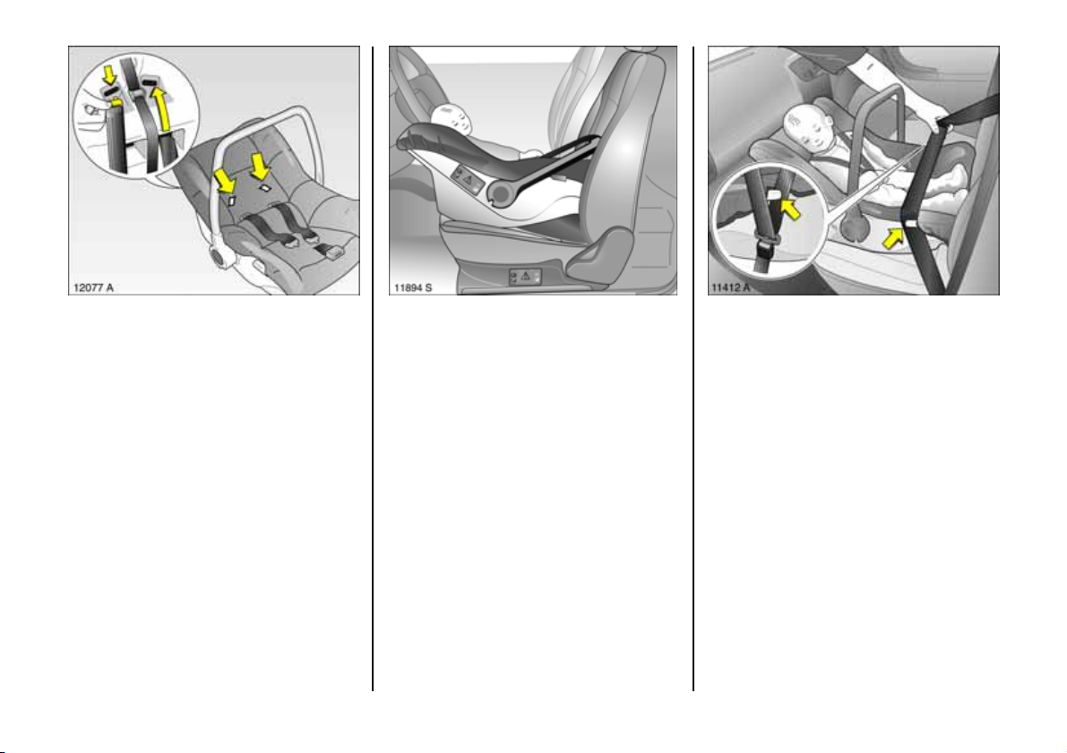
To adjust height, pull both shoulder belts
towards rear through slots . Then guide
belts through slots in required position.
Securing in the vehicle
Raise carrying handle of s afety cra dle.
Alw ays place child restraint cradle with
belt e d- i n c h ild on p a s se ng er s eat fa cing
away from the dire ction of travel.
Ad just seat backrest as described on
page 82 .
Move uppe r anchorage point of vehicle
seat belt to lowest position 3, see page 7 8.
Pull vehicle seat belt out of retractor and
route lap belt through the two guide clips
on the side bolste rs of the safety cradle.
Fasten belt buckle.
6
97
Page 100
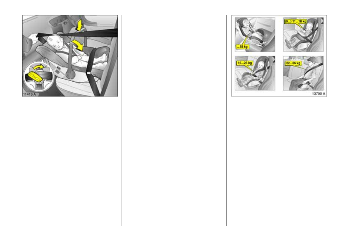
Child restraint systems,
ISO-FIX child safety seat
3
without transponders
Modula r system for va rious weight ranges:
z Weight range 0 and I: From birth up to a
weigh t of 18 kg. Only fit with child fac ing
away from direction of trav el.
z W eight class I: For weight of 9 kg to 18
kg; it is advisable only to use weight
class I for weig hts of 11 kg or more.
Always install facing direction of travel.
Open clip on rear of safety cradle to side.
Route the diagonal part of the vehicle seat
belt around the back of the safety cradle
backrest through the op en clip. Tig hten
vehic le seat belt and close clip.
To disengage c arrying ha ndle, press down
and swivel in direction of vehicle sea t
backrest.
98
z Weight class II: For we ight of 15 kg to
25 kg. Always install facing direction of
tra vel.
z Weight class III: For we ight of 22 kg to
36 kg. Always install facing direction of
tra vel.
 Loading...