

Onkyo TX-NR3030(B), TX-NR3030(S) Service Manual
TX-NR3030
Ref. No. 4478
102014
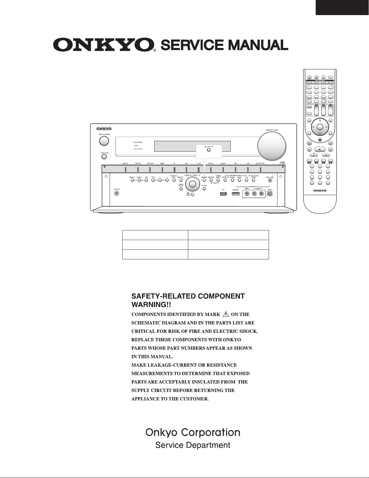
AV RECEIVER
MODEL TX-NR3030(B)/(S)
(European and
Asian models
Black and Silver models
B MDC
B MMP, S MMP
B MMR
120V AC, 60Hz
220-240V AC, 50/60Hz
220-240V AC, 50/60Hz
RECEIVER
SOURCE
ZONE
ALL OFF
MY MOVIE
MYTV
REMOTE MODE/INPUT SELECTOR
BD/DVD
STB/DVRCBL/ SAT
TV/CD
PC AUX
USBNET
TUNER
REMOTE MODE
MODE
RECEIVER
TV
CH
DISC
TV
VOL
ALBUM
INPUT
TOP MENU
GUIDE
ENTER
Q
SETUP RETURN
HOME
REPEAT RANDOM MODESEARCH
MOVIE/TV
MUSIC
GAME
123
456
789
1110 12
+
10
0
D.TUN
DIMMER DISPLAY
-
RC
884M
RC-884M
2RED
3GREEN
SLEEP
MY MUSIC
GAME
PHONO
BLUETOOTH
MUTING
VOL
MENU
PREV CH
PLAYLISTPLAYLIST
THX
CLR
TX-NR1030/3030/ PR-SC5530/ DTR-60.6/70.6/ DHC-80.6
DEBUG MODE-1
AUDIO DEBUG MODE-1/4
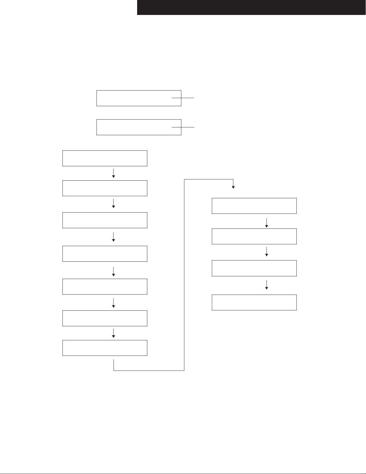
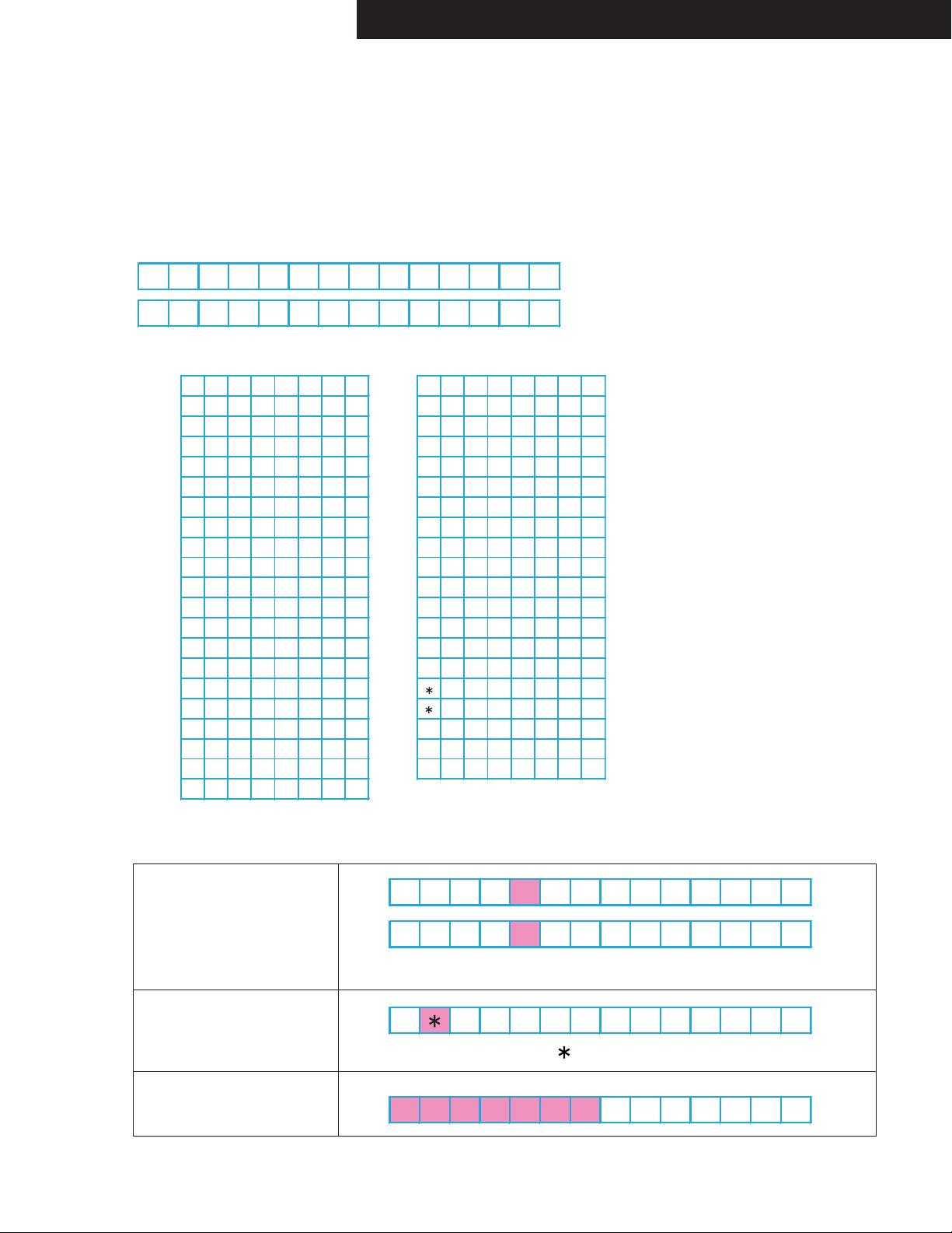
AUDIO DEBUG MODE (Display mode of the audio information)
The operations of DSP and DIR etc are able to checked by the information displayed on FL in this debug mode.
This information will help to analysing digital audio no sound trouble.
To set in Debug mode
1. Press twice the ON/STANDBY key while pressing the DISPLAY key.
2. Press +(TONE) button while the version number of microprocessor is displayed.
3. Press DISPLAY button while the version number of DSP is displayed.
e.g.
0A0002: :00
ANA:o:NON: :
4. Press DISPLAY button.
e.g.
1:ANA 048k048k
2/0.0: 2.0:3/4
5. Press DISPLAY button.
e.g.
2:o:PCM :PCM
00:x:F:OFF
6. Press DISPLAY button.
e.g.
SP00F*00F00409
48 48256STB
7. Press DISPLAY button.
e.g.
L : 0 0
R : 0 0
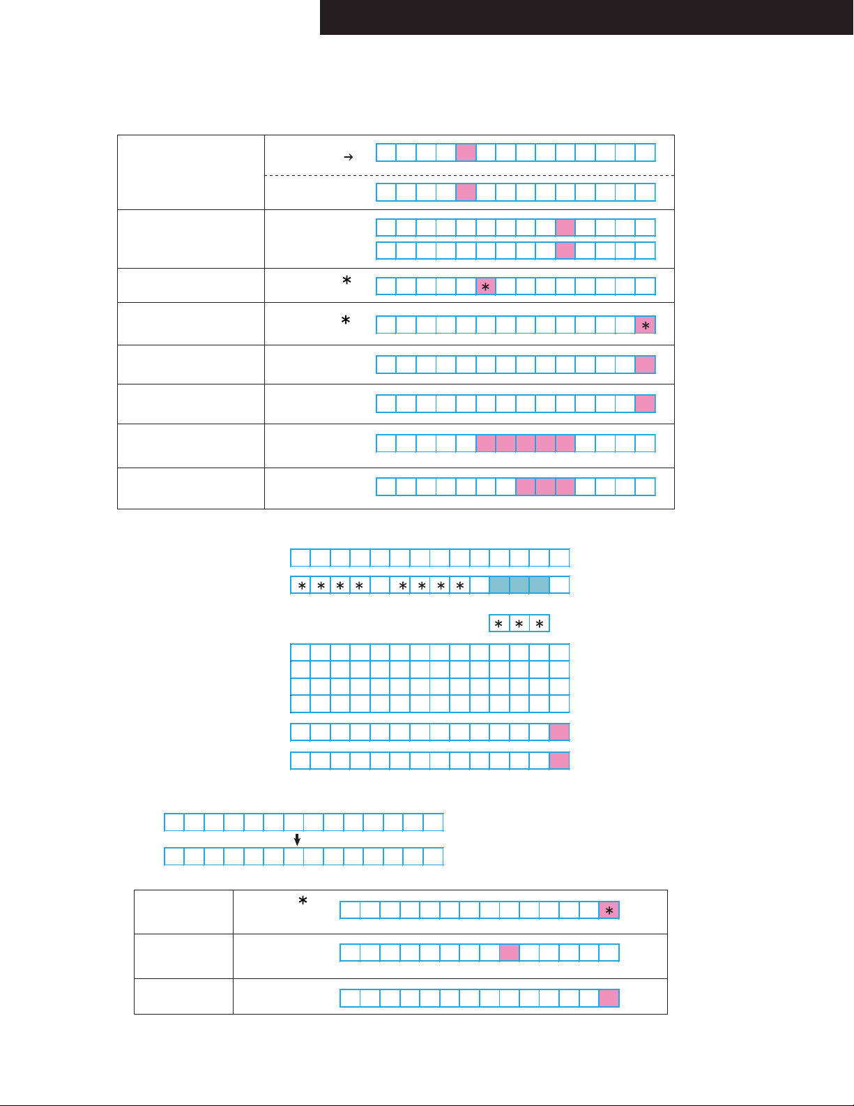
8. Press DISPLAY button.
e.g.
9. Press DISPLAY button.
e.g.
C : 0 0
LS : 0 0
RS : 0 0
e.g.
e.g.
Main:
1.01/13515AE8
DSP 1st/NET:
1.07/13514AEA
Audio dubug mode
Step-1
Step-2
Step-3
Step-4
Step-5
Step-6
Step-7
The version number of microprocessor is displayed
only for 3 seconds.
The version number of DSP is displayed
only for 3 seconds.
10. Press DISPLAY button.
e.g.
LB : 0 0
RB : 0 0
11. Press DISPLAY button.
e.g.
LH : 0 0
RH : 0 0
12. Press DISPLAY button.
e.g.
LW : 0 0
RW : 0 0
13. Press DISPLAY button.
e.g.
SW : 0 0
SW2 : 0 0
14. Press DISPLAY button.
Exit
Step-8
Step-9
Step-10
Step-11
DEBUG MODE-2
112233
:
AA
:
BB
CCC
:
D
:
EEE
:
F
:
G
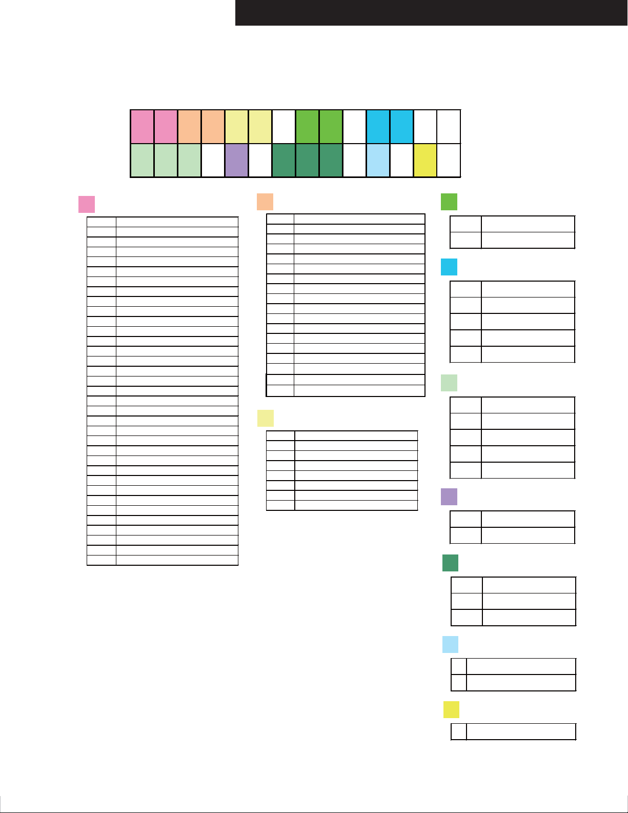
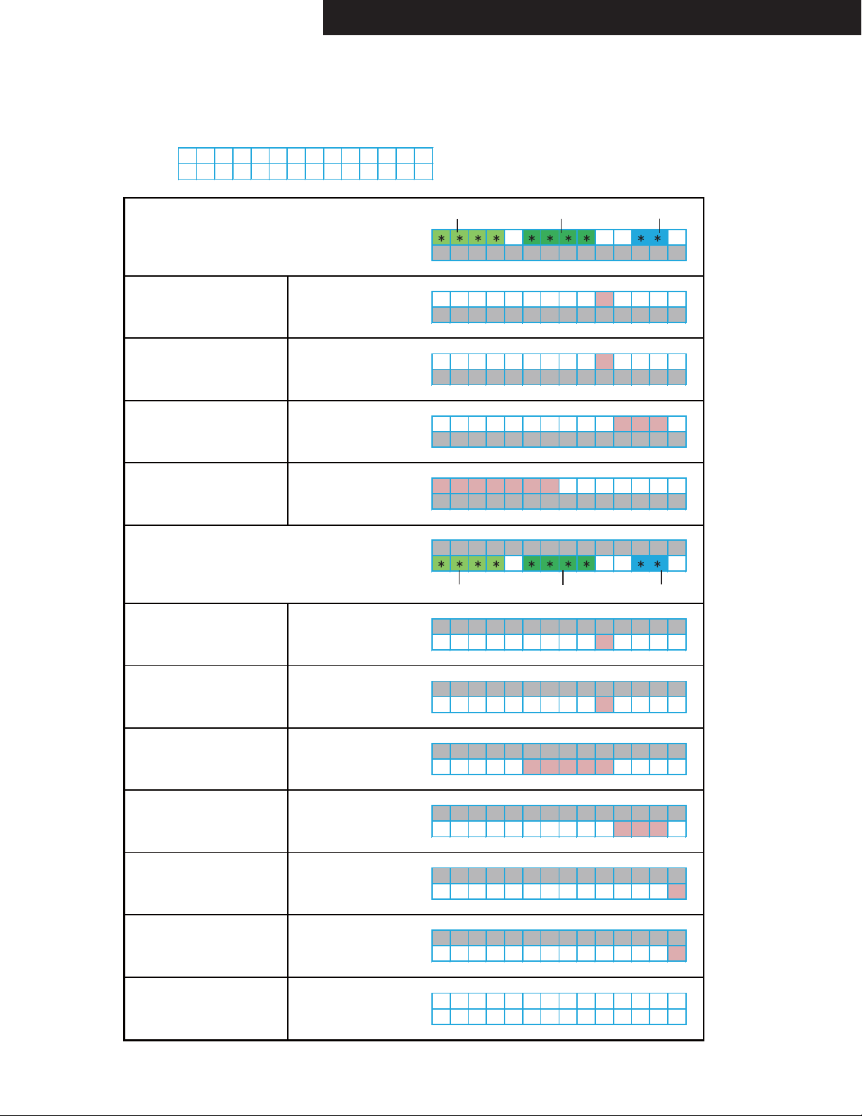
AUDIO DEBUG MODE-2/4
TX-NR1030/3030/ PR-SC5530/ DTR-60.6/70.6/ DHC-80.6
Step-1
1
st_srd.lmd
C_LM_LAST01
C_LM_PURE02
C_LM_DIRECT03
C_LM_STEREO04
C_LM_MONO05
C_LM_SURR20
C_LM_THX_MUSIC50
C_LM_THX_GAME70
C_LM_THX_CINEMA90
C_LM_THX_U2GAMEA0
C_LM_THX_U2MUSICA8
C_LM_THX_U2CINEMAB0
C_LM_AUDYSSEYD0
C_LM_DTSSS48
C_LM_ORCHESTRA06
C_LM_UNPLUGGED07
C_LM_STUDIOMIX08
C_LM_TVLOGIC09
C_LM_ALLCHST0A
C_LM_FULLMONO0B
C_LM_TD0C
C_LM_TESTTONEF1
C_LM_TESTTHRF2
C_LM_TESTAUTOF3
C_LM_ASCF4
C_LM_FLASHF5
C_LM_DEBUGMODEF6
C_LM_FLASH2F7
C_LM_FLASH3F8
C_LM_FLASH4F9
C_LM_FLASH_CHECKFA
C_LM_RPG0D
C_LM_ACTION0E
C_LM_ROCKBAND0F
C_LM_SPORTS10
FL Display
2
st_srd.extdec
C_EXTDEC_OFF00
C_EXTDEC_20_PLII01
C_EXTDEC_20_PLIIX02
C_EXTDEC_20_PLIIZ03
C_EXTDEC_20_NEO604
C_EXTDEC_51_MTR05
C_EXTDEC_51_DSC06
C_EXTDEC_51_NEO607
C_EXTDEC_51_EX08
C_EXTDEC_51_PLIIX09
C_EXTDEC_51_PLIIZ0A
C_EXTDEC_96240B
C_EXTDEC_9624_MTR0C
C_EXTDEC_71MULTI0E
C_EXTDEC_20_NEURAL0F
C_EXTDEC_51_NEURAL10
C_EXTDEC_DOLBY_20_SURR13
C_EXTDEC_DOLBY_51_SURR14
3
st_srd.extdecmd
C_EXTDECMD_OFF00
C_EXTDECMD_1001
C_EXTDECMD_2002
C_EXTDECMD_MOVIE03
C_EXTDECMD_MUSIC04
C_EXTDECMD_GAME05
C_EXTDECMD_HEIGHT06
C_EXTDECMD_WIDE07
A
Muting port
D
A
B
bit_1 SELMUTE
bit_2 POWMUTE
bit_3 PROTECTMUTE
bit_4 AUDIOOUTMUTE
bit_5 AUDIOMUTE
C
ANA Analog
COX Caxal
OPT Optical
HDM HDMI
ARC ARC
D
E
DIGMUTE port
AMUTE port
Factor of muting
Input
DSP Detect
○
DSP Detect OK
×
DSP No Detect
Sound state
STB SOUND STATE FIX
TRS SOUND STATE UNFIX
NON SOUND STATE NONE
F
Display inhibit
SCdisplay_inhibit SET
display_inhibit CLR
G
HDMI mute
V HDMI MUTE

DEBUG MODE-3
1: 1111222k333k
444. 5: 6666: 777
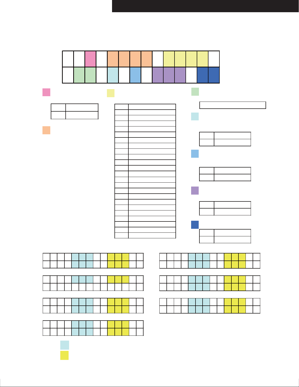
AUDIO DEBUG MODE-3/4
Step-2
1
Type of input format
source_format
UNLK
ANA
PCM
AC3
DTS
MPEG
DATA
UNKW
NORD
NPCM
FS96
NODT
DTSC
AAC
MPCM
MCH
TRUE
MSTR
DSD
PLUS
EXPR
DTSH
DDR_UNLOCK
DDR_ANALOG
DDR_PCM
DDR_AC3
DDR_DTS
DDR_MPEG
DDR_DATA
DDR_UNKNOWN
DDR_NOT_READY
DDR_NOT_PCM
DDR_FS96
DDR_NOT_DETECT
DDR_DTSCD
DDR_AAC
DDR_MCHPCM
DDR_MCH
DDR_TRUE
DDR_MSTR
DDR_DSD
DDR_DDPLUS
DDR_DTSEXP
DDR_DTSHD
TX-NR1030/3030/ PR-SC5530/ DTR-60.6/70.6/ DHC-80.6
2
Sampling frequency
st_srd.fs
3
Sampling frequency for display
st_hd_display.fs
??? unknown
008
011
012
016
022
024
032
044
048
064
088
096
176
192
8kHz
11kHz
12kHz
16kHz
22kHz
24kHz
32kHz
44.1kHz
48kHz
64Hz
88.2kHz
96kHz
176.4kHz
192kHz
4
Number of input channels
for listening mode transition
5
Input channel
st_srd.lfe, st_srd.lfe2
0
SW 0ch
1
SW 1ch
2
SW 2ch
7
Number of channels after
the decoding process
hd_dec_prgfmt
C_FMT_UNKNOWN
???
C_FMT_10
10
C_FMT_20
20
C_FMT_30
30
C_FMT_21
21
C_FMT_31
31
C_FMT_22
22
C_FMT_32
32
C_FMT_23
23
C_FMT_33
33
C_FMT_24
24
C_FMT_34
34
C_FMT_42H
4H2
5H2
C_FMT_52H
4W2
C_FMT_42W
5W2
C_FMT_52W
4H4
C_FMT_44H
4H3 C_FMT_43H
5H4 C_FMT_54H
5H3 C_FMT_53H
C_FMT_44W
4W4
4W3 C_FMT_43W
5W4 C_FMT_54W
5W3 C_FMT_53W
11 C_FMT_11
6
Number of channels for display
st_hd_display.prgfmt[4]
"10.2" "5.1" "1 +1" four-digit string
DEBUG MODE-4
2: 8: 9999:10101010
11 11 : 12 : 13 : 14 14 14 15 15
AUDIO DEBUG MODE-4/4
Step-3
8
Audio output OK?
f_dsp_detect_ok
o
Decode OK
x
Decode NG
9
Details of input format
st_srd.source
Step-5 to Step-11
TX-NR1030/3030/ PR-SC5530/ DTR-60.6/70.6/ DHC-80.6
11
10
Details of input format
st_hd_display.source
ANA
C_SRC_ANA
PCM
C_SRC_PCM
DLB
C_SRC_DD
DEX
C_SRC_DD_EX
DTS
C_SRC_DTS
MTR
C_SRC_DTS_MTR
DSC
C_SRC_DTS_DSC
D96
C_SRC_DTS_96
C_SRC_DTS_96M96M
AAC
C_SRC_AAC
MCH
C_SRC_MCH
DSP
C_SRC_DSP
C_SRC_MCHPCM
MPCM
DSD
C_SRC_DSD
TRUE
C_SRC_TRUE
TREX
C_SRC_TRUE_EX
C_SRC_MSTR
MSTR
C_SRC_DDPLUS
PLUS
C_SRC_DDPLUS_EX
PLEX
C_SRC_DTSEXP
EXP
DTSH
C_SRC_DTSHD
DSUR
C_SRC_DD_SUR
C_SRC_DDPLUS_SUR
DPSR
C_SRC_TRUE_SUR
TRSR
Dialog Norm
st_srd.dnorm
Dialog Norm value of 0 to 31
12 DIRINT
The return value of ddr
Request_dir (DDC_STATUS)
o
LOCK
k
UNLOCK
13 DIR busy or free
The return value of ddr Request_dir
(DDC_BUSY)
F Free
Busy
B
14
Emphasis information
f_dir_empha_mode
ON
OFF
15
HDDVD/BLUE(Only DDPLUS)
BD Bluray
HD HDDVD
ON
OFF
L:
R:
C:
:
LS :
RS :
LB :
RB :
The sum of the values of Volume correction related to the DSP.
The sum of the values of Volume correction, including correction
of the Analog stage.
LH :
RH :
LW :
RW :
SW :
SW2 :
TX-NR1030/3030/ PR-SC5530/ DTR-60.6/70.6/ DHC-80.6
1080 i / 60
→
1080 i / 60
480 I / 60
→
480P/ 60→
VGA →
Un k nown →
UNKNOWN
480 i / 60
480p/ 60
1080 i / 60
720p/ 60
1080p/ 60
240p/ 60
#480 i / 60
#480p/ 60
#240p/ 60
576 i / 50
576p/ 50
1080 i / 50
720p/ 50
1080p/ 50
288p/ 50
#576 i / 50
#576p/ 50
#288p/ 50
1080p/ 24
1080p/ 25
1080p/ 30
UNKNOWN
VGA
1080 i 100
720p100
576p100
576 i 100
1080 i 120
720p120
480p120
480 i 120
576p200
576 i 200
480p240
480 i 240
480p/ 60
576p/ 50
720p/ 24
720p/ 25
720p/ 30
DEBUG MODE-5
HDMI DEBUG MODE-1/4
HDMI-related operations can be checked to some extent by displaying HDMI debug mode.
To enter this mode
Hold down DISPLAY button for 3 seconds. Information display will last for about 8 seconds.
Resolution display method
The first line : Input resolution
The second line :Output resolution
List of standard resolution
Display of Input Resolution ---> The first line
DVI input signal
VGA input signal
No input
“I” and “P” will be capitalized.
Display the ” ” in column 1
TX-NR1030/3030/ PR-SC5530/ DTR-60.6/70.6/ DHC-80.6
1080p/ 24 ( 3D)
HDMI 4 4 4 3 6 b i t
1080p/ 24 ( 3D)
HDMI 4 4 4 # 3 6 b i t
1080p/ 24
(
3D)x
→1 0 8 0 i / 6 0
1080 i / 60
480 I / 60
480P/ 60
480p/ 60
480p/ 60#
480p/ 60x
-----
OFF
1080 i / 60→
xp/
3840x2160p/ 30
3840x2160p/ 25
3840x2160p/ 24
4096x2160p/ 24
3840x2160p/ 30x
3840x2160p/ 30#
DEBUG MODE-6
HDMI DEBUG MODE-2/4
Dislay of Output Resolution ---> The second line
For a video processor
Via VSP
Display the ” ”
in column 4
VSP skip
DVI input signal
VGA input signal
RSEN is OFF
EDID_READ is NG
Resolution Error
No output
(Signal output destination
can not be found.)
Hot-plug of Sink equipment
can not be detected.
4K Upscaling
Display of Input resolution
Display of Output resolution
List of resolution
i / p will be
capitalized.
Display the ” ”
in column 5
Display the ” ”
in column 14
Display the ” # ”
in column 14
Display the ” x ”
in column 14
480p/ 60
→
If the three-digit numbers
are refrate
Resolution Error
EDID_READ_NG
3D Display
RSEN OFF
EDID READ NG
Resolution Error
Display the ” ”
in column 14
Display the ” # ”
in column 9
Display the ” x ”
in column 13
The first line : Resolution display
The second line : Status Display

DEBUG MODE-7
HDMI DEBUG MODE-3/4
Status
Input Mode
HDMI input 1 0 8 0 p / 2 4 ( 3 D )
TX-NR1030/3030/ PR-SC5530/ DTR-60.6/70.6/ DHC-80.6
HDMI 4 4 4 3 6 b i t
Input Color
Deep Color
DVI Input 1 0 8 0 p / 2 4 ( 3 D )
No Input 1 0 8 0 p / 2 4 ( 3 D )
RGB 1 0 8 0 p / 2 4 ( 3 D )
422 1 0 8 0 p / 2 4 ( 3 D )
444 1 0 8 0 p / 2 4 ( 3 D )
24bit 1 0 8 0 p / 2 4 ( 3 D )
30bit 1 0 8 0 p / 2 4 ( 3 D )
36bit 1 0 8 0 p / 2 4 ( 3 D )
DVI 444 36 b i t
- - - 444 36b i t
HDMI RGB 3 6 b i t
HDMI 4 2 2 3 6 b i t
HDMI 4 4 4 3 6 b i t
HDMI RGB 2 6 b i t
HDMI RGB 3 0 b i t
HDMI RGB 3 6 b i t
3D format
Frame Packing F r a m e P a c k i n g
Field alternative F i e l d
Line alternative L i n e
Side-by-Side(Full) S i d e - b y - S i z e
L+depth L + d e p t h
L+depth + graphics L + d e p t h
S
ide by Side(Harf)
Top and Bottom T o p - a n d - B o t t o m
unknown U N K N O W N
INPUT/OUTPUT
Si de- by- Si ze
INPUT :
OU T PU T :
al ternat i ve
al ternat i ve
(Ful l )
+gr aph i c s
(Har f )
DEBUG MODE-8
HDMI DEBUG MODE-4/4
PC Resolution
1024x 768p/ 60→
1024x 768p/ 60
TX-NR1030/3030/ PR-SC5530/ DTR-60.6/70.6/ DHC-80.6
The first line : Input resolution
The second line :Output resolution
Display of Input resolution
DVI input
HDMI input
Display uppercase P/I
Display lowercase p/i
Three-digit numbers
are Referat
No input
Display of Output resolution
Horizontal resolution
1024x 768p/ 60
1024x 768P/ 60→
1024x 768p/ 60
1024x 768p/ 60→
1024x 768p/ 60
1024x 768P120→
1024x 768p/ 60
UNKNOWN
1024x 768p/ 60
1024x 768p/ 60→
Horizontal resolution
Vertical resolution
xp/→
xp/
Vertical resolution Referat
Referat
DVI output
HDMI output
Display”-----”
Three-digit numbers
are Referat
EDID READ NG
Resolution through
INPUT/ OUTPUT
Display uppercase P/I
Display lowercase p/i
Display the ” # ” in
column 13
Display the ” x ” in
column 13
1024x 768p/ 60→
1024x 768P/ 60
1024x 768p/ 60→
1024x 768p/ 60
1024x 768p/ 60→
→-----
1024x 768p/ 60→
1024x 768P120
1024x 768p/ 60→
1024x 768P/ 60#
1024x 768p/ 60→
1024x 768P/ 60x
IN : *
OU T : *

TX-NR1030/3030/ PR-SC5530/ DTR-60.6/70.6/ DHC-80.6
DEBUG MODE-9
SERVICE INFORMATION MODE
Displaying Service information
This service information display system is helpful in analyze the status when the unit goes into Protect mode and is powered off.
Pay attention that the status will change if a button is pushed.
1. Press twice the ON/ STANDBY key while pressing the DISPLAY key.
e.g.
1.01/13515AE8
2. Press HOME button within 3 seconds above.
e.g.
- 80 F 27 DD
The version of main microprocessor is
displayed only for 3 seconds.
Information Displayed (Record this Information)
Power off Cause
T : Thermal Protect
Temperature
: xx F or xx C
Volume Level
Listenning Mode
---> Refer to the code list below.
V : Voltage Protect
I : Current Protect
- : Other
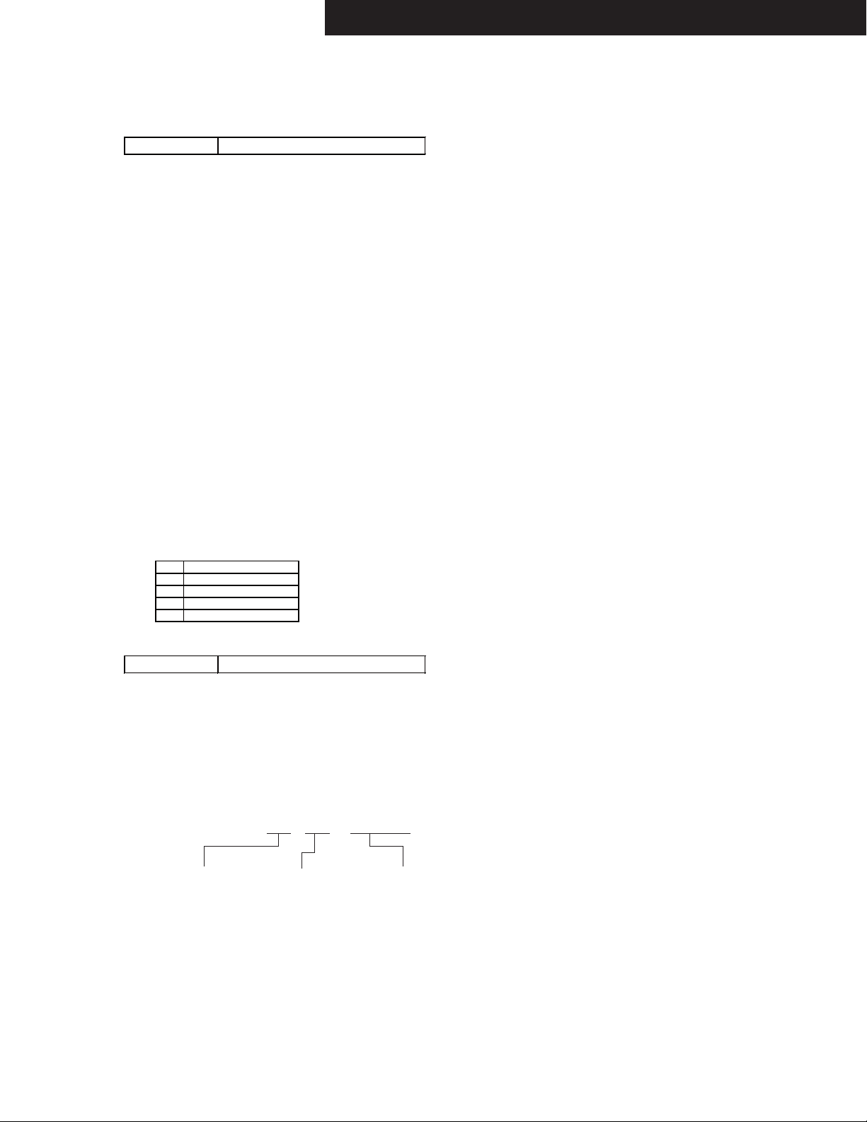
Listening Mode Code List
C_LM_LAST01
C_LM_PURE02
C_LM_DIRECT03
C_LM_STEREO04
C_LM_MONO05
C_LM_SURR20
C_LM_THX_MUSIC50
C_LM_THX_GAME70
C_LM_THX_CINEMA90
C_LM_THX_U2GAMEA0
C_LM_THX_U2MUSICA8
C_LM_THX_U2CINEMAB0
C_LM_AUDYSSEYD0
C_LM_DTSSS48
C_LM_ORCHESTRA06
C_LM_UNPLUGGED07
C_LM_STUDIOMIX08
C_LM_TVLOGIC09
C_LM_ALLCHST0A
C_LM_FULLMONO0B
C_LM_TD0C
C_LM_TESTTONEF1
C_LM_TESTTHRF2
C_LM_TESTAUTOF3
3. Press HOME button again. The following information are displayed.
e.g.
01:23 10h
Information Displayed (Record this Information)
C_LM_ASCF4
C_LM_FLASHF5
C_LM_DEBUGMODEF6
C_LM_FLASH2F7
C_LM_FLASH3F8
C_LM_FLASH4F9
C_LM_FLASH_CHECKFA
C_LM_RPG0D
C_LM_ACTION0E
C_LM_ROCKBAND0F
C_LM_SPORTS10
Time after Power on
xx : xx
Time after Initialize
xx hour
4. Press ON/STANDBY button to exit the display of service information.
(Ref.: Press RETURN button to initialize the data in the service information.)
ProtectData CLR
Normal display

TX-NR1030/3030/ PR-SC5530/ DTR-60.6/70.6/ DHC-80.6
OPERATION CHECK-1
NOTATION ABOUT ENTERING TEST MODE BY PRESSING BUTTON
In this procedure, the following notations are used to simplify explanation of how to press button.
e.g.-1 [TV/CD] + [ON/STANDBY] → [BD/DVD]
This means "While holding down TV/CD button, press ON/STANDBY button then release both buttons and then press
BD/DVD button".
e.g.-2 [DISPLAY] + [ON/STANDBY] *2 → [DIMMER]
This means "While holding down DISPLAY button, press ON/STANDBY button twice then release both buttons and then press
DIMMER button".
INITIAL SETTING FOR SHIPPING
Initialization of memories.
Do the following operation.
[CBL/SAT] + [ON/STANDBY]
Unplug the power cord from AVR after the FL tube displays "Clear" and AVR goes standby.
CONFIRMATION OF F/W VERSION
Do the following operation.
1. [DISPLAY] + [ON/STANDBY]
to display MMPU version.
e.g.
M1.03/14307ALN
2. [TONE+]
to display another F/W version.
e.g.
>ONKYO@
Main:
1.05/14X07AM
Main
>Integra@
Main:
1.05/14X07AM
Main
DSP 1st/NET:
1.03/14X08AMA
DSP 2nd
1.01/14930AMA
Video:
1.01/14X06AM
VSP(KYOTOG2H):
1.01/14910AEO
OSD(Sparta):
1.00/14219AM
Rogue(TX)
1.02/14730A
Rogue(RX)
1.01/14730A
DSP 1st/NET
DSP 2nd
HDMI/VIDEO
VSP
OSD
HDCP TX
HDCP RX
DSP 1st/NET:
1.03/14X08AMA
DSP 2nd
1.01/14930AMA
Video:
1.01/14X06AM
VSP(KYOTOG2H):
1.01/14910AEI
OSD(Sparta):
1.00/14219AM
Rogue(TX)
1.02/14730A
Rogue(RX)
1.01/14730A
VS100:
<NOTE>
It cannot enter a test mode immediately after power supply ON, please press the Setup key.
1.30.72.1
CONFIRMATION OF MAIN CHECKSUM
MAIN Checksum can be confirmed the following operation.
[DISPLAY] + [ON/STANDBY] * 2 → [MEMORY]
CONFIRMATION OF OUTPUT VOLTAGE AND THERMAL SENSOR
Temperature and output voltage can be confirmed the following operation.
[DISPLAY] + [ON/STANDBY] * 2 → [TONE]
DSP 1st/NET
DSP 2nd
HDMI/VIDEO
VSP
OSD
HDCP TX
HDCP RX
HDBase-T
e.g.
Voltage
of VOLH port
001 042 F:x S:H
Temperature
of thermal sensor
FAN speed
x: Stop
L: Low speed
H: High speed
Amplifier power
Supply voltage condition
H : High-B
L : Low-B
TX-NR1030/3030/ PR-SC5530/ DTR-60.6/70.6/ DHC-80.6
Model Name Distination Number Writing Data
TX-NR1030 Dx 2000 2000 TX-NR1030 Dx
NR1 0 3 0 D x 2 0 0 0
TX-NR1030 xx 8000 8000 TX-NR1030 xx
NR1 0 3 0 x x 8 0 0 0
TX-NR1030 JJ 4000 4000 TX-NR1030 JJ
NR1 0 3 0 J J 4 0 0 0
DTR-60.6 Dx 2060 2060 DTR-60.6 Dx
DTR60 6 Dx 206 0
DTR-60.6 xx 8060 8060 DTR-60.6 xx
DTR60 6 x x 806 0
DTR-60.6 JJ 4060 4060 DTR-60.6 JJ
DTR60 6 J J 406 0
TX-NR3030 Dx 2200 2200 TX-NR3030 Dx
NR3 0 3 0 D x 2 2 0 0
TX-NR3030 xx 8200 8200 TX-NR3030 xx
NR3 0 3 0 x x 8 2 0 0
TX-NR3030 JJ 4200 4200 TX-NR3030 JJ
NR3 0 3 0 J J 4 2 0 0
DTR-70.6 Dx 2260 2260 DTR-70.6 Dx
DTR70 6 Dx 226 0
DTR-70.6 xx 8260 8260 DTR-70.6 xx
DTR70 6 x x 826 0
PR-SC5530 Dx 2400 2400 PR-SC5530 Dx
SC5 530 Dx 2 4 0 0
PR-SC5530 xx 8400 8400 PR-SC5530 xx
SC5 530 x x 8 4 0 0
DHC-80.6 Dx 2460 2460 DHC-80.6 Dx
DHC8 0 6 Dx 2 4 6 0
DHC-80.6 xx 8460 8460 DHC-80.6 xx
DHC8 0 6 x x 8 4 6 0
DHC-80.6 JJ 4460 4460 DHC-80.6 JJ
DHC8 0 6 J J 4 4 6 0
FL Display
OPERATION CHECK-2
CONFIRMATION OF MODEL NAME AND DESTINATION
Model name and destination can be confirmed the following operation.
[TV/CD] + [ON/STANDBY] → [DIMMER](RT/PTY/TP) → [TONE+] *4
e.g.
N R 1 0 3 0 D x 2 0 0 0
FL DIS Name Destination A B C D
A:Value of AD port of BAND
B:Value of AD port of INIT1
C:Value of AD port of INIT2
D:Value of AD port of INIT3
TEST MODE FOR OPERATION
Do the following operation.
1. Set the following VOL level.
VOL level : 30
2. [TV/CD] + [ON/STANDBY]
TEST-_
3. Press the following button, while "TEST - " is displayed, then each test mode is set.
Button ButtonTest Mode Test Mode
[BD/DVD]
[CBL/SAT]
[STB/DVR]
In the test mode, (TONE)+ button is TEST MODE UP and (TONE)- button is TEST MODE DOWN.
1-00
2-00
3-00
e.g.
TEST 1-00 → TEST 1-01 → TEST 1-02 - - - - TEST 2-00
Button Test Mode
[GAME]
[PC]
[AUX]
IDLING TIMER (TEST 1-01)
This mode is used for aging for idling.
Once the following test mode is set, idling timer mode works.
Idling timer mode includes the following functions.
Test mode TEST 1-01
Function
WAV file L+Rch and Rch repetition (1sec each)
<NOTE> Store only one file (the above mentioned) into the USB flash device to avoid making trouble.
Once the above test mode is set, AVR's status changes to idling timer mode and voltage-detection protector check automatically begins.
If voltage-detection protector check is all OK, Wi-Fi connection check automatically begins.
Even if one channel of voltage-detection protector check is NG, Wi-Fi connection check doesn't begin.
Timer
Voltage-detection protector check
F/W update route test
Wi-Fi connection check
Z2 DAC route check by playing USB flash device
4-00
5-00
6-00
Refer to CONFIRMATION OF VOLTAGE-DETECTION PROTECTORS (next page).
Refer to CONFIRMATION OF UPDATE ROUTE (next page).
Refer to CONFIRMATION OF Wi-Fi CONNECTION (next page).
Refer to CONFIRMATION OF ZONE2 DAC ROUTE (next page).
[MEMORY]
[TUNING MODE]
[DIMMER](RT/PTY/TP)
[ENTER]
KEY TEST
IDLING TIMER / Wi-Fi check
FL TEST
FIRMWARE COMBINATION CHECK
TX-NR1030/3030/ PR-SC5530/ DTR-60.6/70.6/ DHC-80.6
1N/A
2VIDEO - OSD
3 DA830 - KG2H
4VIDEO - HDCP TX
5VIDEO - HDCP RX
OPERATION CHECK-3
CONFIRMATION OF VOLTAGE-DETECTION PROTECTORS.(The following model only)
Applied model TX-NR1030/3030, DTR-60.6/70.6
<NOTE>
Don't connect load nor short speaker terminals.
1. Do the following operation.
1-1. set the volume level to 30
1-2. [TV/CD] + [ON/STANDBY] → [BD/DVD]
1-3. [TONE +]
to the following test mode.
TEST 1-01
2. AVR automatically tests in the following test sequence. And if it is all OK, Wi-Fi test will begin.
Test sequence
(FL+)→(FR-)→(C+)→(SL-)→(SR+)→(SBL-)→(SBR+)→(FWL-)→(FWR+)→(FHL-)→(FHR+)
3. If FL tube displays Wi-Fi check mode then voltage-detection protectors test will be completed.
CONFIRMATION OF UPDATE ROUTE.
1. Do the following operation.
1-1. set the volume level to 30
1-2. [TV/CD] + [ON/STANDBY] → [BD/DVD]
1-3. [TONE +]
to the following test mode.
TEST 1-01
2. Once the above mentioned test mode is entered, voltage-detection protectors function is checked automatically first, then update
route check will begin.
If the result of update route check is no problem then Wi-Fi check will begin. If the result is NG then NG message will be shown on
the FL tube.
3. If FL tube displays Wi-Fi check mode then voltage-detection protectors test and update route check are passed.
Detail of NG number of F/W update route test is as below.
CONFIRMATION OF Wi-Fi CONNECTION (The following model only)
CONFIRMATION OF ZONE2 DAC ROUTE
Applied model TX-NR1030/3030,PR-SC5530
1. Setting Wi-Fi routers.
2. set the following test mode.
TEST 1-01
3. Once the above mentioned test mode is entered, voltage-detection protectors function is checked automatically first, then update
route check will begin and then Wi-Fi check will begin.
In Wi-Fi check mode, it connects an access point automatically. Wi-Fi LED flashes during connection.
4. If connection is completed and IP address is successfully acquired, Wi-Fi LED turning lights off and the value of RSSI to an access
point is displayed in dBm.
If the connection is failed, NG is displayed.
e.g.
02 -55d 01’ 14’’
RSSI(dbm)SSID No Time Counter
In case value of RSSI level isn't showed on the FL tube at all past 4 minutes in this timer mode, judge as NG.
If the connection is failed, exit the idling timer mode by pressing the TV/CD button and please try again from step-1.
1. Connect USB memory or USB storage to AVR front USB port.
2. set the following test mode.
TEST 1-01
3. After being displayed Wi-Fi RSSI level, it will play back wave file from USB storage.
(DTR60.6/DTR-70.6/DHC80.6) After update route check, it will play back wave file from USB storage.)
4. Check the wave form that appears L+R and R alternately from the following output terminal.
Output terminal :
ZONE2 PRE/LINE OUT
TX-NR1030/3030/ PR-SC5530/ DTR-60.6/70.6/ DHC-80.6
OPERATION CHECK-4
CONFIRMATION OF CURRENT DETECTION PROTECTORS (The following model only)
Applied model TX-NR1030/3030, DTR-60.6/70.6
1. Do the following operation.
1-1. set the volume level to 30
1-2. [TV/CD] + [ON/STANDBY] → [CBL/SAT]
1-3. [TONE - ]
to the following test mode.
TEST 1-09
2. Confirm that relay is not cut off even if you connect the following load A to the following channels one by one.
3. Confirm that relay is cut if you connect the following load B to the following channels one by one.
Channel FL, FR, C, SL, SR, SBL, SBR, LH, RH, LW ,RW ch
Load A 3 ohm
Load B 1 ohm
CONFIRMATION OF OUTPUT SENSOR
1. Do the following operation.
1-1. set the volume level to 30
1-2. [TV/CD] + [ON/STANDBY] → [CBL/SAT]
1-3. [TONE - ] *2 and (*3)
to the following test mode.
TEST 1-07 and TEST 1-08
After lighting "FM STEREO" on the FL tube.
Relays RL6901, RL6902, RL6903, RL6904
LW ,RW ch : TX-NR3030, DTR-70.6 only
CONFIRMATION OF COOLING FAN OPERATION
Applied model TX-NR1030/3030, DTR-60.6/70.6
1. Confirm fan that is not rotating.
2. Set the following test mode and confirm fan that is rotating at HIGH speed.
TEST 1-07
3. Set the following test mode B and confirm fan that is rotating at LOW speed.
TEST 1-08
CONFIRMATION OF KEY OPERATION
1. Do the following operation.
1-1. set the volume level to 30
1-2. [TV/CD] + [ON/STANDBY] → [CBL/SAT]
1-3. [TONE - ] *4
to the following test mode.
TEST 1-06
2. Confirm each key and master volume operation.
3. If "ON/STANDBY" button is pressed, AVR escapes from this KEY test mode.
Therefor, press the "ON/STANDBY" button, after checking other buttons finished.
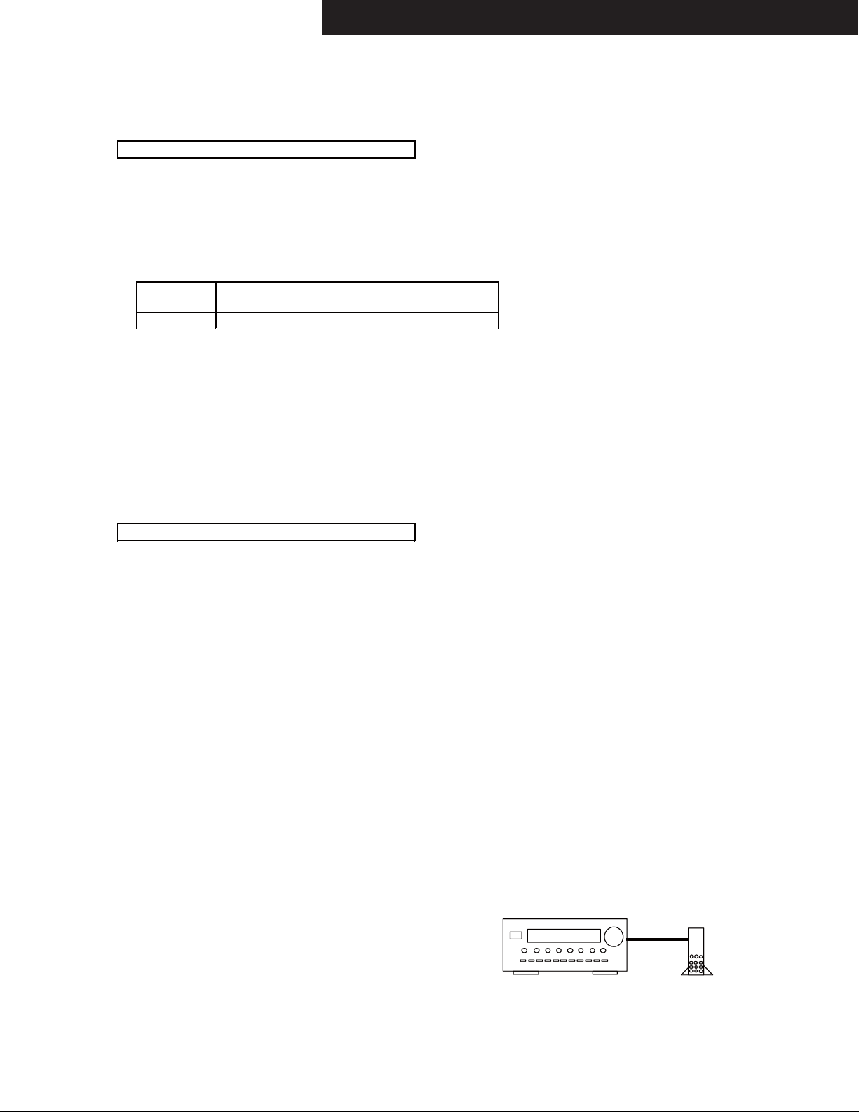
CONFIRMATION OF NETWORK
Please wait for about 1 minute after turning on the AVR when using the following test mode.
1. Connect the receiver to the router.
2. Do the following operation.
2-1. set the volume level to 30
2-2. [TV/CD] + [ON/STANDBY] → [CBL/SAT]
2-3. [TONE - ] *5
to the following test mode.
Connection
TEST 1-05
3. Confirm that the AVR's display shows appropriate IP address.
ETHERNET connector
Ethernet
cable
Router

TX-NR1030/3030/ PR-SC5530/ DTR-60.6/70.6/ DHC-80.6
OPERATION CHECK-5
CONFIRMATION OF FL TUBE AND LED
1. Do the following operation.
[TV/CD] + [ON/STANDBY] → [DIMMER]
2. Confirm that all LEDs and all segments of FL tube are lit.
CONFIRMATION OF HEAD PHONE OPERATION
Confirm the headphone mark when headphones plug is inserted into the PHONES jack.
CONFIRMATION OF FM RADIO OPERATION
1. Setting of Signal Generator(SG)
Carrier frequency any
Modulation 1kHz
Deviation 75kHz
Output level 35dBu
2. Waveform confirmation
Set the signal of SG as following channels and confirm output is the following table.
SG Input
(1) R ch only No Yes
(2) L + R ch Yes Yes
3. Confirmation of Stereo indicator
Set SG as stereo and confirm stereo indicator is on.
4. Confirmation of Auto stop operation
Do auto tuning (Press TUNING UP or TUNING DOWN button) and confirm that the searching stops when a station that
is set by SG is found.
Output
Lch R ch
CONFIRMATION OF RDS (RADIO DATA SYSTEM) OPERATION (Applied to MPP/MPB/MM* type )
1. Input 98MHz,30dBμ signal modulated with RDS data.
2. When a PS information is received, the name of the station "RDS TEST" shall be displayed within 2 seconds
instead of the frequency.
CONFIRMATION OF OSD(ON SCREEN DISPLAY) OPERATION
1. When HOME button is pushed, confirm that setup menu is displayed in HDMI Out.
2. Confirm that specified operations for ENTER(with 4-cursor) buttons are made.
CONFIRMATION OF CEC OPERATION
1. Connect AVR's HDMI OUT to HDMI input of appliance compatible with CEC(SINK or REPEATER) by HDMI cable.
2. Turn on the power to the AVR
3. Do the following operation.
3-1. set the volume level to 30
3-2. [TV/CD] + [ON/STANDBY] → [AUX]
to the following test mode.
TEST 6-00
FL tube will display "OK" or "NG".
CONFIRMATION OF DOLBY TEST TONE
1. Press TEST TONE on remote controller then press CH SELECT repeatedly.
Set turn to Dolby Test mode tone Check speaker condition.
2. Please check that a sound comes out from each channel.
-> FL ch -> C ch -> FR ch -> SR ch -> SBR ch -> SBL ch -> SL ch -> SW ch ->
TX-NR1030/3030/ PR-SC5530/ DTR-60.6/70.6/ DHC-80.6
OPERATION CHECK-6
CONFIRMATION OF VIDEO SIGNAL-DETECTION
1. Do the following operation.
1-1. set the volume level to 25(TX-NR636, DTR-30.6) or 30(TX-NR737, 838, DTR-40, 50.5).
1-2. [TV/CD] + [ON/STANDBY] → [PC]
1-3. [TONE +]
to the following test mode.
TEST 5-01
2. Confirm the following indicator lights up on the FL TUBE when the following video signal is input.
3. Furthermore, confirm the following indicator is turned off on the FL TUBE when the following video signal isn't input at the
following test mode as well.
(1) (2)
Input terminal
Indicator
Composite
FM STEREO
CONFIRMATION OF VIDEO IN/OUT
Confirm Video output signal as shown Table 2, while Video signal are input as shown Table 1 in "Video in_out" sheet.
<NOTE>Confirm the HDMI path at 1080p signal.
Table-1
Video Signal -> Composite Video
BD/DVD --- IN1 E IN1 G
CBL/SAT A IN2 F IN2 H
STB/DVR B --- --- IN3 I
GAME C --- --- IN4 J
--- --- --- --- IN5 K
--- --- --- --- IN6 L
--- --- --- --- IN7 ---
AUX D --- --- AUX M
Table-2
Output
Test mode
5-00(BD/DVD) --- --5-01(CBL/SAT) A A
5-02(STB/DVR) *B B
5-03(GAME) *C C
5-04(PC) --- --5-05(IN6) --- --5-06(IN7) --- --5-07(AUX) *D D
5-08(BD/DVD) --- --5-09(CBL/SAT) *A *A
Composite Video Component HDMI
Zone2 out
MONI TOR
OUT
Com pon ent HDMI
OUT Main/Sub/Zone2OUT
EG
FH
--- I
--- J
--- K
--- L
--- ---
--- --*E E
*F A
Component
RDS
CONFIRMATION OF FL DISPLAY
1. Do the following operation.
1-1. set the volume level to 30
1-2. [TV/CD] + [ON/STANDBY] → [DIMMER(RT/PTY/TP)]
to the FL test mode
[TONE+] = Step up
[TONE-] = Step down
The contents of the step
1. Lit all segment and LED
2. Lit '23456789ABCDEF' and LED.
3. Lit a even number segment
4. Lit an odd
5. The Destination setting is displaye
number segment and LED.
are as follows.
and LED.
d and LED..
OPERATION CHECK-7
TX-NR1030/3030/ PR-SC5530/ DTR-60.6/70.6/ DHC-80.6
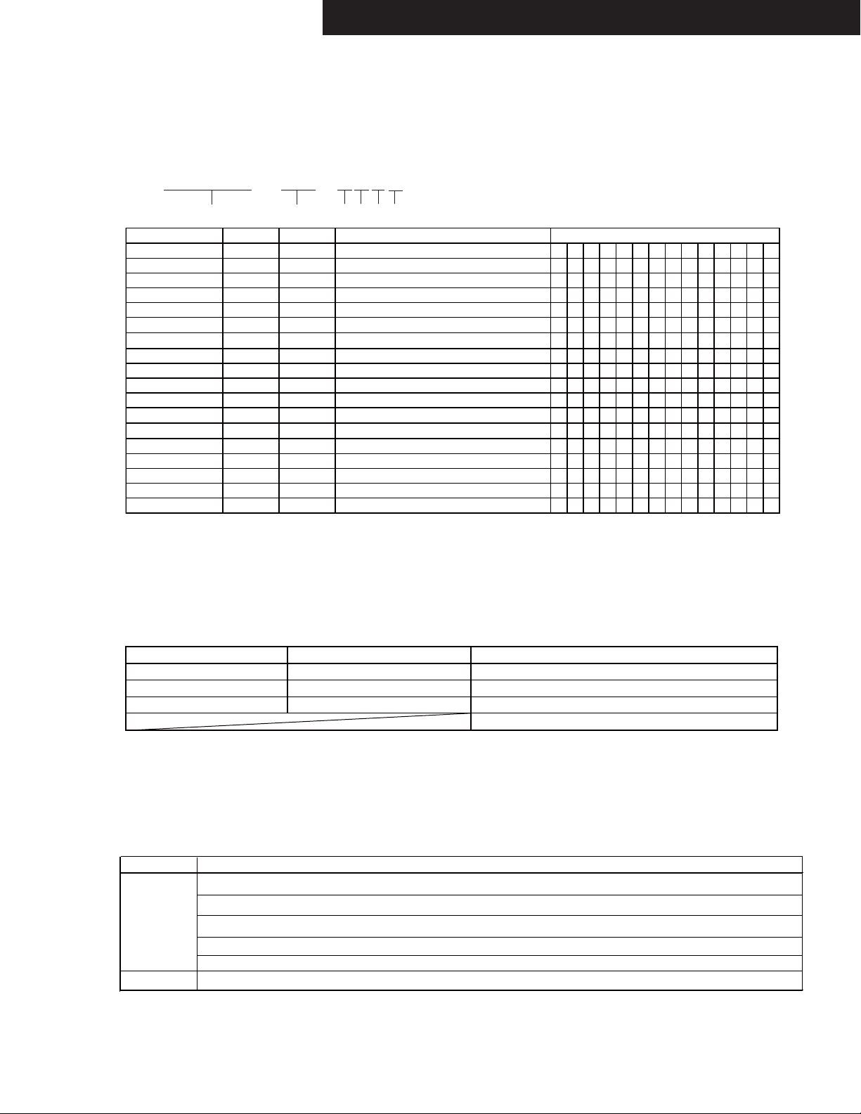
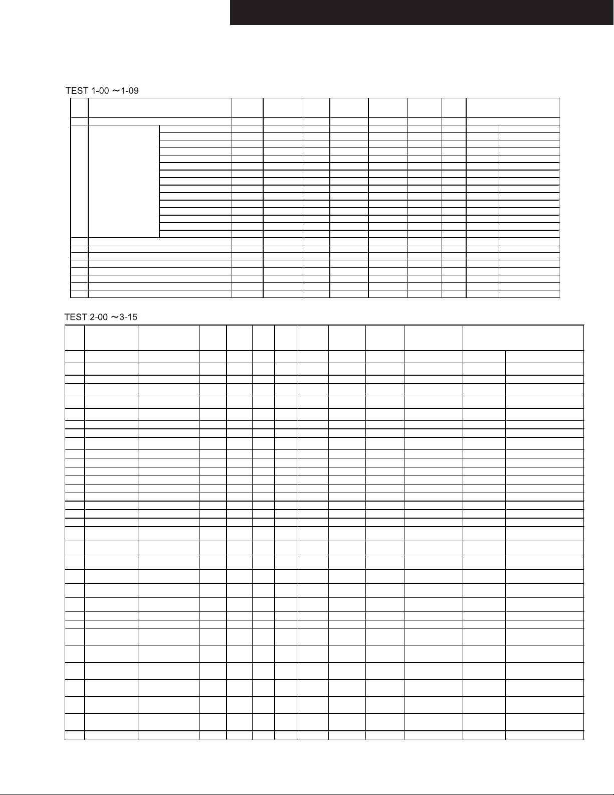
TEST DSP DS P DSP
No
1-00 SELECTOR MUTING TIME REDUCTION MODE - - - Y/L/L/L/L/L/L 82 (0dB) F - Analog Input Only
1-01 IDLING TIMER Timer start - - - Y/L/L/L/L/L/L Min (-82dB) F IDLING TIMER
1-02 MULTI TONE 1kHz + 30Hz + 20kHz , -20dBFS ALL
1-03 Wi-Fi check - - - Y/L/L/L/L Min (-82dB) F - Wi-Fi check
1-04 UPDATE ROUTE - - - Y/L/L/L/L Min (-82dB) - - UPDATE ROUT CHECK
1-05 DISPLAY IP ADDRESS - - - Y/L/L/L/L Min (-82dB) - - IP ADDRESS
1-06 KEY TEST - - - Y/L/L/L/L 76(-6dB) F/C/SB - *7 KEY TEST
1-07 VOLH DET / FAN HIGH-SPEED / 12V TRIGGER C
1-08 VOLH DET / FAN LOW-SPEED / 12V TRIGGER B (ZONE3)
1-09 CURRENT PROTECT / 12V TRIGGER A (ZONE2) ALL Pulse Max
V Protect (FL) FL +DC +Max
V Protect (FR) FR -DC -Max
V Protect (C) C +DC +Max
V Protect (SL) SL -DC -Max
V Protect (SR) SR +DC +Max
V Pro tect (SBL ) S BL -DC -Ma x
V Pro tect (SBR) SBR +DC +Ma x
V Protect (FHL) FHL - DC -Max
V Protect (FHR) FHR +DC +Max
V Protect (FWL) FWL -DC -Max
V Protect (FWR) FWR +DC +Max
UPDATE ROUTE - - - Y/L/L/L/L Min (-82dB) F - UPDATE ROUT CHECK
Wi-Fi check - - - Y/L/L/L/L Min (-82dB) F - Wi-Fi check
Z2 DAC (USB Play) - - - Y/L/L/L/L Min (-82dB) F - Z2 PREOUT Z2 DAC (USB Play)
Outp ut
ch
F,C,S,SB,H
W,C,S,SB,H
Outp ut
Frequency
1kHz+30Hz+20kHz
1kHz 0dBFS
1kHz 0dBFS
Output
Voltage
-20dBFS
TEST Analog Input Listening Mode/ VIDEO Compo- HDMI 12V Digital Input
No [Rec Sel] Input Format Input nent V TRG /Output Zone2/3 Vol. Relay
(Zone2/Zone3)
2-00 BD/DVD (Off) Analog All Ch Stereo BD/DVD IN1 - - - - Max (+18dB)
2-01 BD/DVD (Off) ADC DSP 13ch Thru. BD/DVD IN1 - - -
2-02 BD/DVD (Off) ADC DSP 13ch Thru. BD/DVD IN1 - - -
2-03 CBL/SAT (Off) DIR DSP 13ch Thru CBL/SAT - - - *OPT1
2-04 MIC ADC DSP 13ch Thru. BD/DVD BD/DVD - - -
2-05 MIC ADC DSP 13ch Thru. BD/DVD BD/DVD - - -
2-06 PHONO/Source Direct BD/DVD - - - - - Max (+18dB) F
2-07 BD/Source Bi AMP BD/DVD IN1 - - - - Max (+18dB) F/C/S/FH
2-08
BD/Source
ADC DSP 13ch Thru.
BD/DVD IN1
-
- - Y/L/L/L/L/L/L Max (+18dB)
2-09 BD/Source ADC DSP 5ch Thru. BD/DVD IN1 - - - Y/L/L/L Max (+18dB) F/C/S
2-10
BD䠄BALANCE䠅 Direct BD/DVD IN1
-
- - Y/L/L/L/L/L/L Max (+18dB) F/CS/SB/H/W
2-11 BD䠄BALANCE䠅 ADC DSP 13ch Thru. BD/DVD IN1 - - - Y/L/L/L/L/L/L Max (+18dB) F/CS/SB/H/W
2-12 BD/DVD (Off) ADC DSP 13ch Thru. BD/DVD IN1 - - - Y/L/L/L/L Max (+18dB) CS/SB SPRLF OFF
2-13 BD/DVD (Off) Stereo(Direct) BD/DVD IN1 - - - - Max (+18dB) F SW=NO
2-14 PHONO/Source Direct BD/DVD - - - - - 62(-20dB) F
Con fig.
SW/F/C/S/SB
/H/W
Y/L/L/L/L/L/ L
Y/L/L/L/L/L/ L
Y/L/L/L/L/L/ L
Y/L/L/L/L/L/ L
Y/L/L/L/L/L/ L
Y/L/L/L/L/L/ L
Y/L/L/L/L/L/ L
Y/L/L/L/L/L/ L
Y/L/L/L/L/L/ L
Y/L/L/L/L/L/ L
Y/L/L/L/L/L/ L
Y/L/L/L/L/L/ L
Y/L/L/L/L/L/ L
Y/L/L/L/L/L/ L
Y/L/L/L/L/L/ L
Config.
Y/L/L/L/L/L/L
Y/L/L/L/L/L/L
Y/L/L/L/L/L/L
Y/L/L/L/L/L/L
Y/L/L/L/L/L/L
Master Vol.
/Zone2 Vol. Relay TRG
Max (+18dB)
Max (+18dB)
Max (+18dB)
Max (+18dB)
Max (+18dB)
Max (+18dB)
Max (+18dB)
Max (+18dB)
Max (+18dB)
Max (+18dB)
Max (+18dB)
82 (0dB)
84 (+2dB)
84 (+2dB)
78(-4dB)
Speaker
F/CS/SB/H/W
F/CS/SB/H/W
F/CS/SB/H/W
F/CS/SB/H/W
F/CS/SB/H/W
F/CS/SB/H/W
F/CS/SB/H/W
F/CS/SB/H/W
F/CS/SB/H/W
F/CS/SB/H/W
F/CS/SB/H/W
F/CS/SB/H/W
F/CS/SB/H/W
F/CS/SB/H/W
F/CS/SB/H/W
12V etc.
- *1, *3 +DC Protect
- *1, *3 -DC Protect
- *1, *3 +DC Protect
- *1, *3 -DC Protect
- *1, *3 +DC Protect
- *1, *3 -DC Protect
- *1, *3 +DC Protect
- *1, *3 -DC Protect
- *1, *3 +DC Protect
- *1, *3 -DC Protect
- *1, *3 +DC Protect
- *6 Multi tone
C*5 VOLH DET䚸FAN High
B (Z3) *5 VOLH DET䚸FAN Low
A (Z2) *1, *4 Current Protect
Master Vol. Speaker etc.
F/CS/SB/H/W(11ch model䠅
F/CS/SB/H(9ch model㸧
82 (0dB)
Min (-82dB)
Max (+18dB)
Max (+18dB)
Max (+18dB)
F/CS/SB/H/W(11ch model䠅
F/CS/SB/H(9ch model䠅
F/CS/SB/H/W(11ch model䠅
F/CS/SB/H(9ch model䠅
F/CS/SB/H/W(11ch model䠅
F/CS/SB/H(9ch model䠅
F/CS/SB/H/W(11ch model䠅
F/CS/SB/H(9ch model䠅
F/CS/SB/H/W(11ch model䠅
F/CS/SB/H(9ch model䠅
F/CS/SB/H/W(11ch model䠅
F/CS/SB/H(9ch model䠅
AMUT OFF
MICMUTE ON
LINE GAIN,HUM NOISE
ADC GAIN etc.
MIN NOISE
DAC HUM NOISE
MIC GAIN
MIC MUTING
PHONO GAIN etc.
Bi AMP
HUM NOISE
DIFF SIG MODE
BALANCE
BALANCE:MONO
PREOUT RELAY OFF
HP GAIN/SP-B GAIN
PHONO SEP.
2-15 BD/DVD (Off) Analog All Ch Stereo BD/DVD IN1 - - - Y/L/L/L/L/L/L Max (+18dB) F/CS/SB/W HighAMP->Widech path
2-16 BD/DVD (Off) Analog All Ch Stereo BD/DVD IN1 - - - Y/L/L/L/L/L/L Max (+18dB) F/CS/H/W SBAMP->Widech path
3-00 FM/Source Stereo(Direct) BD/DVD BD/DVD - - - - 84(+2dB) F
3-01 GAME(BD/TV) Stereo(Direct) BD/DVD BD/DVD - - - - Max (max) F/Z2/Z3
3-02 GAME(BD/TV) Stereo(Direct) BD/DVD BD/DVD - - - - Max (max) F/Z2/Z3
3-03 GAME(BD/TV) Stereo(Direct) BD/DVD BD/DVD - - - - Max (max) F/Z2/Z3
3-04 GAME(BD/TV) Stereo(Direct) BD/DVD BD/DVD - - - - Max (max) F/Z2/Z3
3-05 GAME(BD/TV) Stereo(Direct) BD/DVD BD/DVD - - - - Max (max) F/Z2/Z3
3-06 GAME(BD/TV) Stereo(Direct) BD/DVD BD/DVD - - - - Max(max) F/Z2/Z3
3-07 GAME(BD/TV) Stereo(Direct) BD/DVD - - - - - Min (-82dB) F/Z2/Z3
LINE/PRE:PRE
Z2MUTE ON
LINE/PRE:PRE
Powered:ON
LINE/PRE:PRE
Powered:ON
LINE/PRE:PRE
Powered:ON
LINE/PRE:PRE
Powered:ON
LINE/PRE:PRE
Powered:ON䚸
Z2/Z3Vol=82
Powered:ON䚸
Z2/Z3Vol=82
Z2/Z3Vol=82
Z2 Bass=Max
Z2/Z3Vol=82
Z2 Bass=Min
Z2/Z3Vol=82
Z2 Treble=Max
Z2/Z3Vol=82
Z2 Treble=Min
Z2/Z3PRE VOL MAX ATT
3-08 GAME(BD/TV) Stereo(Direct) BD/DVD - - - - - Max (FIX) F/Z2/Z3 Z2/Z3 LINEOUT (Mid)
3-09 USB/(Source) Stereo(Direct) Last - - - Front USB - Min (-20dB)
3-10 USB/(Source) Stereo(Direct) Last - - - Front USB - Min (-20dB)
3-11 USB/(Source) Stereo(Direct) Last - - - Front USB - Min (-20dB)
3-12 USB/(Source) Stereo(Direct) Last - - - Front USB - Min (-20dB)
3-13 USB/(Source) Stereo(Direct) Last - - - Front USB - Min (-20dB)
3-14 USB/(Source) Stereo(Direct) Last - - - Front USB - Min (-20dB)
F
F
F
F
F
F
3-15 USB/(Source) DSD DAC Direct Last - - 51 F/C/S
Z2 out
Z2 out
Z2 out
Z2 out
Z2 out
Z2 out
- DSD(NET) DAC Direct check
1.44.1kHz_16bit_1kHz_0
dBfs_L&R.wav *2
2.44.1kHz_16bit_-∞
dBfs_L&R.wav *2
3.44.1kHz_16bit_20Hz_0
dBfs_L&R.wav *2
4.44.1kHz_16bit_20kHz_
0dBfs_L&R.wav *2
5.44.1kHz_16bit_1kHz_0
dBfs_Lch.wav *2
6.44.1kHz_16bit_1kHz_0
dBfs_Rch.wav *2
TX-NR1030/3030/ PR-SC5530/ DTR-60.6/70.6/ DHC-80.6
OPERATION CHECK-8
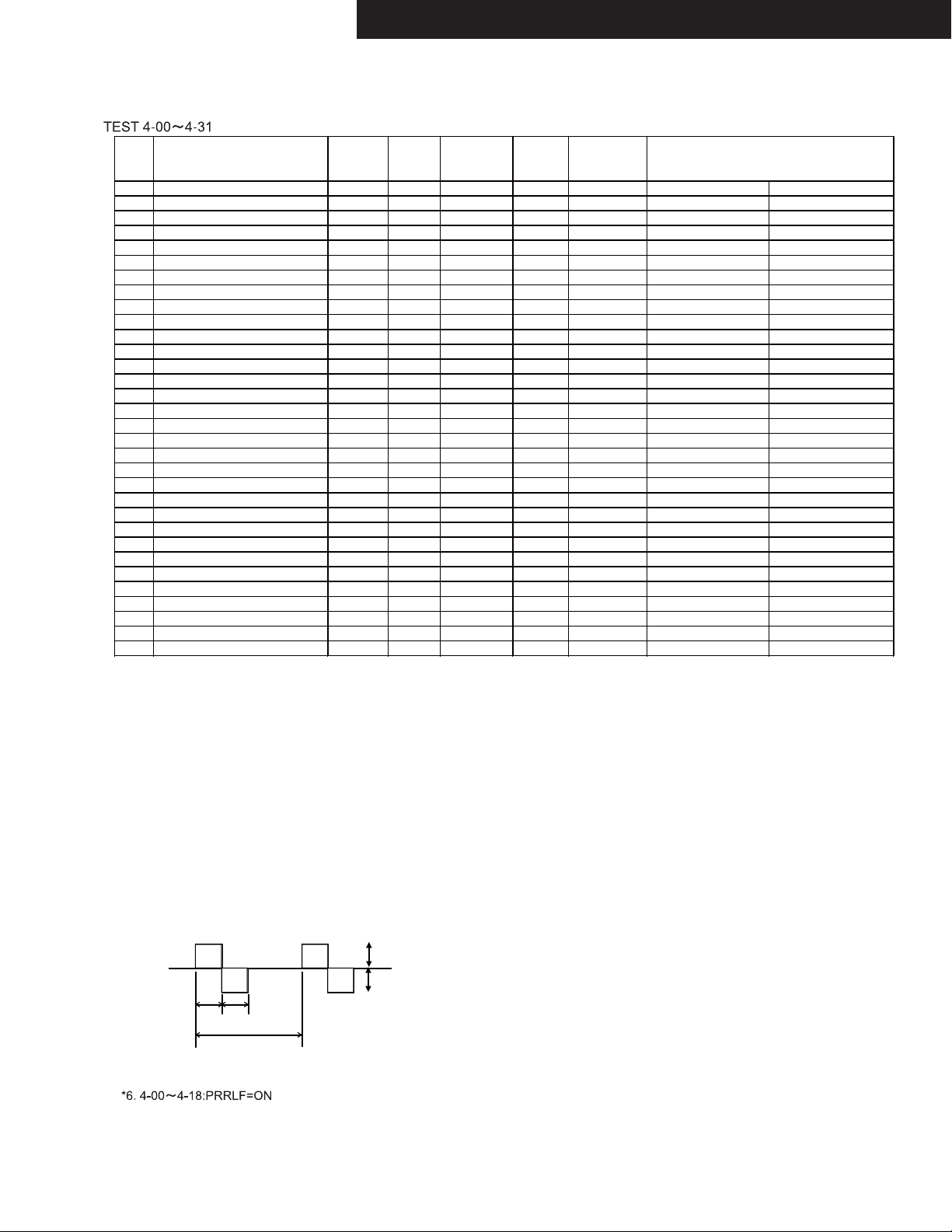
Auto Measurement Mode
DSP Output channel DSP
No. Output
Frequency
4-00 ALL
4-01 ALL
1kHz (SW㻦30Hz)
30Hz (SW㻦1kHz)
4-02 ALL 20kHz -20dBFS Y/L/L/L/L/L/L 82 (0dB) F/CS/SB/H/W *6 DSP Freq.Response
4-03 SW 30Hz -20dBFS Y/L/L/L/L/L/L 72(-10dB) F/CS/SB/H/W *6 Characteristic(1)
4-04 FL,FR 30Hz -20dBFS Y/L/L/L/L/L/L 82 (0dB) F/CS/SB/H/W *6 Characteristic(2)
4-05 ALL
4-06 ALL
1kHz (SW㻦30Hz)
1kHz (SW㻦30Hz)
4-07 FR,C,SUR,SURB,HIGH,WIDE,SW 10kHz -20dBFS Y/L/L/L/L/L/L 82 (0dB) F/CS/SB/H/W Mute:FL *6 Separation(FL)
4-08 FL,C,SUR,SURB,HIGH,WIDE,SW 10kHz -20dBFS Y/L/L/L/L/L/L 82 (0dB) F/CS/SB/H/W Mute:FR *6 Separation(FR)
4-09 F,SUR,SURB,HIGH,WIDE,SW 10kHz -20dBFS Y/L/L/L/L/L/L 82 (0dB) F/CS/SB/H/W Mute:C *6 Separation(C)
4-10 F,C,SR,SURB,HIGH,WIDE,SW 10kHz -20dBFS Y/L/L/L/L/L/L 82 (0dB) F/CS/SB/H/W Mute:SL *6 Separation(SL)
4-11 F,C,SL,SURB,HIGH,WIDE,SW 10kHz -20dBFS Y/L/L/L/L/L/L 82 (0dB) F/CS/SB/H/W Mute:SR *6 Separation(SR)
4-12 F,C,SUR,SBR,HIGH,WIDE,SW 10kHz -20dBFS Y/L/L/L/L/L/L 82 (0dB) F/CS/SB/H/W Mute:SBL *6 Separation(SBL)
4-13 F,C,SUR,SBL,HIGH,WIDE,SW 10kHz -20dBFS Y/L/L/L/L/L/L 82 (0dB) F/CS/SB/H/W Mute:SBR *6 Separation(SBR)
4-14 F,C,SUR,SURB,HIGH,WIDE,SW2 30Hz -20dBFS Y/L/L/L/L/L/L 82 (0dB) F/CS/SB/H/W Mute:SW1 *6 Separation(SW1)
4-15 F,C,SUR,SBR,HR,WIDE,SW 10kHz -20dBFS Y/L/L/L/L/L/L 82 (0dB) F/CS/SB/H/W Mute:LH *6 Separation(FHL)
4-16 F,C,SUR,SBR,HL,WIDE,SW 10kHz -20dBFS Y/L/L/L/L/L/L 82 (0dB) F/CS/SB/H/W Mute:RH *6 Separation(FHR)
4-17 F,C,SUR,SRB,HIGH,RW,SW 10kHz -20dBFS Y/L/L/L/L/L/L 82 (0dB) F/CS/SB/H/W Mute:LW *6 Separation(FWL)
4-18 F,C,SUR,SRB,HIGH,LW,SW 10kHz -20dBFS Y/L/L/L/L/L/L 82 (0dB) F/CS/SB/H/W Mute:RW *6 Separation(FWR)
4-19 FL +DC +Max Y/L/L/L/L/L/L Max(Max) F/CS/SB/H/W *1,*3 +DC Protect(FL)
4-20 FR -DC -Max Y/L/L/L/L/L/L Max(Max) F/CS/SB/H/W *1,*3 -DC Protect(FR)
4-21 C +DC +Max Y/L/L/L/L/L/L Max(Max) F/CS/SB/H/W *1,*3 +DC Protect(C)
4-22 SL -DC -Max Y/L/L/L/L/L/L Max(Max) F/CS/SB/H/W *1,*3 -DC Protect(SL)
4-23 SR +DC +Max Y/L/L/L/L/L/L Max(Max) F/CS/SB/H/W *1,*3 +DC Protect(SR)
4-24 SBL -DC -Max Y/L/L/L/L/L/L Max(Max) F/CS/SB/H/W *1,*3 -DC Protect(SBL)
4-25 SBR +DC +Max Y/L/L/L/L/L/L Max(Max) F/CS/SB/H/W *1,*3 +DC Protect(SBR)
4-26 FWL -DC -Max Y/L/L/L/L/L/L Max(Max) F/CS/SB/H/W *1,*3,*7 -DC Protect(FWL)
4-27 FWR +DC +Max Y/L/L/L/L/L/L Max(Max) F/CS/SB/H/W *1,*3,*7 +DC Protect(FWR)
4-28 FHL -DC -Max Y/L/L/L/L/L/L Max(Max) F/CS/SB/H/W *1,*3 -DC Protect(FHL)
4-29 FHR +DC +Max Y/L/L/L/L/L/L Max(Max) F/CS/SB/H/W *1,*3 +DC Protect(FHR)
4-30 ALL 30Hz -20dBFS Y/L/L/L/L/L/L 82 (0dB) F/CS/SB/H/W PASSIVE SW=ON PASSIVE SW
4-31 F,C,SUR,SURB,HIGH,WIDE,SW1 30Hz -20dBFS Y/L/L/L/L/L/L 82 (0dB) F/CS/SB/H/W Mute:SW2 *6 Separation(SW2)
*1. All SP-RELAYs are turned ON only at the time of this STEP.
Moreover, whether make RELAY restoration time at the time of protection operation into 1 second, and PROTECT input "H" is detected
how many times or it continues 1 second or more, RELAY is not held at OFF or POWER OFF is not carried out, either.
When "H" is 1 seconds or more to PROTECT input and it is set to "L", RELAY is turned ON again.
Moreover, not any MUTE is outputted at the time of this STEP.
*2. Use USB memory which stored only following signals.
In addition, measure using application.
1.44.1kHz_16bit_1kHz_0dBfs_L&R.wav Reference
2.44.1kHz_16bit_-∞dBfs_L&R.wav SN ratio
3.44.1kHz_16bit_20Hz_0dBfs_L&R.wav Freq. resp.
4.44.1kHz_16bit_20kHz_0dBfs_L&R.wav Freq. resp.
5.44.1kHz_16bit_1kHz_0dBfs_Lch.wav Separation
6.44.1kHz_16bit_1kHz_0dBfs_Rch.wav Separation
7.48kHz_16bit_1kHz_0dBfs_L&R.wav Operation check
*3. If voltage-detection protector check in TEST-1-01 starts, DC voltage is output immediately from each channel. (within 100msec.)
*4. The following signal is output from all channel continuously in TEST1-09.
DSP
Outp ut
Voltage
Config.
Master
Vol.
Speaker
Relay
etc.
-20dBFS Y/L/L/L/L/L/L 82 (0dB) F/CS/SB/H/W *6
-20dBFS Y/L/L/L/L/L/L 82 (0dB) F/CS/SB/H/W *6
-20dBFS Y/L/L/L/L/L/L 82 (0dB) F/CS/SB/H/W Mute On *6 Muting
-20dBFS Y/L/L/L/L/L/L
MAX
- MAX
Min. (-∞d B)
F/CS/SB/H/W *6 Volume Max.Attenuation
DSP Gain
DSP Freq.Response
2mS
2mS
20mS
*5. VOLH is detected and H/L of SEC1H is changed.
A detection level is the same as the normal mode. When it is detected, light "FM STEREO" on FL TUBE.
*7. In skip test for 9channel POWER AMP set
<NOTE>
TEST of NET/USB can't do immediately after the start-up.It should be measure after other TEST.
TX-NR1030/3030/ PR-SC5530/ DTR-60.6/70.6/ DHC-80.6
OPERATION CHECK-9
[NOTES]
1. DSP Thru of Listening Mode outputs L Input signal to L/C/SL/SBL, and outputs R Input signal to R/SR/SBR/SW.
2. Config. is in order of SW/Front/Center/Surround/Surround back.
3. Mute is function to stop output(from the channel) by using inner DSP programming.
4. When Listening Mode is DSP thru, an analog SW is changed into the state of SURROUND.
5. At the time of PRTCTTHM detection, it is displayed on FLT as "THERMAL PROTECT".
6. In all test modes, it is not concerned with detection of VOLH but SEC1H are made "H" fixation. (Except TEST 1-07 and 1-08.)
TEST-3-00
Following frequencies are automatically written in the p reset memory, when the unit goes into "TEST 3-00".
PRESET No. MD* MP*,MG* MJJ
1 89.9MHz 89.90MHz 89.90MHz 76.0MHz
2 97.9MHz 97.90MHz 97.90MHz 82.0MHz
3 98.9MHz 98.90MHz 98.90MHz 83.0MHz
4 107.1MHz 107.10MHz 107.10MHz 84.0MHz
FM 5 107.9MHz 107.90MHz 107.90MHz 90.0MHz
6 100.1MHz 100.10MHz 100.10MHz 80.0MHz
7 88.1MHz 88.10MHz 88.10MHz 85.1MHz
8 104.1MHz 104.10MHz 104.10MHz 88.1MHz
9 95.3MHz 95.30MHz 95.30MHz 76.0MHz
10 106.7MHz 106.70MHz 106.70MHz 90.0MHz
11 530KHz 530KHz 522KHz 522kHz
12 630KHz 630KHz 630KHz 630kHz
13 990KHz 990KHz 990KHz 990kHz
14 1440KHz 1440KHz 1440KHz 1440kHz
AM 15 1710KHz 1710KHz 1611KHz 1611kHz
16 670KHz 670KHz 666KHz 666kHz
17 830KHz 830KHz 828KHz 828kHz
18 1310KHz 1310KHz 1314KHz 1314kHz
19 1200KHz 1200KHz 1197KHz 1197kHz
20 530KHz 530KHz 522KHz 522kHz
21 87.5MHz 87.50MHz 87.50MHz 76.0MHz
FM 22 107.9MHz 108.00MHz 108.00MHz 90.0MHz
23 103.7MHz 104.00MHz 104.00MHz 79.8MHz
24 104.5MHz 104.20MHz 104.20MHz 80.2MHz
AM 25 1180kHz 1180kHz 1179kHz 1179kHz
26 1220kHz 1220kHz 1215kHz 1215kHz
MW*(10k) MW*(9k)
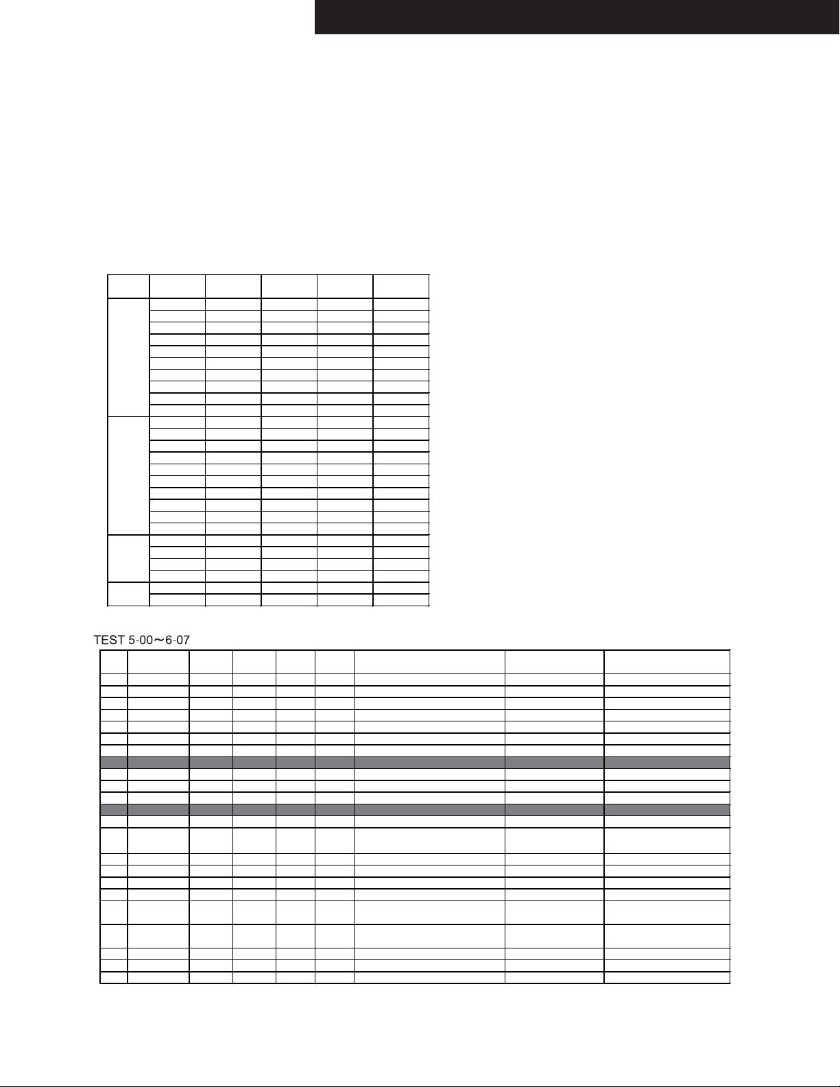
Video & HDMI Test mode
Input selector DIGITAL COMPO- Volume HDMI
5-00 BD/DVD HDMI IN1 51 IN1 DISC-D(BD) Tr.20or28
5-01 CBL/SAT HDMI IN2 5 1 IN2 DIS C-D(BD) Tr. 21
5-02 STB/DVR HDMI - 51 IN3 DISC-D(BD) Tr .21 or A(DVD)
5-03 GAME HDMI - 51 IN4 DISC-D(BD) Tr.21 o r A(DVD)
5-04 PC HDMI - 51 IN5 DISC- D(BD) Tr.2 1 or A(DVD)
5-05 IN6 HDMI - 51 IN6 DISC-D(BD) Tr.21 o r A( DVD)
5-06 IN7 HDMI - 51 IN7 DISC-D(BD) Tr.21 o r A( DVD)
IN8 HDMI - 51 IN8 DISC-D(BD) Tr.21 o r A( DVD)
5-07 AUX HDMI - 51 AUX Through(Main/Sub:Both), SPDIF DISC-D(BD) Tr.21 or A(DVD)
5-08 BD/DVD - IN1 MIN - 5-09 CBL/SAT - - MIN - -
BD/DVD - - MIN - CV > CV, COMPONENT
5-10 PC(RGB) - - MIN - RGB INPUT > HDMI OUT
5-11 PC/GAME HDMI - 51 IN5/IN4
6-00 BD/DVD HDMI IN1 60 IN3 DISC-C(SACD) TRACK12
6-01 BD/DVD COAX1* IN1 MIN - 6-02 CBL/SAT HDMI ARC IN2 40/60 - -
6-03 BD/DVD HDMI - 51 IN1 -
6-04 BD/DVD HDMI - 51 IN1 -
6-05 BD/DVD HDMI - 51 IN1 6-06 CBL/SAT HDMI - 51 IN2 6- 07 STB/DVR HDMI - 5 1 IN3 DISC-C(SACD) TRACK12
INPUT NENT
Through(Main/Sub:Both), I2S
Through(Main/Sub:Both), SPDIF
Through(Main/Sub:Both), SPDIF
Through(Main/Sub:Both), SPDIF
Through(Main/Sub:Both), SPDIF
Through(Main/Sub:Both), SPDIF
Through(Main/Sub:Both), SPDIF
Through(Main/Sub:Both), SPDIF
COMPONENT>HDMI(Main/Sub:Both)
CV (IN1)> HDMI(Main/Sub:Both)
Through(Main/Sub:Both)
Z2 HDMI TEST / HDMI Powered Z2
HDMI DSD SIGNAL
Audio TV OUT = ON, VOL=0
HDMI AUDIO RETURN CHANNEL
MHL Check(CABLE DET)
MHL Check(VBUS=OFF)
MHL Check(VBUS=ON)
CEC Z2relay Check
DSD(HDMI) DAC Direct check
MODE Refer ence TEST DISC*etc.
SP ALLch & SW-PO
SP ALLch & SW-PO
Audio out TV = ON
Audio out TV = ON
Audio out TV = ON
Audio out TV = ON
Audio out TV = ON
Audio out TV = ON
Audio out TV = ON
OUTPUT CH =
HDMI OUT is blue back
TX-NR1030/3030/ PR-SC5530/ DTR-60.6/70.6/ DHC-80.6
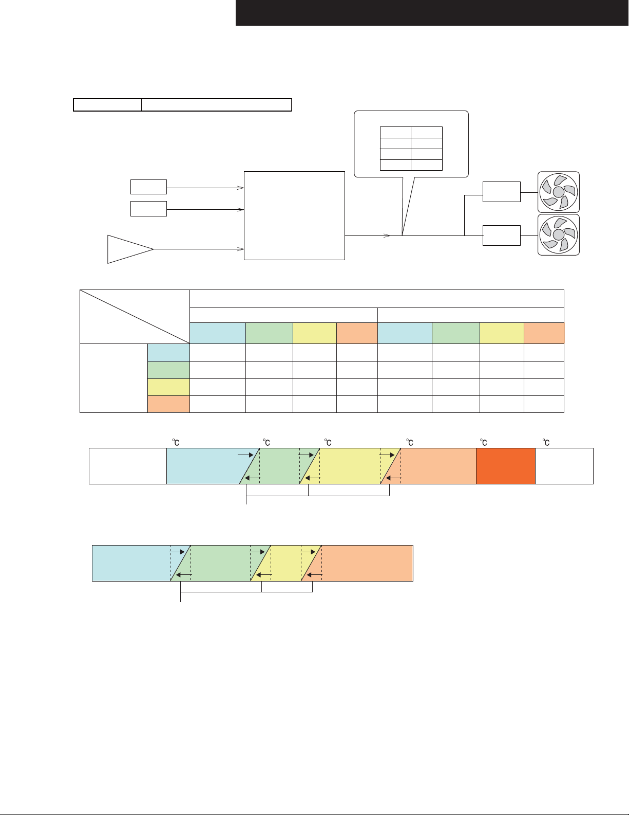
OPERATION CHECK-10
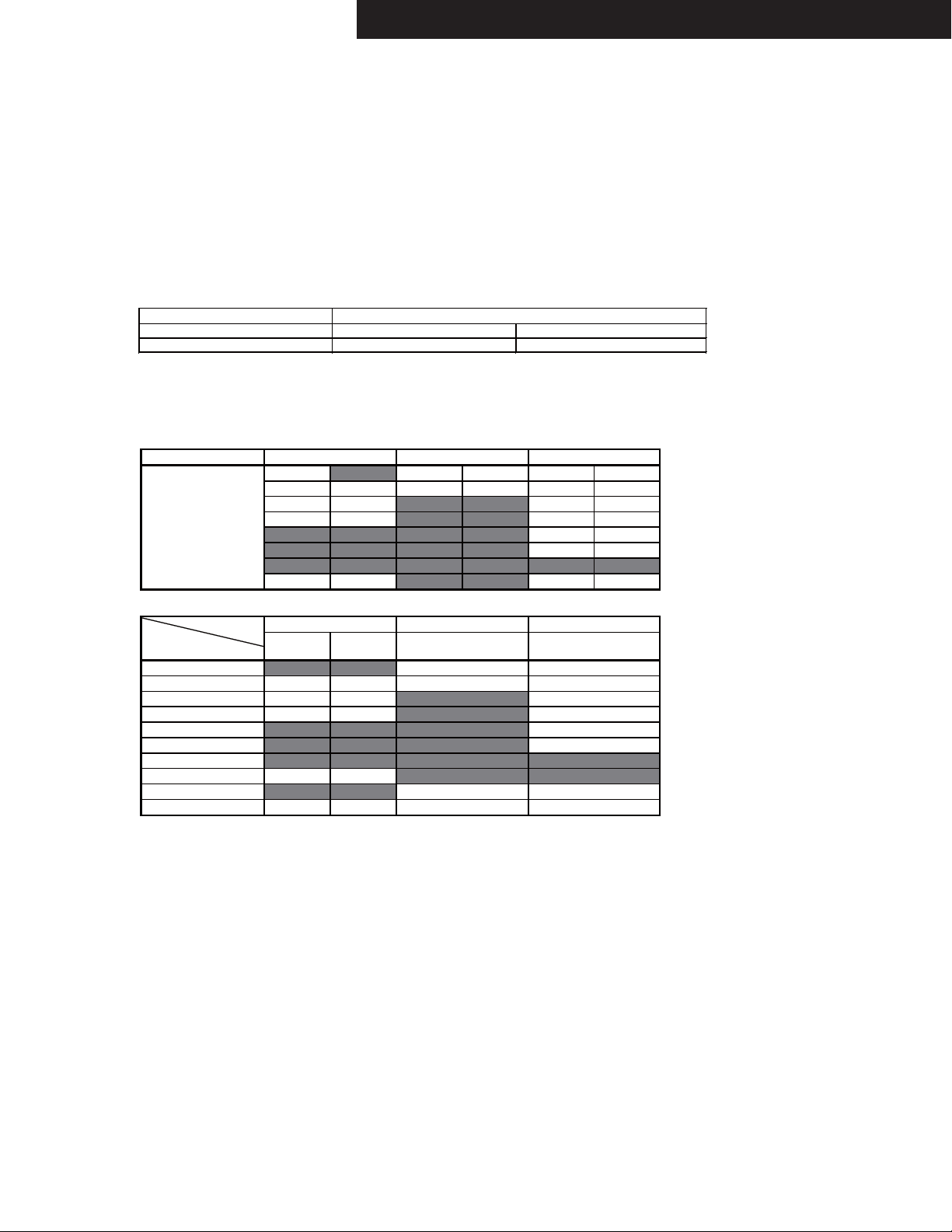
COOLING FAN(The following model only)
Applied model TX-NR1030/3030, DTR-60.6/70.6
Circuit
e.g.(TX-NR1030)
Thermal sensor
Q6980
Q6981
Power amp.
Condition to operate
OFF
THERMAL
(Temparature of
thermal sensor)
LOW
MID
THERMAL1
THERMAL2
VOLH
OFF or
Headphone
STOP
LOW
LOW
137
138
(Main Microprocessor)
139
Normal/ Bi-Amp Powerd Zone-2,3,4
LOW MID
STOP
Value D/A output of the MPU
OFF
LOW
MID
HIGH
0V
1.7V
2.2V
3.3V
Fan drive
Q6951
Q7011
MPU
FANCTRL
3
Q6592
VOLH(Voltage of VOLH port)
HIGH
STOP STOP STOPSTOP STOP STOP
LOWLOW
MID MID MIDMID MID MIDMID
LOW LOW LOW LOW LOW
OFF or
Headphone
LOW MID
COOLING FAN
HIGH
HIGH
MID
HIGH
HIGH HIGH HIGH HIGHHIGHHIGH
THERMAL
63
65 90 100
Shut down in
HIGH
10 minutes
continuously
Shut down
immediately
-30
45
OFF
Hysteresis control
50
LOW
52
55
MID
VOLH
0V
0.35V 0.4V 1.9V
OFF
Hysteresis control
LOW
2.2V 2.3V 3.3V
2.0V
MID
HIGH
How to check
1. How to check operation of Cooling Fan.
See “CONFIRMATION OF COOLING FAN OPERATION” in OPERATION CHECK-4.
2. How to check the value of THERMAL and VOLH.
See “CONFIRMATION OF OUTPUT VOLTAGE AND THERMAL SENSOR” in OPERATION CHECK-1.
Shut down
immediately
TX-NR1030/3030/ DTR-60.6/70.6
ADJUSTMENT PROCEDURE-1
ADJUSTMENT OF IDLING CURRENT
Applied to the following model.
(Model)
Procedure
a. Pre-adjustment
Set the following registers to minimum position before POWER ON.
Set the voltages at the following terminals to the following voltage by adjusting the following registers, under the condition of
no input and no load, immediately after POWER ON.
Channel L/C/R/ SL/SR/SBL/SBR/LH/RH/LW/RW
Check point(Terminals)
Adjustment point(Registers)
Voltage
b. Aging
Heat run during the following time.
Time
c. Final adjustment
Re-adjust by the following procedure after heat running for the above mentioned time.
L/C/R/SL/SR/SBL/SBR/LH/RH/LW/RW
Below
Between Do not adjust.
Over
TX-NR1030/3030, DTR-60.6/70.6
TX-NR1030, DTR-60.6TX-NR3030, DTR-70.6
L/C/R/ SL/SR/SBL/SBR/LH/RH
P6070㹼P6078
P6040㹼P6048
3.0mV
4mV 4mV
4䡚6mV
6mV 6mV
Connection
DC Volt meter
100ohms,
1/4W
AVR
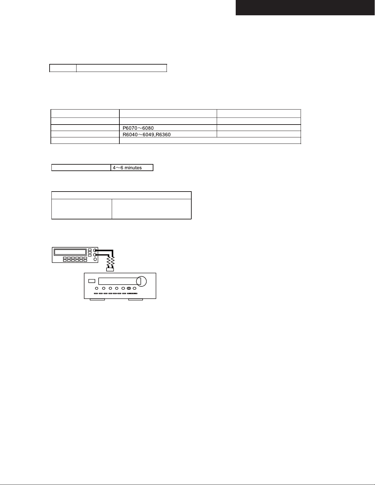
ADJUSTMENT PROCEDURE-2
ADJUSTMENT OF IDLING CURRENT
Check point and Adjustment point
Check point
Adjustment point
<Note>
TX-NR3030, DTR-70.6 only
TX-NR1030/3030/ DTR-60.6/70.6
RW
C
R6360 R6046R6048R6044 R6041R6042
RW
C
RSBRRHSR
P6071P6076P6078P6072P6080 P6074 P6070 P6079P6077P6075 P6073
R6040 R6045 R6047 R6043 R6049
RSBRRHSR
L
L
SBL
SBL
LH
LH
SL
SL
LW
LW
Power Amp. Block
To p

TX-NR1030 / 3030 / PR-SC5530 / DTR-60.6 / 70.6 / DHC-80.6
FIRMWARE UPDATE-1/2
USB Update (service mode)
CONFIDENTIALITY NOTICE:
The contents of the “Firmware Update” is “Confidential Information” as defined in the applicable “Service Center Agreement”.
It is for the exclusive use of Onkyo/Integra Authorized Independent Service Centers.
Dissemination or posting of this Firmware Update to any non-authorized individual or company is strictly prohibited.
Failure to keep this information confidential may result in the loss of service center authorization.
[Version Check]
Refer to “OPERATION CHECK-1” about the way of showing firmware version.
[Preparation]
1. Connect the USB storage device to your PC. If there is any data in the USB storage device, remove it.
2. Download the firmware file (package file) from the Onkyo FTP-server.
However European service partners should download the firmware file (package file) from the ExtraNet.
Onkyo FTP-server: ftp://manex.onkyo.co.jp/_servicefwa/TX-NR1030
ID and Password are those we informed when changed.
Filename is as follows: ONKAVR00xx_****************.zip
Unzip the downloaded file. A following file is created.
ONKAVR00xx_************.of1
ONKAVR00xx_************.of2
ONKAVR00xx_************.of3
ONKAVR00xx_************.of4
ONKAVR00xx_************.of5
3. Copy it to the USB storage device. Be careful not to copy the zip file.
4. Remove the USB storage device from your PC.

TX-NR1030 / 3030 / PR-SC5530 / DTR-60.6 / 70.6 / DHC-80.6
FIRMWARE UPDATE-2/2
USB Update (service mode)
[Procedure]
Overwriting is also possible.
1. Turn on the unit. It takes some time to start after you switch on the unit.
2. Select the USB input source.
3. Connect the USB storage device to USB port on the unit. Wait until Initializing of USB/NET finishes.
4. Hold down [DISPLAY] button and then press [ON/STANDBY] button twice.
Main version will be displayed, and HYBRID STANDBY indicator will start to flash.
5. Press [RETURN] button. “NET -> ALL_D” will be displayed.
6. Select “USB -> ALL_D” by [PRESET(left/right)] cursors and [TUNING(up/down)] cursors,
then press [ENTER] button, updating will begin.
7. Wait until update is completed. When the update ends, “Completed!” is displayed.
(If you leave it, it automatically turns standby mode. )
8. Press [ON/STANDBY] button, and the unit turns on.
9. Check the new FW version number.
<Note>
If the procedure might not be succesful, please select “USB -> ALL_M”.
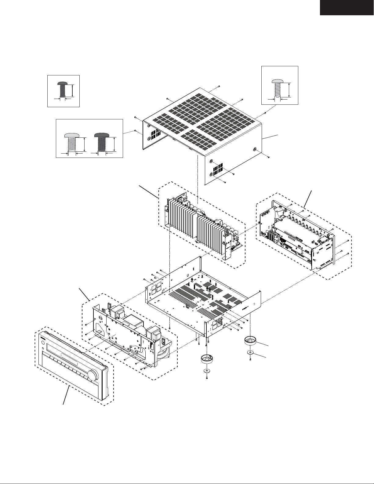
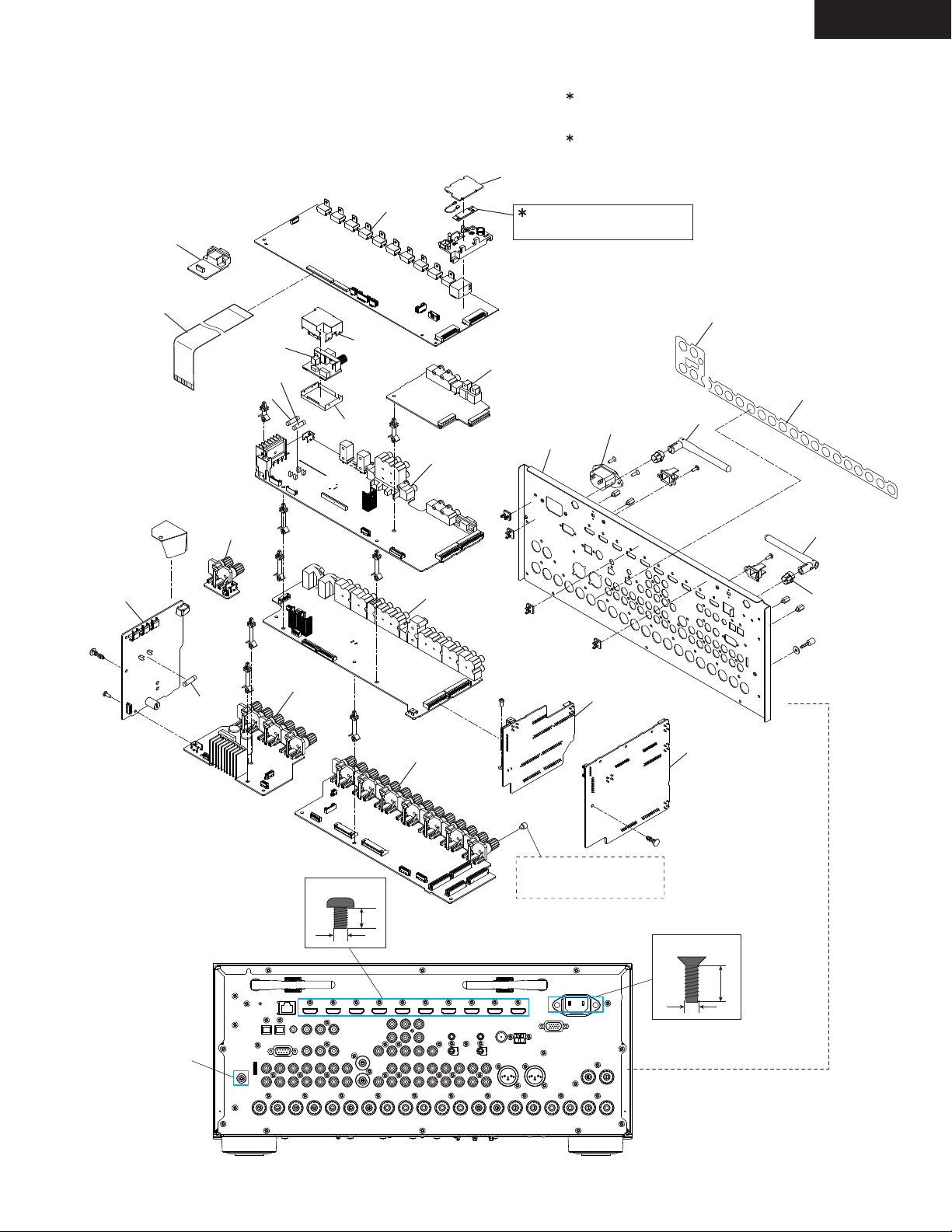
EXPLODED VIEWS-1
OVERALL
TX-NR3030
<NOTE>
No description screw is 3TTB+8B(3BC).
3TTB+8B(BC)
8
3
Unit : mm
Silver Model Black Model
4TTB+8C(NI)
4
4TTB+8C(3BC)
8
x 6 pcs.
8
4
Refer to
“EXPLODED VIEWS-4”
Silver Model
3TTB+8B(3CM)SR
8
3
A1601
Refer to
“EXPLODED VIEWS-5”
x 3 pcs.
Refer to
“EXPLODED VIEWS-3”
Refer to
“EXPLODED VIEWS-2”
A153 x 4pcs.
A155 x 4pcs.
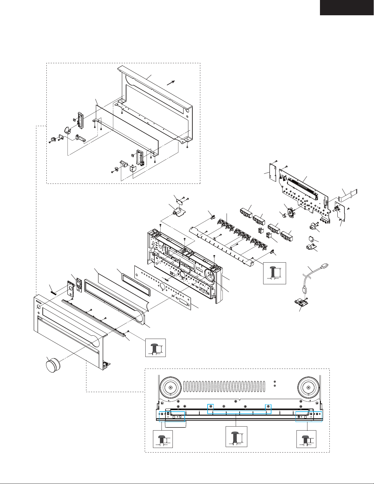
EXPLODED VIEWS-2
FRONT PANEL AS
TX-NR3030
DOOR SECTION
A427
A421
A591
A401
A423
A501
A539
U0047
FRONT
U0046
A523
A513
x 3 pcs.
A502
A583 (Plate)
U0041
A515
A517
2.6TTB+8B(3BC)
A509
A511
A517
A519
x 2 pcs.
A527
2.6
x 4 pcs.
U0040
P701
MIC
A515
U0044
U0045
OPT
U00491
U00490
P8691
8
HDMI
A521
A413
A409
3TTB+6B(BC)
3
x 4 pcs.
3P+6FN(3BC)
A433
U0100
6
BOTTOM VIEW
3TTB+10B(BC)
6
3
x 3 pcs.
3
x 2 pcs.
10
3P+6FN(3BC)
3
6
x 3 pcs.
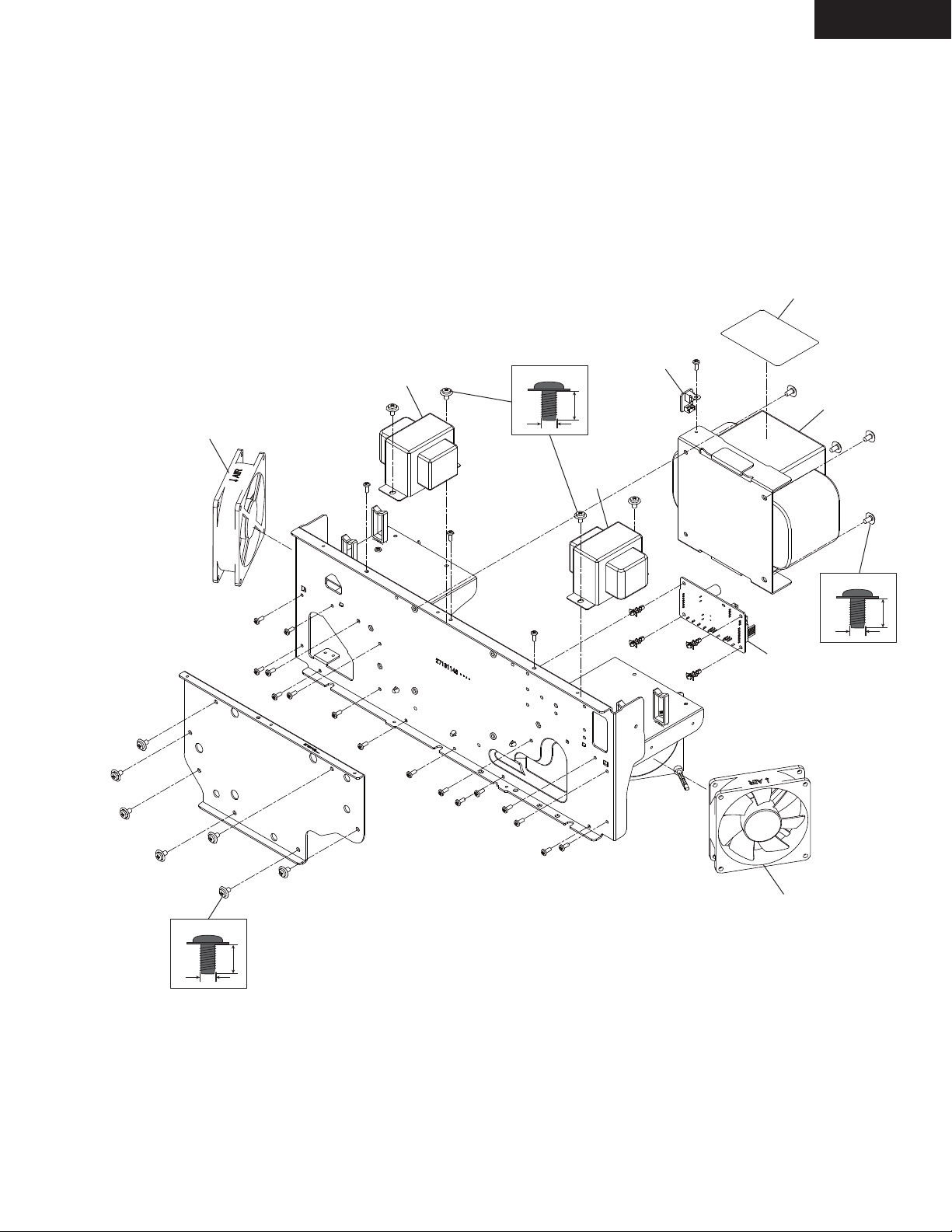
EXPLODED VIEWS-3
FRONT BRACKET AS(FAN, POWER TRANSFORMER)
TX-NR3030
A341
P061
or P062
T903
4TTC+8C(3BC)SR
4
8
x 4 pcs.
T902
U0014
T901
4TTC+8C(3BC)SR
8
4
x 4 pcs.
U0074
4TTC+8C(3BC)SR
4
x 7 pcs.
P061
or P062
8

TX-NR3030
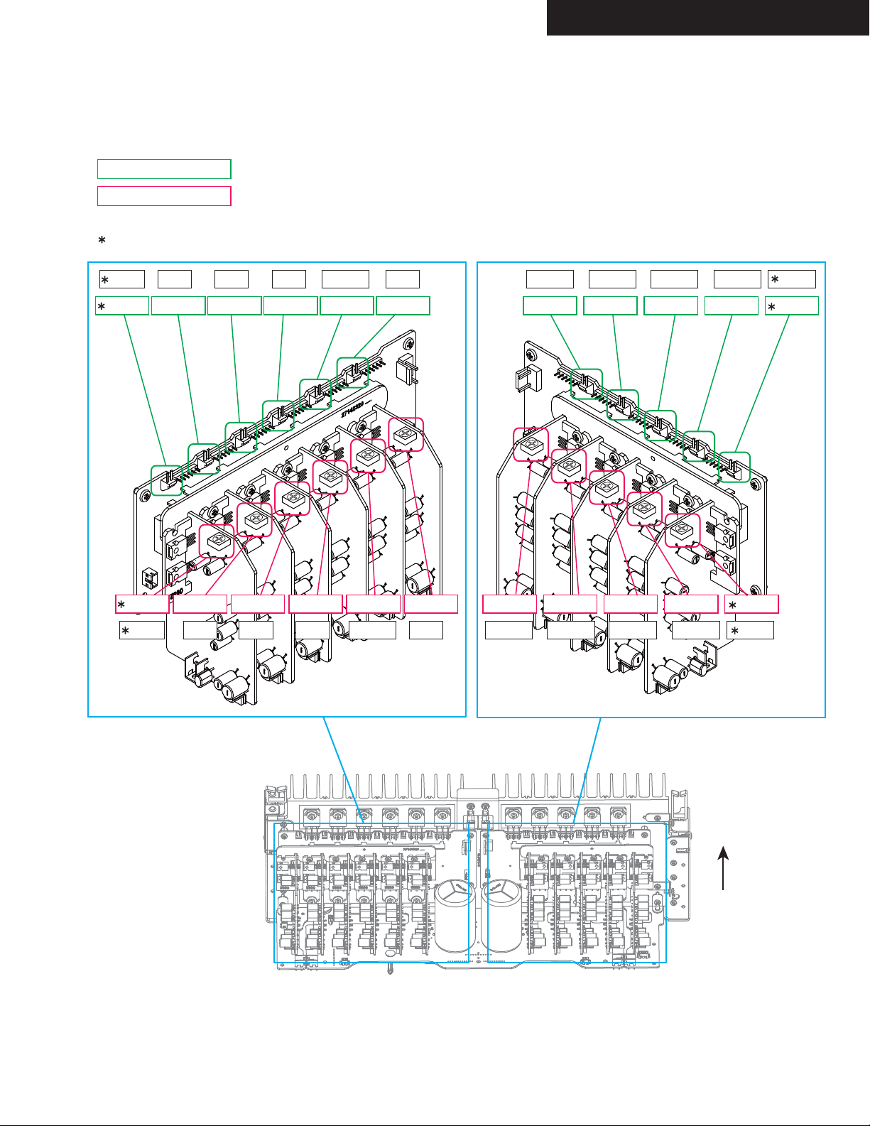
EXPLODED VIEWS-4
AMPLIFIER AS
U0026
U0025
3SMH10W.SW+15B(CU)
15
3
x 22 pcs.
3P+6FN(3BC)
3
x 8 pcs.
6
U0013
U0021
U0016
F6901
F6902
U0022
F6903
U0020
U0033
F6904
U0037
U0012
U0035
U0031
3TTW+8B(3BC)
8
3
x 4 pcs.
U0034
U0030
U0015
U0032
U0036
U0023
Q6090
Q6064
Q6062
Q6052
Q6054
Q6066Q6200
Q6068 Q6061
Q6058
Q6051
Q6056
Q6065
Q6060
Q6050
Q6055
U0024
Q6063
Q6067
Q6069
Q6057 Q6059
Q6053
U0010
U0011
3TTB+8B(3CM)SR
8
3
TX-NR3030
EXPLODED VIEWS-5
REAR AS
U0072
P2101
U0120
F2000
F2002
U0051
U0120A
U0120B
U0080
U0060
WiFi & Bluetooth Module has already been certificated
by FCC and IC.
“Refer to EXPLODED VIEWS-6”
This module transmitter does not have RF shielding,
therefore it will be equipped only the tested Audio system
mentioning this document.
U0090
Additional test will be required if it will be equipped to the
other devices
WiFi & Bluetooth Module
U020A
<NOTE>
U020 = U020A + U020B + U020C + U020D
A393
U0073
P9000
U020B
A355
A391
U020C
U0053
Terminal
(SN:25060151)
F9002
U0052
3P+6FN(3BC)
3
6
U0061
U0050
x 10 pcs.
U0071
Except MDC,MJJ
P6800 x 22 pcs.
U0070
3TTF+10B(3BC)
10
3
U020D
x 2 pcs.
x 2 pcs.

EXPLODED VIEWS-6
WiFi & Bluetooth Module has already been certificated by FCC and IC.
Information to the user.
Indicate "Contains FCC ID: TX2-RTL8723AS", "Contains IC: 6317A- RTL8723AS" and following information to the host
device installed.
This device complies with part 15 of the FCC Rules. Operation is subject to the following two conditions: (1) This
device may not cause harmful interference, and (2) this device must accept any interference received, including
interference that may cause undesired operation.
Describe the following sentence to a user's manual of the host device.
[For FCC]
FCC CAUTION
Changes or modifications not expressly approved by the party responsible for compliance could void the user’s
authority to operate the equipment.
Note: This equipment has been tested and found to comply with the limits for a Class B digital device, pursuant
to part 15 of the FCC Rules. These limits are designed to provide reasonable protection against harmful interference
in a residential installation. This equipment generates, uses and can radiate radio frequency energy and, if
not installed and used in accordance with the instructions, may cause harmful interference to radio communications.
However, there is no guarantee that interference will not occur in a particular installation. If this equipment
does cause harmful interference to radio or television reception, which can be determined by turning the
equipment off and on, the user is encouraged to try to correct the interference by one or more of the following
measures:
—Reorient or relocate the receiving antenna.
—Increase the separation between the equipment and receiver.
—Connect the equipment into an outlet on a circuit different from that to which the receiver is connected.
—Consult the dealer or an experienced radio/TV technician for help.
TX-NR3030
This transmitter must not be co-located or operated in conjunction with any other antenna or transmitter.
This equipment complies with FCC radiation exposure limits set forth for an uncontrolled environment and meets
the FCC radio frequency (RF) Exposure Guidelines in Supplement C to OET65. This equipment has very low
levels of RF energy that it deemed to comply without maximum permissive exposure evaluation (MPE). But it is
desirable that it should be installed and operated keeping the radiator at least 20cm or more away from person’s
body (excluding extremities: hands, wrists, feet and ankles).
[For IC]
CAN ICES-3 B/NMB-3 B
This device complies with Industry Canada licence-exempt RSS standard(s). Operation is subject to the following
two conditions: (1) this device may not cause interference, and (2) this device must accept any interference,
including interference that may cause undesired operation of the device.
Le présent appareil est conforme aux CNR d'Industrie Canada applicables aux appareils radio exempts de
licence. L'exploitation est autorisée aux deux conditions suivantes : (1) l'appareil ne doit pas produire de
brouillage, et (2) l'utilisateur de l'appareil doit accepter tout brouillage radioélectrique subi, même si le brouillage
est susceptible d'en compromettre le fonctionnement.
This equipment complies with IC radiation exposure limits set forth for an uncontrolled environment and meets
RSS-102 of the IC radio frequency (RF) Exposure rules. This equipment has very low levels of RF energy that it
deemed to comply without maximum permissive exposure evaluation (MPE). But it is desirable that it should be
installed and operated keeping the radiator at least 20cm or more away from person’s body (excluding extremities:
hands, wrists, feet and ankles).
Cet équipement est conforme aux limites d’exposition aux rayonnements énoncées pour un environnement non
contrôlé et respecte les règles d’exposition aux fréquences radioélectriques (RF) CNR-102 de l’IC. Cet équipement
émet une énergie RF très faible qui est considérée conforme sans évaluation de l’exposition maximale
autorisée. Cependant, cet équipement doit être installé et utilisé en gardant une distance de 20 cm ou plus entre
le dispositif rayonnant et le corps (à l’exception des extrémités : mains, poignets, pieds et chevilles).
 Loading...