


 Loading...
AV RECEIVER
TX-NR626
Instruction Manual
Contents |
|
Safety Information and Introduction |
............2 |
Table of Contents........................................... |
6 |
Connections ................................................. |
12 |
Turning On & Basic Operations.................. |
21 |
Playback........................................................ |
29 |
Advanced Operations .................................. |
48 |
Controlling Other Components................... |
71 |
Appendix....................................................... |
77 |
Internet Radio Guide |
|
Remote Control Codes |
|
En
WARNING:
TO REDUCE THE RISK OF FIRE OR ELECTRIC SHOCK, DO NOT EXPOSE THIS APPARATUS TO RAIN OR MOISTURE.
CAUTION:
TO REDUCE THE RISK OF ELECTRIC SHOCK, DO NOT REMOVE COVER (OR BACK). NO USER-SERVICEABLE PARTS INSIDE. REFER SERVICING TO QUALIFIED SERVICE PERSONNEL.
WARNING |
|
AVIS |
RISK OF ELECTRIC SHOCK |
|
RISQUE DE CHOC ELECTRIQUE |
DO NOT OPEN |
|
NE PAS OUVRIR |
|
|
|
The lightning flash with arrowhead symbol, within an equilateral triangle, is intended to alert the user to the presence of uninsulated “dangerous voltage” within the product’s enclosure that may be of sufficient magnitude to constitute a risk of electric shock to persons.
The exclamation point within an equilateral triangle is intended to alert the user to the presence of important operating and maintenance (servicing) instructions in the literature accompanying the appliance.
Important Safety Instructions
1.Read these instructions.
2.Keep these instructions.
3.Heed all warnings.
4.Follow all instructions.
5.Do not use this apparatus near water.
6.Clean only with dry cloth.
7.Do not block any ventilation openings. Install in accordance with the manufacturer’s instructions.
8.Do not install near any heat sources such as radiators, heat registers, stoves, or other apparatus (including amplifiers) that produce heat.
9.Do not defeat the safety purpose of the polarized or grounding-type plug. A polarized plug has two blades with one wider than the other. A grounding type plug has two blades and a third grounding prong. The wide blade or the third prong are provided for your safety. If the provided plug does not fit into your outlet, consult an electrician for replacement of the obsolete outlet.
10.Protect the power cord from being walked on or pinched particularly at plugs, convenience receptacles, and the point where they exit from the apparatus.
11.Only use attachments/accessories specified by
the manufacturer.
12. Use only with the cart, stand, tripod, bracket, or table specified by the manufacturer, or sold with the apparatus. When a cart is used, use caution when
moving the cart/apparatus
S3125A
combination to avoid injury from tip-over.
13.Unplug this apparatus during lightning storms or when unused for long periods of time.
14.Refer all servicing to qualified service personnel. Servicing is required when the apparatus has been damaged in any way, such as power-supply cord or plug is damaged, liquid has been spilled or objects have fallen into the apparatus, the apparatus has been exposed to rain or moisture, does not operate normally, or has been dropped.
15.Damage Requiring Service
Unplug the apparatus from the wall outlet and refer servicing to qualified service personnel under the following conditions:
A.When the power-supply cord or plug is damaged,
Safety Information and Introduction
B.If liquid has been spilled, or objects have fallen into the apparatus,
C.If the apparatus has been exposed to rain or water,
D.If the apparatus does not operate normally by following the operating instructions. Adjust only those controls that are covered by the operating instructions as an improper adjustment of other controls may result in damage and will often require extensive work by a qualified technician to restore the apparatus to its normal operation,
E.If the apparatus has been dropped or damaged in any way, and
F.When the apparatus exhibits a distinct change in performance this indicates a need for service.
16.Object and Liquid Entry
Never push objects of any kind into the apparatus through openings as they may touch dangerous voltage points or short-out parts that could result in a fire or electric shock.
The apparatus shall not be exposed to dripping or splashing and no objects filled with liquids, such as vases shall be placed on the apparatus.
Don’t put candles or other burning objects on top of this unit.
17.Batteries
Always consider the environmental issues and follow local regulations when disposing of batteries.
18.If you install the apparatus in a built-in installation, such as a bookcase or rack, ensure that there is adequate ventilation.
Leave 20 cm (8") of free space at the top and sides and 10 cm (4") at the rear. The rear edge of the shelf or board above the apparatus shall be set 10 cm (4") away from the rear panel or wall, creating a flue-like gap for warm air to escape.
En-2

Precautions
1.Recording Copyright—Unless it’s for personal use only, recording copyrighted material is illegal without the permission of the copyright holder.
2.AC Fuse—The AC fuse inside the unit is not userserviceable. If you cannot turn on the unit, contact your Onkyo dealer.
3.Care—Occasionally you should dust the unit all over with a soft cloth. For stubborn stains, use a soft cloth dampened with a weak solution of mild detergent and water. Dry the unit immediately afterwards with a clean cloth. Don’t use abrasive cloths, thinners, alcohol, or other chemical solvents, because they may damage the finish or remove the panel lettering.
4.Power WARNING
BEFORE PLUGGING IN THE UNIT FOR THE FIRST TIME, READ THE FOLLOWING SECTION CAREFULLY.
AC outlet voltages vary from country to country. Make sure that the voltage in your area meets the voltage requirements printed on the unit’s rear panel (e.g., AC 230 V, 50 Hz or AC 120 V, 60 Hz).
The power cord plug is used to disconnect this unit from the AC power source. Make sure that the plug is readily operable (easily accessible) at all times.
For models with [POWER] button, or with both [POWER] and [ON/STANDBY] buttons: Pressing the [POWER] button to select OFF mode does not fully disconnect from the mains. If you do not intend to use the unit for an extended
period, remove the power cord from the AC outlet.
For models with [ON/STANDBY] button only: Pressing the [ON/STANDBY] button to select Standby mode does not fully disconnect from the mains. If you do not intend to use the unit for an
extended period, remove the power cord from the AC outlet.
5.Preventing Hearing Loss Caution
Excessive sound pressure from earphones and headphones can cause hearing loss.
6.Batteries and Heat Exposure Warning
Batteries (battery pack or batteries installed) shall not be exposed to excessive heat as sunshine, fire or the like.
7.Never Touch this Unit with Wet Hands—Never handle this unit or its power cord while your hands are wet or damp. If water or any other liquid gets inside this unit, have it checked by your Onkyo dealer.
8.Handling Notes
•If you need to transport this unit, use the original packaging to pack it how it was when you originally bought it.
•Do not leave rubber or plastic items on this unit for a long time, because they may leave marks on the case.
•This unit’s top and rear panels may get warm after prolonged use. This is normal.
•If you do not use this unit for a long time, it may not work properly the next time you turn it on, so be sure to use it occasionally.
For U.S. and Canadian models
FCC CAUTION
Changes or modifications not expressly approved by the party responsible for compliance could void the user’s authority to operate the equipment.
Note:
This equipment has been tested and found to comply with the limits for a Class B digital device, pursuant to part 15 of the FCC Rules. These limits are designed to provide reasonable protection against harmful
En-3
Safety Information and Introduction
interference in a residential installation. This equipment generates, uses and can radiate radio frequency energy and, if not installed and used in accordance with the instructions, may cause harmful interference to radio communications. However, there is no guarantee that interference will not occur in a particular installation. If this equipment does cause harmful interference to radio or television reception, which can be determined by turning the equipment off and on, the user is encouraged to try to correct the interference by one or more of the following measures:
–Reorient or relocate the receiving antenna. –Increase the separation between the equipment
and receiver.
–Connect the equipment into an outlet on a circuit different from that to which the receiver is connected.
–Consult the dealer or an experienced radio/TV technician for help.
This device complies with Industry Canada licenceexempt RSS standard(s). Operation is subject to the following two conditions: (1) this device may not cause interference, and (2) this device must accept any interference, including interference that may cause undesired operation of the device.
Le présent appareil est conforme aux CNR d’Industrie Canada applicables aux appareils radio exempts de licence. L’exploitation est autorisée aux deux conditions suivantes : (1) l’appareil ne doit pas produire de brouillage, et (2) l’utilisateur de l’appareil doit accepter tout brouillage radioélectrique subi, même si le brouillage est susceptible d’en compromettre le fonctionnement.
This transmitter must not be co-located or operated in conjunction with any other antenna or transmitter.

RF Exposure Compliance
This equipment complies with FCC/IC radiation exposure limits set forth for an uncontrolled environment and meets the FCC radio frequency (RF) Exposure Guidelines in Supplement C to OET65 and RSS-102 of the IC radio frequency (RF) Exposure rules. This equipment has very low levels of RF energy that it deemed to comply without maximum permissive exposure evaluation (MPE). But it is desirable that it should be installed and operated keeping the radiator at least 20 cm or more away from person’s body (excluding extremities: hands, wrists, feet and ankles).
Cet équipement est conforme aux limites d’exposition aux rayonnements énoncées pour un environnement non contrôlé et respecte les régles les radioélectriques (RF) de la FCC lignes directrices d’exposition dans le Supplément C à OET65 et d’exposition aux fréquences radioélectriques (RF) CNR-102 de l’IC. Cet équipement émet une énergie RF trés faible qui est considérée conforme sans évaluation de l’exposition maximale autorisée. Cependant, cet équipement doit être installé et utilisé en gardant une distance de 20 cm ou plus entre le dispositif rayonnant et le corps (à l’exception des extrémités : mains, poignets, pieds et chevilles).
For Canadian Models
NOTE: THIS CLASS B DIGITAL APPARATUS COMPLIES WITH CANADIAN ICES-003.
For models having a power cord with a polarized plug:
CAUTION: TO PREVENT ELECTRIC SHOCK, MATCH WIDE BLADE OF PLUG TO WIDE SLOT, FULLY INSERT.
Modèle pour les Canadien
REMARQUE: CET APPAREIL NUMÉRIQUE DE LA CLASSE B EST CONFORME À LA NORME NMB-003 DU CANADA.
Sur les modèles dont la fiche est polarisée: ATTENTION: POUR ÉVITER LES CHOCS ÉLECTRIQUES, INTRODUIRE LA LAME LA PLUS LARGE DE LA FICHE DANS LA BORNE CORRESPONDANTE DE LA PRISE ET POUSSER JUSQU’AU FOND.
For British models
Replacement and mounting of an AC plug on the power supply cord of this unit should be performed only by qualified service personnel.
IMPORTANT
The wires in the mains lead are coloured in accordance with the following code:
Blue: Neutral Brown: Live
As the colours of the wires in the mains lead of this apparatus may not correspond with the coloured markings identifying the terminals in your plug, proceed as follows:
The wire which is coloured blue must be connected to the terminal which is marked with the letter N or coloured black.
The wire which is coloured brown must be connected to the terminal which is marked with the letter L or coloured red.
En-4
Safety Information and Introduction
IMPORTANT
The plug is fitted with an appropriate fuse. If the fuse needs to be replaced, the replacement fuse must approved by ASTA or BSI to BS1362 and have the same ampere rating as that indicated on the plug. Check for the ASTA mark or the BSI mark on the body of the fuse.
If the power cord’s plug is not suitable for your socket outlets, cut it off and fit a suitable plug. Fit a suitable fuse in the plug.
For European Models
Declaration of Conformity
We declare, under our sole responsibility, that this product complies with the standards:
–Safety
–Limits and methods of
measurement of radio disturbance characteristics –Limits for harmonic current emissions
–Limitation of voltage changes, voltage fluctuations and flicker
–RoHS Directive, 2011/65/EU
–Hereby, Onkyo Corporation, declares that this TX-NR626 is in compliance with the essential requirements and other relevant provisions of Directive 1999/5/EC.
–Снастоящето, Onkyo Corporation, декларира, че TX-NR626 е в съответствие със съществените изисквания и другитеприложими разпоредби на Директива 1999/5/EC.
–Onkyo Corporation tímto prohlašuje, že TX-NR626 splňuje základní požadavky a všechna příslušná ustanoveni Směrnice 1999/5/ES.
–Undertegnede Onkyo Corporation erklærer herved, at følgende udstyr TX-NR626 overholder de væsentlige krav og øvrige relevante krav i direktiv 1999/5/EF.
–Hiermit erklärt Onkyo Corporation, dass sich das Gerät TX-NR626 in Übereinstimmung mit den grundlegenden Anforderungen und den übrigen einschlägigen Bestimmungen der Richtlinie 1999/5/EG befindet.
–Käesolevaga kinnitab Onkyo Corporation seadme TX-NR626 vastavust direktiivi 1999/5/EÜ põhinõuetele ja nimetatud direktiivist tulenevatele teistele asjakohastele sätetele.
–ΜΕ ΤΗΝ ΠΑΡΟΥΣΑ Ο ΚΑΤΑΣΚΕΥΑΣΤΗΣ Onkyo Corporation ∆ΗΛΩΝΕΙ ΟΤΙ TX-NR626
ΣΥΜΜΟΡΦΩΝΕΤΑΙ ΠΡΟΣ ΤΙΣ ΟΥΣΙΩ∆ΕΙΣ ΑΠΑΙΤΗΣΕΙΣ ΚΑΙ ΤΙΣ ΛΟΙΠΕΣ ΣΧΕΤΙΚΕΣ ∆ΙΑΤΑΞΕΙΣ ΤΗΣ Ο∆ΗΓΙΑΣ 1999/5/ΕΚ
–Por la presente, Onkyo Corporation, declara que este TX-NR626 cumple con los requisitos esenciales y otras exigencias relevantes de la Directiva 1999/5/EC.
–Par la présente, Onkyo Corporation déclare que l’appareil TX-NR626 est conforme aux exigences essentielles et aux autres dispositions pertinentes de la directive 1999/5/CE.
–Con la presente Onkyo Corporation dichiara che questo TX-NR626 è conforme ai requisiti essenziali ed alle altre disposizioni pertinenti stabilite dalla direttiva 1999/5/CE.
–Ar šo Onkyo Corporation deklarē, ka TX-NR626 atbilst Direktīvas 1999/5/EK būtiskajām prasībām un citiem ar to saistītajiem noteikumiem.
–Šiuo Onkyo Corporation deklaruoja, kad šis TX-NR626 atitinka esminius reikalavimus ir kitas 1999/5/EB Direktyvos nuostatas.
–A Onkyo Corporation ezzennel kijelenti, hogy a TX-NR626 típusú beren-dezés teljesíti az alapvető követelményeket és más 1999/5/EK irányelvben meghatározott vonatkozó rendelkezéseket.
–Hierbij verklaart Onkyo Corporation dat het toestel l TX-NR626 in overeenstemming is met de
essentiële eisen en de andere relevante bepalingen van richtlijn 1999/5/EG.
–Niniejszym Onkyo Corporation deklaruje że TX-NR626 jest zgodny z zasadniczymi wymaganiami i innymi właściwymi postanowieniami Dyrektywy 1999/5/EC.
–Eu, Onkyo Corporation, declaro que o TX-NR626 cumpre os requisitos essenciais e outras provisões relevantes da Directiva 1999/5/EC.
–Prin prezenta, Onkyo Corporation, declară că aparatul TX-NR626 este în conformitate cu cerinţele esenţiale şi cu alte prevederi pertinente ale Directivei 1999/5/CE.
–Onkyo Corporation týmto vyhlasuje, že TX-NR626 a spĺňa základné požiadavky a všetky príslušné ustanovenia Smernice 1999/5/ES.
–Onkyo Corporation izjavlja, da je ta TX-NR626 v skladu z bistvenimi zahtevami in drugimi relevantnimi določili direktive 1999/5/ES.
–Onkyo Corporation vakuuttaa täten että TX-NR626 tyyppinen laite on direktiivin 1999/5/EY oleellisten vaatimusten ja sitä koskevien direktiivin muiden ehtojen mukainen.
–Härmed förklarar Onkyo Corporation att denna TX-NR626 följer de väsentliga kraven och andra relevanta stadgar i Direktiv 1999/5/EC.
–Hér með lýsir Onkyo Corporation því yfir að varan TX-NR626 er í samræmi við grunnkröfur og aðrar kröfur sem gerðar eru í tilskipun 1999/5/EC.
–Onkyo Corporation erklærer herved at denne TX-NR626 er i overensstemmelse med vesentlige krav og andre relevante bestemmelser i direktiv 1999/5/EC.
|
|
Safety Information and Introduction |
|
|
|
|
|
Complies with |
|
23764/SDPPI/2012 |
|
IDA Standards |
|
2371 |
|
DA106032 |
|
|
|
|
|
|
|
TA-20120424004
TRA
REGISTERED No
ER0086260/12
DEALER No
527090
Thank you for purchasing an Onkyo AV Receiver. Please read this manual thoroughly before making connections and plugging in the unit.
Following the instructions in this manual will enable you to obtain optimum performance and listening enjoyment from your new AV Receiver. Please retain this manual for future reference.
Supplied Accessories
Make sure you have the following accessories:
Indoor FM antenna ( page 19)
AM loop antenna ( page 19)
Power cord (Taiwanese models) ( page 21)
Speaker cable labels ( page 12)
Speaker setup microphone ( page 25)
Remote controller (RC-866M) and two batteries (AA/R6)
Quick Start Guide
*In catalogs and on packaging, the letter at the end of the product name indicates the color. Specifications and operations are the same regardless of color.
En-5

Table of Contents |
|
Safety Information and Introduction |
|
Important Safety Instructions ...................................... |
2 |
Precautions ................................................................... |
3 |
Supplied Accessories................................................... |
5 |
Table of Contents.......................................................... |
6 |
Features ......................................................................... |
7 |
Front & Rear Panels...................................................... |
8 |
Front Panel.................................................................. |
8 |
Display ........................................................................ |
9 |
Rear Panel ................................................................ |
10 |
Remote Controller....................................................... |
11 |
Controlling the AV Receiver ...................................... |
11 |
Connections |
|
Connecting the AV Receiver...................................... |
12 |
Connecting Your Speakers ....................................... |
12 |
Connecting the TV/AV components.......................... |
15 |
About RIHD-compatible components........................ |
16 |
Operations that can be performed |
|
with RIHD connection ............................................. |
17 |
Confirm the settings .................................................. |
17 |
Connection Tips ........................................................ |
17 |
Connecting the Antennas.......................................... |
19 |
Connecting Onkyo RI Components........................... |
20 |
Using Headphones.................................................... |
20 |
Turning On & Basic Operations |
|
Turning On/Off the AV Receiver ................................ |
21 |
Connecting the Power Cord ...................................... |
21 |
Turning On ................................................................ |
21 |
Turning Off ................................................................ |
21 |
Firmware Update Notification.................................... |
22 |
About the HYBRID STANDBY indicator.................... |
22 |
Initial Setup ................................................................. |
22 |
Selecting the Language |
|
for the On-screen Setup Menus ............................. |
22 |
Audyssey MultEQ: Auto Setup ................................. |
22 |
Source Connection ................................................... |
23 |
Remote Mode Setup................................................. |
23 |
Network Connection ................................................. |
23 |
Terminating the Initial Setup ..................................... |
23 |
Using the Automatic Speaker Setup......................... |
24 |
Performing Wireless LAN Setup ............................... |
27 |
Playback |
|
Playback ...................................................................... |
29 |
Controlling Contents of USB or Network Devices..... |
30 |
Understanding Icons on the Display ......................... |
31 |
Playing an Audio from Bluetooth-enabled Device .... |
31 |
Playing a USB Device............................................... |
32 |
Listening to TuneIn ................................................... |
32 |
Registering Other Internet Radio .............................. |
34 |
Changing the Icon Layout |
|
on the Network Service Screen.............................. |
34 |
Playing Music Files on a Server (DLNA) .................. |
34 |
Playing Music Files on a Shared Folder ................... |
36 |
Remote Playback...................................................... |
37 |
Listening to AM/FM Radio ........................................ |
38 |
Playing Audio and Video from Separate Sources..... |
40 |
Using the Listening Modes ....................................... |
41 |
Displaying Source Information.................................. |
45 |
Using the Sleep Timer .............................................. |
45 |
Setting the Display Brightness.................................. |
46 |
Changing the Input Display....................................... |
46 |
Muting the AV Receiver ............................................ |
46 |
Using the Home Menu .............................................. |
47 |
|
Safety Information and Introduction |
|
Advanced Operations |
|
|
On-screen Setup......................................................... |
48 |
|
Using the Quick Setup.............................................. |
48 |
|
Using the Audio Settings of Quick Setup.................. |
49 |
|
Using the Setup Menu (HOME)................................ |
52 |
|
Setup Menu Items .................................................... |
52 |
|
1. |
Input/Output Assign.............................................. |
53 |
2. |
Speaker Setup...................................................... |
55 |
3. |
Audio Adjust ......................................................... |
57 |
4. |
Source Setup........................................................ |
58 |
5. |
Listening Mode Preset.......................................... |
63 |
6. |
Miscellaneous....................................................... |
63 |
7. |
Hardware Setup.................................................... |
64 |
8. |
Remote Controller Setup ...................................... |
68 |
9. |
Lock Setup............................................................ |
68 |
Zone 2.......................................................................... |
69 |
|
Making Zone 2 Connections..................................... |
69 |
|
Controlling Zone 2 Components............................... |
70 |
|
Controlling Other Components |
|
|
Controlling Other Components................................. |
71 |
|
Preprogrammed Remote Control Codes .................. |
71 |
|
Looking up for Remote Control Codes ..................... |
71 |
|
Entering Remote Control Codes............................... |
71 |
|
Remapping Colored Buttons .................................... |
72 |
|
Remote Control Codes for Onkyo Components |
|
|
Connected via RI ................................................... |
72 |
|
Resetting the REMOTE MODE Buttons ................... |
72 |
|
Resetting the Remote Controller .............................. |
72 |
|
Controlling Other Components ................................. |
73 |
|
Using the Onkyo Dock.............................................. |
75 |
|
Controlling Your iPod/iPhone ................................... |
76 |
|
Appendix |
|
Troubleshooting ......................................................... |
77 |
Firmware Update ........................................................ |
85 |
About HDMI................................................................. |
88 |
Network/USB Features............................................... |
89 |
License and Trademark Information ........................ |
91 |
Specifications ............................................................. |
92 |
To reset the AV receiver, see page 77.
En-6

Features
Amplifier
•95 Watts/Channel @ 8 ohms (FTC)
•160 Watts/Channel @ 6 ohms (IEC)
•175 Watts/Channel @ 6 ohms (JEITA)
•WRAT–Wide Range Amplifier Technology (5 Hz to 100 kHz bandwidth)
•Optimum Gain Volume Circuitry
•H.C.P.S. (High Current Power Supply) Massive High Power Transformer
Processing
•Incorporates Qdeo™ technology for HDMI Video Upscaling (to 4K Compatible)
•HDMI (Audio Return Channel, 3D, DeepColor, x.v.Color, Lip Sync, 4K (up-scaling and Passthrough), DTS-HD Master Audio, DTS-HD High Resolution Audio, Dolby TrueHD, Dolby Digital Plus, DSD and Multi-CH PCM)
•Dolby TrueHD and DTS-HD Master Audio
•Dolby Pro Logic IIz
•Non-Scaling Configuration
•A-Form Listening Mode Memory
•Direct Mode
•Pure Audio Mode (European, Australian and Asian models)
•Music Optimizer for Compressed Digital Music files
•Phase Matching Bass System
•192 kHz/24-bit D/A Converters
•Powerful and Highly Accurate 32-bit Processing DSP
•Jitter Cleaning Circuit Technology
Safety Information and Introduction
Connections
•6 HDMI Inputs and 2 Outputs
•4K (up-scaling and Passthrough*)-compatible HDMI Inputs
*Compatible with HDMI IN 1 to HDMI IN 4 only
•Onkyo pfor System Control
•3 Digital Inputs (1 Optical/2 Coaxial)
•Component Video Switching (1 Input/1 Output)
•Banana Plug-Compatible Speaker Posts
*In Europe, using banana plugs to connect speakers to an audio amplifier is prohibited.
•Powered Zone 2
•Bi-Amping Capability for FL/FR with SBL/SBR
•Internet Radio Connectivity
•Network Capability for Streaming Audio Files
•Wi-Fi (Wireless LAN) Connectivity
•Wireless Music Playback via Bluetooth
•Front-Panel USB Input for Memory Devices
•MHL-Enabled HDMI IN 1
Miscellaneous
•40 FM/AM Presets
•Audyssey MultEQ® to correct room acoustic problems
•Audyssey Dynamic EQ® for loudness correction
•Audyssey Dynamic Volume® to maintain optimal listening level and dynamic range
•Crossover Adjustment (40/50/60/70/80/90/100/120/150/200 Hz)
•A/V Sync Control Function (up to 800 ms)
•Auto Standby Function
•On-Screen Display via HDMI
•Preprogrammed u-Compatible Remote
En-7
Safety Information and Introduction
Front & Rear Panels
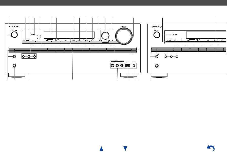
Front Panel
(North American and Taiwanese models) |
(European, Australian and Asian models) |
a |
bcde |
f g |
h i j k l m n |
o |
p q r |
s |
t u v w |
p |
x |
y |
For detailed information, see the pages in parentheses.
a 8ON/STANDBY button (21)
bMUSIC OPTIMIZER button (North American and Taiwanese models) (50)
c ZONE 2, OFF buttons (70)
d Wi-Fi indicator (27)
e Remote control sensor (11)
f Display (9)
g LISTENING MODE buttons (41)
hDIMMER button (North American and Taiwanese models) (46)
i MEMORY button (38)
j TUNING MODE button (38) k DISPLAY button (45)
l HOME button (47)
mTUNING q/w(38), PRESET e/r(38), cursor and ENTER buttons
n RETURN button
o MASTER VOLUME control (29)
p BLUETOOTH button and indicator (31, 68) q PHONES jack (20)
r TONE and Tone Level buttons (49) s Input selector buttons (29)
t AUX INPUT AUDIO/VIDEO jacks u USB port (32)
v SETUP MIC jack (25)
w HYBRID STANDBY indicator (22)
xRT/PTY/TP button (European, Australian and Asian models) (39)
yPURE AUDIO button and indicator (European, Australian and Asian models) (41)
En-8
Safety Information and Introduction
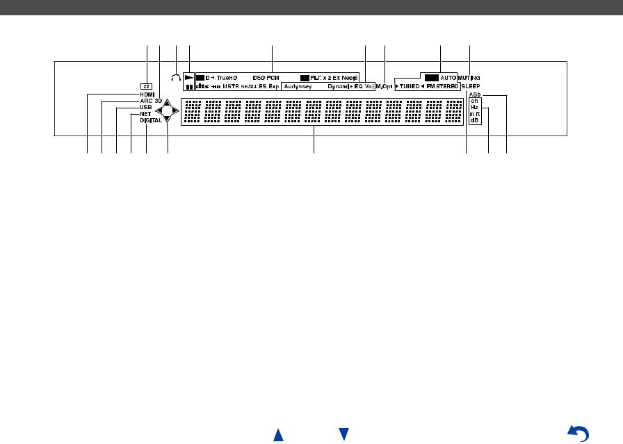
Display
ab cd |
e |
f g |
h |
i |
j k l m j d |
n |
|
|
o p q |
For detailed information, see the pages in parentheses.
a Z2 (Zone 2) indicator (70)
b3D indicator
This lights when a 3D input signal is detected.
c Headphone indicator (20)
d 1, 3and cursor indicators (32)
e Listening mode and format indicators (41, 62)
fAudyssey indicator (24, 58) Dynamic EQ indicator (59) Dynamic Vol indicator (59)
g M.Opt (Music Optimizer) indicator (50)
hTuning indicators
RDS indicator (excluding North American and Taiwanese models) (39)
AUTO indicator (38) TUNED indicator (38)
FM STEREO indicator (38)
i MUTING indicator (46)
jInput indicators (18) HDMI indicator (65) DIGITAL indicator
k ARC (Audio Return Channel) indicator (66) l USB indicator (32)
m NET indicator (32 to 36, 67) n Message area
o SLEEP indicator (45)
pChannel/Unit indicators ch indicator
Hz indicator m/ft indicator dB indicator
q ASb (Auto Standby) indicator (66)
En-9

|
|
|
|
|
|
|
|
|
|
|
|
|
|
|
|
|
|
|
|
|
|
|
|
|
|
|
|
|
|
|
|
|
|
|
|
|
|
|
|
|
|
|
|
|
|
|
|
|
|
|
|
|
|
|
|
|
Safety Information and Introduction |
||||||
|
|
|
|
|
|
|
|
|
|
|
|
|
|
|
|
|
|
|
|
|
|
|
|
|
|
|
|
|
|
|
|
|
|
|
|
|
|
|
|
|
|
|
|
|
|
|
|
|
|
|
|
|
|
|
|
|
|
|
|
|
|
|
|
Rear Panel |
|
|
|
|
|
|
|
|
|
|
|
|
|
|
|
|
|
|
|
|
|
|
|
|
|
|
|
|
|
|
|
|
|
|
|
|
|
|
|
|
|
|
|
|
|
|
|
|
|
|
|
|
|
|
|
|
|
|
|
|
|
||
(North American, European, Australian and Asian models) |
|
|
|
|
|
|
|
|
|
|
|
|
|
|
|
(Taiwanese models) |
|||||||||||||||||||||||||||||||||||||||||||||||
a |
b c d |
|
|
|
|
|
e |
|
|
|
|
|
|
|
|
|
|
|
f |
g |
|
|
|
|
|
|
|
|
|
|
|
|
|
|
n |
||||||||||||||||||||||||||||
|
|
|
|
|
|
|
|
|
|
|
|
|
|
|
|
|
|
|
|
|
|
|
|
|
|
|
|
|
|
|
|
|
|
|
|
|
|
|
|
|
|
|
|
|
|
|
|
|
|
|
|
|
|
|
|
|
|
|
|
|
|
|
|
|
|
|
|
|
|
|
|
|
|
|
|
|
|
|
|
|
|
|
|
|
|
|
|
|
|
|
|
|
|
|
|
|
|
|
|
|
|
|
|
|
|
|
|
|
|
|
|
|
|
|
|
|
|
|
|
|
|
|
|
|
|
|
|
|
|
|
|
|
|
|
|
|
|
|
|
|
|
|
|
|
|
|
|
|
|
|
|
|
|
|
|
|
|
|
|
|
|
|
|
|
|
|
|
|
|
|
|
|
|
|
|
|
|
|
|
|
|
|
|
|
|
|
|
|
|
|
|
|
|
|
|
|
|
|
|
|
|
|
|
|
|
|
|
|
|
|
|
|
|
|
|
|
|
|
|
|
|
|
|
|
|
|
|
|
|
|
|
|
|
|
|
|
|
|
|
|
|
|
|
|
|
|
|
|
|
|
|
|
|
|
|
|
|
|
|
|
|
|
|
|
|
|
|
|
|
|
|
|
|
|
|
|
|
|
|
|
|
|
|
|
|
|
|
|
|
|
|
|
|
|
|
|
|
|
|
|
|
|
|
|
|
|
|
|
|
|
|
|
|
|
|
|
|
|
|
|
|
|
|
|
|
|
|
|
|
|
|
|
|
|
|
|
|
|
|
|
|
|
|
|
|
|
|
|
|
|
|
|
|
|
|
|
|
|
|
|
|
|
|
|
|
|
|
|
|
|
|
|
|
|
|
|
|
|
|
|
|
|
|
|
|
|
|
|
|
|
|
|
|
|
|
|
|
|
|
|
|
|
|
|
|
|
|
|
|
|
|
|
|
|
|
|
|
|
|
|
|
|
|
|
|
|
|
|
|
|
|
|
|
|
|
|
|
|
|
|
|
|
|
|
|
|
|
hi |
j |
k |
lm |
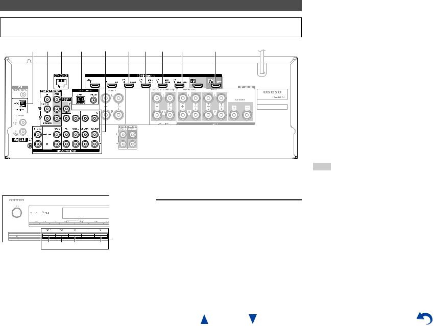
See “Connecting Your Speakers” for connection ( pages 12 to 20).
a u REMOTE CONTROL jack
b COMPONENT VIDEO IN and OUT jacks c ETHERNET port
d FM ANTENNA jack and AM ANTENNA terminal
eHDMI IN and HDMI output (HDMI OUT MAIN and HDMI OUT SUB) jacks
fSPEAKERS terminals
(CENTER, FRONT, SURROUND, SURROUND BACK or FRONT HIGH, ZONE 2)
gPower cord (North American, European, Australian and Asian models)
h DIGITAL IN COAXIAL and OPTICAL jacks i GND screw
jComposite video and analog audio jacks (BD/DVD IN, CBL/SAT IN, GAME IN, PC IN, TV/CD IN, PHONO IN)
k MONITOR OUT V jack l ZONE 2 LINE OUT jacks
m SUBWOOFER PRE OUT jacks n AC INLET (Taiwanese models)
En-10
Remote Controller
Controlling the AV Receiver
To control the AV receiver, press RECEIVER to select Receiver mode.
a*2 b*2
*1


RECEIVER |
g*2 |
|
hc |
|
i*2 |


 d ac
d ac


d


 j
j  k
k
e


e
bf


 l
l
For detailed information, see the pages in parentheses.
a 8RECEIVER button (21)
bREMOTE MODE/INPUT SELECTOR buttons (29)
c q/w/e/rand ENTER buttons d Q SETUP button (48)
e Listening Mode buttons (41) f DIMMER button (46)
g MUTING button (46) h DISPLAY button (45) i VOL q/wbutton (29) j RETURN button
k HOME button (47) l SLEEP button (45)
Tip
•You can also use the remote controller to control Onkyo Blu-ray Disc/DVD player, CD player, and other components.
See “Entering Remote Control Codes” for more details ( page 71).
■Controlling the tuner
To control the AV receiver’s tuner, press TUNER (or
RECEIVER).
You can select AM or FM by pressing TUNER repeatedly.
a q/wbuttons (38) b D.TUN button (38) c DISPLAY button d CH +/– button (39)
e Number buttons (38)
En-11
Safety Information and Introduction
*1 To control a component, you must first enter the remote control code.
See “Entering Remote Control Codes” for more details ( page 71).
*2 These buttons can also be used when a REMOTE MODE other than Receiver mode is selected.
■Aiming the remote controller
To use the remote controller, point it at the AV receiver’s remote control sensor, as shown below.
Remote control sensor
AV receiver
Approx. 16 ft. (5 m)
■Installing the batteries
Batteries (AA/R6)
Note
•If the remote controller doesn’t work reliably, try replacing the batteries.
•Don’t mix new and old batteries or different types of batteries.
•If you intend not to use the remote controller for a long time, remove the batteries to prevent damage from leakage or corrosion.
•Remove expired batteries as soon as possible to prevent damage from leakage or corrosion.
Connections
Connecting the AV
Receiver
Connecting Your Speakers
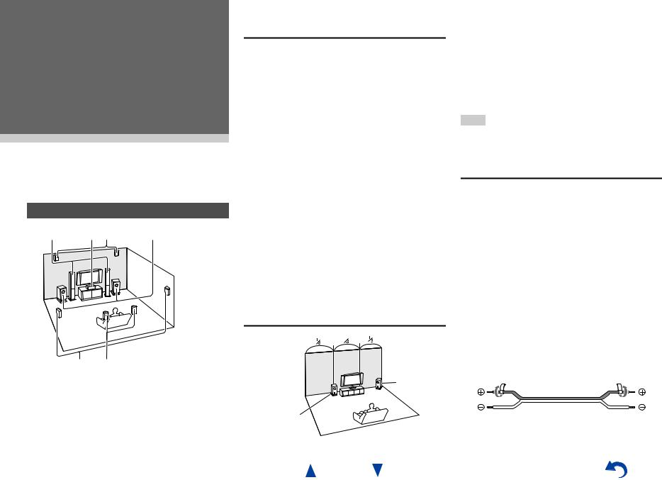
a b cI J |
f |
d e G H a b Front speakers
c |
Center speaker |
d e Surround speakers
fSubwoofer(s)
G H Surround back speakers
I J Front high speakers
Speaker Configuration
The following table indicates the channels you should use depending on the number of speakers that you have.
No matter how many speakers you use, a powered subwoofer is recommended for a really powerful and solid bass.
To get the best from your surround sound system, you need to set the speaker settings automatically ( page 24) or manually ( page 55).
Number of speakers |
2 |
3 |
4 |
5 |
6 |
7 |
7 |
Front speakers |
|
|
|
|
|
|
|
|
|
|
|
|
|
|
|
Center speaker |
|
|
|
|
|
|
|
|
|
|
|
|
|
|
|
Surround speakers |
|
|
|
|
|
|
|
|
|
|
|
|
|
|
|
Surround back speaker*1 |
|
|
|
|
|
|
|
Surround back speakers*1 |
|
|
|
|
|
|
|
Front high speakers*1 |
|
|
|
|
|
|
|
Speaker Configuration 5.1-channel: a b c d e f
7.1-channel: a b c d e f + G H
7.1-channel: a b c d e f + I J
*1 Front high and surround back speakers cannot be used at the same time.
Using Powered Subwoofers
Corner position
1/3 of wall position
En-12
Connections
To find the best position for your subwoofer, while playing a movie or some music with good bass, experiment by placing your subwoofer at various positions within the room, and choose the one that provides the most satisfying results.
You can connect the powered subwoofer with two SUBWOOFER PRE OUT jacks respectively.
The same signal is output from each jack.
Tip
•If your subwoofer is unpowered and you’re using an external amplifier, connect the subwoofer pre out jack to an input on the amplifier.
Attaching the Speaker Cable Labels
The speaker terminals are color-coded for identification purpose.
Speaker |
Color |
Front left, Front high left, Zone 2 left |
White |
|
|
Front right, Front high right, Zone 2 |
Red |
right |
|
|
|
Center |
Green |
|
|
Surround left |
Blue |
|
|
Surround right |
Gray |
|
|
Surround back left |
Brown |
|
|
Surround back right |
Tan |
|
|
The supplied speaker cable labels are also colorcoded and you should attach them to the positive (+) side of each speaker cable in accordance with the table above. Then all you need to do is to match the color of each label to the corresponding speaker terminal.
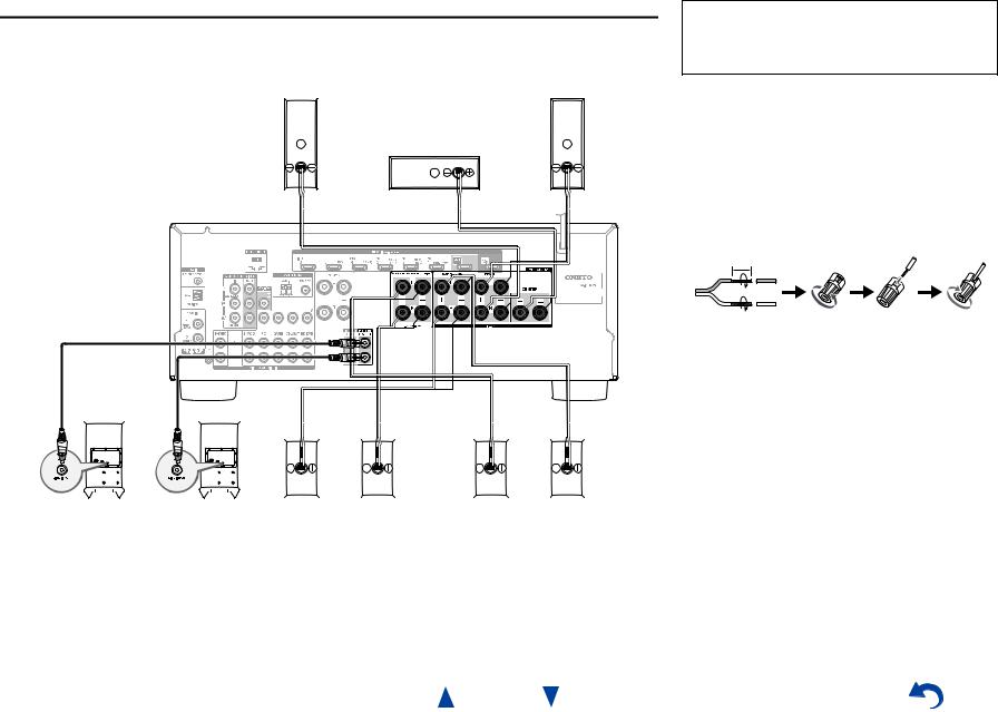
Connecting the Speaker Cables/Powered Subwoofers
Please connect a , b , c , d , e and f for 5.1-channel surround.
If you’re using only one surround back speaker, connect it to the SURROUND BACK or FRONT HIGH L terminals.
b |
a |
Front |
Front |
speaker R |
speaker L |
|
c |
|
Center speaker |
|
|
|
|
|
|
|
|
|
|
|
|
|
|
|
|
|
|
|
|
|
|
|
|
|
|
|
|
|
|
|
|
|
|
Red |
|
|
|
|
|
Green |
|
|
|
|
|
|
White |
|||||||||||||||||||||||||||
|
|
|
|
|
|
|
|
|
|
|
|
|
|
|
|
|
|
|
|
|
|
|
|
|
|
|
|
|
|
|
|
|
|
|
|
|
|
|
|
|
|
|||||||||||||||||||||||||||||||||
|
|
|
|
|
|
|
|
|
|
|
|
|
|
|
|
|
|
|
|
|
|
|
|
|
|
|
|
|
|
|
|
|
|
|
|
|
|
|
|
|
|
|
|
|
|
|
|
|
|
|
|
|
|
|
|
|
|
|
|
|
|
|
|
|
|
|
|
|
|
|
|
|
|
|
|
|
|
|
|
|
|
|
|
|
|
|
|
|
|
|
|
|
|
|
|
|
|
|
|
|
|
|
|
|
|
|
|
|
|
|
|
|
|
|
|
|
|
|
|
|
|
|
|
|
|
|
|
|
|
|
|
|
|
|
|
|
|
|
|
|
|
|
|
|
|
|
|
|
|
|
|
|
|
|
|
|
|
|
|
|
|
|
|
|
|
|
|
|
|
|
|
|
|
|
|
|
|
|
|
|
|
|
|
|
|
|
|
|
|
|
|
|
|
|
|
|
|
|
|
|
|
|
|
|
|
|
|
|
|
|
|
|
|
|
|
|
|
|
|
|
|
|
|
|
|
|
|
|
|
|
|
|
|
|
|
|
|
|
|
|
|
|
|
|
|
|
|
|
|
|
|
|
|
|
|
|
|
|
|
|
|
|
|
|
|
|
|
|
|
|
|
|
|
|
|
|
|
|
|
|
|
|
|
|
|
|
|
|
|
|
|
|
|
|
|
|
|
|
|
|
|
|
|
|
|
|
|
|
|
|
|
|
|
|
|
|
|
|
|
|
|
|
|
|
|
|
|
|
|
|
|
|
|
|
|
|
|
|
|
|
|
|
|
|
|
|
|
|
|
|
|
|
|
|
|
|
|
|
|
|
|
|
|
|
|
|
|
|
|
|
|
|
|
|
|
|
|
|
|
|
|
|
|
|
|
|
|
|
|
|
|
|
|
|
|
|
|
|
|
|
|
|
|
|
|
|
|
|
|
|
|
|
|
|
|
|
|
|
|
|
|
|
|
|
|
|
|
|
|
|
|
|
|
|
|
|
|
|
|
|
|
|
|
|
|
|
|
|
|
|
|
|
|
|
|
|
|
|
|
|
|
|
|
|
|
|
|
|
|
|
|
|
|
|
|
|
|
|
|
|
|
|
|
|
|
|
|
|
|
|
|
|
|
|
|
|
|
|
|
|
|
|
|
|
|
|
|
|
|
|
|
|
|
|
|
|
|
|
|
|
|
|
|
|
|
|
|
|
|
|
|
|
|
|
|
|
|
|
|
|
|
|
|
|
|
|
|
|
|
|
|
|
|
|
|
|
|
|
|
|
|
|
|
|
|
|
|
|
|
|
|
|
|
|
|
|
|
|
|
|
|
|
|
|
|
|
|
|
|
|
|
|
|
|
|
|
|
|
|
|
|
|
|
|
|
|
|
|
|
|
|
|
|
|
|
|
|
|
|
|
|
|
|
|
|
|
|
|
|
|
|
|
|
|
|
|
|
|
|
|
|
|
|
|
|
|
|
|
|
|
|
|
|
|
|
|
|
|
|
|
|
|
|
|
|
|
|
|
|
|
|
|
|
|
|
|
|
|
|
|
|
|
|
|
|
|
|
|
|
|
|
|
|
|
|
|
|
|
|
|
|
|
|
|
|
|
|
|
|
|
|
|
|
|
|
|
|
|
|
|
|
|
|
|
|
|
|
|
|
|
|
|
|
|
|
|
|
|
|
|
|
|
|
|
|
|
|
|
|
|
|
|
|
|
|
|
|
|
|
|
|
|
|
|
|
|
|
|
|
|
|
|
|
|
|
|
|
|
|
|
|
|
|
|
|
|
|
|
|
|
|
|
|
|
|
|
|
|
|
|
|
|
|
|
|
|
|
|
|
|
|
|
|
|
|
|
|
|
|
|
|
|
|
|
|
|
|
|
|
|
|
|
|
|
|
|
Gray |
|
|
|
|
Tan |
|
|
|
|
Brown |
|
|
|
|
Blue |
||||
|
|
|
|
|
|
|
|
|
|
|
|
|
|
|
|
|
|
|
|
|
|
|
|
|
|
|
|
|
|
|
|
|
|
|
|
|
|
|
|
|
|
|
|
|
|
|
|
|
|
|
|
|
|
|
|
|
|
|
|
|
|
|
|
|
|
|
|
|
|
|
|
|
|
|
|
|
|
|
|
|
|
|
|
|
|
|
|
|
|
|
|
|
|
|
|
|
|
|
|
|
|
|
|
|
|
|
|
|
|
|
|
|
|
|
|
|
|
|
|
|
|
|
|
|
|
|
|
|
|
|
|
|
|
|
|
|
|
|
|
|
|
|
|
|
|
|
|
|
|
|
|
|
|
|
|
|
|
|
|
Powered |
Powered |
Surround |
Surround back or |
Surround back or |
Surround |
subwoofer |
subwoofer |
speaker R |
Front high speaker R |
Front high speaker L |
speaker L |
f |
f |
e |
H J |
G I |
d |
•Pay close attention to speaker wiring polarity. In other words, connect positive (+) terminals only to positive (+) terminals, and negative (–) terminals only to negative (–) terminals. If you get them the wrong way around, the sound will be out of phase and will sound unnatural.
Connections
Before connecting the power cord, connect all of your speakers and AV components. A setup wizard is launched upon first-time use to let you perform the settings.
•Read the instructions supplied with your speakers.
•By default, speakers for 7.1-channel surround are configured to use: front right/front left/center/ surround right/surround left/surround back right/ surround back left/subwoofer.
■Screw-type speaker terminals
Strip 1/2" to 5/8" (12 to 15 mm) of insulation from the ends of the speaker cables, and twist the bare wires tightly, as shown.
1/2" to 5/8" (12 to 15 mm)
■Banana Plugs (North American models)
•If you are using banana plugs, tighten the speaker terminal before inserting the banana plug.
•Do not insert the speaker code directly into the center hole of the speaker terminal.
En-13
Speaker Connection Precautions
•(North American and Taiwanese models) You can connect speakers with an impedance of between 6 and 16 ohms. If you use speakers with a lower impedance, and use the amplifier at high volume levels for a long period of time, the built-in amp protection circuit may be activated.
•(European, Australian and Asian models) You can connect speakers with an impedance of between 4 and 16 ohms. If the impedance of any of the connected speakers is 4 ohms or more, but less than 6 ohms, be sure to set the minimum speaker impedance to “4ohms” ( page 55). If you use speakers with a lower impedance, and use the amplifier at high volume levels for a long period of time, the built-in protection circuit may be activated.
•Unnecessarily long, or very thin speaker cables may affect the sound quality and should be avoided.
•Be careful not to short the positive and negative wires. Doing so may damage the AV receiver.
•Make sure the metal core of the wire does not have contact with the AV receiver’s rear panel. Doing so may damage the AV receiver.
•Don’t connect more than one cable to each speaker terminal. Doing so may damage the AV receiver.
•Don’t connect one speaker to several terminals.
Connections
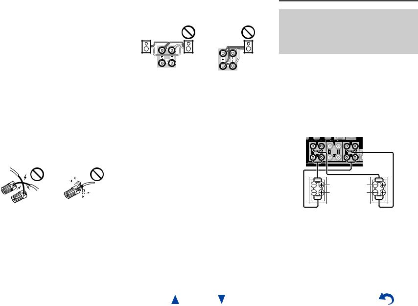
Bi-amping the Front Speakers
Important:
•When making the bi-amping connections, be sure to remove the jumper bars that link the speakers’ tweeter (high) and woofer (low) terminals.
•Bi-amping can be used only with speakers that support bi-amping. Refer to your speaker manual.
Bi-amping provides improved bass and treble performance.
When bi-amping is used, the AV receiver is able to drive up to a 5.1 speaker system in the main room. Perform bi-amping connections by using FRONT terminals and SURROUND BACK or FRONT HIGH terminals as shown below.
Once you’ve completed the bi-amping connections and turned on the AV receiver, you must set the speaker setting to enable bi-amping ( page 55).
Tweeter (high) |
Woofer (low) |
Front right |
Front left |
En-14
Connecting the TV/AV components
Before connecting the power cord, connect all of your speakers and AV components. To display the setup menu on the TV screen, connecting the TV to HDMI OUT MAIN is required.
E I F G H D C B J A
Connections
CUse this jack to connect to the Satellite/cable settop box, etc.
DUse this jack to connect to the game consoles, etc.
FUse this port to connect to a LAN port on a router so the AV receiver can be connected to your home network.
GUse jack and terminal here to connect the supplied FM antenna and AM loop antenna.
HUse this jack to make connections using an analog audio cable.
With this connection, you can also enjoy analog audio from external components while you are in Zone 2.
IUse this jack to make connections using a component video cable.
JUse this jack to connect to the camcorder/MHLenabled mobile device, etc.
If you select the input selector button, the signal from the component connected to the assigned jack is played.
|
|
|
|
Input |
B |
C |
D |
J |
selector |
|
|
|
|
buttons |
•Before making any AV connections, read the manuals supplied with your AV components.
•Push plugs in all the way to make good connections (loose connections can cause noise or malfunctions).
•To prevent interference, keep audio and video cables away from power cords and speaker cables.
Connections
AUse this jack to connect to the HDMI input of the TV. If your TV doesn’t support Audio Return Channel (ARC)*1, you need to connect an optical digital cable together with the HDMI cable to jack
E.
Another TV can be connected to the HDMI OUT SUB jack.
*1 ARC is the function that carries the audio signal from the TV to jack A. With ARC, a single HDMI cable can connect the TV and the AV receiver.
BUse this jack to connect to your Blu-ray Disc/DVD player, etc.
En-15
Tip
•To listen to the audio of a component connected via HDMI through your TV’s speakers, enable “HDMI Through”
( page 65) and set the AV receiver to standby mode.
•In the case of Blu-ray Disc/DVD players, if no sound is output despite following the above-mentioned procedure, set your Blu-ray Disc/DVD player’s HDMI audio settings to PCM.
•Connect a turntable (MM) that has a built-in phono preamp to TV/CD IN, or connect it to PHONO IN with the phono preamp turned off. If your turntable (MM) doesn’t have a phono preamp, connect it to PHONO IN. If your turntable has a moving coil (MC) type cartridge, you’ll need a commercially available MC head amp or MC transformer to connect to PHONO IN. See your turntable’s manual for details.
If your turntable has a ground wire, connect it to the AV receiver’s GND screw. With some turntables, connecting the ground wire may produce an audible hum. If this happens, disconnect it.
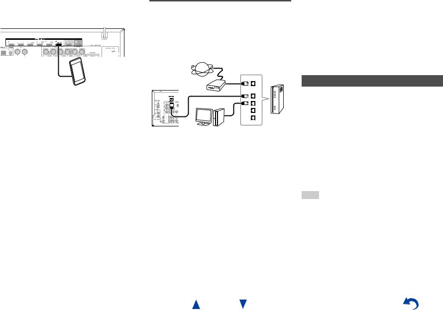
■MHL (Mobile High-Definition Link)
With its support for MHL (Mobile High-Definition Link), HDMI IN 1 allows you to deliver high-definition video from a connected mobile device.
MHL-enabled mobile device, etc.
Connecting to the Network (Optional)
The following diagram shows how you can connect the AV receiver to your home network. In this example, it’s connected to a LAN port on a router, which has a 4-port 100Base-TX switch built-in. Network connection by wireless LAN is possible. See “Performing Wireless LAN Setup” for connections ( page 27).
Internet radio
WAN Router
Modem
LAN
Computer or media server
Do not connect the AV receiver’s USB port to a USB port on your computer. Music on your computer cannot be played through the AV receiver in this way.
The default of the assignment for the input selector buttons and jacks are as shown below. These settings can be changed. (The assignment for the composite video jacks and the analog audio jacks cannot be changed.)
Input selector buttons |
HDMI jacks |
COMPONENT VIDEO |
DIGITAL IN COAXIAL |
Composite video and |
|
|
jacks |
and OPTICAL jacks |
analog audio jacks |
BD/DVD |
HDMI IN 2 |
|
DIGITAL IN |
VIDEO/AUDIO IN |
|
|
|
COAXIAL 1 |
BD/DVD |
|
|
|
|
|
CBL/SAT |
HDMI IN 3 |
COMPONENT VIDEO |
DIGITAL IN |
VIDEO/AUDIO IN |
|
|
IN |
COAXIAL 2 |
CBL/SAT |
|
|
|
|
|
GAME |
HDMI IN 4 |
|
|
VIDEO/AUDIO IN |
|
|
|
|
GAME |
|
|
|
|
|
PC |
HDMI IN 5 |
|
|
VIDEO/AUDIO IN PC |
|
|
|
|
|
AUX |
HDMI IN 1 |
|
|
VIDEO/AUDIO IN AUX |
|
|
|
|
|
TV/CD |
|
|
DIGITAL IN OPTICAL |
AUDIO IN TV/CD |
|
|
|
|
|
PHONO |
|
|
|
AUDIO IN PHONO |
|
|
|
|
|
En-16
Connections
p
The AV receiver allows interoperability of the CEC (Consumer Electronics Control) specified in the HDMI standard, which is known as RIHD. Various linked operations can be performed by connecting the AV receiver to an RIHD-compatible TV, player, or recorder.
Default setting is set to off, so it is required to change the setting to on.
Perform this setting after the initial setup.
About RIHD-compatible components
The following components are p-compatible (As of January 2013).
■TV
• Sharp TV
■Players/Recorders
•Onkyo and Integra p-compatible players
•Toshiba players and recorders
•Sharp players and recorders (only when used together with Sharp TV)
*Models other than those mentioned above may have some interoperability if compatible with CEC, which is part of the HDMI Standard, but operation cannot be guaranteed.
Note
•For proper linked operations, do not connect more p-compatible components than the quantities specified below, to the HDMI input terminal.
–Blu-ray Disc/DVD players: up to three.
–Blu-ray Disc/DVD recorders/Digital Video Recorders: up to three.
–Cable/Satellite Set-top boxes: up to four.
•Do not connect the AV receiver to another AV receiver/AV amplifier via HDMI.
•Proper linked operations are not guaranteed when more p-compatible components than the abovementioned quantities are connected.

Operations that can be performed with RIHD connection
■For p-compatible TV
The following linked operations are enabled by connecting the AV receiver to an p-compatible TV.
•The AV receiver will enter standby mode when the TV is set to standby.
•You can set on the menu screen of the TV to either output the audio from the speakers connected to the AV receiver, or from the speakers of the TV.
•It is possible to output the audio coming from the tuner or auxiliary input of your TV to the speakers of the AV receiver. (A connection such as an optical digital cable or similar is required in addition to the HDMI cable.)
•Input to the AV receiver can be selected with the remote controller of the TV.
•Operations such as volume adjustment or similar for the AV receiver can be performed from the remote controller of the TV.
■For p-compatible players/recorders
The following linked operations are enabled by connecting the AV receiver to an p-compatible player/recorder.
•When playback is started on the player/recorder, AV receiver will switch to the HDMI input of the player/recorder that is playing back.
•Operation of the player/recorder is possible using the remote controller supplied with the AV receiver.
*Depending on the model used, not all operations may be available.
Note
•Do not assign an HDMI IN to the TV/CD selector at this time, otherwise appropriate CEC (Consumer Electronics Control) operation will not be guaranteed.
Confirm the settings
1.Turn on the power for all connected components.
2.Turn off the power of the TV, and confirm that the power of the connected components is turned off automatically with the link operation.
3.Turn on the power of the Blu-ray Disc/DVD player/recorder.
4.Start playback on the Blu-ray Disc/DVD player/recorder, and verify the following:
•The AV receiver automatically turns on, and selects the input to which the Blu-ray Disc/DVD player/recorder is connected.
•The TV automatically turns on, and selects the input to which the AV receiver is connected.
5.Following the operating instructions of the TV, select “Use the TV speakers” from the menu screen of the TV, and confirm that the audio is output from the speakers of the TV, and not from the speakers connected to the AV receiver.
6.Select “Use the speakers connected from the AV receiver” from the menu screen of the TV, and confirm that the audio is output from the speakers connected to the AV receiver, and not from the TV speakers.
Note
•Audio from DVD-Audio or Super Audio CD may not output from the TV speakers. You will be able to output the audio from the TV speakers by setting the audio output of the DVD player to 2ch PCM. (It may not be possible depending on the player models.)
•Even if you set to output audio on the TV speakers, audio will be output from the speakers connected to the AV receiver when you adjust the volume or switch the input on the AV receiver. To output audio from the TV speakers, redo the corresponding operations on the TV.
•In case of an pconnection with uand uaudio control compatible components, do not connect the u cable at the same time.
En-17
Connections
•On the TV, when you select anything other than the HDMI jack to which the AV receiver is connected, the input on the AV receiver will be switched to “TV/CD”.
•The AV receiver will automatically power on in conjunction when it determines it to be necessary. Even if the AV receiver is connected to an pcompatible TV or player/recorder, it will not power on if it is not necessary. It may not power on in conjunction when the TV is set to output audio from the TV.
•Linked functions with the AV receiver may not work depending on the component model connected. In such cases, operate the AV receiver directly.
Connection Tips
The video and audio signal flow
Connect the AV receiver between the AV components and the TV. The signal from the AV components is carried through the AV receiver. You can enjoy the audio of the TV through the AV receiver.
Blu-ray Disc/DVD player, etc.
Video, audio
AV receiver
Audio |
|
|
Video, audio |
|
|
|
|
|
|
|
|
|
|
|
|
|
|
|
|
TV, projector, etc.
Video components can be connected by using any one of the following video connection formats: composite video, component video, or HDMI, the latter offering the best picture quality.
Video input signals flow through the AV receiver as shown, with composite video and component video sources all being upconverted for the HDMI output(s).
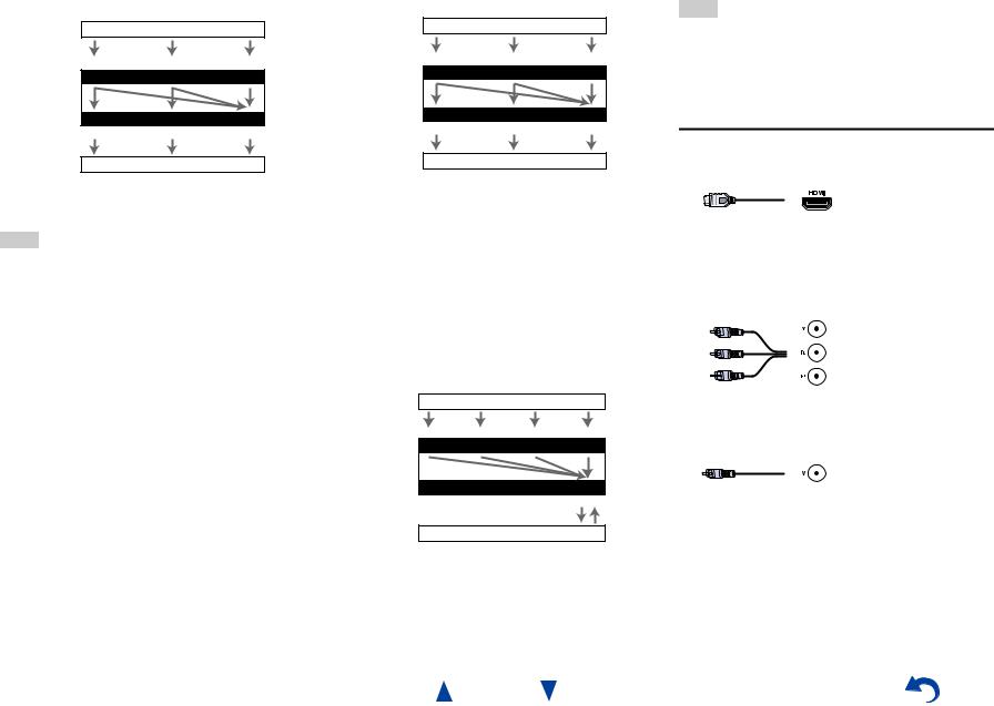
Video Signal Flow Chart
Blu-ray Disc/DVD player, etc.
Composite |
Component |
HDMI |
|
IN |
|
AV receiver |
|
|
|
MONITOR OUT |
|
Composite |
Component |
HDMI |
TV, projector, etc.
The composite video and component video outputs pass through their respective input signals as they are.
Note
•In order for the AV receiver to upconvert component input to HDMI output, the source output must be set to 480i/576i. When signal is input at resolution of 480p/576p and more, error message will be displayed.
■Signal Selection
If signals are present at more than one input, the inputs will be selected automatically in the following order of priority: HDMI, component video, composite video.
However, for component video only, regardless of whether a component video signal is actually present, if a component video input is assigned to the input selector, that component video input will be selected. And if no component video input is assigned to the input selector, this will be interpreted as no component video signal being present.
In the Signal Selection Example shown below, video signals are present at both the HDMI and composite video inputs. However, the HDMI signal is automatically selected as the source and the video is output by the HDMI outputs.
Signal Selection Example |
||
Blu-ray Disc/DVD player, etc. |
||
Composite |
Component |
HDMI |
|
IN |
|
AV receiver |
|
|
|
MONITOR OUT |
|
Composite |
Component |
HDMI |
TV, projector, etc.
•To by-pass the upconversion, set the “Picture Mode” setting to “Bypass” ( page 61).
Audio components can be connected by using any of the following audio connection formats: analog, optical, coaxial, or HDMI.
When choosing a connection format, bear in mind that the AV receiver does not convert digital input signals for analog line outputs and vice versa.
If signals are present at more than one input, the inputs will be selected automatically in the following order of priority: HDMI, digital, analog.
Audio Signal Flow Chart
Blu-ray Disc/DVD player, etc.
|
Analog |
Optical |
Coaxial |
|
HDMI |
|
|
|
IN |
|
|
AV receiver |
*1 |
|
*1 |
*1 |
|
|
|
|
|
||
|
|
|
OUT |
|
|
|
|
|
|
|
HDMI |
|
|
|
|
*1 |
*2 |
TV, projector, etc.
*1 Depends on the “Audio TV Out (Main)” or “Audio TV Out (Sub)” setting ( page 65).
*2 This is possible when “Audio Return Channel” is set to “Auto” ( page 66), the TV/CD input selector is selected, and your TV is ARC capable.
Connections
Tip
•When a signal is input via HDMI and the corresponding input selector is selected, the HDMI indicator lights. In the case of an optical or coaxial connection, the DIGITAL indicator lights. In the case of an analog connection, neither of the HDMI and DIGITAL indicators light.
AV Cables and Jacks
■HDMI
HDMI connections can carry digital video and audio.
■Component video
Component video separates the luminance (Y) and color difference signals (PB, PR), providing the best picture quality (some TV manufacturers label their component video sockets slightly differently).
Y |
Green |
CB/PB |
Blue |
CR/PR |
Red |
■Composite video
Composite video is commonly used on TVs, DVDs, and other video equipment.
Yellow
En-18
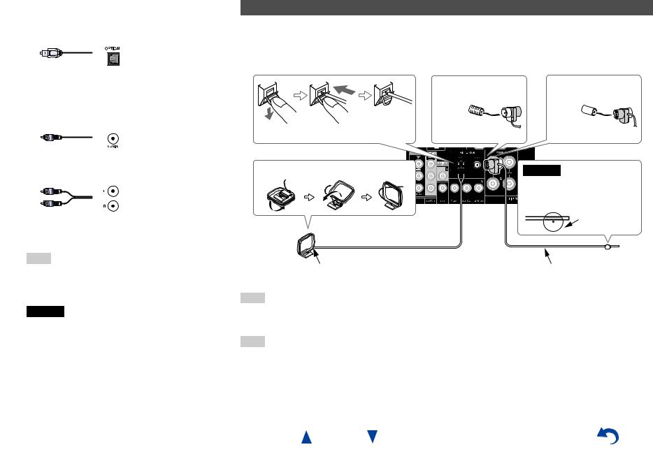
■Optical digital audio
Optical digital connections allow you to enjoy digital sound such as PCM*1, Dolby Digital or DTS. The audio quality is the same as coaxial.
Connections
Connecting the Antennas
This section explains how to connect the supplied indoor FM antenna and AM loop antenna.
The AV receiver won’t pick up any radio signals without any antenna connected, so you must connect the antenna to use the tuner.
■Coaxial digital audio
Coaxial digital connections allow you to enjoy digital sound such as PCM*1, Dolby Digital or DTS. The audio quality is the same as optical.
Orange
■Analog audio (RCA)
Analog audio connections (RCA) carry analog audio.
White
Red
*1 For PCM signals, the supported sampling rates are 32/44.1/48/88.2/96 kHz. With HDMI connections, 176.4 and 192 kHz are also supported.
Note
•The AV receiver does not support SCART plugs.
•The AV receiver’s optical digital jacks have shutter-type covers that open when an optical plug is inserted and close when it’s removed. Push plugs in all the way.
Caution
•To prevent shutter damage, hold the optical plug straight when inserting and removing.
|
|
|
(North American and |
(European, Australian |
|
|
|
|
Taiwanese models) |
and Asian models) |
|
Push. |
Insert wire. |
Release. |
Insert the plug fully |
Insert the plug fully |
|
into the jack. |
into the jack. |
||||
|
|
|
|||
Assembling the AM loop antenna |
|
Caution |
|||
• Be careful not to injure yourself when using


 thumbtacks.
Thumbtacks, etc.
AM loop antenna (supplied) |
Indoor FM antenna (supplied) |
Note
•Once your AV receiver is ready for use, you’ll need to tune into a radio station and position the antenna to achieve the best possible reception.
•Keep the AM loop antenna as far away as possible from your AV receiver, TV, speaker cables, and power cords.
Tip
•If you cannot achieve good reception with the supplied indoor FM antenna, try a commercially available outdoor FM antenna instead.
•If you cannot achieve good reception with the supplied indoor AM loop antenna, try using it with a commercially available outdoor AM antenna.
En-19
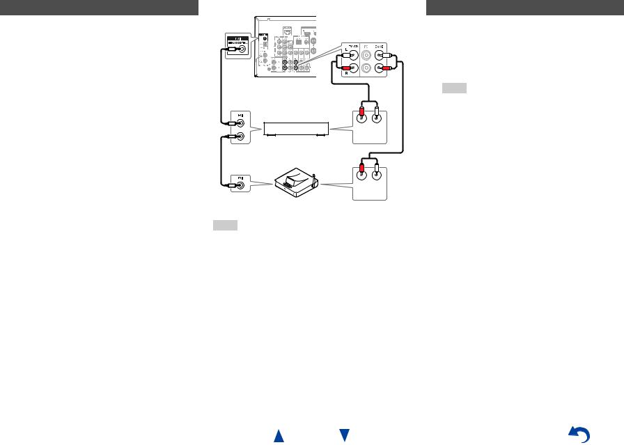
Connecting Onkyo RI Components
1 |
Make sure that each Onkyo component is |
|
connected with an analog audio cable |
|
(connection H in the hookup examples) |
|
( page 15). |
2 |
Make the uconnection (see the illustration). |
3 |
If you’re using an RI Dock, or cassette tape |
|
deck, change the Input Display ( page 46). |
With u(Remote Interactive), you can use the following special functions:
System On/Auto Power On
When you start playback on a component connected via u, while the AV receiver is on standby, the AV receiver will automatically turn on and select that component as the input source.
Direct Change
When playback is started on a component connected via u, the AV receiver automatically selects that component as the input source.
Remote Control
You can use the AV receiver’s remote controller to control your other u-capable Onkyo components, pointing the remote controller at the AV receiver’s remote control sensor instead of the component. You must enter the appropriate remote control code first ( page 72).
R L
ANALOG
AUDIO OUT
e.g., cassette tape deck
R L
ANALOG
AUDIO OUT
RI Dock
Note
•Use only ucables for uconnections. ucables are supplied with Onkyo components.
•Some components have two ujacks. You can connect either one to the AV receiver. The other jack is for connecting additional u-capable components.
•Connect only Onkyo components to ujacks. Connecting other manufacturer’s components may cause a malfunction.
•Some components may not support all ufunctions. Refer to the manuals supplied with your Onkyo components.
•While Zone 2 is on, the System On/Auto Power On and Direct Change ufunctions do not work.
Connections
Using Headphones
1 Connect a pair of stereo headphones with a standard plug (1/4 inch or ø 6.3 mm) to the PHONES jack.
While the headphones plug is inserted in the PHONES jack, =indicator lights.
Note
•Always turn down the volume before connecting your headphones.
•While the headphones plug is inserted in the PHONES jack, the speakers are turned off. (The Zone 2 speakers are not turned off.)
•When you connect a pair of headphones, the listening mode is set to Stereo, unless it’s already set to Stereo, Mono, Direct, or Pure Audio (European, Australian and Asian models).
En-20
Turning On & Basic
Operations
the same circuit. If this is a problem, plug the AV receiver into a different branch circuit.
•Do not use a power cord other than the one supplied with the AV receiver. The supplied power cord is designed exclusively for use with the AV receiver and should not be used with any other equipment.
•Never disconnect the power cord from the AV receiver while the other end is still plugged into a wall outlet. Doing so may cause an electric shock. Always disconnect the power cord from the wall outlet first, and then the AV receiver.
Turning On/Off the AV
Receiver
Connecting the Power Cord
1 (Taiwanese models)
Connect the supplied power cord to the AV receiver’s AC INLET.
To AC wall outlet
2 Plug the power cord into an AC wall outlet.
Turning On
1 Press 8ON/STANDBY on the front panel. or
Press RECEIVER followed by 8RECEIVER on the remote controller.
The AV receiver comes on and its display lights.
Smooth Operation in a Few Easy Steps (Initial Setup)
To ensure smooth operation, here’s a few easy steps to help you configure the AV receiver before you use it for the very first time. These settings only need to be made once. See “Initial Setup” for details
( page 22).
Note
•Before connecting the power cord, connect all of your speakers and AV components.
•Turning on the AV receiver may cause a momentary power surge that might interfere with other electrical equipment on
En-21
Turning On & Basic Operations
Turning Off
1 Press 8ON/STANDBY on the front panel. or
Press RECEIVER followed by 8RECEIVER on the remote controller.
The AV receiver will enter standby mode. To prevent any loud surprises when you turn on the AV receiver, always turn down the volume before you turn it off.
Tip
•The HYBRID STANDBY indicator may light depending on the status of settings ( page 22).
•For details on power management settings, see “Auto Standby” ( page 66).
•If the HDMI Through setting is not set in standby mode, an MHL-enabled mobile device cannot be charged even if it is connected.

Firmware Update Notification
When a new version of the firmware is available, the notification window “Firmware Update Available” pops up. This notification only appears when the AV receiver is connected to the Internet ( pages 16, 27). To perform the firmware update, follow the instructions on screen.
Use q/wand ENTER on the AV receiver or remote controller to select one of the options.
`Update Now:
Starts the firmware update.
Refer to “Firmware Update” ( page 85).
`Remind me Later:
The update notification will pop up again the next time you turn the AV receiver on.
`Never Remind me:
Disables the automatic update notification.
Tip
•The update notification window can be enabled or disabled in “Update Notice” ( page 67).
About the HYBRID STANDBY indicator
By way of optimized circuitry, this function reduces power consumption when the AV receiver is in standby mode. The HYBRID STANDBY indicator will light in either of the following conditions:
–“HDMI Through” is enabled (the HDMI indicator is off).
–“Network Standby” is enabled (the NET indicator is off).
Note
•If Zones are turned on or, if a mobile device connected to
HDMI IN 1 (MHL) is charging, the HYBRID STANDBY indicator won’t light.
Initial Setup
This section explains the settings that we recommend you to make before using the AV receiver for the very first time. A setup wizard is launched upon first-time use to let you perform those settings.
Tip
•The on-screen menus appear only on a TV that is connected to HDMI OUT MAIN.
Selecting the Language for the Onscreen Setup Menus
This step determines the language used for the onscreen setup menus. See “Language” in “OSD Setup” ( page 64).
Tip
•Pressing HOME will close the setup wizard. To restart the initial setup, select “Initial Setup” in the “Hardware Setup” menu ( page 68).
After selecting the language for on-screen setup menus, a welcome screen is displayed.
Initial Setup
Welcome to initial setup. Have you connected all the speakers and devices?
Before starting, please connect speakers and sources.
Now, would you like to start initial setup?
1st Step : Audyssey MultEQ: Auto Setup 2nd Step : Source Connection
3rd Step : Remote Mode Setup 4th Step : Network Connection
Yes
No
HOME Exit
Turning On & Basic Operations
1 Use q/won the AV receiver or remote controller to select one of the following options, and then press ENTER.
`Yes:
Continues to “Audyssey MultEQ: Auto Setup”.
`No:
Skips the settings and terminates the initial setup. The setup wizard goes to “Terminating the Initial Setup” ( page 23). You can always restart the initial setup by selecting “Initial Setup” in the “Hardware Setup” menu ( page 68).
Audyssey MultEQ: Auto Setup
This step performs the automatic speaker setup.
1 Use q/wto select one of the following options, and then press ENTER.
`Do it Now:
The automatic speaker setup is performed following instructions on screen. Refer to step 2 of “Using the Automatic Speaker Setup” ( page 24). When this setting is complete, the setup wizard continues to “Source Connection”.
`Do it Later:
Skips this setting.
Press ENTER and continue to “Source Connection”.
En-22

Source Connection
This step checks the connection of source components.
1 Use q/wto select one of the following options, and then press ENTER.
`Yes, Continue: Performs the checkings.
`No, Skip:
Skips this step and continues to “Remote Mode Setup”.
2 Select the input selector for which you want to check the connection and press ENTER.
The picture and sound of the corresponding source should appear on screen with a verification prompt.
3 When prompted, use q/wto select one of the following options and then press ENTER.
`Yes:
Confirms that the source is properly displayed.
`No:
Displays an error report. Follow the troubleshooting instructions and recheck the source.
4 Use q/wto select one of the following options, and then press ENTER.
`Yes:
Returns to step 2.
`No, Done Checking:
The setup wizard continues to “Remote Mode Setup”.
Remote Mode Setup
With this step, you can enter remote control codes for the components you want to operate.
1 Use q/wto select one of the following options, and then press ENTER.
`Yes:
Performs the remote control code input. Refer to step 5 of “Looking up for Remote Control Codes” ( page 71).
`No, Skip:
Skips this step and continues to “Network Connection”.
2 When you’re finished, select one of the following options and press ENTER.
`Yes, Done:
The setup wizard continues to “Network Connection”.
`No, not yet:
You can enter other remote control codes.
Network Connection
This step checks your network connection.
1 Use q/wto select one of the following options, and then press ENTER.
`Yes:
Performs the checkings.
`No, Skip:
Skips this step and terminates the initial setup.
En-23
Turning On & Basic Operations
2 Follow the instructions on screen to perform the network checking.
The checking is complete when the message “Successfully connected.” appears at the middle of the screen. Press ENTER to terminate the initial setup.
Tip
•If you have selected “Wireless”, you need to perform the wireless LAN setup. See “Performing Wireless LAN Setup” ( page 27). This completes the initial setup.
3 If an error message appears, select one of the following options and press ENTER.
`Retry:
Performs the checking again.
`No, Do it Later:
Skips this step and terminates the initial setup. The setup wizard goes to “Terminating the Initial Setup”.
Terminating the Initial Setup
This step ends the initial setup process.
1 Press ENTER.
To restart the initial setup, select “Initial Setup” in the “Hardware Setup” menu ( page 68).
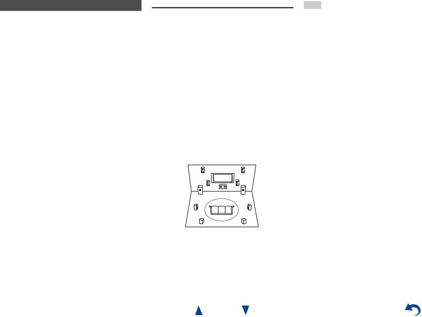
Using the Automatic Speaker Setup
With the supplied calibrated microphone, Audyssey MultEQ® automatically determines the number of speakers connected, their size for purposes of bass management, optimum crossover frequencies to the subwoofer (if present), and distances from the primary listening position.
Audyssey MultEQ then removes the distortion caused by room acoustics by capturing room acoustical problems over the listening area in both the frequency and time domain. The result is clear, well-balanced sound for everyone. Audyssey MultEQ can be used with Audyssey Dynamic EQ® and
Audyssey Dynamic Volume® ( page 59).
Before using this function, connect and position all of your speakers.
Audyssey MultEQ offers two ways of measuring: the “Audyssey Quick Start” and “Audyssey MultEQ Full Calibration”.
•“Audyssey Quick Start” uses the measurement from one position to perform the speaker setting only.
•“Audyssey MultEQ Full Calibration” uses the measurement from six positions to correct room response in addition to the speaker setting.
The more positions are used in measuring, the better the listening environment will become. We recommend using a measurement from six positions to create the best listening environment.
The Quick Start takes 2 minutes and Full Calibration takes about 15 minutes.
Total measurement time varies depending on the number of speakers.
Measurement procedure
To create a listening environment in your home theater that all listeners will enjoy, Audyssey MultEQ takes measurements at up to six positions within the listening area. Position the microphone at ear height of a seated listener with the microphone tip pointed directly at the ceiling using a tripod. Do not hold the microphone in your hand during measurements as this will produce inaccurate results.
■First measurement position
Also referred to as the Main Listening Position, this refers to the most central position where one would normally sit within the listening environment.
Audyssey MultEQ uses the measurements from this position to calculate speaker distance, level, and the optimum crossover value for the subwoofer.
■Second-sixth measurement positions
These are the other listening positions (i.e., the places where the other listeners will sit). You can measure up to six positions.
TV
d e f c a b
 : Listening area a to f: Listening position
Turning On & Basic Operations
Note
•Make the room as quiet as possible. Background noise and Radio Frequency Interference (RFI) can disrupt the room measurements. Close windows, televisions, radios, air conditioners, fluorescent lights, home appliances, light dimmers, or other devices. Turn off the cell phone (even if it is not in use) or place it away from all audio electronics.
•The microphone picks up test tones played through each speaker as Audyssey MultEQ Room Correction and Speaker Setup runs.
•Audyssey MultEQ Room Correction and Speaker Setup cannot be performed while a pair of headphones is connected.
En-24
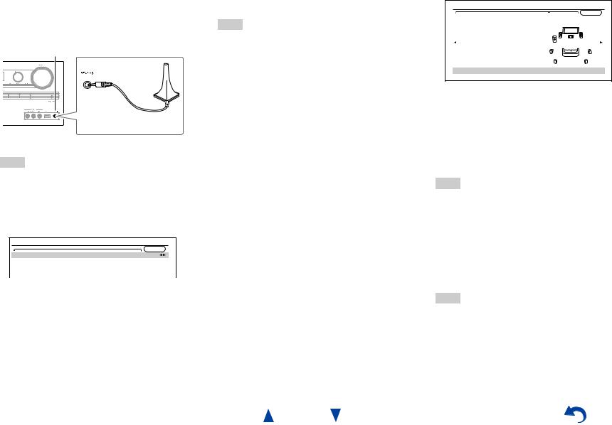
1 |
Turn on the AV receiver and the connected TV. |
|
On the TV, select the input to which the AV |
|
receiver is connected. |
2 |
Set the speaker setup microphone at the Main |
Listening Position a, and connect it to the
SETUP MIC jack.
SETUP MIC jack
Speaker setup microphone
The speaker setting menu appears.
Note
•The on-screen menus appear only on a TV that is connected to HDMI OUT MAIN. If your TV is connected to other video outputs, use the AV receiver’s display when changing settings.
3 When you’ve finished making the settings, press ENTER.
MultEQ: Auto Setup |
|
|
AUDYSSEY |
Speakers Type (Front) |
Normal |
Powered Zone 2 |
No |
Surround Back/Front High |
Surround Back |
Subwoofer |
Yes |
Perform the “2. Speaker Setup” according to your speaker configuration:
–Speakers Type (Front) ( page 55)
–Powered Zone 2 ( page 55)
–Surround Back/Front High ( page 56)
–Subwoofer ( page 56)
If you use a powered subwoofer(s), go to step 4. If not, go to step 5.
4 Adjust the subwoofer volume level to 75 dB, and then press ENTER.
Test tones are played through the subwoofer. Use the volume control on the subwoofer.
Note
•If your subwoofer does not have a volume control, disregard the displayed level and press ENTER to proceed to the next step.
•If you set the subwoofer’s volume control to its maximum and the level displayed is lower than 75 dB, leave the subwoofer’s volume control at its maximum and press ENTER to proceed to the next step.
5 Use q/wto select “Audyssey Quick Start” or
“Audyssey MultEQ Full Calibration”, and then press ENTER.
6 Press ENTER.
Audyssey MultEQ® Room Correction and Speaker Setup starts.
Test tones are played through each speaker as Audyssey MultEQ Room Correction and Speaker Setup runs. This process takes a few minutes. Please refrain from talking during measurements and do not stand between speakers and the microphone.
Do not disconnect the speaker setup microphone during Audyssey MultEQ Room Correction and Speaker Setup, unless you want to cancel the setup.
If you select “Audyssey Quick Start”, you will go to step 9.
7 Place the speaker setup microphone at the next position, and then press ENTER.
Audyssey MultEQ performs more measurements. This takes a few minutes.
8 When prompted, repeat step 7.
En-25
Turning On & Basic Operations
9 Use q/wto select an option, and then press
ENTER. |
|
MultEQ: Auto Setup |
|
|
AUDYSSEY |
|
-- Review Speaker Configuration -- |
Subwoofer |
Yes |
Front |
100Hz |
Center |
40Hz |
Surround |
100Hz |
Front High |
None |
Surround Back |
120Hz |
Surround Back Ch |
2ch |
Save |
|
Cancel |
|
The options are:
`Save:
Save the calculated settings and exit Audyssey MultEQ Room Correction and Speaker Setup.
`Cancel:
Cancel Audyssey MultEQ Room Correction and Speaker Setup.
Tip
•You can view the calculated settings for the speaker configuration, speaker distances, and speaker levels by using e/r.
10Use q/wto select a target, and use e/rto change the setting.
After the results of Audyssey MultEQ have been saved, the menu will display the “Audyssey”
( page 58), “Dynamic EQ” ( page 59), “Dynamic Volume” ( page 59) settings.
Note
•When “Audyssey Quick Start” has been used for measurement, “Audyssey” cannot be selected.
•These settings are applied to all input selectors.
11Press ENTER.
12Disconnect the speaker setup microphone.
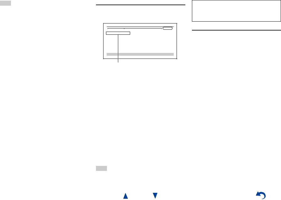
Note
•You can cancel Audyssey MultEQ® Room Correction and Speaker Setup at any point in this procedure simply by disconnecting the setup microphone.
•Do not connect or disconnect any speakers during Audyssey MultEQ Room Correction and Speaker Setup.
•If the AV receiver is muted, it will be unmuted automatically when Audyssey MultEQ Room Correction and Speaker Setup starts.
•Changes to the room after Audyssey MultEQ Room Correction and Speaker Setup requires you run Audyssey MultEQ Room Correction and Speaker Setup again, as room EQ characteristics may have changed.
Error Messages
While Audyssey MultEQ Room Correction and Speaker Setup is in progress, one of the error messages below may appear.
MultEQ: Auto Setup
AUDYSSEY
Ambient noise is too high.
Retry
Cancel
Error message
The options are:
`Retry:
Try again.
`Cancel:
Cancel Audyssey MultEQ Room Correction and Speaker Setup.
• Ambient noise is too high.
The background noise is too loud. Remove the source of the noise and try again.
• Speaker Matching Error!
The number of speakers detected was different from that of the first measurement. Check the speaker connection.
• Writing Error!
This message appears if saving fails. Try saving again. If this message appears after 2 or 3 attempts, contact your Onkyo dealer.
• Speaker Detect Error
This message appears if a speaker is not detected. “No” means that no speaker was detected.
Tip
•See “Speaker Configuration” for appropriate settings ( page 12).
En-26
Turning On & Basic Operations
The setup of the speaker can be done manually ( page 55).
The setup of the volume level of each speaker also can be done manually ( pages 56, 57).
Using a Powered Subwoofer
If you’re using a powered subwoofer and it outputs very low-frequency sound at a low volume level, it may not be detected by Audyssey MultEQ Room Correction and Speaker Setup.
If the “Subwoofer” appears on the “Review Speaker Configuration” screen as “No”, increase the subwoofer’s volume to the half-way point, set it to its highest crossover frequency, and then try running Audyssey MultEQ Room Correction and Speaker Setup again. Note that if the volume is set too high and the sound distorts, detection issues may occur, so use an appropriate volume level. If the subwoofer has a low-pass filter switch, set it to Off or Direct. Refer to your subwoofer’s instruction manual for details.
Performing Wireless LAN Setup
A wireless LAN (WLAN) is a local area network that relies on wireless communication.
To achieve a wireless network connection, you will need the following component:
■Access point
Also known as the base station, it links your AV receiver (wireless client) with a PC or network. Access points fall into two categories: the bridge type that only performs data relay in a local area network, or the router type that has a built-in router functionality.
To achieve a wireless network connection, it is necessary to perform the wireless LAN setup. The setup can be done either automatically or manually. You use your AV receiver as a wireless client (wireless terminal) and connect it to a PC or to the Internet.
Automatic wireless LAN setup
1 |
Press RECEIVER followed by HOME. |
2 |
Use e/ror q/wto select “Setup”, and then |
|
press ENTER. |
3 |
Use q/wto select “Hardware Setup”, and then |
|
press ENTER. |
4 |
Use q/wto select “Network”, and then press |
|
ENTER. |
|
|
|
|
Turning On & Basic Operations |
|
5 |
Use |
qw |
■PIN code method |
||
/ to select “Network Connection”, and |
1. Use q/wto select “PIN Code” and then press |
||||
|
e/rto select “Wireless”, and then press |
||||
|
ENTER ( page 67). |
ENTER. |
|||
|
The “Wireless Setup” menu is displayed on |
An 8-digit PIN code is displayed. The PIN |
|||
|
screen. |
code is displayed scrolling on the AV |
|||
|
|
|
|
receiver’s display. |
|
|
Tip |
|
|
||
|
|
|
2. Input the provided code in your Access Point. |
||
|
• The same setting is available even if “Wireless” is |
||||
|
For information on the registration process, |
||||
|
selected in “Network Connection” in initial setup |
||||
|
please refer to the instruction manual |
||||
|
( page 23). |
||||
6 Press q/wto select (North American models) |
provided with your Access Point device. |
||||
7 Press ENTER to confirm. |
|||||
|
“Push Button Configuration (Other |
||||
|
Routers)”*1/(excluding North American |
Connection to your Access Point starts and Wi-Fi |
|||
|
models) “Push Button Configuration (Select |
indicator flashes. After the connection to your |
|||
|
from Router)”, and press ENTER. |
Access Point is completed, Wi-Fi indicator lights |
|||
|
The method to make settings by “Push Button |
and the connection status is displayed on the |
|||
|
Configuration” is displayed, providing the |
screen. |
|||
|
following two options: |
This completes the wireless LAN setup. |
|||
|
|
|
|
You can review your setup with the “Status” |
|
Tip
option on the “Wireless Setup” menu.
*1 (North American models) To connect to Linksys
E/EA Router, select “Push Button Configuration (Linksys E/EA Router)” and make settings following the instructions on the screen.
■Push Button method
1.Use q/wto select “Push Button” and then press ENTER.
2.Press the WPS button on your Access Point device.
Note
•If Wi-Fi indicator doesn’t light, the connection to your Access Point is not done successfully. Configure this setting again ( page 80).
Tip
•How long the WPS button should be pressed differs depending on the type of Access Point device. Refer to the instruction manual provided with your Access Point device for operations.
En-27

Manual wireless LAN setup
1 |
Press RECEIVER followed by HOME. |
2 |
Use e/ror q/wto select “Setup”, and then |
|
press ENTER. |
3 |
Use q/wto select “Hardware Setup”, and then |
|
press ENTER. |
4 |
Use q/wto select “Network”, and then press |
|
ENTER. |
5 |
Use q/wto select “Network Connection”, and |
|
e/rto select “Wireless”, and then press |
|
ENTER ( page 67). |
The “Wireless Setup” menu is displayed on screen.
Tip
•The same setting is available even if “Wireless” is selected in “Network Connection” in initial setup ( page 23).
6 Use q/wto select “Search Wireless Network” and then press ENTER.
A list of available Access Points is displayed.
Tip
•If Access Point you wish to connect to is not displayed in the list of available Access Points, the setting also can be made by entering “SSID”, “Security”, and “Password” manually after selecting “Direct Input”.
|
|
|
Turning On & Basic Operations |
7 Use q/wto select the Access Point you wish to |
8 Select “OK” and press ENTER. |
||
connect to, and then press ENTER. |
|
Connection to your Access Point starts and Wi-Fi |
|
Depending on your encryption settings, the |
|
indicator flashes. After the connection to your |
|
security of your Access Point will provide one of |
|
Access Point is completed, Wi-Fi indicator lights |
|
the following patterns: |
|
and the connection status is displayed on the |
|
■WEP method |
|
screen. |
|
|
This completes the wireless LAN setup. |
||
1. Use q/wto select “Default Key ID” and then |
|
||
|
You can review your setup with the “Status” |
||
press ENTER. |
|
||
|
option on the “Wireless Setup” menu. |
||
2. Use q/wto choose an ID between 1 and 4, |
|
||
|
|
|
|
|
Note |
|
|
and then press ENTER. |
|
|
|
|
• If Wi-Fi indicator doesn’t light, the connection to your |
||
3. Use q/wto select “Password” and then press |
|
||
|
Access Point is not done successfully. Configure this |
||
ENTER. |
|
||
|
setting again ( page 80). |
||
4. Use the keyboard on screen to enter the |
|
||
|
|
|
|
password and confirm with “OK”. |
|
|
|
■WPA/WPA2 method
1.Use q/wto select “Password” and then press
ENTER.
2.Use the keyboard on screen to enter the password and confirm with “OK”.
■No encryption
If your Access Point device is not secured by encryption, there is no need to input any secret key.
Tip
•When you select the Access Point you wish to connect to from the list of available Access Points, “SSID” and “Security” are automatically displayed. These settings can be changed manually.
En-28
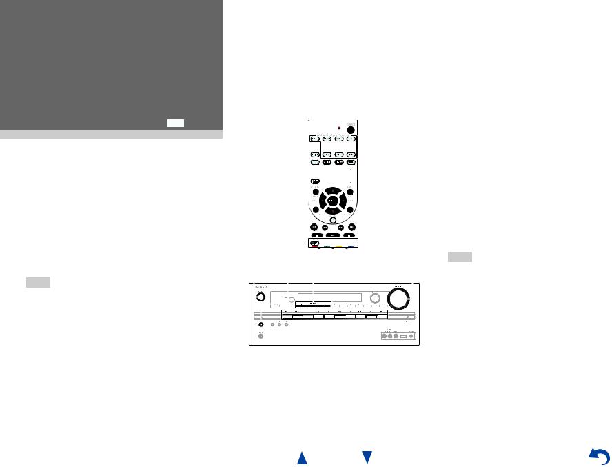
Playback
Playback
This section describes the basic operation such as playback, listening mode, and other useful functions. Reading this manual from the beginning to this section helps you to understand the basic connection/setup/operation.
Screen Saver
If there is no video signal on the current input source and no operation for a specific time (three minutes by default), a screen saver automatically comes on.
Tip
•The time until the screen saver activates itself can be changed in the “Screen Saver” setting
( page 64).
•The screen will return to its previous state if the AV receiver is operated.
See also:
•“Playing an Audio from Bluetooth-enabled Device” ( page 31)
•“Playing a USB Device” ( page 32)
•“Listening to TuneIn” ( page 32)
•“Registering Other Internet Radio” ( page 34)
•“Playing Music Files on a Server (DLNA)” ( page 34)
•“Playing Music Files on a Shared Folder” ( page 36)
•“Remote Playback” ( page 37)
•“Listening to AM/FM Radio” ( page 38)
•“Playing Audio and Video from Separate Sources” ( page 40)
•“Controlling Other Components” ( page 71)
•“Using the Onkyo Dock” ( page 75)
1 


 2
2 

 4
4


 3
3
1 |
|
2 |
3 |
|
|
4 |
||||||||||||||
|
|
|
|
|
|
|
|
|
|
|
|
|
|
|
|
|
|
|
|
|
|
|
|
|
|
|
|
|
|
|
|
|
|
|
|
|
|
|
|
|
|
|
|
|
|
|
|
|
|
|
|
|
|
|
|
|
|
|
|
|
|
|
|
|
|
|
|
|
|
|
|
|
|
|
|
|
|
|
|
|
|
|
|
|
|
|
|
|
|
|
|
|
|
|
|
|
|
|
|
|
|
|
|
|
|
|
|
|
|
|
|
|
|
|
|
|
|
|
|
|
|
|
|
|
|
|
|
|
|
|
|
|
|
|
|
|
|
|
|
|
|
|
|
|
|
|
|
|
|
|
|
|
|
|
|
|
|
|
|
|
|
|
|
|
|
|
|
|
|
|
|
|
|
|
|
|
|
|
|
|
|
|
|
|
|
|
|
|
(Actual location of buttons depends on the country.)
1 Turn on the AV receiver, the TV and the AV components.
*When you operate the AV receiver with the remote controller, press the RECEIVER button first.
En-29
Playback
2 Select the input on the AV receiver to play the AV components.
Press the input selector button to which the AV components to be played is connected.
Press the TV/CD button to play the audio of the TV. Switching the input on the TV is also required. Select the input to which the AV receiver is connected by using the TV remote controller.
*For the CEC compatible TV and the AV components connected with HDMI connections, switching the input is automatically performed. Switch the input manually for other AV components.
3 Select the desired listening mode.
You can enjoy various types of listening mode. The listening mode is switched by pressing Listening mode button on the AV receiver or the remote controller.
4 Adjust the volume.
You can enjoy the surround sound.
Tip
•When listening to an HDMI component through the AV receiver, set the HDMI component so that its video can be seen on the TV screen (on the TV, select the input of the HDMI component connected to the AV receiver). If the TV power is off or the TV is set to another input source, this may result in no sound from the AV receiver or the sound may be cut off.
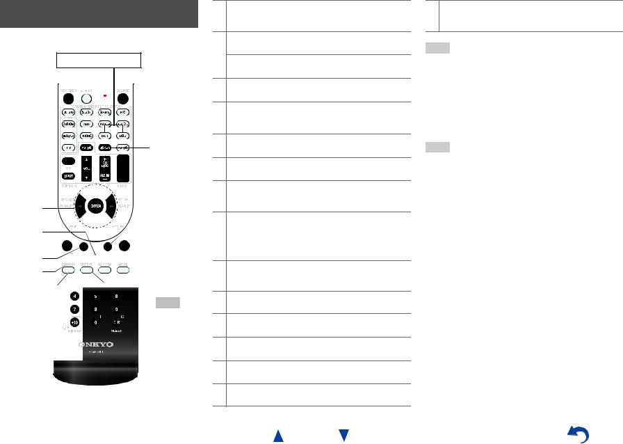
Controlling Contents of USB or Network Devices
( page 31)
Press USB or NET first.
h
a


 i
i
b


 j c
j c 
 k d
k d


 l
l
e

 m
m
f 


 n g
n g 

 o
o
aTOP MENU
This button displays the top menu for each media or service.
bq/wand ENTER
These buttons navigate through the menus.
e/r
This button cycles through pages.
c1
This button starts playback.
d7
This button selects the beginning of the current song. Pressing this button twice selects the previous song.
e5
This button fast-reverses the current song.
f3
This button pauses playback.
gSEARCH
You can toggle between the playback screen and the list screen during playback.
hDISPLAY
This button switches between song information during playback.
Press this button while the list screen is displayed to return to the playback screen.
iMENU
This button displays the menu of Internet radio services.
jRETURN
This button returns to the previous menu.
k4
This button fast-forwards the current song.
l6
This button selects the next song.
m2
This button stops playback.
nRANDOM
This button performs random playback.
En-30
Playback
oREPEAT
Press this button repeatedly to cycle through the repeat modes.
Tip
•See “Controlling Other Components” about the operation of other components ( page 71).
•The AV receiver supports Album art display, and displaying image file format of JPEG, PNG, and BMP is possible. The image file format cannot be displayed in either of the following cases:
–Total number of horizontal and vertical pixels is more than 2048 x 2048.
–Image data size (JPEG/PNG) is more than 4 MB.
Note
•The buttons you can use will differ depending on the devices and media used for playback.
•When you select the NET input selector on the AV receiver for the first time, “DISCLAIMER” screen is displayed on TV. Please read the contents thoroughly before using network service. Select “Agree” if you agree with the content. If you disagree, network service is not available on the AV receiver ( page 84).
Loading...