

Page 1

CS1 Series
CS1W-MC421/221
Motion Control Units
Specification Sheets
Page 2
Product Specifications
CS1 Special I/O Unit
CS1-series
Motion Control Units
CS1W-MC421/221
Multitasking G Language for Advanced, High-speed, and High-precision 2/4-axis
Motion Control
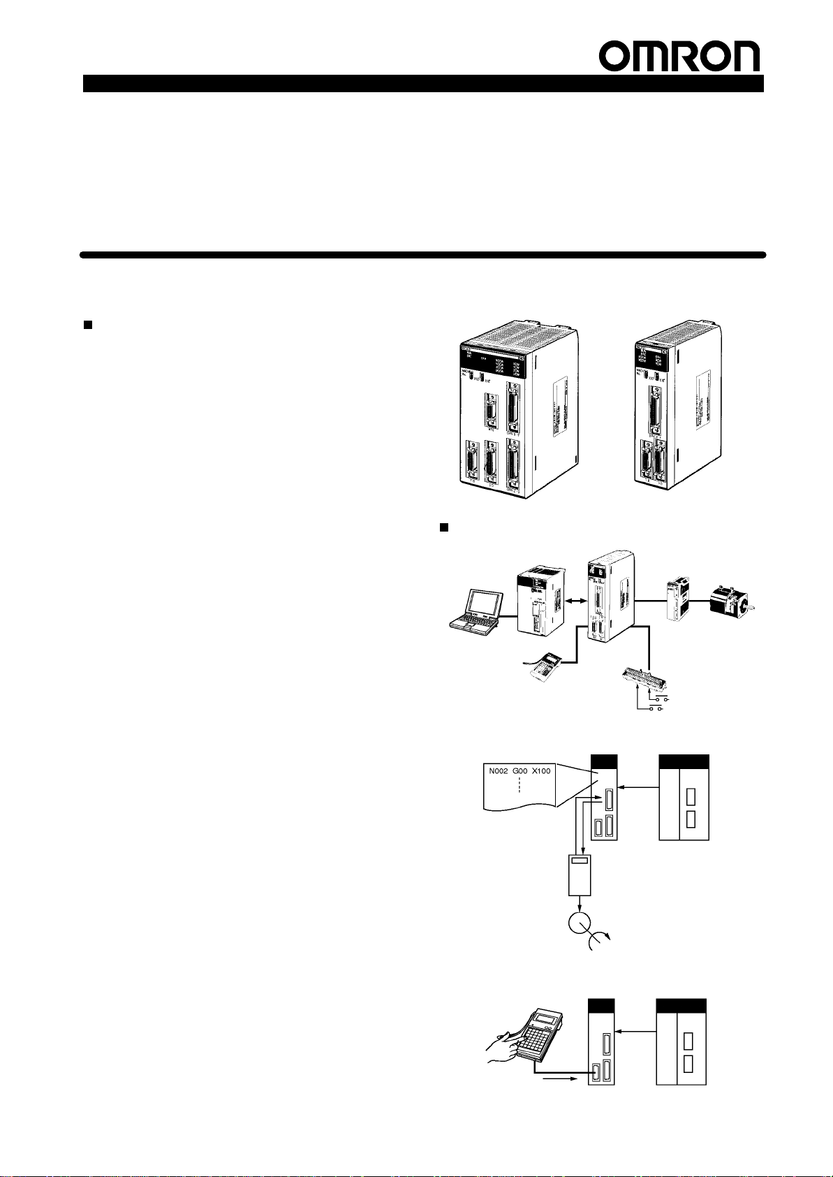
The CS1W-MC421 and CS1W-MC221 are
CS1-series Motion Control Units that control four
axes and two axes, respectively. With their built-in
G-language programming capability, they can be
used
for
advanced motion control operations, such
as traversing, and their multitasking capability
allows operations to be performed independently
for each axis. Two types of motion control are
possible: Point-to-point and continuous path.
1. Point-to-point Control: With point-to-point (PTP) control,
positioning is controlled independently for each axis. The
pathway varies according to the travel distances, the feed
rates,
and other set parameters.
2. Continuous Path Control: With continuous path (CP)
control,
not only the start position and target
controlled but also the path between those points. Linear
interpolation,
tion, and traversing are all possible.
The
MC Unit has been developed for use in simple position
applications using servomotors. Applicable machines are
ing
as
follows:
• Conveyor
loaders/unloaders,
• Assembling
(such as coil winding, polishing, hole punching), simple
robots,
Note: The
circular interpolation, or helical circular interpolation with
horizontal
it does not support coordinate conversions. The MC Unit
can,
circular interpolation,
Systems: X/Y tables, palletizers/depalletizers,
etc.
MC Unit is not designed to perform linear interpolation,
articulated robots or cylindrical robots,
however
etc.
Systems:
, perform PTP control with these robots.
Automated assembling machines
helical circular interpola
position can be
because
System Configuration
-
MC Support
-
Software
Automatic Mode
CS1W-MC421
CPU Unit
G language program
Teaching Box
MC Unit
(Example: CS1W-MC221)
CS1W-MC221
Analog input
servodriver
MC Terminal Block
Conversion Unit
CPU UnitMC Unit
Servomotor
“Programmable Controller” is abbreviated as “PC” in these
Manual Mode
Specification Sheets.
Teaching Box
Manual controls
MC Unit
Data bits
Operating
commands
Data bits
Manual
controls
CPU Unit
1
Page 3

Motion Control Units
MC
Unit functions
Automatic Mode
(Executes G-language programs
in the MC Unit.)
Manual Mode
(Executes manual commands
from the CPU Unit or T
Box.)
eaching
Product Specifications
Position control
Speed control
Origin search
Interrupt feeding
Traversing
Dwell timer
Arithmetic operations, etc.
Jogging
Deceleration stop
Present position preset
Origin search (manual)
Servo lock/Servo unlock
Error counter reset
Forced origin
Standard origin return
Absolute origin setting
Stop Mode
Pass Mode
In-position
Check OFF Mode
Common to Automatic
and Manual Modes
Features
Multitasking
The
MC Unit is
optimum
ple to create programs for multiaxis
den on the CPU Unit’
Simple and Fast T
Commands for 2-axis traverse operations enable simple and fast
traverse
Fast Pick-and-place Operations
After
OFF function allows the next positioning operation to be started
without waiting for the first positioning operation to be completed.
This
makes it possible to perform high-speed pick-and-place opera
tions.
Supports
The MC Unit is compatible with absolute encoders as a standard
feature,
encoders can be used as well.
tal
High-speed Response to Start Commands from CPU Unit
The
response time from when a start
CPU
ms
for two axes and 13 ms for four axes (MC421 only).
times
Note: T
500-kp/s Encoder Response Frequency
The maximum feedback encoder response frequency is 500 kp/s,
the MC Unit can be used with high-speed and high-precision ser
so
vomotors. This is double the response frequency of the earlier mod
els.
CPU Unit Interrupts
A
CPU
code (interrupt code) for the CPU Unit when positioning is com-
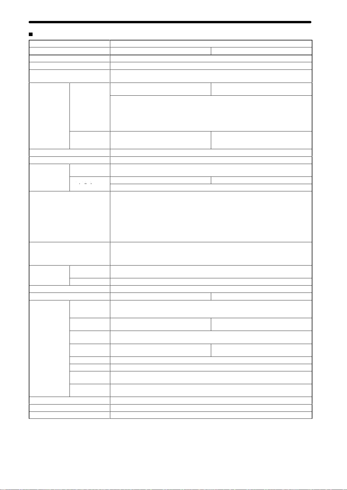
G Language
provided with a multitasking G language, which is the
language
operations.
a positioning command has been output,
eliminating the need to perform an origin search. Incremen
Unit until the command voltage is output from the MC Unit is
faster than the previous models.
wo-axis MC Unit
This function applies to the X axis when a 2-axis, 1-task
configuration
Four-axis MC Unit
This function applies to the X axis when a 4-axis, 1-task
configuration
Unit external interrupt task can be started by outputting a D
for motion control. The G language makes it sim
control, without placing a bur
s ladder diagram program.
raverse Operations
the in-position check
Absolute Encoders
command is received from the
This is 1.5
is used.
is used.
-
-
-
-
8
-
-
Teaching
Zones
Backlash correction
Override
Electronic gear
pleted
or when passing through a particular position.
ideal
for high-speed synchronization between the MC Unit and CPU
Unit.
Other
Functions
•
Unlimited Feeding
This function executes unlimited feeding for the specified axis.
Use of this function allows the user to control unlimitedly fed
axes, such as those for turntables or one-way conveyors. The
present value can be increased or decreased within the
specified
•
Synchronous Electronic Gear
Input pulses for a synchronous encoder can be accelerated or
decelerated for each axis at any timing. The acceleration or
deceleration
To
enabled
range.
rate is specified by a numerator/denominator
provide simple synchronous control,
or disabled for each axis at any timing.
this function can also be
This feature is
• Error Counter Reset
After a deceleration command has been completed, the error
counter
reset function forcibly sets the error counter to 0 to stop
the axis operation completely. This function is best suited for
machine
•
Multiturn Circular Interpolation
The multiturn circular interpolation function has been added to
the existing circular and helical circular interpolation functions.
This function can be used for applications such as winding
machine
•
Override (Real T
The speed can be changed during PTP, linear interpolation, or
circular interpolation operations in which the axis stops during
the
or
•
Pass Operations
The
pass operations. It is possible to specify whether to pass the
operation using the previous acceleration time or pass the
operation
is
rate
press control in molding and other processes.
operations.
ime Speed Change)
positioning operation. (This function is invalid in pass
in-position check OFF mode.)
acceleration and deceleration times can
using the deceleration time during
also possible to pass the operation at a constant
during single-axis pass operation.
be changed during
pass operations. It
acceleration
ratio.
mode
2
Page 4
Product Specifications
CS Se es
CS S ec a /O U
a og u se od e
Motion Control Units
• Servo
•
• Interrupt
•
Parameter Changes
The
servo gain, such as the
from a G language program. Therefore, if position loop
feed-forward gain is enabled during circular interpolation, the
level
of accuracy for circular interpolation can be improved.
Comprehensive Functions in Origin Search Mode
search pattern can be selected to reduce
The
time. It is possible to select either deceleration stop or error
counter-based stop when a limit input is received during origin
search. Origin searches are also possible in absolute encoder
systems.
This
move
It is possible to perform positioning
signals
Brake Signal Outputs
To
used as a general-purpose output) can be used during servo
lock
Feeding
function uses general-purpose inputs (interrupt signals) to
the specified axis by the specified distance for positioning.
are received during interrupt feeding.
make motor operation even easier
or unlock.
feed-forward gain, can be changed
The
the origin search
operations
, brake signal outputs (also
when no interrupt
• Stopover
A
stopover outputs M code or D (interrupt) code without stopping
operation
operation. The cycle time can be reduced by controlling
peripheral
after feeding the axis by the specified distance during
devices before the operation is completed.
• Error Logging
error log can store up to 20 error records, such as positioning
The
errors
or hardware errors in the MC Unit or operation fatal errors
in the CPU Unit, together with the date and time of each error.
The
error log can be read using the CX-Motion.
Windows-based MC Support Software: CX-Motion
•
Multiple MC Unit Management in Project Units
Multiple
MC Units can be registered as one project. This allows
simultaneous
• T
ree Display for Edit or Monitor Screens
Data
will be displayed in tree format on the left side of the window
management of multiple MC Units.
Models
Applicable PCs
CS1 Series
Unit classification
CS1 Special I/O Unit
Analog input servodriver
so that the user can easily understand the location of the data
currently
•
Servo Information T
Speed reference values, the present speed, and the error
counter can be traced with specified starting conditions and a
specified
Up
system.
• Automatic
When
can be stored in the MC Unit, programs or position data stored in
an
installed can be automatically downloaded to the MC Unit’s
internal
application
•
Single-port Multiaccess Function
A
can
the CX-Programmer, enabling multiple programming environments
•
User-defined Mnemonics
The user can enter G codes or mnemonics corresponding to
each G code when writing a program. The user can register or
change
analyze
•
File Conversion
The existing system parameters, position data, and programs
created
be
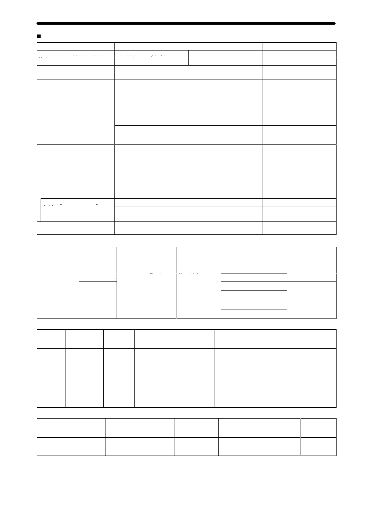
Data Creation Using T
In
addition to entering numbers
the
MC Support Software (CX-Motion), it
data by using the T
tion
moving
Operate with MPG
Positioning
MPG
Controlled driver
being set, edited, or monitored.
race Function
sampling period using the Windows-based
to 500 items can be traced, making it easy to adjust the servo
Loading Function
it is necessary to use more programs or position data than
external memory device at
memory
. This function allows the system to cope with
consisting of more than 100 programs.
Windows-based Support Software package called CX-Motion
be used on the same computer and through the same port as
on a single computer
these mnemonics as required, making it easy
MC programs.
using previous versions of the MC Support Software can
converted for use with the CX-Motion.
eaching Box
the machinery
and simple sync operations can be performed using
(manual pulse generator).
Number of controlled
4 CS1W-MC421
2 CS1W-MC221
eaching Box to teach positions while actually
.
axes
the computer where CX-Motion is
.
in the Position Data Edit Window of
is possible to create posi
CX-Motion.
an
to write or
an
Model
-
MC Unit Support Software (Sold Separately)
Name Computer Supported
CX-Motion IBM PC/A
compatible
T or
CS1W-MC421/221,
C200H-MC221,
CV500-MC421/221
Connecting Cables
Connection to CPU Unit Computer
Peripheral port
RS-232C port
IBM PC/A
IBM PC/A
T or compatible
T or compatible
MC Units
2.0 m, 6.0 m
2.0 m, 5.0 m
Specifications Model
Operating system:
Windows 95/98/NT V4.0
CPU: Pentium, 100 MHz
min.
Memory: 32 MB min.
Hard disk: 10 MB min.
CD-ROM drive: 1 min.
(for setup)
Functions: Creating and
editing system
parameters, creating and
editing position data,
creating MC programs
(G language), monitoring
MC Units, saving data in
flash memory
automatic loading, file
conversion, etc.
Cable length
, printing,
WS02-MCTC1-E
Cable model
CS1W-CNjjj
XW2Z-jjjS (-jj)
3
Page 5
Motion Control Units
ubeo
Specifications
Item Specifications
Model CS1W-MC221 CS1W-MC421
Applicable PC CS1 Series
T
ype of Unit
Backplanes on which MC Unit can
be mounted
Method for data
transfer with
CPU Unit Units in CIO
Controlled Driver
Built-in program language
Control
Automatic/Manual Mode (for each
task)
Encoder interface
Control unit
Maximum command value
Number of controlled axes
Positioning
operations
Speed reference
Acceleration/deceleration curve
Acceleration/deceleration time
W
ords allocated
to Special I/O
Area
W
ords allocated
to Special I/O
Units in DM Area
Control method
Number of
controlled axes
Minimum setting
unit
Units
PTP
(independent)
control
Linear
interpolation
Circular
interpolation
Helical circular
interpolation
T
raverse functionTraverse operation for two axes
Speed control
Unlimited Feed
Mode
Interrupt feeding
CS1 Special I/O Unit
CPU Backplane or CS1 Expansion I/O Backplane (See note 1.)
30 words/Unit (uses 3 unit numbers.) (See
note 2.)
CPU Unit to MC Unit:
Commands: G-language program execution/stop, origin search, manual operation, etc.
Data transfer: Position data, acceleration/ deceleration data, etc.
MC Unit to CPU Unit:
Status: Positioning completed, zones, busy flag, etc.
Monitor data: Present position, error codes, M codes, etc.
Not used. Not used.
Analog input servodriver (Example: OMRON OMNUC H, M, or U Series)
G language (Started by receiving a start command from the CPU Unit ladder diagram program.)
Speed reference voltage output-type semi-closed loop system, using incremental and absolute
encoder inputs.
2 max. 4 max.
Multitasking can be used to execute independent operating modes and programs for each axis.
Automatic Mode: Mode for executing MC program created in G language.
Manual Mode: Mode for executing manual commands from CPU Unit (PC interface area) or
T
eaching Box.
Note: The Automatic or Manual Mode is set according to the PC interface area of the CPU Unit.
There are a total of 1
return, JOG, and error reset.
The operation cycle is started in Automatic Mode through dedicated bits in the CPU Unit or from
the T
eaching Box.
Line receiver input; maximum response frequency: 500 kp/s (before multiplication)
Pulse ratio: Select 1, 2, or 4
Note: The applicable absolute encoder is the OMRON OMNUC U Series.
1, 0.1, 0.01, 0.001, 0.0001
mm, inch, degree, pulse (There is no unit conversion function.)
–39,999,999 to +39,999,999 (When the minimum setting unit is 1.)
2 axes max. 4 axes max.
Execution by independent programs, operating modes for each axis.
2 axes max 4 axes max.
Circular interpolation for a maximum of two axes on a plane.
---
Speed control for each axis
Axis feeding can be executed with no limit.
Feeding a fixed distance after an interrupt input, for each axis. (Positioning with no interrupt
input signals is also possible.)
1 pps to 2,000 kp/s (when ratio is 4)
T
rapezoidal or S-curve
Individual acceleration/deceleration settings possible: 0 to 100,000 ms (2-ms increments)
Product Specifications
50 words/Unit (uses 5 unit numbers.) (See
note 2.)
1 Automatic Mode commands, including origin search, reference origin
Circular interpolation for a maximum of two
axes on a plane + one axis for feed control
Note: 1. The
a CS1 Expansion Rack.
2. The
I/O Units that can be allocated words in the CPU Unit, the power supply capacity on the CPU or CS1 Expansion Rack, and the
current
4
MC Unit must be mounted to the CPU Rack to use D codes. D codes will not be sent to the CPU Unit
number of MC Units that can be mounted under one CPU Unit must be determined based on the maximum number of
consumption of the Units mounted to the
Rack. Refer to the CPU Unit’
s operation manual for details on calculation methods.
if the MC Unit is mounted to
Special
Page 6

Product Specifications
Conditions
sco o
as og a
Sa g og a
Item Specifications
External I/O
Feed operations
Axis control
T
ask program
management
Saving program
data
Peripheral
device
Encoder
MPG/sync
encoder
Servodriver
relationships
Individual axis
control
Others
Rapid feed rate
Interpolation
feed rate
Rapid feed
override
Interpolation
feed override
Jog feed
override
Zone settings
Backlash
correction
In-position zone Can be set from 0 to 10,000 pulses.
Position loop
gain
Feedforward
gain
Number of tasks
Number of
programs
Program
capacity
Position data
capacity
Number of
registers
Subroutine
nesting
MC Unit
External
peripheral
devices
Motion Control Units
T
eaching Box (1 only)
Line receiver inputs:
For two axes
(500 kp/s before multiplication)
Line driver output-type MPG/sync encoder: 1
500 kp/s max. (before multiplication)
The following signals are each provided for
two axes:
Inputs:
Outputs:
The following signals are each provided for
two axes:
Input:
General inputs: 4 pts. (interrupt inputs)
General outputs: 4 pts. (brake signal outputs)
Example: 36.86 m/min
Encoder resolution: 2,048 p/r
Motor speed: 4,500 r/m
Control unit: 0.001 mm/pulse
0.1% to 100.0% (Setting unit: 0.1%)
0.1% to 199.9% (Setting unit: 0.1%)
0.1% to 100.0% (Setting unit: 0.1%)
Up to 8 zones/axis can be set.
Can be set from 0 to 10,000 pulses.
1 to 250 (1/s)
0% to 100%
2 max. (program execution units) 4 max. (program execution units)
When 1 task is used:
When 2 tasks are used:
When 1 task is used:
When 2 tasks are used:
The maximum number of blocks in a single
program is 800.
2,000 positions max. (total for all axes)
32 (Mainly used for specifying position data numbers.)
5 levels max.
Backed up by flash memory
CX-Motion can be used to save data to a floppy disk or the hard disk at the personal computer
Driver alarm signals
Driver alarm reset signals
High-speed reference voltage outputs (±10 V)
Operation command outputs
SEN signals (for absolute encoder)
CCW limit inputs
CW limit inputs
Origin proximity inputs
Emergency stop inputs
n
iti
n
100
50
2,000 blocks
1,000 blocks/task
.
Line receiver inputs:
For four axes
(500 kp/s before multiplication)
The following signals are each provided for
four axes:
The following signals are each provided for
four axes:
When 1 task is used:
When 2 tasks are used:
When 3 task are used:
When 4 tasks are used:
When 1 task is used:
2,000 blocks
When 2 tasks are used:
1,000 blocks/task
When 3 task are used:
666 blocks/task
When 4 tasks are used:
500 blocks/task
The maximum number of blocks in a single
program is 800.
100
50
33
25
.
5
Page 7

Motion Control Units
o e su y o age
o age uc ua o o e a ce
Item Specifications
Program
download function
Self-diagnostic function
Error detection functions
Error log function
Model CS1W-MC221 CS1W-MC421
Settings
Indicators
Connections on front panel
Power supply voltage
V
Internal current consumption
W
Safety standards
External dimensions
Standard accessories
Cat. No.
and position data automatic
oltage fluctuation tolerance
eight (Connectors excluded)
When the operation number (program or position data) is specified by an IOWR instruction from
the CPU Unit, CX-Motion recognizes it and downloads the program or position data to the MC
Unit.
Memory corruption is detected.
Error counter warning, error counter over
communications errors (T
error
, phase-Z error
driver reverse wiring detection, CPU Unit error detection
Stores up to 20 error log records.
Front panel: Rotary switches for unit number
setting (0 to 93)
Rear panel: None
7 LED indicators: Running, MC Unit error
CPU Unit error
each axis (CCW/CW)
Servodriver connector
T
eaching Box connector (one each)
5 VDC (from Backplane)
24 VDC (from external power supply)
4.75-5.25 VDC (from Backplane)
21.6-26.4 VDC (from external power supply)
600 mA or less for 5 VDC (with T
connected: 800 mA or less)
450 g max. 540 g max.
Conforms to UL (Class 2), CSA (class 2), and EC specifications.
130.0 × 35 × 100.5 mm (H × W
Single-slot size
10136-3000VE snap-on connector for
Servodrivers and 10336-52F0-008 Connector
Cover (manufactured by Sumitomo 3M): 1 set
10126-3000VE snap-on connector for I/Os
and 10326-52F0-008 Connector Cover
(manufactured by Sumitomo 3M): 1 set
Antistatic screws: 4
W359
, motor rotation direction for
eaching Box), flash memory error
, overtravel, emergency stop, unit number error
, I/O connector
× D)
, absolute encoder error detection, CPU errors,
Front panel: Rotary switches for unit number
setting (0 to 91)
Rear panel: None
,
1
1 LED indicators: Running, MC Unit error
CPU Unit error
each axis (CCW/CW)
,
eaching Box
Servodriver connectors (two), I/O connector,
T
eaching Box connector
700 mA or less for 5 VDC (with T
connected: 1,000 mA or less)
130.0 × 70.0 × 100.5 mm (H × W
Double-slot size
10136-3000VE snap-on connector for
Servodrivers and 10336-52F0-008 Connector
Cover (manufactured by Sumitomo 3M): 2
sets
10126-3000VE snap-on connector for I/Os
and 10326-52F0-008 Connector Cover
(manufactured by Sumitomo 3M): 1 set
101
and 10314-52F0-008 Connector Cover
(manufactured by Sumitomo 3M): 1 set
Antistatic screws: 8
Product Specifications
, EEPROM error
, driver alarm detection,
, motor rotation direction for
14-3000VE snap-on connector for MPG
, software limit over
, MPG connector
,
eaching Box
× D)
6
Page 8
Product Specifications
C
e a oc Co e so
o eas e g o /O
(
(
eac g o Co ec g
CUU
eea
C/
9
e e a bus o
tibl
Options (Sold Separately)
Name Specifications Model
MC Terminal Block Conversion
Unit
MC T
erminal Block Conversion
Unit Cable
Snap-on connector for
Servodriver connector on Unit
front panel (1 or 2 sets provided
as standard on the Unit)
Snap-on connector for I/O
connector on Unit front panel (1
set provided as standard on the
Unit)
Snap-on connector for MPG
connector on Unit front panel (1
set provided as standard on the
CS1W
-MC421 Unit only)
T
eaching Box
T
eaching Box Connecting
Cable
ROM Cassette
For easier wiring of I/O
connectors
For connecting the I/O connectors on the front panel of the Unit
Soldered connector
Connector cover 10336-52F0-008
Soldered connector
Connector cover 10326-52F0-008
Soldered connector
Connector cover 10314-52F0-008
Jogging, origin search, present value monitoring, and other
operations by means of manual commands
T
eaching (taking present values into position data)
Cable length: 2 m
Cable length: 4 m
Cable length: 6 m
Required when the CVM1-PRS21-V1 Programming Console is
used as a T
eaching Box.
Motion Control Units
2-axis XW2B-20J6-6
4-axis XW2B-40J6-7
XW2Z-100J-F1
10136-3000VE (manufactured
by Sumitomo 3M)
(manufactured by Sumitomo
3M)
10126-3000VE (manufactured
by Sumitomo 3M)
(manufactured by Sumitomo
3M)
101
14-3000VE (manufactured
by Sumitomo 3M)
(manufactured by Sumitomo
3M)
CVM1-PRO01-E
CV500-CN224
CV500-CN424
CV500-CN624
CVM1-MP702
CX-Motion Connecting Cables
Unit Port on Unit Computer Port on
CPU Unit Peripheral
RS-232C
p
(9-pin D-sub
female)
Serial
Communications
Board/Unit
Connecting RS-232C Cable to Peripheral Port
Unit Port on Unit Computer Port on
CPU Unit
Connecting CQM1-CIF01/02 Cable to Peripheral Port
Unit Port on Unit Computer Port on
CPU Unit
RS-232C
p
(9-pin D-sub
female)
Peripheral port
Peripheral port
IBM PC/.A
or
compa
IBM PC/.A
or
compatible
IBM PC/.A
or
compatible
p
T
T
computer
T 9-pin
D-sub
e
male
computer
9-pin D-sub
male
computer
9-pin D-sub
male
Serial
communications
mode (network)
Peripheral bus or
Host Link
Host Link
Serial
communications
mode (network)
Peripheral bus or
Host Link
Host Link CS1W-CN1
Serial
communications
mode (network)
Host Link CS1W-CN1
Model numbers
CS1W-CN226
CS1W-CN626
XW2Z-200S-CV
XW2Z-500S-CV
XW2Z-200S-CV
XW2Z-500S-CV
Model numbers
CS1W-CN1
XW2Z-200S-CV
or
XW2Z-500S-CV
XW2Z-200S-V
or
XW2Z-500S-V
Model numbers
CQM1-CIF02
18 +
18 +
14 +
Length Remarks
2.0 m
6.0 m
2.0 m
5.0 m
2.0 m
5.0 m
Length Remarks
0.1 m +
(2 or 5 m)
0.5 m + 3.3 m
---
ESD (static electricity)-resistant connectors used.
ESD (static
electricity)- resistant
connectors used for
XW2Z-j00S-CV.
---
Length Remarks
---
7
Page 9

Motion Control Units
aua
Product Specifications
Connecting an IBM PC/A
Unit Port on Unit Computer Port on
CPU Unit RS-232C
Serial
Communications
Board/Unit
T or Compatible with RS-232C Cable
IBM PC/.AT9-pin D-sub
p
(9-pin D-sub
female)
RS-232C
p
(9-pin D-sub
female)
or
compatible
Applicable CPU Units
PC CPU
CS1-series CS1H-CPUjj
Unit model
number
CS1G-CPUjj
T
CS1W
numbers; unit numbers 0 to 93)
CS1W
numbers; unit numbers 0 to 91)
The current consumption must be within the allowable range for the
Power Supply Unit.
Overview of Operations
Item Contents
Operating
Manual
modes
Jogging
Handle feed
Deceleration stop Decelerates to a stop according to command.
Manual origin search
Manual origin return
Forced origin Forcibly sets the present position to 0 to establish it as the origin. (In an absolute
Absolute origin setting Sets the origin for an absolute encoder
Servo-lock
Servo-unlock
Electronic gear function
computer
male
otal number of MCUs that can be mounted on CPU Racks and
-MC221: 32 Units (each Unit requires 30 words equivalent to 3 unit
-MC421: 19 Units (each Unit requires 50 words equivalent to 5 unit
The following two modes are available.
Manual Mode: Operation according to CPU Unit memory area or commands from
Teaching Box.
Automatic Mode: Operation according to commands in G-language program.
Moves axes continuously by manual operation.
Moves axes by MPG.
Searches for mechanical origin. (Origin search is possible in either an incremental or
absolute encoder system.)
Moves to origin in reference coordinate system.
encoder system, only the present position of the MC Unit will be set to 0.)
Creates a position loop and turns ON the operation command output to the
servodriver
used, the absolute position is read before the servo-lock is applied.
Releases the position loop and applies the brake, and simultaneously turns OFF the
operation command output to the servodriver
Automatic Mode.
A fixed ratio (numerator and denominator) can be applied to input pulses, and output
to the servomotor driver
Expansion I/O Racks
, while simultaneously releasing the brake. When an absolute encoder is
Serial
communications
mode (network)
Host Link
Host Link
.
Model
numbers
XW2Z-200S-V
XW2Z-500S-V
XW2Z-200S-V
XW2Z-500S-V
.
. Servo-unlock can be executed even in
Length Remarks
2 m
5 m
2 m
5 m
Unit location
None
---
restrictions
8
Page 10

Product Specifications
Item Contents
Automatic
Automatic
Automatic and
Manual Mode
Positioning
interpolation
Positioning with circular
interpolation
Positioning with helical
circular interpolation
T
raverse function
Speed control
Interrupt feeding
Switching to Pass Mode
Switching to In-position
Check OFF Mode
Stop-over function
Dwell timer
W
orkpiece origin return
Automatic origin return
Cycle start
Single block
Pause T
Forced block end Forcibly ends execution of a block.
Error reset Clears error status.
M code reset
Teaching
Auxiliary
Backlash correction
Error counter reset
Override
Zones
Unlimited Feed Mode,
unlimited present position
display
Origin search function
Trapezoid/S-curve
acceleration and
deceleration
Driver alarm reset
Data transfer
Servo data trace function
with linear
Optional inputs
M code
D code
(interrupt code)
Motion Control Units
Executes linear interpolation at the specified interpolation feed rate for up to either
two or four axes simultaneously
Executes clockwise or counterclockwise 2-axis circular interpolation at the specified
interpolation feed rate.
Executes clockwise or counterclockwise 2-axis circular interpolation and 1-axis linear
interpolation (i.e., helical interpolation) at the specified interpolation feed rate.
(A
vailable for CS1W
Executes winding (traverse operation).
Moves a maximum of either two or four axes at a controlled speed.
Moves a specified axis for a fixed amount when a general input is turned ON. With
interrupt feeding, positioning without an interrupt signal can be executed.
Changes to Pass Mode, in which operations are executed one by one with no
deceleration stop. In Pass Mode, the interpolation acceleration or deceleration time of
the previous operation can be specified for the next operation (Pass Mode time
selection). A pass operation for only one axis can be executed at a fixed acceleration
(with a fixed acceleration mode setting).
Starts the next positioning operation without waiting for the current one to be
completed.
Outputs an M code or a D code while axes are being moved by a fixed amount
(determined by present position), without stopping the operation. G codes are also
possible for all operations.
Pauses positioning for a specified time.
Automatically returns to workpiece origin.
Automatically returns to reference coordinate system origin.
Executes a specified program from the first block, or resumes execution of a stopped
program.
Executes the program one block at a time.
emporarily halts program execution.
Resets the M code (for interlock).
Creates position data for each task.
20 points: Specify input information to be referenced by special G code.
Of the 20 input points, 4 can be specified as general-purpose inputs for the MC Unit.
0 to 999
0 to 499: M code for taking interlock
500 to 999: M code not taking interlock
0 to 255
Starts a CPU Unit external interrupt task when positioning is completed or when
passing through a particular position.
The amount of correction for backlash in the mechanical system can be registered in
advance.
Forcibly resets the error counter to 0, and stops axis operation. (Enabled when no
speed reference is provided to the servodriver
Changes the operating speed by applying a specified percentage to the speed
specified in the system parameters or G-language program.
A zone flag turns ON when the present position enters a preset range.
Moves the axis with no limit. In this mode, a range for refreshing the present position
can be specified.
The search pattern can be selected to shorten the origin search time. Either a
deceleration stop or accumulated pulse stop can be selected for when a limit input is
received during the origin search.
Either trapezoid or S-curve acceleration and deceleration can be specified for starting
and stopping each axis.
Resets the servodriver alarm.
Data is transferred between the CPU Unit and the MC Unit by means of the CPU
Unit’
s IORD and IOWR instructions. There are two modes for transferring data: One
for transferring large amounts of data, and another for rapidly transferring small
amounts of data.
Up to 500 data items, including speed reference values, present speed, and error
counter data, can be traced for each axis. This data can be referenced by CX-Motion.
-MC421 only
.
.)
.)
9
Page 11

Motion Control Units
Comparison with Earlier MC Unit Model
The
following table shows the points of dif
Item CS1W-MC221/MC421 C200H-MC221
Number of control axes
Binary indications
Encoder response frequency
Encoder pulse ratio
Program capacity
Acceleration/deceleration time
Speed reference range
Start time
Optional inputs
General outputs, brake signal outputs
MPG signals
ference between the CS1W
2 or 4 axes
All binary (present position, program
number
, block number
error code)
500 kp/s (before multiplication) 250 kp/s (before multiplication)
1, 2, or 4 times
2,000 blocks
0 to 100.000 s
1 pps to 2,000 kp/s 1 pps to 1,000 kp/s
2-axis Units: 8 ms max.
4-axis Units: 12 ms max.
Note: Two-axis MC Unit:
This function applies to the X axis when a 2-axis, 1-task configuration is used.
Four-axis MC Unit:
This function applies to the X axis when a 4-axis, 1-task configuration is used.
Optional No. 0 to 15: Inputs from CPU Unit
Optional No. 16 to 19: General inputs 1 to 4
Four output signals are provided, and can
be selected.
500 kp/s max. (before pulse ratio of 1, 2, or4)Y axis instead of MPG
Product Specifications
-MC221/MC421 and C200H-MC221 MC Units.
2 axes only
BCD
, M code, override,
4 times only
800 blocks
0 to 9.999 s
2-axis Units: 12 ms max.
Optional No. 0 to 4: Inputs from CPU Unit
Optional No. 5 and 6: General inputs 1 and
2
No output signals are provided.
Circular interpolation (G02, G03)
Helical circular interpolation
T
raverse command (G32)
Unlimited Feed Mode
Present position display for unlimited
feeding
Interrupt feeding (G31) Positioning is possible even without
Override The feed rate can be changed during
Multiturn circular interpolation can be set.
With 4-axis Units, 2-axis circular
interpolation on a plane + 1-axis feed
control is possible.
A 2-axis traverse operation is available,
with a traverse time of 4 ms max.
Unlimited feeding can be either specified or
not specified for an axis. (The software limit
is ignored.)
When unlimited feeding is specified for an
axis, the software limit is ignored. The
present position refresh range can be set.
any interrupt signal.
G00, G01, G02, G03, G26, G27, G30,
Within one turn only
Not supported.
Not supported.
Cannot be specified.
Not supported.
Speed control remains in effect when
there is no interrupt signal.
The feed rate cannot be changed
during operation.
G31, and G32 operations (except for
pass operations).
Backlash setting range 0 to 10,000 pulses 0 to 999 pulses
In-position setting range 0 to 10,000 pulses 0 to 999 pulses
Zone setting Conditions for using zones:
Use only when origin is determined, or
Use regardless of whether or not the
origin is established.
regardless of whether or not origin is
determined.
The initial setting is for zones to be
used only when the origin is
established.
Origin search Can be executed even when an
absolute encoder is used.
Parameter can be set to shorten origin
search time.
Either deceleration stop or
Cannot be executed when an absolute
encoder is used.
Not possible to select deceleration
stop or accumulated pulse stop for
when CW or CCW limit is detected.
accumulated pulse stop can be
selected for when CW or CCW limit is
detected.
Forced origin Present position can be forcibly set to
0, and established as the origin. (In an
The present position is set to 0 by the
present position preset function.
absolute encoder system, only the MC
Unit’s present position is set to 0.)
.
10
Page 12

Product Specifications
ggg
Item C200H-MC221CS1W-MC221/MC421
Absolute encoder origin setting The absolute encoder origin can be
Electronic gear function The numerator and denominator can
IN-POSITION CHECK OFF command
(G13)
Error counter reset The error counter can be reset for
D code (interrupt code) Can be used for notifying of the CPU
Stopover function (Code output during
axis movement)
Acceleration/deceleration time setting
for pass operations
Fixed acceleration mode for pass
operations
Servo system parameter changes
(G code: G69)
Servo-lock There is a brake signal timing
Servo-unlock There is a brake signal timing
Error log Up to 20 items can be saved. Not supported.
Absolute value initial setting
Absolute value software reset
MPG Operating Flag Busy signal is used instead. Not supported.
Servo data trace function Traces servo data. Can be used with
Data transfer method All data is transferred using IORD or
Present position preset Executed by IOWR. Executed by special interrupt bit.
Setting teaching address Executed by IOWR. Executed by special interrupt bit.
Saving to flash memory Executed by IOWR. Executed by special interrupt bit.
Emergency stop method Stopped by accumulated pulse
Automatic loading G-language programs and position
set even while servo-lock is in effect.
be set.
After a positioning command output
has been completed, this command
lets the next operation start without
waiting for positioning to be
completed.
each axis.
Unit of interrupts.
An M code or D code can be output
after a fixed amount of axis movement
during operation.
Either the acceleration or deceleration
time of the previous operation can be
selected for pass operations.
A fixed acceleration mode is added for
when pass operations are executed
for one axis only.
Servo system parameters can be
changed by a G code.
adjustment function.
adjustment function. Servo-unlock can
be used at any time.
Integrated with absolute origin setting.
CX-Motion.
IOWR.
method or by operation command
output turning OFF after a 0 V output.
data are downloaded from a personal
computer by means of commands
from the CPU Unit, used in
combination with CX-Motion.
Origin is set by either the
absolute-value initial setting or the
absolute-value software reset
function. (It cannot be set while
servo-lock is in effect.)
Integers only
Not supported.
Not supported.
Not supported.
Not supported.
Pass operations are executed with the
acceleration time.
Fixed acceleration time mode only
Not supported.
There is no brake signal timing
adjustment function.
There is no brake signal timing
adjustment function. Servo-unlock
cannot be used while other manual
commands are being executed.
Not supported.
Not supported.
Not supported.
Data is transferred by means of either
I/O transfers or IORD/IOWR.
Stop by turning OFF operation
command output.
Not supported.
Motion Control Units
11
Page 13

Motion Control Units
Product Specifications
Performance
The
following table shows the typical values of each performance item. These values, however, vary according to the task configuration, axis
configuration,
Power ON startup time
Cyclic service time CS1W-MC221:
IOWR execution time
IORD execution time
Data write time
Data read time
Operation startup time
Analog voltage output time lag per axis for
interpolation
Analog voltage output time lag per axis for
independent operation
Interrupt notification time
G language interpretation time
Minimum operation time
Minimum traverse reversal time
External input response time
Zone Flag notification time
and so on. For details, refer to the
Item T
Motion Control Units Operation Manual
ypical value
A
verage: 600 ms
CS1W-MC421:
0.7 ms/instruction
0.8 ms/instruction
475 ms/1,000 words
470 ms/1,000 words
CS1W-MC221:
CS1W-MC421:
CS1W-MC221:
CS1W-MC421:
CS1W-MC221: 4.3 ms/axis
CS1W-MC421: 4.3 ms/axis
2.25 ms
CS1W-MC221:
CS1W-MC421:
CS1W-MC221:
CS1W-MC421:
2 ms
General purpose input:
Emergency stop input:
CW/CCW limit input:
Origin proximity input:
CS1W-MC221:
CS1W-MC421:
0.8 ms/Unit
0.85 ms/Unit
8 ms
12 ms
150
µs
210
µs
2.0 ms
4.2 ms
8.5 ms
9.5 ms
1 ms max.
4.5 ms max.
4.5 ms max.
4.5 ms
14.08 ms
34.08 ms
(W359-E1-1).
Description
T
ime from turning ON the power until
manual operation commands are accepted.
T
ime by which the CPU Unit cycle time will
be extended per MC Unit.
T
ime by which the cycle time will be
extended when IOWR is executed.
T
ime by which the cycle time will be
extended when IORD is executed.
T
ime from when IOWR is executed until
data transfer is completed.
T
ime from when IORD is executed until
data transfer is completed.
MC221: T
1-task, 2-axis configuration.
MC421: T
1-task, 4-axis configuration.
T
ime delay when interpolation is performed
for 1 task.
T
ime delay when one axis each is started
for all tasks simultaneously
When C200H
not mounted.
Interpretation time for G language when
axis movement is not performed.
When the time for linear interpolation is
equal to or less than the values give, Stop
Mode operation will be used even in Pass
Mode or In-Position Check OFF Mode.
Reversing operation is possible every 2 ms
for traverse operation.
Response time to external input signals.
The time required for one Zone Flag to
respond.
ime for X axis operation with a
ime for X axis operation with a
.
j-series Special I/O Unit is
G Language
Example
N000 P001 XY
Program number and axis declaration
N001 G91
Incremental Specification
N002 G00 X100 Y50 M001
Positioning: Moves the X axis by 100 and the Y axis by 50
from the present position, and outputs M code 001 after
positioning has been completed.
Block
number (N000 to N999): Equivalent to a program line number
G code: 2-digit number following “G” represents a command.
.
12
Page 14

Product Specifications
Code
ae
Code
ae
Motion Control Units
Code Name
G00 Positioning
G01
G02
G03
G04
G10
G11
G13 IN-POSITION CHECK OFF MODE
G17
G18 CIRCULAR PLANE SPECIFICATION (X-Z)
G19 CIRCULAR PLANE SPECIFICATION (Y-Z)
G20 CIRCULAR PLANE SPECIFICATION (X-U)
G21 CIRCULAR PLANE SPECIFICATION (Y-U)
G22 CIRCULAR PLANE SPECIFICATION (Z-U)
G26
G27 W
G28
G29 Origin UNDEFINED
G30 SPEED CONTROL
G31 INTERRUPT FEEDING
G32 traverse
G50
G51
G53
G54
G60
G63 Substitution
G69
G70
G71
G72
G73
G74
G75
G76
G79
G90
G91
Linear Interpolation
Circular Interpolation (Clockwise)
Circular Interpolation (Counterclockwise)
Dwell T
imer W
Pass Mode
Stop Mode
Circular Plane Specification (X-Y)
Reference Origin Return
orkpiece Origin Return
Origin Search
Select Reference Coordinate System Specifies the reference coordinate system.
Select W
Change W
Change Reference Coordinate System PV
Arithmetic Operations
Change Parameter
Unconditional Jump
Conditional Jump
Subroutine Jump
Subroutine End
Optional End
Optional Skip Skips the block after this command when the specified optional input is ON.
Optional Program Stop
Program End
Absolute Specification Positions with absolute coordinates when performing axis operations.
Incremental Specification
orkpiece Coordinate System
orkpiece Origin Of
fset
Function
4-axis MCU
CS1W-MC221 CS1W-MC421
Positions up to 2 or 4 axes simultaneously with PTP control at the maximum
feed rate.
Performs linear interpolation on 1, 2, 3, or 4 axes (1 or 2 axes for MC221).
The specified axes move simultaneously
The feed rate can be specified.
Performs 2-axis circular interpolation in the clockwise direction at the
specified interpolation feed rate.
Performs 2-axis circular interpolation in the counterclockwise direction at the
specified interpolation feed rate.
aits for the specified length of time.
Performs operations one-by-one in sequence without waiting for
deceleration to stop.
Performs the next operation after completing positioning.
Starts the next operation without waiting for positioning to be completed.
Sets the X-Y plane as the plane for circular interpolation.
Sets the X-Z plane as the plane for circular interpolation.
Sets the Y
Sets the X-U plane as the plane for circular interpolation.
Sets the Y
Sets the Z-U plane as the plane for circular interpolation.
Moves to the reference origin.
Moves to the workpiece origin.
Performs an origin search on the specified axis.
Sets the origin to an undefined state.
Feeds up to 2 axes simultaneously at the controlled feed rate.
Performs an interrupt feeding operation.
Executes traverse operation.
Specifies the workpiece coordinate system.
Changes the origin of the workpiece coordinate system.
Changes the present value in the reference coordinate system.
Performs arithmetic operations on numerical values, position data, and
registers.
Substitutes numerical values, position data, or registers into other position
data or registers.
Changes the specified parameter
Unconditionally jumps to the specified block.
Jumps to the specified block when the condition is met.
Calls the specified subroutine.
Ends the subroutine.
Ends the block currently being executed when the specified optional input is
ON.
Pauses the program when the specified optional input is ON.
Ends the main program.
Positions with relative coordinates when performing axis operations.
-Z plane as the plane for circular interpolation.
-U plane as the plane for circular interpolation.
.
.
2-axis MCU
Auxiliary Codes
Code Name
M
D D code
4-axis MCU
CS1W-MC221 CS1W-MC421
M code Outputs an M code.
Starts an external interrupt task for the CPU Unit.
Function
2-axis MCU
13
Page 15

Motion Control Units
System Configuration
Control System
Semi-closed
Feedback pulses and
present value information
(for absolute encoders)
Loop System
Product Specifications
MC Unit
Analog output
Servodriver
Tachogenerator
Rotary encoder
Connected Configuration
MPG or
synchronous
encoder
Teaching Box
XW2Z-100J-F1 MC Unit Terminal
Block Connecting Cable or
user-prepared cable
CCW limit input
CW limit input
Origin proximity input
Emergency stop input
for 4 or 2 axes
General-purpose inputs (4)
General-purpose outputs (4)
Servomotor
MC Unit
(Example: CS1W-MC421)
MPG connector
DRV X, Y
connectors
DRV Z, U connectors
I/O connector
MC Unit Terminal Block
CS1W-MC421: XW2B-40J6-7
CS1W-MC221: XW2B-20J6-6
CPU Unit
Power Supply Unit
Servodriver Connecting
Cable (for U/H/M-series) or
user-prepared cable
For connection to peripheral port on CPU
Unit: CS1W-CNjjj
For connection to RS-232C port on CPU
Unit: XW2Z-j00S(-CV)
Servodriver
Servomotor
CS1W-MC421:
4 axes
CS1W-MC221:
Servodriver
2 axes
14
Servomotor
Page 16

Product Specifications
Exchanging Data
CS1
Motion Control Units
CS1W-MC221
CIO Area Words
2000 to 2029
2010 to 2039
2020 to 2049
2030 to 2059
n to n+29
2900 to 2929
2910 to 2939
2920 to 2949
2930 to 2959
Reserved
Reserved
Data Memory Area
(Allocated areas are not used)
Data transfer words
Data
Unit #0
Unit #1
Unit #2
Unit #3
Unit #90
Unit #91
Unit #92
Unit #93
Unit #94
Unit #95
Transferred to each Unit during I/O refresh
IOWR/IORD instructions
I/O Refresh Data Area
OUT refresh
IN refresh
Reserved
n: 2000 + 10 × unit number
Address
Data saved.
A total of 30 words used.
Internal memory
Position data
System parameters
Monitor information
Special information
Flash memory
G-language program
S
S S S S
At startup or
when restarted.
S
CS1
CIO Area Words
2000 to 2049
2010 to 2059
2020 to 2069
2030 to 2079
n to n+49
2900 to 2949
2910 to 2959
Reserved
Reserved
Reserved
Reserved
Data Memory Area
(Allocated areas are not used)
Data transfer words
Data
Unit #0
Unit #1
Unit #2
Unit #3
Unit #90
Unit #91
Unit #92
Unit #93
Unit #94
Unit #95
Transferred to each Unit during I/O refresh
IOWR/IORD instructions
CS1W-MC421
I/O Refresh Data Area
A total of 50 words used.
n: 2000 + 10 × unit number
Internal memory
Address
Position data
System parameters
Monitor information
Special information
Data saved.
Flash memory
G-language program
OUT refresh
IN refresh
Reserved
S
S S S S
When powered
up
or restarted.
S
15
Page 17

Motion Control Units
U
Gee
C
ed
()
Component Names
CS1W-MC221 CS1W-MC421
Product Specifications
LED indicators
Unit number setting switch
MPG connector
DRV X-Y connector
10126-3000VE Connector
(Sumitomo 3M)
10326-52F0-008 Connector cover
(Sumitomo 3M)
(This unit is provided with 2 sets.)
Teaching Box
connector
I/O connector
Teaching Box
connector
Indicators
Indicator Color Status Meaning
RUN Green
ERC Red
ERH
XCCW
Red ON
Yellow
YCCW
ZCCW (See note.)
UCCW (See note.)
XCW
Yellow
YCW
ZCW (See note.)
UCW (See note.)
ON The
OFF
The MC Unit is not recognized by the PC or is
malfunctioning.
ON
OFF
An error occurred in the MC Unit.
The MC Unit is operating normally
An error occurred in the CPU Unit.
OFF
ON
The CPU Unit is operating normally
The motor for the applicable axis is turning in the CCW
direction. (The X to U axes correspond to XCCW to
UCCW.)
OFF
The applicable axis is stopped or is turning in the CW
direction.
ON
The motor for the applicable axis is turning in the CW
direction. (The X to U axes correspond to XCW to UCW
OFF
The applicable axis is stopped or is turning in the CCW
direction.
MC Unit is operating normally
LED indicators
Unit number setting switch
DRV X-Y connector
10126-3000VE Connector
(Sumitomo 3M)
10326-52F0-008 Connector cover
(Sumitomo 3M)
(This unit is provided with 2 sets.)
I/O connector
DRV Z-U connector
10126-3000VE Connector
(Sumitomo 3M)
10326-52F0-008 Connector cover
(Sumitomo 3M)
(This unit is provided with 2 sets.)
SU
.
.
.
.)
Note:
The CS1W
-MC221 does not have the ZCCW
, UCCW, ZCW
, and UCW indicators.
16
Page 18

Product Specifications
I/O Connector Wiring
I/O Connector
Snap-on
Connector: 10126-3000VE (provided with the Unit, manufactured by Sumitomo 3M)
Case: 10326-52F0-008 (provided with the Unit, manufactured by Sumitomo 3M)
Connector
CS1W-MC221
CS1W-MC221
Pin
1
2 XCWL (NC) 11 X-axis CW limit
3 YCWL (NC) 16 Y
4 XCCWL (NC) 12 X-axis CCW
5 YCCWL (NC) 17 Y-axis CCW
6 XSTOP (NC) 14 X-axis
7 YSTOP (NC) 8 Y-axis
8 IN1 (NO) 4
9 IN2 (NO) 9
10 XORG (NC,
11 YORG (NC,
12 OUT1 (See
13 OUT2 (See
14 DC GND 0
15 --- --16 MPG-A
17 MPG-B
18 MPG-A
19 MPG-B
20 --- --21 IN3 (NO)
22 IN4 (NO)
23 --- --24 --- --25 OUT3
Symbol T
+24 V
NO)
(See note 1)
NO)
(See note 1)
note 3)
note 3)
erminal on
MC Unit
terminal block
10
13
18 Y
15
19
See note 2
See note 2
See note 2
See note 2
See note 2
See note 2
See note 2
Motion Control Units
Name Function
24-VDC input
input
-axis CW limit
input
limit input
limit input
emergency
stop input
emergency
stop input
General input 1 General input 1
General input 2 General input 2
X-axis origin
proximity input
-axis origin
proximity input
General output1General output 1 or X-axis brake
General output2General output 2 or Y
24-VDC input
ground
MPG input
phase A
MPG input
phase B
MPG input
phase A
MPG input
phase B
General input 3 General input 3
General input 4 General input 4
General output3General output 3
Connects to the + terminal of the
24-VDC external power supply
Limits movement of the X axis in
the CW direction.
Limits movement of the Y axis in
the CW direction.
Limits movement of the X axis in
the CCW direction.
Limits movement of the Y axis in
the CCW direction.
Disables the X-axis run output
and stops it.
Disables the Y
and stops it.
Used for the X-axis origin
search.
Used for the Y
search.
signal output
signal output
Connects to the – terminal (0 V)
of the 24-VDC external power
supply.
MPG input
phase A
MPG input
phase B
MPG input
phase A
MPG input
phase B
-axis run output
-axis origin
-axis brake
See note 1
.
26 OUT4
“NC” stands for normally closed and “NO” stands for normally open.
Note: 1. For
the CS1W
MPG
Connection Example
2.
MPG inputs, and general outputs 3 and 4 cannot be connected from the terminal block.
-MC221, connect the MPG to this I/O connector
See note 2
on page
General output4General output 4
23.
. For the connection method, refer to
17
Page 19

Motion Control Units
CS1W-MC421
CS1W-MC421
Pin
1
2 XCWL (NC) 21 X-axis CW limit
3 YCWL (NC) 26 Y
4 XCCWL (NC) 22 X-axis CCW
5 YCCWL (NC) 27 Y-axis CCW
6 XSTOP (NC) 24 X-axis
7 YSTOP (NC) 8 Y-axis
8 IN1 (NO) 4
9 IN2 (NO) 9
10 XORG (NC, NO)
11 YORG (NC, NO)
12
13
14 DC GND 0
15 ZCWL (NC)
16 UCWL (NC)
17 ZCCWL (NC)
18 UCCWL (NC)
19 ZSTOP (NC)
20 USTOP (NC)
21 IN3 (NO)
22 IN4 (NO)
23 ZORG (NC, NO)
24 UORG (NC, NO)
25 OUT3
Symbol Terminal
+24 V
(See note 1)
(See note 1)
OUT1 (See note 2)
OUT2 (See note 2)
(See note 1)
(See note 1)
20
23
28 Y
25
29
31 (See note 5)
36 (See note 3)
32 (See note 3)
37 (See note 3)
34 (See note 3)
18 (See note 5)
14 (See note 4)
19 (See note 4)
33 (See note 5)
38 (See note 5)
35 (See note 4) General output3General output 3
on MC
Unit terminal
block
Name Function
24-VDC input
input
-axis CW limit
input
limit input
limit input
emergency
stop input
emergency
stop input
General input 1 General input 1
General input 2 General input 2
X-axis origin
proximity input
-axis origin
proximity input
General output1General output 1 or X-axis
General output2General output 2 or Y
24-VDC input
ground
Z-axis CW limit
input
U-axis CW limit
input
Z-axis CCW
limit input
U-axis CCW
limit input
Z-axis
emergency
stop input
U-axis
emergency
stop input
General input 3 General input 3
General input 4 General input 4
Z-axis origin
proximity input
U-axis origin
proximity input
Product Specifications
Connects to the + terminal of
the 24-VDC external power
supply.
Limits movement of the X axis
in the CW direction.
Limits movement of the Y axis
in the CW direction.
Limits movement of the X axis
in the CCW direction.
Limits movement of the Y axis
in the CCW direction.
Disables the X-axis run output
and stops it.
Disables the Y
and stops it.
Used for the X-axis origin
search.
Used for the Y
search.
brake signal output
brake signal output
Connects to the – terminal (0
V) of the 24-VDC external
power supply
Limits movement of the Z axis
in the CW direction.
Limits movement of the U axis
in the CW direction.
Limits movement of the Z axis
in the CCW direction.
Limits movement of the U axis
in the CCW direction.
Disables the Z-axis run output
and stops it.
Disables the U-axis run output
and stops it.
Used for the Z-axis origin
search.
Used for the U-axis origin
search.
-axis run output
-axis origin
-axis
.
18
26 OUT4
“NC” stands for normally closed and “NO” stands for normally open.
3. When the CS1W-MC221 and the XW2B-40J6-7 are connected, these terminals will be used as
MPG
inputs.
4. When
5.
the CS1W
general
inputs/outputs 3 and 4.
When the CS1W-MC221 and the XW2B-40J6-7 are connected, these
-MC221
39 (See note 4) General output4General output 4
and the XW2B-40J6-7 are connected, these terminals will be allocated as
terminals will not be used.
Page 20

Product Specifications
External Connection Diagram
Using
the Connector
Example:
X-axis W
iring
I/O connector
Pin
+24 V input
X-axis CW limit input
Y-axis CW limit input
X-axis CCW limit input
Y-axis CCW limit input
Motion Control Units
Connector:
and assemble the connector by
Wire
using the connector case provided with
the Unit or by using the XW2Z-100J-F1
MC Unit T
Cable.
erminal Block Connecting
+
24 VDC
–
Using the MC Unit T
XW2Z-100J-F1 MC Unit Terminal Block Cable
MC Unit Terminal Block
CS1W-MC221: XW2B-20J6-6
CS1W-MC421: XW2B-40J6-7
X-axis CW, CCW, origin proximity, and emergency stop
Y-axis CW, CCW, origin proximity, and emergency stop
CW
limit input
erminal Block
CCW
limit
input
Emergency
stop input
Origin
proximity
input
X-axis emergency stop input
Y-axis emergency stop input
General-purpose input 1
General-purpose input 2
X-axis origin proximity input
Y-axis origin proximity input
24-V input GND
Example:
+
24 VDC
–
X-axis W
CW
limit
input
CCW
limit
input
iring
Emerg
ency
stop
input
XW2B-20J6-6
MC Unit Terminal Block
24-VDC input ground
General input 1
Origin
proxim
ity
input
Y-axis emergency stop input
General input 2
24-VDC input
X-axis CW limit input
X-axis CCW limit input
X-axis origin proximity input
X-axis emergency stop input
Y-axis CW limit input
Y-axis CCW limit input
Y-axis origin proximity input
19
Page 21

Motion Control Units
DRV Connector Wiring
DRV X-Y and Z-U Connectors
The
DR
V connectors are used primarily to connect servodrivers. The DR
for
the Z and U axes.
Special driver cables, which are sold separately
Snap-on Connectors
Connector: 10136-3000VE (provided with the Unit, manufactured by Sumitomo 3M)
Case: 10336-52F0-008 (provided with the Unit, manufactured by Sumitomo 3M)
, are available for OMRON U-, H-, and M-series Servodrivers.
V X-Y connector is for the X and Y axes, and the DR
Product Specifications
V Z-U connector is
CS1W-MC221
CS1W-MC221
Pin Symbol Name Function
1
2 DC GND
3 XALM
4 XRUN
5 XALMRS
6 --- --7 --- --8 XSGND X-axis SEN signal
9 XSOUT X-axis SEN signal
10 X-GND
11 X-A
12 X-A X-axis phase A
13 X-B
14 X-B X-axis phase B
15 X-Z
16 X-Z X-axis phase Z
17 XOUT
18 XAGND
19 +F24V
20 FDC GND
21 YALM Y
22 YRUN Y
23 YALMRS Y
24 --- --25 --- --26 YSGND Y-axis SEN signal
27 YSOUT Y-axis SEN signal
28 Y-GND Y
29 Y-A Y
30 Y-A Y-axis phase A
31 Y-B Y
32 Y-B Y-axis phase B
33 Y-Z Y
34 Y-Z Y-axis phase Z
35 YOUT Y
36 YAGND Y
+24 V
24 VDC input
24 VDC input ground
X-axis alarm input
X-axis run output Driver run output for the X-axis
X-axis alarm reset
output
ground
output
X-axis feedback ground
X-axis phase A input
input
X-axis phase B input
input
X-axis phase Z input Phase Z feedback input for the X-axis
input
X-axis speed control
X-axis speed control
ground
24 VDC output
24 VDC output ground
-axis alarm input
-axis run output
-axis alarm reset
output
ground
output
-axis feedback ground
-axis phase A input
input
-axis phase B input
input
-axis phase Z input
input
-axis speed control
-axis speed control
ground
External power supply’
input (for the X-Y axes)
External power supply’
ground (for the X-Y axes)
Driver alarm input for the X-axis
Reset output for the X-axis’
alarm.
Not used.
Not used.
SEN signal ground for the X-axis
SEN signal output for the X-axis
(absolute encoder driver)
Feedback ground for the X-axis
Phase A feedback input for the X-axis
Phase A
Phase B feedback input for the X-axis
Phase B
Phase Z
Speed control voltage to the X-axis
driver
Ground for the X-axis’
voltage
24-VDC input to the driver (for the
X-Y axes)
Ground for 24-VDC outputs (for the
X-Y axes)
Driver alarm input for the Y
Driver run output for the Y
Reset output for the Y
alarm.
Not used.
Not used.
SEN signal ground for the Y
SEN signal output for the Y
(absolute encoder driver)
Feedback ground for the Y
Phase A feedback input for the Y
Phase A
Phase B feedback input for the Y
Phase B
Phase Z feedback input for the Y
Phase Z
Speed control voltage to the Y
driver
Ground for the Y
voltage
feedback input for the X-axis
feedback input for the X-axis
feedback input for the X-axis
feedback input for the Y
feedback input for the Y
feedback input for the Y
s 24-VDC
s 24-VDC
s speed control
-axis’s driver
-axis’
s speed control
s driver
-axis
-axis
-axis
-axis
-axis
-axis
-axis
-axis
-axis
-axis
-axis
-axis
20
Page 22

Product Specifications
Motion Control Units
CS1W-MC421
CS1W-MC421
Pin
1 +24
2 DC GND
3 ZALM
4 ZRUN
5 ZALMRS
6 --- --7 --- --8 ZSGND Z-axis SEN signal
9 ZSOUT Z-axis SEN signal
10 Z-GND Z-axis feedback
11 Z-A
12 Z-A Z-axis phase A
13 Z-B
14 Z-B Z-axis phase B
15 Z-Z
16 Z-Z Z-axis phase Z
17 ZOUT
18 ZAGND
19 +F24V
20 FDC GND
21 UALM
22 URUN
23 UALMRS U-axis alarm reset
24 --- --25 --- --26 USGND U-axis SEN signal
27 USOUT U-axis SEN signal
28 U-GND U-axis feedback
29 U-A U-axis phase A
30 U-A U-axis phase A
31 U-B U-axis phase B
32 U-B U-axis phase B
33 U-Z U-axis phase Z
34 U-Z U-axis phase Z
35 UOUT U-axis speed control
36 UAGND U-axis speed control
Symbol Name Function
V
24 VDC input
24 VDC input
ground
Z-axis alarm input
Z-axis run output
Z-axis alarm reset
output
ground
output
ground
Z-axis phase A input Phase A feedback input for the Z-axis
Z-axis phase B input Phase B feedback input for the Z-axis
Z-axis phase Z input Phase Z feedback input for the Z-axis
Z-axis speed control
Z-axis speed control
ground
24 VDC output
24 VDC output
ground
U-axis alarm input Driver alarm input for the U-axis
U-axis run output Driver run output for the U-axis
output
ground
output
ground
input
input
input
input
input
input
ground
External power supply’
the Z-U axes)
External power supply’
(for the Z-U axes)
Driver alarm input for the Z-axis
Driver run output for the Z-axis
Reset output for the Z-axis’
Not used.
Not used.
SEN signal ground for the Z-axis
SEN signal output for the Z-axis (absolute
encoder driver)
Feedback ground for the Z-axis
input
Phase A
feedback input for the Z-axis
input
Phase B
feedback input for the Z-axis
input
Phase Z
feedback input for the Z-axis
Speed control voltage to the Z-axis driver
Ground for the Z-axis’
voltage
24-VDC input to the driver (for the Z-U
axes)
Ground for 24-VDC outputs (for the Z-U
axes)
Reset output for the U-axis’
Not used.
Not used.
SEN signal ground for the U-axis
SEN signal output for the U-axis (absolute
encoder driver)
Feedback ground for the U-axis
Phase A feedback input for the U-axis
Phase A
feedback input for the U-axis
Phase B feedback input for the U-axis
Phase B
feedback input for the U-axis
Phase Z feedback input for the U-axis
Phase Z
feedback input for the U-axis
Speed control voltage to the U-axis driver
Ground for the U-axis’s speed control
voltage
s 24-VDC input (for
s 24-VDC ground
s speed control
s driver alarm.
s driver alarm.
21
Page 23

Motion Control Units
Se es
eg ( )
for 30 W to
for 1W to
se es
88
se es
88
Servodriver Cables (Optional)
When using OMRON’s U-, H-, or M-series Servodrivers, use Special Servodriver Cables that are
available
as options to connect the MC Unit to Servodrivers.
Series
For two axes
U-series R88D-U
R88A-CPU001M2 R88A-CPU001M1 1.0
for 30-W to
750-W
Servodrivers
R88D-U
R88A-CPU002M2 R88A-CPU002M1 2.0
R88A-CPUB001M2 R88A-CPUB001M1 1.0
for 1-W to
5-kW
Servodrivers
H-series R88D-H
R88A-CPUB002M2 R88A-CPUB002M1 2.0
R88A-CPH001M2 R88A-CPH001M1 1.0
R88A-CPH002M2 R88A-CPH002M1 2.0
M-series R88D-M
R88A-CPM001M2 R88A-CPM001M1 1.0
R88A-CPM002M2 R88A-CPM002M1 2.0
Cable model number
For single axis
Length (m)
Product Specifications
Connector:
When
the Special Cables shown on
the left are not to be used, wire and
assemble the connector by using
the connector case provided with
the Unit.
U-series Servodrivers:
R88A-CPU001M2/002M2 (30 to 750 W)
R88A-CPUB001M2/002M2 (1 to 5 kW)
Connect to a battery when using the
absolute encoder.
Servodriver
DRV X-Y
connector
Servodriver
Connect to +24 V
H-series Servodrivers:
R88A-CPH001M2/002M2
DRV X-Y
connector
Connect to +24 V
Servodriver
Servodriver
M-series Servodrivers:
R88A-CPM001M2/002M2
DRV X-Y
connector
Connect to +24 V
Servodriver
Servodriver
22
Page 24

Product Specifications
Connection Examples
Connection
Special Driver Cable: R88A-CPU00
to U-series (30-W to 750-W) Models (Using an Absolute Encoder)
jM2
MC Unit
DRV X-Y connector
X-axis alarm reset output
X-axis SEN signal ground
X-axis SEN signal output
X-axis speed control ground
24-VDC input
24-VDC input ground
X-axis alarm input
X-axis run output
X-axis feedback ground
X-axis phase A input
X-axis phase A
X-axis phase B input
X-axis phase B
X-axis phase Z input
X-axis phase Z input
X-axis speed control
24-VDC output
24-VDC output ground
input
input
DC Power Supply
Red
+24V
Black
Battery
(+2.8 to 4.5 V)
Motion Control Units
AC Servodriver
R88D-UAjjj
CN1
+24V
+A
–A
+B
–B
+Z
–Z
Red
+
Black
AC Servodriver
R88D-UAjjj
Y-axis alarm input
Y-axis run output
Y-axis alarm reset output
Y-axis SEN signal ground
Y-axis SEN signal output
Y-axis feedback ground
Y-axis phase A input
Y-axis phase A
Y-axis phase B input
Y-axis phase B
Y-axis phase Z input
Y-axis phase Z
Y-axis speed control
Y-axis speed control ground
input
input
input
MPG Connector Wiring
MPG Connector (for CS1W-MC421 Only)
The
MPG connector is used to connect a manual pulse generator (MPG). With the CS1W
CS1W-MC221,
Manual Pulse Generator (MPG)
Use
a line driver model for the MPG. The LGF-003-100 (by Sumtak) is recommended.
Snap-on Connectors
Connector: 101
Case: 10314-52F0-008 (provided with the Unit, manufactured by Sumitomo 3M)
CS1W-MC421
there is an MPG terminal on the I/O connector
.
14-3000VE (provided with the Unit, manufactured by Sumitomo 3M)
Pin Symbol Name
5 MPG-A
6 MPG-A
12 MPG-B
13 MPG-B
+24V
+A
–A
+B
–B
+Z
–Z
Red
Battery
(+2.8 to 4.5 V)
+
Black
-MC421, it is wired with an MPG connector
MPG input phase A
MPG input phase A
MPG input phase B
MPG input phase B
. With the
23
Page 25

Motion Control Units
MPG Connection Example
MPG (LGF-003-100)
+
5 VDC
Power
–
supply
CS1W-MC421
MPG connector
MPG input phase A
6
MPG input phase A
5
MPG input phase B
13
MPG input phase B
12
Note: For the CS1W-MC221, use the I/O connector.
MPG (LGF-003-100)
Product Specifications
+
5 VDC
Power
–
supply
CS1W-MC221
I/O connector
MPG input phase A
16
MPG input phase A
18
MPG input phase B
17
MPG input phase B
19
24
ALL DIMENSIONS SHOWN ARE IN MILLIMETERS.
To
convert millimeters into inches, multiply by 0.03937. T
o convert grams into ounces, multiply by 0.03527.
Page 26

OMRON Corporation
Systems Components Division
66 Matsumoto
Mishima-city
, Shizuoka 41
1-851
Japan
T
el: (81)559-77-9633
Fax: (81)559-77-9097
Regional Headquarters
OMRON EUROPE B.V.
W
egalaan 67-69, NL-2132 JD Hoofddorp
1
The Netherlands
T
el: (31)2356-81-300/Fax: (31)2356-81-388
OMRON ELECTRONICS, INC.
1 East Commerce Drive, Schaumburg, IL 60173
U.S.A.
T
el: (1)847-843-7900/Fax: (1)847-843-8568
OMRON ASIA PACIFIC PTE. LTD.
83 Clemenceau Avenue,
#1
1-01, UE Square,
Singapore 239920
T
el: (65)835-301
1/Fax: (65)835-271
1
Authorized Distributor:
Note:
Specifications subject to change without notice.
Cat.
No. R062-E1-1
Printed in Japan
0100-0.7M
 Loading...