

Page 1

Omnicell/OptiFlex Card
Reader Installation and
Configuration Guide
67-2006 Rev G
Includes Magnetic and
Bar Code Card Readers
Page 2

This guide and accompanying software and/or hardware described in it are protected under copyright laws and may
not be copied, wholly or in part, without the express written consent of Omnicell, Inc. The same proprietary and
copyright notices must be attached to any permitted copies as were attached to the original documents.
Omnicell, Inc.
1201 Charleston Road
Mountain View, CA 94043
(650) 251-6100
www.omnicell.com
Omnicell and the Omnicell design mark, OmniBuyer, OmniCenter, OmniRx, OmniSupplier, SafetyMed, SafetyPak,
SafetyStock, and Sure-Med are registered trademarks. Anesthesia TT, Anesthesia Workstation, Anywhere RN,
Executive Advisor, Flexbin, Medication Surveillance, OmniDispenser, OmniLinkRx, OmniScanner, OmniTrack,
Omni TT, Open Touch, OptiFlex, OptiFlex MobileTrack, Point-to-Point Medication Safety, SecureVault, See & Touch,
SinglePointe, TempCheck, Touch & Go, VSuite, and WorkflowRx are trademarks of Omnicell, Inc. in the United States
and internationally. All other trademarks and trade names are the property of their respective owners. Copyright 2010
Omnicell, Inc. All rights reserved.
Omnicell/OptiFlex Card Reader Installation and Configuration Guide/67-2006 Rev G © 2010 Omnicell, Inc.
Page 3

Table of Contents
Hardware Installation. . . . . . . . . . . . . . . . . . . . . . . . . . . . . . . . . . . . . . . . . . . . . . . . . . . . . . . . 1-1
Procedure Overview . . . . . . . . . . . . . . . . . . . . . . . . . . . . . . . . . . . . . . . . . . . . . . . . . . . . . . . . . . 1-1
Retrofit Instructions . . . . . . . . . . . . . . . . . . . . . . . . . . . . . . . . . . . . . . . . . . . . . . . . . . . . . . . . . 1-1
Minimum Requirements. . . . . . . . . . . . . . . . . . . . . . . . . . . . . . . . . . . . . . . . . . . . . . . . . . . 1-1
Required Kits. . . . . . . . . . . . . . . . . . . . . . . . . . . . . . . . . . . . . . . . . . . . . . . . . . . . . . . . . . . . . 1-2
OmniRx/OmniTT/Half Cell/Anesthesia TT . . . . . . . . . . . . . . . . . . . . . . . . . . . . . . . . . . 1-3
Tools Required . . . . . . . . . . . . . . . . . . . . . . . . . . . . . . . . . . . . . . . . . . . . . . . . . . . . . . . 1-3
Preparing the Cabinet . . . . . . . . . . . . . . . . . . . . . . . . . . . . . . . . . . . . . . . . . . . . . . . . . 1-3
Removing the Printer . . . . . . . . . . . . . . . . . . . . . . . . . . . . . . . . . . . . . . . . . . . . . . . . . . 1-4
Installing the Card Reader. . . . . . . . . . . . . . . . . . . . . . . . . . . . . . . . . . . . . . . . . . . . . . 1-6
Final Procedures . . . . . . . . . . . . . . . . . . . . . . . . . . . . . . . . . . . . . . . . . . . . . . . . . . . . . 1-10
ColorTouch / OptiFlex Tall Cabinets . . . . . . . . . . . . . . . . . . . . . . . . . . . . . . . . . . . . . . . 1-10
Tools Required . . . . . . . . . . . . . . . . . . . . . . . . . . . . . . . . . . . . . . . . . . . . . . . . . . . . . . 1-10
Preparing the Cabinet . . . . . . . . . . . . . . . . . . . . . . . . . . . . . . . . . . . . . . . . . . . . . . . . 1-10
Removing PC Box Bezel. . . . . . . . . . . . . . . . . . . . . . . . . . . . . . . . . . . . . . . . . . . . . . . 1-11
Installing the Card Reader. . . . . . . . . . . . . . . . . . . . . . . . . . . . . . . . . . . . . . . . . . . . . 1-11
Final Procedures . . . . . . . . . . . . . . . . . . . . . . . . . . . . . . . . . . . . . . . . . . . . . . . . . . . . . 1-12
Anesthesia Workstation (AWS). . . . . . . . . . . . . . . . . . . . . . . . . . . . . . . . . . . . . . . . . . . . 1-13
Tools Required . . . . . . . . . . . . . . . . . . . . . . . . . . . . . . . . . . . . . . . . . . . . . . . . . . . . . . 1-13
Preparing the Cabinet . . . . . . . . . . . . . . . . . . . . . . . . . . . . . . . . . . . . . . . . . . . . . . . . 1-13
Installing the Card Reader. . . . . . . . . . . . . . . . . . . . . . . . . . . . . . . . . . . . . . . . . . . . . 1-15
Electronic Sled Configuration . . . . . . . . . . . . . . . . . . . . . . . . . . . . . . . . . . . . . . . . . . . . . 1-17
Sleds with SATA Drive. . . . . . . . . . . . . . . . . . . . . . . . . . . . . . . . . . . . . . . . . . . . . . . . 1-18
Sleds without SATA Drive. . . . . . . . . . . . . . . . . . . . . . . . . . . . . . . . . . . . . . . . . . . . . 1-19
Final Procedures . . . . . . . . . . . . . . . . . . . . . . . . . . . . . . . . . . . . . . . . . . . . . . . . . . . . . 1-20
i
© 2010 Omnicell, Inc. Omnicell/OptiFlex Card Reader Installation and Configuration Guide/67-2006 Rev G
Page 4

ii Table of Contents
Software Configuration . . . . . . . . . . . . . . . . . . . . . . . . . . . . . . . . . . . . . . . . . . . . . . . . . . . . . . 2-1
Color Touch. . . . . . . . . . . . . . . . . . . . . . . . . . . . . . . . . . . . . . . . . . . . . . . . . . . . . . . . . . . . . . . . . 2-1
Feature Overview . . . . . . . . . . . . . . . . . . . . . . . . . . . . . . . . . . . . . . . . . . . . . . . . . . . . . . . . . 2-1
Functionality/Implementation Options . . . . . . . . . . . . . . . . . . . . . . . . . . . . . . . . . . . . . . 2-1
User ID/Card ID Mode . . . . . . . . . . . . . . . . . . . . . . . . . . . . . . . . . . . . . . . . . . . . . . . . . . . . 2-1
Card Only Positive ID . . . . . . . . . . . . . . . . . . . . . . . . . . . . . . . . . . . . . . . . . . . . . . . . . . . . . 2-2
Card Reader Types . . . . . . . . . . . . . . . . . . . . . . . . . . . . . . . . . . . . . . . . . . . . . . . . . . . . . . . . 2-2
Type 0 . . . . . . . . . . . . . . . . . . . . . . . . . . . . . . . . . . . . . . . . . . . . . . . . . . . . . . . . . . . . . . . 2-2
Type 1 . . . . . . . . . . . . . . . . . . . . . . . . . . . . . . . . . . . . . . . . . . . . . . . . . . . . . . . . . . . . . . . 2-2
Type 2 . . . . . . . . . . . . . . . . . . . . . . . . . . . . . . . . . . . . . . . . . . . . . . . . . . . . . . . . . . . . . . . 2-2
Type 3 . . . . . . . . . . . . . . . . . . . . . . . . . . . . . . . . . . . . . . . . . . . . . . . . . . . . . . . . . . . . . . . 2-3
Type 4 . . . . . . . . . . . . . . . . . . . . . . . . . . . . . . . . . . . . . . . . . . . . . . . . . . . . . . . . . . . . . . . 2-3
OmniCenter Requirements. . . . . . . . . . . . . . . . . . . . . . . . . . . . . . . . . . . . . . . . . . . . . . . . . 2-4
Cabinet Configuration Options . . . . . . . . . . . . . . . . . . . . . . . . . . . . . . . . . . . . . . . . . . . . . 2-4
OptiFlex . . . . . . . . . . . . . . . . . . . . . . . . . . . . . . . . . . . . . . . . . . . . . . . . . . . . . . . . . . . . . . . . . . . . 2-7
Setting Card Reader Options . . . . . . . . . . . . . . . . . . . . . . . . . . . . . . . . . . . . . . . . . . . . . . . 2-7
Mag Card Reader . . . . . . . . . . . . . . . . . . . . . . . . . . . . . . . . . . . . . . . . . . . . . . . . . . . . . . . . . . . 2-10
Specifications . . . . . . . . . . . . . . . . . . . . . . . . . . . . . . . . . . . . . . . . . . . . . . . . . . . . . . . . . . . 2-10
XP Window Base Setup . . . . . . . . . . . . . . . . . . . . . . . . . . . . . . . . . . . . . . . . . . . . . . . . . . . 2-11
Configuration . . . . . . . . . . . . . . . . . . . . . . . . . . . . . . . . . . . . . . . . . . . . . . . . . . . . . . . . . . . 2-15
Verification . . . . . . . . . . . . . . . . . . . . . . . . . . . . . . . . . . . . . . . . . . . . . . . . . . . . . . . . . . . . . 2-16
Track 1 Programming . . . . . . . . . . . . . . . . . . . . . . . . . . . . . . . . . . . . . . . . . . . . . . . . . . . . 2-16
Bar Code Card Reader . . . . . . . . . . . . . . . . . . . . . . . . . . . . . . . . . . . . . . . . . . . . . . . . . . . . . . . 2-17
Card Specifications. . . . . . . . . . . . . . . . . . . . . . . . . . . . . . . . . . . . . . . . . . . . . . . . . . . . . . . 2-17
Bar Code Print Quality . . . . . . . . . . . . . . . . . . . . . . . . . . . . . . . . . . . . . . . . . . . . . . . . . . . 2-17
Bar Code Data Guidelines. . . . . . . . . . . . . . . . . . . . . . . . . . . . . . . . . . . . . . . . . . . . . . . . . 2-17
Bar Code Formats/Symbologies. . . . . . . . . . . . . . . . . . . . . . . . . . . . . . . . . . . . . . . . . . . . 2-18
XP Window Base Setup . . . . . . . . . . . . . . . . . . . . . . . . . . . . . . . . . . . . . . . . . . . . . . . . . . . 2-18
Configuration . . . . . . . . . . . . . . . . . . . . . . . . . . . . . . . . . . . . . . . . . . . . . . . . . . . . . . . . . . . 2-23
Verification . . . . . . . . . . . . . . . . . . . . . . . . . . . . . . . . . . . . . . . . . . . . . . . . . . . . . . . . . . . . . 2-24
BarCode Card Programming . . . . . . . . . . . . . . . . . . . . . . . . . . . . . . . . . . . . . . . . . . . . . . 2-24
Appendix A: Part List . . . . . . . . . . . . . . . . . . . . . . . . . . . . . . . . . . . . . . . . . . . . . . . . . . . . . . . . . A-1
Part Cross-reference . . . . . . . . . . . . . . . . . . . . . . . . . . . . . . . . . . . . . . . . . . . . . . . . . . . . . . . . . A-1
Kit Listing. . . . . . . . . . . . . . . . . . . . . . . . . . . . . . . . . . . . . . . . . . . . . . . . . . . . . . . . . . . . . . . . . . . A-4
Index . . . . . . . . . . . . . . . . . . . . . . . . . . . . . . . . . . . . . . . . . . . . . . . . . . . . . . . . . . . . . . . . . . . . . . IN-1
Feedback. . . . . . . . . . . . . . . . . . . . . . . . . . . . . . . . . . . . . . . . . . . . . . . . . . . . . . . . . . . . . . . . . . . FB-1
Omnicell/OptiFlex Card Reader Installation and Configuration Guide/67-2006 Rev G © 2010 Omnicell, Inc.
Page 5

1-1
Hardware Installation
Procedure Overview
When Omnicell cabinets (with Color Touch or OptiFlex software) are ordered with a magnetic stripe or bar
code card reader, they are shipped with the feature installed from manufacturing. Most cabinets (except for the
Anesthesia Workstation) can also be retrofitted with the card reader at the customer facility.
The card reader housing has a place for a finger sensor. If ordered with a fingerprint scanner, the applicable
scanner mechanism is installed in manufacturing. If the cabinet has an existing fingerprint scanner, it can be
retrofitted with a housing containing a card reader and a fingerprint scanner.
Note:
This document only covers the retrofit of either card reader (magnetic stripe or bar code) by itself. If
retrofitting a card reader with a fingerprint scanner, refer to document #60-3011, Touch & Go Fingerprint
Scanner Installation and Configuration Guide.
This chapter provides installation procedures that can be performed by a qualified Omnicell representative. The
procedures are for the following cabinet types:
OmniRx/OmniTT/Half-Cell/Anesthesia TT
Color Touch / OptiFlex Cabinets
OptiFlex only supports the mag card reader. It does not support the fingerprint scanner or the bar code
reader.
Anesthesia Work Station (AWS)
Card reader retrofits for AWS are not currently supported. However, the housing assembly may be
replaced as needed.
These procedures are based on installation to the following sleds by cabinet type:
Sure-Med; US Logic motherboard
Omnicell/OptiFlex; ETX motherboard
Perform any necessary sled upgrades prior to installing the card reader.
Retrofit Instructions
This section lists the required kit by reader type. The retrofit instructions are organized by cabinet type. The
instructions are the same for either card reader. Each sub-section specifies the tool needed for the specific
cabinet type retrofit. Refer to “Kit Listing” on page A-4 for kit list details.
Minimum Requirements
The following minimum hardware and software requirements are for OmniSupplier cabinets:
Cabinet must be an OmniSupplier Color Touch
© 2010 Omnicell, Inc. Omnicell/OptiFlex Card Reader Installation and Configuration Guide/67-2006 Rev G
Page 6

1-2 Hardware Installation
Retrofit Instructions
Color Touch software version JT5.4.3.2, or higher
OmniCenter software version 7.0.3.1, or higher
If the Card Only Positive ID option is not required, the minimum software requirements are:
Color Touch JT5.3.2.2
OmniCenter 6.0.5.3
OptiFlex cabinets require 8.0 software or higher.
Required Kits
Although there is more than one type of card reader, the card reader kits looks similar. The components in the
housing are different and have different kit numbers. If the card reader fails, the components are not
serviced—rather the whole housing is replaced. Only kits #14-1199 and 14-1209 are OptiFlex compatible.
Cabinet Type Kit # Kit Description
1-2-3-Cell Cabinets
Blue Supply
1-2-3-Cell Cabinets
Blue Printer
1-2-3-Cell Cabinets
(CT/O ptiFlex)
Sleds (Blue Screen/CT)
Pharmacy
Sleds (Blue Screen/CT)
Supply
Anesthesia Workstation 14-1215 Bar Code Reader, serial, 490
Combination 12-6007 Mag Card Reader Keyboard Input
14-1117 Bar Code Reader BRC 100 .400, keyboard wedge
14-1202 Bar Code Reader, serial
14-1109 Mag Card Reader, MCR100
14-7011 Bar Code Reader BRC 100 .400, keyboard wedge
14-1203 Bar Code Reader, serial
14-7005 Mag Card Reader, MCR100
14-1200 Bar Code Reader, serial, 490
14-1230 Bar Code Reader, serial, 400
14-1199 Mag Card Reader, 3-Trk [OptiFlex compatible]
14-1209 Mag Card Reader, 75bpi, 1-Trk [OptiFlex compatible]
14-1140 Bar Code Reader BRC 100 .400, keyboard wedge
14-1206 Bar Code Reader, serial
14-1139 Mag Card Reader, MCR100
14-1142 Bar Code Reader BRC 100 .400, keyboard wedge
14-1207 Bar Code Reader, serial
14-1141 Mag Card Reader, MCR100
14-1146 Mini Mag Card Reader
14-1231 Bar Code Reader, serial, 400
14-1214 Mag Card Reader, 3-Trk
14-1213 Mag Card Reader, 75bpi, 1-Trk
14-8016 Serial Bar Code Wedge Conversion
Table 1-1. Card reader retrofit kit matrix
Omnicell/OptiFlex Card Reader Installation and Configuration Guide/67-2006 Rev G © 2010 Omnicell, Inc.
Page 7

Hardware Installation 1-3
bar code reader -
in kit 14-1200
mini mag card
reader
bar code
reader used in
kits: 14-1202,
03, 05, 06, 07,
08
Retrofit Instructions
Figure 1-1. Card Reader
OmniRx/OmniTT/Half Cell/Anesthesia TT
Tools Required
T-10 Torx Driver
ESD Wrist Strap
E-Ring Installation Tool (recommended - not in kit)
Scribe (or screw driver)
Preparing the Cabinet
1. Perform a graceful shutdown of the cabinet software, then power down the cabinet and disconnect power
cord.
Caution:
2. Access the electronics sled.
Put on a grounded ESD wristband before working on the electronic sled.
© 2010 Omnicell, Inc. Omnicell/OptiFlex Card Reader Installation and Configuration Guide/67-2006 Rev G
Page 8
1-4 Hardware Installation
Retrofit Instructions
3. Disconnect the following cables:
Display and touch screen cables
Keyboard cable
Speaker cable
Printer cable
Cabinet power/comm ribbon cable
Fan cable (if applicable)
4. Remove the cabinet lid and transfer it to a clean, stable work space with the top-side down.
Removing the Printer
1. Remove the printer paper.
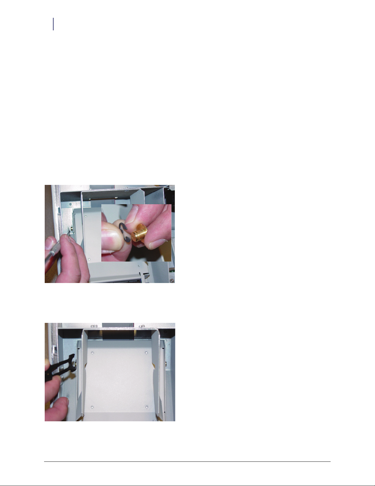
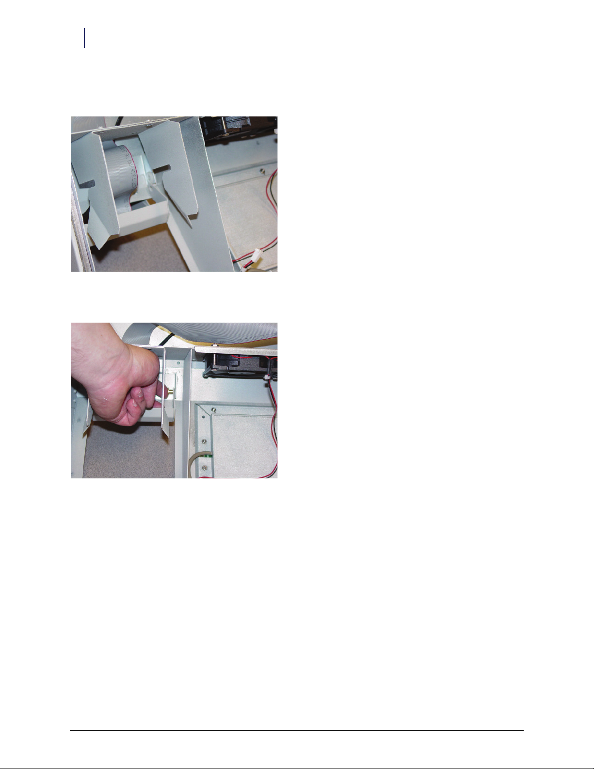
2. Use a scribe to rotate the e-ring on either side of the printer lid, so that the opening is in the front. See close-
up for relative position to brass pivot. Right side e-ring not shown.
Figure 1-2. Rotating the E-rings
3. Push the e-ring off of the brass pivot on either side of the printer lid. The optional e-ring installation tool may
be used for this step.
Figure 1-3. Removing the E-rings
Omnicell/OptiFlex Card Reader Installation and Configuration Guide/67-2006 Rev G © 2010 Omnicell, Inc.
Page 9
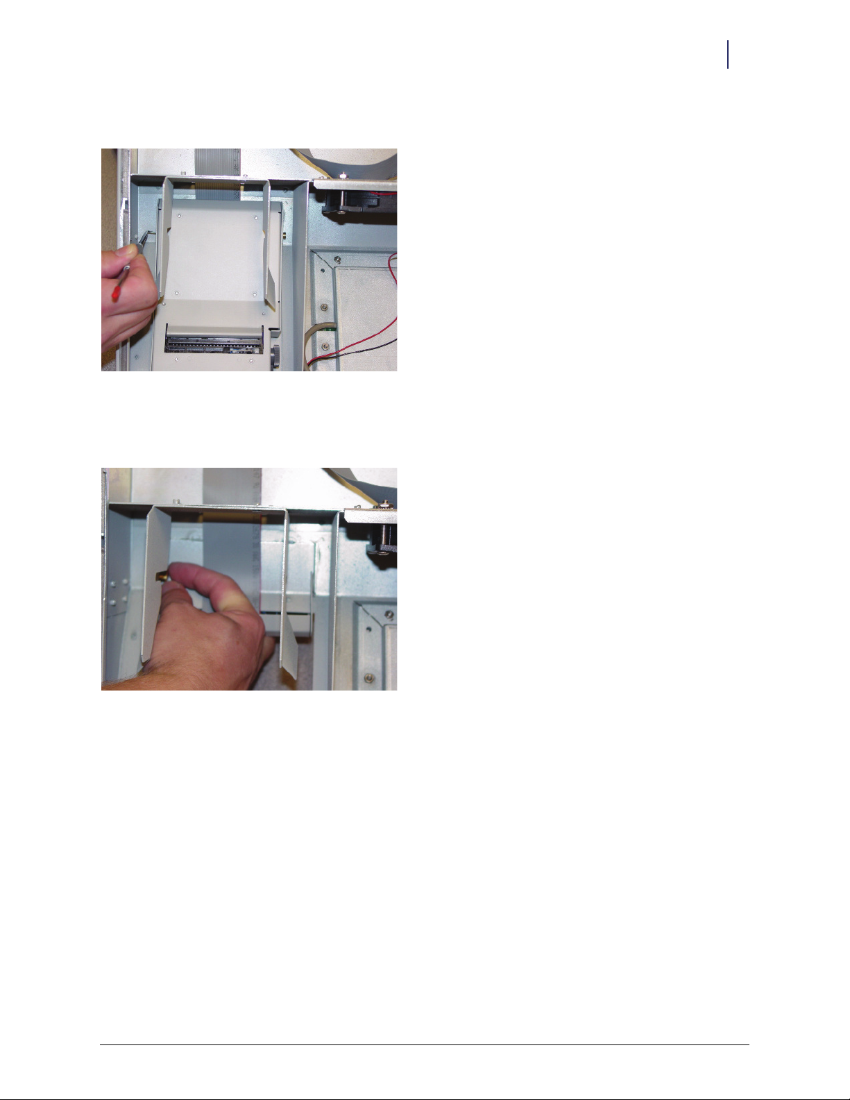
4. Push in the two brass pivots until no longer visible.
Figure 1-4. Pushing in the brass pivots
5. Lift the cabinet lid slightly, then rotate the printer lid to the open position
6. Remove the brass pivots, and set aside.
Hardware Installation 1-5
Retrofit Instructions
Figure 1-5. Removing the brass pivots
7. Free the printer cable from any clips.
© 2010 Omnicell, Inc. Omnicell/OptiFlex Card Reader Installation and Configuration Guide/67-2006 Rev G
Page 10
1-6 Hardware Installation
Retrofit Instructions
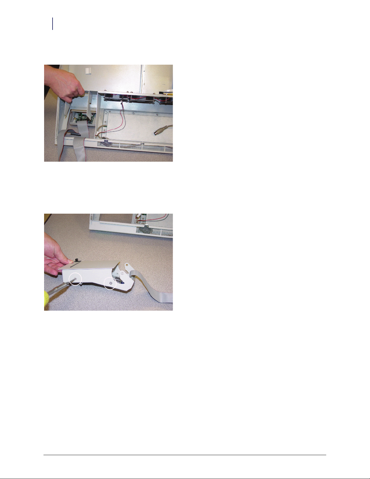
8. Slide the printer out and remove from the cabinet lid.
Figure 1-6. Removing the printer
Installing the Card Reader
1. Use the T-10 Torx driver to remove the four 6-32 flat head screws securing the printer lid (two on either side
of the printer assembly).
Figure 1-7. Removing the printer lid
2. Separate the lid from the printer assembly and discard the lid.
Omnicell/OptiFlex Card Reader Installation and Configuration Guide/67-2006 Rev G © 2010 Omnicell, Inc.
Page 11
Hardware Installation 1-7
Retrofit Instructions
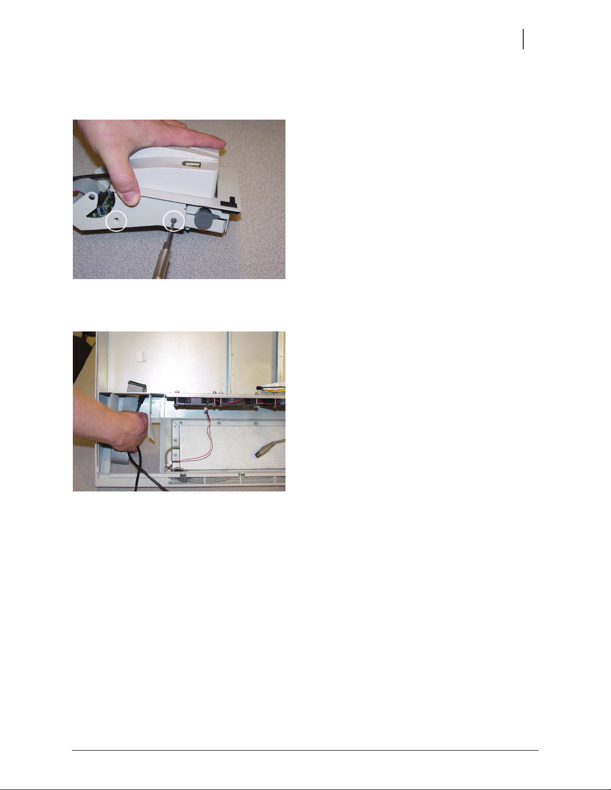
3. Install the card reader to the printer assembly (mounting replaces printer lid), using the four screws removed
in Step 1.
Figure 1-8. Assembling the card reader to the printer
4. Thread the printer cables through the cabinet lid, (from outside, in) and behind the console printer housing.
Figure 1-9. Routing the cables
© 2010 Omnicell, Inc. Omnicell/OptiFlex Card Reader Installation and Configuration Guide/67-2006 Rev G
Page 12
1-8 Hardware Installation
Retrofit Instructions
5. Install the printer/card reader assembly to the cabinet lid, aligning it with the slots in the printer bracket, as
shown.
Figure 1-10. Re-installing the printer assembly with the Touch & Go device
6. Insert the two brass pivots removed earlier.
Figure 1-11. Installing the brass pivots
Omnicell/OptiFlex Card Reader Installation and Configuration Guide/67-2006 Rev G © 2010 Omnicell, Inc.
Page 13
Hardware Installation 1-9
Retrofit Instructions
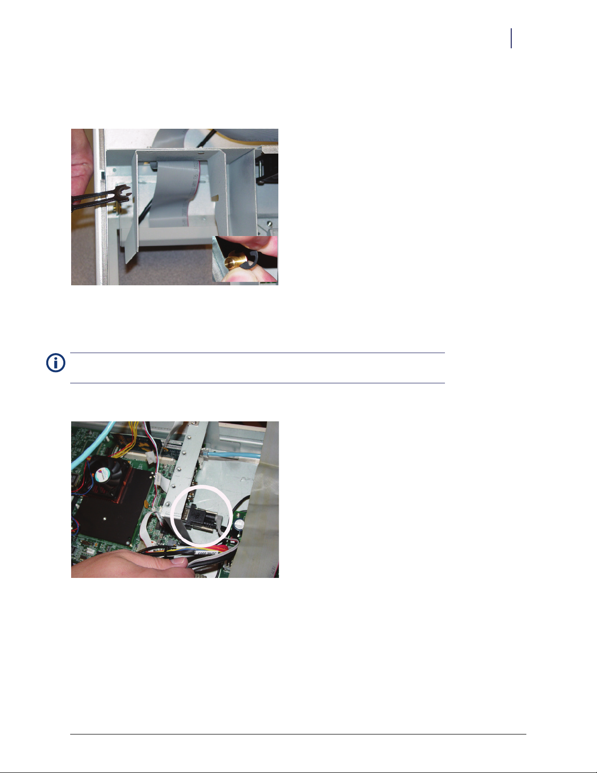
7. Secure each brass pivot with an e-ring, using the e-ring installation tool as shown.- Position the e-ring with
the opening facing the cabinet lid (opposite of removal procedure). See close-up for relative position to brass
pivot.
Figure 1-12. Installing the E-rings
8. Secure the printer cable into available clip(s) on the cabinet lid.
9. Replace the cabinet lid and reconnect the cables.
Note:
For detailed cable placement instructions, see the Color Touch ETX Electronics Tray Installation
Instructions (Doc P/N #60-8019).
10. Connect card reader serial cable to J47 on the ETX motherboard.
Figure 1-13. Connecting the serial cable
11. Connect card reader power cable to the back of the card reader serial connector.
© 2010 Omnicell, Inc. Omnicell/OptiFlex Card Reader Installation and Configuration Guide/67-2006 Rev G
Page 14

1-10 Hardware Installation
Retrofit Instructions
12. Insert card reader power cable pins into the disk drive power connector. Align the red-stripe pin to the red
cable and the gray-stripe pin to the next spot.
Figure 1-14. Connecting the power cable pins
Note:
For connecting power cable to SATA drives, see “Sleds with SATA Drive” on page 1-18.
13. Remove the ESD wristband.
Final Procedures
1. Secure the electronics sled.
2. Connect the power, turn on the cabinet, and reboot the cabinet software.
3. Log into the cabinet (as Omnitech or other authorized User Type).
4. Proceed to “Software Configuration” on page 2-1.
ColorTouch / OptiFlex Tall Cabinets
The cabinet hardware is the same for Color Touch and OptiFlex. The difference is the software and user
interface. There is also a difference in configuring/activating the card reader. For Color Touch cabinets, see
“Color Touch” on page 2-1. For OptiFlex cabinets, see “OptiFlex” on page 2-7.
Tools Required
T-10 Torx Driver
ESD Wrist Strap
Preparing the Cabinet
1. Perform a graceful shutdown of the cabinet software, then power down the cabinet and disconnect power
cord.
2. Slide the PC box forward and remove the lid.
Caution: Put on a grounded ESD wristband before working on the PC box.
Omnicell/OptiFlex Card Reader Installation and Configuration Guide/67-2006 Rev G © 2010 Omnicell, Inc.
Page 15
Hardware Installation 1-11
Retrofit Instructions
Removing PC Box Bezel
1. If a card reader is currently installed, disconnect the card reader serial and power cable.
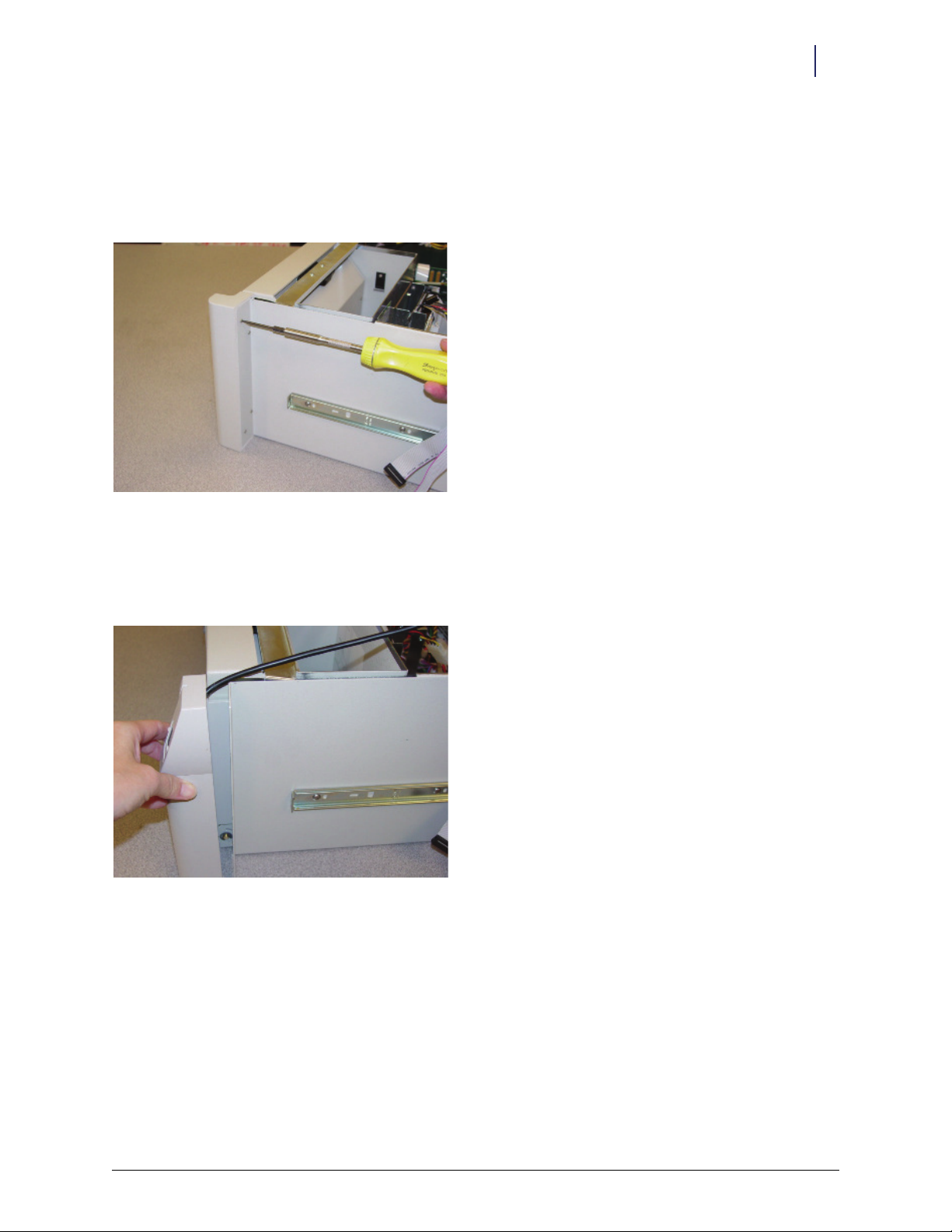
2. Use a T-10 Torx driver to remove the four screws that secure the existing PC box bezel. Remove the bezel and
discard it.
Figure 1-15. Removing the PC box bezel
Installing the Card Reader
1. Align the new bezel with the car reader, then secure it to the PC box using the four screws previously
removed.
Figure 1-16. Installing new bezel
2. Route the card reader cable between the PC box sidewall and printer housing.
3. Route the cable(s) neatly in the PC box using the cable ties/kurly locks provided in the kit as needed.
© 2010 Omnicell, Inc. Omnicell/OptiFlex Card Reader Installation and Configuration Guide/67-2006 Rev G
Page 16
1-12 Hardware Installation
Retrofit Instructions
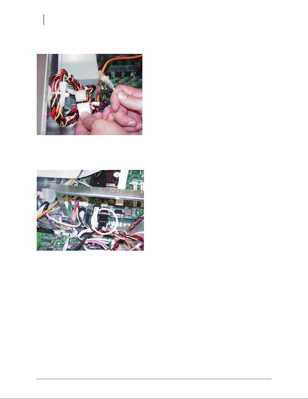
4. Connect the card reader power cable provided in the kit to the PC box power supply cable.
Figure 1-17. Connecting the power cable
5. Connect the card reader serial cable to the serial port.
6. Connect the power cable to the back of the serial cable connector.
Figure 1-18. Connecting the serial cable
7. Remove the ESD wristband.
Final Procedures
1. Close the PC box lid and slide the PC box back into the cabinet.
2. Connect the power, turn on the cabinet, and reboot the cabinet software.
3. Log into the cabinet (as Omnitech or other authorized User Type).
4. Proceed to “Software Configuration” on page 2-1.
Omnicell/OptiFlex Card Reader Installation and Configuration Guide/67-2006 Rev G © 2010 Omnicell, Inc.
Page 17

Hardware Installation 1-13
Retrofit Instructions
Anesthesia Workstation (AWS)
The card reader is attached to the side of the AWS keyboard. The cables get routed through the keyboard bracket
cutout and LCD bezel into the electronic sled.
Note: if replacing like assemblies, testing the new unit with the existing cables may save time, prior to
removing the LCD bezel and replacing the cables.
Tools Required
T-10 Torx Driver
ESD Wrist Strap
Preparing the Cabinet
1. Login to the Administration menu.
2. Press the Exit To Shell button.
3. Press OK on the confirmation window.
4. Press the Shutdown On Exit radio button in the Exit the Shell section.
5. Press the Exit The Shell button.
Note: Wait for the screen to display: “It is now safe to turn off this OmniCT.”
6. Switch the power off in the back of the station.
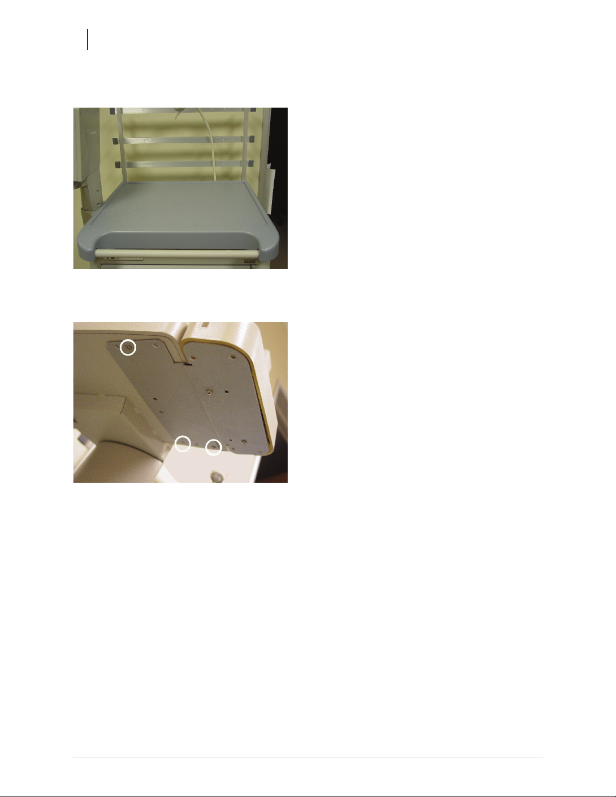
7. Remove the 16 LCD bezel cover screws using a T-10 Torx driver.
Figure 1-19. Removing the LCD bezel
© 2010 Omnicell, Inc. Omnicell/OptiFlex Card Reader Installation and Configuration Guide/67-2006 Rev G
Page 18
1-14 Hardware Installation
Retrofit Instructions
8. Unlock, then lift the sled top and pull it forward. Lift it up and set it aside.
Figure 1-20. Accessing the electronic sled
9. Remove the 3 screws that attach the reader bracket to the keyboard-LCD bracket.
Figure 1-21. Removing the current reader, if present
Omnicell/OptiFlex Card Reader Installation and Configuration Guide/67-2006 Rev G © 2010 Omnicell, Inc.
Page 19
Hardware Installation 1-15
Retrofit Instructions
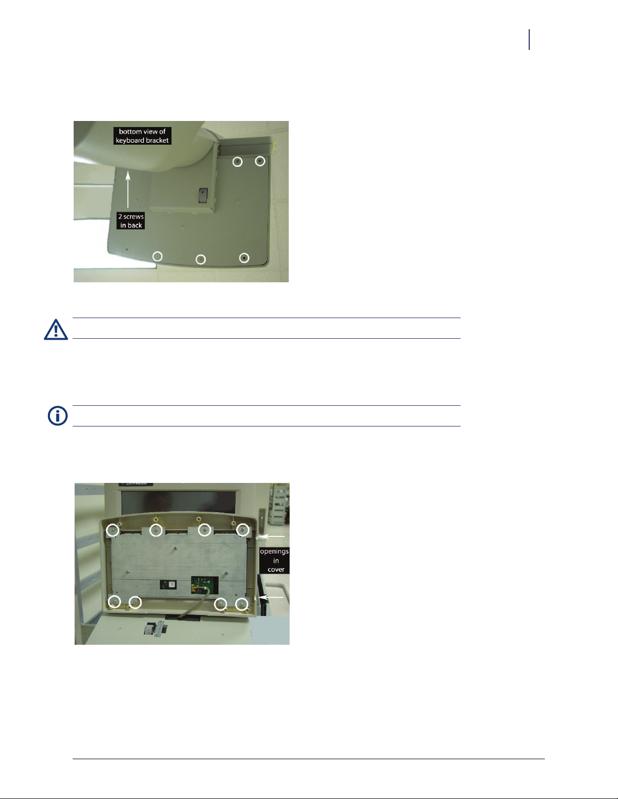
10. Remove the 5 remaining screws from the keyboard-LCD bracket. If there is no reader bracket, all 8 screws
need to be removed.
Figure 1-22. Accessing the keyboard assembly
Caution: Put on a grounded ESD wristband before working on the electronic sled.
Installing the Card Reader
1. Disconnect the cable(s) inside the electronic sled, remove the cable(s), and set the old assembly aside.
Note: If the existing keyboard bezel is in good shape, skip to Step 4.
2. Remove the eight keyboard base (84 key to bezel bracket) screws to take off the existing keyboard bezel.
3. Secure the keyboard base to a new keyboard bezel.
Figure 1-23. Securing the new keyboard bezel
© 2010 Omnicell, Inc. Omnicell/OptiFlex Card Reader Installation and Configuration Guide/67-2006 Rev G
Page 20
1-16 Hardware Installation
Retrofit Instructions
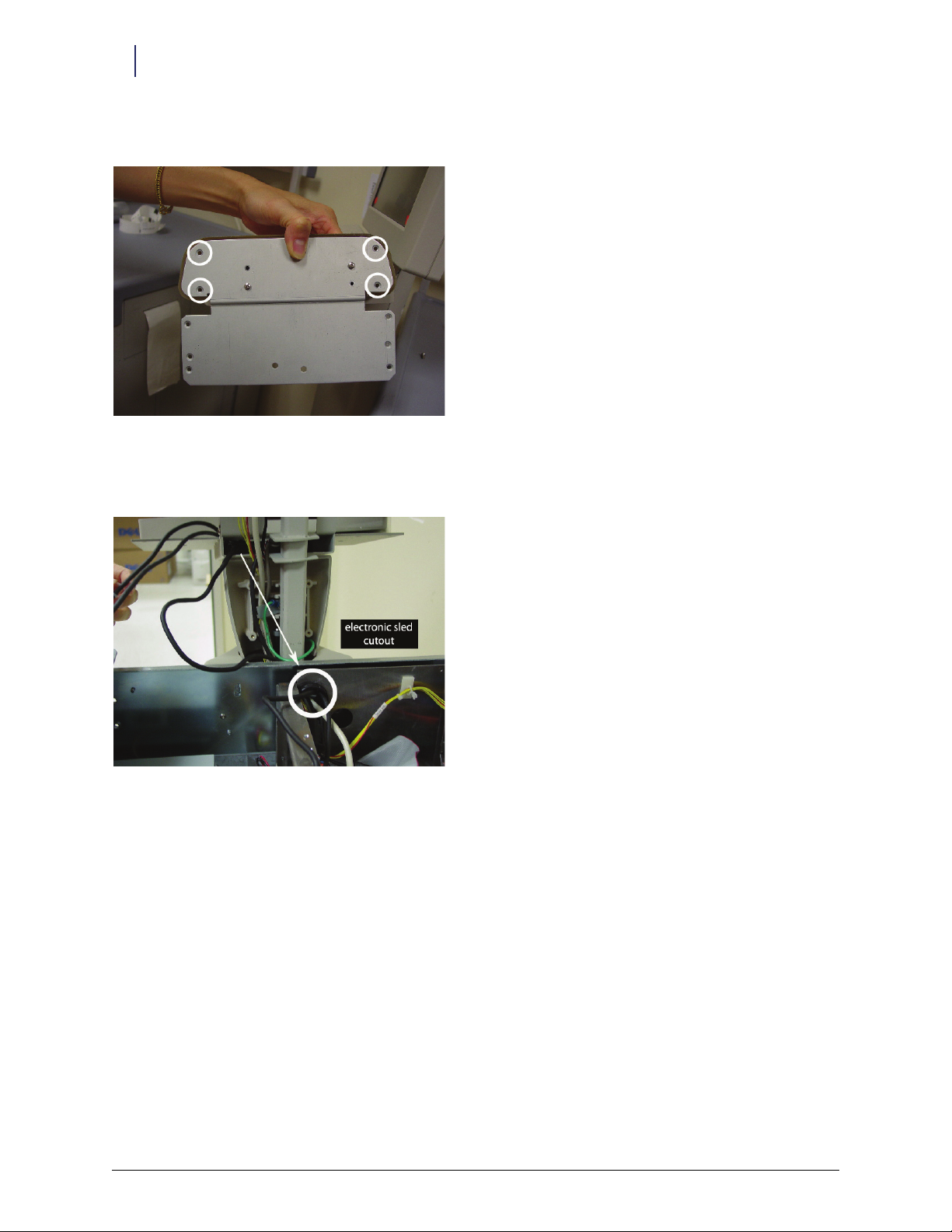
4. Remove the 4 corner reader bracket screws to take off the new reader bezel.
Figure 1-24. Accessing the reader assembly
5. Route the mag card reader or bar code scanner cable from the reader assembly through the keyboard bracket
cutout and LCD bezel into the electronic sled.
Figure 1-25. Routing cables through bezel into electronic sled
6. Secure the reader bezel to the reader bracket.
7. Route the USB reader cable through the back keyboard opening.
8. Secure the keyboard assembly to the keyboard bracket. Leave three screw holes open on the right side (one in
front, two in back)--where the reader bracket is placed.
9. Secure the reader bracket to the keyboard bracket using three 6-32 x 3/8 flat head Torx screws. Refer to
Figure 1-21 on page 1-14.
10.Re-install the LCD bezel.
Omnicell/OptiFlex Card Reader Installation and Configuration Guide/67-2006 Rev G © 2010 Omnicell, Inc.
Page 21

Hardware Installation 1-17
Retrofit Instructions
Electronic Sled Configuration
1. Connect the 4-pin female end of the CD ROM power cable to the male end of the power adapter Y- ca bl e.
Figure 1-26. Splitting the CD-ROM power for the fingerprint scanner
2. Connect the 8-pin male end of the CD ROM power cable to the Powercom board if it is not already.
3. Connect one of the female ends of the Y-cable to the male end of the reader power cable.
Figure 1-27. Relaying power to the fingerprint scanner
4. Connect male molex connector of the card reader power cable to card reader (mag card or bar code) if it is
not already.
5. If the sled does not have a SATA drive, skip to “Sleds without SATA Drive” on page 1-19.
© 2010 Omnicell, Inc. Omnicell/OptiFlex Card Reader Installation and Configuration Guide/67-2006 Rev G
Page 22

1-18 Hardware Installation
Retrofit Instructions
Sleds with SATA Drive
1. Connect the female connector of the SATA cable to the SATA drive.
2. Connect the remaining power adapter Y-cable’s female connectors to the SATA cable male connectors.
Figure 1-28. Sled configuration with SATA drive
Figure 1-29. Connecting hard drive, powercom, and reader
3. Skip to “Final Procedures” on page 1-20.
Omnicell/OptiFlex Card Reader Installation and Configuration Guide/67-2006 Rev G © 2010 Omnicell, Inc.
Page 23

Sleds without SATA Drive
1. Connect the remaining open female end of the Y-cable into the CD ROM (IDE drive).
Figure 1-30. Returning power to the CD-ROM
2. Connect the (mag card reader or bar code scanner) USB cable into the USB port.
Hardware Installation 1-19
Retrofit Instructions
Figure 1-31. Securing the magnetic card reader or bar code scanner cable connection
© 2010 Omnicell, Inc. Omnicell/OptiFlex Card Reader Installation and Configuration Guide/67-2006 Rev G
Page 24

1-20 Hardware Installation
Retrofit Instructions
Final Procedures
1. Remove the ESD wristband.
2. Replace the sled top.
Figure 1-32. Completed Replacement
3. Turn on the power switch in the back of the cabinet.
4. Reboot the Color Touch software.
5. Log into the cabinet (as Omnitech or other authorized User Type).
6. Proceed to “Software Configuration” on page 2-1.
Omnicell/OptiFlex Card Reader Installation and Configuration Guide/67-2006 Rev G © 2010 Omnicell, Inc.
Page 25

2-1
Software Configuration
Card readers can be used with various Color Touch cabinets and with OptiFlex cabinets. The configuration
procedures vary for the different software systems.
Color Touch
Feature Overview
The Magnetic Identification Card Reader has been enhanced with additional configuration options. This allows
Omnicell customers to configure their system for more complex magnetic card types. There are four Card
Reader types. Type 0 is the default reader type. Type 1 is the standard card reader. Types 2-4 are customized for
the varying needs of customer sites.
There are two modes to determine the validity of a user; User ID mode, and Card ID mode. These modes control
how a user is prompted to gain access to a Color Touch. In Card ID Mode, when an ID is entered that does not
match the CARD_ID entry (Mag Card ID) in the Users database, an Invalid Card Usage warning is generated to
the OmniCenter.
In addition, facilities have the option to require magnetic User ID Card-swipe for user login and witness
functions. This option is referred to as Card Only Positive ID. If enabled, users must swipe a valid User ID Card,
then type in a unique password. The user will not be able to enter his/her User ID via the console keyboard.
Functionality/Implementation Options
Software implementation for this feature requires the following general steps:
At the OmniCenter:
1. If using Card ID mode, populate the Mag Card ID field in the Users table for each applicable user. See
“OmniCenter Requirements” on page 2-4.
At the Color Touch cabinet (via Omni Config):
1. Designate the Card Mode (User ID or Card ID).
2. If using Card Only Positive ID, enable Card Only Positive ID mode (Card Only User Login/Witness option).
3. Designate the Card Reader Type.
4. Enter the applicable Card Reader Settings (Pre-skip and Post-skip).
User ID/Card ID Mode
User ID Entry Mode can be set to either User ID (default) or Card ID. If set to User ID, the standard User ID
lookup is performed.
If User ID Entry Mode is set to Card ID, then an alternate user ID lookup will be performed. Any User ID
entered by either the keyboard or mag card reader will be checked against the Mag Card ID field in the user’s
database record. In this mode, the prompt
© 2010 Omnicell, Inc. Omnicell/OptiFlex Card Reader Installation and Configuration Guide/67-2006 Rev G
Enter Card ID displays on all login and witness ID entry windows.
Page 26

2-2 Software Configuration
Color Touch
The Mag Card ID field is an alternate ID for the user that can be set at the server on the user information page.
This allows enhanced security where users can be restricted from knowing their Mag Card ID and be required to
swipe their card to log on.
If a mag card is lost, a new card can be assigned and a new Mag Card ID value set at the server without changing
the user’s User ID.
Card Only Positive ID
If the Card Only User Login/Witness configuration option is enabled, the user logs into the cabinet and/or
provides witness information by swiping a valid User ID Card. A password is then entered using the console
keyboard.
Even with this option is enabled, Omnitech users can still log in manually to access cabinet administration and
maintenance functions. However, they will not have access to Patient Care functions. Omnitech users must
swipe a valid User ID Card for witness purposes.
If the user attempts to enter their User ID via the keyboard (for login or witness), the following warning displays:
User ID Card required for login and witness. Please use your User ID Card.
Card Reader Types
Type 0
The entire card data is treated as the User ID. This is the default type.
Type 1
Type 1 extracts one specific part of the mag card data as the User ID. The data is broken into three parts:
Pre-Skip: specified number of characters to skip from the first card data character before reading starts
Read: the number of characters to read for the User ID
Post Skip: number of characters to skip after the User ID to the last card data character; this number must be
greater than 0
If the number of characters on the card equal the total number specified for Pre-Skip, Read, and Post-Skip, the
characters read and stored are treated as the User ID. Otherwise, the card swipe is ignored.
The User ID and mag card data are fixed width. The User ID size and the total amount of characters on all cards
at the site must be exactly the same.
Type 2
Type 2 uses a two-delimiter character search using the equal sign (=).
The card reader data is scanned for two instances of the equals sign(=). If two instances of the delimiter cannot
be found, the card swipe is ignored.
After the second delimiter, all the characters up to the end of the card are read and stored as the User ID. One to
twelve alphanumeric characters must be read (not counting colons) or the card swipe is ignored.
The User ID and mag card data do not have to be fixed width. Because a delimiter search is used, the User ID
and the total amount of characters on all cards at the site can vary.
Omnicell/OptiFlex Card Reader Installation and Configuration Guide/67-2006 Rev G © 2010 Omnicell, Inc.
Page 27

Software Configuration 2-3
Color Touch
Type 3
Type 3 processing extracts two specific parts of the mag card data and combines them into the User ID. The data
is broken into five parts:
Pre-Skip: specified number of characters to skip from the first card data character before reading starts
Read: the number of characters to read for the first part of the User ID
Secondary Skip: number of characters to skip between reads
Secondary Read: the number of characters to read for the second part of the User ID
unused: any characters remaining in the card data after the Secondary Read are ignored.
The characters from the two reads are combined and treated as a User ID. The number of characters specified by
Read and Secondary Read must total 12 or less.
Type 3 requires the User ID to be a fixed width. The placement of the ID is also fixed. The User ID size and the
placement of data on all cards at the site must be exactly the same. However, the total width (number of
characters) of the mag card data is not fixed.
Type 4
Type 4 uses a single delimiter character search, and extracts characters in front of the delimiter. The delimiter
character to search for is set by the Delimiter Character configuration option. This option defaults to the equals
sign (=).
The card reader data is scanned for the first instance of the delimiter character. If the delimiter is not found, the
card swipe is ignored.
Precede Characters: number of characters to read for the User ID working backwards from the delimiter
towards the start of the data
unused: any characters after the delimiter or extra characters between the first card data character and the
last character of the reverse read
If the number of alphanumeric characters read is less than what was specified by Precede Characters, the card
swipe is ignored. Any extra characters at the start of the card data or after the delimiter is ignored.
Type 4 requires the User ID be fixed width and the placement of the ID to be fixed with respect to the delimiter.
However, the total width of the mag card data is not fixed. Data before and after the captured ID is ignored.
© 2010 Omnicell, Inc. Omnicell/OptiFlex Card Reader Installation and Configuration Guide/67-2006 Rev G
Page 28

2-4 Software Configuration
Color Touch
OmniCenter Requirements
If the card reader is set to User ID mode, the card swipe is validated against the User ID field of the User record
in the OmniCenter Users table. If the User IDs and card readers are configured properly, no additional
implementation steps are required at the OmniCenter.
If the card reader is set to Card ID mode, the card swipe is validated against the Mag Card ID field of the User
record in the OmniCenter Users table. If this field is not already populated, a valid Mag Card ID must be entered
for each user.
Figure 2-1. Database Tab of the Users Table / Mag Card ID Field in a User Record
Cabinet Configuration Options
Config Name <USERS>
Menu Name User ID Entry Mode Options
Description Determines whether the ID derived from the mag card or typed in at the keyboard is checked
against the entry in the USER_ID or CARD_ID field in the database Users table.
Values USER_ID, CARD_ID.
Default USER_ID
Omnicell/OptiFlex Card Reader Installation and Configuration Guide/67-2006 Rev G © 2010 Omnicell, Inc.
Page 29

Software Configuration 2-5
The following configuration options are found under the User ID Card Options submenu.
Config Name <CARD READER>
Menu Name Card Reader Type
Description Enables User ID card support and specifies the type.
Values USER_ID, CARD_ID.
De fau lt N one, Type 1, Ty pe 2 , Typ e 3, Typ e 4
Config Name <CARD READER>
Menu Name Card Only User Login/Witness
Description If enabled, a User ID Card is required for login and witness functions. Omnitech users can login
manually, but will not have access to the Patient Care functions (Blue Screen). All users, including
Omnitech, are required to swipe a valid User ID Card for witness purposes.
Values Enable, Disable
Default Disable
The following configuration options are found under the User ID Card Options, Card Settings submenu.
Color Touch
Config Name <CARD READER>
Menu Name Card Reader Pre-Skip Characters
Description For Type 1 & 3 card reader: number of characters to skip at the start of the card data.
Values 0-1024
Default 0
Config Name <CARD READER>
Menu Name Card Reader Post-Skip Characters
Description For Type 1 card readers: the number of characters to ignore at the end of the card
Values 0-1024
Default 0
Config Name <CARD READER>
Menu Name Card Reader Read Characters
Description For Type 1 & 3 card reader: number of characters to read after the first skip block
Values 0-12
Default 0
© 2010 Omnicell, Inc. Omnicell/OptiFlex Card Reader Installation and Configuration Guide/67-2006 Rev G
Page 30

2-6 Software Configuration
Color Touch
Config Name <CARD READER>
Menu Name Card Reader Secondary Skip Characters
Description For Type 3 card reader: number of characters to skip after the first read block
Values 0-1024
Default 0
Config Name <CARD READER>
Menu Name Card Reader Secondary Read Characters
Description For Type 3 card reader: number of characters to read after the second skip block
Values 0-1024
Default 0
Config Name <CARD READER>
Menu Name Card Reader Precede Characters
Description For Type 4 card reader: number of characters to read preceding the delimiter.
Values 0-12
Default 0
Config Name <CARD READER>
Menu Name Card Reader Delimiter Character
Description For Type 4 card reader: search delimiter character
Values Any keyboard value
Default =
Omnicell/OptiFlex Card Reader Installation and Configuration Guide/67-2006 Rev G © 2010 Omnicell, Inc.
Page 31

OptiFlex
Setting Card Reader Options
1. Select Hospital Setup Params from the ICM Main Menu.
Software Configuration 2-7
OptiFlex
2. Click on the Global tab in the Hospital Setup window.
© 2010 Omnicell, Inc. Omnicell/OptiFlex Card Reader Installation and Configuration Guide/67-2006 Rev G
Page 32

2-8 Software Configuration
OptiFlex
3. Enter the reader option values.
Default
Parameter Description Possible Values
Strip Leading Zeroes Removes leading zeroes from the User ID data Enabled/Disabled Disabled
Port Time-out Release port after milliseconds of inactivity 25-99 50
Read Type See “Card Reader Types” on page 2-2. 0-4 0
Pre-Read Length For Type 1 & 3 card reader: number of characters to skip at the start of the card data. 0-99 0
Read Length For Type 1 & 3 card reader: number of characters to read after the first skip block 0-99 0
Post Read Length For Type 1 & 3 card reader: the number of characters to ignore at the end of the card 0-99 0
Sec(ondary) Read Length For Type 3 card reader: number of characters to read after the second skip block 0-99 0
Precede Length For Type 4 card reader: number of characters to read preceding the delimiter. 0-99 0
Delimiter For Type 2 & 4 card reader: search delimiter character Any keyboard character =
Ignore For Type 2 card reader: character to not count Any keyboard character :
Value
Table 2-1. Card Reader Options
4. Click Save Changes.
5. Type MM on the Medical Surgical, Surgical Supplies, or Procedures module window.
Omnicell/OptiFlex Card Reader Installation and Configuration Guide/67-2006 Rev G © 2010 Omnicell, Inc.
Page 33

Software Configuration 2-9
OptiFlex
6. Select Station Settings from the Maintenance section of the Materials Management main menu. A login
window is displayed.
7. Type in the proper login information, then click OK or Enter.
© 2010 Omnicell, Inc. Omnicell/OptiFlex Card Reader Installation and Configuration Guide/67-2006 Rev G
Page 34

2-10 Software Configuration
Mag Card Reader
8. Click on the Hardware tab of the Station Setup window.
9. Click on the Card Reader Enabled box if it is not already marked.
Note:
The Reader Com Port value is preset to 3. Check with IT for the proper value (1-4) if a change is needed.
10. Click Save Changes and Return to Main Menu.
Mag Card Reader
Specifications
The magnetic card reader should conform to the ISO 7811 1-5 Standard.
Formats: ISO 7811, AAMVA, and CA DMV
Tracks: 1, 2, 3
Omnicell/OptiFlex Card Reader Installation and Configuration Guide/67-2006 Rev G © 2010 Omnicell, Inc.
Page 35

Software Configuration 2-11
Mag Card Reader
XP Window Base Setup
This procedure was formerly done in manufacturing, but can now be done in the field.
1. On the CT or PC Box screen, click on Exit to Shell icon.
2. Click OK on the confirmation window.
3. In the Exit the Shell window, click Just Quit on Exit in the lower right corner, then click Exit the Shell.
4. Enter the proper user ID and password, then click Enter. The application exits to MS-Window XP desktop
screen.
5. Got to: Start > Programs > Accessories > Communications > Hyper Terminal. The New Connection - Hyper Terminal
window is displayed with Connection Description.
Figure 2-2. New Connection/Hyper Terminal window
6. Click OK in the Connection Description window.
7. Type in a New Connection name. Use a reference to the customer site. (Example: Baptist)
8. Click OK. The Connection Description window closes and the New Connection - Hyper Terminal window
connects to the specified Hyper Terminal window.
© 2010 Omnicell, Inc. Omnicell/OptiFlex Card Reader Installation and Configuration Guide/67-2006 Rev G
Page 36

2-12 Software Configuration
Mag Card Reader
9. Click on File in the upper left corner of the Hyper Terminal window, then select Properties from the drop-
down menu. The Properties window is displayed.
Figure 2-3. Properties window
10. Click the Connect To tab and make the following entries:
Country/Region: Set to United States of America (1).
Area Code: Type the site’s Area Code.
Phone Number: Set to Open.
Connect Using: Set to COM3.
Check the Use country/region code and area code option.
Uncheck the Redial on busy option.
Omnicell/OptiFlex Card Reader Installation and Configuration Guide/67-2006 Rev G © 2010 Omnicell, Inc.
Page 37

11. Click on Setting tab and make the following entries:
Software Configuration 2-13
Mag Card Reader
Figure 2-4.
Under Function, Arrow, and Control keys act as:
–Check the Terminal keys option.
–Uncheck the Windows keys option.
Under Backspace key sends:
–Check the Ctrl+H option.
–Uncheck the Del and Ctrl+H, Space, Ctrl+H options.
Emulation: Set to Auto detect.
Telnet term inal ID: Set to ANSI.
Backscroll buffer lines: Set to 500.
Uncheck the Play sound when connection or disconnecting option.
© 2010 Omnicell, Inc. Omnicell/OptiFlex Card Reader Installation and Configuration Guide/67-2006 Rev G
Page 38

2-14 Software Configuration
Mag Card Reader
12. Click ASCII Setup and make the following entries:
Figure 2-5.
Under ASCII Sending:
–Uncheck the Send line ends with line feeds option.
–Check the Echo typed characters locally option.
– Line delay: Set to
– Character delay: Set to
Under ASCII Receiving:
0 milliseconds.
0 milliseconds.
–Check the Append line feeds to incoming line ends option.
–Uncheck the Force incoming data to 7-bit ASCII option.
–Check the Wrap lines that exceed terminal width option.
13. Click OK once the ASCII setup complete.
14. Click OK to close the Properties window.
15. Type the following in the Hyper Terminal Window.
a. Type
b. Type
c. Type
/E/D/FA, then press Enter. The computer sounds two short beeps.
AW, then press Enter. The computer sounds two short beeps.
AZ, then press Enter. The computer sounds three short beeps.
16. Click on File drop down menu in the top left of the window, then select Save.
17. Click on File drop down menu in the top left of the window, then select Exit.
Omnicell/OptiFlex Card Reader Installation and Configuration Guide/67-2006 Rev G © 2010 Omnicell, Inc.
Page 39

Configuration
1. Double click on the OmniCT icon on the MS-Window XP desktop.
2. Click Start Now.
3. Type in the proper user ID and password, then click Enter.
4. Click on OmniConfig, then select Card Reader.
5. Select Hardware Setting, then make the following entries.
Select Card Reader Band Rate.
a. Set to
b. Click Update.
c. Click Previous Screen.
Select Card Reader Flow Control.
a. Set to
b. Click Update.
c. Click Previous Screen.
Select Card Reader Post.
a. Set to
b. Click Update.
c. Click Previous Screen.
Select Card Reader Timeout.
a. Set to
b. Click Update.
c. Click Previous Screen.
6. Select Patient ID, then make the following entries.
Select Patient ID Card Mode.
a. Set to
b. Click Update.
c. Click Previous Screen twice.
7. Select User ID Card, then make the following entries.
Select Card Only User Login/Witness.
a. Set to
b. Click Update.
c. Click Previous Screen.
Select Card Reader Type.
a. Set to
b. Click Update.
c. Click Previous Screen twice.
9600.
Disable.
COM3.
50.
Instant.
Disable.
Typ e 1.
Software Configuration 2-15
Mag Card Reader
© 2010 Omnicell, Inc. Omnicell/OptiFlex Card Reader Installation and Configuration Guide/67-2006 Rev G
Page 40

2-16 Software Configuration
Mag Card Reader
Verification
1. Go to: OmniConfig > Card Reader > Hardware Setting if not already there.
2. Select Test Card Read er.
3. Swipe the test card. The screen should display the card number—a maximum of 12 to 17 characters.
(Example:
4. Record the screen display in a note.
5. Click Previous Screen.
;00013262201111?[])
Track 1 Programming
1. Go to OmniConfig > Card Reader > Hardware Setting if not already there.
2. Select Card Setting, then make the following entries.
Note:
There is no setting for Card Reader Delimiter Characters =.
Select Card Reader Pre Skip Characters.
a. Set New Value to
b. Click Update.
c. Click Previous Screen.
Select Card Reader Post Skip Characters.
a. Set New Value to
b. Click Update.
c. Click Previous Screen.
Select Card Reader Read Characters.
a. Set New Value to
b. Click Update.
c. Click Previous Screen.
Select Strip Leading Zeros.
a. Set Current Value to
b. Click Update.
c. Click Previous Screen.
4.
2.
11.
No.
Note: There is no setting for Verify Card ID.
3. Select User IS Wizard.
4. Type in the ID
5. Swipe the card into the badge reader slot.
6. Click Previous Screen twice to exit back to the Hardware Setting window.
7. Select Test Card Read er.
8. Swipe the card. The card number is displayed on the card reader data screen [13262201111].
Omnicell/OptiFlex Card Reader Installation and Configuration Guide/67-2006 Rev G © 2010 Omnicell, Inc.
13262201111.
Page 41

Software Configuration 2-17
Bar Code Card Reader
9. If the system can not read the test card, restart the process from “XP Window Base Setup” on page 2-11.
10. Click Exit to go to top menu window.
Bar Code Card Reader
Card Specifications
Read Height: .400" (1cm)
Centerline of barcode should be .400” from the bottom of the card. A minimum of a quarter inch
Note:
spacing is required between the edge of the card and the code.
Card width
Bar code media: .005" to .055"
Magnetic stripe media: .01" to .055"
Max card thickness: .055"/.050"
Bar Code Print Quality
Standard, high-resolution scanners required a height minimum of 10 mils.
Infrared bar codes should be readable at the 940nm wavelength. This requires the use of carbon content ribbons
for dot matrix printers.
Print quality must comply with ANSI standards. Grade C is the minimum acceptable level to enable the
averaging process to work. For more details, refer to The Layman’s Guide to ANSI, CEN, and ISO Barcode Print
Quality Documents.
Bar Code Data Guidelines
Each facility must identify a single software configuration process type to implement. The user ID and bar code
data must be a fixed width. The user ID size and the total amount of data on all cards at the site must be exactly
the same.
© 2010 Omnicell, Inc. Omnicell/OptiFlex Card Reader Installation and Configuration Guide/67-2006 Rev G
Page 42

2-18 Software Configuration
Bar Code Card Reader
Bar Code Formats/Symbologies
Code 39
Interleaved 2 of 5
Industrial 2 of 5
Code 128
Codabar
UPC-A
EAN-13
MSI/Plessy
Te le p a n
UPC-E
EAN-8
XP Window Base Setup
This procedure was formerly done in manufacturing, but can now be done in the field.
1. On the CT or PC Box screen, click on Exit to Shell icon.
2. Click OK on the confirmation window.
3. In the Exit the Shell window, click Just Quit on Exit in the lower right corner, then click Exit the Shell.
4. Enter the proper user ID and password, then click Enter. The application exits to MS-Window XP desktop
screen.
Omnicell/OptiFlex Card Reader Installation and Configuration Guide/67-2006 Rev G © 2010 Omnicell, Inc.
Page 43

Software Configuration 2-19
Bar Code Card Reader
5. Got to: Start > Programs > Accessories > Communications > Hyper Terminal. The New Connection - Hyper Terminal
window is displayed with Connection Description.
Figure 2-6. New Connection/Hyper Terminal window
6. Click OK in the Connection Description window.
7. Type in a New Connection name. Use a reference to the customer site. (Example: Baptist)
8. Click OK. The Connection Description window closes and the New Connection - Hyper Terminal window
connects to the specified Hyper Terminal window.
© 2010 Omnicell, Inc. Omnicell/OptiFlex Card Reader Installation and Configuration Guide/67-2006 Rev G
Page 44

2-20 Software Configuration
Bar Code Card Reader
9. Click on File in the upper left corner of the Hyper Terminal window, then select Properties from the drop-
down menu. The Properties window is displayed.
Figure 2-7. Properties window
10. Click the Connect To tab and make the following entries:
Country/Region: Set to United States of America (1).
Area Code: Type the site’s Area Code.
Phone Number: Set to Open.
Connect Using: Set to COM3.
Check the Use country/region code and area code option.
Uncheck the Redial on busy option.
Omnicell/OptiFlex Card Reader Installation and Configuration Guide/67-2006 Rev G © 2010 Omnicell, Inc.
Page 45

11. Click on Setting tab and make the following entries:
Software Configuration 2-21
Bar Code Card Reader
Figure 2-8.
Under Function, Arrow, and Control keys act as:
–Check the Term inal keys option.
–Uncheck the Windows keys option.
Under Backspace key sends:
–Check the Ctrl+H option.
–Uncheck the Del and Ctrl+H, Space, Ctrl+H options.
Emulation: Set to Auto detect.
Telnet term inal ID: Set to ANSI.
Backscroll buffer lines: Set to 500.
Uncheck the Play sound when connection or disconnecting option.
© 2010 Omnicell, Inc. Omnicell/OptiFlex Card Reader Installation and Configuration Guide/67-2006 Rev G
Page 46

2-22 Software Configuration
Bar Code Card Reader
12. Click ASCII Setup and make the following entries:
Figure 2-9.
Under ASCII Sending:
–Uncheck the Send line ends with line feeds option.
–Check the Echo typed characters locally option.
– Line delay: Set to
– Character delay: Set to
Under ASCII Receiving:
0 milliseconds.
0 milliseconds.
–Check the Append line feeds to incoming line ends option.
–Uncheck the Force incoming data to 7-bit ASCII option.
–Check the Wrap lines that exceed terminal width option.
13. Click OK once the ASCII setup complete.
14. Click OK to close the Properties window.
15. Type the following in the Hyper Terminal Window.
a. Type
b. Type
c. Type
/E/D/FA, then press Enter. The computer sounds two short beeps.
AW, then press Enter. The computer sounds two short beeps.
AZ, then press Enter. The computer sounds three short beeps.
16. Click on File drop down menu in the top left of the window, then select Save.
17. Click on File drop down menu in the top left of the window, then select Exit.
Omnicell/OptiFlex Card Reader Installation and Configuration Guide/67-2006 Rev G © 2010 Omnicell, Inc.
Page 47

Configuration
1. Double click on the OmniCT icon on the MS-Window XP desktop.
2. Click Start Now.
3. Type in the proper user ID and password, then click Enter.
4. Click on OmniConfig, then select Card Reader.
5. Select Hardware Setting, then make the following entries.
Select Card Reader Band Rate.
a. Set to
b. Click Update.
c. Click Previous Screen.
Select Card Reader Flow Control.
a. Set to
b. Click Update.
c. Click Previous Screen.
Select Card Reader Post.
a. Set to
b. Click Update.
c. Click Previous Screen.
Select Card Reader Timeout.
a. Set to
b. Click Update.
c. Click Previous Screen.
6. Select Patient ID, then make the following entries.
Select Patient ID Card Mode.
a. Set to
b. Click Update.
c. Click Previous Screen twice.
7. Select User ID Card, then make the following entries.
Select Card Only User Login/Witness.
a. Set to
b. Click Update.
c. Click Previous Screen.
Select Card Reader Type.
a. Set to
b. Click Update.
c. Click Previous Screen twice.
9600.
Disable.
COM3.
50.
Instant.
Disable.
Typ e 1.
Software Configuration 2-23
Bar Code Card Reader
© 2010 Omnicell, Inc. Omnicell/OptiFlex Card Reader Installation and Configuration Guide/67-2006 Rev G
Page 48

2-24 Software Configuration
Bar Code Card Reader
Verification
1. Go to: OmniConfig > Card Reader > Hardware Setting if not already there.
2. Select Test Card Read er.
3. Swipe the test card. The screen should display the card number—a maximum of 9 to 12 characters. (Example:
00106867[])
4. Record the screen display in a note.
5. Click Previous Screen.
BarCode Card Programming
1. Go to OmniConfig > Card Reader > Hardware Setting if not already there.
2. Select Card Setting, then make the following entries.
Note:
There is no setting for Card Reader Delimiter Characters =.
Select Card Reader Pre Skip Characters.
a. Set New Value to
b. Click Update.
c. Click Previous Screen.
Select Card Reader Post Skip Characters.
a. Set New Value to
b. Click Update.
c. Click Previous Screen.
Select Card Reader Read Characters.
a. Set New Value to
b. Click Update.
c. Click Previous Screen.
Select Strip Leading Zeros.
a. Set Current Value to
b. Click Update.
c. Click Previous Screen.
0.
2.
7.
No.
Note: There is no setting for Verify Card ID.
3. Select User IS Wizard.
4. Type in the ID
5. Swipe the card into the badge reader slot.
6. Click Previous Screen twice to exit back to the Hardware Setting window.
7. Select Test Card Read er.
8. Swipe the card. The card number is displayed on the card reader data screen [0010686].
Omnicell/OptiFlex Card Reader Installation and Configuration Guide/67-2006 Rev G © 2010 Omnicell, Inc.
0010686.
Page 49

Software Configuration 2-25
Bar Code Card Reader
9. If the system can not read the test card, restart the process from “XP Window Base Setup” on page 2-18.
10. Click Exit to go to top menu window.
© 2010 Omnicell, Inc. Omnicell/OptiFlex Card Reader Installation and Configuration Guide/67-2006 Rev G
Page 50

2-26 Software Configuration
Bar Code Card Reader
Omnicell/OptiFlex Card Reader Installation and Configuration Guide/67-2006 Rev G © 2010 Omnicell, Inc.
Page 51

A-1
Appendix A: Part List
Part Cross-reference
The following table links the part mentioned in the text to the related part number and description with a crossreference link back to the procedure where it is used.
Part # Part Name Agile Description Where Used
13-1101-47 PC box bezel screws (contained in) MFG ASSY,PC BOX,OMNISUPPLIER 4.7 “ColorTouch / OptiFlex Tall
14-1106 PC box bezel BEZEL,STD,PC,BOX,SILKSCREENED “ColorTouch / OptiFlex Tall
14-1109
14-1117
14-1199
14-1200
14-1202
14-1203
14-1209
14-1230
14-7005
14-7011
14-1123 printer lid MFG,ASSY,PRINTER,OMNIRX “Omn iRx/OmniTT/H alf Cel l/
14-1139
14-1140
14-1141
14-1142
14-1146
14-1206
14-1207
42-1168 card reader USB cable Mag Card Power Cable Assy
card reader (cabinets) Mag Card Reader, MCR100 (blue supply)
Bar Code Reader BRC 100 .400, keyboard wedge (blue supply)
Mag Card Reader, 3-Trk [OptiFlex compatible]
Bar Code Reader, serial, 490
Bar Code Reader, serial (blue supply)
Bar Code Reader, serial (blue printer)
Mag Card Reader, 75bpi, 1-Trk [OptiFlex compatible
Bar Code Reader, serial, 400
Mag Card Reader, MCR100 (blue printer)
Bar Code Reader BRC 100 .400, keyboard wedge (blue printer)
card reader (sleds) Mag Card Reader, MCR100 (pharmacy)
Bar Code Reader BRC 100 .400, keyboard wedge (pharmacy)
Mag Card Reader, MCR100 (supply)
Bar Code Reader BRC 100 .400, keyboard wedge (supply)
Mini Mag Card Reader
Bar Code Reader, serial (pharmacy)
Bar Code Reader, serial (supply)
Cabinet s”
Cabinet s”
“ColorTouch / OptiFlex Tall
Cabinet s”
Anesthesia TT”
“Omn iRx/OmniTT/H alf Cel l/
Anesthesia TT”
“Electronic Sled
Configuration”
“Electronic Sled
Configuration”
© 2010 Omnicell, Inc. Omnicell/OptiFlex Card Reader Installation and Configuration Guide/67-2006 Rev G
Page 52

A-2 Appendix A: Part List
Part Cross-reference
Part # Part Name Agile Description Where Used
42-1173
42-1209
42-7093
42-8030
42-1210 fan cable CABLE,ASSY,FAN RETROFIT COOLING,OMNIRX “Omn iRx/OmniTT/H alf Cel l/
14-1213
14-1214
14-1215
14-1231
42-1232 powercom ribbon cable CABLE,ASSY,BATTERY,18V,UPS,CT PC BOX,POWERCOM3 “OmniRx/OmniT T/Half Cell/
42-1242 display cable CABLE,ASSY,LVDS,LCD DISPLAY “Omn iRx/OmniTT/H alf Cel l/
42-1204 card reader power cable
card reader serial cable CABLE,ASSY,SERIAL,MAG,CARD,586
CABLE,ASSY,SERIAL,233
CABLE ASSY, SERIAL, EXTENSION, MINIMAG, CARD READER,
OMNIRX
CABLE,ASSY,SERIAL,BAR,CODE,PWR
reader assembly (AWS) Mag Card Reader, 75bpi, 1-Trk
Mag Card Reader, 3-Trk
Bar Code Reader, serial, 490
Bar Code Reader, serial, 400
CABLE,ASSY,POWER,CARD,READER CT,PC,BOX “OmniR x/OmniTT/Hal f Cell/
USB reader cable / USB cable
“Omn iRx/OmniTT/H alf Cel l/
Anesthesia TT”
“ColorTouch / OptiFlex Tall
Cabinet s”
Anesthesia TT”
“A n e s t h e s i a
Workstat i o n ( AWS ) ”
Anesthesia TT”
Anesthesia TT”
Anesthesia TT”
“ColorTouch / OptiFlex Tall
Cabinet s”
“Electronic Sled
Configuration”
“Sleds without SATA Drive”
“A n e s t h e s i a
Workstat i o n ( AWS ) ”
42-1302 keyboard cable CABLE,ASSY,USB KEYBOARD,QWERTY TO MOTHERBOARD,CTPC “Om niRx/Omni TT/Ha lf Cell /
42-6002 power adapter Y-cable CABLE,POWER,ADAPTER,"Y",HD
Anesthesia TT”
“Electronic Sled
Configuration”
42-7025 speaker cable CABLE,ASSY,SPEAKER,OMNIRX “O mniRx/OmniTT /Half Cell/
42-7037 touch screen cable CABLE,ASSY,TOUCHPAD DATA, SERIAL,RXCT “Om niRx/Omni TT/Ha lf Cell /
42-7071 CD ROM power cable CABLE,ASSY,IUPS,TO,HD,SLED
Anesthesia TT”
Anesthesia TT”
“Electronic Sled
Configuration”
42-7088 printer cable CABLE ASSEMBLY, PRINTER, 48" FOLDED, OMNIRX “Omn iRx/OmniTT/H alf Cel l/
51-7046 brass pivot PIVOT,PRINTER,ASSY,OMNIRX “Omn iRx/OmniTT/H alf Cel l/
53-7258 reader bracket BRACKET,FINGERPRINT,CARD READER,ANESTHESIA
Anesthesia TT”
Anesthesia TT”
“A n e s t h e s i a
Workstat i o n ( AWS ) ”
53-7181 keyboard-LCD bracket BKT,KEYBD-LCD,CONSOLE ANESTHESIA
“A n e s t h e s i a
Workstat i o n ( AWS ) ”
56-7020 keyboard bezel BEZEL,KEYBOARD,ANESTHESIA CARD READER, FINGERPRINT,
MACHINED
“A n e s t h e s i a
Workstat i o n ( AWS ) ”
Omnicell/OptiFlex Card Reader Installation and Configuration Guide/67-2006 Rev G © 2010 Omnicell, Inc.
Page 53

Appendix A: Part List A-3
Part Cross-reference
Part # Part Name Agile Description Where Used
57-7068 LCD bezel cover BEZEL,LCD,REAR,CONSOLE ANESTHESIA
“A n e s t h e s i a
Workstat i o n ( AWS ) ”
88-1005 SATA cable CABLE,POWER,SATA,6IN
“Sleds with SATA
Drive”
94-6090 kurly locks CABLE,MOUNT,KURLY,LOK,RICHCO KLB-350A-RT “ColorTouch / OptiFlex Tall
94-6147 LCD bevel cover screws SCREW,BH,TORX,6-32,X,3/8,SS
Cabinet s”
“A n e s t h e s i a
Workstat i o n ( AWS ) ”
94-6162 6-32 flathead screws SCREW,FH,TORX,6-32,X,3/16,100,DEG,C'SINK “OmniRx/Om niTT/ Half Ce ll/
94-6285 e-ring E-RING,7/32,SHAFT,SS “Omn iRx/OmniTT/H alf Cel l/
94-6290 reader bracket screws
keyboard bezel screws
95-6007 cable tie CABLE,TIE,4 IN. “ColorTouch / OptiFlex Tall
SCREW,PT,PAN,PHILIP,K30-1.34,X,8MM
Anesthesia TT”
Anesthesia TT”
“A n e s t h e s i a
Workstat i o n ( AWS ) ”
Cabinet s”
© 2010 Omnicell, Inc. Omnicell/OptiFlex Card Reader Installation and Configuration Guide/67-2006 Rev G
Page 54

A-4 Appendix A: Part List
Kit Listing
Kit Listing
The following table lists the kits that are used in this document. See “Required Kits” on page 1-2.
Table A-1. Card Reader Kit / Parts List
Kit # Item # Item Description Notes Qty
12-6007 OPTION,KIT,PATIENT,ID,SYSTEM 1
65-6003 MAGNETIC,CARDS,ENCODED,PKG,OF,100 5
65-6004 LABEL,BLANK,2.25,X,1.25 ROLL,OF,1135 2
70-6007 PRINTER,LABEL,TLP-2242 OMNISTOCKROOM/
FLOORSTOCK
71-0004 MAG CARD,READER,KEYBD,INPUT 1
82-6042 CABLE,EXTENSION,DB9,M/F,6 1
14-1109 Mag Card Reader Kit Model MCR 100 / Blue PC Box 1
14-1110 Std PC Box Mag reader Bezel Silk screened 1
42-1168 Mag Card Power Cable Assy 1
53-1027 Mag Card Scratch Plate Bezel Mount 1
71-1055 IDT Mag Card Reader OTI 3820-12 1
94-6208 Screw,PH,PAN,HD,M3,X,5,SS 2
14-1117 Bar Code Reader Kit Model BRC100 1
14-1116 Std PC Box Bar Code Bezel Silk Screened 1
51-1005 Omni Bar Code Bezel Frame 1
71-1041 Bar Code Reader Slot J-IHP 000,000,6RS 1
94-6160 Screw, BH, Torx, 6-32 x 1/2, SS 2
14-1139 OPTION,KIT,MAG,CARD,OMNI-RX for Blue Screen 1
1
42-1168 CABLE,ASSY,POWER,MAG,CARD 1
42-7093 CABLE ASSY, SERIAL, EXTENSION, MINIMAG,
CARD READER, OMNIRX
53-1054 ASSY,PRINTER,DOOR,CARD,READER,OMNIRX 1
71-1055 MAG,CARD,READER,IDT OTI3820-12 1
94-6236 SCREW,TRUSS,HD,TORX,4-40,X,1/4SS 2
14-1140 OPTION,KIT,BAR,CODE,OMNI-RX 1
53-1054 ASSY,PRINTER,DOOR,CARD,READER,OMNIRX 1
71-1041 BAR,CODE,READER,SLOT,J-IHP 000, 000, 6RS 1
94-6208 SCREW,PH,PAN,HD,M3,X,5,SS 2
1
Omnicell/OptiFlex Card Reader Installation and Configuration Guide/67-2006 Rev G © 2010 Omnicell, Inc.
Page 55

Table A-1. Card Reader Kit / Parts List (Continued)
Kit # Item # Item Description Notes Qty
14-1141 OPTION,KIT,MAG,CARD,HALF-CELL 1
42-1168 CABLE,ASSY,POWER,MAG,CARD 1
42-1173 CABLE,ASSY,SERIAL,MAG,CARD,586 1
42-1209 CABLE,ASSY,SERIAL,233 REPLACES, 42-1174,
CABLE, ASSY
42-7093 CABLE ASSY, SERIAL, EXTENSION, MINIMAG,
CARD READER, OMNIRX
53-1055 PLATE,COVER,CARD,READER PRINTER 1
71-1055 MAG,CARD,READER,IDT OTI3820-12 1
94-6208 SCREW,PH,PAN,HD,M3,X,5,SS 2
14-1142 OPTION,KIT,BAR,CODE,HALF-CELL 1
53-1055 PLATE,COVER,CARD,READER PRINTER 1
71-1041 BAR,CODE,READER,SLOT,J-IHP 000, 000, 6RS 1
94-6208 SCREW,PH,PAN,HD,M3,X,5,SS 2
14-1146 Mini Mag Card Kit 3 Track IDT, #OTI, 3321-33 1
14-1110 Std PC Box Mag reader Bezel Silk screened 1
42-1168 Mag Card Power Cable Assy 1
53-1057 Mini Mag Card Scratch Plate 1
71-1073 Mini Mag Reader 3-Track IDT,#OTI,3321-33 1
94-6221 Screw, PH, PAN, HD, M3 x 16, SS Machine Screw A2 2
14-1199 OPTION,KIT,MAG,CARD,3-TRK CT,PC,BOX 1
15-1101 MFG,ASSY,MAG,CARD,3-TRK CT,PC,BOX 1
42-1204 CABLE,ASSY,POWER,CARD,READER CT,PC,BOX 1
42-1209 CABLE,ASSY,SERIAL,233 Replaces 42-1174 Cable Assy 1
65-1058 LABEL,ICON,MAG,CARD 1
95-6007 CABLE,TIE,4,IN. 2
14-1200 OPTION,KIT,BAR,CODE,SERIAL,490CT,PC,BOX 1
15-1102 MFG,ASSY,BAR,CODE,SERIAL,490",CT,PC,BOX 1
42-1204 CABLE, ASSY, POWER, CARD READER CT, PC BOX 1
42-1209 CABLE, ASSY, SERIAL, 233 Replaces 42-1174 Cable Assy 1
65-1059 LABEL,ICON,BAR,CODE 1
95-6007 CABLE,TIE,4 IN 2
Appendix A: Part List A-5
Kit Listing
1
1
© 2010 Omnicell, Inc. Omnicell/OptiFlex Card Reader Installation and Configuration Guide/67-2006 Rev G
Page 56

A-6 Appendix A: Part List
Kit Listing
Table A-1. Card Reader Kit / Parts List (Continued)
Kit # Item # Item Description Notes Qty
14-1202 OPTION,KIT,BAR,CODE,SERIAL BLUE, STD, PC
BOX
14-1116 BEZEL,BAR,CODE,STD,PC,BOX SILKSCREENED 1
42-1173 CABLE,ASSY,SERIAL,MAG,CARD,586 1
42-8030 CABLE,ASSY,SERIAL,BAR,CODE,PWR 1
42-8032 CABLE,ASSY,BAR,CODE,PC,BOX 1
51-1005 FRAME,BEZEL,BAR,CODE,OMNI 1
71-1110 BAR,CODE,READER,IR,SERIAL SSLOTJ-IHS000000665 1
94-6160 SCREW,BH,TORX,6-32,X,1/2,SS 2
14-1203 OPTION,KIT,BAR,CODE,SERIAL BLUE, PTR, PC
BOX
14-7010 BEZEL,BAR,CODE,RX,PC,BOX SILKSCREENED 1
42-1173 CABLE,ASSY,SERIAL,MAG,CARD,586 1
42-8030 CABLE,ASSY,SERIAL,BAR,CODE,PWR 1
42-8032 CABLE,ASSY,BAR,CODE,PC,BOX 1
51-1005 FRAME,BEZEL,BAR,CODE,OMNI,2 1
71-1110 BAR,CODE,READER,IR,SERIAL SSLOTJ-IHS000000665 1
94-6160 SCREW,BH,TORX,6-32,X,1/2,SS 2
14-1206 OPTION,KIT,BAR,CODE,SERIAL OMNIRX 1
42-1209 CABLE,ASSY,SERIAL,233 Replaces 42-1174 Cable Assy 1
42-8030 CABLE,ASSY,SERIAL,BAR,CODE,PWR 1
42-8031 CABLE,ASSY,BAR,CODE,OMNIRX 1
53-1054 ASSY,PRINTER,DOOR,CARD,READER,OMNIRX 1
71-1110 BAR,CODE,READER,IR,SERIAL SSLOTJ-IHS000000665 1
94-6208 SCREW,PH,PAN,HD,M3,X,5,SS 2
14-1207 OPTION,KIT,BAR,CODE,SERIAL HALF CELL 1
42-1209 CABLE,ASSY,SERIAL,233 Replaces 42-1174 Cable Assy 1
42-8030 CABLE,ASSY,SERIAL,BAR,CODE,PWR 1
42-8031 CABLE,ASSY,BAR,CODE,OMNIRX 1
53-1055 PLATE,COVER,CARD,READER PRINTER 1
71-1110 BAR,CODE,READER,IR,SERIAL SSLOTJ-IHS000000665 1
94-6208 SCREW,PH,PAN,HD,M3,X,5,SS 2
14-1209 OPTION,KIT,MAG,CARD,TRK,1 SERIAL,CT,PC,BOX 1
1
1
15-1104 MFG, ASSY, MAG CARD,TRK, 1, 75, BPICT, PC,
BOX
42-1204 CABLE, ASSY, POWER, CARD, READER CT, PC, BOX 1
42-1209 CABLE,ASSY,SERIAL,233 Replaces 42-1174 Cable Assy 1
65-1058 LABEL,ICON,MAG,CARD 1
95-6007 CABLE,TIE,4 IN. 2
1
Omnicell/OptiFlex Card Reader Installation and Configuration Guide/67-2006 Rev G © 2010 Omnicell, Inc.
Page 57

Table A-1. Card Reader Kit / Parts List (Continued)
Kit # Item # Item Description Notes Qty
14-1213 OPTION,KIT,MAG,CARD,75BPI,TRK1SERIAL,
ANES
15-1105 MFG,ASSY,MAG,CARD,TRK,1,75,BPI ANESTHESIA 1
42-1204 CABLE,ASSY,POWER,CARD,READER CT,PC,BOX 1
42-1209 CABLE,ASSY,SERIAL,233 Replaces 42-1174 Cable Assy 1
42-6002 CABLE,POWER,ADAPTER,"Y",HD 1
56-7020 BEZEL,KEYBOARD,ANESTHESIA CARD
READER,FINGERPRINT,MACHINED
94-6236 SCREW,TRUSS,HD,TORX,4-40,X,1/4SS 1
95-6007 CABLE,TIE, 4 IN. 2
14-1214 OPTION,KIT,MAG,CARD,3-TRK SERIAL,ANES 1
15-1106 MFG,ASSY,MAG,CARD,3-TRK ANESTHESIA 1
42-1204 CABLE, ASSY, POWER, CARD, READER CT, PC, BOX 1
42-1209 CABLE,ASSY,SERIAL,233 Replaces 42-1174 Cable Assy 1
42-6002 CABLE,POWER,ADAPTER,"Y",HD 1
56-7020 BEZEL,KEYBOARD,ANESTHESIA CARD
READER,FINGERPRINT,MACHINED
94-6236 SCREW,TRUSS,HD,TORX,4-40,X,1/4SS 1
95-6007 CABLE,TIE,4 IN. 2
14-1215 OPTION,KIT,BAR,CODE,SERIAL,490ANES 1
15-1107 MFG,ASSY,BAR,CODE,SERIAL,490", ANESTHESIA 1
42-1204 CABLE, ASSY, POWER, CARD, READER CT, PC, BOX 1
42-1209 CABLE,ASSY,SERIAL,233 Replaces 42-1174 Cable Assy 1
42-6002 CABLE,POWER,ADAPTER,"Y",HD 1
56-7020 BEZEL,KEYBOARD,ANESTHESIA CARD
READER,FINGERPRINT,MACHINED
94-6236 SCREW,TRUSS,HD,TORX,4-40,X,1/4SS 1
95-6007 CABLE,TIE,4 IN. 2
14-1230 OPTION,KIT,BAR,CODE,SERIAL,400CT,PC,BOX 1
15-1108 MFG,ASSY,BAR,CODE,SERIAL,400",CT,PC,BOX 1
42-1204 CABLE, ASSY, POWER, CARD, READER CT, PC, BOX 1
42-1209 CABLE,ASSY,SERIAL,233 Replaces 42-1174 Cable Assy 1
65-1059 LABEL,ICON,BAR,CODE 1
95-6007 CABLE,TIE,4 IN. 2
Appendix A: Part List A-7
Kit Listing
1
1
1
1
© 2010 Omnicell, Inc. Omnicell/OptiFlex Card Reader Installation and Configuration Guide/67-2006 Rev G
Page 58

A-8 Appendix A: Part List
Kit Listing
Table A-1. Card Reader Kit / Parts List (Continued)
Kit # Item # Item Description Notes Qty
14-1231 OPTION,KIT,BAR,CODE,SERIAL.400ANES 1
15-1109 MFG,ASSY,BAR,CODE,SERIAL,400", ANESTHESIA 1
42-1204 CABLE, ASSY, POWER, CARD, READER CT, PC, BOX 1
42-1209 CABLE,ASSY,SERIAL,233 Replaces 42-1174 Cable Assy 1
42-6002 CABLE,POWER,ADAPTER,"Y",HD 1
56-7020 BEZEL,KEYBOARD,ANESTHESIA CARD
READER,FINGERPRINT,MACHINED
94-6236 SCREW,TRUSS,HD,TORX,4-40,X,1/4SS 1
95-6007 CABLE,TIE,4 IN. 2
14-7005 OPTION,KIT,MODEL,MCR100,MAG CARD, RX,
BLUE, PC, BOX
14-7004 BEZEL,MAG,READER,RX,PC,BOX SILKSCREENED 1
42-1168 CABLE,ASSY,POWER,MAG,CARD 1
53-1027 PLATE,SCRATCH,MAG,CARD,BEZEL MOUNT 1
71-1055 MAG,CARD,READER,IDT OTI3820-12 1
94-6208 SCREW,PH,PAN,HD,M3,X,5,SS 2
14-7011 Rx Bar Code Reader Kit 1
14-7010 Rx Bar Code Bezel, PC Box Silk Screened 1
51-1005 Omni Bar Code Bezel Frame 2
71-1041 Bar Code Reader Slot J-IHP 000,000,6RS 1
94-6160 Screw, BH, Torx 6-32 x 1/2, SS 2
1
1
Omnicell/OptiFlex Card Reader Installation and Configuration Guide/67-2006 Rev G © 2010 Omnicell, Inc.
Page 59

Table A-1. Card Reader Kit / Parts List (Continued)
Kit # Item # Item Description Notes Qty
14-8016 Wedge Conversion Kit Serial Bar Code Reader 1
20-0038 Serial Bar Code Cable Kit 1
42-8030 Bar Code Serial Power Cable Assy 1
80-0618 Conn, Crimp-Term, FEM 20-24 AWG, GOLD 2
80-0619 Conn, D-SUB, Crimp, FEM, 9 POS, C-E 1
80-0631 Conn, Crimp-Term, FEM 24-30 AWG, GOLD 2
80-0632 Conn, HSNG, Crimp, RECEPT 2 POS, .248CC 1
80-0754 Conn, Mod-Plug RJ11, 4-COND, Short Body, C-E 1
42-8031 OmniRx Bar Code Cable Assy 1
42-8032 PC Box Bar Code Cable Assy 1
42-1173 Mag Card Serial Cable Assy 586 1
42-1209 Serial cable Assy 233 Replaces 42-1174 Cable Assy 1
71-1110 Bar Code Reader IR Serial Slot J-IHS000000665 1
94-6036 1 Inch Cable Tie Mount 3
94-6137 Screw, BH, Torx, 6-32 x 3/16, SS 2
94-6160 Screw, BH, Torx, 6-32 x 1/2, SS 2
94-6173 Screw, SHCS, 4-40 x 3/16, SS 2
94-6208 Screw, PH, PAN, HD, M3 x 5, SS 2
95-6007 4 Inch Cable Ties 3
Appendix A: Part List A-9
Kit Listing
© 2010 Omnicell, Inc. Omnicell/OptiFlex Card Reader Installation and Configuration Guide/67-2006 Rev G
Page 60

A-10 Appendix A: Part List
Kit Listing
Omnicell/OptiFlex Card Reader Installation and Configuration Guide/67-2006 Rev G © 2010 Omnicell, Inc.
Page 61

Index
B
bar code card reader
bar code data guidelines 2-17
bar code formats 2-18
bar code print quality 2-17
card programming 2-24
card specifications 2-17
configuration 2-23
verification 2-24
XP Window base setup 2-18
IN-1
C
card reader types 2-2
Color Touch
feature overview 2-1
modes 2-1
options 2-1
M
magnetic card reader
configuration 2-15
specifications 2-10
track 1 programming 2-16
verification 2-16
XP Window base setup 2-11
O
OmniCenter options 2-4
OptiFlex
options 2-7
S
software configuration
Color Touch 2-1
Omnicell Supply Specialty 2-7
OmniCenter 2-4
Omnicell/OptiFlex Card Reader Installation and Configuration Guide/67-2006 Rev G © 2010 Omnicell, Inc.
Page 62

IN-2 Index
Omnicell/OptiFlex Card Reader Installation and Configuration Guide/67-2006 Rev G © 2010 Omnicell, Inc.
Page 63

Feedback Form
This document is designed to provide relevant technical information to those responsible for the
implementation, service, and support of Omnicell products. The Documentation team needs your input, so we
can continue to improve our publications.
Please send us your feedback:
Did this document meet your needs? If so, please let us know what we’re doing right. If not, please provide
specific feedback. E-mail or fax your feedback as follows:
E-mail: Documentation Requests E-mail group at documentationrequests@omnicell.com (specify the document title
or PN).
Fax: send this page, along with your feedback, to (650) 251-6266, attention: Documentation.
Name: Email:
Dept./Title: Phone:
Feed back:
© 2010 Omnicell, Inc. Omnicell/OptiFlex Card Reader Installation and Configuration Guide/67-2006 Rev G
Page 64

 Loading...