

Page 1

Microscope Components
Guide
Microscope Components for OEM Integration
Page 2

Contents
1. Welcome to UIS2 Optics 1-1
2. System Diagram
BX53M System Diagram
(for Re ected and Combination Re ected/Transmitted Light)
BXFM System Diagram 2-3
BX63 System Diagram
BX53 System Diagram
BX43 System Diagram
BX3 Series Basic Motorized System Diagram
BX2 Series BXFM System Diagram
BX2 Series Motorized Unit System Diagram
BXFM-A System Diagram
3. UIS2 Objectives
UIS2 Objectives (for Industrial Microscopes)
M Plan Apochromat MPLAPON series
M Plan Apochromat Oil MPLAPON100XO
M Plan Semi Apochromat MPLFLN series
Long Working Distance M Plan Semi Apochromat
LMPLFLN series
M Plan Achromat MPLN series
LCD Long Working Distance M Plan Semi Apochromat
LCPLFLN-LCD series
Super Long Working Distance M Plan Achromat
SLMPLN series
IR Long Working Distance M Plan Achromat
LMPLN-IR series
IR M Plan Achromat LCPLN-IR series
M Plan Semi Apochromat BD MPLFLN-BD series
M Plan Semi Apochromat BDP MPLFLN-BDP series
Long Working Distance M Plan Semi Apochromat BD
LMPLFLN-BD series
M Plan Achromat BD MPLN-BD series
White Light Interferometry Objective
WLI100XMRTC
UIS2 Objectives (for Life Science Microscope)
Universal Plan Super Apochromat UPLSAPO series
Plan Apochromat PLAPON series
Universal Plan Semi Apochromat/Plan Semi Apochromat
UPLFLN, PLFLN series
Plan Achromat PLN series
Universal Plan Semi Apochromat for Phase Contrast
UPLFLN-PH series
Plan Achromat for Phase Contrast PLN-PH series
Universal Plan Semi Apochromat for Polarizing
UPLFLN-P series
Achromat for Polarizing PLN-P, ACHN-P series
Plan Achromat (ND) PLN-CY, PLFLN-CY series
Long Working Distance Universal Plan Semi Apochromat
LUCPLFLN series
Long Working Distance Universal Plan Semi Apochromat for Relief
Contrast
CPLFLN-RC, LUCPLFLN-RC series
Long Working Distance Universal Plan Semi Apochromat for Phase
Contrast
CPLFLN-PH, LUCPLFLN-PH series
Culture Specimen Objectives for Phase Contrast
CPLN-PH, LCACHN-PH series
Culture Specimen Objectives for Relief Contrast
CPLN-RC, LCACHN-RC series
No Cover Water Immersion for Fixed Stage Upright Microscope
UMPLFLN-W, LUMPLFLN-W series
No Cover Water Immersion for Fixed Stage Upright Microscope
XLUMPLFLN20XW
Universal Apochromat UAPON 340 series
TIRF Objectives APON, UAPON series
2-1
2-5
2-7
2-9
2-11
2-12
2-13
2-13
3-1
3-2
3-2
3-3
3-4
3-5
3-6
3-7
3-8
3-9
3-10
3-11
3-12
3-13
3-14
3-15
3-16
3-18
3-19
3-21
3-23
3-24
3-25
3-26
3-27
3-28
3-29
3-30
3-31
3-32
3-33
3-34
3-35
3-36
4. Microscope Frames
BX53M: Upright Transmitted and Re ected Light Microscope Frame
BX53MTRF-S
BX53M: Upright Re ected Light Microscope Frame
BX53MRF-S
BX3: Automated Transmitted Light Microscope Frame
BX63F
BX3: Semi-Motorized Fluorescence Transmitted Light Microscope Frame
BX53F
BX3: Manual System Transmitted Light Microscope Frame
BX43F
BX3: Transmitted Ergonomic Microscope Frame
BX46F
BX2: Upright Motorized Transmitted/Re ected Light Microscope Frame
BX61TRF
BXFM Frame BXFM-F
BXFM System Con guration Example 1
BXFM-F + BXFM-ILH + BXFM-ILHSPU
BXFM System Con guration Example 2
BXFM-F + BXFM-ILHS
Stands for BXFM
5. Illumination Units
Re ected Light Illuminator for BX53M
Coded Re ected Light Illuminator for BX53M Frame
Re ected Light Illuminator for BX3 Series
Re ected Light Illuminator for BX2 series
Mounting Dimensions of Illuminator
(BX3M-RLA-S, BX3M-RLAS-S, BX3M-URAS-S, BX3M-KMA-S,
BX3-RFAS, BX3-URA)
Mounting Dimensions of Illuminators
(BX-RLA2 and BX-URA2)
Compact Re ected Light Illuminator for BF
6. Light Source Units
LED Lamp Housing for BX53M
LED Lamp Housing for BX3 Series
Lamp Housings
Halogen Illumination
Halogen Fiber Illumination Accessories
Lamp Housing Accessory
7. Condenser Units
Universal Condenser
Condenser
8. Observation Tubes
Super Wide eld Trinocular Observation Tubes
Wide eld Trinocular Observation Tubes
Single Port Tube with Lens
Tilting Binocular Tube
Binocular Tube
9. Intermediate Tubes Accessories
Intermediate Tubes
Dual Port Tube with C Mounts
10. Eyepieces
Eyepieces
11. Revolving Nosepieces
Revolving Nosepieces for BF Objectives
Revolving Nosepieces for BF/DF Objectives
Coded Sextuple Revolving Nosepiece
12.Video Camera Adaptors
C-Mount Video Camera Ports
Video Camera Mount Adaptors
Video Camera Port
13. Motorized Units
Control Box for BX53M/BXFM
Motorized Universal Re ected Illuminator for BX2 Series
Motorized Units
Control Box for BX2 Series
Motorized Units for BX2 Series
Motorized Modular Microscope
Motorized Units for BX3 Series 13-7
Control Box for BX3 Series
14. Optical Terminology
4-1
4-2
4-3
4-4
4-5
4-6
4-7
4-8
4-9
4-10
4-11
5-1
5-2
5-3
5-4
5-5
5-6
6-1
6-2
6-3
6-4
6-5
6-6
7-1
7-2
8-1
8-2
8-2
8-3
8-4
9-1
9-3
10-1
11-1
11-2
11-3
12-1
12-2
12-2
13-1
13-2
13-3
13-4
13-5
13-6
13-8
14-1
Page 3

Welcome to UIS2 Optics
UIS2:
Maximize the Advantage of In nity-Corrected Optics
What are in nity-corrected optics?
The UIS2 in nity-corrected optical system is
designed so that light passes from the specimen
through the objectives without forming an image
along the way. Instead, light travels in the form of
parallel rays to the tube lens, is focused by the tube
lens, and forms an intermediate image. In nitecorrected optics, the intermediate image is formed
by the objective without a tube lens.
Figure 1. Infinity-Corrected and
Finite-Corrected Optical System Principles
Infinity-Corrected Optical System
Parallel Light Beam
UIS/UIS2
Objective
Finite-Corrected Optical System
Objective
Tube Lens Intermediate
Intermediate
Eyepiece
Image
Eyepiece
Image
Advantages of In nity-corrected Optics
In nity-corrected optics offer a number of
advantages:
or task-speci c optical systems. To establish real
exibility with such a system, it is necessary to
eliminate coma aberration. **
** In UIS2 objectives, the parfocal distance is designed at
45mm and the focal length of the tube lens is 180 mm.
Figure 2. Advantages of Infinity-corrected
Optical System
Infinity-Corrected Optical System Finite-Corrected Optical System
Objective Tube Lens Objective
Basic Dimensions in the UIS2 Optical System
The UIS2 optical system corrects aberration with a
dedicated telan lens and eyepiece; coma aberration
and atness are not degraded even when the telan
lens’ exit pupil position is modi ed by changing the
objective and telan distance. This makes it possible
to use a distance of 50 mm to 170 mm from the
objective mounting position to the single port tube
with lens.
* See de nition in the optical terminology section.
• There is no change in magni cation, even when
the distance between the objective and tube lens
is altered.
• Because the total magni cation remains constant,
there is no image aberration — even when prisms
or sliders are interposed between the objectives
and the tube lens.
The advantages of UIS2 in nity-corrected optics are
important when designing the ideal microscope
optical system. With in nity-corrected optics, users
can freely insert or remove intermediate attachments
in the parallel rays of light between the objectives
and tube lens, enabling the creation of user-speci c
1-1
Figure 3. Basic Dimensions of UIS2 Optical System
U-TLU
(Single Port Tube with Lens)
Objective
*40 mm
45 mm
*Basic dimensions when our revolving nosepiece and illuminator are
combined. When the position of the illuminator is changed,
the illuminator's performance cannot be maintained.
*84 mm
Recommended Distance
50–170 mm
57.6 mm 102 mm
Image
Page 4

Features of UIS2 Objectives
UIS2 objective lenses are compatible (in both screw
diameter and optical performance) with the UIS
optical system and offer the following features as
compared to conventional objectives.
1. Wavefront Aberration Control
Olympus UIS2 objectives push the boundaries of
performance with wavefront aberration control,
high numerical apertures (NA), and long working
distances. Our objectives are designed to
provide splendid performance by minimizing the
aberrations that reduce resolution.
***See de nition in the optical terminology section.
2. Objective Lenses with Splendid Image
Parcentricity
Semi Apochromatic UIS2 objectives have
splendid parcentricity. When a user changes
objectives by rotating the nosepiece, the center
of the eld of view does not change on the digital
camera (50X magni cation or higher in the
MPLFLN and LMPLFLN series objectives).
4. Reduced Weight
UIS2 objectives (MPLFLN and LMPLFLN series)
feature an aluminum objective barrel cover,
reducing their weight to approximately 2/3 that of
conventional objectives. This lightens the load on
devices when the objectives are moved up and
down, suppressing vibrations by lowering the
inertia generated when users switch objectives.
5. Lead and Cadmium Free
UIS2 objectives are made from lead- and
cadmium-free eco-glass.
3. Improved Color Reproducibility
UIS2 objectives realize true color reproduction
without chromatic shifts using specially selected
high-transmittance glass and advanced coating
technology. These features provide high
transmittance that is at over a wide-band
wavelength. Because the entire optical system,
including the tube lens, is designed to reproduce
a true color users know that they can obtain
realistic images of the specimen even without
using a digital microscope camera.
1-2
Page 5

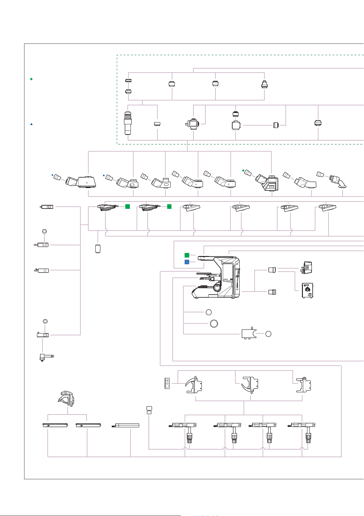
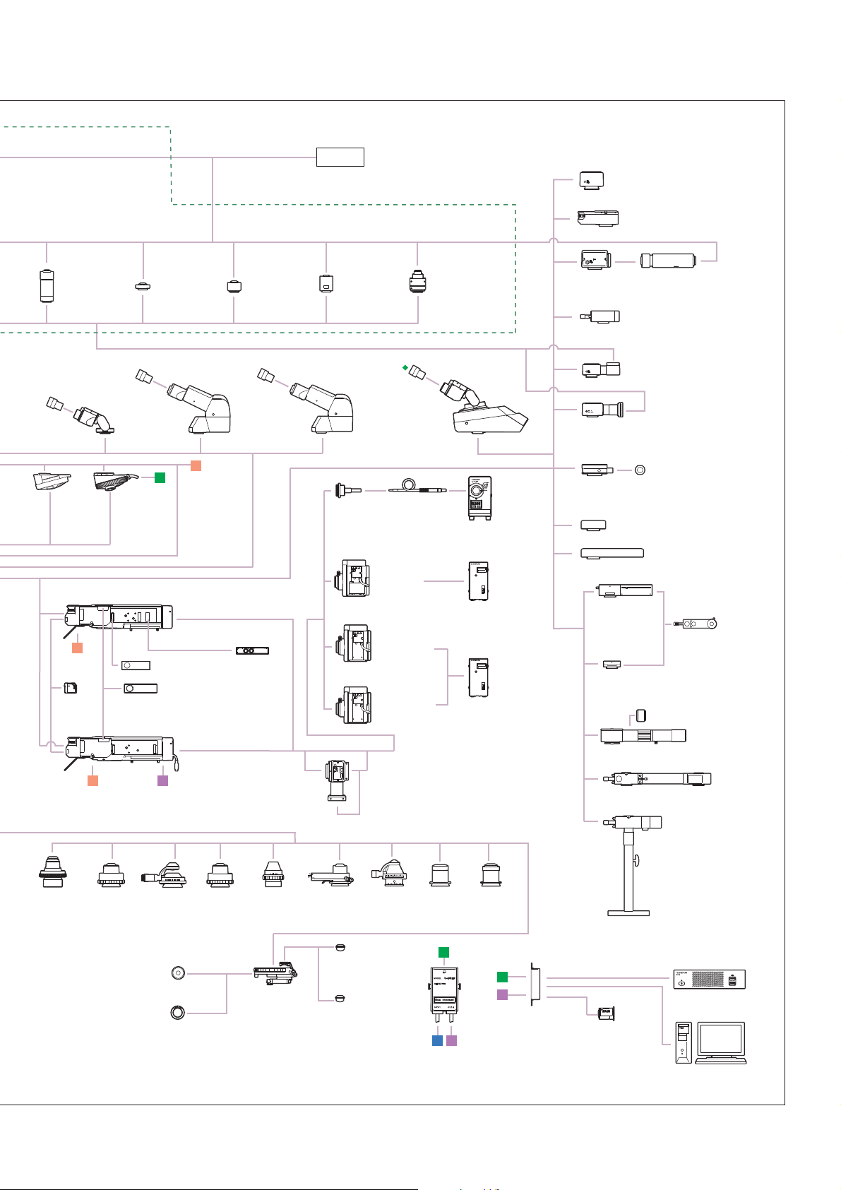
System Diagram
BX53M System Diagram (for Re ected and Combination Re ected/Transmitted Light
Camera adaptors
Digital cameras
U-CMAD3 + U-TV1X-2
U-TV1XC
U-TV0.63XC
U-TV0.5XC-3
U-TV0.35XC-2
U-TV0.25XC
Tubes and eyepieces
Intermediate tubes
Illumination
Reflected
LED light for BF
BX3M-KMA-S
Nosepieces
Coded
reflected
LED light
for BF/DF/POL
BX3M-RLAS-S
Widefield
trinocular tube
U-TR30-2
U-ETR-4
U-TTR-2
×2
Reflected light
for BF/DF
BX3M-RLA-S
LED light
source
BX3M-LEDR
Magnification
changer
U-CA
U-ECA
Halogen
light source
U-LH100L-3 +
TH4-100/200
Option:
U-RMT/TH4-HS
Super widefield
trinocular tube
U-SWTR-3
U-SWETTR-5
Eyepoint
adjuster
U-EPA2
×2
Coded universal
reflected light
BX3M-URAS-S
Mirror units
U-FF
U-FDICR
U-FBF
U-FWBS
U-FDF
U-FWGS
U-FBFL
U-FWUS
LED light
source
BX3M-LEDR
Option:
U-RCV
Objectives and sliders
Halogen light
source
U-LH100L-3
Option:
U-RMT/
TH4-HS
Single tube
U-TLU
Digital cameras
Extension camera adaptor
U-DP + U-DP1XC
Analyzer for
reflected light
U-AN-2
Mercury light source
U-LH100HGAPO +
U-RFL-T
U-LH100HG + U-RFL-T
Option:
U-RCV
Rotatable
analyzer
U-AN360-3
Binocular
tube
U-BI30-2
U-TBI30-3
Trinocular camera adaptor
U-TRU + Camera adaptors
Polarizer slider
for reflected
light
U-PO3
Light guide source
U-LLGAD + U-LLG150
(U-LLG300) + U-HGLGPS
Option:
U-RCV
Polarizer
U-POTP3
Eyepieces
WHN10X
WHN10X-H
CROSS
WHN10X
ND filters
U-25ND50
U-25ND25
U-25ND6
Filters
U-25LBD
U-25LBA
U-25IF550
U-25L42
U-25Y48
U-25FR
U-25
Eyepieces
SWH10X-H
CROSS
SWH10X
Frames
Stages
For BF
U-5RE-2
U-5RES-ESD
Rotatable
stage
U-SRG2
U-SRP
Mechanical
stage
U-FMP
For BF with
slider slot
U-D6RE
U-D6REU-P6RE
U-D7RE
U-D6RES
U-D7RES
U-D6REMC
Plain stage
U-SP
ESD-2
For BF/DF
U-5BDRE
Stage plate
U-MSSP
For BF/DF
with slider slot
U-D5BDRE
U-P5BDRE
U-D6BDRE
U-D5BDREMC
U-
D5BDRES-ESD
U-D6BDRES-S
U-D6BDREMC
Height adaptor
BX3M-ARMAD
BX53M frame for
reflected light
BX53MRF-S
Controller for BX3M
Mechanical right/left
hand control stage
U-SVRM U-SVLM
Option: U-SHG/U-SHGT
Specimen
holders
U-HLD-4
U-HLDT-4
U-HRD-4
U-HRDT-4
Transmitted
LED lamp housing
BX3M-LEDT
Right/left hand control
large-size stage
U-SIC4R2 U-SIC4L2
*
*
*
*
BF
objectives
BF/DF
objectives
BX53M frame for
reflected/transmitted light
BX53MTRF-S
Stage plate
U-MSSP4
BF
objectives
Controller for BX3M
Plate
U-WHP2
Wafer holder plate
BH2-WHR43
DIC sliders
U-DICR
U-DICRH
U-DICRHC
Control box
BX3M-CB
Stage glass
plate
U-MSSPG
MIX slider
U-MIXR
BF/DF
objectives
Hand switch
U-HSEXP
BX3M-HSRE
BX3M-HS
Stage plate
U-SP64
*
DIC sliders
U-DICR
U-DICRH
U-DICRHC
Stand-alone
connection kit
DP2-SAL
Right hand control 150 mm x 100 mm stage
U-SIC64
Option: U-SHG U-SHGT
Wafer holder plate
U-WHP64
Wafer holder plate
BH2-WHR43
BH2-WHR54
BH2-WHR65
BD-M-AD
BF
objectives
PC with OLYMPUS
Stream Software
DIC sliders
U-DICR
U-DICRH
U-DICRHC
Stage glass plate
U-SPG64
*
Condensers
*For transmitted light combination only
Condenser
U-SC3
U-AC2
*
U-POC-2
*
Filter (Ø45)
U-POT
43IF550-W45
*
45-IF546* U-FC
Long working
*
*
*
distance condenser
U-LWCD
*
2-1
Page 6

Control box and cable connection diagram
Coded nosepiece
U-5RES-ESD
U-D5BDRES-ESD
U-D6RES
U-D7RES
U-D6BDRES-S
Frame
BX53MRF-S
BX53MTRF-S
Transmitted LED
lamp housing
BX3M-LEDT
Stand-alone light manager configuration
BX53M frame for
reflected light
BX53MRF-S
Coded Illuminator
BX3M-RLAS-S
BX3M-URAS-S
Reflected LED
lamp housing
BX3M-LEDR
Manual, coded, or motorized nosepiece
(Ergonomic hand switch configuration)
Hand switch
BX3M-HS
Manual nosepiece
U-P4RE
U-5RE-2
U-D6RE
U-D6RE-ESD-2
U-P6RE
OR
Coded nosepiece
U-5RES-ESD
U-D5BDRES-ESD
U-D6RES
OR
Motorized nosepiece
U-D6REMC
U-D5MDREMC
U-D6BDREMC
Cable for
motorized nosepiece
BX3M-RMCBL
Control box
BX3M-CB
U-D7RE
U-5BDRE
U-D5BDRE
U-P5BDRE
U-D6BDRE
U-D7RES
U-D6BDRES-S
Hand switch
for motorized
nosepiece
BX3M-HSRE
MIX slider for
reflected light
observation
U-MIXR
Cable for
U-MIXR
U-MIXRCBL
Hand switch for
exposure
U-HSEXP
Manual or coded IlluminatorReflected light or transmitted light
Manual Illuminator
BX3M-KMA-S
Manual Illuminator
BX3M-RLA-S
PC with OLYMPUS
Stream Software
OR
Stand-alone
connection kit
DP2-SAL
OR
Reflected LED lamp housing
BX3M-LEDR
OROR
BX53M frame for
reflected/transmitted light
BX53MTRF-S
MIX observation configuration
Frame
BX53MRF-S
BX53MTRF-S
PC with OLYMPUS
Stream Software
Transmitted LED
lamp housing
BX3M-LEDT
Control box
BX3M-CB
Hand switch
BX3M-HS
Motorized nosepiece
U-D6REMC
U-D5BDREMC
U-D6BDREMC
Hand switch for
motorized nosepice
BX3M-HSRE
Nosepiece and slider ObjectivesFrame, control box, and hand switch
MIX slider for
reflected light observation
U-MIXR
Cable for
motorized
nosepiece
BX3M-RMCBL
Control box
BX3M-CB
BF/DF with slider slot for
DIC/MIX nosepiece
U-D5BDRE
U-P5BDRE
U-D6BDRE
U-D5BDRES-ESD
U-D6BDRES-S
U-D5BDREMC
U-D6BDREMC
Cable for U-MIXR
U-MIXRCBL
Coded Illuminator
BX3M-RLAS-S
Coded Illuminator
BX3M-URAS-S
OR
Reflected LED lamp housing
BX3M-LEDR
BF/DF objectives
MPLN BD series
MPLFLN BD series
MPLFLN BDP series
LMPLFLN BD series
2-2
Page 7

System Diagram
BXFM System Diagram
Camera adaptors
Digital cameras
U-CMAD3 + U-TV1X-2
U-TV1XC
U-TV0.63XC
U-TV0.5XC-3
U-TV0.35XC-2
U-TV0.25XC
Tubes and eyepieces
Intermediate tubes
Illumination
Reflected
LED light
for BF
BX3M-KMA-S
Coded reflected
LED light
for BF/DF/POL
BX3M-RLAS-S
Widefield
trinocular tube
U-TR30-2
U-ETR-4
U-TTR-2
×2
Reflected light
for BF/DF
BX3M-RLA-S
LED light
source
BX3M-LEDR
Power supply
for LED
BX3M-PSLED
Magnification
changer
U-CA
U-ECA
Halogen light
source
U-LH100L-3 +
TH4-100/200
Option: U-RMT/TH4-HS
LED light
source
BX3M-LEDR
Option:
U-RCV
Super widefield
trinocular tube
U-SWTR-3
U-SWETTR-5
×2 ×2
Coded universal
reflected light
BX3M-URAS-S
Mirror units
U-FF
U-FBF
U-FDF
U-FBFL
Halogen light
source
U-LH100L-3 +
TH4-100/200
Option:
U-RMT/
TH4-HS
U-FDICR
U-FWBS
U-FWGS
U-FWUS
Mercury light
source
U-LH100HGAPO +
U-RFL-T
U-LH100HG +
U-RFL-T
Option:
Single tube
U-TLU
Eyepoint
adjuster
U-EPA2
U-RCV
Light guide
source
U-LLGAD +
U-LLG150
(U-LLG300) +
U-HGLGPS
Option:
U-RCV
Binocular
tube
U-BI30-2
U-TBI30-3
Digital cameras
Extension camera adaptor
U-DP + U-DP1XC
Reflected light
for BF
U-KMAS
LED light
source
BX3M-LEDR
Power supply
for LED
BX3M-PSLED
Halogen light
source
U-LH100L-3 +
TH4-100/200
Option:
U-RMT/TH4-HS
Eyepieces
WHN10X
WHN10X-H
CROSS
WHN10X
Eyepieces
SWH10X-H
CROSS
SWH10X
Trinocular camera adaptor
U-TRU + Camera adaptors
Analyzer for
reflected light
U-AN-2
Polarizer slider
for reflected light
U-PO3
ND filters
U-25ND50
U-25ND25
U-25ND6
Rotatable
analyzer
U-AN360-3
Polarizer
U-POTP3
Filters
U-25IF550
U-25L42
U-25Y48
U-25FR
U-25
Nosepieces
Frame
For BF
U-5RE-2
U-5RES-ESD
Illuminator holder for BX3M
BX3M-ILH
Option: BXFM-ILHSPU
For BF with
slider slot
U-D6RE
U-D6RE-ESD-2
U-P6RE
U-D7RE
U-D6RES
U-D7RES
U-D6REMC
BXFM frame
BXFM-F
Controller for BXFM
For BF/DF
U-5BDRE
Power supply
for LED
BX3M-PSLED
For BF/DF
with slider slot
U-D5BDRE
U-P5BDRE
U-D6BDRE
U-D5BDREMC
U-D5BDRES-ESD
U-D6BDRES-S
U-D6BDREMC
Objectives
and sliders
Controller for BXFM
BF
objectives
BF/DF
objectives
BXFM control box
BX3M-CBFM
lluminator holder BXFM
BXFM-ILHS
U-MIXR
U-DICR
U-DICRH
U-DICRHC
BF
objectives
Hand switch
BX3M-HSRE
BX3M-HS
BF/DF
objectives
Stand-alone
connection kit
DP2-SAL
U-DICR
U-DICRH
U-DICRHC
U-DICR
U-DICRH
U-DICRHC
BD-M-AD
BF
objectives
PC with OLYMPUS
Stream Software
*U-ST is not available with BX3M-ILH.
Stand
U-ST*
SZ-STL
2-3
Control box for
coded function
U-CBS
Hand switch
for exposure
U-HSEXP
Stand-alone
connection kit
DP2-SAL
PC with OLYMPUS
Stream Software
Page 8

Control box and cable connection diagram
Coded nosepiece
U-5RES-ESD
U-5BDRES-ESD
U-D6RES
U-D7RES
U-D6BDRES-S
MIX observation configuration
BXFM control box
BX3M-CBFM
Control box for
coded function
U-CBS
Hand switch
for exposure
U-HSEXP
Hand switch
BX3M-HS
Coded Illuminator
BX3M-RLAS-S
BX3M-URAS-S
PC with OLYMPUS
Stream Software
Stand-alone
connection kit
Note:
DP2-SAL is available only with either the coded system or
the motorized system, but not with both.
DP2-SAL
Nosepiece and slider ObjectivesFrame, control box, and hand switch
BF/DF with slider slot for DIC/MIX
U-D5BDRE
U-P5BDRE
U-D6BDRE
MIX slider for
reflected light observation
U-MIXR
U-D5BDRES-ESD
U-D6BDRES-S
U-D5BDREMC
U-D6BDREMC
Extension cable for
U-MIXR
U-MIXRECBL
Motorized nosepiece
U-D6REMC
U-D5BDREMC
U-D6BDREMC
Extension cable
for motorized
nosepiece
BX3M-RMECBL
BXFM control box
BX3M-CBFM
Hand switch
BX3M-HS
Hand switch
for motorized
nosepiece
BX3M-HSRE
BF/DF objectives
MPLN BD series
MPLFLN BD series
MPLFLN BDP series
LMPLFLN BD series
MIX slider for
reflected light
observation
U-MIXR
Extension cable for
U-MIXR
U-MIXRECBL
Motorized nosepiece configuration
BXFM control box
BX3M-CBFM
Hand switch
for motorized
nosepiece
BX3M-HSRE
Nosepiece and sliderControl box and hand switch
Motorized nosepiece
U-D5BDREMC
U-D6REMC
U-D6BDREMC
Extension cable
for motorized
nosepiece
BX3M-RMECBL
2-4
Page 9

System Diagram
BX63 System Diagram
TR-Adaptor
WHN10X-H,
CROSS WHN10X
Eyepieces
U-CT30-2
Centering telescope
WHN10X,
*
WHN10X-H,
CROSS WHN10X
Eyepieces
U-CT30-2
Centering telescope
U-FMT
F-mount adaptor
U-TMAD
T-mount adaptor
U-TVZ
Zoom
adaptor
U-TV1X-2
TV adaptor
U-SMAD
Sony-mount
adaptor
U-BMAD
Bayonet-mount
adaptor
U-DPCAD
Dual port tube
with C-mounts
U-CMAD3
C-mount adaptor
U-CMDPTS
C-mount adaptor
for U-DPTS
U-DPTS
Multi double port
tube
U-CMDPTS
C-mount adaptor
for U-DPTS
U-TV0.63XB
0.63X
B4-mount
adaptor
U-TV0.25XC
0.25X
C-mount
adaptor
U-GAN
Analyzer for
urate crystals
observation
U-DICT
DIC slider for
transmitted light
1
U-ETR-4*
Erect image
trinocular tube
U-ANT
Analyzer for
transmitted light
U-DICTS
Shift DIC slider for transmitted light
U-DICTHR
High-resolution DIC slider
for transmitted light
U-DICTHC
High-contrast DIC slider
for transmitted light
B
U-IFCBL200
Interface cable,
200 cm
U-POT
Polarizer
U-FC
Filter cassette
U-TR30NIR
Trinocular tube
U-MCZ
Controller
Filter (ø45)
BX3-ARM
Standard arm
U-TR30-2
Trinocular tube
U-D7REA
Motorized 7-position nosepiece
OBJECTIVES
E
BX63F
BX63 frame
F
Touch-screen controller
(attached to BX63F)
U-TTR-2
Tilting trinocular
tube
U-IFCBL50
Interface cable, 50 cm
A
U-LH100ADP
LH100 adaptor
U-BI30-2
Binocular tube
U-AW
Motorized
attenuator wheel
U-LHLEDC
LED lamp
housing
U-D7RES
Coded 7-position
nosepiece
U-IFCBL15
Interface cable, 15 cm
U-IFCBL200
Interface cable, 200 cm
U-LH100-3
100 W halogen
lamp housing
1
U-TBI-3*
Tilting binocular tube
U-D6RES
Coded 6-position
nosepiece
U-RMT
Extension cord
E
AAA
A
B
C
U-HLD-4,
U-HLDT-4
Specimen holder
U-CST
Centering target
U-SHG
U-SHGT
Rubber grips
*1 Slight vignetting may occur in combination with an additional intermediate attachment or uorescence illuminator. *2 Requires an additional intermediate attachment or uorescence illuminator.
*3 Cannot be used with BX3-UCD8A and U-UCD8-2
U-SVLO
Oil rectangular
stage with
left-hand
control
U-SVRO
Oil rectangular
stage with
right-hand
control
BX3-STAD
Stage adaptor
U-HRD-4,
U-HRDT-4
Specimen holder
U-SVLB-4
Mechanical
stage with
left-hand
control
U-HLS-4,
U-HLST-4
Specimen holder
U-SVRB-4
Mechanical
stage with
right-hand
control
D
Control box
(attached to BX3-SSU)
XY-controller
(attached to BX3-SSU)
BX3-SSU
Ultrasonic stage
2-5
Page 10

CAMERAS
U-KPA
Intermediate attachment for
simple polarizing observation
U-ANT
Analyzer for
transmitted light
U-TV0.35XC-2
0.35X
C-mount
adaptor
U-TBI-3-CLI*
Tilting binocular
tube
Mirror units
U-TV0.5XC-3
0.5X
C-mount
adaptor
1
BX3-RFAS
Coded fluorescence illuminator
U-TTBI
Ergonomic
binocular tube
E
U-AN-2
Analyzer slider
BX3M
BX3-RFAA
E
Motorized
fluorescence
illuminator
U-TV0.63XC
0.63X
C-mount
adaptor
A
U-IFCBL15
Interface cable, 15 cm
U-ETBI
Ergonomic
erect image
binocular tube
U-LHEAD
Extension adaptor
for lamp housing
A
U-TV1XC
C-mount
adaptor 1X
(XY adjustment)
U-TTLBI*
Tilting, telescopic,
lifting binocular tube
U-AW
Motorized
attenuator wheel
2
U-DULHA
Double lamp housing
adaptor
U-IFCBL15
Interface cable, 15 cm
U-IFCBL200
Interface cable, 200 cm
B
C
D
F
BX3-CBH
Control box
A
B
C1394A
Interface cable
U-LLGAD
Liquid light
guide
adaptor
U-CA
Magnification changer
U-EPA2
Eyepoint adjuster
U-EPAL-2
Eyepoint adjuster
U-LLG150/
U-LLG300
Liquid light
guide
(1.5 m/3 m)
U-LH75XEAPO
75 W xenon
apo lamp
housing
U-LH100HGAPO
100 W mercury
apo lamp
housing
U-LH100HG
100 W mercury
lamp housing
PC (software)
U-HGLGPS
Light source
U-RFL-T
LIFE TIME
BURNER ON
U-RX-T
Power supply unit
for xenon lamp
U-RFL-T
LIFE TIME
BURNER ON
U-RFL-T
Power supply unit
for mercury lamp
IX2-GCP
Glass stage
insert plate
3
IX-SCL
Slide clip
IX-CP50
Insert plate
IX-SVL2*
Cross stage with short
left handle
U-SC3
Swing-out
condenser
U-AAC
Achromatic/
aplanatic
condenser
U-ULC-2
Ultra-low
condenser
U-DCD
Darkfield
condenser, dry
Optical elements
U-CO1.25X
Low magnification
conversion lens for UCD
2-6
U-DCW
Darkfield
condenser, oil
U-UCD8-2
8-position
universal
condenser
BX3-UCD8A
Motorized
universal
condenser
A
U-TLO
Oil top lens
U-TLD
Dry top lens
U-IFCBL15
Interface cable, 15 cm
Page 11

System Diagram
BX53 System Diagram
TR-Adaptor
WHN10X-H,
CROSS WHN10X
Eyepieces
U-CT30-2
Centering telescope
WHN10X, WHN10X-H,
*
CROSS WHN10X
Eyepieces
U-CT30-2
Centering telescope
SWH10X-H,
CROSS SWH10X,
MICRO SWH10X
Eyepieces
U-CT30-2
Centering telescope
U-GAN
Analyzer for urate crystals
observation
U-ANT
Analyzer for
transmitted light
U-DICT
DIC slider for
transmitted light
U-DICTS
Shift DIC slider for
transmitted light
U-DICTHR
High-resolution DIC
slider for transmitted light
U-DICTHC
High-contrast DIC slider
for transmitted light
U-ANT
Analyzer for
transmitted light
U-TAD
Plate adaptor
COMPENSATORS
U-SWETTR-5
Super widefield
erect image
tilting trinocular
observation tube
U-SWTR-3
Super widefield
trinocular tube
OBJECTIVES
U-FMT
F-mount adaptor
U-TMAD
T-mount adaptor
U-TVZ
Zoom
adaptor
U-ETR-4*
Erect image
trinocular tube
*
U-D7REA
Motorized
7-position
nosepiece
U-TV1X-2
TV adaptor
A
1
U-POT
Polarizer
U-FC
Filter cassette
U-SMAD
Sony-mount
adaptor
U-TR30NIR
Trinocular tube
*
U-D7RES
Coded 7-position
nosepiece
BX3-ARM
Standard arm
BX53F
BX53 frame
U-BMAD
Bayonet-mount
adaptor
U-DPCAD
Dual port tube
with C mounts
U-TR30-2
Trinocular tube
*
B B
U-LH100-3
100 W halogen
lamp housing
Filter (ø45)
U-D6RES
Coded 6-position
nosepiece
U-CMAD3
C-mount adaptor
U-CMDPTS
C-mount adaptor
for U-DPTS
U-DPTS
Multi double port
tube
U-TTR-2
Tilting trinocular tube
Mirror units
C
C
U-CMDPTS
C-mount adaptor
for U-DPTS
U-BI30-2
Binocular tube
U-D7RE
Septuple revolving
nosepiece for
DIC/simple POL
ACC
B
U-TBI-3*
Tilting binocular tube
*
BX3-RFAA*
Motorized fluorescence
illuminator
U-AN-2
Analyzer slider
BX3-RFAS*
Coded fluorescence
illuminator
U-AN-2
Analyzer slider
BX3-URA
Universal reflected illuminator
U-AN-2
Analyzer slider
*
U-D6RE
Sextuple revolving
nosepiece for
DIC/simple POL
4
4
U-TV0.63XB
0.63X
B4-mount
adaptor
1
BX3-25ND6
ND filter
BX3-25ND25
ND filter
U-CST
Centering
U-SP
Plain
stage
target
U-SHG
Rubber grip
U-SHGT
Rubber grip
U-SVRO
Oil rectangular
stage with
right-hand
control
U-FMP
Mechanical
stage
U-SRG2
Rotatable
graduated
stage
*1 Slight vignetting may occur in combination with an additional intermediate attachment or observation method. *2 Requires an additional intermediate attachment or uorescence illuminator.
*3 Cannot be used with U-TTLBI. *4 Compatible with FN 22. *5 Cannot be used with BX3-URA. *6 Stand is standard equipment with the U-MDOSV and U-MDO10R3. *7 An auxiliary lens is
equipped.
U-SRP
Precision
rotatable
stage
U-HLD-4,
U-HLDT-4
Specimen
holder
U-SVLO
Oil rectangular
stage with
left-hand
control
U-HRD-4,
U-HRDT-4
Specimen
holder
U-SVRB-4
Mechanical
stages with
right-hand
control
U-SVLB-4
Mechanical
stages with
left-hand
control
U-HLS-4,
U-HLST-4
Specimen
holder
2-7
Page 12

U-TV0.25XC
0.25X
C-mount
adaptor
U-TBI-3-CLI*
Tilting binocular tube
1
*
U-P6RE
Centerable sextuple
revolving nosepiece
U-LHEAD*
Extension
adaptor for
lamp housing
5
U-TV0.35XC-2
0.35X
C-mount
adaptor
*
U-TTBI
Ergonomic
binocular tube
U-DULHA
Double
lamp house
adaptor
U-AW
Motorized
attenuator wheel
U-P4RE
Centerable
revolving
nosepiece
A
U-TV0.5XC-3
0.5X
C-mount
adaptor
*
U-ETBI
Ergonomic erect
image binocular
tube
U-5RE-2
Quintuple
revolving
nosepiece
U-LLGAD
Liquid light
guide
adaptor
CAMERAS
U-TV0.63XC
0.63X
C-mount
adaptor
U-TTLBI*
Tilting,
telescopic,
lifting binocular
tube
C
U-LLG150/
U-LLG300
Liquid light
guide
(1.5 m/3 m)
U-LH75XEAPO
75 W xenon
apo lamp
housing
U-LH100HGAPO
100 W mercury
apo lamp
housing
U-LH100HG
100 W mercury
lamp housing
U-TV1XC
C-mount
adaptor 1X
(XY adjustment)
2
U-HGLGPS
Light source
LIFE TIME
BURNER ON
U-RX-T
Power supply unit
for xenon lamp
LIFE TIME
BURNER ON
U-RFL-T
Power supply unit
for mercury lamp
U-ECA
Magnification changer 2X
U-KPA
Intermediate attachment for
simple polarizing observation
U-CA
Magnification changer
1*3
U-DP*
Dual port
U-OPA
Intermediate attachment for
orthoscopic observation
U-DP1XC
Dual port 1X
U-APT
Arrow pointer
U-EPA2
Eyepoint adjuster
U-EPAL-2
Eyepoint adjuster
1*3
U-TRU*
Trinocular intermediate unit
U-TRUS*
Trinocular intermediate unit
U-CPA
Intermediate attachment for
conoscopic and orthoscopic
observation
U-DAL10X
Drawing attachment (10X)
U-DA
Drawing attachment
U-SDO3
Side-by-side observation
attachment
U-MDOB3
Multi-observation
body
U-MDO10B3
Multi-observation body
for 10 persons
U-ANT
Analyzer for
transmitted light
1
U-AN360P-2
Rotatable analyzer
U-DO3
Dual observation attachment
U-MDOSV*
Multi-observation
side viewer
6
7
U-LC*
Lowmagnification
condenser
U-AC2
Abbe
condenser
Optical devices
U-CO1.25X
Low-magnification
conversion
lens for UCD
U-SC3
Swing-out
condenser
BX3-UCD8A
Motorized universal
condenser
U-UCD8-2
8-position
universal condenser
U-AAC
Achromatic/
aplanatic
condenser
U-ULC-2
Ultra-low
condenser
A
U-PCD2
Phase/darkfield
condenser
U-TLO
Oil top lens
U-TLD
Dry top lens
U-DCD
Darkfield
condenser,
dry
U-POC-2
Polarizing
condenser
U-DCW
Darkfield
condenser,
oil
B
A
2-8
U-CBS
Control box for
coded function
U-IFCBL200
Interface cable,
200 cm
U-MDO10R3*
Multi-observation body for 10 persons
6
U-HSEXP
Hand switch for
exposure
U-HSCBM
Hand switch for CBM
U-CBM
Control box
PC (Software)
6
Stand*
DP2-SAL
Stand-alone Connection Kit
Page 13
System Diagram
BX43 System Diagram
TR-Adaptor
WHN10X-H,
CROSS WHN10X
Eyepieces
U-CT30-2
Centering telescope
WHN10X, WHN10X-H,
*
CROSS WHN10X
Eyepieces
U-CT30-2
Centering telescope
SWH10X-H,
CROSS SWH10X,
MICRO SWH10X
Eyepieces
U-CT30-2
Centering telescope
U-SWETTR-5
Super widefield
erect image
tilting trinocular
observation tube
U-GAN
Analyzer for urate
crystals observation
U-ANT
Analyzer for
transmitted light
U-DICT
DIC slider for
transmitted light
U-DICTS
Shift DIC slider for
transmitted light
U-DICTHR
High-resolution DIC
slider for transmitted light
U-DICTHC
High-contrast DIC slider
for transmitted light
U-ANT
Analyzer for
transmitted light
U-TAD
Plate adaptor
U-SWTR-3
Super widefield
trinocular tube
OBJECTIVES
A
U-D7RES
Coded
7-position
nosepiece
U-FMT
F-mount
adaptor
U-TMAD
T-mount
adaptor
U-TVZ
Zoom
adaptor
U-ETR-4*
Erect image
trinocular tube
*
U-TV1X-2
TV
adaptor
1
A
U-D6RES
Coded
6-position
nosepiece
U-SMAD
Sony-mount
adaptor
U-TR30NIR
Trinocular tube
*
A
B
U-BMAD
Bayonet-mount
adaptor
U-DPCAD
Dual port tube
with C-mounts
U-TR30-2
Trinocular tube
*
U-D7RE
Septuple revolving
nosepiece for
DIC/simple POL
45LBDIF
U-POT
Polarizer
U-CMDPTS
C-mount adaptor
for U-DPTS
U-DPTS
Multi double
port tube
U-TTR-2
Tilting trinocular tube
U-D6RE
Sextuple revolving
nosepiece for
DIC/simple POL
BX43F
BX43 frame
U-FC
Filter cassette
U-CMAD3
C-mount
adaptor
U-CMDPTS
C-mount adaptor
for U-DPTS
U-BI30-2
Binocular tube
*
U-LS30ADP
LS30 adaptor
U-LHLEDC
LED lamp housing
Filter (ø45)
U-P6RE
Centerable
revolving
nosepiece
U-TV0.63XB
B4-mount
adaptor
1
U-TBI-3*
Tilting binocular tube
*
U-P4RE
Centerable
revolving
nosepiece
U-LS30-5
Lamp socket for
30 W halogen
TL4
Power supply
unit
COMPENSATORS
U-CST
Centering target
U-FMP
Mechanical
stage
U-SRG2
Rotatable
graduated
stage
*1 Slight vignetting may occur in combination with an additional intermediate attachment or observation method. *2 Requires an additional intermediate attachment or uorescence illuminator.
*3 Cannot be used with U-TTLBI. *4 Compatible with FN 22. *5 An auxiliary lens is equipped.
U-SRP
Precision
rotatable
stage
U-SP
Plain
stage
U-SHG
Rubber grip
U-SHGT
Rubber grip
U-SVRO
Oil rectangular
stage with
right-hand
control
U-HLD-4,
U-HLDT-4
Specimen
holder
U-SVLO
Oil rectangular
stage with
left-hand
control
U-SVRB-4
Mechanical
stages with
right-hand
control
U-HRD-4,
U-HRDT-4
Specimen
holder
U-SVLB-4
Mechanical
stages with
left-hand
control
U-HLS-4,
U-HLST-4
Specimen
holder
2-9
Page 14
CAMERAS
U-ECA
Magnification changer 2x
U-CA
Magnification changer
U-TV0.25XC
0.25X
C-mount
adaptor
U-TBI-3-CLI*
Tilting binocular tube
1
*
U-5RE-2
Quintuple
revolving
nosepiece
C
Mirror units
*
U-TTBI
Ergonomic
binocular tube
BX43-5RES
Coded
5-position
nosepiece
for BX43
U-TV0.35XC-2
0.35X
C-mount
adaptor
C
A
BX3-URA
Universal reflected illuminator
U-PO
Polarizer
U-AN-2
Analyzer slider
U-TV0.5XC-3
0.5X
C-mount
adaptor
*
U-ETBI
Ergonomic erect
image binocular
tube
BX3-6ND6
ND filter
BX3-25ND25
ND filter
U-TV0.63XC-3
0.63X
C-mount
adaptor
U-LLGAD
Liquid light
guide
adaptor
U-LH75XEAPO
75 W xenon
apo lamp
housing
U-LH100HGAPO
100 W mercury
apo lamp
housing
U-LH100HG
100 W mercury
lamp housing
U-TV1XC
C-mount
adaptor 1X
(XY adjustment)
2
U-TTLBI*
Tilting,
telescopic,
lifting binocular tube
U-LLG150/
U-LLG300
Liquid light
guide
(1.5 m/3 m)
U-HGLGPS
Light source
U-RFL-T
LIFE TIME
BURNER ON
U-RX-T
Power supply unit
for xenon lamp
U-RFL-T
LIFE TIME
BURNER ON
U-RFL-T
Power supply unit
for mercury lamp
1*3
U-DP*
Dual port
U-TRUS*
Trinocular intermediate unit
U-KPA
Intermediate attachment for
simple polarizing observation
U-CPA
Intermediate
attachment for
conoscopic and
orthoscopic
observation
U-OPA
Intermediate attachment for
orthoscopic observation
U-DP1XC
Dual port 1x
U-APT
Arrow pointer
1*3
U-TRU*
Trinocular intermediate unit
3
U-ANT
Analyzer for
transmitted light
U-EPA2
Eyepoint adjuster
U-EPAL-2
Eyepoint adjuster
U-AN360P-2
Rotatable
analyzer
U-DAL10X
Drawing attachment 10x
5
U-LC*
Low
magnification
condenser
C
U-AC2
Abbe
condenser
BX3-RFAS*
Coded
fluorescence
D
illuminator
U-SC3
Swing-out
condenser
U-AAC
Achromatic/
Aplanatic
condenser
Optical devices
U-CO1.25X
Low magnification
conversion
lens for UCD
4
U-DULHA
Double
lamp house
adaptor
U-ULC-2
Ultra-low
condenser
U-UCD8-2
8-position
universal
condenser
U-PCD2
Phase/darkfield
condenser
U-TLO
Oil top lens
U-TLD
Dry top lens
U-POC-2
Polarizing
condenser
U-DCD
Darkfield
condenser,
dry
B
U-IFRES
Interface for
coded nosepiece
2-10
U-DA
Drawing attachment
U-DO3
Dual observation attachment
U-SDO3
Side-by-side observation
attachment
U-DCW
Darkfield
condenser,
oil
U-RX-T
A
Power supply unit
for xenon lamp
A
D
U-CBS
Control box for
D
coded function
U-HSEXP
Hand switch for
exposure
DP2-SAL
Stand-alone connection kit
PC (Software)
Page 15

System Diagram
BX3 Series Basic Motorized System Diagram
Full Motorized System Basic Conguration for BX3 series
BX3-RFAA
BX3-RFAS
Motorized fluorescence
illuminator
U-D7REA
U-D7RES
U-D6RES
Motorized 7-position
nosepiece
U-IFCBL50
Interface cable, 50 cm
U-IFCBL200
Interface cable,
200 cm
U-MCZ
Controller
Semi-Motorized System Basic Conguration for BX3 series
BX3-RFAA
Motorized fluorescence
illuminator
BX63F
BX63 frame
Touch-panel controller
(attached to BX63F)
U-IFCBL15
Interface cable, 15 cm
BX3-CBH
Control box
BX3-UCD8A
Motorized universal condenser
C1394A
Interface cable
PC (software)
U-D7REA
Motorized 7-position
nosepiece
U-IFCBL50
Interface cable, 50 cm
Coded System Basic Congratulation for BX3 series
BX3-RFAS
Coded fluorescence
illuminator
U-D7RES
Coded 7-position
nosepiece
BX43F
BX43 frame
BX53F
BX53 frame
BX43F
BX43 frame
BX53F
BX53 frame
U-IFCBL15
Interface cable, 15 cm
U-IFCBL200
Interface cable,
200 cm
U-CBS
Control box for
coded function
BX3-UCD8A
Motorized universal condenser
U-HSCBM
Hand switch for CBM
U-CBM
Control box
PC (software)
PC (software)
*Please refer to "Section 13 Motorized Unit" for each motorized unit in the detail.
**Please consult your nearest Olympus representative for details about motorized system con gurations and combinations.
2-11
Page 16

BX2 Series BXFM System Diagram
Video System
efer to pages 12-1 – 12-2)
(r
U-TV0.25XC U-TV0.35XC-2 U-TV0.5XC-3 U-TV0.63XC U-TV1XC
Observation/Single Tubes and Eyepieces
(refer to pages 8-1 – 8-4)
Video camera
C-mount
U-CMAD3
Video camera
B-mount 2/3"
Video camera
S-mount 2/3"
U-BMAD U-SMAD
SN
SN
3 G 0 0 7 0 7
3 G 0 0 7 0 7
TOKYO, JAPAN
TOKYO, JAPAN
Video camera
F-mount
U-FMT
U-TMAD
U-TV1X-2
WHN
Eyepieces
Illumination Systems and Power Supply
(refer to pages 5-1 – 6/6)
U-AN360-3
U-AN360IR
FS
AS
ND
BX-RLA2
U-AN
5
6
5
6
SHUTTER
SHUTTER
Focusing Units
efer to pages
(r
4-8 – 4-11)
BXFM-ILH
Wideeld trinocular
observation tubes
U-PO3
U-POIR
AS
FS
BX-URA2
U-POTP3
BXFM-ILHS
SWH
eyepieces
U-RCV
U-25ND6, U-25ND25,
U-25LBD, U-25IF550,
U-25L42, U-25FR,
U-BP1100IR, U-BP1200IR
U-KMAS
Super wideeld trinocular
observation tubes
U-DULHA
U-LH100-3
U-LH100L-3
U-LH100IR
U-LGAD
U-TLU
U-TLUIR
Revolving nosepiece
(refer to pages 11-1 – 11-3)
LG-SF
LG-PS2
TH4-100 TH4-HS
Stands
(refer to page 4-11)
*Different types may be offered in each area.
BXFM-ILHSPU
BXFM-F
U-LH100HGAPO
U-LH100HG
U-LH75XEAPO
U-STSZ-STL
SZ2-STU2
U-RFL-T
U-RX-T
2-12
Page 17

System Diagram
BX2 Series Motorized Unit System Diagram
Observation tubes
U-AN
U-AN360-3
U-PO3
U-POTP3
U-25ND6
U-25ND25
U-25LBD
U-25IF550
U-25L42
U-25FR
Intermediate tubes
(refer to pages 9-1 – 9-3)
Mirror Units
(refer to pages 8-1 – 8-4)
BX-RFAA
MX-AFDIC
U-AFA2M-VIS
BX-RLAA
U-AN
U-FWR
U-ZPCB
Z-Board
(refer to pages 11-1 – 11-8)
(refer to pages 6-1 – 6-6)
U-LH100HGAPO
U-LH100HG
U-LH75XEAPO
U-LH100-3
U-LH100L-3
U-RFL-T
U-RX-T
TH4-100
TH4-HS
U-DICR
U-DICRH
U-DICRHC
*BX-REMCB is also available for BX-RLAA + motorized revolving nosepiece control (refer to page 13-3).
**These illuminators can only attach to the MX51 or BX61 frames.
U-D6REMC
U-D5BDREMC
U-D6BDREMC
BD-M-AD
BXFM-A System Diagram
Video system
(refer to pages 12-1 – 12-2)
Observation tubes
(refer to pages 8-1 – 8-4)
MX-AFDIC U-AN
U-AFA2M-VIS
(refer to pages 3-1 – 3-36)(refer to page 11-2)
BF Objectives
BF/DF Objectives
ø32 Filter
Auxiliary lens
(provided with the BXFMA-F)
U-LGAD
LG-SF
BX-UCB*
See manual
U-LH100HG
U-LH75XEAPO
U-HSTR2
PC
OLYMPUS Stream
Control Software
(refer to page 13-1 – 13-8)
(refer to page 6-3)
U-RFL-T
U-RX-T
(refer to page 6-5)
LG-PS2
BXFMA-F
U-D6REMC
U-P5REMC
U-D5BDREMC
U-D6BDREMC
U-P6BDREMC
Objectives
U-FWR
U-LH100-3
U-LH100L-3
U-IFFH
U-FH
2-13
(refer to page 6-4)
U-RMT
U-ZPCB
Z-Board
BX-UCB
See manual
U-HSTR2
PC
OLYMPUS Stream
Control Software
Page 18

Objectives (for Industrial Applications)
■ De nition for Objective Abbreviations
M PL(Plan) F L N 1 0 0 B D-
M: Metallurgical (no cover)
LM: Long Working Distance
Metallurgical Use
SLM: Super Long Working
Distance Metallurgical Use
LC: Observation Through
Substrate
PL: Plan:
Corrects Field
Curvature on
the Periphery of
the Image Plane
None: Achromat:
Corrects Chromatic Aberration at 2 Wavelengths of Blue
and Red
FL: Semi Apochromat:
Corrects Chromatic Aberration in the Visible Range
(violet to red)
APO: Apochromat:
Optimally Corrects Chromatic Aberration in the Entire
Visible Band (violet to red)
Number:
Objective
Magni cation
None: Bright eld
BD: Bright eld/Dark eld
BDP: Bright eld/Dark eld/
IR: Infrared
LCD: Obervation Through
■ Objective Notation
Magni cation Objectives Series Abbreviation (PL: Plan)
In nity-Corrected Optical System
Cover Glass Thickness (no cover)
NA (Numerical Aperture)
For Bright eld Observation
FN (Field Number)
■ Objective Series List
MPLAPON 50/100
MPLAPON O 100
MPLFLN
LMPLFLN 5/10/20/50/100
MPLN 5/10/20/50/100
LCPLFLN-LCD 20/50/100
SLMPLN 20/50/100
LMPLN-IR 5/10 22 For near-IR observation
LCPLN-IR 20/50/100
MPLFLN-BD 5/10/20/50/100/150
MPLFLN-BDP 5/10/20/50/100
LMPLFLN-BD 5/10/20/50/100
MPLN-BD 5/10/20/50/100
WLI100XMRTC 100X 22 Mirau objective
* DIC Prism U-DICR: UM/LM Position, U-DICRHC: LM Position Fixed, U-DICRH: UM Position Fixed. *
: Responds; : Optimally Responds; BF: Bright eld; DF: Dark eld; DIC: Differential Interference Contrast; POL: Polarized light; FL: Fluorescence
Series Magni cation BF DF DIC* POL FL FN Remarks
1.25/2.5
5/10/20/40*/50/100
U
U *
L
L
U *
U *
L
26.5
26.5
1.25X: 22/2.5X: 26.5 We recommend using a polarizer and analyzer
26.5
26.5
22
26.5 For LCD
26.5
22 For near-IR observation
26.5
26.5
26.5
22
2
40X: BF Only *3 5–20X: U Excitation Also Possible.
■ Features of Each Objective Series
MPLAPON series: M Plan Apochromat — p. 3-2
This series of Plan Apochromat objectives corrects chromatic aberrations at optimal levels.
Olympus guarantees* the optical performance (correction for wavefront aberration) with a
Strehl ratio** of 95% or better. These objectives can be used with Olympus’ U-AFA2M active
auto focus unit.
MPLAPON100XO: M Plan Apochromat — p. 3-2
This Plan Apochromat objective is designed for oil immersion*** and features a numerical
aperture of 1.4. The objective provides excellent chromatic aberration correction and high
resolving power.
MPLFLN series: M Plan Semi Apochromat — p. 3-3
This series of Plan Semi Apochromat objectives delivers high-level correction for chromatic
aberration. The eight objectives in this series offer magni cations ranging from 1.25X to 100X
and a minimum working distance of 1 mm (except 40X). Since the exit pupil position of the
5X–100X objectives is standardized, the position of the DIC prism does not have to be
switched when changing the magni cation (40X is not applicable to DIC observation). For very
low magni cations (1.25X, 2.5X), use the objectives with an analyzer, polarizer, and re ected
light illuminator.
LMPLFLN series: Long Working Distance M Plan Semi Apochromat — p. 3-4
This series of long working distance Plan Semi Apochromat objectives delivers high-level
correction for chromatic aberration. Because of the long working distance, these objectives
are suitable for observing larger samples. Since the exit pupil position of the 5X–100X
objectives is standardized, the position of the DIC prism does not have to be switched when
changing the magni cation.
MPLN series: M Plan Achromat — p. 3-5
Plan Achromat objectives provide excellent image atness up to FN 22.
LCPLFLN-LCD series: LCD Long Working Distance M Plan Semi Apochromat
— p. 3-6
These objectives are designed for making observations through LCD panels and other
samples that have a glass substrate. The correction collar provides aberration correction that
can be matched to the thickness of the glass.
SLMPLN series: Super Long Working Distance M Plan Achromat — p. 3-7
These are high-magni cation Plan Achromat objectives with a super long working distance.
Three magni cations, 20X, 50X, and 100X, are available. For 5X or 10X objectives, select
from the LMPLFLN series.
LMPLN-IR series: IR Long Working Distance M Plan Achromat — p. 3-8
This series is designed for near-infrared microscopy, which is typically used to view the
internal structure of silicon wafers.
LCPLN-IR series: IR Long Working Distance M Plan Achromat — p. 3-9
This series is designed for near-infrared microscopy, which is typically used to view the
internal structure of silicon wafers. These objectives have a correction collar to correct for
aberrations based on the thickness of the silicon or glass substrate.
MPLFLN-BD series: M Plan Semi Apochromat BD — p. 3-10
This series of Plan Semi Apochromat objectives provides high-level correction for chromatic
aberration with a minimum working distance of 1 mm. Since the exit pupil position of the
5X–150X objectives is standardized, the position of the DIC prism does not have to be
switched when changing the magni cation.
MPLFLN-BDP series: M Plan Semi Apochromat BDP — p. 3-11
This series of Plan Semi Apochromat objectives provides high-level correction for chromatic
aberrations with a minimum working distance of 1 mm. Since the exit pupil position of the
5X–100X objectives is standardized, the position of the DIC prism does not have to be
switched when changing the magni cation. This series is optimized for bright eld, dark eld,
and polarized light observations and can be used with differential interference contrast.
LMPLFLN-BD series: Long Working Distance M Plan Semi Apochromat BD — p. 3-12
This series of long working distance Plan Semi Apochromat objectives provides high-level
correction for chromatic aberration and are suitable for observing samples with height or
varying topography. Since the exit pupil position of the 5X–100X objectives is standardized,
the position of the DIC prism does not have to be switched when changing the magni cation.
MPLN-BD series: M Plan Achromat BD — p. 3-13
This series of Plan Achromat objectives provides excellent image atness up to FN 22.
WLI100XMRTC series: White Light Interferometry Objective — p. 3-14
This objective is designed to be used with Mirau-style white light interferometers and tolerates
high temperatures. The objective has a working distance of 0.7 mm and an optimized NA of
0.8 that provides improved light gathering.
* Measurement guarantee assessed with an Olympus interferometer for transmitted
wavefront measurement under the following conditions: a temperature of 23 °C + 1 °C;
measurements made within the 97% range of the pupil diameter.
** Strehl ratio: Indicates in percent (%) the ratio of the proportion of light that an actual optical
system can concentrate with respect to the proportion of light concentrated in the image
plane (central intensity) by an ideal, aberration-free optical system, with the latter serving
as 100%. A higher percentage indicates a higher quality optical system.
*** Speci ed oil: IMMOIL-F30CC
3-1
Polarizing
LCD Panels
Page 19

Objectives
M Plan Apochromat
MPLAPON series
This series of Plan Apochromat objectives corrects chromatic aberrations at optimal levels. Olympus guarantees* the optical performance
(correction for wavefront aberration) with a Strehl ratio** of 95% or better. These objectives can be used with Olympus’ U-AFA2M active
auto focus unit.
MPLAPON50X
ø20.32
4.545
MPLAPON100X
ø20.32
4.5
* Measurement guarantee assessed with an Olympus
interferometer for transmitted wavefront
measurement under the following conditions: a
temperature of 23 °C + 1 °C; measurements made
within the 97% range of the pupil diameter.
** Strehl ratio: Indicates in percent (%) the ratio of the
proportion of light that an actual optical system can
(44.65)
41.62
41
37.98
45
(44.65)
42.78
42.4
38.43
concentrate with respect to the proportion of light
concentrated in the image plane (central intensity)
by an ideal, aberration-free optical system, with the
latter serving as 100%. A higher percentage
indicates a higher quality optical system.
Super Wide eld Eyepiece
SWH10X FN 26.5
Depth of
Focus (μm)
Total
Magni cation
Practical Field
of View (mm)
Depth of
Focus (μm)
W.D.=0.35
Objective
(magni cation)
ø8.8
ø18.9
ø20.3
ø28.5
UIS2 Objectives
NA
W.D.
(mm)
Focal Distance
f (mm)
ø5.5
ø16
W.D.=0.35
ø20.2
ø28
Wide eld Eyepiece
WHN10X FN 22
Total
Weight
(g)
Magni cation
Practical Field
of View (mm)
MPLAPON50X 0.95 0.35 3.6 139 500 0.44 1 500 0.53 1
MPLAPON100X 0.95 0.35 1.8 125 1000 0.22 0.67 1000 0.27 0.7
Screw: W 20.32 mm × 0.706 mm (0.8 in. × 1/36 in.)
M Plan Apochromat
MPLAPON100XO
Unit: mm
This Plan Apochromat objective is designed for oil immersion*** and features a numerical aperture of 1.4. The objective provides
excellent chromatic aberration correction and high resolving power.
MPLAPON100XO
ø20.32
4.5
43.496
36.909
41.676
Weight
(g)
ø6.6
ø17.5
ø22
ø30
Wide eld Eyepiece
Total
Magni cation
WHN10X FN 22
Practical Field
of View (mm)
*** Speci ed Oil: IMMOIL-F30CC
Super Wide eld Eyepiece
SWH10X FN 26.5
Depth of
Focus (μm)
Total
Magni cation
Practical Field
of View (mm)
Unit: mm
Depth of
Focus (μm)
45
(44.9)
W.D.= 0.1
UIS2 Objectives
Objective
(magni cation)
NA
W.D.
(mm)
Focal Distance
f (mm)
MPLAPON100XO 1.4 0.1 1.8 158 1000 0.22 0.59 1000 0.27 0.59
Screw: W 20.32 mm × 0.706 mm (0.8 in. × 1/36 in.)
3-2
Page 20

Objectives
M Plan Semi Apochromat
MPLFLN series
This series of Plan Semi Apochromat objectives delivers high-level correction for chromatic aberration. The eight objectives in this series
offer magni cations ranging from 1.25X to 100X and a minimum working distance of 1 mm (except 40X). Since the exit pupil position
of the 5X–100X objectives is standardized, the position of the DIC prism does not have to be switched when changing the magni cation
(40X is not applicable to DIC observation). For very low magni cations (1.25X, 2.5X), use the objectives with an analyzer, polarizer, and
re ected light illuminator.
MPLFLN1.25X MPLFLN2.5X MPLFLN5X MPLFLN10X
ø28
ø20.32
ø28
ø20.32
ø20.32
ø20.32
4.9
45
41.2
(41.5)
W.D.=3.5
ø28.6
ø29
ø30
45 4.9
31.6
(34.3)
W.D.=10.7
ø24.5
ø29
ø30
45 4.5
(25)
22.55
W.D.=20
ø20.9
ø26
4.545
28.41
(34)
W.D.=11
MPLFLN20X MPLFLN40X MPLFLN50X MPLFLN100X
ø20.32
4.5
35.1
(41.9)
45
4.545
40.5
41.4
(44.37)
35.6
ø20.32
ø20.32
4.845
(44)
41.78
40.8
36.8
45 4.8
(44)
42.61
42.4
38.4
ø14.5
ø26
ø20.32
W.D.=3.1
Objective
(magni cation)
ø12.1
ø26
UIS2 Objectives
NA
W.D.
(mm)
W.D.=0.63
Focal Distance
f (mm)
ø8.5
ø14.4
ø16
ø25.8
Weight
(g)
W.D.=1
Wide eld Eyepiece
Total
Magni cation
ø10.7
ø15.2
ø17.8
ø26
WHN10X FN 22
Practical Field
of View (mm)
Depth of
Focus (μm)
W.D.=1
Super Wide eld Eyepiece
SWH10X FN 26.5
Total
Magni cation
Practical Field
of View (mm)
ø7.8
ø15.2
ø17.8
ø26
Depth of
Focus (μm)
MPLFLN1.25X 0.04 3.5 145 122 12.5 17.6 870 — — —
MPLFLN2.5X 0.08 10.7 72 106 25 8.8 220 25 10.6 220
MPLFLN5X 0.15 20 36 51.5 50 4.4 59 50 5.3 59
MPLFLN10X 0.3 11 18 68.1 100 2.2 15 100 2.7 15
MPLFLN20X 0.45 3.1 9 70.4 200 1.1 5.2 200 1.3 5.1
MPLFLN40X 0.75 0.63 4.5 120 400 0.55 1.66 400 0.66 1.66
MPLFLN50X 0.8 1 3.6 89.9 500 0.44 1.3 500 0.53 1.3
MPLFLN100X 0.9 1 1.8 90.9 1000 0.22 0.73 1000 0.27 0.73
Screw: W 20.32 mm × 0.706 mm (0.8 in. × 1/36 in.)
3-3
Unit: mm
Page 21

Objectives
Long Working Distance M Plan Semi Apochromat
LMPLFLN series
This series of long working distance Plan Semi Apochromat objectives delivers high-level correction for chromatic aberration. Because
of the long working distance, these objectives are suitable for observing larger samples. Since the exit pupil position of the 5X–100X
objectives is standardized, the position of the DIC prism does not have to be switched when changing the magni cation.
LMPLFLN5X LMPLFLN10X LMPLFLN20X
4.9
45
22.2
(22.5)
W.D.=22.5
ø20.32
4.5
(24)
45
ø25.4
ø26
W.D.=21
ø20.32
22.1
ø15.2
ø22.4
LMPLFLN50X LMPLFLN100X
ø20.32
4.9
4.7
ø20.32
ø26
4.8
45
29.31
(33)
W.D.=12
ø20.32
ø17
ø26
30.4
45
Objective
(magni cation)
(34.4)
W.D.=10.6
ø18.2
ø26
UIS2 Objectives
NA
W.D.
(mm)
Focal Distance
f (mm)
45
41.1
(41.6)
W.D.=3.4
37.26
Weight
(g)
ø12.5
ø15
ø18.1
ø26
Total
Magni cation
Wide eld Eyepiece
WHN10X FN 22
Practical Field
of View (mm)
Focus (μm)
Depth of
Super Wide eld Eyepiece
SWH10X FN 26.5
Total
Magni cation
Practical Field
of View (mm)
Depth of
Focus (μm)
LMPLFLN5X 0.13 22.5 36 50 50 4.4 70 50 5.3 70
LMPLFLN10X 0.25 21 18 54 100 2.2 18 100 2.7 18
LMPLFLN20X 0.4 12 9 73 200 1.1 6.1 200 1.3 6.1
LMPLFLN50X 0.5 10.6 3.6 77 500 0.44 2.5 500 0.53 2.5
LMPLFLN100X 0.8 3.4 1.8 94 1000 0.22 0.87 1000 0.27 0.87
Screw: W 20.32 mm × 0.706 mm (0.8 in. × 1/36 in.)
Unit: mm
3-4
Page 22

Objectives
M Plan Achromat
MPLN series
Plan Achromat objectives provide excellent image atness up to FN 22.
MPLN5X MPLN10X MPLN20X
ø20.32
4.545
23.4
(25)
45 4.5
ø21
W.D.=20
ø24
W.D.=10.6 (34.4)
MPLN50X MPLN100X
ø20.32
4.5
4.5
33.6
32.71
28.8
ø20.32
ø10.5
ø12
ø16
ø24
ø20.32
4.5
45
42.4
(43.7)
W.D.=1.3
41.3
ø20.32
37.2
ø6
ø11.9
ø15.8
ø24
45
(44.62)W.D.=0.38
Objective
(magni cation)
42.62
41.3
ø11.9
ø15.8
ø24
NA
45
ø6
UIS2 Objectives
W.D.
Focal Distance
(mm)
43.16
W.D.=0.21 (44.79)
f (mm)
42.8
38.7
ø4.4
ø11.6
ø15.6
ø24
Weight
Wide eld Eyepiece
WHN10X FN 22
(g)
Total Magni cation
Practical Field of
View (mm)
Depth of Focus
37.2
MPLN5X 0.1 20 36 64 50 4.4 98
MPLN10X 0.25 10.6 18 80 100 2.2 18
MPLN20X 0.4 1.3 9 111 200 1.1 6.1
MPLN50X 0.75 0.38 3.6 13 500 0.44 1.4
MPLN100X 0.9 0.21 1.8 116 1000 0.22 0.73
Screw: W 20.32 mm × 0.706 mm (0.8 in. × 1/36 in.)
Unit: mm
(μm)
3-5
Page 23

Objectives
LCD Long Working Distance M Plan Semi Apochromat
LCPLFLN-LCD series
These objectives are designed for making observations through LCD panels and other samples that have a glass substrate. The
correction collar provides aberration correction that can be matched to the thickness of the glass.
LCPLFLN20XLCD LCPLFLN50XLCD LCPLFLN100XLCD
ø20.32
4.5
20
24.5
34.75
36.55
(36.738)
45.238 *
ø15
W.D.=7.8
ø25
ø29.5
ø31
t=0.7
*Typical value when cover glass thickness is 0.7 mm.
45.238 * 4.8
40.45
(42.038)
W.D.=2.5
38.65
ø20.32
4.5
20
25
45.238 *
(43.638)
ø12.77
ø17.84
ø25
ø29.5
ø31
t=0.7
W.D.=0.9
43.4
41.6
27.5
20
ø20.32
ø15.2
ø25
ø29.5
ø31
t=0.7
Objective LCPLFLN20XLCD LCPLFLN50XLCD LCPLFLN100XLCD
Corresponding Glass Thickness (mm) 0–1.2 0–1.2 0–0.7
Correction Collar Indication 0 0.7 1.2 0 0.7 1.2 0 0.5 0.7
W.D. (mm) 8.3 7.8 7.4 3 2.5 2.2 1.2 0.98 0.9
Correction System Correction Collar Correction Collar Correction Collar
Objective
(magni cation)
UIS2 Objectives
NA
W.D.**
(mm)
Focal Distance
f (mm)
Weight
(g)
Wide eld Eyepiece
Total
Magni cation
WHN10X FN 22
Practical Field
of View (mm)
Depth of
Focus (μm)
Super Wide eld Eyepiece
SWH10X FN 26.5
Total
Magni cation
Practical Field
of View (mm)
Depth of
Focus (μm)
LCPLFLN20XLCD 0.45 7.8 9 146 200 1.1 5.2 200 1.3 5.2
LCPLFLN50XLCD 0.7 2.5 3.6 170 500 0.44 1.6 500 0.53 1.6
LCPLFLN100XLCD 0.85 0.9 1.8 185 1000 0.22 0.79 1000 0.27 0.79
Screw: W 20.32 mm × 0.706 mm (0.8 in. × 1/36 in.)
**Value when the correction collar indication is 0.7.
3-6
Unit: mm
Page 24

Objectives
Super Long Working Distance M Plan Achromat
SLMPLN series
These are high-magni cation Plan Achromat objectives with a super long working distance. Three magni cations, 20X, 50X, and 100X,
are available. For 5X or 10X objectives, select from the LMPLFLN series.
SLMPLN20X SLMPLN50X SLMPLN100X
ø20.32
4.9
19.3
(20)
19.8
45
ø16.1
W.D.=25
ø25
ø26
4.9
26.3
(27)
45
W.D.=18
24.1
ø20.32
ø16.9
ø17.3
ø21.4
ø26
ø20.32
4.9
36.2
37.2
(37.4)
45
ø14.7
W.D.=7.6
ø23.8
ø26
Objective
(magni cation)
UIS2 Objectives
NA
W.D.
(mm)
Focal Distance
f (mm)
Weight
(g)
Wide eld Eyepiece
Total
Magni cation
WHN10X FN 22
Practical Field
of View (mm)
Depth of
Focus (μm)
Super Wide eld Eyepiece
SWH10X FN 26.5
Total
Magni cation
Practical Field
of View (mm)
Depth of
Focus (μm)
SLMPLN20X 0.25 25 9 56 200 1.1 11.4 200 1.3 11.4
SLMPLN50X 0.35 18 3.6 74 500 0.44 4.2 500 0.53 4.2
SLMPLN100X 0.6 7.6 1.8 100 1000 0.22 1.3 1000 0.27 1.3
Screw: W 20.32 mm × 0.706 mm (0.8 in. × 1/36 in.)
3-7
Unit: mm
Page 25

Objectives
IR Long Working Distance M Plan Achromat
LMPLN-IR series
This series is designed for near-infrared microscopy, which is typically used to view the internal structure of silicon wafers.
LMPLN5XIR LMPLN10XIR
ø
20.32
ø
20.32
4.5
45
(21.5)
W.D.=23
4.5
18
ø
20.6
ø
24
45
(27.05)
W.D.=18
20
ø
14.4
ø
22
ø
26
UIS2 Objectives
Objective
(magni cation)
NA
W.D.
(mm)
Focal Distance
f (mm)
Weight
LMPLN5XIR 0.1 23 36 55
LMPLN10XIR 0.3 18 18 78
Screw: W 20.32 mm × 0.706 mm (0.8 in. × 1/36 in.)
3-8
Unit: mm
(g)
Page 26

Objectives
IR M Plan Achromat
LCPLN-IR series
This series is designed for near-infrared microscopy, which is typically used to view the internal structure of silicon wafers. These
objectives have a correction collar to correct for aberrations based on the thickness of the silicon or glass substrate.
LCPLN20XIR LCPLN50XIR LCPLN100XIR
ø
20.32
ø
20.32
ø
20.32
4.5
45
34.4
(36.62)
W.D.=8.3
24.38
19.88
ø14.64
ø14.94
ø
25
ø
29.5
ø
31
4.5
45
(40.5)
W.D.=4.5
31.2
29.5
4.5
19.8
25
45
ø
17.7
ø
25
ø
29.5
ø
31
43.4
43.8
W.D.=1.2
27.5
19.8
ø
ø
15.2
17.82
ø
ø
29.5
ø
25
31
Silicon thickness correction
Objective LCPLN20XIR LCPLN50XIR LCPLN100XIR
Corresponding Silicon Thickness (mm) 0–1.2 0–1.2 0–1.0
Correction Collar Indication 0 0.7 1.2 0 0.6 1.2 0 0.5 1
W.D.* (mm) 8.3 8.2 8 4.5 4.3 4.1 1.2 1.1 1
Correction System Correction Collar Correction Collar Correction Collar
*Using a 1100 nm laser.
Unit: mm
Silicon thickness correction
Objective LCPLN20XLCD LCPLN50XLCD LCPLN100XLCD
Corresponding Glass Thickness (mm) 0–1.2 0–1.2 0–0.7
Correction Collar Indication 0 0.7 1.2 0 1.2 0 0.7
W.D.* (mm) 8.3 7.9 7.6 4.5 3.7 1.2 0.9
Correction System Correction Collar Correction Collar Correction Collar
*Using a 1064 nm laser.
UIS2 Objectives
Objective
(magni cation)
NA*
W.D.*
(mm)
Focal Distance
f (mm)
Weight
(g)
LCPLN20XIR 0.45 8.3 9 149
LCPLN50XIR 0.65 4.5 3.6 169
LCPLN100XIR 0.85 1.2 1.8 184
Screw: W 20.32 mm × 0.706 mm (0.8 in. × 1/36 in.)
*Value when the correction collar indication is 0.
3-9
Page 27

Objectives
M Plan Semi Apochromat BD
(BD: Bright eld/Dark eld)
MPLFLN-BD series
This series of Plan Semi Apochromat objectives provides high-level correction for chromatic aberration with a minimum working distance
of 1 mm. Since the exit pupil position of the 5X–150X objectives is standardized, the position of the DIC prism does not have to be
switched when changing the magni cation.
MPLFLN5XBD MPLFLN10XBD MPLFLN20XBD
4.5
45
31.5
(33)
W.D.=12
ø26
4.545
31
30.25
ø16
ø22.4
ø29.5
ø32
37
(38.5)
W.D.=6.5
36.5
34.1
ø26
ø16.8
ø22
ø26.2
ø27
ø32
ø26
4.5
35.97
39
39.5
(42)
45
ø17
ø22
W.D.=3
ø27.5
ø28.5
ø32
MPLFLN50XBD MPLFLN100XBD MPLFLN150XBD
ø26
4.5
41
45
(44)
ø20
W.D.=1
ø27.2
ø32
4.5
41
45
(44)
W.D.=1
UIS2 Objectives
Objective
(magni cation)
NA
W.D.
(mm)
Focal Distance
f (mm)
Weight
(g)
MPLFLN5XBD 0.15 12 36 95.5 50 4.4 59 50 5.3 59
MPLFLN10XBD 0.3 6.5 18 82.8 100 2.2 15 100 2.7 15
MPLFLN20XBD 0.45 3 9 87.7 200 1.1 5.2 200 1.3 5.2
MPLFLN50XBD 0.8 1 3.6 99.8 500 0.44 1.3 500 0.53 1.3
MPLFLN100XBD 0.9 1 1.8 98.9 1000 0.22 0.73 1000 0.27 0.73
MPLFLN150XBD 0.9 1 1.2 104.8 1500 0.15 0.6 1500 0.18 0.6
Screw: W 26 mm × 0.706 mm (1 in. × 0.03 in.)
ø26
ø20
ø27.2
ø32
Wide eld Eyepiece
Total
Magni cation
WHN10X FN 22
Practical Field
of View (mm)
Depth of
Focus (μm)
4.5
41
45
(44)
W.D.=1
Super Wide eld Eyepiece
SWH10X FN 26.5
Total
Magni cation
Practical Field
of View (mm)
ø26
ø20
ø27.2
ø32
Depth of
Focus (μm)
Unit: mm
3-10
Page 28

Objectives
M Plan Semi Apochromat BDP
BDP: Bright eld/Dark eld/Polarized
MPLFLN-BDP series
This series of Plan Semi Apochromat objectives provides high-level correction for chromatic aberrations with a minimum working
distance of 1 mm. Since the exit pupil position of the 5X–100X objectives is standardized, the position of the DIC prism does not have
to be switched when changing the magni cation. This series is optimized for bright eld, dark eld, and polarized light observations and
can be used with differential interference contrast.
MPLFLN5XBDP MPLFLN10XBDP MPLFLN20XBDP
4.5
45
31.5
(33)
W.D.=12
ø26
4.545
31
30.25
ø16
ø22.4
ø29.3
ø32
37
(38.5)
W.D.=6.5
36.5
34.1
ø26
ø16.8
ø22
ø26
ø27
ø32
ø26
4.5
35.97
39
39.5
(42)
45
ø17
ø22
W.D.=3
ø27.5
ø28.5
ø32
MPLFLN50XBDP MPLFLN100XBDP
ø26
4.545
41
(44)
ø20
ø27.5
W.D.=1
ø32
4.545
(44)
W.D.=1
41
UIS2 Objectives
Objective
(magni cation)
NA
W.D.
(mm)
Focal Distance
f (mm)
Weight
(g)
MPLFLN5XBDP 0.15 12 36 95.5 50 4.4 59 50 5.3 59
MPLFLN10XBDP 0.25 6.5 18 83.3 100 2.2 18 100 2.7 18
MPLFLN20XBDP 0.4 3 9 88.5 200 1.1 6.1 200 1.3 6.1
MPLFLN50XBDP 0.75 1 3.6 100.5 500 0.44 1.4 500 0.53 1.4
MPLFLN100XBDP 0.9 1 1.8 101.5 1000 0.22 0.73 1000 0.27 0.73
Screw: W 26 mm × 0.706 mm (1 in. × 0.03 in.)
ø26
ø20
ø27.5
ø32
Wide eld Eyepiece
Total
Magni cation
WHN10X FN 22
Practical Field
of View (mm)
Depth of
Focus (μm)
Super Wide eld Eyepiece
SWH10X FN 26.5
Total
Magni cation
Practical Field
of View (mm)
Depth of
Focus (μm)
Unit: mm
3-11
Page 29

Objectives
Long Working Distance M Plan Semi Apochromat BD
(BD: Bright eld/Dark eld)
LMPLFLN-BD series
This series of long working distance Plan Semi Apochromat objectives provides high-level correction for chromatic aberration and are
suitable for observing larger samples. Since the exit pupil position of the 5X–100X objectives is standardized, the position of the DIC
prism does not have to be switched when changing the magni cation.
LMPLFLN5XBD LMPLFLN10XBD LMPLFLN20XBD
5
45
26.6
(30)
W.D.=15
26.2
ø26
4.5
24
45
ø16.2
ø22.4
ø28
ø29.5
ø32
32.3
(35)
W.D.=10
30.2
32
ø26
ø15.5
ø21.9
ø28.2
ø30
ø32
45 4.5
32.5
(33)
W.D.=12
32.2
ø26
31.3
ø22
ø23
ø28
ø30
ø32
LMPLFLN50XBD LMPLFLN100XBD
ø26
4.8
33
31.8
32.7
45
(34.4)
W.D.=10.6
45 4.7
ø20.7
ø23
ø28
ø32
37.7
(41.7)
W.D.=3.3
37.3
36.5
UIS2 Objectives
Objective
(magni cation)
NA
W.D.
(mm)
Focal Distance
f (mm)
Weight
(g)
LMPLFLN5XBD 0.13 15 36 81 50 4.4 70 50 5.3 70
LMPLFLN10XBD 0.25 10 18 84 100 2.2 18 100 2.7 18
LMPLFLN20XBD 0.4 12 9 86 200 1.1 6.1 200 1.3 6.1
LMPLFLN50XBD 0.5 10.6 3.6 85 500 0.44 2.5 500 0.53 2.5
LMPLFLN100XBD 0.8 3.3 1.8 102 1000 0.22 0.87 1000 0.27 0.87
Screw: W 26 mm × 0.706 mm (1 in. × 0.03 in.)
ø26
ø21
ø29
ø30.3
ø32
Wide eld Eyepiece
Total
Magni cation
WHN10X FN 22
Practical Field
of View (mm)
Depth of
Focus (μm)
Super Wide eld Eyepiece
SWH10X FN 26.5
Total
Magni cation
Practical Field
of View (mm)
Depth of
Focus (μm)
Unit: mm
3-12
Page 30

Objectives
M Plan Achromat BD
MPLN-BD series
This series of Plan Achromat objectives provides excellent image atness up to FN 22.
MPLN10XBD MPLN20XBD
ø26
4.5
37
34.01
36.5
(38.5)W.D.=6.5
45
ø16.8
ø22
ø26
ø27
ø32
4.5
(33)
45
W.D.=12
MPLN5XBD
31
30.25
31.5
ø26
ø16
ø29.3
ø30.5
ø32
(4.5)
45
(BD: Bright eld/Dark eld)
ø26
41
42.5
ø17
ø23.6
W.D.=1.3 (43.7)
ø29
ø32
MPLN50XBD
4.5
45
43.68
(44.62)
W.D.=0.38
Objective
(magni cation)
42.5
ø26
4.5
41
ø10
ø20.7
ø23.1
ø29
ø32
45
UIS2 Objectives
NA
W.D.
(mm)
MPLN100XBD
42.5
43.33
43.71
W.D.=0.21 (44.79)
Focal Distance
f (mm)
ø26
41
ø10
ø23
ø27
ø29
ø32
Wide eld Eyepiece
WHN10X FN 22
Weight
(g)
Total
Magni cations
Practical Field of
View (mm)
Depth of Focus
MPLN5XBD 0.1 12 36 137 50 4.4 98
MPLN10XBD 0.25 6.5 18 155 100 2.2 18
MPLN20XBD 0.4 1.3 9 162 200 1.1 6.1
MPLN50XBD 0.75 0.38 3.6 157 500 0.44 1.4
MPLN100XBD 0.9 0.21 1.8 160 1000 0.22 0.73
Screw: W 26 mm × 0.706 mm (1 in. × 0.03 in.)
Unit: mm
(μm)
3-13
Page 31

Microscope Objectives
White Light Interferometry Objective
WLI100XMRTC
This objective is designed to be used with Mirau-style white light interferometers and tolerates high temperatures. The objective has a
working distance of 0.7 mm and an optimized NA of 0.8 that provides improved light gathering.
WLI100XMRTC
ø29
20.32
ø
4.944.98
26.3
32.6
39.7
(44.28 )
W.D.= 0.7
ø8.9
ø25.5
ø29
Objective
(magni cation)
WLI100XMRTC 0.8 0.7 0 — — — 22.0
Screw: W 20.32 mm × 0.706 mm (0.8 in. × 1/36 in.)
NA
W.D.
(mm) *
Cover Glass
Thickness (mm)
Immersion Spring Fluorescence ** FN
3-14
unit: mm
Page 32

Objectives (for Life Science Applications)
■ De nition for Objective Abbreviations
U PL (Plan) FL N 60X OI PH
U: Universal objectives for
uorescence (U/BG) and DIC
L:
Long working distance
C: Tissue culture observations
through bottles and dishes
M:
For no cover observation
*XL: Extra large; parfocal length
exceeds 45 mm
(e.g. XLUMPLFL20XW 75 mm)
PL (or PLN):
Plan: Corrects
eld curvature of
the periphery on
the image plane
None: Non-Plan
ACHN: Achromat: Corrects aberration at 2
wavelengths of blue and red
FLN: Semi Apochromat: Corrects
chromatic aberration in the visible
range (violet to red)
APON: Apochromat: Optimally corrects
chromatic aberration in the entire
visible band (violet to red)
SAPO: Super apochromat: Optimally
corrects chromatic aberration from
violet to NIR
Number:
Objective
magni cation
None: Dry
O: Oil immersion
W: Water immersion
S: Silicone immersion
OI: Oil immersion with iris
None: Bright eld
P: Polarizing
PH: Phase contrast
PHP: Pre-centered phase contrast
RC: Relief contrast
CY: Equiped with ND lter
TIRF: High-contrast TIRF imaging
340 : High-transmission at 340
nm wave length
■ Objective Notation
Magni cation Magni cationObjective series abbeviation (PL: Plan) Objective series abbeviation (PL: Plan)
In nity-corrected
optical system
Cover glass thickness
(no cover)
NA (numerical aperture)
For immersion
(dry if blank)
FN (Field Number)
In nity-corrected
optical system
Cover glass thickness
(no cover)
00
11
0.170.17
NA (numerical aperture)
For observation method
FN (Field Number)
22
■ Objective series List
Objective series for standard biological samples
Series Magni cation BF DF DIC* POL FL FN Remarks
UPLSAPO 4X/10X/20X/20XO/40X/60XO/60XW/100XO
PLAPON
UPLFLN
PLFLN 100X
PLN 2X/4X/10X/20X/40X/50XOI/100XO
UPLFLN-PH
PLN-PH 10XPH/20XPH/40XPH/100XOPH
UPLFLN-P 4XP/10XP/20XP/40XP/100XOP
PLN-P/ACHN-P 4XP/10XP/20XP/40XP/100XOP
PLN-CY 2XCY/4XCY/10XCY/20XCY/(FLN) 10XCY
*These objectives are suitable for standard biological samples embeded on a glass slide with a 0.17 mm cover slip and are mainly used with upright microscopes.
Objective series for cultured samples
Series Magni cation BF DF DIC POL FL FN Remarks
LUCPLFLN 20X/40X/60X
LUCPLFLN-RC/
UCPLFLN-RC
LUCPLFLN-PH/
UCPLFLN-PH
CPLN-PH/
LCACHN-PH
CPLN-RC/
LCACHN-RC
These objectives are suitable for cultured tissue/cell observation in a dish, bottle, or micro plate and are mainly used with inverted microscopes.
Objective series for special applications
Series Magni cation BF DF DIC POL FL FN Remarks
LUMPLFLN/
UMPLFLN
XLUMPLFLN 20XW
APON 340 20XW/40XO/40XW
TIRF Objectives 60XO/100XHO/100XO/150XO
1.25X/2X/60XO
4X/10X/20X/40X/40XO/60X/60XOI/100XO/100XOI
4XPH/10XPH/20XPH/40XPH/60XOIPH/100XOPH
10XRC/20XRC/40XRC
10XPH/20XPH/40XPH/60XPH
10XPH/20XPH/40XPH
10XRC/20XRC/40XRC
10XW/20XW/40XW/60XW
10X/20X/20XO
10X/20X/40X/60XOI/100XOI
10X/20X/40X/50XOI
10XPH/20XPH/40XPH/60XOIPH
(excpet 100XOPH)
10XP/20XP/40XP
10XP/20XP/40XP 22
10XW/20XW 26.5
20XW/40XW 22
(except 4X)
60XO 60XO 60XO 26.5
(except 4X)
10X/20X/40X/50XOI
(except 4XP)
26.5
26.5
26.5
22
26.5
22
26.5
22 PLFLN10XCY FN 26.5
22
22
22
22
22
22 Perocal length 75 mm
22
■ Features of Each Objective Series (please refer to the following pages for details on each objective.)
UPLSAPO: Universal Plan Super Apochromat — p. 3-16
PLAPON: Plan Apochromat — p. 3-18
UPLFLN: Universal Plan Semi Apochromat/Plan Semi Apochromat — p. 3-19
PLN: Plan Achromat — p. 3-21
UPLFLN-PH UPlanFl-P Universal Plan Semi Apochromat for Phase Contrast — p. 3-23
PLN-PH: Plan Achromat for Phase Contrast — p. 3-24
UPLFLN-P: UPlanFl-P Universal Plan Semi Apochromat for Polarizing. — p. 3-25
PLN/ACHN-P: Achromat for Polarizing. — p. 3-26
PLN-CY: Plan Achromat (ND) — p. 3-27
LUCPLFLN, UCPLFLN: Long Working Distance Universal Plan Semi Apochromat — p. 3-28
LUCPLFLN/UCPLFLN-RC: Long Working Distance Universal Plan Semi Apochromat for Relief Contrast — p. 3-29
LUCPLFLN/UCPLFLN-PH: Long Working Distance Universal Plan Semi Apochromat for Phase Contrast — p. 3-30
CPLN/LCACHN-PH: Culture Specimen Objectives for Phase Contrast — p. 3-31
CPLN/LCACHN-RC: Culture Specimen Objectives for Relief Contrast — p. 3-32
LUMPLFLN/UMPLFLN: No Cover Water Immersion for Fixed Stage Upright Microscope — p. 3-33
XLUMPLFLN: No Cover Water Immersion for Fixed Stage Upright Microscope — p. 3-34
APON 340: Universal Apochromat — p. 3-35
TIRF Objectives — p. 3-36
3-15
Page 33

Microscope Objectives
Universal Plan Super Apochromat
UPLSAPO series
The UPLSAPO Super Apochromat objectives fully compensate for both spherical and chromatic aberrations from the UV to the nearinfrared region. This enables the acquisition of sharp, clear images without color shift in bright eld, Nomarski DIC, and uorescence
observations. For quality and performance, this objective series is a splendid solution for numerous digital imaging applications.
UPLSAPO4X
ø
20.32
25.3
(31.89 )
45.06 4.7
W.D.=13
ø15
CG= 0.17
ø28
UPLSAPO20X
ø
20.32
UPLSAPO10X2
4.545.06
34.8
39.6
( 41.78 )
CG= 0.17 W. D.=3.1
UPLSAPO20XO
ø
20.32
ø11.5
ø16.4
ø28
ø20.32
4.5
45.06
CG= 0.17 W.D.= 0.6
Objectives
(magni cation)
41
37.4
(44.29 )
ø9
ø18.3
ø28
NA
W.D.
(mm) *
4.545.06
42.7
( 44.69 )
CG= 0.17 W.D.= 0.2
Cover Glass
Thickness (mm)
36.9
ø7.5
ø15.8
ø24.5
Immersion Spring Fluorescence *
*
UPLSAPO4X 0.16 13.0 — — — U/BG/IR 26.5
UPLSAPO10X2 0.40 3.1 0.17 — — U/BG/IR 26.5
UPLSAPO20X 0.75 0.6 0.17 — Yes U/BG/IR 26.5
UPLSAPO20XO 0.85 0.2 — Oil Yes U/BG/IR 26.5
Screw: W 20.32 mm × 0.706 mm (0.8 in. × 1/36 in.)
*De ned with cover glass thickness shown as “CG” in the above drawings.
**U: UV Excitation, BG: Visible Excitation, IR: Near IR. "( )" indicates that uorescence might be slightly darker.
unit: mm
FN
3-16
Page 34

Microscope Objectives
Universal Plan Super Apochromat
UPLSAPO series
The UPLSAPO Super Apochromat objectives fully compensate for both spherical and chromatic aberrations from the UV to the nearinfrared region. This enables the acquisition of sharp, clear images without color shift in bright eld, Nomarski DIC, and uorescence
observations. For quality and performance, this objective series is a splendid solution for numerous digital imaging applications.
UPLSAPO40X2
4.7
36
41.7
45.06
( 44.71 )
W.D.= 0.18CG=0.17
UPLSAPO60XW
UPLSAPO60XO
ø28
ø20.32
4.7
19.4
26.1
36.9
41.7
( 44.74 )
45.06
ø8.3
ø22
ø30
ø31
CG= 0.17 W. D.=0.15
ø
ø8.5
ø28
20.32
ø22
ø30
UPLSAPO100XO
ø28
ø20.32
ø
ø28
20.32
4.745.06
42.5
( 44.61 )
CG= 0.17 W.D.= 0.28
Objectives
(magni cation)
19.4
24.5
36.3
39.9
ø7.5
ø15.8
ø24.5
ø31.5
NA
W.D.
(mm) *
4.5
41.7
( 44.76 )
45.06
W.D.= 0.13CG=0.17
Cover Glass
Thickness (mm)
36.9
ø6.6
ø22
ø30
Immersion Spring Fluorescence ** FN
UPLSAPO40X2 0.95 0.18 0.11–0.23 — Yes U/BG/IR 26.5
UPLSAPO60XO 1.35 0.15 0.17 Oil Yes U/BG/IR 26.5
UPLSAPO60XW 1.20 0.28 0.13–0.21 Water Yes U/BG/IR 26.5
UPLSAPO100XO 1.40 0.13 0.17 Oil Yes U/BG/IR 26.5
Screw: W 20.32 mm × 0.706 mm (0.8 in. × 1/36 in.)
*De ned with cover glass thickness shown as “CG” in the above drawings.
**U: UV Excitation, BG: Visible Excitation, IR: Near IR. "( )" indicates that uorescence might be slightly darker.
unit: mm
3-17
Page 35

Microscope Objectives
Plan Apochromat
PLAPON series
The PLAPON Apochromat objectives display at images from violet to the near-infrared region of the spectrum. For quality and
performance, this objective series is a splendid solution for numerous digital imaging applications.
PLAPON1.25X PLAPON2X PLAPON60XO
ø28
ø20.32
ø20.32
ø20.32
4.7
45.06
CG=0.17 W.D.=5
(39.89)
38.2
ø27.2
ø28
4.545.06
(38.69)
W.D.=6.2
CG=0.17
33.8
ø18.3
ø18.5
ø28
4.745.06
(44.74)
W.D.=0.15
CG=0.17
41.7
36.9
ø8
ø22
ø30
Objectives
(magni cation)
NA
W.D.
(mm) *
Cover Glass
Thickness (mm)
Immersion Spring Fluorescence ** FN
PLAPON1.25X 0.04 5.0 — — — (BG)(/IR) 26.5
PLAPON2X 0.08 6.2 — — — (BG)(/IR) 26.5
PLAPON60XO 1.42 0.15 0.17 Oil Yes (U)/BG/IR *** 26.5
Screw: W 20.32 mm × 0.706 mm (0.8 in. × 1/36 in.)
*De ned with cover glass thickness shown as “CG” in the above drawings.
**U: UV Excitation, BG: Visible Excitation, IR: Near IR. "( )" indicates that uorescence might be slightly darker.
***IR excitation might cause the objective to go slightly out of focus.
3-18
unit: mm
Page 36

Microscope Objectives
Universal Plan Semi Apochromat/Plan Semi Apochromat
UPLFLN, PLFLN series
The UPLFLN and PLFLN objectives display at images from violet up to the near-infrared region of the spectrum. With their high signalto-noise (S/N) ratio, high resolution, and splendid contrast, they are especially effective in bright eld and Nomarski DIC observations.
For quality and performance, this objective series is a splendid solution for numerous digital imaging applications.
UPLFLN4X
4.5
24.8
(27.89)
45.06
W.D.=17
CG=0.17
UPLFLN40X
4.5
ø20.32
ø18
ø24
ø20.32
4.5
45.06
UPLFLN40XO
4.7
UPLFLN10X2
ø20.32
24.8
(34.89)
W.D.=10
ø13.6
ø24
CG=0.17
ø20.32
ø28
UPLFLN20X
4.5
(42.79)
45.06
CG=0.17 W. D.=2.1
40.5
ø20.32
35.2
ø9.4
ø15.8
ø26
45.06
CG=0.17 W.D.=0.51
Objectives
(magni cation)
(44.38)
40.5
35.3
NA
ø8.5
ø16
ø26
W.D.
(mm) *
45.06
W.D.=0.2
CG=0.17
Cover Glass
Thickness (mm)
(44.69)
29
39
43
ø7.8
ø19.3
ø30
Immersion Spring Fluorescence ** FN
UPLFLN4X 0.13 17 — — — (U)(/BG)(/IR) 26.5
UPLFLN10X2 0.30 10 — — — U/BG/IR *** 26.5
UPLFLN20X 0.50 2.1 0.17 — Yes U/BG/IR *** 26.5
UPLFLN40X 0.75 0.51 0.17 — Yes U/BG/IR *** 26.5
UPLFLN40XO 1.30 0.2 0.17 Oil Yes U/BG/IR *** 26.5
Screw: W 20.32 mm × 0.706 mm (0.8 in. × 1/36 in.)
*De ned with cover glass thickness shown as “CG” in the above drawings.
**U: UV Excitation, BG: Visible Excitation, IR: Near IR. "( )" indicates that uorescence might be slightly darker.
***IR excitation might cause the objective to go slightly out of focus.
unit: mm
3-19
Page 37

Microscope Objectives
Universal Plan Semi Apochromat/Plan Semi Apochromat
UPLFLN, PLFLN series
The UPLFLN and PLFLN objectives display at images from violet up to the near-infrared region of the spectrum. With their high S/N
ratio, high resolution, and splendid contrast, they are especially effective in bright eld and Nomarski DIC observations. For quality and
performance, this objective series is a splendid solution for numerous digital imaging applications.
UPLFLN60X
4.7
37
42.2
45.06
(44.69)
W.D.=0.2CG=0.17
UPLFLN100XO2
4.5
24.4
19.4
ø28
ø20.32
ø8.5
ø17
ø29
ø31
ø26
ø20.32
UPLFLN60XOI
ø28
ø20.32
20
26.5
38.7
41.8
45.06 4.7
(44.77)
W.D.=0.12
ø3.7
ø20.1
CG=0.17
ø30.5
ø31
UPLFLN100XOI2 PLFLN100X
ø26
ø20.32
4.5
4.8
ø28
ø20.32
45.06
(44.69)
W.D.=0.2CG=0.17
Objectives
(magni cation)
41.7
36.2
NA
ø7
ø17.2
ø28
W.D.
(mm) *
41
45.06
(44.69)
W.D.=0.2CG=0.17
Cover Glass
Thickness (mm)
37.1
26.5
20
45.06
(44.66)
W.D.=0.23CG=0.17
ø7
ø18.2
ø29
Immersion Spring Fluorescence ** FN
40.3
35.5
24.3
19.9
ø6
ø19.5
ø29
ø31
UPLFLN60X 0.90 0.2 0.11–0.23 — Yes U/BG/IR *** 26.5
UPLFLN60XOI 1.25–0.65 0.12 0.17 Oil Yes U/BG/IR *** 26.5
UPLFLN100XO2 1.30 0.2 0.17 Oil Yes U/BG/IR *** 26.5
UPLFLN100XOI2 1.3–0.6 0.2 0.17 Oil Yes U/BG/IR *** 26.5
PLFLN100X 0.95 0.2 0.14–0.2 — Yes BG 26.5
Screw: W 20.32 mm × 0.706 mm (0.8 in. × 1/36 in.)
*De ned with cover glass thickness shown as “CG” in the above drawings.
**U: UV Excitation, BG: Visible Excitation, IR: Near IR. "( )" indicates that uorescence might be slightly darker.
***IR excitation might cause the objective to go slightly out of focus.
unit: mm
3-20
Page 38

Microscope Objectives
Plan Achromat
PLN series
The PLN standard objectives provide excellent eld atness during uorescence, dark eld, and bright eld observation in transmitted
light. These objectives are well-suited to clinical laboratory and examination work.
4.5
45.06
( 39.09 )
CG= 0.17 W.D.= 5.8
PLN2X
35.4
PLN10X
ø
20.32
ø16.8
ø24
ø
20.32
PLN4X
ø
20.32
4.5
22
( 26.39 )
45.06
W.D.=18. 5
CG= 0.17
ø15.8
ø24
PLN20X
ø
20.32
4.8
28.6
45.06 4.5
CG= 0.17 W.D. =10.6
Objectives
(magni cation)
32.7
( 34.29 )
ø12
ø16
ø24
NA
W.D.
(mm) *
45.06
Cover Glass
Thickness (mm)
36.9
41.3
( 43.69 )
ø6
CG= 0.17 W.D .=1.2
ø15.6
ø24
Immersion Spring Fluorescence ** FN
PLN2X 0.06 5.8 — — — (BG) 22.0
PLN4X 0.10 18.5 — — — (BG) 22.0
PLN10X 0.25 10.6 — — — (BG) 22.0
PLN20X 0.40 1.2 0.17 — Yes (BG) 22.0
Screw: W 20.32 mm × 0.706 mm (0.8 in. × 1/36 in.)
*De ned with cover glass thickness shown as “CG” in the above drawings.
**U: UV Excitation, BG: Visible Excitation, IR: Near IR. "( )" indicates that uorescence might be slightly darker.
unit: mm
3-21
Page 39

Microscope Objectives
Plan Achromat
PLN series
The PLN standard objectives provide excellent eld atness during uorescence, dark eld, and bright eld observation in transmitted
light. These objectives are well-suited to clinical laboratory and examination work.
4.5
45.06
( 44.29 )
CG= 0.17 W. D.=0.6
PLN40X
ø
36.9
41.3
PLN100XO
ø
20.32
ø7.5
ø15.6
ø24
20.32
PLN50XOI
ø26
ø
20.32
4.8
20
26.5
37.2
41
45.06
( 44.69 )
ø6
CG= 0.17 W.D.=0 .2
ø18.2
ø29
4.5
38.4
42.8
45.06
( 44.74 )
W.D.= 0.15CG= 0.17
ø6.6
ø15.6
ø24
Objectives
(magni cation)
NA
W.D.
(mm) *
Cover Glass
Thickness (mm)
Immersion Spring Fluorescence ** FN
PLN40X 0.65 0.6 0.17 — Yes (BG) 22.0
PLN50XOI 0.9–0.5 0.2 — Oil Yes (BG) 22.0
PLN100XO 1.25 0.15 — Oil Yes (BG) 22.0
Screw: W 20.32 mm × 0.706 mm (0.8 in. × 1/36 in.)
*De ned with cover glass thickness shown as “CG” in the above drawings.
**U: UV Excitation, BG: Visible Excitation, IR: Near IR. "( )" indicates that uorescence might be slightly darker.
unit: mm
3-22
Page 40

Microscope Objectives
Universal Plan Semi Apochromat for Phase Contrast
UPLFLN-PH series
The UPLFLN-PH objectives are especially effective in phase contrast observations with their high S/N ratio, high resolution, and splendid
contrast. These objectives display at images from violet up to the near-infrared region of the spectrum.
UPLFLN4XPH
ø
20.32
4.5
24.8
( 27.89 )
45.06
ø18
CG= 0.17 W.D.=17
ø24
UPLFLN40XPH
ø
20.32
UPLFLN10X2PH
ø
20.32
4.545.06
24.8
( 34.89 )
W.D.=10
CG= 0.17
ø13.6
ø24
UPLFLN20XPH
4.5
35.2
40.5
45.06
( 42.79 )
CG= 0.17 W. D.=2.1
ø
ø15.8
20.32
ø9.4
ø26
UPLFLN60XOIPH UPLFLN100XO2PH
ø28
ø20.32
ø
ø26
20.32
4.5
45.06
CG= 0.17 W.D.= 0.51
Objectives
(magni cation)
4.7
20
35.3
40.5
( 44.38 )
ø8.5
ø16
ø26
NA
W.D.
(mm) *
45.06
( 44.77 )
W.D.= 0.12CG= 0.17
Cover Glass
Thickness (mm)
26.5
38.7
41.8
ø3.7
ø20.1
ø30.5
ø31
Immersion Spring Fluorescence ** FN
4.545.06
36.2
41.7
( 44.69 )
W.D.= 0.2
ø7
CG= 0.17
ø17.2
ø28
UPLFLN4XPH 0.13 17 — — — U/BG/IR *** 26.5
UPLFLN10X2PH 0.30 10 — — — U/BG/IR *** 26.5
UPLFLN20XPH 0.50 2.1 0.17 — Yes U/BG/IR *** 26.5
UPLFLN40XPH 0.75 0.51 0.17 — Yes U/BG/IR *** 26.5
UPLFLN60XOIPH 1.25–0.65 0.12 0.17 Oil Yes U/BG/IR *** 26.5
UPLFLN100XO2PH 1.30 0.2 0.17 Oil Yes U/BG/IR *** 26.5
Screw: W 20.32 mm × 0.706 mm (0.8 in. × 1/36 in.)
*De ned with cover glass thickness shown as “CG” in the above drawings.
**U: UV Excitation, BG: Visible Excitation, IR: Near IR. "( )" indicates that uorescence might be slightly darker.
***IR excitation might cause the objective to go slightly out of focus.
unit: mm
3-23
Page 41

Microscope Objectives
Plan Achromat for Phase Contrast
PLN-PH series
The PLN-PH standard objectives provide excellent eld atness during phase contrast observation in transmitted light.
PLN10XPH
4.5
( 34.29 )
45.06
W.D.=10. 6
CG= 0.17
PLN40XPH
PLN20XPH
ø
20.32
28.6
32.7
ø10.5
ø16
ø24
41.3
45.06 4.8
( 43.69 )
CG= 0.17 W.D.=1.2
ø
20.32
36.9
ø6
ø15.6
ø24
PLN100XOPH
ø
20.32
ø
20.32
4.5
45.06
CG=0.17 W.D.= 0.6
Objectives
(magni cation)
36.9
41.3
( 44.29 )
ø7.5
ø15.6
ø24
NA
W.D.
(mm) *
4.545.06
42.8
( 44.74 )
W.D.= 0.15CG= 0.17
Cover Glass
Thickness (mm)
38.4
ø7
ø15.6
ø24
Immersion Spring Fluorescence ** FN
PLN10XPH 0.25 10.6 — — — (BG) 22.0
PLN20XPH 0.40 1.2 0.17 — Yes (BG) 22.0
PLN40XPH 0.65 0.6 0.17 — Yes (BG) 22.0
PLN100XOPH 1.25 0.15 — Oil Yes (BG) 22.0
Screw: W 20.32 mm × 0.706 mm (0.8 in. × 1/36 in.)
*De ned with cover glass thickness shown as “CG” in the above drawings.
**U: UV Excitation, BG: Visible Excitation, IR: Near IR. "( )" indicates that uorescence might be slightly darker.
unit: mm
3-24
Page 42

Microscope Objectives
Universal Plan Semi Apochromat for Polarizing
UPLFLN-P series
The UPLFLN-P universal objectives display at images from violet up to the near-infrared region of the spectrum. These objectives
reduce internal strain to a minimum and are designed for polarizing, Nomarski DIC, bright eld, and uorescence microscopy.
UPLFLN4XP
20.32
ø
24.8
( 27.89 )
45.06 4.5
ø18
CG= 0.17 W.D. =17
ø24
UPLFLN40XP
ø
20.32
UPLFLN10XP
20.32
ø
4.5
24.8
( 34.89 )
45.06
W.D.=10
ø13.6
CG= 0.17
ø24
UPLFLN20XP
4.5
35.2
40.5
45.06
( 42.79 )
CG= 0.17 W.D.= 2.1
ø
ø15.8
20.32
ø9.4
ø26
UPLFLN100XOP
ø26
ø
20.32
4.5
45.06 4.5
CG= 0.17 W.D. =0.51
Objectives
(magni cation)
35.3
40.5
( 44.38 )
ø8.5
ø16
ø26
NA
W.D.
(mm) *
45.06
Cover Glass
Thickness (mm)
36.2
41.7
( 44.69 )
ø7
CG= 0.17 W.D.= 0.2
ø17.2
ø28
Immersion Spring Fluorescence ** FN
UPLFLN4XP 0.13 17 — — — (U)(/BG) 26.5
UPLFLN10XP 0.30 10 — — — U/BG 26.5
UPLFLN20XP 0.50 2.1 0.17 — Yes U/BG 26.5
UPLFLN40XP 0.75 0.51 0.17 — Yes U/BG 26.5
UPLFLN100XOP 1.30 0.2 0.17 Oil Yes U/BG 26.5
Screw: W 20.32 mm × 0.706 mm (0.8 in. × 1/36 in.)
*De ned with cover glass thickness shown as “CG” in the above drawings.
**U: UV Excitation, BG: Visible Excitation, IR: Near IR. “( )” indicates that uorescence might be slightly darker.
unit: mm
3-25
Page 43
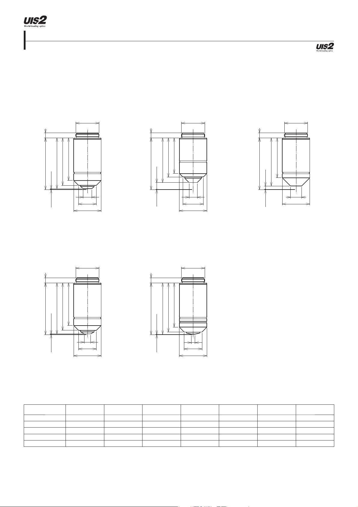
Microscope Objectives
Achromat for Polarizing
PLN-P, ACHN-P series
The PLN-P and ACHN-P are cost-ef cient objectives designed for transmitted polarized light observations.
4.5
45.06
( 44.29 )
CG=0.17 W.D.= 0.6
ACHN40XP
PLN4XP
36.9
41.3
ø
20.32
ø7.5
ø15.6
ø24
ø
20.32
ACHN10XP
4.5
30.8
34
( 38.89 )
45.06
CG= 0.17 W.D.= 6
ACHN100XOP
ø
20.32
ø7.1
ø18
ø24
ø20.32
ACHN20XP
4.5
( 41.89 )
45.06
CG= 0.17 W.D.=3
ø
20.32
34.6
ø9.6
ø24
4.5
45.06
CG= 0.17 W.D.=0 .45
Objectives
(magni cation)
36.9
41.3
( 44.44 )
ø5.6
ø15.6
ø24
NA
W.D.
(mm) *
4.5
42.8
45.06
( 44.76 )
W.D.= 0.13CG= 0.17
Cover Glass
Thickness (mm)
38.4
ø3.3
ø15.6
ø24
Immersion Spring Fluorescence ** FN
PLN4XP 0.10 18.5 — — — (BG) 22.0
ACHN10XP 0.25 6 — — — (BG) 22.0
ACHN20XP 0.40 3 0.17 — — (BG) 22.0
ACHN40XP 0.65 0.45 0.17 — Yes (BG) 22.0
ACHN100XOP 1.25 0.13 — Oil Yes (BG) 22.0
Screw: W 20.32 mm × 0.706 mm (0.8 in. × 1/36 in.)
*De ned with cover glass thickness shown as “CG” in the above drawings.
**U: UV Excitation, BG: Visible Excitation, IR: Near IR. "( )" indicates that uorescence might be slightly darker.
unit: mm
3-26
Page 44

Microscope Objectives
Plan Achromat (ND)
PLN-CY, PLFLN-CY series
The PLN-CY and PLFLN-CY standard objectives provide excellent eld atness. These objectives, equipped with neutral density (ND)
lters, provide the same level of brightness, even if the magni cation is changed, thereby removing the need for brightness adjustment.
PLN2XCY
4.5
( 39.09 )
45.06
W.D.= 5.8CG= 0.17
PLN20XCY
PLN4XCY PLN10XCY
ø
20.32
4.5
35.4
ø16.8
ø24
( 26.39 )
45.06
W.D.=18. 5
CG= 0.17
ø
20.32
22
32.7
( 34.29 )
45.06 4.5
ø15.8
ø24
W.D.=10. 6
CG= 0.17
ø
20.32
28.6
ø10.5
ø16
ø24
PLFLN10XCY
ø
20.32
ø
20.32
4.545.06
24.8
45.06 4.8
CG= 0.17 W.D.=1.2
Objectives
(magni cation)
36.9
41.3
( 43.69 )
ø6
ø15.6
ø24
NA
W.D.
(mm) *
( 34.89 )
W.D.=10
CG= 0.17
Cover Glass
Thickness (mm)
ø13.6
ø24
Immersion Spring Fluorescence ** FN
PLN2XCY 0.06 5.8 — — — — 22.0
PLN4XCY 0.10 18.5 — — — — 22.0
PLN10XCY 0.25 10.6 — — — (BG) 22.0
PLN20XCY 0.40 1.2 0.17 — — (BG) 22.0
PLFLN10XCY 0.30 9.9 — — — BG 26.5
Screw: W 20.32 mm × 0.706 mm (0.8 in. × 1/36 in.)
*De ned with cover glass thickness shown as “CG” in the above drawings.
**U: UV Excitation, BG: Visible Excitation, IR: Near IR. "( )" indicates that uorescence might be slightly darker.
unit: mm
3-27
Page 45

Microscope Objectives
Long Working Distance Universal Plan Semi Apochromat
LUCPLFLN series
The LUCPLFLN long working distance, universal objectives display at images from violet up to the near-infrared region of the spectrum.
These objectives are dedicated to tissue culture observations through bottles and dishes, offering high contrast and splendid resolution
in bright eld, DIC, and uorescence observations.
LUCPLFLN20X LUCPLFLN40X LUCPLFLN60X
ø26
ø20.32
ø26
ø20.32
ø26
ø20.32
4.7
17.4
24.4
33.1
35.5
( 36.9 )
45.34
W.D.=7.44CG= 1
ø12.1
ø21.8
ø27
4.5
17.5
24.3
35.3
39
( 40.94 )
45.34
W.D.= 3.4
ø
9.5ø9.5
CG= 1
ø19
ø26
ø29
45.34 4.5
( 42.64 )
CG= 1 W. D.=1.7
17.5
24.3
36
39.9
ø
9
ø17.4
ø26
ø29
Objectives
(Magni cation)
NA
W.D.
(mm) *
Cover Glass
Thickness (mm)
Immersion Spring Fluorescence ** FN
LUCPLFLN20X 0.45 7.8–6.6 0–2 — — U/BG/IR *** 22.0
LUCPLFLN40X 0.60 4–2.7 0–2 — — U/BG/IR *** 22.0
LUCPLFLN60X 0.70 2.2–1.5 0.1–1.3 — — U/BG/IR *** 22.0
Screw: W 20.32 mm × 0.706 mm (0.8 in. × 1/36 in.)
*De ned with cover glass thickness shown as “CG” in the above drawings.
**U: UV excitation, BG: Visible Excitation, IR : Near IR. "( )" indicates that uorescence might be slightly darker.
***IR excitation might cause the objective to go slightly out of focus.
3-28
unit: mm
Page 46
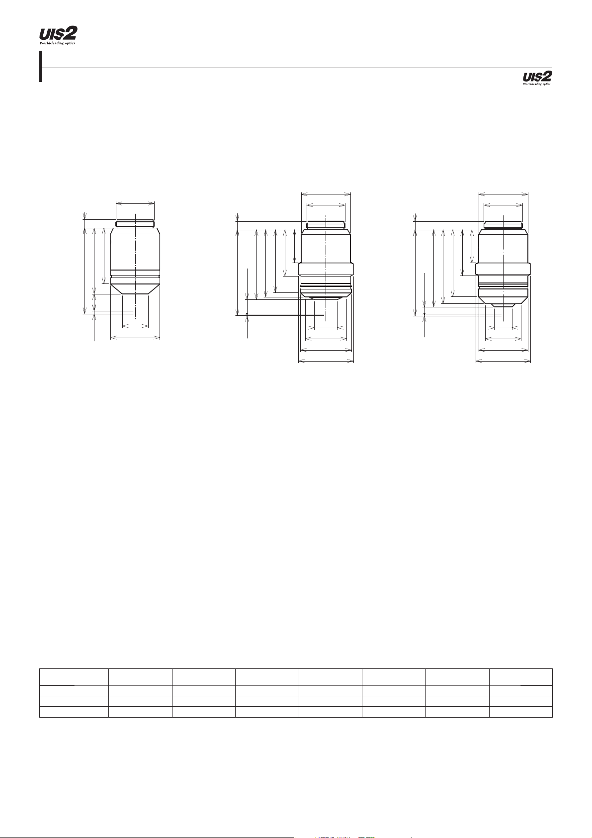
Microscope Objectives
Long Working Distance Universal Plan Semi Apochromat for Relief Contrast
CPLFLN-RC, LUCPLFLN-RC series
The CPLFLN-RC and LUCPLFLN-RC long working distance, universal objectives display at images from violet up to the near-infrared
region of the spectrum. These objectives are designed for the observation of living cells, including oocytes. Plastic
vessels can be used with these objectives for relief contrast observations.
CPLFLN10XRC LUCPLFLN20XRC LUCPLFLN40XRC
ø
20.32
ø
ø26
20.32
ø
ø26
20.32
4.5
29.4
( 35.04 )
45.54
W.D.= 9
ø13.6
CG= 1.5
ø26
4.5
17.4
24.5
33.2
35.5
( 36.9 )
45.37
ø12.1
CG= 1 W.D.=7.47
ø21.8
ø27
ø29
4.5
17.5
24.3
35.3
39
( 40.71 )
45.37
W.D.= 3.66CG = 1
ø9.5
ø19
ø26
ø29
Objectives
(magni cation)
NA
W.D.
(mm) *
Cover Glass
Thickness (mm)
Immersion Spring Fluorescence ** FN
CPLFLN10XRC 0.30 9 *** — — — BG 22.0
LUCPLFLN20XRC 0.45 7.8–6.6 0–2 — — U/BG/IR **** 22.0
LUCPLFLN40XRC 0.60 4.2–3.0 0–2 — — U/BG/IR **** 22.0
Screw: W 20.32 mm × 0.706 mm (0.8 in. × 1/36 in.)
*De ned with cover glass thickness shown as “CG” in the above drawings.
**U: UV Excitation, BG: Visible Excitation, IR: Near IR. "( )" indicates that uorescence might be slightly darker.
***De ned by 1 mm bottom thickness of a plastic container and 0.5 mm bottom thickness of a glass heat plate (depends on the shape of container).
****IR excitation might cause the objective to go slightly out of focus.
3-29
unit: mm
Page 47
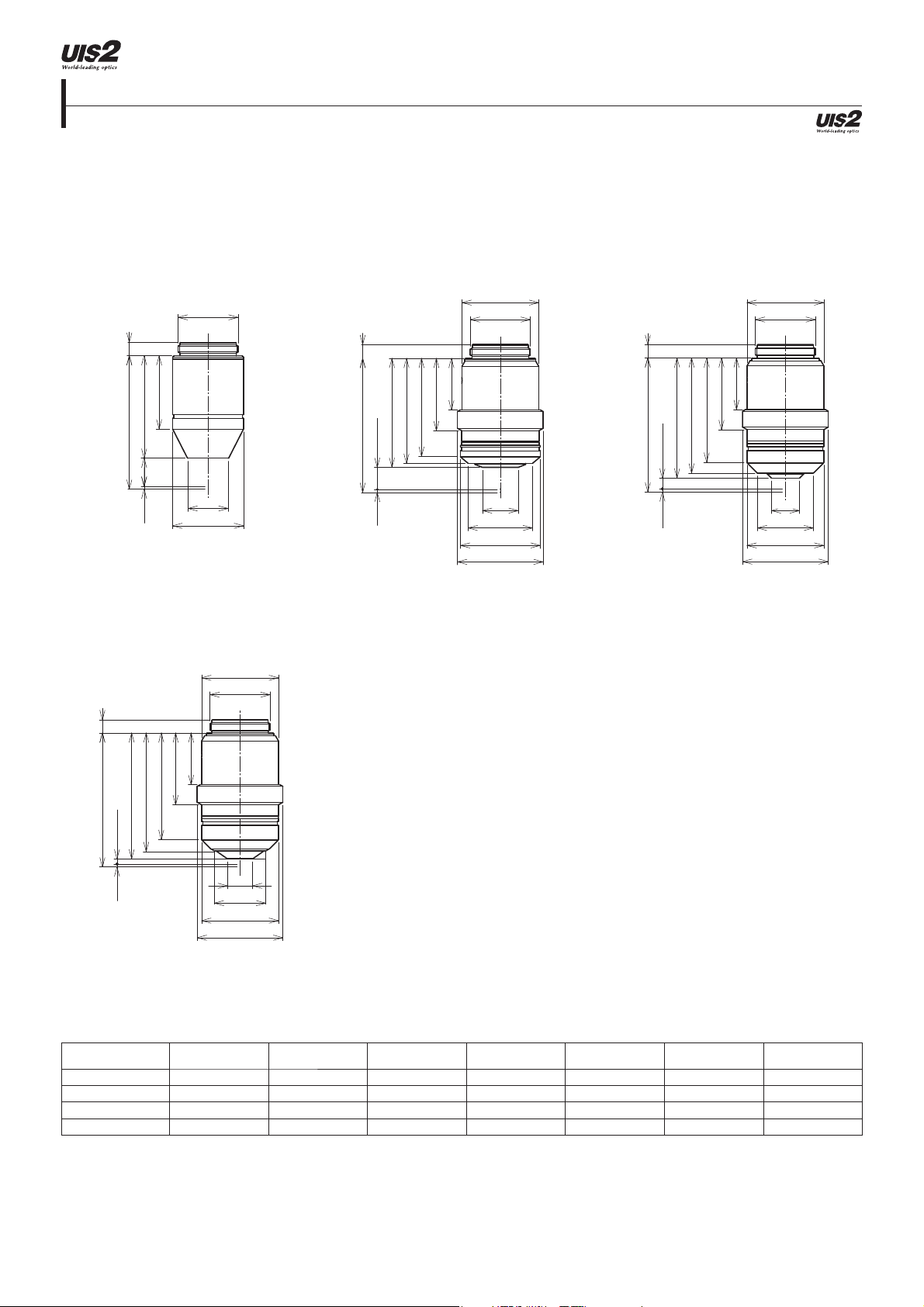
Microscope Objectives
Long Working Distance Universal Plan Semi Apochromat for Phase Contrast
CPLFLN-PH, LUCPLFLN-PH series
The CPLFLN-PH and LUCPLFLN-PH long working distance, universal objectives display at images from violet up to the near-infrared
region of the spectrum. These objectives are speci cally designed for culture specimens and are optimized to produce splendid phase
contrast images, regardless of the thickness and material of the culture vessel.
CPLFLN10XPH
ø20.32
4.5
24.8
( 34.87 )
45.37
W.D.= 9.5
ø
13.6
CG= 1
ø24
LUCPLFLN60XPH
ø26
ø
20.32
LUCPLFLN20XPH LUCPLFLN40XPH
ø26
ø20.32
4.7
17.4
24.5
33.2
35.5
( 36.9 )
45.37
ø
12.1
CG= 1 W.D.=7.47
ø21.8
ø27
ø29
4.5
35.3
39
( 40.71 )
45.37
W.D.= 3.66CG= 1
ø26
ø20.32
17.5
24.3
ø
9.5ø9.5
ø19
ø26
ø29
4.5
17.5
24.3
36.1
40.1
45.37
( 42.63 )
ø
8.5
CG= 1 W.D.=1.74
Objectives
(magni cation)
NA
ø17.4
ø26
ø29
W.D.
(mm) *
Cover Glass
Thickness (mm)
Immersion Spring Fluorescence ** FN
CPLFLN10XPH 0.30 9.5 *** 1 — — BG 22.0
LUCPLFLN20XPH 0.45 7.8–6.6 0–2 — — U/BG/IR **** 22.0
LUCPLFLN40XPH 0.60 4.2–3.0 0–2 — — U/BG/IR **** 22.0
LUCPLFLN60XPH 0.70 2.2–1.5 0.1–1.3 — — U/BG/IR **** 22.0
Screw: W 20.32 mm × 0.706 mm (0.8 in. × 1/36 in.)
*De ned with cover glass thickness shown as “CG” in the above drawings.
**U: UV Excitation, BG: Visible Excitation, IR: Near IR. "( )" indicates that uorescence might be slightly darker.
***De ned by 1 mm bottom thickness of a plastic container.
****IR excitation might cause the objective to go slightly out of focus.
unit: mm
3-30
Page 48

Microscope Objectives
Culture Specimen Objectives for Phase Contrast
CPLN-PH, LCACHN-PH series
The CPLN-PH and LCACHN-PH standard objectives provide excellent eld atness during phase contrast observation in transmitted
light.
CPLN10XPH LCACHN20XPH LCACHN40XPH
ø
20.32
4.5
28.5
32.7
( 34.37 )
45.37
W.D.=10
ø
10.5ø10.5
CG= 1
ø16
ø24
4.5
38
( 41.17 )
45.37
W.D.= 3.2CG= 1
ø
20.32
4.5
32.9
ø8
ø14.2
ø24
39.6
( 42.17 )
45.37
CG= 1 W.D.=2. 2
ø
20.32
34.5
ø6.9
ø14.2
ø24
Objectives
(magni cation)
NA
W.D.
(mm) *
Cover Glass
Thickness (mm)
Immersion Spring Fluorescence ** FN
CPLN10XPH 0.25 10 *** — — — BG 22.0
LCACHN20XPH 0.40 3.2 *** 1 — — BG 22.0
LCACHN40XPH 0.55 2.2 *** 1 — — BG 22.0
Screw: W 20.32 mm × 0.706 mm (0.8 in. × 1/36 in.)
*De ned with cover glass thickness shown as “CG” in the above drawings.
**U: UV Excitation, BG: Visible Excitation, IR: Near IR. "( )" indicates that uorescence might be slightly darker.
***De ned by 1 mm bottom thickness of a plastic container.
3-31
unit: mm
Page 49

Microscope Objectives
Culture Specimen Objectives for Relief Contrast
CPLN-RC, LCACHN-RC series
The CPLN-RC and LCACHN-RC standard objectives provide excellent eld atness during relief contrast observation in transmitted
light. These objectives are designed for the observation of living cells, including oocytes, in plastic vessels.
CPLN10XRC LCACHN20XRC LCACHN40XRC
ø
20.32
ø
ø24
20.32
ø
ø24
20.32
4.5
29.4
( 35.04 )
45.54
W.D.= 9
ø13.6
CG= 1.5
ø26
4.8
32.6
36.9
( 41.24 )
45.54
W.D.=2 .8CG= 1.5
ø8
ø17
ø25.6
4.8
34.5
38.8
( 42.14 )
45.54
ø6.9
CG= 1.5 W.D. =1.9
ø17
ø25.6
Objectives
(magni cation)
NA
W.D.
(mm) *
Cover Glass
Thickness (mm)
Immersion Spring Fluorescence ** FN
CPLN10XRC 0.25 9.7 *** — — — BG 22.0
LCACHN20XRC 0.40 2.8 *** 1.5 — — BG 22.0
LCACHN40XRC 0.55 1.9 *** 1.5 — — BG 22.0
Screw: W 20.32 mm × 0.706 mm (0.8 in. × 1/36 in.)
*De ned with cover glass thickness shown as “CG” in the above drawings.
**U: UV Excitation, BG: Visible Excitation, IR: Near IR. "( )" indicates that uorescence might be slightly darker.
***De ned by 1 mm bottom thickness of a plastic container and 0.5 mm bottom thickness of a glass heat plate (depends on the shape of container).
3-32
unit: mm
Page 50

Microscope Objectives
No Cover Water Immersion for a Fixed Stage Upright Microscope
UMPLFLN-W, LUMPLFLN-W series
The UMPLFLN, LUMPLFLN-W, and LUMFLN series of long working distance, water immersion objectives display at images from high
transmission factors up to the near-infrared region of the spectrum. These objectives achieve splendid DIC and uorescence from the
visible range to infrared and are ideal for uorescence imaging of brain tissue, as well as other tissue and specimens.
UMPLFLN10XW
ø24
ø
20.32
4.545
36.7
( 41.5 )
ø7
W.D.= 3.5
ø15.7
ø21
LUMPLFLN60XW
ø24
ø
20.32
UMPLFLN20XW LUMPLFLN40XW
ø24
ø
20.32
4.545
36.7
( 41.5 )
ø7
W.D.= 3.5
ø15.7
ø21
4.5
45
( 41.69 )
W.D.= 3.3
ø24
ø
20.32
37.3
ø7.2
ø15.8
ø21
4.5
37.8
42.7
45
( 42.95 )
W.D.=2
Objectives
(magni cation)
ø6.6
ø20
ø22
NA
W.D.
(mm) *
Cover Glass
Thickness (mm)
Immersion Spring Fluorescence ** FN
UMPLFLN10XW 0.30 3.50 0 Water — U/BG 26.5
UMPLFLN20XW 0.50 3.50 0 Water — U/BG 26.5
LUMPLFLN40XW 0.8 3 0 Water — U/BG 26.5
LUMPLFLN60XW 1.00 2 0 Water — U/BG 26.5
Screw: W 20.32 mm × 0.706 mm (0.8 in. × 1/36 in.)
*De ned with cover glass thickness shown as “CG” in the above drawings.
**U: UV Excitation, BG: Visible Excitation, IR: Near IR. "( )" indicates that uorescence might be slightly darker.
unit: mm
3-33
Page 51

Microscope Objectives
No Cover Water Immersion for a Fixed Stage Upright Microscope
XLUMPLFLN20XW
The XLUMPLFLN-W high NA, long working distance objectives display at images from high transmission factors up to the near-infrared
region of the spectrum. These objectives achieve splendid DIC and uorescence from the visible range to infrared. These objectives
enable the measurement of cell membrane electric potential since the design of the objectives provides easy access to patch clamp
electrodes.
XLUMPLFLN20XW ***
ø25
5.8
65.6
75
( 70.95 )
( 2.03 )
ø10.5
ø23.9
W.D.=2 .02
ø30
Objectives
(magni cation)
XLUMPLFLN20XW ***
Screw: W 25 mm × 0.75 mm (1 in. × 0.03 in.)
*De ned with cover glass thickness shown as “CG” in the above drawings.
**U: UV Excitation, BG: Visible Excitation, IR: Near IR. "( )" indicates that uorescence might be slightly darker.
***Special dedicated nosepiece needed (WI-SNPXLU).
****IR excitation might cause the objective to go slightly out of focus.
NA
1.00 2 0 Water — U/BG/IR **** 22.0
W.D.
(mm) *
Cover Glass
Thickness (mm)
Immersion Spring Fluorescence ** FN
3-34
unit: mm
Page 52
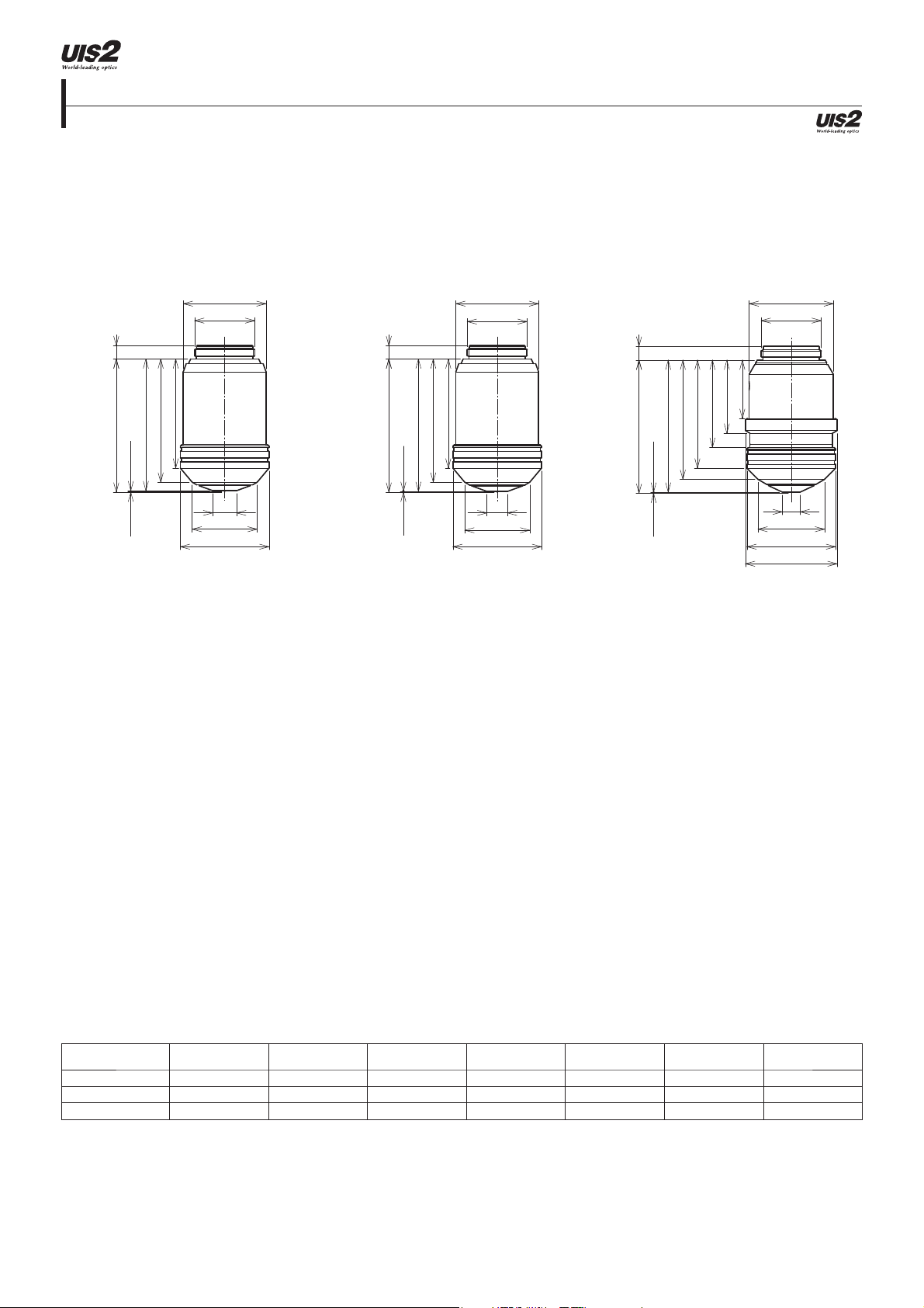
Microscope Objectives
Universal Apochromat
UAPON 340 series
The UAPON340 objectives feature high transmission of 340 nm wavelength light, providing maximum performance in uorescence
microscopes using UV excitation.
UAPON20XW340 UAPON40XO340-2 UAPON40XW340
ø28
ø20.32
ø28
ø20.32
ø28.5
ø20.32
4.5
36.9
41.7
45.06
( 44.54 )
W.D.=0.35CG= 0.17
ø8.1
ø22
ø30
4.5
36.9
41.7
45.06
( 44.79 )
W.D.= 0.1CG=0.17
ø7
ø22
ø30
4.7
19.7
24.7
29.5
36.5
40.3
45.06
( 44.64 )
ø6
ø22.5
CG= 0.17 W.D.= 0.25
ø30
ø31
Objectives
(magni cation)
NA
W.D.
(mm) *
Cover Glass
Thickness (mm)
Immersion Spring Fluorescence ** FN
UAPON20XW340 0.70 0.35 0.17 Water Yes U/BG 22.0
UAPON40XO340-2 1.35 0.1 0.17 Oil Yes U/BG 22.0
UAPON40XW340 1.15 0.25 0.13-0.25 Water Yes U/BG 22.0
Screw: W 20.32 mm × 0.706 mm (0.8 in. × 1/36 in.)
*De ned with cover glass thickness shown as “CG” in the above drawings.
**U: UV Excitation, BG: Visible Excitation, IR: Near IR. "( )" indicates that uorescence might be slightly darker.
3-35
unit: mm
Page 53

Microscope Objectives
TIRF Objectives
APON, UAPON series
These objectives feature the highest NA to create an evanescent wave eld for high-contrast TIRF images.
APON60XOTIRF
4.7
40.7
43
45.06
41.3
( 44.78 )
CG= 0.17 W .D. =0 .11
UAPON150XOTIRF
APON100XHOTIRF *** UAPON100XOTIRF
ø28
20.32
ø
4.7
22.4
26.9
45.07
( 44.84 )
ø7.8
ø
ø18.5
ø23.7
ø30.5
ø31.5
ø28
20.32
CG= 0.15 W.D.= 0.08
25.2
40.7
42.2
43.2
ø28.5
ø
20.32
4.7
19.2
43.2
45.06
( 44.8 )
W.D.= 0.09CG= 0.17
ø7.5
ø22.6
ø23.7
ø30.5
ø31.5
22.4
26.9
40.7
42.2
ø28
ø20.32
ø7.8
ø22.6
ø23.7
ø30.5
ø31.5
4.7
22.4
26.9
40.6
41.5
42.6
45.06
( 44.81 )
W.D.= 0.08CG= 0.17
ø5.6
ø18.1
ø23.3
ø30.5
ø31.5
Objectives
(magni cation)
NA
W.D.
(mm) *
Cover Glass
Thickness (mm)
Immersion Spring Fluorescence ** FN
APON60XOTIRF 1.49 0.1 0.13-0.19 Oil — (U)/BG 22.0
APON100XHOTIRF ***
1.70 0.08 0.15 Special Oil — BG 22.0
UAPON100XOTIRF 1.49 0.1 0.13-0.19 Oil — U/BG 22.0
UAPON150XOTIRF 1.45 0.08 0.13-0.19 Oil — U/BG 22.0
Screw: W 20.32 mm × 0.706 mm (0.8 in. × 1/36 in.)
*De ned with cover glass thickness shown as “CG” in the above drawings.
**U: UV Excitation, BG: Visible Excitation, IR: Near IR. "( )" indicates that uorescence might be slightly darker.
***Special dedicated cover glass and immersion oil needed.
unit: mm
3-36
Page 54

Microscope Frame
BX53M: Upright Transmitted and Re ected Light Microscope Frame
BX53MTRF-S
Designed with modularity in mind, the BX3M series provide versatility for a wide variety of material science and industrial applications.
The frames are out tted with electro-static discharge (ESD) capability to help protect electronic samples.
BX53MTRF-S
290.5
90
274.4
192
81.5
91.4
362.2
Weight: 7.6 kg Unit: mm
4-1
Page 55

Microscope Frame
BX53M: Upright Re ected Light Microscope Frame
BX53MRF-S
Designed with modularity in mind, the BX3M series provide versatility for a wide variety of material science and industrial applications.
The frames are out tted with ESD capability to help protect electronic samples.
BX53MRF-S
290.5
90
274.4
192
81.5
91.4
362.2
Weight: 7.4 kg Unit: mm
4-2
Page 56

Microscope Frame
BX3: Automated Transmitted Light Microscope Frame
BX63F
This fully motorized system enables automation of complex multidimensional experiments and features a precise motorized Z-drive and
splendid stability thanks to the xed stage design.
BX63F
110
294.4
359
90
152.5
429.2
Weight: 14.1 kg Unit: mm
4-3
Page 57

Microscope Frame
BX3: Semi-Motorized Fluorescence Transmitted Light Microscope Frame
BX53F
The entire optical path of the BX53 is designed for optimal uorescence imaging and uses UIS2 optical components that set a new
standard in precision and clarity. The modular concept enables motorization of individual components.
BX53F
90
274.4
319
97
91.4
362.2
Weight: 8.3 kg Unit: mm
4-4
Page 58

Microscope Frame
BX3: Manual System Transmitted Light Microscope Frame
BX43F
The BX43 microscope offers a wide range of features, splendid optical performance, and is the ideal platform for digital imaging. This
exible microscope offers various contrast methods and leading-edge optics combined with true-color LED illumination for true-to-life
color rendering.
BX43F
90
274.4
319
192
81.5
91.4
362.2
Weight: 9.1 kg Unit: mm
4-5
Page 59

Microscope Frame
BX3: Transmitted Light Ergonomic Microscope Frame
BX46F
The BX46 features an ergonomic design with a low-position xed stage and nosepiece focus that helps keep users comfortable while
they're working.
BX46F
90
274.4
143.864112
319.8
81.5
91.4
362.2
Weight: 9.8 kg Unit: mm
4-6
Page 60

Microscope Frame
BX2: Upright Motorized Transmitted/Re ected Frame
BX61TRF
The BX61 frame is designed to incorporate a laser-based autofocus unit for active focus tracking, making inspections faster and highly
reproducible.
BX61TRF
90
317.5
319
84
70
341.2
Weight: 11.4 kg Unit: mm
4-7
Page 61

Microscope System BXFM
BXFM Frame
BXFM-F
This popular microscope frame can be used with ber illumination, a motorized nosepiece, and a telan lens unit. The frame can easily
be integrated into other equipment, which can be attached by a rear bolt mounting screw or pillar mounting hole.
84
82
58.5
124
35
(13)
Stroke
23 7
80
36
4-M8 Depth 8
Bolt Mount Screw
36
4–M4 Depth 9
55
0.5 17 100
Pillar Mount Hole Center
66.2
2A00002
98 110
4–M4 Depth 7
ø32H8
Pillar Mount Hole
0.5
(13)
16 17 17 34
Weight: 1.9kg Unit: mm
4-8
Page 62

Microscope System BXFM
BXFM System Con guration Example 1
BXFM-F + BXFM-ILH + BXFM-ILHSPU
This example accommodates re ected light bright eld/dark eld and uorescence illuminators.
180
Light Axis
Light Axis
165
130
83
Pillar Axis
Holder Mounting Position
Revolving Nosepiece Mounting Position
72
Objective Mounting Position
Specimen Position
3.5
45 40
BXFM Combination Sample
BXFM-F + BXFM-ILH + BXFM-ILHSPU + TR30-2 + BX-RLA2 + U-LH100L-3
11
Weight: 3.2kg Unit: mm
165
130
87.5
83
220 180
587
*For installation dimensions, refer to the BXFM-F diagram.
4-9
249
Specimen
Surface
ø 32
3.5
40
45
Weight: 8.2kg (excludes objectives) Unit: mm
17-47 Stroke
11
124
Page 63

Microscope System BXFM
BXFM System Con guration Example 2
BXFM-F + BXFM-ILHS
This system example contains a compact focusing unit that is suitable for being integrated into existing equipment.
141
Pillar Axis
106
59
Holder Mounting Position
Light Axis
BXFM-S Combination Sample
BXFM-F + BXFM-ILHS + TR30-2 + U-KMAS + U-LH100L-3
106 187
Revolving Nosepiece
20
Mounting Position
Objective
Mounting Position
45 40 84
Specimen Position
7
23
Stroke
Weight: 2.4kg Unit: mm
290
ø32
124
19-49
Stroke
*For installation dimensions, refer to the BXFM-F diagram.
92.5
204045
169
Specimen Surface
84
208
Weight: 5.5 kg (excludes objectives) Unit: mm
4-10
Page 64

Microscope System BXFM
Stands for the BXFM
A wide variety of stands are available to suit different applications and purposes.
SZ2-STU2
Universal Stand Type 2
250
300
300
350
503
ø40
180º
214~435
30º
ø25
90
Ø32
622
130
Major Speci cations
Item Speci cations
Diameter of Focusing Arm or
1
Fixing Section of Tube
ø32 mm
2 Vertical Pole Diameter ø40 mm
3 Diameter of Horizontal Poles
4 Stroke
5 Movement Range
ø25 mm
(both upper and lower poles)
Horizontal: 234 mm
Vertical: 205 mm
Horizontal: 541 (435 + 106) mm max.
(vertical pole — BXFM-S optical
axis)
Forward: 10 kg
6 Maximum Specimen Weight
(within 90-degree area)
Transverse Direction: 6 kg
Backward Direction: 7 kg
(at maximum stroke)
7 Weight 30 kg
50.5
*The rotation angle of the horizontal arm can be restricted to 90 degrees with a stopper.
U-ST
Compact Stand
133
ø110
88
35
49 133
106
73 143
ø32
20
SZ-STL
Large Stand
320
160
400
ø32
267
46
45
Weight: 1.8 kg
4-11
17.5
Weight: 5 kg
Unit: mm
Page 65

Illumination Units
Re ected Light Illuminators for the BX53M Microscope
Manual illuminators for bright eld, dark eld, and uorescence applications.
BX3M-RLA-S
Re ected Light Illuminator for BF/DF for the BX53M Microscope
Accessories
Unit Name Description Weight (g)
U-25LBD Daylight Color Filter 20
U-25LBA Halogen Color Filter 20
U-25IF550 Green Filter 20
U-25L42 UV-Cut Filter 20
U-25Y48 Yellow Filter 20
U-25FR Frost Filter 20
U-25
Empty Filter (for use with user's
ø25 mm lters)
<20
U-25ND50 ND Filter 20
U-25ND25 ND Filter 20
U-25ND6 ND Filter 20
84
3.5
Illuminator
Mounting
Position
127
Revolving
Nosepiece
Mounting
Position
(108)
54
41
327.5
338.1
88
ø75
38.756.829.4
265
45
BF Re ected LED Light Illuminator for the BX53M Microscope
Accessories
Unit Name Description Weight (g)
U-AN-2 Fixed Analyzer 50
U-AN360-3 Rotatable Analyzer 79
U-PO3 Fixed Polarizer 71
U-POTP3 Fixed Polarizer (use with U-DICRH) 71
U-25LBD Daylight Color Filter 20
U-25LBA Halogen Color Filter 20
U-25IF550 Green Filter 20
U-25L42 UV-Cut Filter 20
U-25Y48 Yellow Filter 20
U-25FR Frost Filter 20
U-25
U-25ND50 ND Filter 20
U-25ND25 ND Filter 20
U-25ND6 ND Filter 20
Empty Filter (for use with user's
ø25 mm lters)
<20
BX3M-KMA-S
Revolving
84
Nosepiece
Mounting
Position
3.5
Illuminator
Mounting
Position
108
Weight: 3.0 kg
88
ø75
54
16
41
236
298.5
5-1
Weight: 2.4 kg
Unit: mm
Page 66

Illumination Units
Coded Re ected Light Illuminator for the BX53M Frame
Coded illuminators require users to physically change the device's settings, but the microscope's software automatically recognizes
these changes.
BX3M-RLAS-S
Coded Re ected Light Illuminator for BF/DF for the BX53M Frame
Accessories
Unit Name Description Weight (g)
U-AN-2 Fixed Analyzer 50
U-AN360-3 Rotatable Analyzer 79
U-PO3 Fixed Polarizer 71
U-POTP3 Fixed Polarizer (use with U-DICRH) 71
U-25LBD Daylight Color Filter 20
U-25LBA Halogen Color Filter 20
U-25IF550 Green Filter 20
U-25L42 UV-Cut Filter 20
U-25Y48 Yellow Filter 20
U-25FR Frost Filter 20
U-25
Empty Filter (for use with user's
ø25 mm lters)
<20
U-25ND50 ND Filter 20
U-25ND25 ND Filter 20
U-25ND6 ND Filter 20
84
3.5
Illuminator
Mounting
Position
Revolving
Nosepiece
Mounting
Position
161.4
(150)
ø78.8
75
37.489.1
38
64
394.7
285
88
Coded Universal Re ected Illuminator for the BX53M Frame
Accessories
Unit Name Description Weight (g)
U-AN-2 Fixed Analyzer 50
U-AN360-3 Rotatable Analyzer 79
U-PO3 Fixed Polarizer 71
U-POTP3 Fixed Polarizer (use with U-DICRH) 71
U-25LBD Daylight Color Filter 20
U-25LBA Halogen Color Filter 20
U-25IF550 Green Filter 20
U-25L42 UV-Cut Filter 20
U-25Y48 Yellow Filter 20
U-25FR Frost Filter 20
U-25
U-25ND50 ND Filter 20
U-25ND25 ND Filter 20
U-25ND6 ND Filter 20
Empty Filter (for use with user's
ø25 mm lters)
<20
BX3M-URAS-S
(150)
151.2
Revolving
84
Nosepiece
Mounting
Position
3.5
Illuminator
Mounting
Position
Weight: 3.6 kg
88
ø84
75
26.887.1
38
40
371
261
5-2
Weight: 3.2 kg
Unit: mm
Page 67

Illumination Units
Re ected Illuminator for the BX3 Series
Manual illuminators for bright eld, dark eld, and uorescence applications.
BX3-URA
Universal Re ected Illuminator for the BX3 Series
A total of eight uorescence mirror units can be attached for multi color uorescence observations.
Accessories
Unit Name Description Weight (g)
U-AN-2 Fixed analyzer 50
U-AN360-3 Rotatable analyzer 79
U-PO3 Fixed polarizer 71
U-POTP3 Fixed polarizer (use with U-DICRH) 71
U-25LBD Daylight color lter 20
U-25LBA Halogen color lter 20
U-25IF550 Green lter 20
U-25L42 UV-cut lter 20
U-25Y48 Yellow lter 20
U-25FR Frost lter 20
U-25
Empty lter, for use with user's ø25
mm lters
<20
U-25ND50 ND lter 20
U-25ND25 ND lter 20
U-25ND6 ND lter 20
84
3.5
Illuminator
Mounting
Position
Revolving
Nosepiece
Mounting
Position
(180)
90
38
86.2 28.9
261
402.5
88
ø84
40
Coded Fluorescence Illuminator for the BX3 Series
The eight uorescence mirror units feature coded functionality.
Accessories
Unit Name Description Weight (g)
U-AN-2 Fixed analyzer 50
U-AN360-3 Rotatable analyzer 79
U-PO3 Fixed polarizer 71
U-POTP3 Fixed polarizer (use with U-DICRH) 71
U-25LBD Daylight color lter 20
U-25LBA Halogen color lter 20
U-25IF550 Green lter 20
U-25L42 UV-cut lter 20
U-25Y48 Yellow lter 20
U-25FR Frost lter 20
U-25
U-25ND50 ND lter 20
U-25ND25 ND lter 20
U-25ND6 ND lter 20
Empty lter, for use with user's ø25
mm lters
<20
BX3-RFAS
Revolving
84
Nosepiece
Mounting
Position
3.5
Illuminator
Mounting
Position
(180)
Weight: 3.8 kg
88
ø84
90
86.2 42.8
38
402.5
261
40
5-3
Weight: 3.9 kg
Unit: mm
Page 68

Illumination Units
Re ected Light Illuminator for the BX2 Series
BX-RLA2
Re ected Light Illuminator for BF/DF
Neutral density (ND) lters are linked when exchanging between bright eld and dark eld.
Accessories
Unit Name Description Weight (g)
U-25LBD Daylight Color Filter 20
U-25IF550 Green Filter 20
U-25ND6 ND Filter 20
U-25ND25 ND Filter 20
U-25FR Frost Filter 20
U-25L42 UV-Cut Filter 20
U-PO3 Fixed Polarizer 71
U-POTP3 Fixed Polarizer (use with U-DICRH) 71
U-AN360-3 Rotatable Analyzer 79
U-AN Analyzer Slider for Re ected Light 50
U-DICR DIC Slider for Re ected Light 130
U-DICRH
U-DICRHC
DIC Slider for Re ected Light
(Resolution Type)
DIC Slider for Re ected Light
(Contrast Type)
130
130
This illuminator is optimized for observations ranging from bright eld to uorescence.
Six mirror units can be simultaneously attached to this re ected light illuminator.
108
Revolving
Nosepiece
Mounting
Position
Illuminator
Mounting
Position
84
41
3.5
BX-URA2
Universal Re ected Light Illuminator
31.5144
3046
88
ø75
12
335
11.8
38.7
265
16.2
13
45
1726
56.829.4
30107.5
17.5
35
7.5
Weight: 3.4 kg
Accessories
Unit Name Description Weight (g)
U-25LBD Daylight Color Filter 20
U-25IF550 Green lter 20
U-25ND6 ND Filter 20
U-25ND25 ND Filter 20
U-25FR Frost Filter 20
U-25L42 UV-Cut Filter 20
U-PO3 Fixed Polarizer 71
U-POTP3 Fixed Polarizer (use with U-DICRH) 71
U-AN360-3 Rotatable Analyzer 79
U-AN Analyzer Slider for Re ected Light 50
U-DICR DIC Slider for Re ected Light 130
U-DICRH
U-DICRHC
DIC Slider for Re ected Light
(Resolution Type)
DIC Slider for Re ected Light
(Contrast Type)
130
130
U-MBF3 Mirror Unit for Re ected Bright eld 80
U-MDF3* Mirror Unit for Re ected Dark eld 80
U-MDIC3 Mirror Unit for Re ected DIC 80
U-MBFL3
U-MWUS3
U-MWBS3
U-MWGS3
Mirror Unit for Re ected Bright eld,
for a High Intensity Light Source
Fluorescence Mirror Unit for
Re ected (U Excitation)
Fluorescence Mirror Unit for
Re ected (B Excitation)
Fluorescence Mirror Unit for
Re ected (G Excitation)
80
80
80
80
84
3.5
Illuminator
Mounting
Position
(152)
76
Revolving
Nosepiece
Mounting
Position
88
ø84
17
(17.9)
41
135
86.8
11.6
367
11.6
261
12
27.2
41
Weight: 3.8 kg
Unit: mm
5-4
Page 69

Illumination Units
Mounting Dimensions of Illuminator (BX3M-RLA-S, BX3M-RLAS-S, BX3M-URAS-S, BX3M-KMA-S, BX3-RFAS, BX3-URA)
174Distance to the Light Axis
144
100±0.1
32±0.1
4-M5 Depth 12 or more
62
R
Location
R60
Face
凸3.5
48
62±0.1
45°
37± 0
Revolving Nosepiece Relief Dimension
45 Location Face
47.3
Revolving Nosepiece Relief Dimension
Fix illuminator using four M5 screws and projection for fastening.
Mounting Dimensions of Illuminators (BX-RLA2 and BX-URA2)
21
Distance to the Light Axis
Location Face
170
52
Revolving Nosepiece Relief Dimension
(11)
89.2
100 (0.1)
Location Face
(6)
Unit: mm
36 (0.1)
2
5.5
3.5
5
2.5
Location Face
Less than R6
4-M5 Depth 12 or more
62 (0.1)
45 (10')
37 0.1
45 Location Face
(6)
Convex Section (2-4) for Positioning
Revolving Nosepiece Relief Dimension
Fix illuminator using four M5 screws and projection for fastening.
82
Unit: mm
5-5
Page 70

Illumination Units
Compact Re ected Light Illuminator for BF
U-KMAS
Very compact re ected light illuminator with reduced depth.
U-KMAS
Accessories
Unit Name Description Weight (g)
U-25LBD Daylight Color Filter 20
U-25IF550 Green Filter 20
U-25ND6 ND Filter 20
U-25ND25 ND Filter 20
U-25FR Frost Filter 20
U-25L42 UV-Cut Filter 20
U-PO3 Fixed Polarizer 71
U-POTP3 Fixed Polarizer (use with U-DICRH) 71
U-AN360-3 Rotatable Analyzer 79
U-AN Analyzer Slider for Re ected Light 50
U-DICR DIC Slider for Re ected Light 130
U-DICRH
U-DICRHC
DIC Slider for Re ected Light
(Resolution Type)
DIC Slider for Re ected Light
(Contrast Type)
130
130
88
64
21
6
155
198
ø75
21
Weight: 1.2 kg
5-6
Unit: mm
Page 71

Light Source Units
LED Lamp Housing for the BX53M Microscope
The BX3M microscope utilizes a high-intensity white LED light source for both re ected and transmitted light. High-intensity light
support various observation modes such as BF, DF, DIC, and polarizing.
BX3M-LEDR
LED Lamp Housing for BX3M Re ected
ø79
ø59
52
63.5
Weight: 0.5 kg
BX3M-LEDT
LED Lamp Housing for BX3M Transmitted
ø68
ø59
65.5
77
BX3M-PSLED
Power Supply for LED Lamp House (required with the BXFM)
Weight: 0.5 kg
82
85
11142.6
124.2
Weight: 0.36 kg
Unit: mm
6-1
Page 72

Light Source Units
LED Lamp Housing for the BX3 Series
The BX3M microscope utilizes a high-intensity white LED light source for both re ected and transmitted light. High-intensity light
support various observation modes such as BF, DF, DIC, and polarizing.
U-LHLEDC
LED Lamp Housing for BX3M Transmitted
ø68
ø54
ø48
16.5
41.5
86.5
57
U-LEDPS
External Power Supply for U-LHLEDC
The BX3 utilizes LED illumination that provides true color reproduction and an optimized
color temperature, enabling consistent color reproduction for bright eld stains.
Weight: 0.5 kg
129.5
120
185
45
48
Weight: 0.78 kg
Unit: mm
6-2
Page 73
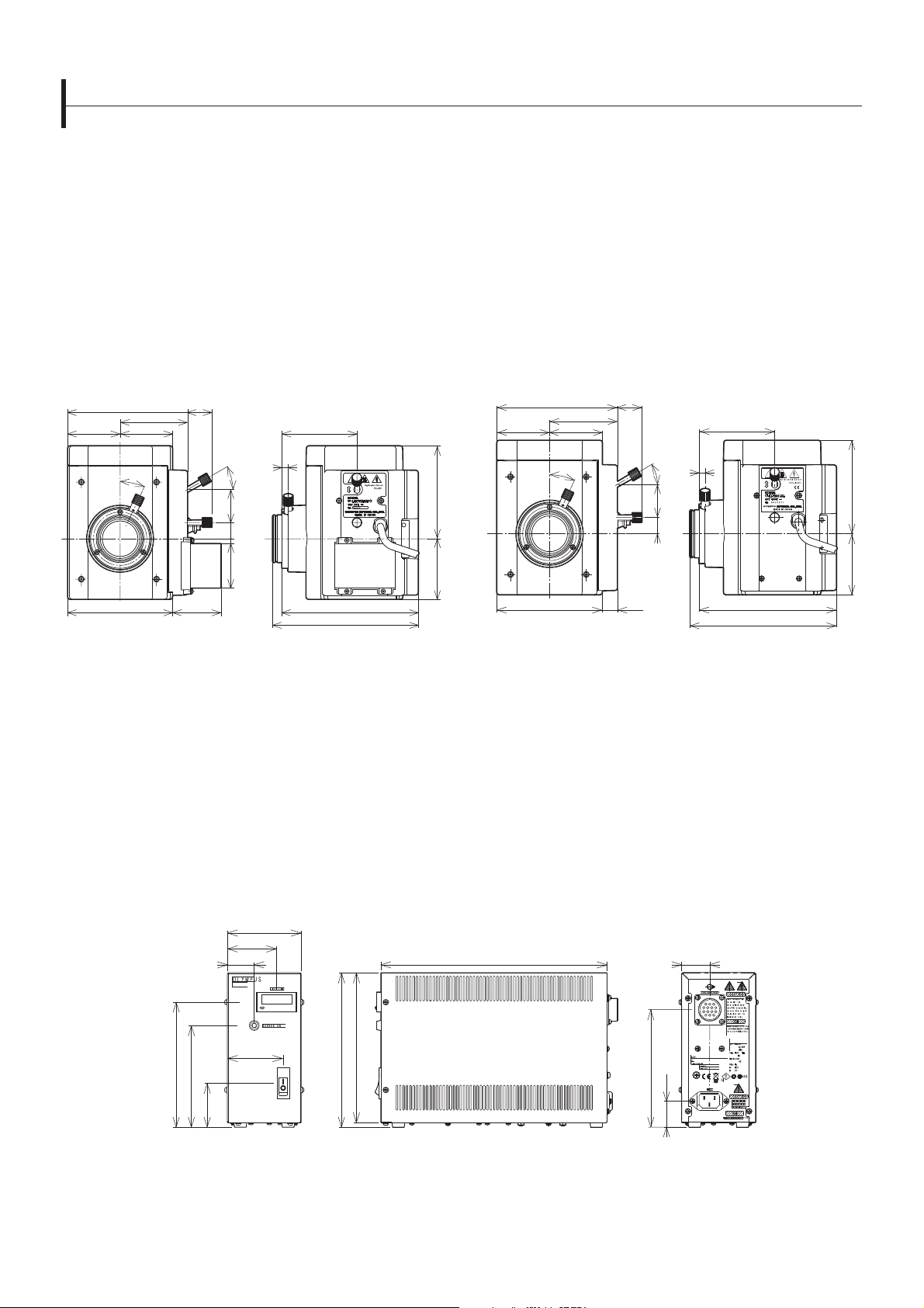
Light Source Units
Lamp Housings
A variety of different lamp housings are available for use with different light sources, enabling users to choose the most appropriate
housing for their application.
For customers who use these units in a production line, please consult your nearest Olympus representative to discuss your speci c needs.
U-LH75XEAPO
75 W Xenon Apo Lamp Housing
(148.5)
83.5
6565
25
* Power supply unit (U-RX-T) and power cable (UYCP) are required for the
75W xenon lamp housing. These items are sold separately.
Cable Length : 2,000 mm Accepted Lamp: USH-103OL Weight: 2.7 kg
30.2
70130
93
8
30
40.820
55 6
169 (depth dimension for installation)
180.5
U-LH100HGAPO
100 W Mercury Apo Lamp Housing
U-LH100HG
100 W Mercury Lamp Housing
(30.2)(148.5)
83.5
130
65
25
30
40.8
20
18.5
65
11575
* Power supply unit (U-RFL-T) and power cable (UYCP) are required for the
100W mercury lamp housings. These items are sold separately.
Cable Length : 2,000 mm Accepted Lamp: USH-103OL Weight: 2.7 kg
93
8
169
(depth dimension for installation)
180.5
11575
150
122
U-RFL-T
Power Supply Unit for Mercury Lamp
U-RX-T
Power Supply Unit for Xenon Lamp
90 1
58.2
115
31
31
Weight: Approximately 3 kg
Unit: mm
31.2
65.7
186±1
180±1
53
2701
6-3
Page 74

Light Source Units
Halogen Illumination
The external power supply for the 100 W halogen lamp (TH4-100/200) features an intensity adjustment knob and an on/off switch, both
located close to the operator’s hand for splendid comfort.
For customers who use these units in a production line, please consult your nearest Olympus representative to discuss your speci c needs.
Illumination devices for microscopes have suggested lifetimes. Periodic inspections are required. Please visit our website for details.
U-LH100-3/U-LH100IR/U-LH100L-3
100 W Halogen Lamp Housings
125
Depth Dimension for Installation
135
146.5
Cable Length U-LH100-3: 290 mm
85.5 10737
Accepted Lamp: 12V100WHAL (high-intensity lamp)
* External power supply (TH4-100 or TH4-200) and
power cable (UYCP) are required for 100 W halogen
lamp housings. These items are sold separately.
U-LH100IR: 290 mm
U-LH100L-3: 800 mm
12V100WHAL-L (long-life lamp)
TH4-100/200 TH4-HS
External Power Supply Hand Switch
Cable Length:
2,000 mm
120
77
Weight: 880 g
18.5
14.575 200
42 38
Weight: 2.2 kg Weight: 140 g
U-RMT
Extension Cord
1,700
Weight: 200 g
Unit: mm
6-4
Page 75
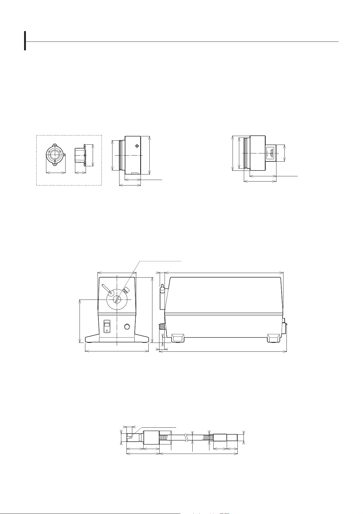
Light Source Units
Halogen Fiber Illumination Accessories
All Olympus re ected light illuminators can be used with ber illumination.
For customers who use these units in a production line, please consult your nearest Olympus representative to discuss your speci c needs.
Illumination devices for microscopes have suggested lifetimes. Periodic inspections are required. Please visit our website for details.
DF Converter for BX-URA2
Tube to exclude darkeld light
(built into the BX-URA2).
2137.5
U-RCV
43
ø59
76
ø75
31.5 Dimensions
for installation
(42.5)
Weight: 315 g Light Guide Mount Hole ø12; Weight: 390 g
ø
15
Light Guide Mounting Position
LG-PS2*
Light Source
8
U-LGAD
Fiber Adaptor for Re ected Light Observation
235
ø67
ø59
51 Dimension
for installation
62.5
ø32
130
86
126
*The types of models in use varies by country.
Groove: Width 3, Depth 1
10
ø15
30
31
61
10
10
LG-SF
Light Guide
ø25
ø10.1
1,000
ø13
251
Weight: 1.6 kg
ø12
25
20
Weight: 210 g
Unit: mm
6-5
Page 76

Light Source Units
Lamp Housing Accessory
Two lamp housings can be attached simultaneously.
For customers who use these units in a production line, please consult your nearest Olympus representative to discuss your speci c needs.
U-DULHA
Double Lamp House Adaptor
82
202
88
ø140
171
Weight: 1.2 kg
6-6
Unit: mm
Page 77

Condenser Units
Universal Condenser
U-UCD8-2
The universal condenser contains 8 optical element slots.
*Optical elements are required. Please consult your local Olympus representative for information about different optical element combinations.
U-UCD8-2
131
128.5
112
149.8
44.1
67.6
7-1
Weight: 700 g
Unit: mm
Page 78

Condenser Units
Condenser
Condensers for different applications: bright eld, dark eld, and long working distance.
U-AC2-7
Abbe Condenser
ø62
ø38
ø16
ø47
ø62
ø68
4.3
(0.119)
25.3
42.8
50.3
51.8
59.8
Weight: 174 g Weight: 380 g
WI-OBCD
Long Working Distance Oblique Condenser
ø66
ø45
ø24
U-LWCD
Long Working Distance Condenser
ø62
ø36
ø47
ø62
ø68
47.528
34
(0.2)
10.5
17.2
34.3
41.8
43.3
79.8
ø8
16
30
ø47
ø66
ø46
ø41
ø36.8
ø36
ø28
ø44
ø61.5
41.4
34
45
26
48.1
56
(56.2)
Weight: 530 g
CH3-CD
Bright eld Condenser
(0.3)
6.8
13.8
25
26.3
41.8
44.3
5
5.4
40
Weight: 60 g
Unit: mm
7-2
Page 79

Observation Tubes
Super Wide eld Trinocular Observation Tubes
Trinocular observation tubes with a super-wide eld of view. These tubes are compatible with objectives up to FN 26.5.
U-SWTR-3
Super Wide eld Trinocular Tube
180.8
14
63.1
42 0' 0"
20 0' 0"
82.3*
173.8
220.8
MX-SWETTR
Super Wide eld Erect Image Tilting Trinocular Tube
117.223
61.981
318.527
149.081
70.330
79.6
98.8
55.6
49.968.6
139.400
95.929
88.000
101.929
Name FN
2.837
Inclination Angle
(degrees)
328.338
337.718
Interpupillary Distance
(mm)
Light Path Selector
(eyepiece/video port)
72.200
Observation Image
Weight
U-SWTR-3 26.5 24 50–76 100/0, 20/80, 0/100 Inverted 2300
MX-SWETTR 26.5 0–42 50–76 100/0, 0/100 Erect 4200
*Length marked with an asterisk (*) may vary according to interpupillary distance. The distance for the gure shown is 62 mm.
8-1
Unit: mm
(g)
Page 80

Observation Tubes
Wide eld Trinocular Observation Tubes
Trinocular observation tubes with wide eld of view. These tubes are compatible with objectives up to FN 26.5.
U-TR30-2
Wide eld Trinocular Tube
Wide eld Erect Image Trinocular Tube
U-ETR-4
U-TR30IR
Wide eld Trinocular Tube for IR
175
33.5 16 120
18
59.65
92.5* (IR: 93.9)
60.6
150.5
186.6 (IR: 188.9)
Name FN
U-TR30-2 22 30 50–76 100/0, 20/80, 0/100 Inverted 1600
U-TR30IR 22 30 50–76 100/0, 0/100 Inverted 1600
U-ETR-4 22 30 50–76 100/0, 0/100 Erect 1900
*Length marked with an asterisk (*) may vary according to interpupillary distance. The distance for the gure shown is 62 mm.
43.5
Inclination Angle
(degrees)
47.9
62.5 (IR: 64.5)
95.8
Interpupillary Distance
(mm)
92
Light Path Selector
(eyepiece/video port)
163.1
199.9
Observation Image
51.6
62.5
103.9
Weight
104.9
Unit: mm
(g)
Single Port Tube with Lens
When visual observation is not needed and only video observation is required, a single port tube with a built-in telan lens can be
attached directly to the video port.
U-TLU
Single Port Tube with Lens
U-TLUIR
Single Port Tube with Lens for IR
ø60
57.6
• For attachable video camera adaptors, refer to the video camera adaptors system diagram (pages 2-12 and 2-13).
8-2
Weight: 350 g Unit: mm
Page 81

Observation Tubes
Tilting Binocular Tube
U-TTBI
Telescopic Tilting Binocular Tube
62
110.8
62
118.3
317.2
25º
234.5 19
178 130
104.4
167.7
201.240.8
45
219.5
149.545
35º
180
º
5
82
U-TTR-2
Tilting Trinocular Tube
178.6
203
218
220
236
160
142.5
66
U-TBI-3
Tilting Binocular Tube
62
5°–35°
Name FN
Inclination Angle
(degrees)
Interpupillary Distance
(mm)
U-TTBI 22 0–25 50–76 NA Inverted 3800
U-TTR-2 22 5–35 50–76 100/0, 0/100, 50/50 Inverted 3200
U-TBI-3 22 5–35 50–76 NA Inverted 1300
*When combined with the CX-RFA-2, the eld number is reduced to 18.
111
40.1136.2
16
22
Light Path Selecter
(eyepiece/video port)
Observation Image
Weight
Unit: mm
(g)
8-3
Page 82

Observation Tubes
Binocular Tube
U-CBI30-2
Binocular Tube
92.5
144.9
181.4
U-CTR30-2
Trinocular Tube
93.3 93.9
49.5
43.868.1
94
49.5
51.3
106.2
Observation Image
Weight
Name FN
92.5
Inclination Angle
(degrees)
144.9
181.4
Interpupillary Distance
(mm)
4468.4
Light Path Selector
(eyepiece/video port)
U-CBI30-2 20, 18(*) 30 48–75 NA Inverted 800
U-CTR30-2 20, 18(*) 30 48–75 NA Inverted 900
*When combined with the CX-RFA-2, the eld number is reduced to 18.
8-4
Unit: mm
(g)
Page 83

Intermediate Tubes and Accessories
Intermediate Tubes
Olympus makes various accessories to satisfy a wide variety of observation needs.
U-CA
Magni cation Changer
Provides 1X, 1.2X, 1.6X, and 2X intermediate magni cations.
ø138
96 42
ø70
ø75
45
42
U-ECA
Magni cation Changer 2C
Provides 1X and 2X intermediate magni cations.
U-ECA1.6X
Magni cation Changer 1.6X
Provides 1X and 1.6X intermediate magni cations.
88
ø140
150
37
52
Weight: 1.3 kgWeight: 1.3 kg
U-TRU
Trinocular Intermediate Attachment
The intermediate attachment divides the light path,
enabling users to attach both digital and video cameras.
183.9
ø140
106.9
52 37 150
BI:PT=100:0/20:80
58.2
Weight: 1.3 kg
9-1
Unit: mm
Page 84

Intermediate Tubes and Accessories
Intermediate Tubes
Olympus makes various accessories to satisfy a wide variety of observation needs.
U-DP
Dual Port
Use this intermediate tube to divide the light path.
88
ø140
15157
51
38
Light path selector via mirror unit
Transmitted Side Port: Side Port = 100:0
Transmitted Side Port: Side Port = 70:30 (with use of U-MBF3)
Mount Face
Weight: 1 kg
U-DP1XC
Dual Port 1X
Combine this component with the U-DP to obtain a 1X image.
17.53
ø44
ø25
170.5
Mount Face
182
4.5
ø30
1-32UN
Weight: 500 g
ø44
U-EPA2
Eyepoint Adjuster
This component rases the eyepoint by 30 mm.
89
88
30
Weight: Approximately 500 g Weight: 1.2 kg
45
Tolerance from Light Axis
15V0.2A
U-APT
Arrow Pointer
0.92
120
(8)
21.2 115
(45)
45.3
Unit: mm
9-2
Page 85

Intermediate Tubes and Accessories
Dual port tube with C-mounts
U-DPCAD
The dual camera port enables the user to attach two cameras.
U-DPCAD
50
35
n25.4
n34
n45
31.5
(94.5)
116.47
79
41.47
ø45
ø25.4
41.543
52.5
23
ø42.3
ø54
111
119
9-3
Weight: 0.9 kg Unit: mm
Dual port tube with C mounts
Page 86

Eyepieces
Eyepieces
Eyepieces for the UIS2 optical system.
WHN10X WH15X
Wide eld Eyepiece Wide eld Eyepiece
WHN10X-H
CROSSWHN10X
Wide eld Eyepieces
39.6
ø41
ø38.5
ø30
28(23.1)
51.2
48.6
39.4
ø41
ø38.5
ø30
27.8(23.2)
62.6
48.6
29.6
ø41
ø36.5
EP
ø30
SWH10X-H
MICROSWH10X
CROSSSWH10X
Super Wide eld Eyepieces
(25) 18.7
36.8
43.7
ø46.2
ø43.2
ø39
EP
53.2
ø30
Name FN
41.4
(28.5)
69.9
60.2
Diopter Adjustment Range
(1/m)
Micrometer Diameter
(mm)
Weight
(g)
Remarks
WHN10X 22 — 24 90
WHN10X-H 22 -8–+5 24 170 With adjustable diopter
CROSSWHN10X 22 -8–+5 — 170 With cross lines and adjustable diopter
WH15X 14 — 24 90
SWH10X-H 26.5 -8–+2 — 210 With adjustable diopter
MICROSWH10X 26.5 -8–+2 — 210 With micrometer and adjustable diopter
CROSSSWH10X 26.5 -8–+2 — 210 With cross lines and adjustable diopter
*EP=eyepoint
unit: mm
10-1
Page 87

Revolving Nosepieces
Revolving Nosepieces for BF Objectives
Users can choose from the 6 revolving nosepieces for BF objectives shown below. For motorized nosepieces, please refer to the
motorized unit page.
U-5RE-2
Quintuple Revolving Nosepiece
(87.4)
ø84
Weight: 520 g Weight: 800 g Weight: 0.7 kg
40.8
40
26.5 60.9
U-D6RE
Septuple Revolving Nosepiece
with Slider Slot for DIC
83
(114.4)
38 76.4
40
48.2
ø102.4
104
ESD-Resistant Sextuple Revolving
Nosepiece with Slider Slot for DIC
40
48.2
U-D6RE-ESD
104
(114.1)
38 76.1
ø102
U-D7RE
Sextuple Revolving Nosepiece
with Slider Slot for DIC
(125.6)
ø116.5
47.2
38 87.6
40
U-P4RE
Centerable Quadruple Revolving
Nosepiece with Slider Slot for DIC
116.5
38
40
48.2
Weight: 980 g Weight: 1 kg Weight: 1 kg
(114.4)
76.4
ø102.4
104
Insert the DIC dummy when not using the DIC slider.
Centerable Sextuple Revolving
Nosepiece with Slider Slot for DIC
40
47.2
U-P6RE
(125.6)
38 87.6
ø116.5
unit: mm
116.5
11-1
Page 88

Revolving Nosepieces
Revolving Nosepieces for BF/DF Objectives
Users can choose from the following 3 types of revolving nosepieces for BF/DF objectives. To attach bright eld objectives, users must
use the BF adaptor (BD-M-AD). For motorized nosepieces, please refer to the motorized unit page.
U-5BDRE U-D5BDRE
Quintuple Revolving Nosepiece for BF/DF Quintuple Revolving Nosepiece for
BF/DF with Slider Slot for DIC
104
(114.4)
48.2
34.8 76.4
40
(111.2)
48.2
38 76.4
40
104
U-P5BDRE
Centerable Quintuple Revolving
Nosepiece with Slider Slot for DIC
U-D6BDRE
Sextuple Revolving Nosepiece for
BF/DF with Slider Slot for DIC
JAPAN
(125.6)
47.2
38 87.6
40
U-D6BDRE
2A00002
JAPAN
116.5
ø102.4
102.4
ø
Weight: 800 g Weight: 800 g Weight: 1 kg
Ø116.5
Insert the DIC dummy when not using the DIC slider.
BD-M-AD
Adaptor to Mount BF Objectives
W 26 mm × 0.706 mm (1 in. × 0.03 in.)
W 20.32 mm × 0.706 mm (0.8 in. × 0.03 in.)
0
+0.2
ø30
ø28.2
(4) 4
11-2
8
Weight: 10 kg
unit: mm
Page 89

Revolving Nosepieces
Coded Sextuple Revolving Nosepiece
Coded nosepieces for BF, DF, and DIC applications.
U-D6RES U-D6BDRES-S
Coded Sextuple Revolving Nosepiece
with Slider Slot for DIC
34
(126.1)
88
76
Weight: 0.7 kg Weight: 0.9 kg Weight: 0.75 kg
48.2
38.1
40
ø104
Coded Sextuple BF/DF Revolving
Nosepiece with Slider Slot for DIC
34
(134.5)
96.5
87.5
86.438
47.4
U-D5BDRES-ESD
ESD-Resistant Coded Quintuple BF/DF
Revolving Nosepiece with Slider Slot for
DIC
116.4
34
(126.1)
88.1
76.1
48.5
38
40
ø104
U-D7RES
Coded Septuple Nosepiece with Slider Slot for DIC
116.4
(134.5)
96.5
87.638
40
47.2
ø116.4
11-3
unit: mm
Page 90

Video Camera Adaptors
C-Mount Video Camera Ports
Enables users to directly attach a C-mount video camera. Five types are provided: 1X, 0.63X, 0.5X, 0.35X and 0.25X. All models feature
a focus adjustment function.
U-TV0.25XC
C-Mount Video Port with 0.25X Lens
ø36
ø
ø64
1–32 UN
3.5
147.3
156.84
60
Weight: 1.2 kg
Image Plane
17.53
U-TV0.63XC
C-Mount Video Port with 0.63X Lens
U-TV0.35XC-2
C-Mount Video Port with 0.35X Lens
ø60
1–32 UN
4
12.4
22.4
Weight: 100 g
Image Plane
17.53
U-TV1XC
C-Mount Video Port with 1X Lens
U-TV0.5XC-3
C-Mount Video Port with 0.5X Lens
ø30
ø60
1–32 UN
30.1
3.5
32.6
42.1
Weight: 200 g
Image Plane
17.53
17.53
Projection Area
ø30
Image Plane
1002A0 0
ø60
Field of View (FN)
1–32 UN
68.75 3.5
78.25
Weight: 430 g
2/3" CCD
1/2" CCD
Image Plane
17.5
84.5 4
SN
3 G 0 0 7 0 7
TOKYO, JAPAN
ø66.5
Video Camera Adaptor
(projection lens)
94.5
Weight: 300 g
Projection
Magni cation
Projection Area (FN)
2/3" CCD 1/2" CCD 1/3" CCD
U-TV1X-2 1X 11 8 6
U-TV1XC 1X 11 8 6
U-TV0.63XC 0.63X 17.5 12.7 9.5
U-TV0.5XC-3 0.5X 22 16 12
U-TV0.35XC-2 0.35X — 22 17.1
U-TV0.25XC 0.25X — — 24
Practical Field of View (mm) =
Projection Area (FN)
Objective Magni cation
Adjust the focus on the video camera adaptor to help keep the eyepiece image in focus when switching magni cation.
Typically, the video camera adaptor is focused by switching to a low magni cation after focusing at a high magni cation.
12-1
Unit: mm
Page 91

Video Camera Adaptors
Video Camera Mount Adaptors
These video camera mount adaptors enable users to attach cameras with C, bayonet, Sony, and F-mounts. Use these adaptors with
the U-TV1X-2. Focus by amount of screwing into U-TV1X-2.
U-CMAD3
C-Mount Adaptor
ø44.5
ø30
Image
Plane
17.53
M56X2
ø64.4
U-TMAD
T-Mount Adaptor
Image Plane
55
ø42
ø64
1-32UN
48.7
20
M42X0.75
4
23
4
60.5
80.5
Weight: 165 g
43
M56X2
Weight: 165 g
U-BMAD
Bayonet Mount Adaptor
Image Plane
48
ø42
M56X2
ø64
3
30
49
Weight: 80 g
U-FMT
F/T-Mount Adaptor *
Image Plane
46.5
ø45.7
ø54.7
*This adaptor must be combined with U-TMAD.
13
Weight: 80 g
U-SMAD
Sony Mount Adaptor
Image Plane
38
ø48
M56X2
ø64
40 4
60
Weight: 90 g
Video Camera Port
This port can be attached directly to the trinocular observation tube as well as to the single port tube with lens.
U-TV1X-2
Video Port 1X
ø64
22
28
ø60
Weight: 80 g
12-2
Unit: mm
Page 92
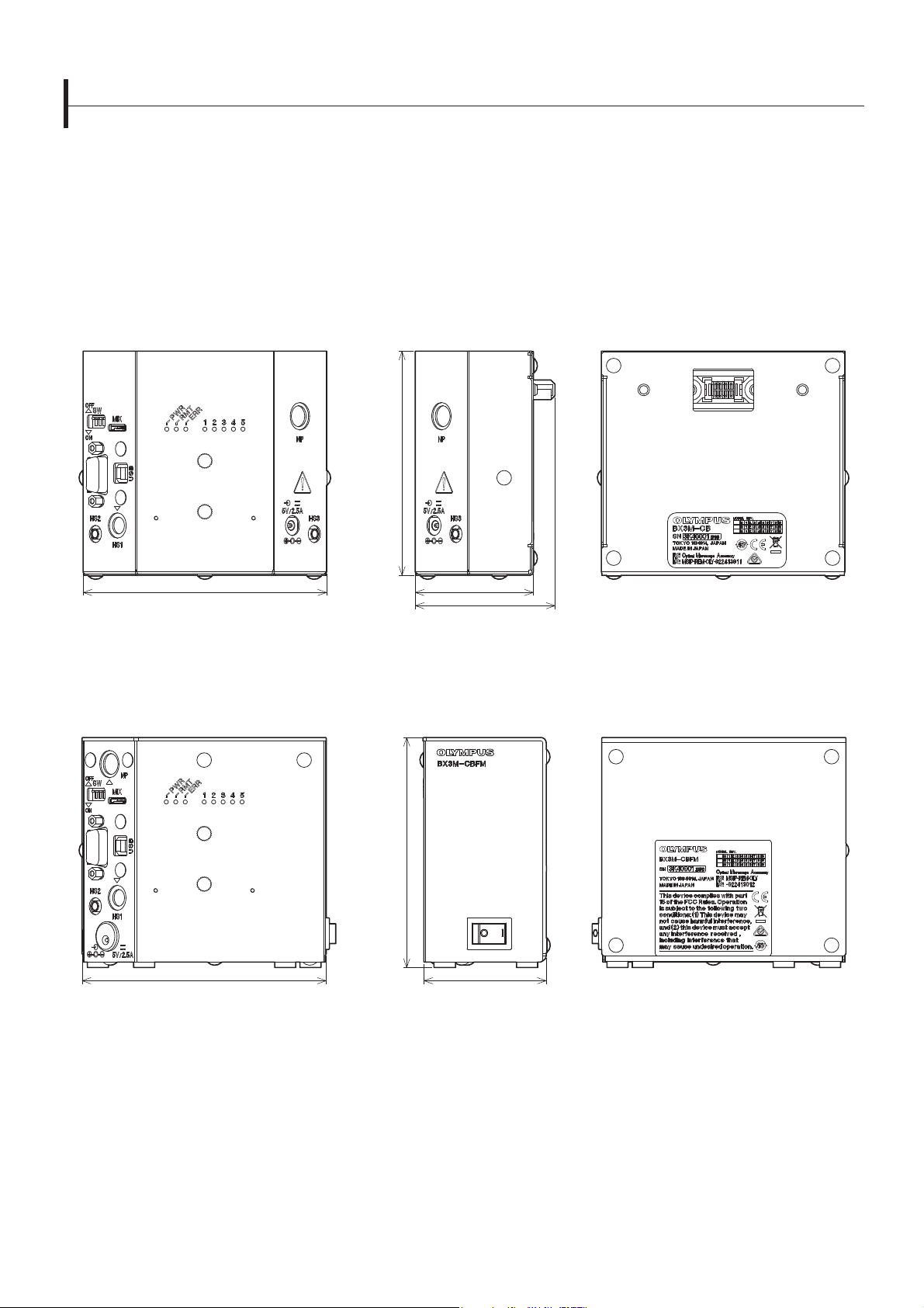
Motorized Units
Control Box for the BX53M/BXFM Microscope
BX3M-CB
Control Box for the BXFM Microscope
The control box can be connected to a PC using an RS232 or USB2.0 cable (attached to the microscope frame).
*Please consult your local Olympus representative for detailed system con guration and combination information.
105.8
115
55.8
66
BX3M-CBFM
Control Box for the BX53M Frame
The control box can be connected to a PC using an RS232 or USB2.0 cable (attached to the microscope frame).
*Please consult your local Olympus representative for detailed system con guration and combination information.
109.2
58.1116
Weight: 0.49 kg
Weight: 0.67 kg
13-1
Unit: mm
Page 93

Motorized Units
Motorized Universal Re ected Illminator for the BX2 Series
These various motorized units are used to help automate equipment.
BX-RLAA + U-D6REMC + U-LH100-3
Motorized BF/DF Re ected Light Illuminator + Motorized Nomarski DIC Sextuple Revolving Nosepiece + 100 W Halogen Lamp Housing
These components motorize the exchange of objectives, the selection of bright eld and dark eld observation, and the opening and closing of the
aperture diaphragm. The BX-UCB control unit has an RS232C connector, enabling control via a PC. For instructions on how to attach an illuminator,
please refer to the mounting directions for the BX-RLA2.
80
108
115
12
86.2
87
844045
41
(169)
11.8
(487)
400
64.8
81.5
Illuminator Cable Length: 1,800 mm Weight: 5.5 kg (excludes objectives)
107
211.5
BX-RFAA
Motorized Universal Re ected Light Illuminator
This re ected light uorescence illuminator enables users to simultaneously attach six mirror units and incorporates a motorized mirror unit changer
and shutter.
ø84
15
88
Unit: mm
9276
14
11.6 12
41
261
Illuminator Cable Length: 1.800 mm Weight: 4.3 kg
Revolving
Nosepiece
Mounting
Position
Illuminator
Mounting
Position
126
109.5
87.5
11.6 17
86.8 27.2
41
135
371
13-2
Page 94

Motorized Units
Motorized Units
These various motorized units are used to help automate equipment.
U-P5BDREMC
Motorized Centerable Quintuple BD Revolving Nosepiece with Slider Slot for DIC
U-D6BDREMC
Motorized Sextuple BD Revolving Nosepiece with Slider Slot for DIC
14
50
46
34
115.5
83.5
103.5
135
150 40.5
25.5
69.8
40
51.1
Weight: 80 g
U-D5BDREMC
Motorized Quintuple BD Revolving Nosepiece with Slider Slot for DIC
U-D6REMC
Motorized Sextuple Revolving Nosepiece with Slider Slot for DIC
U-P5REMC
Motorized Centerable Quintuple Revolving Nosepiece with Slider Slot for DIC
34
46
50
115
68.2
14
25.4
150
134
105
13-3
74
75
40.5
40
50.3
Unit: mm
Page 95

Motorized Units
Control Box for the BX2 Series
These various motorized units are used to help automate equipment.
BX-UCB
Control Unit
Motorized units, including the motorized illuminator and
auto focus unit, can be totally controlled from the BX-UCB.
212
216
125
* Extension cord U-RMT (1,700 mm) should be used to connect the lamp housing
(U-LH100-3) to the BX-UCB.
310
332
Depth
Weight: 1.0 kg
U-HSTR2
Hand Switch
105
108
146
Cable Length 2,000 mm Weight: 370 g
32
7
BX-REMCB
Control Box for Motorized Nosepiece and BF/DF Illuminator
The BX-RLAA and U-D5BDREMC/U-D6REMC/U-P5REMC can be
controlled from the U-HSTR2 or directly from the computer
keyboard via an RS232C connector.
*BX-RFAA and U-D5BDREM/U-D6REM combination is not applicable.
39.8
190.4
34
144
U-ACAD4515
AC Adaptor for BX-REMCB
+100
2000
0
711
129.51
351
Weight: kg Weight: kg
13-4
Unit: mm
Page 96

Motorized Units
Motorized Units for the BX2 Series
These various motorized units are used to help automate equipment.
U-AFA2M-VIS
Active Auto Focus Unit
This unit features a 785 nm auto focus laser light source. The multiple-spot sensor
enables fast, stable focusing on specimens with variable height differences.
*Class 1 laser product
108
313
62.5
45
51
*Consult your local Olympus dealer about the motorized focus.
Cable
AFA2M-CBL2M Weight: 0.23 kg Length: 2 m
AFA2M-CBL3M Weight: 0.36 kg Length: 3 m
U-FWR
Motorized Re ected Filter Wheel
With this lter wheel, quickly switch between 6 different lters.
180.5
147.9
Weight: 2.6 kg
130
42
30.5
2000
24.5
58.5
Weight: 1.0 kg
Unit: mm
13-5
Page 97

Motorized Units
Motorized Modular Microscope
With these components, users can integrate motorized microscope units into their equipment. Motorized operations, such as moving
the nosepiece up and down, changing objectives, opening and closing the aperture diaphragm, and changing between bright eld and
dark eld observation modes, are made possible using these components. Several of these operations can be totally controlled from an
external unit by adding an auto focus (AF) unit.
BXFMA-F
Motorized Illumination with Power Focus
This con guration combines the active auto focus unit (U-AFA2M-VIS), a single port tube with lens (U-TLU), a lamp housing, a
motorized nosepiece, and objectives.
77
206
310.5
5645169
133
5177
*Please consult your local Olympus representative for information about the mounting dimensions.
2367
92
334
342.1
Weight: 13 kg (BXFMA-F frame 7.6 kg)
U-FH U-IFFH
Focus Adjustment Knob Unit Focus Adjustment Knob Interface
32.5
70
33.6
75.5
5470 4
82.3
91.5
50
210
214
104
100
3
Weight: 1450 gWeight: 760 g
Unit: mm
13-6
Page 98

Motorized Units
Motorized Units for the BX3 Series
The exibility of the motorized uorescence illuminator accommodates multi color stained specimens. The 8-position mirror unit permits
quick changeover of uorescence colors.
BX3-RFAA
Motorized Fluorescence Illuminator
88
(180)
90
ø84
BX3-UCD8A U-D7REA
Motorized Universal Condenser Motorized Septuple Revolving Nosepiece with Slider Slot for DIC
The motorized universal condenser integrates a variety of optical
elements to accommodate transmitted light techniques including
bright eld, DIC, and phase contrast observation.
* Optical elements are required. Please consult your local Olympus
representative about optical elements combinations.
86.2 42.8
402.5
261
40
Weight: 4.2 kg
34
174.4
178
47
155.657
91.5
Weight: 1.6 kg Weight: 1.5 kg
50.8
84.4
96
142.1
72
42
13-7
ø121
40
44.4
Unit: mm
Page 99

Motorized Units
Control Box for the BX3 Series
The control box can be connected to a PC via the IEEE1394 cable.
210
214
BX3-CBH
Control Box for Fully-Motorized Function
100
280
288.8
Weight: 4.2 kg
U-CBM
Control Box M for Motorized Function
The control box can be connected to a PC via a RS232 cable.
*Please consult your local Olympus representative for a detailed system chart.
45
48
120185
125
Weight: 0.82 kg
U-CBS
Control Box for Coded Function
The control box can be connected to a PC via a RS232 cable (attached onto the microscope frame).
*Please consult your local Olympus representative for a detailed system chart.
163
117.5
30.5
16.5
37
Weight: 0.5 kg
Unit: mm
13-8
Page 100

Optical Terminology
1. FN and Practical Field of View
The field number (FN) is the size (in mm) of the eyepiece
diaphragm, which defines the viewable area of a specimen.
The diameter on the sample plane that can actually be viewed
through the eyepiece is known as the practical field of view
(FOV) and is determined by the following formula:
FOV =
Eyepiece FN
Objective Magnification
(mm)
2. Working Distance
The working distance (W.D.) is the distance between the front
edge of the objective and the specimen surface (or the
surface of the cover glass when using a cover glass objective)
when the specimen is in focus.
3. Parfocal Distance
The parfocal distance is the distance between the objective
mounting plane and the specimen. In UIS2/UIS objectives, the
parfocal distance is designed to be 45 mm.
5. Total Magni cation
Observation Through Eyepiece (binocular observation)
5.1
M(bino)=M(ob)×M(oc)
M(bino): Total magnification for binocular observation
M(ob): Objective magnification
M(oc): Eyepiece magnification
5.2 Video Monitor Observation
Total Magnification for Video Monitor
M(video monitor)= M(ob)×M(video camera adaptor)
×
Monitor Magnification*
M(video monitor): Total Magnification on the Video Monitor
M(ob): Objective Magnification
M(video camera adaptor): Projected magnification for video camera
adaptor including photo eyepiece
(refer to Figure 1)
*Refer to Figure 3 for "monitor magnification"
Practical Field of View for Video Monitor Observation
Practical Field of View for
Video Monitor Observation
Image Device Size *
=
M(ob)×M(video camera adaptor)
Working Distance and Parfocal Distance
W.D.
Objective
Mounting Position
Parfocal Distance
Focal Plane
For the parfocal distance of the LCPLFLN-LCD series
objectives, refer to the appropriate objective page.
4. Relationship Between the Objective's Focal Length
and Magni cation
The magnification indicated for a UIS2/UIS objective is the
value when the focal length of the tube lens is 180 mm.
Focal Length of Tube Lens
M(ob)=
M(ob): Objective magnification
f
f: Objective's focal length
M(ob): Objective Magnification
M(video camera adaptor): Projected magnification for video camera
adaptor including photo eyepiece
(refer to Figure 1 for projected magnifications)
*Refer to Figure 2 for image device size
Figure 1 Video Camera Adaptor and Projection Magnifications
Video Camera Adaptor (projection lens)
U-TV1X-1 +
Video Camera Mount Adaptors
U-TV1XC 1X
U-TV0.63XC 0.63X
U-TV0.5XC-3 0.5X
U-TV0.35XC-2 0.35X
U-TV0.25XC 0.25X
Figure 2 Imaging Device Size
Camera Format Diagonal Horizontal Vertical
1/3" 6.0 mm 4.8 mm 3.6 mm
1/2" 8.0 mm 6.4 mm 4.8 mm
2/3" 11.0 mm 8.8 mm 6.6 mm
The above table is for standard image device sizes.
Check your device size for precise calculation.
Figure 3 Imaging Device Size and Monitor Magnifications
Camera Format
1/3"
1/2"
2/3"
10" 15" 17" 19" 21"
42.3X 63.5X 72.0X 80.4X 88.9X
31.8X 47.6X 54.0X 60.3X 66.7X
23.1X 34.6X 39.3X 43.9X 48.5X
Example
What is the total magnifications for a video monitor when a
objective is 50X, a video camera adaptor U-TV0.5XC, a 2/3"
video camera, and a 21" monitor are used ?
Projection Magnification
1X
Monitor Size (diagonal)
14-1
 Loading...