

Page 1

INSTRUCTIONS
SUCTION PUMP
KV--5
CAUTION
Federal (USA) law restricts this device to sale
by or on the order of a physician.
0086
Page 2
IMPORTANT
Please read this manualcarefully before attempting to use the Olympus KV--5 suction pump as it contains important information on
the proper care, handling and use ofthe equipment. In addition, read the manuals of any other units (endoscope, light source, etc.)
that form part of the system.
The safety andperformance ofan endoscopic systemdepends notonly onthe endoscopebut also on the ancillary equipment used
with it. Ensure any ancillary equipment is compatible with the endoscope and other equipment used. These instructions should be
retained for reference during the life of the pr oduct. If you have any questions concerning the material contained in this manual,
please contact your Olympus representative or nearest Olympus office.
INTENDED USE
The Olympus KV-5 suction pump is a simple, r eliable pump intended for aspiration use during flexible endoscopy and general
medical or surgicalsuction. The c ompact sizeof the unit enablesit to be convenientlyused and stored onan endoscopy workstation.
It is intended for use within a health care facility, not for domiciliary or field and transport use.
The KV--5 is not designed for thoracic drainage.
Do not use the equipment for any purpose other than its intended use.
WARNING SYMBOLS USED ON DEVICE
Refer to instructions
SIGNAL WORDS
WARNING: D Indicates a potentially hazardous situation which, if not avoided, could result in death or serious injury.
CAUTION: D Indicates a potentially hazardous situation which, if not avoided, may result in minor or moderate injury. It may
also be used to alert against unsafe practices or potential equipment damage.
NOTE: D Indicates additional, helpful information.
Page 3

CONTENTS
PAGE
1 ST ANDARD SETS & FEATURES 1.........................................
2 OPERATING PRECAUTIONS 5............................................
3 INSTRUCTIONS FOR USE 6..............................................
4 CLEANING CARE AND STORAGE 11.......................................
5 MAINTENANCE AND REPAIR 12..........................................
6 SPECIFICATIONS 14...................................................
7 TECHNICAL DESCRIPTION 15............................................
8 ENVIRONMENTAL PROTECTION 16.......................................
Page 4

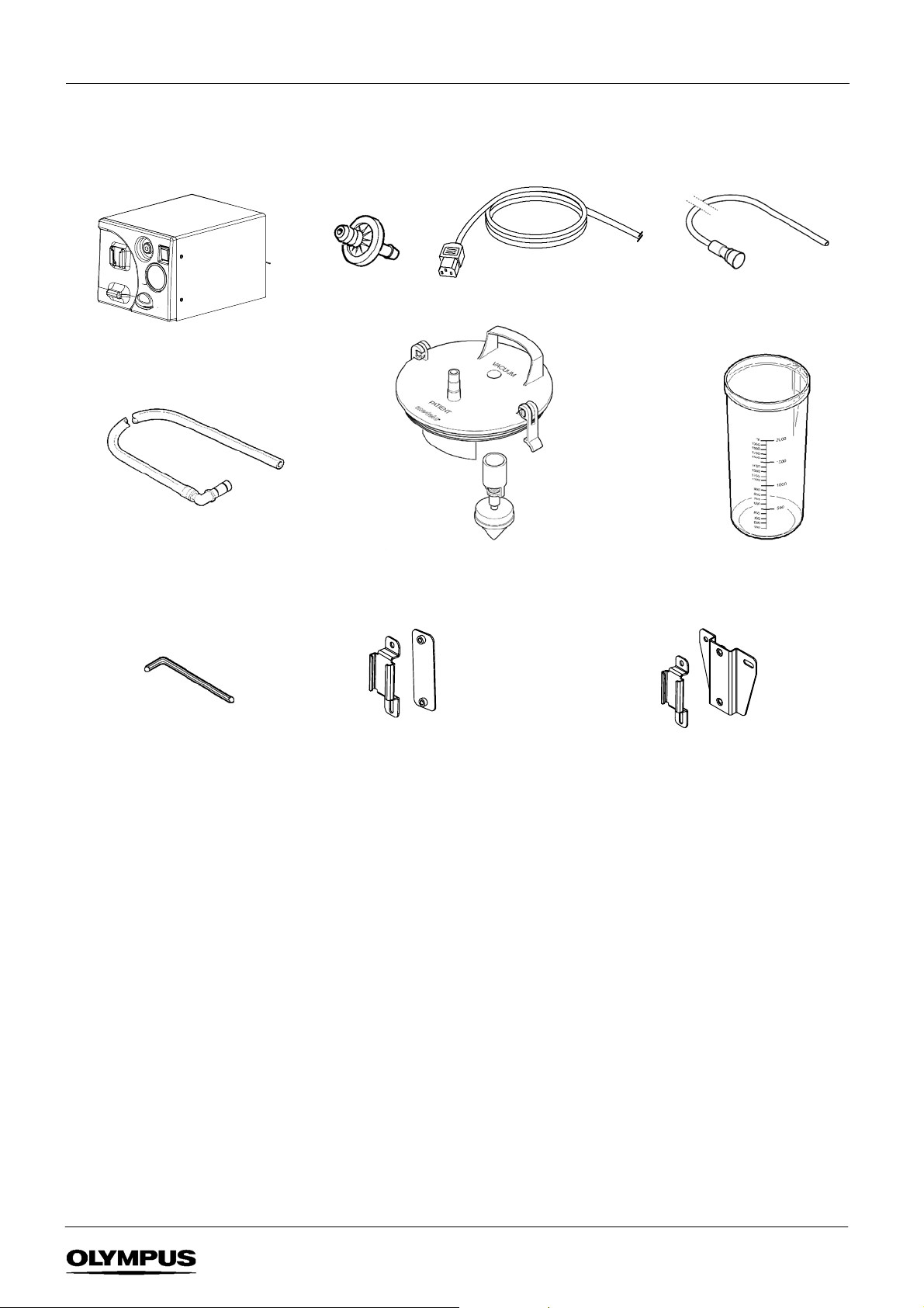
1 STANDARD SETS & FEATURES
The KV--5 is available in two configurations -- as a single--use suction system or a reusable suction system. Unpack the
equipment and confirm the items in the standard set ordered are present and undamaged. Retain the packaging for future use.
Contact Olympus if any parts are damaged or missing.
1.1 Standard set - Single- use suction system
KV-- 5 suction pump
Filter connecting tube 900mm
pk 10 (non --sterile)
K7503657
4mm A/F Allen key x1
Microbial F ilter
(pack of 10)
Lid for use with single--use liner*
K7503761
Suction jar mounting kit for
Olympus WM--30/60
K7503555
Supplied with standard sets:
p/no 2000455, 2000456
Power
cable
Single--use liner 2 ltr pk 25
K7503430
or
Suction jar mounting kit for
Olympus WM--N60/D60, Olympus TC-- C1/NE
K7503556
Supplied with standard sets:
p/no 2000450, 2000451
Patient connecting tube 2m
pk 5 (
sterile)
Suctionjar2ltr
K7503763
1
SUCTION PUMP KV--5
Page 5
1.2 Standard set - Reusable suction system
KV-- 5 suction pump
Filter connecting tube 900mm
pk 10 (non --sterile)
K7503657
Microbial F ilter
(pack of 10)
Power
cable
Lid with float mechanism*
K7503760
Patient connecting tube 2m
pk 5 (
sterile)
Suctionjar2ltr
K7503763
4mm A/F Allen key x1
Suction jar mounting kit for
Olympus WM--30/60
K7503555
Supplied with standard sets:
p/no 2000455, 2000456
or
Suction jar mounting kit for
Olympus WM--N60/D60, Olympus TC-- C1/NE
K7503556
Supplied with standard sets:
p/no 2000450, 2000451
SUCTION PUMP KV--5
2
Page 6
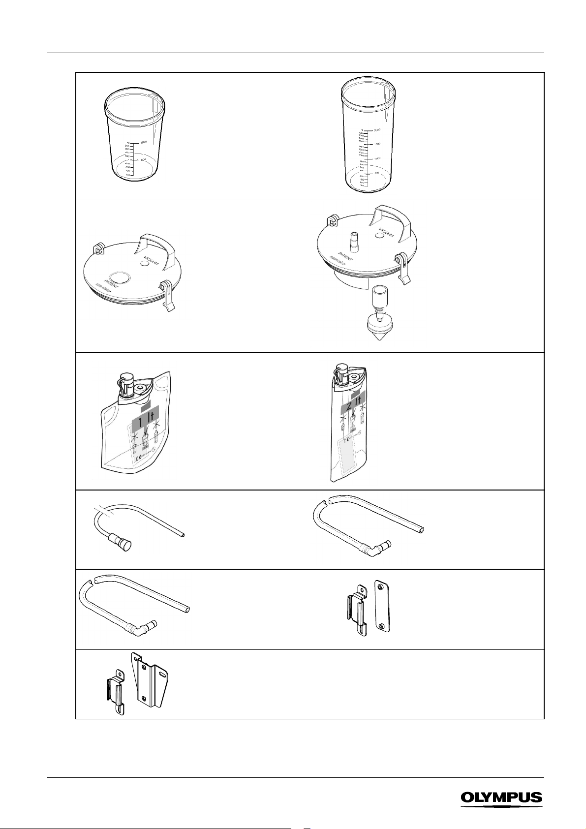
1.3 Replacement / Optional parts
Suctionjar1ltr
K7503762
Lid for use with single--use liner*
K7503761
Single--use liner 1 ltr
pk 30
K7503428
Suctionjar2ltr
K7503763
Lid with float mechanism*
K7503760
Single--use liner 2 ltr
pk 25
K7503430
Patient connecting tube 2m
pk 50 (sterile)
K7503432 (Rest of World)
K7505595 (Americas only)
Filter connecting tube 900mm
pk 10 (non --sterile)
K7503657
For use with trolley mounted
suction jar
Suction jar mounting kit for
Olympus WM--N60/D60
Olympus TC--C1/NE
K7503556
*Thesuctionjarlidcanbeusedwithboth1and2litresuctionjars.
Filter connecting tube 340mm
pk 10 (non --sterile)
K7503486
For use with1 litre KV--5
mounted suction jar
Suction jar mounting kit for
Olympus WM--30/60
K7503555
3
SUCTION PUMP KV--5
Page 7

1.4 Features
Label 5
Single--use
suction liner
Filter
connecting tube
Suction jar and lid
Rear panel
Microbial filter
Power switch
Label 1
Label 2
V acuum gauge
(for indication only)
Label 3
V acuum
regulator
Label 6
FIGURE 1-1
Label 4
Potential
equalisation
terminal
1.5 Labels
Label 1 CHANGE FIL TER DAILY OR WHEN
Label 3 MAXIMUM LEVEL OF VACUUM 85kPa
Label 5 CAUTION: REMOVE TRANSIT SCREWS
IEC power receptacle
(with integral fuses)
Exhaust outlet
Label 2 SUCTION
CONT AMI NATED
Label 4 RATING PLATE
HIGH VACUUM / HIGH FLOW
Label 6 CAUTION: REMOVE TRANSIT SCREWS
FROM BASE BEFORE USE. REPLACE
BEFORE TRANSPORTA TI O N.
BEFORE USE. REPLACE BEFORE
TRANSPORTATION.
NOTE
Label 5 should be removed and stored safely when the transit screws have been removed (Section 2.1). When
the unit is to be transported, replace the transit screws and affix the label on top of the unit.
Label 6 is permanent.
SUCTION PUMP KV--5
4
Page 8

2 OPERATING PRECAUTIONS
2.1 Before use
D The unit must be used solely for its designed purpose, that is endoscopic aspiration and general medical or surgical
suction in a health care facility. This device is a ‘high vacuum, high flow’ device and is not intended for thoracic
drainage.
D Explosion hazard -- never install or use the KV--5 within the zone of risk of flammable gases.
D The unit is fitted with two M6 transit screws to protect the pump during transportation. Before use, remove both
screws with fibre washers using the 4mm A/F Allen key provided (Figure 2-1), then remove the label from the top of
the unit. Store these items safely as they must be refitted when transporting the unit.
FIGURE 2-1
CAUTION: REMOVE TRANSIT
SCREWS BEFORE USE. REPLACE
BEFORE TRANSPORTATION.
D Excessive frothing in the suction jar during use may inhibit oper ation of the fluid cut--off mechanism -- use a
proprietary anti--foam agent as necessary to minimise frothing.
D The electrical installation of the room where the unit is to be used must comply with local or national regulations.
D The KV-5 is not intended to be used when positioned on inclined surfaces as the suction jar fluid cut--off mechanism
may not function correctly.
D The unit is only to be used by suitably qualified personnel in accordance with these instructions.
D Replace the microbial filter daily or when contaminated.
D Do not use anti-static tubing to connect the endoscope to the suction pump as patient safety may be compromised.
D The suction jar must never be used ‘free standing’ on the workstation or any surface. The 1 litre suction jar simply
slides into the bracket pr ovided on the front panel of the unit as shown on page 2, the 2 litre suction jar should be
secured to workstation using the suction jar bracket.
D Periodically inspect the suction jar for obvious signs of wear/damage and replace if necessary.
D If the suction jar is dropped, it must be thoroughly inspected to ensure there are no cracks and tested to ensure the
lid is sealing correctly. If damage or a leak is evident, discard the suction jar and replace.
D When a suction jar is attached to a workstation using the optional suction jar bracket, remove the suction jar before
manoeuvring the workstation.
5
SUCTION PUMP KV--5
Page 9

D Ensure the exhaust at the rear of the unit is unobstructed when the unit is operational.
D Store and use the KV--5 within the environmental conditions described in Section 6; failure to do so may lead to
equipment malfunction or failure.
D Only use replacement parts and accessories as specified in Section 5.3. Failure to do so may lead to equipment
malfunction or failure.
2.2 During use
D Do NOT lift the suction jar by the lid, always grip with two hands on either side of the suction jar, otherwise the cap
and jar may become separated and spillage of its contents may result.
D If aspirated material has been drawn past the microbial filter and into the pump, the unit must be removed from use
and returned to Olympus for service.
D To prevent liquid backflow within the patient connecting tube, always leave the unit running until the patient tube is
disconnected from the suction jar.
2.3 After use
D If single use suction liners are not being used, the suction jar will contain potentially infectious body fluids. Take
suitable precautions, as dictated by local hospital policy, such as use of personal protective equipment, and empty
into a suitable waste disposal system, together with an appropriate quantity of water to dilute the jar contents.
D Single use suction liners, used filters and suction tubing will contain potentially infectious material. Dispose of
carefully as dictated by local hospital policy as clinical waste for incineration.
D Always empty the suction jar before moving the equipment. Care should be taken to obtain a firm grip underneath
the body of the equipment before moving. The suction jar holder must never be used as a hand hold or carrying
handle.
3 INSTRUCTIONS FOR USE
3.1 Place the KV--5 on a level flat surface.
3.2 Thoroughly inspect the suction jar for cracks or signs of damage and any suction tubing to be used for signs of wear or
damage. Do not use if damage is noted.
WARNING
Defects in the suction jar may cause the jar to implode when under vacuum.
NOTE
The suction jar may be used with or without single--use suction liners. Use without requires an optional suction
jar lid with integral float mechanism (p/no K7503760).
3.3 Use with single- use suction liners
NOTE
The standard set supplied is a 2 litre suction system. If a 1 litre system is required, a 1 litre suction jar, a 1 litre
single--use suction liner and 340mm filter connecting tube will be required. These items are optional and are
detailed in Section 1.3.
(1) Refer to the instructions supplied with the single use suction liner and fit the liner to the suction jar.
NOTE
The single--use liners incorporate a solidifier to aid disposal.
SUCTION PUMP KV--5
6
Page 10

(2) Referring to Figure 3-1, locate the suction jar into the suction jar holder located on the front panel of the unit.
NOTE
The suction jar holder will only accommodate the 1 litre suction jar. 2 litre suction jars should be mounted on
the workstation and require the use of a suction jar mounting bracket (see Section 1). Fitting instructions for the
suction jar mounting brackets are provided with the brackets.
FIGURE 3-1
1 litre suction jar
Suction jar holder
(3) Remove the transit bung from the filter housing (retain for transportation) on the front of the unit and insert the
microbial filter with the word ‘Olympus’ facing outermost (see Figure 3-2)
FIGURE 3-2
Filter housing
Microbial filter
Filter connecting tube
Microbial filter
Filter connecting tube 90 ˚ connector
(4) Connect the patient tube between the suction jar lid (Figure 3-3) and endoscope or other equipment as required.
FIGURE 3-3
Patient connecting tube
(5) Push the open end of the filter connecting tube onto the microbial filter and fully insert the 90˚ connector into the
suction jar lid marked VACUUM (Figure 3-4).
7
SUCTION PUMP KV--5
Page 11

FIGURE 3-4
Filter connecting tube
Microbial filter
Filter connecting tube 90 ˚ connector
(6) Ensure the KV--5 power switch is OFF and the vacuum regulator is set to ‘MIN’, then connect the power cable into
the IEC receptacle on the rear of the unit and a suitably grounded AC wall outlet or isolation transformer socket.
(7) Set the power switch to the ‘l’ position, the switch will illuminate and the pump will start to run.
(8) The suction level can be increased and set as required by turning the vacuum regulator in a clockwise direction. To
obtain suction via an endoscope, refer to the instructions for the endoscope.
(9) Suction should be stopped when the fluid reaches the 1 litre / 2 litre mark.
NOTE
If the liner is overfilled, an integral hydrophobic filter will prevent further suction. To allow suction to continue,
proceed as below.
(10) Change the liner as follows:
CAUTION
The single--use suction liner, filters and suction tubing will contain potentially infectious body fluids. Take
suitable precautions, as dictated by local hospital policy, such as use of personal protective equipment, and
dispose of carefully as clinical waste for incineration.
Do NOT lift the suction jar by the lid, otherwise the lid and jar may become separated and spillage of its
contents may result.
When using single--use liners, if the liner is over filled or filled rapidly and the KV--5 is switched OFF with the
patient tube disconnected from the endoscope, aspirated fluid may syphon from the single use suction liner into
the patient connecting tube. Always leave the unit running until the patient connecting tube is disconnected
from the suction jar to prevent liquid back flow..
The patient tube may contain residual fluid so carry holding both ends of the tube upright, taking care to ensure
it is properly drained before disposal in line with local hospital policy.
a) Keep the KV--5 switched ON and disconnect the patient connecting tube from the single use suction liner.
b) Replace the cap on the single use suction liner and press the cap firmly downwards, through the lid into the
suction jar. The contents of the liner are now sealed.
FIGURE 3-5
c) Switch OFF the KV--5, remove the filter connecting tube if required and then remove the suction jar lid. Finally,
remove the single use suction liner from the suction jar and dispose of in line with local hospital policy.
SUCTION PUMP KV--5
8
Page 12

3.4 Use with reusable suction system
NOTE
The standard set supplied is a 2 litre suction system. If a 1 litre system is required, a 1 litre suction jar and a
340mm filter connecting tube will be required. These items are optional and are detailed in Section 1.3.
(1) Push the float fully onto the vacuum spigot inside the lid (see Figure 3-6).
(2) Position the suction jar lid with float mechanism onto the jar with the word PATIENT on the lid facing the front of the
jar, then press the lid down firmly and secure the two fasteners, see Figure 3-6.
Suction jar lid with float
FIGURE 3-6
(3) Referring to Figure 3-7, locate the suction jar into the suction jar holder located on the front panel of the unit.
NOTE
The suction jar holder will only accommodate the 1 litre suction jar. 2 litre suction jars should be mounted on
the workstation and require the use of a suction jar mounting bracket (see Section 1). Fitting instructions for the
suction jar mounting brackets are provided with the brackets.
FIGURE 3-7
1 litre suction jar
Suction jar holder
(4) Remove the transit bung from the filter housing on the front of the unit and insert the microbial filter with the word
“Olympus” facing outermost (see Figure 3-2)
FIGURE 3-8
Filter housing
Microbial filter
(5) Connect the patient tube between the suction jar lid (Figure 3-9) and endoscope or other equipment as required.
9
SUCTION PUMP KV--5
Page 13

FIGURE 3-9
Patient connecting tube
(6) Push the open end of the filter connecting tube onto the microbial filter and fully insert the 90˚ connector into the
suction jar lid marked VACUUM (Figure 3-10).
FIGURE 3-10
Filter connecting tube
Microbial filter
Filter connecting tube 90 ˚ connector
(7) Ensure the KV--5 power switch is set to O and the vacuum regulator set to ‘MIN’, then connect the power cable into
the IEC receptacle on the rear of the unit and a suitably grounded AC wall outlet or isolation transformer socket.
(8) Set the power switch to the ‘l’ position, the switch will illuminate and the pump will start to run.
(9) The suction level can be increased and set as required by turning the vacuum regulator in a clockwise direction. To
obtain suction via an endoscope, refer to the instructions for the endoscope.
(10) Suction should be stopped when the fluid reaches the 1 litre / 2 litre mark.
NOTE
When the fluid in the suction jar reaches the float, the float will rise and seal the patient tube when capacity is
reached, preventing further suction. Empty the suction jar replace the lid to allow suction to continue.
(11) Empty the suction jar as follows:
CAUTION
The suction jar, filters and suction tubing will contain potentially infectious body fluids. Take suitable
precautions, as dictated by local hospital policy, such as use of personal protective equipment, and dispose of
carefully as clinical waste for incineration.
Do NOT lift the suction jar by the lid, otherwise the lid and jar may become separated and spillage of its
contents may result.
The patient tube may contain residual fluid so carry holding both ends of the tube upright, taking care to ensure
it is properly drained before disposal in line with local hospital policy.
a) Keep the KV--5 switched ON and disconnect the patient connecting tube from the suction jar lid.
b) Turn off the unit and remove the filter tube from the suction jar lid.
SUCTION PUMP KV--5
10
Page 14

c) Taking suitable precautions, as dictated by local hospital policy, such as use of personal protective equipment,
empty the jar into a s uitable waste disposal system, together with an appropriate quantity of water to dilute the
jar contents.
d) Clean the suction jar and lid as described in Section 4 before re--use.
4 CLE ANING CARE AND STORAGE
4.1 Remove the filter connecting tube and clean using neutral detergent and water. The tube may be sterilised by autoclaving
(upto137˚C max) after removing the 90˚connector, which should bereplaced.The microbial filter should bereplaced daily
or when contaminated. Replace the patient connecting tube when contaminated or at the end of each patient list.
CAUTION
The patient tube is not autoclavable.
4.2 Following use, remove the lid from the jar by disconnecting the lid clips and where applicable remove the float assembly.
Clean thoroughly using a soft brush and mild detergent solution. The suction jar cap may be sterilised by autoclaving up
to 137˚C max according to hospital policy, then reassembled for further use.
CAUTION
Do not use phenol-- or chlorine--based disinfectants to decontaminate the suction jar lid as damage and rapid
deterioration of these components will result.
4.3 The suction jar may be sterilised by autoclaving up to 137˚C max according to hospital policy, or disinfected by cold fluid
immersion.
CAUTION
Do not use phenol or chlorine based disinfectants to clean the suction jar as damage to the jar may result.
Do not place alcohol or aldehyde-based detergents, antiseptics or antifoam agents in the suction jar prior to
use, as any vapour released may damage the hydrophobic filter. This may result in fluid ingress to the vacuum
pump, which will then need to be serviced or replaced.
Do not stack suction jars when autoclaving as damage to the jar may result.
Contact with non-ionic detergents, such as those found in thermo-chemical disinfection can cause cracking of
the suction jar.
Ensure the suction jar is thoroughly rinsed with fresh water following disinfection.
4.4 Clean the KV-5 casing, including the microbial filter housing, by wiping with a cloth dampened with detergent and water or
alcohol impregnated swab. Thoroughly rinse off any detergent using a soft cloth dampened with clean water.
4.5 Before storing the KV-5, ensure the unit has been thoroughly cleaned and its accessories have been sterilised or
disinfected. Do not leave a single use liner in the suction jar.
11
CAUTION
Do not store single use liners in damp or wet conditions as damage to the hydrophobic filter will result and the
liners will be unusable
SUCTION PUMP KV--5
Page 15

4.6 If the KV-5 is to be transported, ensure that:
(1) The unit is thoroughly cleaned.
(2) The filter is removed and the transit bung fitted.
(3) The two transit screws with fibre washers are replaced and tightened using the 4mm A/F Allen key.
(4) The label (label 5) is affixed to the top of the unit.
(5) The unit is packed in its transit packing.
CAUTION
Failure to fit the transport screws when transporting the unit may result in damage to the pump.
5 MAINTENANCE AND REPAIR
There are nooperator--serviceablecomponentsinsidethe KV--5.Refer servicing to qualifiedservice personnel. IfrepairoftheKV-5
is required, contact Olympus.
Olympus will not be liable for any incident resulting from repair, adjustment or modification carried out by other than personnel
authorised by Olympus.
5.1 Preventive Maintenance
Daily - by user
D Check that the filter connecting tube, suction jar and lid are in good condition.
D Replace the microbial filter and or filter connecting tube (with 90˚ connector) if contaminated.
D Clean (and disinfect/sterilise if required by local policy) the suction jar, suction jar lid and filter connecting tube.
Weekly - by user:
D Clean the unit’s casework, ensuring the exhaust at the rear of the unit is clear.
D Inspect the suction jar for cracks or signs of wear, replace if necessary.
D Check the maximum v acuum available by sealing the patient connection of the suction jar lid. This should be at least
85 kPa.
Six-monthly - by qualified hospital engineer or Olympus agent:
D Check internal condition of unit, wiring security, etc.
D Check the flow rate by timing how long it takes to reach 60 kpa with a 2 litre suction jar connected -- should be
approximately 10 seconds. Contact Olympus if less than this for the pump to be serviced.
A maintenance & repair manual is available from Olympus, part number 5070225.
SUCTION PUMP KV--5
12
Page 16

5.2 Troubleshooting
haveoperated.Checktheventsareclear.Whenthetemperature
fasp
NOTE:
Ifaspiratedfluidorsolidmaterialhasbeendrawnintoth
e
Symptom Possible cause
Pump fails to operate Check that the unit is corr ectly connected to the power supply
and that the power switch illuminates when set to l.
Check the fuses, located within the pull-out fuseholder above the
power plug connector
NOTE: Always replace a fuse with one of the correct type and
rating. If a fuse continues to blow, contact Olympus.
The thermal cut-out within the windings of the pump motor may
have operated. Check the vents are clear. When the temperature
of the windings falls to an acceptable level normal operation will
resume. If the problem r ecurs, contact Olympus.
Pump operates but no suction or suction level is too low. Check that all connections are secured.
Check the unit is correctly connected to the endoscope or other
device.
Check that the microbial filter is not blocked and suction tubes
are correctly positioned and are not kinked, blocked or punctured.
Check the jar liner is not full and that the float mechanism (if
used) is not stuck in the closed position.
Check performance of the pump as per Section 5.1.
Check the vacuum regulator is set to the correct position.
Check all connections and tubing for air leakage.
NOTE: I
unit, the pump will continue to operate, but the unit should be
returned to Olympus for inspection and repair.
iratedfluid or solid material has been drawn into the
5.3 Replacement parts & accessories
Fuse T1.25H (20mm) 220--240V units 7146299......................
Fuse T2.5H (20mm) 100--120V units 7146302.......................
Microbial filter (pack of 10) 7048271...............................
Power cable 230V (UK) 7145454.................................
Power cable 230V (Europe) 7145462..............................
Power cable 110V (USA) 7146311................................
Power cable 100V (Japan) 7146329...............................
Suction jar 1ltr K7503762.......................................
Suction jar 2ltr K7503763.......................................
Lid for single--use liner K7503761..................................
Lid with float mechanism K7503760................................
Single--use liner 1ltr pk 30 K7503428...............................
Single--use liner 2ltr pk 25 K7503430...............................
Patient connecting tube 2m pk 50 (Rest of World) K7503432..............
Patient connecting tube 2m pk 50 (Americas only) K7505595..............
Filter connecting tube 340mm pk 10 K7503486........................
Filter connecting tube 900mm pk 10 K7503657........................
Jar mounting kit Olympus WM--30/60 K7503555.......................
Jar mounting kit Olympus WM--D60/N60, TC range K7503556.............
Transit screw K3921028........................................
Fibre washer K3921029........................................
13
SUCTION PUMP KV--5
Page 17

6 SPECIFICATIONS
y
Regulator
y
/EE
Crelati
d
ical
devi
C
l
I
Ia.T
h
Dimensionsand
Power
condition
s
Items Specifications
Product name Olympus Suction Pump KV--5
Classification
(electromedical
equipment)
Standards
compliance
Electro-magnetic
compatibility
Type of protection
against electrical
shock
Degree of protection
against electrical
shock
Degree of protection
against explosion
Mode of operation Continuous
Complies with EN ISO 10079--1 and EN IEC 60601--1 (220--240V model), UL 2601--1 and
Certified to CAN/CSA Std. No. C22.2 No. 601.1--M90 (100-120V model).
This product complies with the requirements of EN IEC 60601-1-2 for emissions and
immunity, and as such, its operation is unlikely to be affected by , or cause interference
with, equipment meeting appropriate EMC standards. As a precaution, equipment which
may be sensitive to interference outside the limits specified by EN IEC 60601--1--2 should
not be placed in close proximity t o the KV--5.
Classification according to EN IEC 60601-1 / UL 2601--1:
Class I with Type BF applied part.
In accordance with EN IEC 60601-1 and UL 2601--1, the KV--5 is marked with the
symbol to indicate the provision of an adequate degree of protection against electrical
shock and that it has an applied part isolated from all other parts of the equipment.
None: the Olympus KV--5 must NOT be used in the zone of risk of flammable anaesthetic
gases.
Regulator
status
European Economic
Area (EEA)
End of life
Dimensions and
weight
Power switch Marking The power switch is marked: l - on, O -off.
Power
requirements
Environmental
Fluid ingress
Resistance to
chemicals
Pump
specification
Thermal cut-out
Dimensions Height: 220 mm Width: 255 mm Depth: 310 mm
Weight 12.7 kg
Power supply Frequency Fusing Power rating
220-240V~ 50/60Hz 2 x T1.25H 130V A
100-120V~ 50/60Hz 2 x T2.5H 130V A
Marking: The mark ~ on the product indicates the requirement for an AC power supply.
Ambient
temperature
Relative humidity Maximum: 95% at 40˚C relative non-condensing
Atmospheric
pressure
In accordance with EN IEC 60601-1/UL 2601--1, the product is marked IPX1 to indicate that it is provided with an
enclosure that prevents entry of such an amount of falling liquid as might interfere with its safe and satisfactory
operation when correctly positioned.
The external surfaces of the Olympus KV--5 are resistant to: 2% aqueous neutral detergent, 70% ethyl alcohol,
isopropyl alcohol, water.
Nominal vacuum: 85 kPa ±10%
Minimum free air flow rate: 20 l/min
In accordance with ISO 10079-1, the unit is marked with the words ‘HIGH VACUUM, HIGH FLOW’ to indicate it
attains a vacuum of at least 60 kPa in 10 seconds and a free air flow rate of 20 l/min or greater.
A thermal cut-out is contained within the windings of the pump motor, set to operate if the temperature of the
windings exceeds 125˚C (257˚F).
This mark on the product (220-240V model) indicates compliance with Directive
93/42
0086
given in the first two digits of the serial number.
In accordance with European Directive 2002/96/EC on Waste Electrical and
Electronic Equipment, this symbol indicates that the product must not be
disposed of as unsorted municipal waste, but should be collected separately.
Refer to your local Olympus distributor for return and/or collection systems
available in your country.
Operational: +10˚Cto+40˚C(+50˚F to +104˚F)
Storage: -40˚Cto+70˚C (-40˚F to +158˚F)
Operational: 70 to 106 kPa
Storage: 23.5 to 106 kPa
ng to me
ces,
ass
e year ofmanufactureis
SUCTION PUMP KV--5
14
Page 18

Single--use
suction liner
Suction jar
Suction jar lid
Suction tubing
V acuum gauge Range: 0 to 100 kPa Accuracy: better than±2.5% of full scale
Olympus is continually developing its product range and reserves the right to alter the above specification without notice. The
Olympus KV--5 is manufactured in the UK by KeyMed (Medical & Industrial Equipment) Ltd.
To prevent fluid from being drawn up to the pump, the single--use suction liners, available in 1 or 2 litre versions,
contain a mechanism to shut off the flow when the liner is overfilled. This mechanism is activated when contact
is made with aspirated fluid. The single--use liners also contain a solidifier to aid safe disposal.
The 1 and 2 litre suction jars are manufactured from polysulfone, allowing them to be autoclaved up to 137˚C
max. The suction jar is impact resistant.
The suction jar lid clips and where applicable the float mechanism, are autoclavable up to 137˚C max. The inlet
connection (from the endoscope) is marked with the word PATIENT, the outlet connection (to the filter) is marked
with the word VACUUM. An optional lid is available having an integral float mechanism for use without
single--use suction liners.
The filter tubing supplied is silicone rubber, 6.0mm internal diameter, 12.0mm external diameter. The sterile
patient tubing supplied is PVC, 7.0mm internal diameter, 10.0mm external diameter. Use only tubing with the
specified dimensions, otherwise equipment malfunction may result.
The patient tube connects to a barbed connector on the suction jar cap and the filter tube has a removable 90˚
connector which is a push--fit into the suction jar cap.
7 TECHNICAL DESCRIPTION
7.1 Mechanical Operation
RefertoFigure7-1
The pump used in the KV-5 is a piston unit. The pump is connected to the suction jar by silicone tubing and has an
in-line microbial filter. A suction tube connects the endoscope or other devices to the suction jar. When the KV-5 is
switched on, a vacuum is created in the suction jar, which results in suction through the endoscope when the
appropriate endoscope control is operated, or through other devices. The vacuum level is controlled by a regulator
located on the front panel to which a vacuum gauge is connected. Air is drawn through the pump and is then exhausted
to atmosphere, passing through the exhaust at the rear of the unit.
7.2 Electrical Operation
RefertoFigure7-2
Power is provided to the unit from the AC power supply by the power supply lead.
The power socket at the rear of the unit has an integral fuseholder through which power is supplied to the power switch.
When the power switch is switched to the ‘l’ position, power is supplied to the motor, enabling the pump to operate.
Technical information regarding this product is available on request to assist suitably qualified personnel with repairs.
Contact Olympus regarding this information.
15
SUCTION PUMP KV--5
Page 19

Endoscope umbilical connector
(or other applied part)
Microbial filter
FIGURE 7-1
Suction jar
Single use
suction liner
Patient tube
Brown
Filter tube
Vacuum gauge
Power socket
Fuseholder
LNE
Blue
Green/Yellow
Black
Red
Vacuum pump
Exhaust
Exhaust silencer
Vacuum regulator
FIGURE 7-2
Vacuum pump
L5 N1 N2 L4
Illuminated
power switch
8 ENVIRONMENTAL PROTECTION
There are no known risks associated with disposal of the KV--5 at the end of its working life. If however, aspirated fluid
has entered the pump, it may be contaminated with infectious material and should therefore be disposed of in
accordance with local regulations or policy.
SUCTION PUMP KV--5
16
Page 20

OLYMPUS MEDICAL SYSTEMS CORP.
2951 Ishikawa-cho, Hachioji-shi, Tokyo 192-8507, Japan
Fax: (0426) 46-2429 Telephone: (0426) 42-2111
OLYMPUS MEDICAL SYSTEMS EUROPA GMBH
(Premises/Goods delivery) Wendenstrasse 14-18, D-20097 Hamburg, Germany
(Letters) Postfach 10 49 08, D-20034 Hamburg, Germany Telephone: (040) 237730
OLYMPUS AMERICA INC.
3500 Corporate Parkway, P.O. Box 610 Center Valley, PA 18034-0610, U.S.A.
Fax: (484) 896-7128 Telephone: (484) 896-5000
OLYMPUS SURGICAL & INDUSTRIAL AMERICA INC.
One Corporate Drive, Orangeburg, N.Y. 10962, U.S.A.
Fax: (845) 398-9444 Telephone: (845) 398-9400
KEYMED LTD.
KeyMed House, Stock Road, Southend-on-Sea, Essex SS2 5QH, United Kingdom
Fax: (01702) 465677 Telephone: (01702) 616333
OLYMPUS SINGAPORE PTE LTD.
491B, River Valley Road #12-01/04, Valley Point Office Tower, Singapore 248373
Fax: 6834-2438 Telephone: 6834-0010
OLYMPUS (BEIJING) SALES & SERVICE CO,. LTD.
No.6 GongYuanXijie, Jian Guo Men Nei, DongCheng District, Beijing, 100005, China
Room 1406 E Tower, GongYuan No. 6 Royal Palace,
Fax: (10) 6518-0865 Telephone: (10) 6518-8080
OLYMPUS MOSCOW LIMITED LIABILITY COMPANY
117071, Moscow, Malaya Kaluzhskaya 19, bld. 1, fl.2, Russia
Fax: (095) 958-2277 Telephone: (095) 958-2245
Issue
7
J
anuary 2008
OLYMPUS AUSTRALIA PTY. LTD.
31 Gilby Road, Mount Waverley, Victoria 3149, Australia
Fax: (03) 9543-1350 Telephone: (03) 9265-5400
OLYMPUS LATIN AMERICA INC.
6100 Blue Lagoon Drive, Suite 390 Miami, FL 33126-2087, U.S.A.
Fax: (305) 261-4421 Telephone: (305) 266-2332
OLYMPUS KOREA CO,. LTD.
8F, Hyundai Marines Bldg., 646-1 Yeoksam-Dong, Kangnam-Gu, Seoul 135-080 Korea
Fax: (02) 6255-3499 Telephone: (02) 1544-3200
EKeyMed 2008
PrintedinUK
KT5070196/108
 Loading...