

Page 1
Dark-field
Zoom
Stereo
Microscope
I
NS
TRUC
TI
ON
MANUAL
Model
OLYMPUS
Page 2
T
ABLE
OF
CONTENTS
Page
I . Standard Set ····..···· ················..···························1
D. Specifications ···..·1
ill. Nomenclatures of Main
compcnents-
··· ·..········2
IV
.
Op
tical System · ·3
V. Structure
-4
\1. Assembly ···· ·..· · ·6
'I . Operation ···..······· ..····7
'ID
. Optical Characteristics 9
Page 3
I • STANDARD SET
Mic
roscope
(Main Body w
ith
Bino
cular
Head) ················································ 1
set
Stage (Wit h Bright/ Dark Field
Illumi
nat
or, P
ower
Sou-se and
Arm)············
···1
set
E
yepie
ces
(GIOX
and
G20X)
··················1paireach
Sp
ec
imen Holder
·······
················
················
1 s
et
Epi Illumi
nat
or (LSG- D) ·················
··········1set
Iris Dia
phr
agm (Slip ontype) ··················1 pc.
St age Glass pl at es (clear and
frosted
) ···········..·..·..·..···· ························..·····1 pc. each
E
yepie
ce Caps ········································ ··2 DCS .
Eye-shades (for G eyepieces) ··················2 pcs.
Spare Light Bulbs
20W
2 pes.
6V
12W 2 pcs.
Wooden Case···································································································1
set
Dust Cover ···· ···
···············
·····
·····················
1 pc.
Inspection
Cert
ifi
cate
·······················································································1 copy
Inst ruc
tio
n Book _ ·
········
························_·····1 copy
II. SPECIFICATIONS
1. Zoomi ng Mechan ism : Zoom Ra
ti
o 5.7 (vertatlonso.zx-c
-a
x)
2. Total Magnifications :
Wit
h GI 0XEyepiece :
7X-
40X
With
G20XEyep iece :
14X_80X
3. Inctined Binocular Head :
Inclinat ion :
45°
Angle of Visual Axes : 12 ' (convergent)
4. Range
of
Interpupill ary Di
sta
nce Adjus
tme
nt :
With
GlOX:53mm-7
9mm
(exit-pupils)
Wi
th
G20X :49.5
mm-75.5mm
(exit-pupil
s)
5. Range of Binocul ar Head R
otati
on :360
0
6. Eyepieces : Wide Fiel dGI0X ( field No.22)
Wid
e Field G20X (field No. 12.2)
7. W
ork
ing D
ista
nce :
88m
m
8. Body Mo
vem
ent
(Vert ical): 55mm
9. B
right
/DarkField
Ill
umination Devi ce : Iris Diaphragm, Bright/Dark Field Selec
tor
Sw
itch
(l
OOV,llOV, 120V,220V, 240V,
Wattage:20W
)
10. Epi Illuminator : Swivel-joint arm, and focusing mechanism,
rem
ovable
6V 12W tun
gstenfil
ament bulb
11. Power Source Main Swi
tc
h, and Selector Sw
itch
for 3
differentilluminati
ons
(EP
lj
EPI-OIA/ DIA)
Built-In
tow- voltage
tran
sformer for oblique
ill
uminat ion.
12 . Dimensions : 19
0m
m (w) X31Omm(d) X 41
0mm
(h)
13. Net Weigh t : 8
.4k
g
1
Page 4
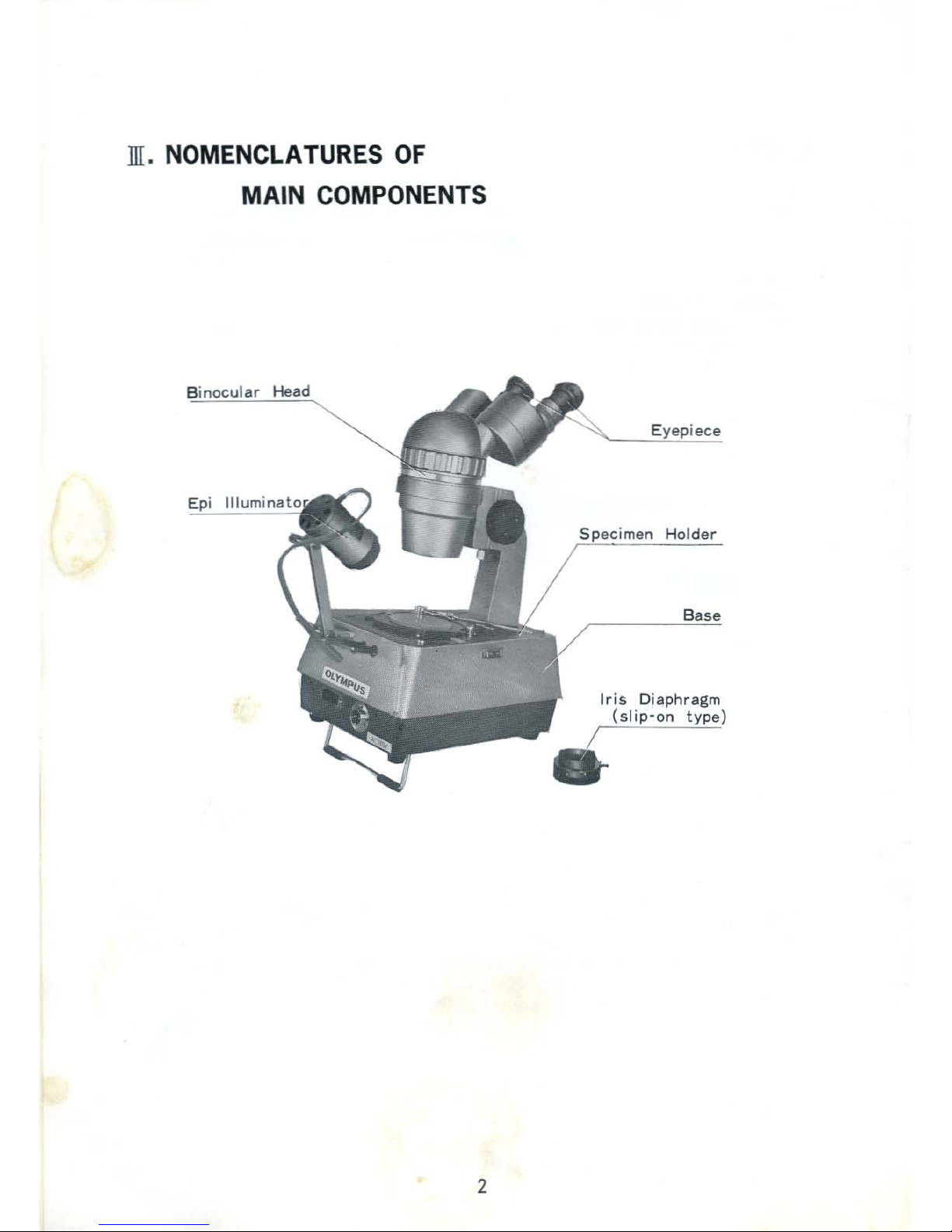
ill.
NOMENCLATURES
OF
MAIN
COMPONENTS
Binocular Head
2
Eyepiece
Holder
Base
Ir
is Diaphragm
(slip·on
type)
Page 5

IV
. OPTICAL SYSTEM
P.
L.
Ob
f~
~
\\
"~
YV
",
lb--
~
~
I
\
\.~-
1. For
Observation
The beamfrom
the specimen
enter
s the obs
erva
tion
tube
at an angle of 12.0The
beam , pas
sin
g through the
cbj
ect
tve-Ob
.rthe
zoomi
ng variation sy
stem-zt.sand I Lz" and
the
fixed t
ens-L,
'', reaches t he Pr
ism"PI"
whereitassumes45° in
cli
nat ion. Via t he por ro
-cr
tsms
"Ptand Pa''
th
e beam finall y reachesthe eyepieces -O
c".Cont
inuous z
oom
ing variat ion
is availa ble by means of the ZL lenses.
2.
Illum
inating
System
Lig
ht emitted from t he li
ght
sour ce "Q1"proceeds intwo directions. or:e to i
llum
inate
th
e specimen vert ica
llythro
ughthe frosted p
late
"F
1
"
and
the
other to be
refle
cted
as
indicated by a
rro
ws on the
largereflect
ing mirror "M"whichsurrou
nds the l
ightsource
.
The
ligh
t ref lected on mir ror
"
M~
then proceedsthrough
the
bow
l-like f
rosted
plate"F!"
to illuminatethe specimen
fromth
e bord er. When
the
shutter"5"
is stopped
down,th
e
vertical ill uminat ion is shut o
ff,
leaving the border illumina
tio
n alone , i. e. the dark-field
illu
mination
. Further, when
the
iris dia
phr
agm "0 " isstopped
down,dark-field
effectis
increased, because the beams
with
a small angle a wi ll be
stopped
. Onthe
other
hand,
li
ght
emittedfrom the light source " Q!" proceeds
through
the
condenser lens "CL" to
illumi nat e the specimen
fr
om an ob
lique
direction.
3
Page 6

V. STRUCTURE
A. Microscope
Die ter Rings
To
.djll
st diopterof
and
ldl
cyu.
Magnification
kldicator
Focusing
Knobs
Mounti Block
To ",ounl th.
m;cT<>S<'ope
....to
the......
Fi
ll.in
g Screw
T o clamp t hc
micro.copen<orely
on the..m.
B.
Base
Mi
croscope
Supporting
Cap
for
Specimen
Holder
Mount
I
ris
Diaphr agm
Diaphr agm
Control Knob
Inclined """- .
I
lluminat
or Mount
'<,
Jac
ks f or
Illuminator
~pare
Ter mi
Co
llap
sible Leg/
4
Prism BOll
rllra
ill 1M di ....cti
i.
iut
by . r.......
lor
;nurp.lpill
,.
di,tnn
..lin
iment.
Variable
Me
nifica
tion Ring
Whftl
I\I
~
ilIDona
1M 100.di1lJ left
....
lo .
!>.onge
I".,,,,i
ll,
"'"l[1Iili ol ti O"".
Variable MlIgnification
indicator R
in&
Head Fixing Screw
'010",- lonHOled. ;1
.i
ll
.11.... 1M hcad 360·
ro"
';OII.
Hood
Head Suppor ting Block
Mm
Specimen
Holder Mount
Inclined
Illuminator Mourit
/
Page 7

C. Specimen Holder
H odie
The
Spec
imen may be moved
in ....y direction.
D.
Power
Source
Se
lector
E. Epl
illuminator
CLSG· II )
Plugs
Arm Fixing Handle
Anile of the . rlll
",.y
~
th
n•..,l as <
<'Q
uir
e<!
.
Ve
nti
lat
ion Holes
Focus·
Handle
Filter Holder
32
.$f
Iihu_,"'"
••"cWo!.
5
Clip
l
Fill
Metal
Main Sw
itch
Mounting Block
FiJlj
rli
Scr ew
Mo.....
tin
g Block
Univ
ers
al .JointFixing Handle
Unive
rsal
..Joi
nt
Page 8

\1. ASSEMBLY
1. Set t he m icr oscope
onto
the
suppor
tin
g block
of
the
arm and se
cur
eittigh
tlywith
the p
rov
ided sc
rew
. ( Fl
g.L)
(Fig. I )
2. The
headiscla
mped with
the
head
fixing
screw.
(Fig.
2)
3. Remove the eyepiece caps from t he eyep iece
tubes and inse
rt
pro
per eyepieces.
4. Inst all
the
specimen hol
der
(either
at
the
rig
ht
or the leftmount ) (Fig.
3)
5. Mountthe Epi
ill
um inator ontotheillum
inator
mount on
the
base and tigh
tenthefixing screw.
Inser t t he plugs of
the
illum
inatorintoth
e ja
cks
.
(Fig.
4)
6.
Ins
ert
the line cord intothe input term inal on the
base, and screw it securely.
Connectthe
other
plug
of
line co rdtothe
AC
outlet
.
6
(Fig.
2)
(Fig.
3)
(Fig.
4)
Page 9

vll.
OPERATION
2. Set
the
Bright
/Dark
Field
SelectorSwit
ch t o
the
B posit ion.
1. Turn on t he MAIN swi
tc
h and
setthe selector
switchto
the
DIA po
siti
on.
(Fig.
5)
,
h
older
, so
above
the
4. Di
optr
ic adjustme
nts
.
3. Place tne specimen on the specimen
th
at
it wi
ll
be pos
iti
oned
aboutlO
mm
center of
the
iris
diaph
rag
m. (Fig.
5)
a. Firsta
lign
thediopter
rin
g on
the
right
eyepiece
tube
to
"0 ", Set
the
var
iab le
ma
gnification
indicator
ringatthe
max
imum
index 01" 4", Focus on the sepectmen wi t h
the
focusing knob. (Fig.G)
b. Turn the vari
able
magnific
at ion indicator
ring
to
the
min
imum index
of
~
O.
7".
but
do not move the specimen or the focusing
knob
at
this t ime.
(Fig.
6)
c. If the specimen is out
of
focus, do
not
move
thefocusin g
knob,but
turn
the
right
dio
pter
ring
tofocus a
gain
. (Fig.
7)
d. Now ,
turn
the
vari abl e magn
ificat
ion indict or
ring t o
~4".
If
the
specimen is st
ill
out of
foc
us, re
peat
st
epsa.thr
ough c. above.
e. Turn t he le
ftdiopter
ring
toadjust
the l
eft
eyepiece di
opter
.
(Fig.
7)
Now
both
eyepiece tubas have been
adjusted
to
meet
your eye acuity.
Remember
the
index n
umbers
on
the
diopter
rings, so
that
you can
always
adjust
the
eyepiece
tubes
quickly
and corr ect ly. In
making
dioptricadjustments
easier,itis ad
visable
to use as
thin
a specimen as p
ossible
or elsetoc
hoo
se
a specif ic
spotonthe
specimen to be used as
the
focusingpoint
.
7
Page 10

5. Rotate
the
pr ism-boxes(ri
ght
and l
eft)to
adjus
t
the
interpupi
llary
dist ance. (Fig.B)
(Fig.B)
6.
Set
the
variab
le magnif icat ion indicator ring
at
the
required
magnificatio
n for obse rva tion.
(Fig.9)Although
the specim en may be once
set
on
thestage,
illuminat ion effect
may
be s
ligh
tly
d
ifferentdepending
upo
n the position of the
spec imen. In s
uch
a case, move t he specimen
s
lightly
while keepi ng it in
focusbythe
focus
ing
'
knob .
(Fig.
9)
7. Set
the
bright
/dark
field
selector
swich
toDfor
the
dark-fie
ld i
llumination
. The
iris
diaph
ragm
is used
to
adjust
the
angle of
dark-fie
ld il
lumi
nation.
The mo re
theiris
diaphragmisstopped
down,
the
more
the
illuminat ion is
limited,
increasing the
effect
of
the
dark-fielb
illumination
.
8. For use
of
the Epi i
lluminator,set
the se
lector
switchof
the
power
sourse
unittothe
EPI posi
tion
. If
it
is used in
combination
with
the
brightfield
or
darkfieldillumination
,
turn the
switchtothe
EPI·DIA
position.
The
focus
ing handle of the Epi i
llum
inator
is able
to
broaden or
narrow
down
the
ill
uminated
area.
g. Bulb
Change:
When the bulb is
brokenreplace
it w
ith
a new one in
thefollowing
menner :
(For
Bright
/Dark Field Ill
umination
bulb
)
a. Remove the eyepieces
from
the
eyepiece
tubes
and
take
off
the whole microscope
bodyfrom
the
arm.
b. Remove
the
specimen
holder
from
the
stage.
c. Lay down the
stage,
remove
the
socket
holder
ring, and
pull
out
the
socket.
(Fig. l O)
d. Remove the
bulb
by
turningitcountercloc
k-
wise, and replace it.
(Fig.l O)
8
Page 11

@Use of Heat Absorbing Glass
This tube covers the bulb of the bright
/da
rk
field illumination, and absorbs heat emitted
from the illuminator bulb.
I
(For inclined illuminat ion bulb) Hu t
Abmbi
nl Gl.
..
1
Turn the focusing handle of the illuminator
counter-clockwise, and it will be easily released from
the illuminator. Then replace the bulb.
(Fig.11)
10
. Use of Iris Diaphragm (slip-in type)
Turn up the Epi illuminator and put the iris
diaphragm on it. If you place a gem on the
diaphragm and match the aderture of the diaphragm
to the size of the gem, switching on the illuminator,
it instantly provides a simple method to examine
the gem.
1m
.
OPTICAL
CHARACTERIS
TICS
...
(Fig.l
l)
Magnification
Total
Actual
IWorking
Eyepiece Indicator
Value
Magnification
Viewfie id(mm)j Distancs (mm)
0.7 7X
31.4"
88
1
lOX
22.0
"
1.5 15X
14.7
"
2 20X
11.0
"G
I0X
2.5 25X
8.8
"
--
-
3
30X
7.3 u
3.5 35X
6.3
"
4 40X
5.5
u
0.7 14X
17.4
88
1 20X
12.2
"
1.5 30X
8.1
"
2
40X 6.1
"
G20 X
2.5
SOX
4.9
u
3 60X 4.1
"
3.5
70X 3.5
"
4 80X 3.1 u
_.
9
Page 12

OLYMPUS
OPTICAL COy LTD.
43-2,
HATAUTA
2'(HOME,
SHIBUYA-IU,
TOIYO,
lAU
••
7607 802 Printed in Japan
 Loading...