

Olympus IX-FLA User manual
OLYMPUS
IX-FLA
INVERTED
OBSERVATION
REFLECTED
INSTRUCTIONS
LIGHT
FLUORESCENCE
ATTACHMENT
This
instruction
Observation
with
the
before
use
operating
manual
Attachment.
of
this
attachment,
the
attachment
is
To
for
obtain
the
Olympus
optimum
we
recommend
IX-FLA
Inverted
performance
that
and
you
Reflected
to
familiarize
study
this
Light
Fluorescence
yourself
manual
thoroughly
fully
AX5918
IMPORTANT
This
unit
employs a UIS
UIS
microscope
if
inappropriate
a
Getting
This
attachment
Operating
N=
Installation
.
The
Make
Control
The
σσβω
to
s
Do
parts
Do
The
.
To
Before
and
minutes
‘The
allow
.
When
and
temperature
category
high
pressure
sure
that
ultraviolet
use
the
not
open
will
be
not
apply
power
avoid potential
opening
unplug
or
temperature
ample
installing
surrounding
frames,
accessories
Ready
is a precision
and
(overvoltage
mercury
that
the
power
the
burner
is
rays
UV
protective
the
lamp
extremely
excessive
supply
the
the
lamp housing's
more
free
the
walls
installed
emitted
shield
housing
hot
force
unit
contains
shock
hazard,
lamp
housing
until
the
the
vicinity
space
around
power
to
lamp
prevent
in
supply
(universal
eyepieces,
instrument.
relative
burner
supply
infinity
condensers,
are
used.
humidity
category)
I
(mercury
unit's
main switch
correctly
by the
burner
are
with
the
while
and
to
unit.
the
burner
will
cause
the
stop
high
be
mechanisms
voltage
sure
to
for
replacement
connecting
housing
the
lamp
and
in
particular
unit
(BH2-RFL-T3),
cools
of
overheating.
system)
etc.
Handle
it
with care
should
be
in
(in
accordance
arc
lamp)
and
that
harmful
(See
is
thermal
the
should
is
set
all
cords
and
should
page
10.)
turned
on
injury
if
that
components.
ground
the
power
of
the
plug
from
burner
cord
down.
housing
will
greatly
above
the
ensure
optical
design, and
Less
than
and
avoid
range
of
with
0°-40°С
IEC664).
Pollution
be a USH102D
to O (OFF).
are
or
for
touched,
all
the
Never
cord
the
output
lamp
that
If
correctly
not
be
directly
at
least
(See
functions
attempt
wire.
or
other
connector
increase.
housing
there
is
should
optimum
subjecting
performance
it
to
(32°-104°F)
degree
(mfd,
not
10
page
to
internal
When
more
by
so,
set
connected.
minutes
are
the
looked
at
after
12)
provided
disassemble
parts, set the
on the
installing the
than 5 cm
be
used
sudden
or
and
30-90%,
II
(in
accordance
Ushio
Electric)
main
switch
with
unprotected
it
is
turned
with.
the
unit
main
power
supply
microscope,
free
space
only
with
may
result
severe
impact.
respectively.
with
to O (OFF)
eyes.
off.
Lamp
switch
to © (OFF)
unit,
Wait
make
between
IEC664)
Be
sure
housing
for
10
sure
to
its
sides
・
a
Maintenance
ἂν
Be
careful
clean
xylene
*
Since
potential
any
neutral
2
Do
not
3
The
replace
4
When
5.
If a dichroic
a
Caution
If
the
addition,
60
safety
The
in
the
and
and
avoid
by
wiping
or a mixture
ether
leaving
gently
of
and
sources
components
detergent.
disassemble
mercury
burner
the
not
equipment
the
has a service
bumer
with a new
using
the
mirror
cube
is
equipment
symbols
following
|
symbols
safest
possible
Indicates
Before
ΡΕ]
Indicates
Storage
dirt
or
with a piece
ether
alcohol
of
(especially
any
attachment,
used
are
fingerprints
of
gauze.
(70%)
and
are
electrical
alcohol
highly
sparks,
plastic
part
of
the
attachment.
life
of
200
one.
(See
keep
is
not
in a manner
may
also
found
it
going
to
not
be
damaged.
on the
microscope.
manner.
that
the
surface
use,
carefully
read
that
the
main switch ON.
on the
lenses,
To
remove
(30%).
flammable,
such
as
parts).
page
covered
be
main
To
clean,
hours.
When
10.)
with
used
for a while,
specified
Always
becomes
the
instruction
fiters,
or
fingerprints
be
careful
switches.
the
or
oil
to
keep
Never
use a lint-free, soft
the
hour
counter
the
provided
dust
place
it
in
by
this
manual,
used
Study
the
the
the
equipment
meaning
Explanation
hot,
and
should
not
manual.
high
pressure
stains,
wipe
with
these
chemicals
attempt
to
cloth
on the
power
cover
and
its
safety
of
the
be
store
container
of
the
as
outlined
symbols,
touched
mercury
burner.
gauze
slightly
away
use
organic
lightly
moistened
supply
unit
it
at a dry,
and
store
it
in a safe
equipment
in
this
instruction
and
always
with
bare
hands.
If
contaminated,
moistened
from
open
solvents
with
fire
and
to
clean
with a diluted
indicates
200
hours,
clean
place.
place.
may
be
impaired.
manual
use
the
microscope
in
Indicates
ο-
that
the
main switch
OFF.
om
ш
dsev
3-1
Module
3-2
Detailed
@
Е
sine
conteos...
observaron
5-1
Summary
5-2
Simultaneous
Light
5-3
Simultaneous
Light
“TROUBLESHOOTING
System
Assembly
rue
Phase
Differential
Chart
of
Observation
Reflected
Contrast
Reflected
Interference
Procedure
Procedures
Light
Fluorescence
Observation
Light
Fluorescence
Contrast
GUIDE
O
and
Transmitted
and
Transmitted
Observation.....
«+
e
~
19
20
„.
20
恩
A
πα
A
国
S
=
‘
g
AUNLVTONAWON
3INaOW
a
=
>
=
RI
ミ
S
>
に
つり
X
四
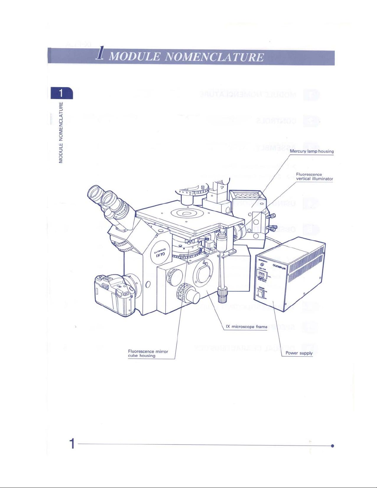
Mercury
lamp
housi
x
G
È
$
a
8
£
$
9
ONTROLS
@
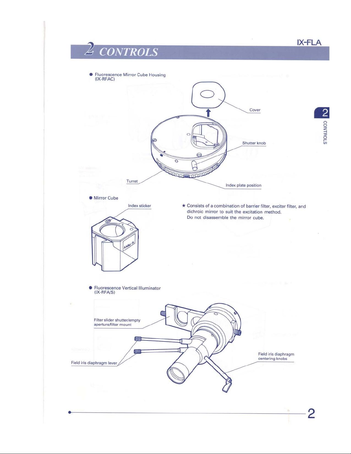
Fluorescence
(IX-RFAC)
Mirror
Cube
IX-FLA
Housing
©
Mirror
Cube
Turret
Index
sticker
à
—
*
Consists
dichroic
Do
not
À
Index
plate
of a combination
mirror
to
suit
the
disassemble
the
mirror
>=
Shutter
knob
=
position
of
barrier
filter,
excitation
method.
cube.
exciter
filter,
and
=
3
2
은
=
Field
iris
@
Fluorescence
(IX-RFA/S)
Filter
slider
apertureffilter
Vertical
shutter/empty
mount
diaphragm
lever
Illuminator
diaphragm
centering
knobs
©
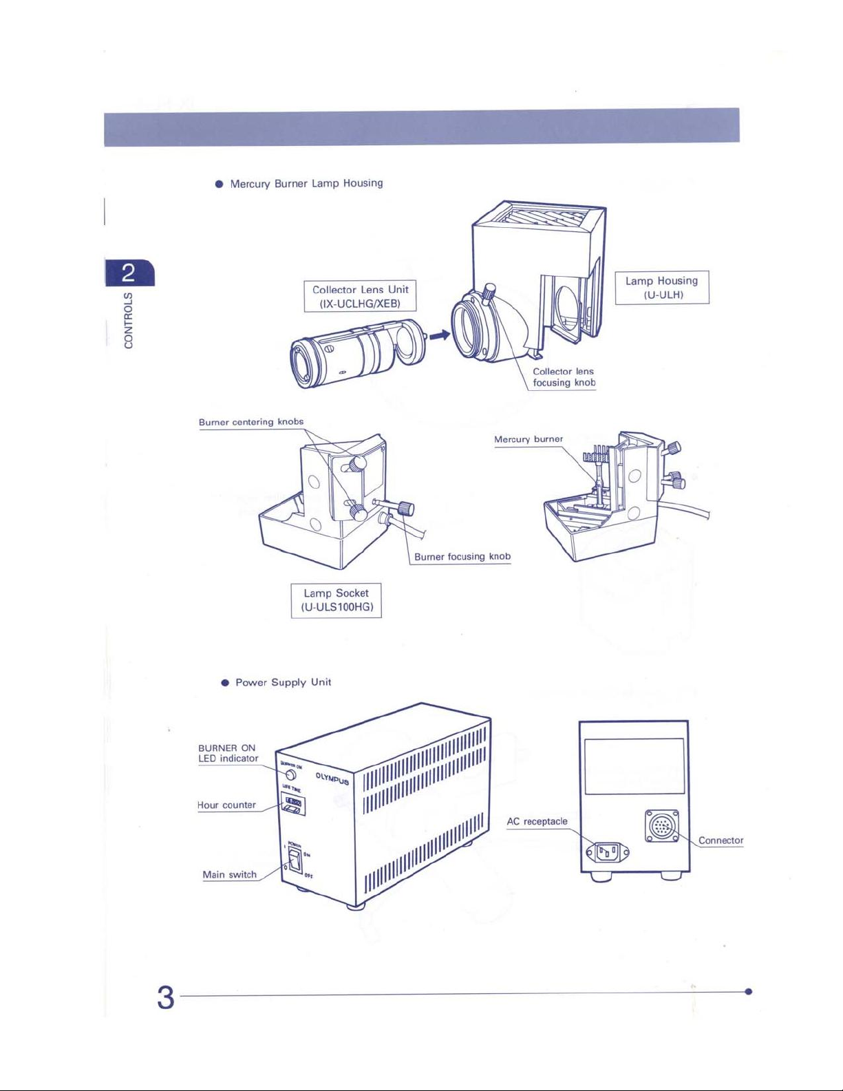
Mercury
Burner
Lamp
Housing
5
CONTROLS
Collector
ollector
(IX-UCLHG/XEB)
Lamp
Socket
(U-ULS100HG)
Li
Lens
Unit
Lamp
i
Collector
focusing
lens
knob
Housing
(U-ULH)
@
BURNER
LED
indicator
Hour
counter
Power
ON
Supply
Unit
AE
receptacle
Connector
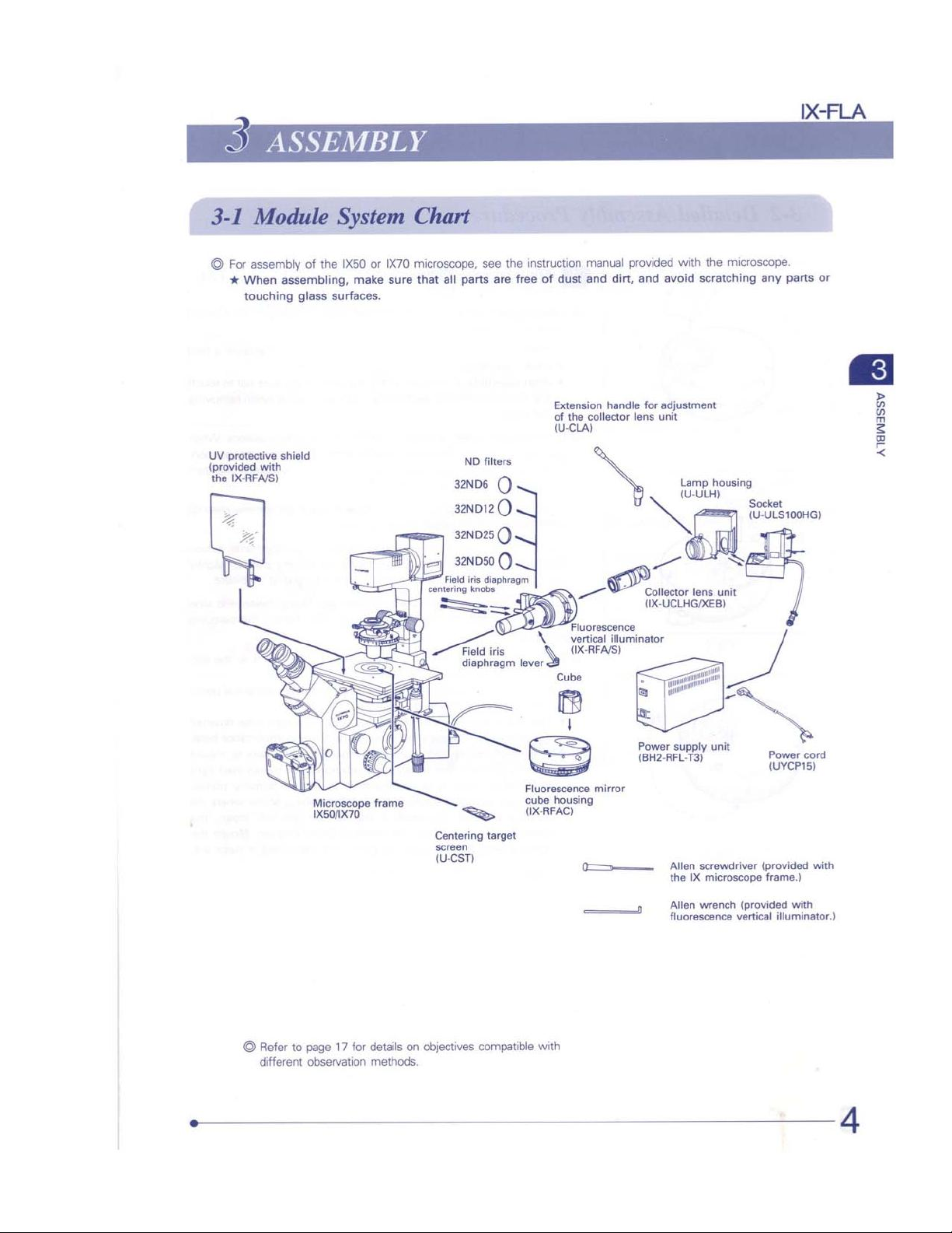
©
For
assembly
*
When
assembling,
touching
ho
ASI
glass
of
the
IX50
make
surfaces.
or
IX70
microscope,
sure
that
=
see
all
parts
are
замов
32ΝΟΙ2().
32ND25
32ND50
diaphragm
iris
Field
knobs
centering
1010
iris
diaphragm
the
instruction
free
of
dust
Extension
of
(UCLA)
()
()
()
\
verd
Cube
manual
provided
and
dirt,
and
handle
the
collector
Fluorescence
vertical
(XRFAS
for
lens
>
Collector
(IX-UCLHG/XEB)
Muminator
jes
with
avoid
adjustment
unit
Lamp
ss
the
microscope.
scratching
housing
ULH)
any
Ноно
unit
lens
parts
or
A
ATSNISSV
©
Refer
different
i
1x501x70
to
page
17
observation
for
details
methods.
Centering
screen
(U-CST)
on
objectives
cS
=>
cube
UX-RFAC)
target
compatible
housing
with
mirror
=
Power
supply
(BH2-RFL-T3)
3
unit
Allen
screwdriver
the
IX
microscope
Allen
wrench
fluorescence
Power
cord
(UYCP15)
(provided
frame.)
(provided
vertical
with
illuminator.)
with
3
ASSEMBLY
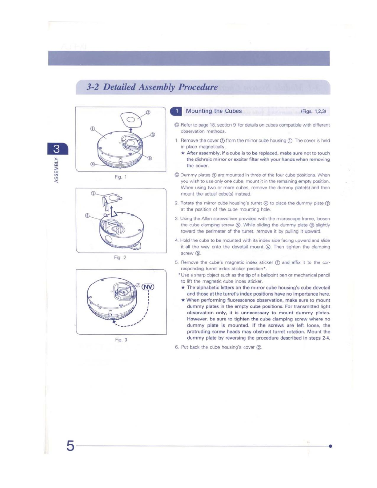
@]
Mounting
©
Refer
to
observation
1.
Remove
in
place
*
After
the
dichroic
the
cover.
©
Dummy
you
wish
When
using
mount
2.
Rotate
the
at
the
position
3.
Using
the
the
cube
toward
4.
Hold
the
it
all
the
screw
©.
5.
Remove
responding
*Use a sharp
to
lift
the
*
The
and
*
When
dummy
observation
However,
dummy
protruding
dummy
6.
Put
back
the
page
18,
section 9 for
methods.
the
cover @ from
magneticaliy.
assembly,
mirror
plates @ are
to
use
only
two
or
the
actual
mirror
of
Allen
screwdriver
clamping
the
perimeter
cube
to
be
way
onto
the
cube’s
turret
object
magnetic
alphabetic
those
at
the
performing
plates
only,
be
sure
plate
screw
plate by
the
cube
Cubes
details
the
mirror
if a cube
cube(s)
cube
the
or
exciter
mounted
one
cube,
more
cubes,
instead.
housing's
cube
is
to
in
mount
mounting
provided
screw
©.
While
of
the
turret,
mounted
the
index
such
cube
letters
turret's
in
is
housing's
with
dovetail
magnetic
fluorescence
the
heads
reversing
sticker
as
the
tip
index
on
the
index
empty
it
is
unnecessary
to
tighten
mounted.
may
index
cover
on
cubes
compatible
cube
housing
be
replaced,
filter
with
your
three
of
the
four
it
in
the
remaining
remove
the
dummy
turret @ to
sliding
remove
its
mount
place
hole.
with
the
microscope
the
it
by
index
side
©.
Then
sticker @ and
position".
of a ballpoint
sticker.
mirror
cube
housing's
positions
observation,
cube
the
If
obstruct
the
procedure
have
positions.
to
mount
cube
clamping
the
screws
turret
©.
(Figs.
with
©.
The
cover
make
sure
not
hands
when
cube
positions.
empty
platels)
the
dummy
frame,
dummy
plate @ slightiy
pulling
it
upward
facing
upward
tighten
the
affix
it
to
pen
or
mechanical
cube
no
importance
make
sure
For
transmitted
dummy
screw
are
left
loose,
rotation.
described
Mount
in
1,23)
different
is
held
to
touch
removing
When
position.
and
then
plate
@
loosen
and
slide
clamping
the
cor-
pencil
dovetail
here.
to
mount
light
plates.
where
no
the
the
steps
2-4.
IX-FLA
Fig.
5
Mounting
Cube
%
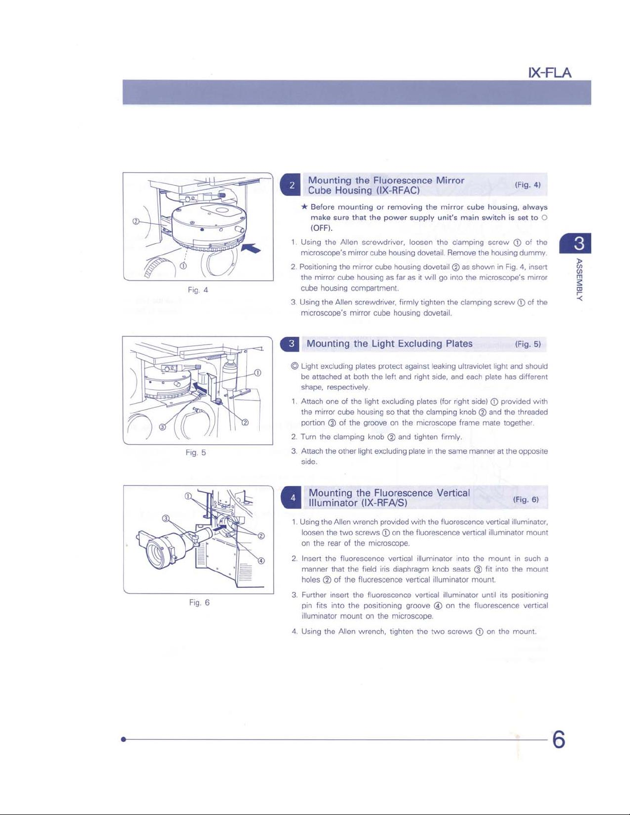
Before
make
(OFF).
1.
Using
the
microscope's
2.
Positioning
the
mirror
cube
housing
3.
Using
the
microscope's
a
Mounting
©
Light
excluding
be
attached
shape,
respectively.
1.
Attach
one
the
mirror
portion @ of
2.
Turn
the
3.
Attach
the
side.
the
Fluorescence
Housing
mounting
sure
Allen
the
cube
Allen
at
of
cube
clamping
other
(IX-RFAC)
or
that
the
screwdriver,
mirror
cube
mirror
cube
housing
compartment.
screwdriver,
mirror
cube
the
Light
plates
protect against
both
the
the
light
excluding
housing
the
groove
knob @ and tighten
light
excluding
removing
power
the
supply
loosen
housing
dovetail.
housing
dovetail @ as
as
far
as
it
will
firmly
tighten
housing
dovetail.
Excluding
left
and
right
plates
so
that
the
clamping
on
the
microscope
plate
in
Mirror
mirror
units
main
the
clamping
Remove
go
into
the
clamping
Plates
leaking
ultraviolet
side,
and
(for
right
knob @ and
frame
firmly.
the
same
(Fig.
본
cube
housing,
switch
always
is
set
screw © of
the
housing
dummy.
shown
in
Fig.
4,
insert
the
microscope's
mirror
screw @ of
(Fig.
light
and
should
each
plate
has
different
side) © provided
the
threaded
mate
together.
manner
at
the
opposite
4)
to
O
the
the
5)
with
В
ATBNISSY
Fig.
6
Mounting
Illuminator
1.
Using
the Allen
loosen
the
on
the
rear
ο
.
Insert
the
manner
holes @ of
so
Further
pin
fits
illuminator
5
Using
the
the
(IX-RFA/S)
wrench
two
screws © on
of
the
fluorescence
that
the
field
the
fluorescence
insert
the
into
the
positioning
mount
Allen
wrench,
Fluorescence
provided
microscope.
iris
fluorescence
on
the
with
the
fluorescence
vertical
diaphragm
vertical
vertical
groove © on
microscope.
tighten
Vertical
the
fluorescence
illuminator
the
into
knob
seats © fit
illuminator
illuminator
two
screws © on
vertical
vertical
illuminator
the
mount
mount.
until
the
fluorescence
6)
(Fig.
illuminator,
mount
in
such
a
into
the
mount
its
positioning
vertical
the
mount.
3
ASSEMBLY
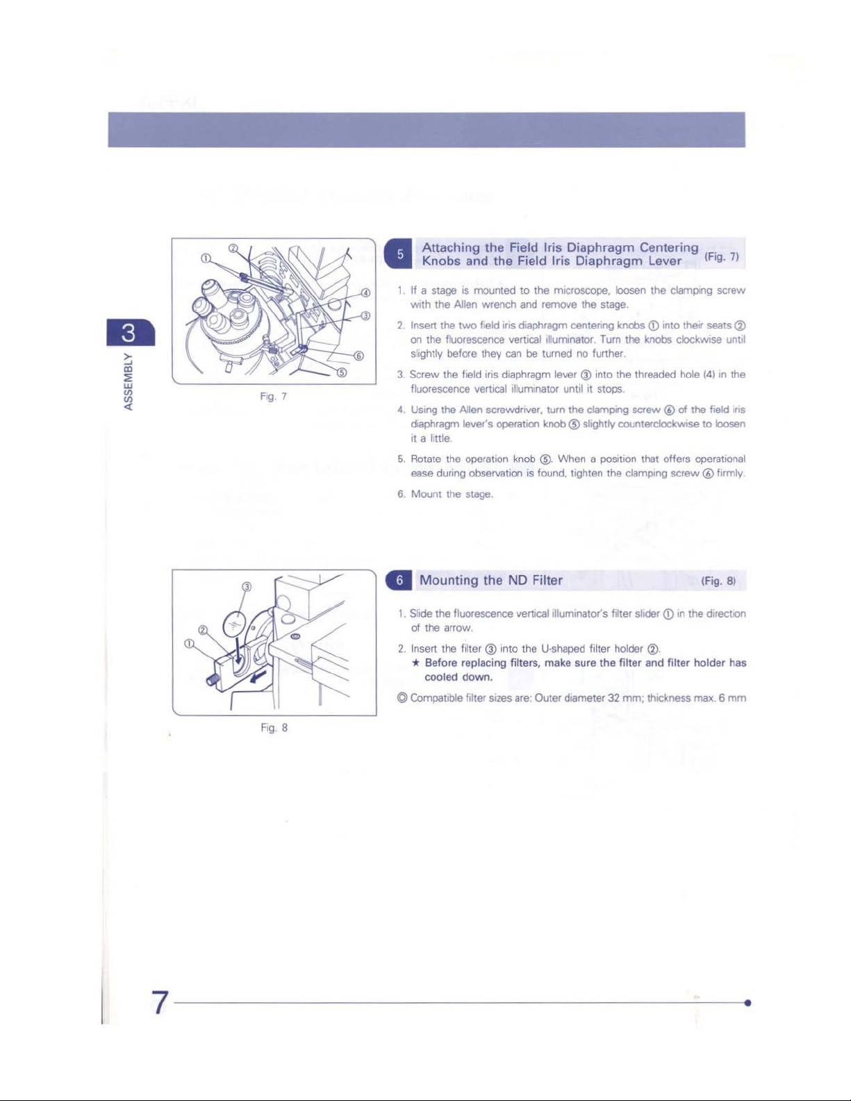
Attaching
Knobs
1.
If a stage
with
Insert
N
on
the
slightly
“
‘Screw
fluorescence
4.
Using
diaphragm
it a little.
σι
Rotate
ease
Mount
o
G
wounting
1.
Slide the
of
the
2.
Insert
x
Before
cooled
©
Compatible
the
and
is
mounted
the
Allen
wrench
the
two
field
fluorescence
before
they
the
field
iris
vertical
the
Allen
screwdriver,
lever's
the
operation
during
observation
the
stage.
the
fluorescence
arrow.
the
filter @ into
replacing
down.
filter
sizes
Field
the
Field
to
and
iris
diaphragm
vertical
can
be
diaphragm
illuminator
operation
knob
is
ND
Filter
vertical
the
filters,
are:
Iris
Diaphragm
Iris
Diaphragm
the
microscope,
remove
centering
illuminator.
turned
lever @ into
until
turn
the
knob © slightly
©).
When a position
found,
tighten
illuminator's
U-shaped
make
Outer
diameter
loosen
the
stage.
Turn
no
further.
the
it
stops.
clamping
the
filter
filter
holder
sure
the
32
Centering
Lever
the
clamping
knobs
(7)
into
their
the
knobs
clockwise
threaded
screw © of
counterclockwise
clamping
slider © in
filter
mm;
hole
the
that
offers
operational
screw @ firmly
the
@).
and
filter
holder
thickness
max. 6 mm
(Fig.
7)
screw
seats
©
until
(4)
in
the
field
iris
to
loosen
(Fig.
8)
direction
has
 Loading...