

Olympus IX73 Instructions Manual
IX73
INSTRUCTIONS
RESEARCH INVERTED MICROSCOPE
This instruction manual is for the Olympus research inverted microscope model IX73.
To ensure the safety, obtain optimum performance and to familiarize yourself fully with the use
of this microscope, we recommend that you study this manual thoroughly before operating the
microscope.
Retain this instruction manual in an easily accessible place near the work desk for future reference.
A X 8 1 5 7

In accordance with European Directive 2002/96/EC on Waste Electrical and Electronic Equipment, this symbol indicates that the product must not be disposed of as unsorted municipal
waste, but should be collected separately.
Refer to your local Olympus distributor in EU for return and/or collection systems available in
your country.

1
Intended use ...............................................................................................................................................................................................4
2
Conformity of the System ................................................................................................................................................................5
3
Handling Precautions..........................................................................................................................................................................6
4
Maintenance and Storage ..............................................................................................................................................................6
1 MODULE NOMENCLATURE .................................................................................................7
2 NOMENCLATURE ..........................................................................................................................8
3 TRANSMITTED LIGHT BRIGHTFIELD OBSERVATION PROCEDURE .12
4 USING THE CONTROLS ..........................................................................................................14
4-1 Power Supply Unit and Microscope Frame .......................................................................................14
1
Turning Power On, Adjusting the Brightness ................................................................................................................. 14
2
Light Path Selection .............................................................................................................................................................................. 15
3
Coded intermediate magnification changer IX3-CAS ....................................................................................................... 15
4
Frame Fix Plate IX3-FP ....................................................................................................................................................................... 15
5
Dust tray .......................................................................................................................................................................................................... 16
4-2 Focusing Block............................................................................................................................................................17
1
Rotation Direction of the Coarse/Fine Adjustment Knobs .......................................................... 17
2
Adjusting the Coarse Adjustment Knob Tension ....................................................................................................... 17
3
Detaching the Fine Adjustment Knob .................................................................................................................................. 17
4
Pre-focusing Lever .................................................................................................................................................................................17
4-3 Stage ....................................................................................................................................................................................18
1
Placing the Specimen ........................................................................................................................................................................18
2
Moving the Specimen.........................................................................................................................................................................21
3
Connecting the Grounding Wire ............................................................................................................................................... 22
IMPORTANT -- Be sure to read this section for safe use of the equipment. -- 1-6

4-4 Observation Tube ......................................................................................................................................................23
1
Adjusting the Interpupillary Distance ....................................................................................................................................23
2
Adjusting the Diopter ........................................................................................................................................................................... 23
3
Using the Eye Shades ........................................................................................................................................................................24
4
Mounting the Eyepiece Micrometer Disk .......................................................................................................................... 24
5
Selecting the Light Path of the Trinocular Tube ...........................................................................................................24
6
Adjusting the Tilt (U-TBI90) ............................................................................................................................................................. 24
4-5 Illumination Column (IX3-ILL) ..........................................................................................................................25
1
Tilting the Illumination Column ...................................................................................................................................................25
2
Mounting Filters........................................................................................................................................................................................26
3
Using the Field Iris Diaphragm ................................................................................................................................................... 27
4
Adjusting the Condenser Height Adjustment Knob Tension ...................................................................................................................27
5
Condenser refocusing stopper .................................................................................................................................................. 27
4-6 Condenser ......................................................................................................................................................................28
1
Centering the Condenser ................................................................................................................................................................ 28
2
Using the Aperture Iris Diaphragm ......................................................................................................................................... 30
4-7 Oil- or Water-Immersion Objective ..........................................................................................................31
1
Using Oil- or Water-Immersion Objective ......................................................................................................................... 31
4-8 Objectives with Correction Collar ...............................................................................................................32
5 OTHER OBSERVATION METHODS .................................................................................33
5-1 Phase Contrast Observation ...........................................................................................................................33
1
Phase Contrast Optical Elements and Applicable Objectives ....................................................................... 33
2
Attaching the Phase Contrast Optical Elements ........................................................................................................ 34
3
Centering the Phase Contrast Ring Slit .............................................................................................................................. 36
5-2 Differential Interference Contrast Observation ................................................................................37
1
DIC Optical Elements, Applicable Objectives and DIC Sliders ...................................................................... 37

2
Attaching the DIC Optical Elements ...................................................................................................................................... 38
3
Attaching the Analyzer and DIC Slider ................................................................................................................................39
4
Attaching the Polarizer (IX-LWPO) ............................................................................................................................................40
5
Cross-Nicol Adjustment ....................................................................................................................................................................41
6
Observation Method ............................................................................................................................................................................42
5-3 Simplified Polarized Light Observation .................................................................................................43
1
Attaching the Analyzer and Polarizer .................................................................................................................................... 43
2
Observation Method ............................................................................................................................................................................43
5-4 Reflected Light Fluorescence Observation (Separate Manual) ......................................44
5-5 Relief Contrast Observation (Separate Manual) ...........................................................................44
6 CAMERA RECORDING .............................................................................................................45
1
Camera Adapter ......................................................................................................................................................................................45
2
Changing of Light Path ......................................................................................................................................................................45
3
Selecting the Camera Adapter Magnification ...............................................................................................................45
4
Installing the Camera Adapter ....................................................................................................................................................46
7 TROUBLESHOOTING GUIDE .............................................................................................. 47
8 SPECIFICATIONS ...........................................................................................................................49
9 ASSEMBLY ...........................................................................................................................................50
9-1 Assembly Diagram ..................................................................................................................................................50
9-2 Detailed Assembly Procedures ....................................................................................................................51
1
Attaching the revolving nosepiece .........................................................................................................................................51
2
Mounting the Illumination Column ..........................................................................................................................................52
3
Attaching the Halogen Bulb .......................................................................................................................................................... 52
4
Mounting the Lamp Housing........................................................................................................................................................ 53
5
Mounting to Microscope Deck ................................................................................................................................................... 54

Caution
If the equipment is used in a manner not specified by this manual, the safety of the user may be imperiled. In addition,
the equipment may also be damaged. Always use the equipment as outlined in this instruction manual.
The following symbols are used to set off text in this instruction manual.
CAUTION
: Indicates a potentially hazardous situation which, if not avoided, may result in minor or
moderate injury or damage to the equipment or other property. It may also be used to
alert against unsafe practices.
} : Indicates commentary (for ease of operation and maintenance).
6
Attaching the Stage ..............................................................................................................................................................................55
7
Attaching the Objectives ..................................................................................................................................................................57
8
Attaching the Condenser Refocusing Stopper ............................................................................................................57
9
Attaching the Condenser ................................................................................................................................................................58
10
Attaching the Observation Tube ................................................................................................................................................ 59
11
Attaching the Eyepieces ..................................................................................................................................................................60
12
Using the Accessory Mounting Holes .................................................................................................................................. 60
13
Using the Frame Fix Plate (IX3-FP) ................................................................................................................................................................... 61
14
Connecting the Cables .....................................................................................................................................................................62
15
Cable Distributions ................................................................................................................................................................................ 63
16
Cable Cover .................................................................................................................................................................................................64
10 LAMP HOUSING INSPECTION SHEET ..................................................................... 65
PROPER SELECTION OF THE POWER SUPPLY CORD ............................................................ ................................................... 66, 67

1
IX73
IMPORTANT
This microscope employs UIS2 optical design.
For the applicable modules, please consult Olympus or refer to the latest brochures or Olympus website. Less than
optimum performance may result if inappropriate module combinations are used.
Configuration of Instruction Manuals
Since this microscope is expandable to a variety of systems, separate instruction manuals are prepared so that the
user has to read only the manuals according to the user’s own system.
Manual Name Main contents
IX73
(this instruction manual)
Observation procedures including transmitted light brightfield, phase
contrast and DIC observations
TH4 Halogen lamp power supply unit
REFLECTED FLUORESCENCE SYSTEM
Reflected light fluorescence observation
IX2-MLWCD Mid-long working distance condenser
U-AW
Motorized attenuator wheel
BX3-SSU
Scanning stage with ultrasonic
IX2-GS Gliding stage
IX3-RSPC
Right side port with C-mount
U-CBF
Control box for fast filter wheel and shutter
IX3-CBM/U-HSCBM
Configuration and usage of the modules available in the IX73 motorized system or the IX73 motorized coded system.
U-LEDPS LED Power supply
U-CB5S Control Box for coded function
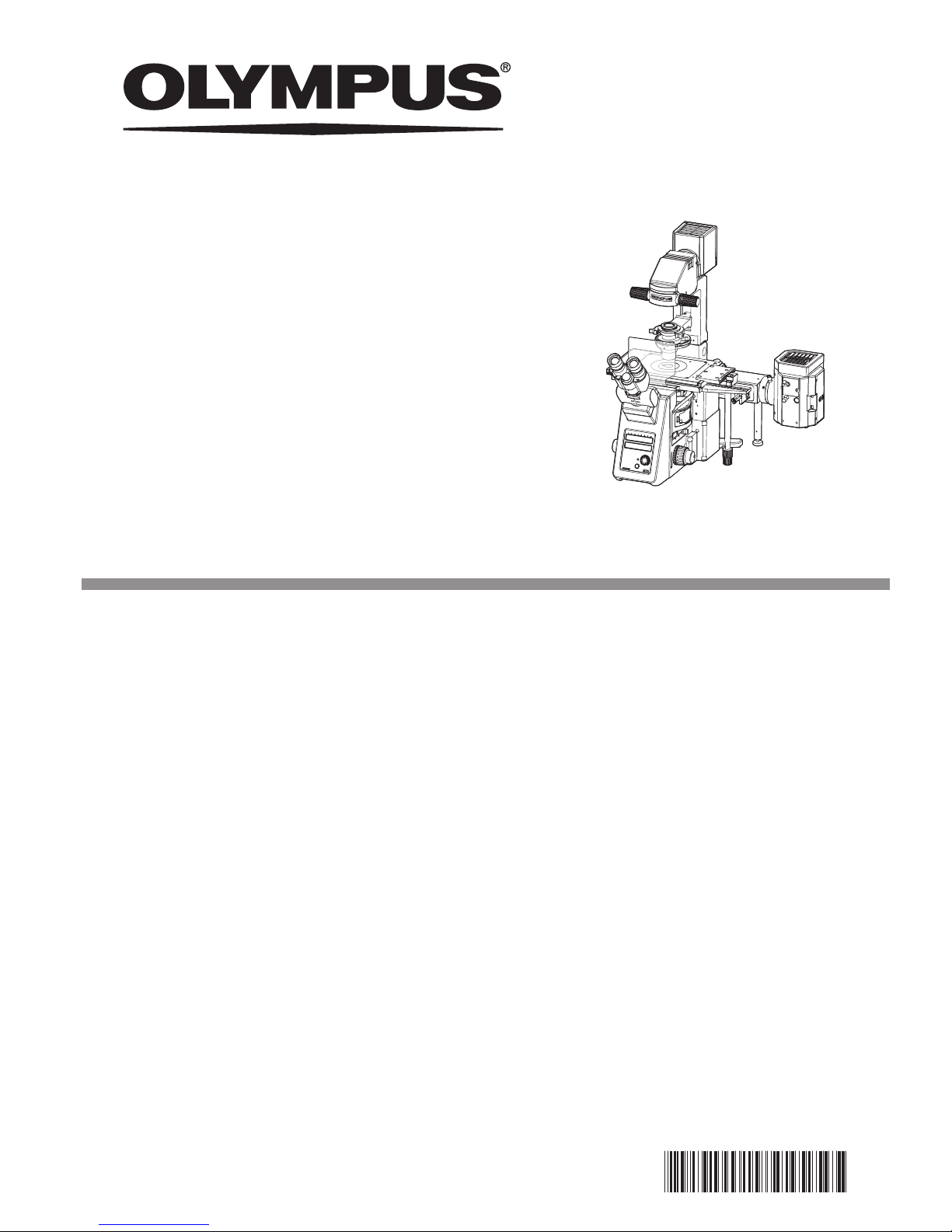
Be sure to work on the following tasks first after finishing the unpacking.
Releasing the Transport Lock
b
a
Releasing the transport lock of the focusing mechanism
Never attempt to rotate the focusing knob without removing the
clamping plate. Otherwise, the focusing mechanism may be
damaged.
Loosen and remove the screws
a
of the clamping plate using the
Allen wrench provided with the microscope.
} Keep the clamping plate and screws in a safe place because it will
be used again when the microscope is transported next time.
Releasing the transport lock of the light path selector
Never attempt to operate the light path selector without removing the transport lock screw. Otherwise, the light path selector
mechanism may be damaged.
Loosen and remove the transport lock screw
b
using the Allen
screwdriver provided with the microscope.
} Keep the lock screw in a safe place because it will be used again
when the microscope is transported next time.
CAUTION
CAUTION
2
SAFETY PRECAUTIONS
b
a
1. If potentially infectious samples may be observed, use protective
gloves or other protective means to prevent the skin from contacting
with samples directly.
After observation, be sure to clean the portion contacted with
samples.
• Moving this device is accompanied with the risk of dropping the
samples. Be sure to remove the samples before moving this device.
• In case the samples are damaged by erroneous operation,
promptly take the infection prevention measures.
• Follow the procedures described in "Handling Precautions" (see
page 6) prior to using the accessories of this device. Otherwise,
the stability of the device will be lost and the dropped samples
will cause the possibility of infection.
• When you maintain the device which may have contacted with
potentially infectious samples, be sure to wear protectors such as
gloves, or clean the device prior to operation.
• Before disposing of the device contacted with potentially infectious samples, be sure to follow the regulations and rules of your
local government.
2. Be careful not to have your hand caught between the bottom of the
revolving nosepiece and the microscope frame.
3. The microscope is not provided with a waterproof mechanism.
Therefore, if culture liquid or water is spilt on the stage, revolving
nosepiece or microscope frame, damage to the equipment or an
electrical shock may result. Immediately wipe the liquid or water off if
it is spilt on them.
4. The microscope is not provided with a dust-proof mechanism.
5. Install the microscope on a sturdy, level table or bench.
6. When moving the microscope, remove the modules that may drop
including the specimen from the microscope in advance, then carefully carry the microscope frame by holding the base (front edge)
a
and the grasping part below the illumination column
b
.
7. When carrying the microscope to a different place, it is also recommended to disconnect all cables and modules from the microscope
frame.
When transporting it, also engage the transport lock mechanisms
and package it sufficiently.
Also be careful against slipping of hands during carrying.
8. Damage to the microscope will occur if you grasp it by other parts
including the stage, focusing knob, etc.
9. This microscope is not equipped with laser safety mechanisms. The
user should assume liabilities for any consequence of user modification including introduction of the use of a laser beam.
10.
If laser equipment is attached to the product you have purchased,
this Instruction Manual is not effective. Follow the Instruction Manual
provided with the laser equipment to be attached.
11 The surfaces of the lamp housing will become extremely hot dur-
ing operation. When installing the microscope, make sure to allow
ample free space (10 cm or more) around and in particular above
the lamp housing.
12. When installing the microscope, route the power cord away from the
lamp housing. Should the power cord come in contact with a hot
part, the power cord could melt and cause electric shock.
3
IX73
c
13. After operation or in case of abnormality, be sure to disconnect the
power cord from the connector on the products or from the outlet.
14. To avoid potential shock hazards and burns when replacing the
lamp bulb, set the main switch to “\” (OFF) then disconnect the
power cord from the wall outlet in advance. Whenever you replace
the bulb during use or right after use, allow the lamp housing
c
and bulb to cool before touching.
Designated bulb 12V100WHAL-L (PHILIPS 7724)
15. Do not permit tools or metal fragments to get into air vents, or other
apertures. Doing so could cause failure of the microscope or electric
shock to the user.
16. The standard service life of the lamp housing is eight (8) years of use
or 20,000 hours of total power ON period, whichever is the shorter
period. For details, see the Inspection Sheet on page 65.
17. During the fluorescent observation, be sure to attach the antiglare
plate to the microscope to protect your eyes.
18. If you feel bright during observation through eyepieces, darken the
illumination light by adjusting the brightness of the light source or
using the ND filter. Use the equipment according to the regulations
for workers health and safety, if any.
– Europe: 2006/25/EC Directive for protecting workers from risks
caused by physical factors (artificial optical radiation).
19. Do not look directly at the light from the objective lens or the specular reflection light of the specimen.
20. Be careful invisible wavelength light (ultraviolet or infrared) may be
emitted depending on illumination methods.
21. If the skin is exposed to the light from the objective lens for a long
time, it may cause burns. Be sure to avoid it.
22. Do not place flammable gas or liquid close to the light from the
objective lens. It may cause fire.
23. This device complies with the emission and immunity requirements
described in IEC61326 series.
24. The electromagnetic environment should be evaluated prior to operation of this device. Do not use this device in close proximity to the
sources of strong electromagnetic radiation to prevent interference
with the proper operation.
25. Always use the power cord provided by Olympus. If no power cord
is provided, please select the proper power cord by referring to the
section “PROPER SELECTION OF THE POWER CORD” at the end
of this instruction manual. If the proper power cord is not used, the
safety and EMC performance of the device can not be assured.
26 Always connect the power cord correctly and ensure that the
grounding terminal of the device and that of the wall outlet are properly connected. If the device is not grounded, our intended electric
safety and EMC performance of the device can not be assured.
27. It is discommended to stare at the light directly from the LED light
source composed in this product for long hours as this could damage your eye. Use the equipment in accordance with the regulations
for Workers Health and Safety, if any.
4
This device has been designed to be used to observe magnified images of specimens in various routine work and
research applications.
Do not use this device for any purpose other than its intended use.
This product complies with the requirements of directive 98/79/EC concerning in vitro diagnostic medical devices. CE marking means the conformity to the directive.
EN61326-1 defines two categories according to the location for use.
Class A : Equipment suitable for use in establishments other than domestic, and those directly connected to a low volt-
age power supply network which supplies buildings used for domestic purposes.
Class B : Equipment for use in domestic establishments, and in establishments directly connected to a low voltage
power supply network which supplies buildings used for domestic purposes.
This product is applied Class A. Some interference may occur if this system is used in domestic location.
USA: CAUTION:
Federal law restricts this device to sale by or on the order of an appropriately licensed healthcare practitioner.
Caution labels
Caution labels are placed at parts where special precaution is required when handling and using the microscope.
Always pay attentions to the caution labels.
Positions of caution labels
Lamp housing
Back side of microscope frame
If the caution label becomes dirty or is peeled off, contact Olympus for replacement.
Safety Symbols
The following symbols are found on the microscope. Study the meaning of the symbols and always use the equipment in the safest possible manner.
Symbol Explanation
Indicates that the surface becomes hot, and should not be touched with bare hands.
Indicates a non-specific general hazard. Follow the description given after this symbol or
in the instruction manual.
Indicates that the main switch is ON.
Indicates that the main switch is OFF.
1
Intended use

5
IX73
Restrictions in use
1) An intermediate attachment with a thickness of up to 60 mm can be mounted between the microscope frame and
binocular observation tube (U-BI90).
2) When the U-AW or U-FSHU is used with the transmitted light illumination setup, periphery of the field of view will
be obscured with the 4X objective. When U-LHEAD is combined with U-AW or U-FSHU, or if U-FSHU is attached to
IX3-ILL directly, the insufficient peripheral light will be mitigated.
3) Image acquisition by the digital camera is not recommended in the combination of U-TV0.35XC and IX3-CAS (2X)
because of an incidence of the spot flare.
4) When the motorized attenuator wheel / fast filter / shutter system (U-AW,U-FFW,U-FSHU) are attached to the reflected fluorescence illuminator (IX3-RFA, IX3-RFAL, IX3-RFALFE) for the fluorescent observation, the peripheral light
becomes insufficient due to obscuring the illumination light.
5) If IX3-RFAL or IX3-RFALFE is mounted such that the lamp house is positioned on the left side facing to the microscope and also the operation part of U-DULHA faces upward, the lamp house to be attached to U-DULHA may
interfere by hitting the camera attached to the left side port.
6) When the U-DPCAD is attached on the left side port, some camera may not be mounted on the back side camera
port depending on its size.
7) When you use IX3-LHLEDC for phase contrast observation / simple polarized light observation / dark field observation / observation with high magnification, if the illumination light is not sufficient, use the halogen lamp housing.
8) If you use IX3-LHLEDC for observation with the 4X objective, uneven illumination becomes slightly larger comparing
to the halogen lamp.
9) If all conditions described below are met, the flares may be noticeable combining IX-ATU + U-TR30 series or UTBI90.
· IX73P1F
· High contrast specimens are being observed.
· Transmitted bright field observation is being used.
· The aperture iris diaphragm is being narrowed down closer to the minimum.
10) If you use 1.6X or 2X of IX3-CAS for the simple polarized light observation using IX3-AN, the contrast may be difficult
to view in some cases.
11) If you use IX73P2F for phase contrast observation or relief contrast observation with IX3-AN engaged in the light
path, a thin shading may occur in the periphery of the field of view. Remove IX3-AN from the light path before observation.
Decks of IX73
The IX73P2F is equipped with two decks, 1st deck (upper deck) and 2nd deck (lower deck), accepting optional accessories such as the intermediate magnification changer, mirror unit cassette, etc. Refer to the following table at the time of
installation of each accessory, since some accessories can be attached on either 1st deck or 2nd deck only.
1st deck(upper deck) 2nd deck(lower deck)
Motorized fluorescent mirror turret : IX3-RFACA
= =
Coded fluorescent mirror turret : IX3-RFACS
= =
Right side port with C-mount : IX3-RSPC
= =
Coded intermediate magnification changer : IX3-CAS
X =
Detail of decks, see page 54.
2
Conformity of the System

6
1. These products are precision instruments. Handle them with care and avoid subjecting them to sudden or severe
impact and also connect the cables gently.
2. Do not use the microscope where it is subjected to direct sunlight, high temperature and humidity, dust or vibrations.
(For operating conditions, see Chapter 8, “SPECIFICATIONS” on page 49.)
3. When attaching or detaching any accessory, make sure to proceed in a condition that nothing is attached on the
left side port.
4. To prevent malfunction, do not replace modules or connect/disconnect cables while the main switch of the IX3CBM is set to “ I ” ON.
5. Do not disassemble any part of the microscope. Doing so could cause failure of the microscope.
6. Before disposing of this product, be sure to follow the regulations and rules of your local government.
1. Do not leave stains or fingerprints on the lenses and filters. Blow away dust with a commercially available blower
and gently wipe the lens or filter with a piece of cleaning paper (or clean gauze).
For wiping fingerprints and oil stains, use a piece of cleaning paper moistened with commercially available absolute
alcohol.
Since the absolute alcohol is highly flammable, it must be handled carefully. Be sure to keep it away from
open flames or potential sources of electrical sparks --- for example, electrical equipment that is being
switched on or off, which could cause ignition of a fire.
Also remember to always use absolute alcohol only in a well-ventilated room.
2. Do not use organic solvents, which cause painted and plastic parts to deteriorate. Do not use organic solvents to
clean device components other than the glass components. To clean them, use a lint-free, soft cloth slightly moistened with a diluted neutral detergent.
3. This microscope is not provided with a dust-proof mechanism. When not using the microscope, make sure to set
the main switch to “\” (OFF), confirm that the lamp housing is cool enough and cover the microscope with the
provided dust cover.
CAUTION
3
Handling Precautions
4
Maintenance and Storage
7
IX73
OM1
PO/OM3
PH/OM4
DIC/OM2
BF/OM5
FL/OM6
ATTENUATOR / DIC
IX3
· IX73P1F
· IX73P2F
Hand switch
U-HSCBM*#
U-CB5S* #
Control box for coded function
· IX3-RFA*
· IX3-RFALFE*
· IX3-RFAL*
IX3-RSPC*
100 W halogen lamp house
· U-LH100L-3
· U-LH100-3+U-RMT
IX3-ILL
Halogen lamp power
supply unit
TH4*
· IX3-RFACA*#
IX3-CBM* #
Control box M
· IX3-RFACS*#
IX3-CAS #
} The modules shown below are only the basic modules. As there are other modules which can be combined with the
microscope but are not shown below, please also refer to the latest Olympus brochures or your dealer.
For information on the modules marked with “*", refer to their instruction manuals.
Modules marked # are components of the IX73 motorized system. Also you can configure the IX73 motorized coded
system in combination with modules marked #. For details, refer to IX3-CBM instruction manual.
Modules marked # are components of the IX73 coded system. For details, refer to U-CB5S instruction manual.
· IX3-LWUCDA #
· IX2-LWUCD
· IX-ULWCD
· IX2-MLWCD*
· U-UCD8*
(Used together
with IX-ADUCD)
Condenser
· IX3-SVR
· BX3-SSU
· IX2-SP
(Used together
with IX-MVR)
· IX2-GS
· GX-SVR
Stage
Eyepieces
· WHN10X
· WHN10X-H
Observation tube
· U-BI90
· U-TBI90
· U-TR30-2
· U-TR30NIR
· U-TR30H-2
(Used together
with IX-ATU)
Microscope frame
6-position revolving
nosepiece
· IX3-D6REA #
· IX3-D6RES #
Motorized fluorescence
illuminator
Coded intermediate
magnification changer
Right side port with C-mount
Motorized / Coded fluorescent
mirror turret
Transmitted light illumination column
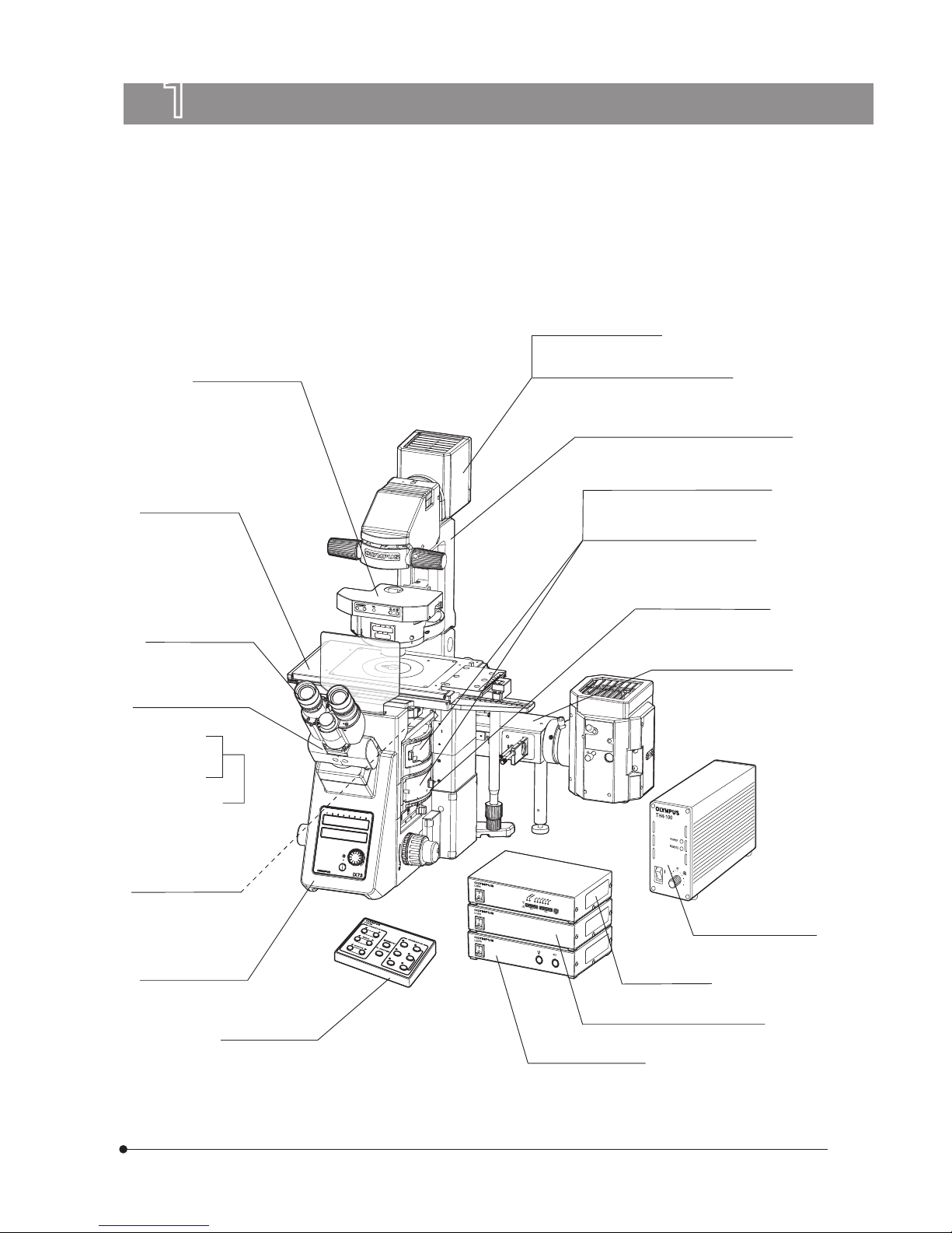
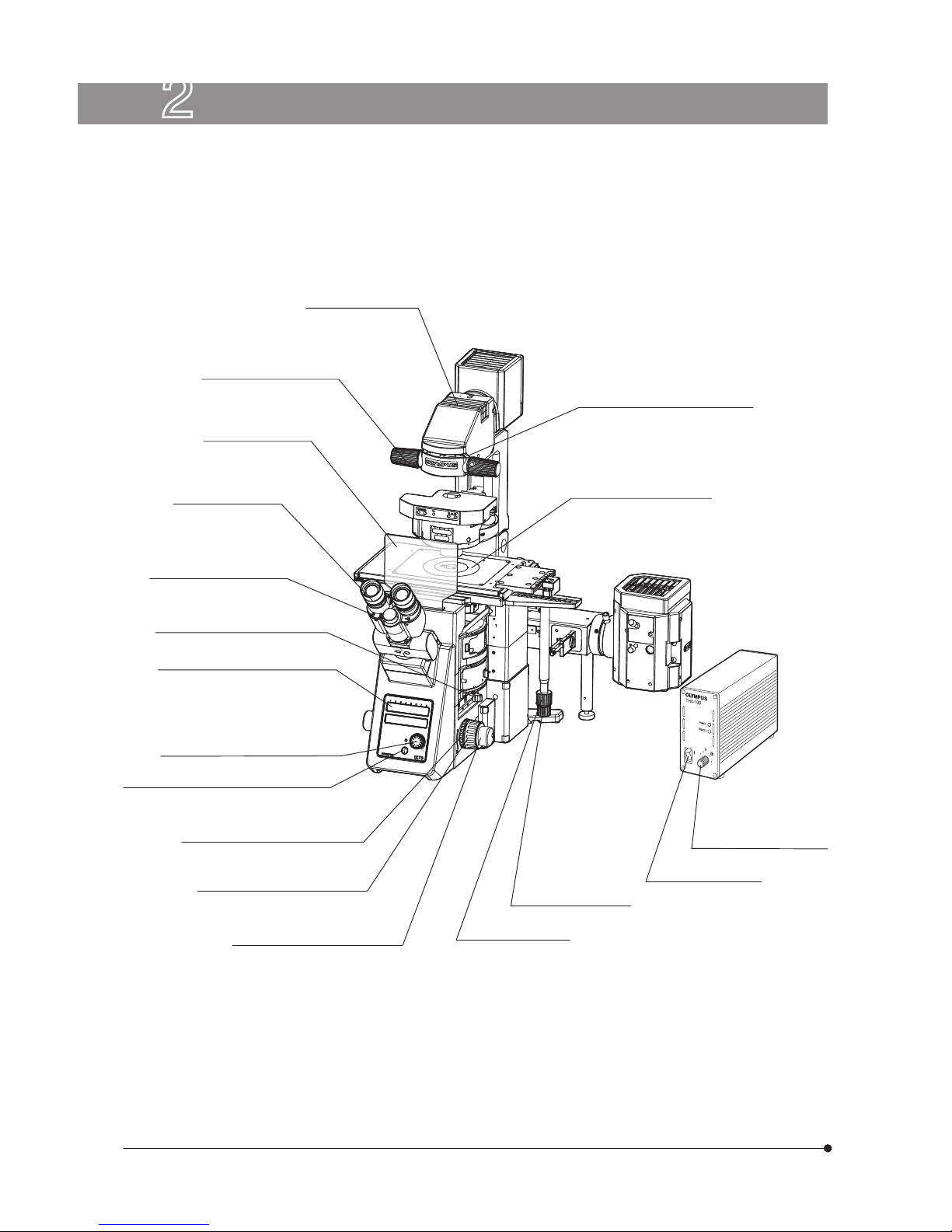
1 MODULE NOMENCLATURE
} Install IX3-CBM, U-CB5S and U-LEDPS on top of the other.
U-LEDPS* # #
LED power supply
LED lamp house
IX3-LHLEDC
8
Stage center plate (p.18)
Detachable.
Main switch (p.14)
} If you have not yet assembled the microscope, read Chapter 9, “ASSEMBLY” (pages 50 to 64).
Filter pocket (p.26)
Condenser height
adjustment knob (p.27)
Diopter adjustment
ring (p.23)
Interpupillary distance
adjustment scale (p.23)
Coarse adjustment knob tension
adjustment ring (p.17)
Coarse adjustment knob (p.17)
Fine adjustment knob (p.17)
X-axis knob (p.21)
Y-axis knob (p.21)
Light intensity control
knob (p.14)
Field iris diaphragm lever (p.27)
2 NOMENCLATURE
Antiglare plate
Light intensity control knob (p.14)
Light path selector lever (p.15)
Transmitted light ON-OFF button (p.14)
Display magnet position
} Paste the magnet accord-
ing to the fluorescent mirror
unit mounted.

9
IX73
Left Side View of Microscope
Other Modules
Left side port
Pre-focusing lever (p.17)
Detachable.
Coarse adjustment knob (p.17)
Fine adjustment knob (p.17)
Motorized LWD condenser
IX3-LWUCDA
Motorized operation button
• TURRET : Switches the turret of
the condenser
• POL : Switches IN/OUT of the
polarizer
• AS \ : Opens the aperture iris
diaphragm
• AS
: Narrows down the
aperture iris diaphragm
Display magnet position
} Paste the magnet accord-
ing to the optical element
attached to the condenser.
Polarizer rotation knob
10
OM1
PO/OM3
PH/OM4
DIC/OM2
BF/OM5
FL/OM6
ATTENUATOR / DIC
IX3
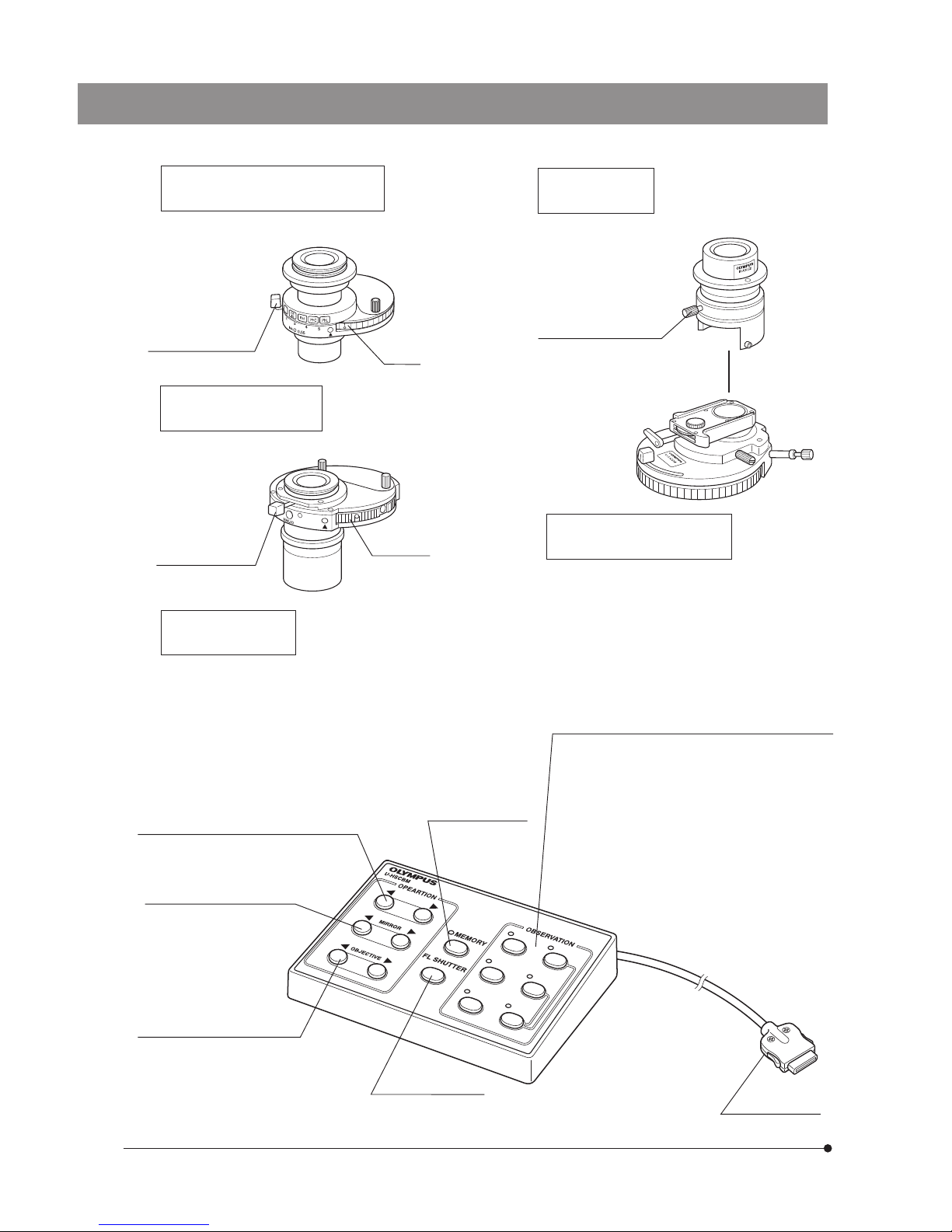
Before use, post the number stickers/indication plates (provided with IX3-CBM).
For details, read the instruction manual for the IX3-CBM/U-HSCBM.
*These buttons are defeated when the coded 6 position nosepiece IX3-D6RES or the coded fluorescent mirror turret
IX3-RFACS is used.
Attenuator / DIC button
For use in switching of the filters.
Mirror button*
For use in switching of
the mirror units.
Objective button*
For use in switching of objectives.
Memory button
FL Shutter button
Observation button
· DIC: Differential interference contrast observation
· PO:
Polarized light observation
· PH:
Phase contrast observation
· BF: Brightfield observation
· FL: Fluorescence observation
· OM1 to OM6: Buttons used to change the
observation mode by connecting to PC and
operating Software cellSens.
The observation mode is assigned to the button
by Software cellSens.
Connector
LWD Universal Condenser
IX2-LWUCD
UCD-Adapter
IX-ADUCD
ULWCD Condenser
IX-ULWCD
} This is a manually controlled condenser.
} This is a manually controlled condenser.
} This is a manually controlled condenser. Refer
to the separate instruction manual for details.
Turret
Turret
Condenser height fine
adjustment knob
Aperture iris
diaphragm lever
Aperture iris
diaphragm lever
Universal Condenser
U-UCD8
Hand Switch
U-HSCBM
Note: Digital images captured by cellSens are not intended for clinical diagnostic use.

11
IX73
Light intensity control knob
Main switch
POWER LED
REMOTE LED
} The applicable halogen bulb is the 12V100WHAL-L.
For details, refer to the separate instruction manual.
Manipulator mounting
screw holes
M6 screw (x 6)
IX-MVR mounting
screw holes
(On both sides)
Plain Stage
IX2-SP
Mechanical Stage
IX-MVR
X-axis knob
Y-axis knob
Y-axis knob
X-axis knob
Mechanical stage with right handle
IX3-SVR
Halogen Lamp Power Supply Unit
TH4
12
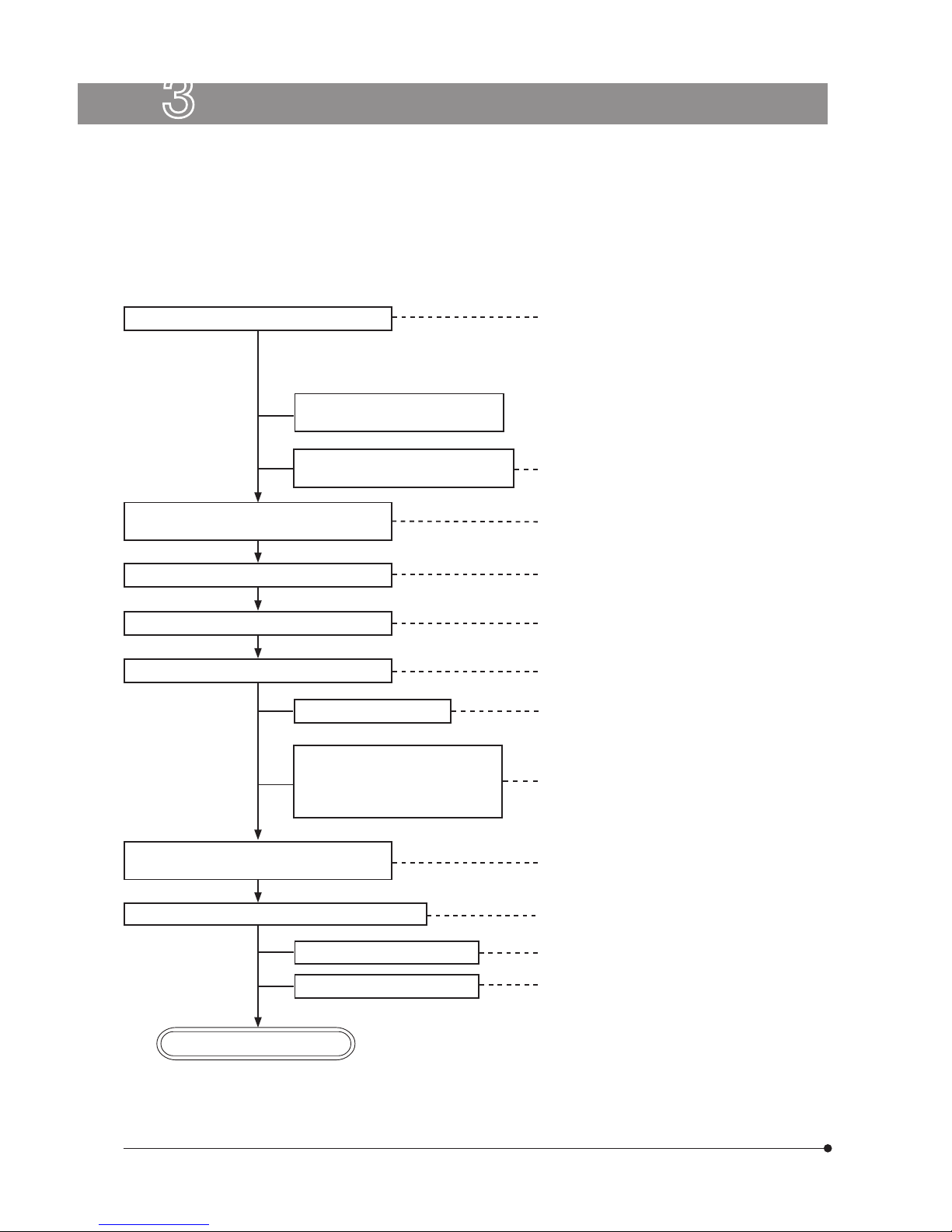
} The following flow shows the operating procedure for the transmitted light brightfield observation which is the basic
observation method of this microscope. The operating procedures for phase contrast observation and DIC observation will be described separately in Chapter 5, “OTHER OBSERVATION METHODS” on page 33.
For the fluorescence observation, refer to the separate instruction manual entitled “ Manual / Motorized Reflected
Fluorescence System”.
Set the main switch to “ I” (ON).
Place the specimen on the stage.
Engage a 10X objective in the light path.
Bring the specimen into focus.
Engage the objective to be used in the light
path and bring the specimen in focus.
Adjust the aperture iris and field iris diaphragms.
Disengage the DIC slider and
analyzer from the light path.
Engage the filters to be used in the
light path.
Adjust the interpupillary distance.
Adjust the diopter.
Adjust the light axis.
Adjust the brightness.
Start observation.
(Controls Used) (Page)
2 Lamp ON-OFF button: ON (p.14)
4 Filter pocket (p.26)
7 Filter pocket (p.26)
@ Main switch: “ I” (ON) (p.14)
3 Light intensity control knob (p.14)
Select the (observation) light path with the
light path selector lever.
5 Light path selector lever (p.15)
6 X-axis and Y-axis knobs (p.21)
7 Revolving nosepiece
8 Coarse/fine adjustment knobs (p.17)
Adjust the brightness.
3 Light intensity control knob (p.14)
3 Light intensity control knob (p.14)
d Field iris diaphragm lever (p.27)
c Condenser centering knobs (p.28)
b Condenser height adjustment knob (p.27)
a Diopter adjustment ring (p.23)
9 Binocular observation tube (p.23)
7 Revolving nosepiece
8 Coarse/fine adjustment knobs (p.17)
e Aperture iris diaphragm lever (p.30)
d Field iris diaphragm lever (p.27)
Engage the required filters.
3
TRANSMITTED LIGHT BRIGHTFIELD
OBSERVATION PROCEDURE
} After turning ON the main switch of the
module to be used, turn ON the main
switch of IX3-CBM at last.
} When you turn OFF the power, turn OFF the main switch of IX3-CBM first and then turn OFF the main switch of the
other modules.7

13
IX73
} Make a photocopy of the observation procedure pages and post it near your microscope.
a
d
e
12
3
4
5
7
8
b
c
3
2
3
6
9
14
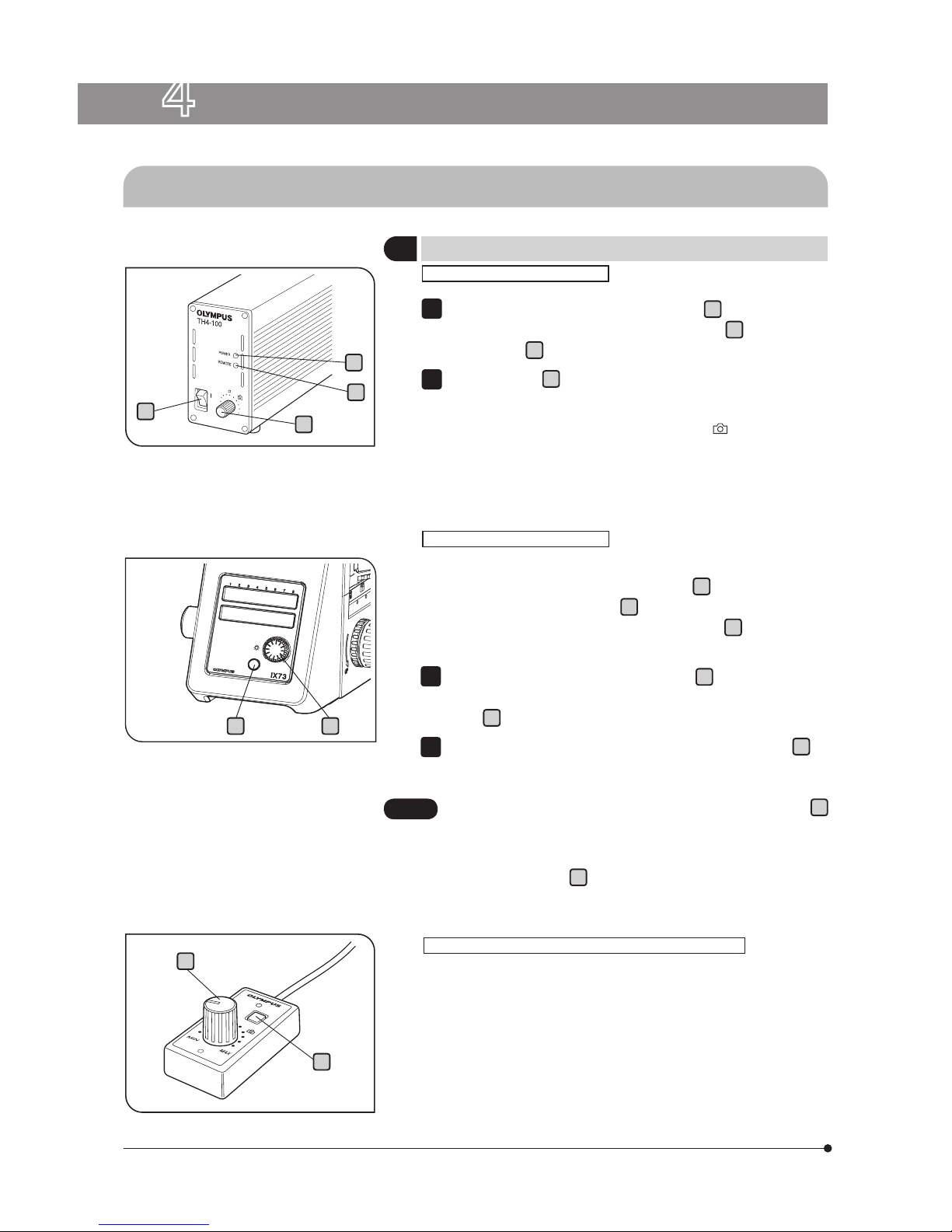
4-1 Power Supply Unit and Microscope Frame
With the TH4
Make sure that the light intensity control knob
a
is in the MIN (mini-
mum intensity) position and set the main switch
b
to “ ON ”. (The
POWER LED
c
lights up.)
Rotate the knob
a
toward MAX (maximum intensity) to increase the
intensity and the illumination brightness.
} With the TH4, the position (approx. 9 V) marked
indicates the position where the daylight illumination suitable for photomicrography
is obtained when the 45LBD filter is engaged in the light path.
1
2
With the IX73 Frame
} If the power supply connection cable provided with the microscope
is connected to the TH4 (the REMOTE LED
d
lights in this case),
the light intensity control knob
a
on the power supply unit is
defeated and only the light intensity control knob
e
on the front of
the microscope is available.
Press the transmitted light ON-OFF button
f
(so that the LED is
illuminated) and adjust the brightness with the light intensity control
knob
e
.
To turn the lamp OFF, set the transmitted light ON-OFF button
f
to OFF.
1
2
The microscope is in standby mode when the REMOTE LED d
is lit. Power of about 2.5 W is consumed in this period.
When the microscope system is not be used for a long period,
set the main switch
b
to “OFF”.
CAUTION
When the TH4-HS Hand Switch is Used
} The illumination brightness can be adjusted from the hand switch
in the same way as on the IX73 microscope.
The hand switch is provided with double-sided adhesive tape, so it
can be adhered to an easy-to-use position.
4 USING THE CONTROLS
1
Turning Power On, Adjusting the Brightness
b
a
c
d
ef
e
f
15
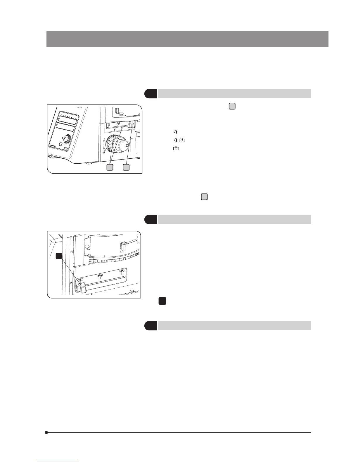
IX73
} The light path selector lever a allows for light path switching
between the observation and left side port paths.
Eyepiece / Camera (Left side port)
100% / 0%
50% / 50%
0% / 100%
} If acquiring the image by setting the light path as [Eyepiece 50%/
Left side port 50%], the light such as fluorescent lamp may enter
from the eyepiece to be reflected in the acquired image.
} Attaching the M4 screw provided with the microscope to either one
of screw holes
b
allows switching the light path in 2 levels.
Use the coded intermediate magnification changer IX3-CAS to
switch the observation magnification in the following 3 levels according to the objective lens magnification.
· 1X
· 1.6X
· 2X
For the assembly procedure, refer to page 54 .
Change the magnification by operating the changing slider.
1
2
Light Path Selection
3
Coded intermediate magnification changer IX3-CAS
} This is the module for clamping the microscope onto an antivibra-
tion platform. The applicable anti-vibration platforms are the following four models.
· 25 mm pitch and 50 mm pitch anti-vibration platforms.
· 1-inch pitch and 2-inch pitch anti-vibration platforms.
For the assembly procedure, refer to page 61
4
Frame Fix Plate IX3-FP
b a
1
16
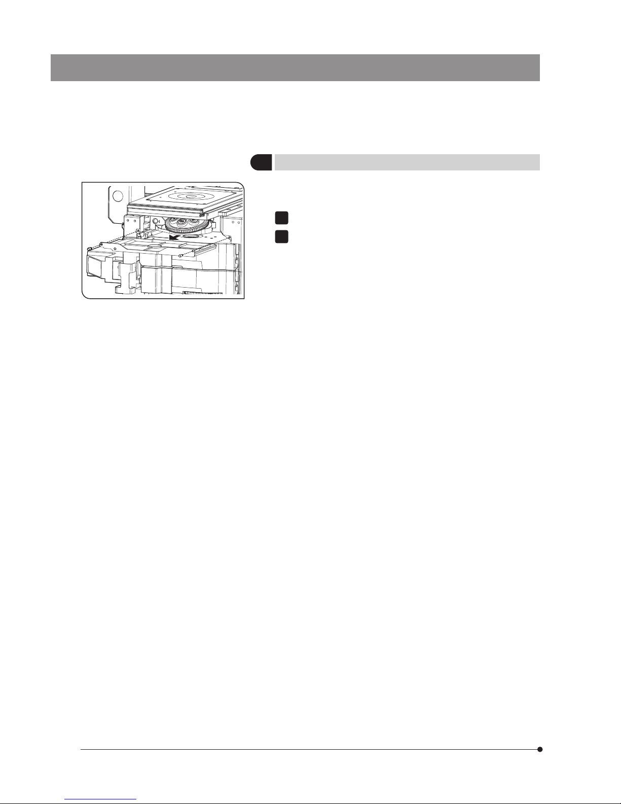
} This tray prevents dust, etc. from falling into the microscope.
Remove and clean it on a regular basis.
Rotate the fixing screws (2 pcs.) to remove them.
Slide the dust tray to remove it.
} Wash the dust tray with water and wipe it with the dry cloth to dry
well before attaching it to the microscope.
1
2
5
Dust tray
17
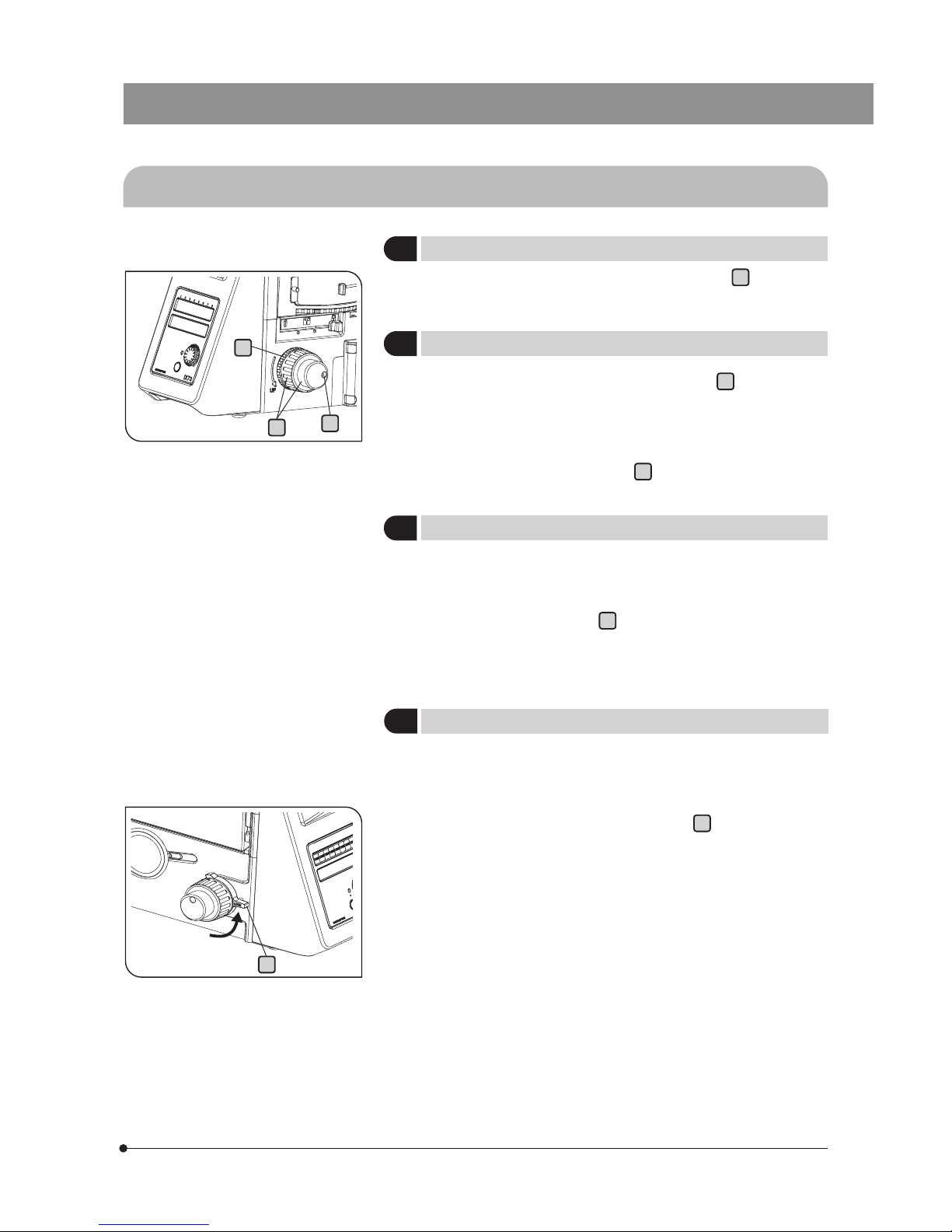
IX73
4-2 Focusing Block
} The fine adjustment knob is designed detachable in order to
prevent interference between the knob and the operator’s hand
manipulating the X- and Y-axis knobs.
· Loosen the clamping screw
c
using the Allen screwdriver provided
with the microscope and remove the fine adjustment knob.
· After detaching, the fine adjustment knob is hollowed to facilitate
manipulation with a fingertip.
} Rotating the coarse or fine focus adjustment knob
a
toward the
front (in the direction of the arrow) raises the objective and toward
the rear (opposite direction) lowers the objective.
} The pre-focusing lever prevents collision between the specimen
and objective and simplifies the focusing operation.
After bringing the specimen into approximate focus with the coarse
adjustment knob, turn the pre-focusing lever
d
in the direction of the
arrow to lock it. Hereafter, the upper limit of the coarse adjustment will
be limited at the position where the lever is locked.
When bringing a specimen in focus, approximate focus can be obtained by simply raising the coarse adjustment to the stop position
so all you have to do additionally is control the fine adjustment knob.
} The focusing function using the fine adjustment knob is not limited.
} Always use the rotation tension adjustment ring b to control the
rotation tension of the coarse adjustment knob.
The tension of the coarse adjustment knob has been pre-adjusted
to optimum tension, but this can be changed as required. Turn the
rotation tension adjustment ring
b
in the direction of the arrow to
decrease the knob’s tension and in the opposite direction to increase it.
4
Pre-focusing Lever
3
Detaching the Fine Adjustment Knob
2
Adjusting the Coarse Adjustment Knob Tension
1
Rotation Direction of the Coarse/Fine Adjustment Knobs
c
a
b
d
 Loading...