

Olympus IX70 Operation Manual
UC BSD Light Microscopy Core Facility Vytas Bindokas, Director
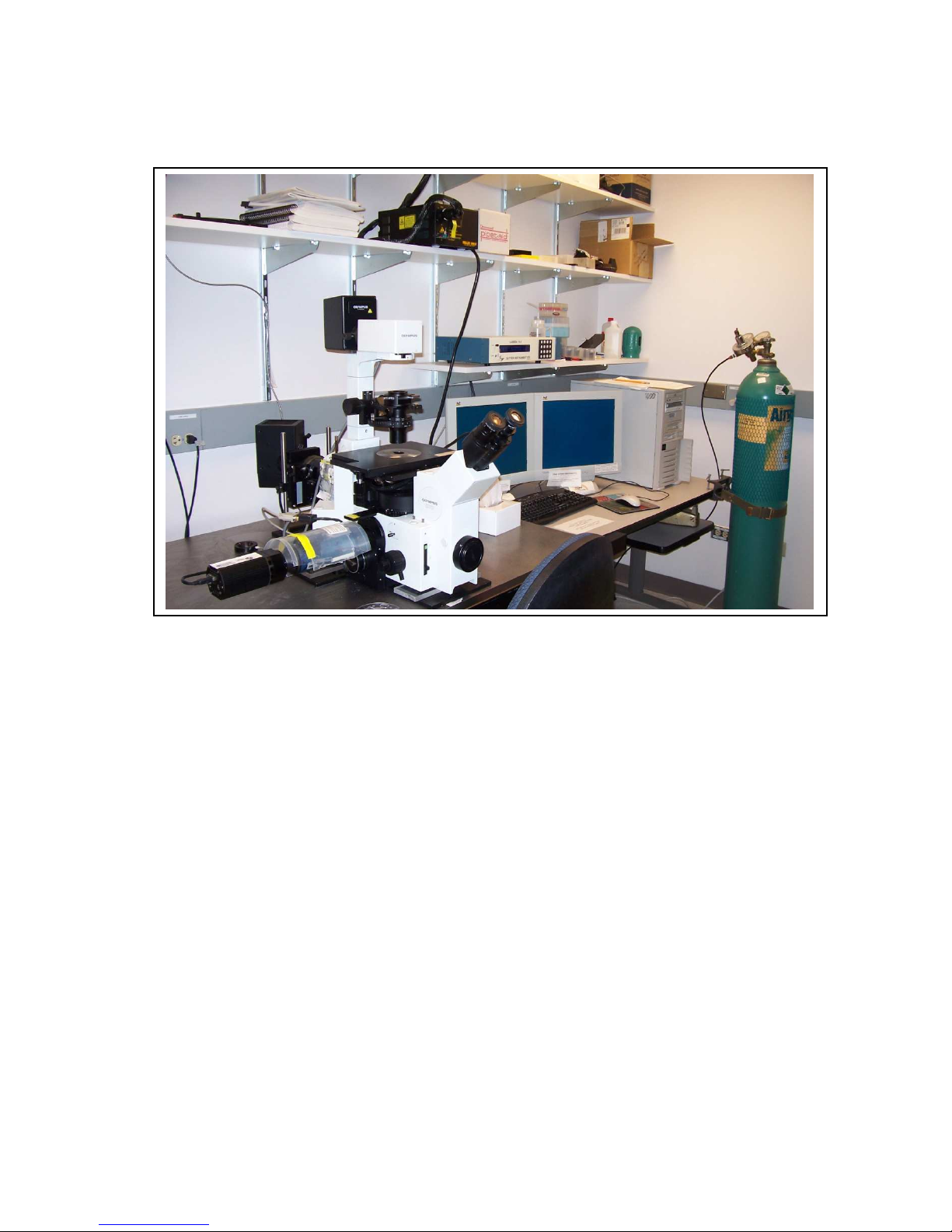
Olympus IX70 Multi-parameter Fluorescence Microscope
Operations Manual (version 1.0 February ‘09)
The IX70 microscope is a manual stand with the ability to collect multi-color fluorescence, differential
interference contrast (DIC) and total internal reflection fluorescence (TIRF), as well as provide optical
sectioning (z-axis stepping) and time lapse imaging. It is equipped with a high sensitivity, high resolution
chilled CCD camera, a green/red or blue/red emission beam splitter for simultaneous two color capture
and MetaMorph + MetaFluor software to control the system.
Examples of types of images that can be captured range from simple image capture (bright field or
fluorescence), sequential capture of up to 4 fluorescent probes, time lapse imaging, (relatively) high speed
imaging, CFP-YFP FRET studies, ratiometric indicator dyes such the calcium probe Fura-2, etc.
Software provides a wide range of image capture and image processing capabilities. MetaFluor is
optimized for real-time (ratio) image capture with real time region of interest (ROI) intensity/
ratio/calibrated data display. MetaMorph is a more general image capture, processing, morphometry
package. Both packages allow images to be automatically collected and annotated.
PDF Created with deskPDF PDF Writer - Trial :: http://www.docudesk.com

Turning on the System
1) fire the arc lamp under the microscope table
(make sure nothing else is on)
#1
always!
2) turn on the brightfield bulb power
switch on the microscope base (#2)
#2
#3
3) turn on the filter changer box (#3)
4) power up the computer (#4)
5) ONLY if you are using TIRF, fire the Ar laser
#4
#5 for TIRF
ONLY
6) log on and start either MetaMorph or MetaFluor
7) write down your start time on the log sheet
Shutting down the System
The arc lamp must be on for at least 20-30 min prior to turning it off, you must wait that long before
turning it back on, too. Firing the arc greatly shortens the lamp life, so it’s best to leave it running during
the day when the schedule shows other users are coming—check the schedule, the last person MUST shut
down the system.
If there is another user after you:
1) Clean any oil or water immersion objectives you used during your session.
2) Log off from your Windows session
3) If you used the TIRF laser (#5), turn that off; leave everything else (microscope and computer) on.
4) Write down the time on the log sheet.
If you are the last person scheduled:
1) Clean any oil or water immersion objectives you used during your session.
2) Log off your Windows session, then do another cntl-alt-del and choose the SHUTDOWN button.
3) Turn off the TIRF laser (#5) if used, the filter changer box (#3), brightfield power (#2), and the arc
lamp (#1).
4) Cover the scope with the plastic cover.
5) Write down the time on the log sheet (how else will the next person know if system is cool
enough to restart?)
2
PDF Created with deskPDF PDF Writer - Trial :: http://www.docudesk.com
System Anatomy
Brightfield power switch
Brightfield
button and
DIC shear
The IX70 microscope is a manually operated microscope with automated digital image capture. The
objectives, emission filter cubes, DIC prisms, and focus are all controlled manually. Image capture and
excitation filters are controlled through the software.
Objective turret
adjustment screw
Filter turret
intensity slider (on front left)
Viewport knob
(on back of base)
3
Focus knob
Fig. 1 Controls on microscope base
To change the magnification, first lower the objectives by focusing the turret all the way down
with the focus knob (so as not to disturb the sample or bash the objectives into the stage). Then turn the
turret from the base. The objectives are arranged clockwise in order of increasing magnification. Be
aware that when you change the objective MetaMorph will not register the change unless you choose the
magnification from the taskbar as well, making scalebars and measurements incorrect.
We now have more objectives than positions in the nosepiece. Objectives listed below as
Available are not normally kept on the microscope but are available for use, just ask the staff to put it on
for you. DO NOT try to change objectives yourself. We must enforce the China Shop Rule of “you broke
it, you bought it”… Dropping a lens is very bad. NA refers to Numerical Aperture, the resolving ability of
the lens; bigger NA = higher resolution.
Available 2x/NA0.04 dry. This lens yields a field of view over 5mm and yields useful
fluorescence images for very large preps. The brightfield condenser will require defocus (upwards) to
PDF Created with deskPDF PDF Writer - Trial :: http://www.docudesk.com
produce illumination over the entire field of view. Be careful when trying to focus this lens on materials
Fig. 2 right side of scope
high above the stage—you may cause the high power objectives to push up on the stage plate/specimen
and risk damage to optics. Ask for advice on how to use this lens.
Available 4x/0.16 dry.
10x/0.3 dry
20x/0.5 dry. NOTE this lens has 3 correction caps available to improve images through #1
coverslips, 1-mm thick glass dishes (or a glass slide), and also for plastic (1.1-mm thick). Caps are
unscrewed and replaced with the desired cap. Be sure to place the cap in a plastic holder; holders are
located on the shelf to the right of the scope). Note this lens has poor performance in UV (lousy DAPI
signal).
40x/0.6 LWD dry objective. This has a correction collar for glass/plastic and thickness (0-2 mm).
(not on scope routinely; place into 40x oil position when needed).
Available 40x/1.35 oil UV-optimized. This is a very high resolution objective the best for use
with UV dyes, especially the calcium dye, fura-2. Moderate magnification and high NA make this an
especially bright objective.
60x/1.45 oil, TIRF. The very high NA produces the highest resolution under regular epi
fluorescence. This objective is also optimized to permit the specialized illumination method called Total
Internal Reflection Fluorescence (TIRF; AKA, evanescent wave). TIRF uses laser light to illuminate only
the footprint of a cell attached to a glass coverslip (i.e., the bottom 40 to 200 nm), showing nothing of the
portions above that zone. The high NA yields optical sectioning that approaches that on confocal
microscopes.
Available 60x/1.2 water. Use a hanging drop of water, not oil, on this objective. It provides a
greater working distance than the 60-oil, and when viewing thick preparations it minimizes depth-related
optical distortions.
100x/1.3 oil. Not as bright as either the 46x or 60x oil objectives, but still a nice high mag
objective.
Available 150x/1.4 oil, TIRF The Rolls Royce of objectives. This is a high resolution, high mag
objective that can also be used in TIRF applications. You will need to manually calibrate pixel sizes
when you use this lens.
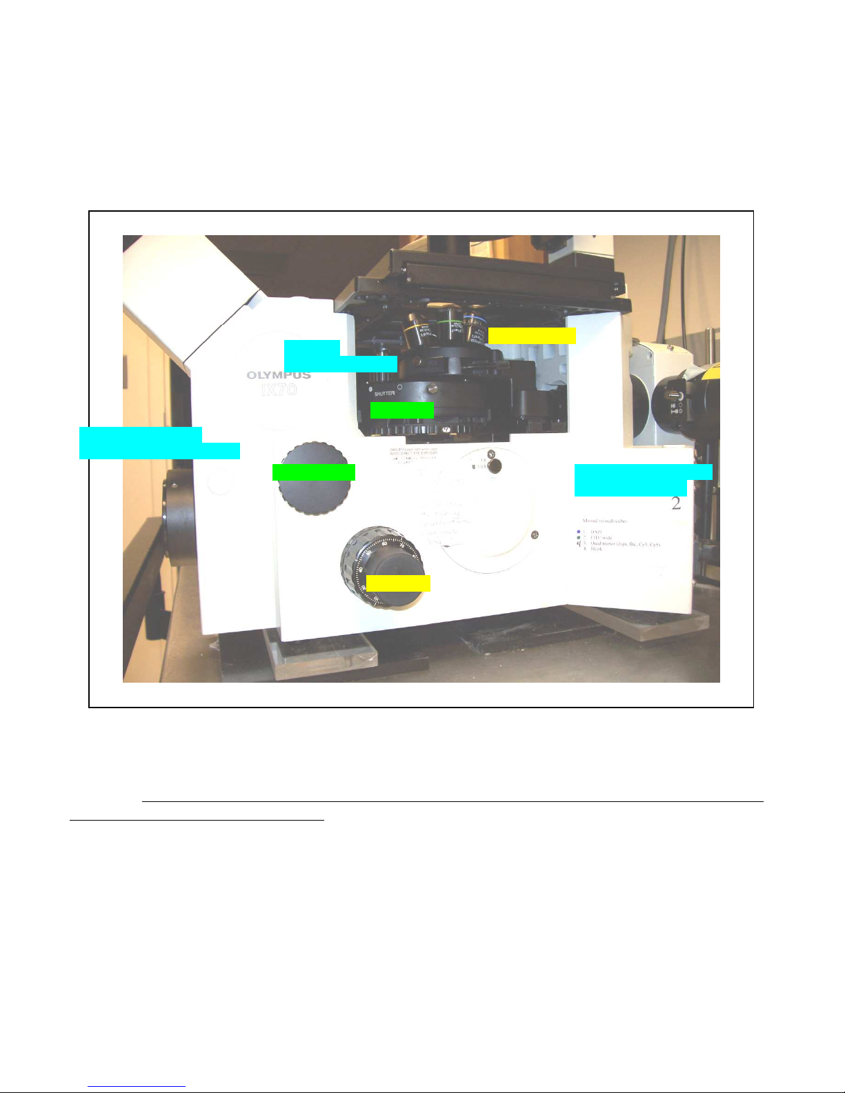
Brightfield and Fluorescence modes
There are four positions for fluorescence filter cubes in the
manual turret below the objectives. The filter position is
changed by rotating the wheel under the objective turret (see
Fig. 2, “Filter change wheel”). We have four cubes
permanently stationed in the turret: DAPI, FITC long pass, the
Quad mirror and Cy3. The DAPI, FITC long pass and Cy3
cubes will work for both the camera and the oculars (they
have both excitation and emission filters built in) but the
Quad mirror works for the camera only!! The Quad mirror
(ID tag= “4”) is for collecting multiple color channels with the
Acquire multiple wavelengths menu in MetaMorph. It will
collect DAPI, FITC (narrow), TexRed and Cy5 channels only
when the appropriate filter button in the taskbar is pushed.
The cube in the light path is indicated by the colored ID tab,
Filter
wheel
Manual
shutter
Filter list
Mag
changer
4
PDF Created with deskPDF PDF Writer - Trial :: http://www.docudesk.com
decoded by the sheet taped to the side of the scope. If you need filters not currently installed, please ask
Field
Centering
P
rism
Condenser
for assistance in swapping out the cubes (we have more choices than available turret positions). A manual
shutter slide is also located on the side (Fig. 2 “manual shutter”). Push toward the wall to block
fluorescence (but be aware this will prevent you from snapping a picture too!). There is a 1.5x tube lens
that will enlarge the image destined for your eyes (see “mag changer” Fig 2). However, the image quality
is poor and a bright reflection renders images in the camera port in need of post hoc corrections. Use the
1-X (pushed in) position for all quality work. A brightfield lamp is available (above the scope) and is
controlled via the square button on the front left-hand side of the scope base plus the voltage up/down
slider (see Fig 1).
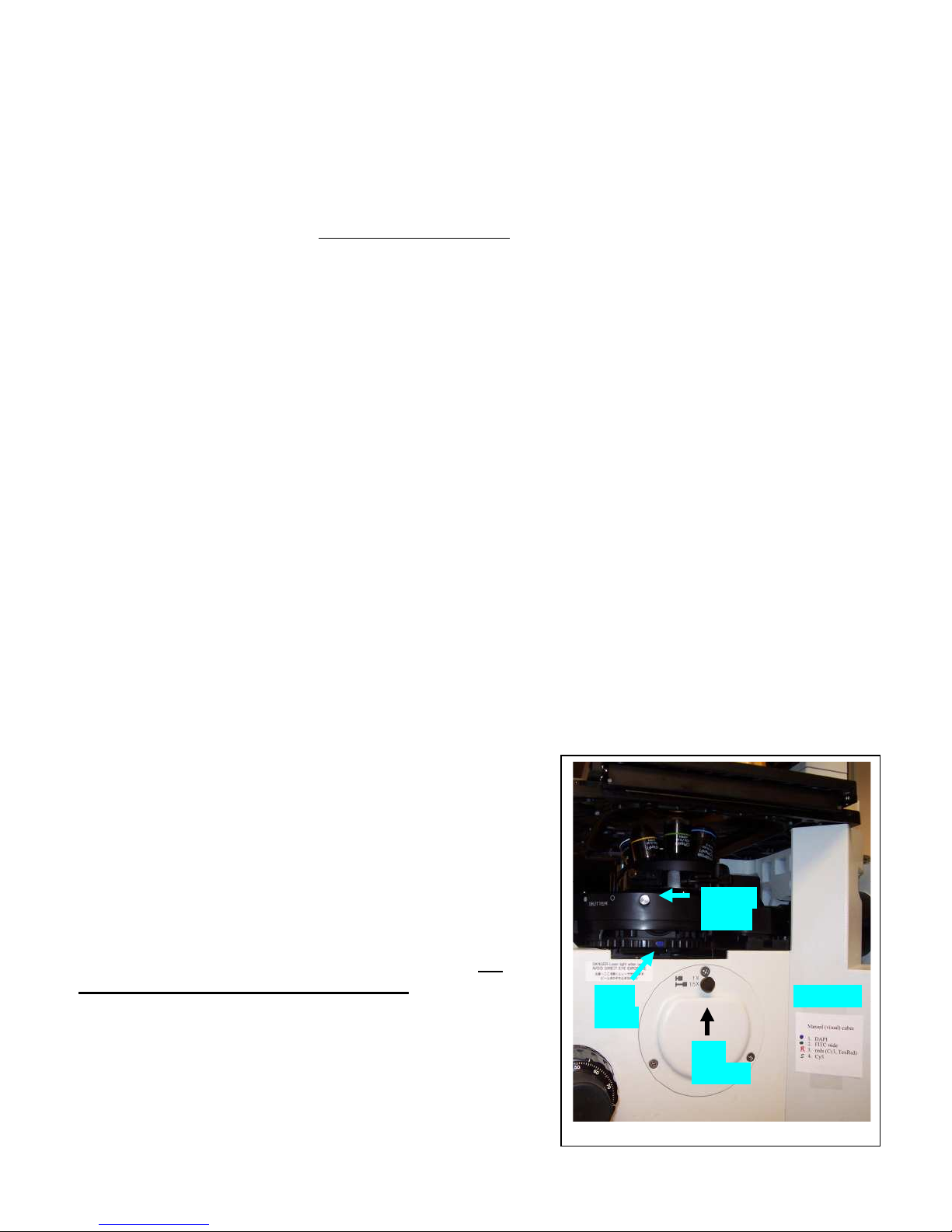
DIC:
The microscope is equipped with Differential Inference Contrast (DIC) optics to generate contrast
in unstained materials. To setup DIC or use is in ocular mode, one needs to use the analyzer slider (must
be inserted under the filter turret) and the optical path should be optimized (Kohler illumination, described
below). The DIC analyzer (polarizer) for image capture is mounted in the emission changer. The visual
DIC analyzer is NOT normally present (i.e., by request) since users tend to leave it in the optical path and
cut fluorescence intensities by mistake (must be pulled out for all work apart from visual work). DIC uses
a pair of prisms, one above the slide, one below. The upper one is found in the wheel on the condenser
(Fig. 3), and should be changed manually to best match the
Brightfield lamp housing
aperture
screws
selection
aperture
Focus knob
Fig. 3 The condenser
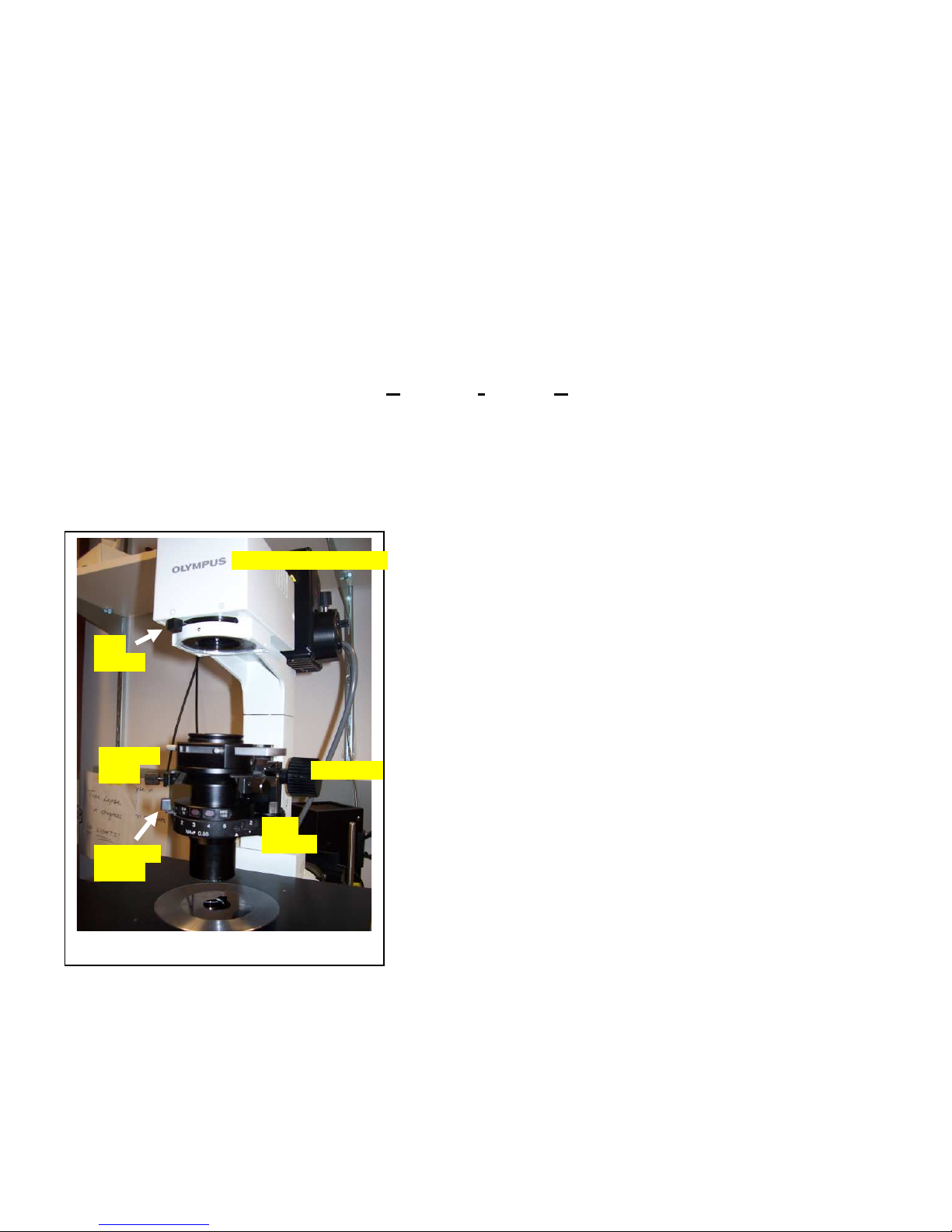
image contrast (at the price of brightness; you will also see more dirt on your slide the more you close it
down).
Note that plastic degrades the DIC effect, and while you may get enough contrast for an image, the
quality is far worse than for cells on a glass coverslip. It is also best to remove the lids from plastic
dishes, especially if there is condensation. A plastic lid with built-in glass window is available. Silicon oil
objective in use. Due to space+cost limitations we have only 3
(upper) prisms: 10x (use for 10x), 40x oil (use for 20x, 40x and
100x), and 60x TIRF/oil (use with 60x lenses). The prisms
match the objectives they are named for, so DIC quality will be
best with 10, 40, 60x lenses, and acceptable with others. The
lower shift prism is constant for all objectives. It has a knurled
screw that allows you change the contrast and apparent
direction of light hitting your sample (also called the shear).
Adjust the screw to get a uniform background and details (see
Fig. 1 “DIC shear adjustment screw”). Before you display the
DIC image, you should optimize the optical path to get the
most even illumination possible. To achieve Kohler
illumination, first find your sample on the slide and make sure
it is in focus. Then focus the condenser onto that plane by
closing the field aperture (Fig. 3) and using the condenser
focus knob to get the sharpest image of the closed iris leaves
(should be a bright hexagon of light). Use the centering screws
(Fig. 3) to center the iris image, then open the field aperture
iris until it just vanishes from view. The iris on the condenser
itself (Fig. 3 “condenser aperture) can be closed to enhance the
5
PDF Created with deskPDF PDF Writer - Trial :: http://www.docudesk.com
6
can also be layered on top of the media to prevent evaporation without image distortion. DO NOT USE
SILICON OIL WITH THE WARNER DISHES! It will ruin the rubber gaskets and cause leaks.
We have added a transmitted light shutter to gain better control of DIC capture and
fluorescence sequences. The brightfield bulb can be turned on with the power switch and button and set
to the desired brightness with the intensity slider, and then controlled with the shutter. The shutter opens
automatically when the DIC button is selected and closes when a fluorescence button is selected or once
an image is collected. There appears some resistance of program control vs. manual microscope control
where you may have to hit the power-on button and scroll voltage up and then try the power button again
to get the lamp to behave (it will perform once you show it who’s boss, I guess; It’s a MM bug. This isn’t
an issue in MetaFluor software).
Fluorescence:
It’s important that no other electronics be powered up when firing the arc lamp; it can
create a power surge that will fry other components (a very bad thing). Since this is a manual microscope,
choices in the software require changes to the microscope that must be made by hand. We have added
pop-up window prompts to MetaMorph to guide you in changing filter cubes, etc. Fluorescence uses
excitation filters to excite your probe(s) with a narrow band of wavelengths, a dichroic mirror to reflect
the excitation onto your sample while allowing the longer fluorescence to pass trough, and a barrier (AKA
emission) filter to block stray excitation light and limit the output color. Most filter cubes use dedicated
excitation and emission (barrier) filters. This is the case with the DAPI, FITC (wide) and Cy3 cubes in
the turret. These filters will work for both the camera and the oculars (by eye or by image). A few cubes
(like fura-2, and the cubes in the “FRET” set) require proper exciters or barrier filters to be set by the
filter wheels (Sutter controller) through the software. These filters also work by both by eye or by camera.
However, the new quad mirror requires the filter to be changed thought the software. It will image DAPI,
FITC (narrow), Cy3 or Cy5, depending on the taskbar button selected, but it will ONLY work through the
camera. You will NOT see anything by eye but a lot of very bright light!! Use the single color cubes to
find your sample and only use the quad if you need Cy5 or if you are capturing multiple wavelengths with
the Acquire Multiple Wavelengths dialog. Regardless of the filters used, it’s highly recommended
that changes of all filter cubes (for the color of fluorescence) be initiated through the taskbar.
To choose a color channel, click the taskbar button for the wavelength you want, then
follow the on-screen prompt or filter list to rotate the manual filter turret under the objectives to the
correct position (see “filter wheel,” Fig. 1 and 2). Press “Continue” on the pop-up window to toggle the
shutter (if necessary). Alternatively, you can learn the settings of the Sutter Lambda 10-2 filter changer
box located to the right of the microscope (long, bottom-most controller with keypad). Be aware that not
setting the exciter or emitter filters correctly can blast your sample, or worse, your poor eyes, with the full
arc lamp output. The Sutter filter changer operates a shutter to
limit illumination to actual image collection (to minimize
sample bleaching and phototoxicity), a high-speed excitation
filter changer, and a high-speed emission (camera-side) filter
changer. {optional reading /details} By default, it is under computer
control (parallel port). Manual mode requires you to press the “Local”
button on the top right of the keypad. Press either “F1” of “F2” to select a
filter changer to command. Note that the shutter is on F1; pressing the
“shutter” will toggle the light on/off. The other keys address the ten filter
positions per wheel (numbered 0 through 9).
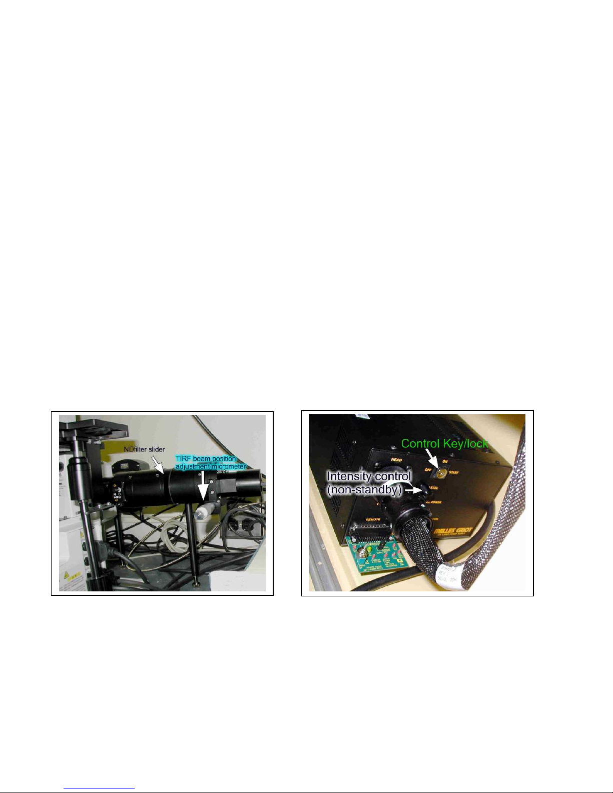
1% slider
25% slider
Fig. 4 Neutral density filters
PDF Created with deskPDF PDF Writer - Trial :: http://www.docudesk.com

Importantly, there are two filter sliders to attenuate light (ND = neutral density filters) one
on the filter changer just in front of the arc lamp housing, and one in front of the filter changer (Fig. 4).
The filter changer (back) slider imposes an ND2 (100x less light, or 1% illumination), and the scope
(front) slider produces 25% illumination. You should use as little light for live cell imaging as possible
(both sliders pushed in) to forestall photodamage. Most imaging can be done with only the 25% slider
pushed in (well suited for your eyes, too). You can use full light for dim samples, but be aware that you
are probably getting high autofluorescence and probes will bleach quickly. And remember to always
check your controls with the same illumination intensities!
Position Whl A (F1)
(excitation)
0 Closed Open
1 Open 450/65
2 340 485/40
3 380+nd1.0 535/30
4 440/20 polarizer
5 480/40 colorRED
6 560/40 colorGRN
7 640/20 colorBLU
8 Open 630/60
9 Open 682/22
Whl B (F2)
(emission)
following chart reports the contents of the 10 filter slots in each wheel:
The Whl-A 340/380 positions are used to conduct calcium imaging
studies with the indicator fura-2. The 440 exciter and Whl-B 485/535
emission filters are used for real-time FRET probes such as cameleon
sensors. Both of these methods will require the proper dichroic mirror
(filter cube) to be placed into the microscope (not routinely installed at
this moment). We are swapping them to the #3 filter cube position since
few high-speed studies require combinations of fura-2 plus FRET plus
DIC. ColorRED is (600nm LP), colorGRN (500-575 BP), and
colorBLU (500nm SP) filters are intended for (additive) RGB color
capture, but can be used in custom filter designs as well.
{optional details} For those who want to know the details, the
Need special filters? Ask the staff about them… we have more filters than turret positions, so CFP, YFP,
Chameleon FRET, FURA, TexRed and Cy7 cubes are available but not installed.
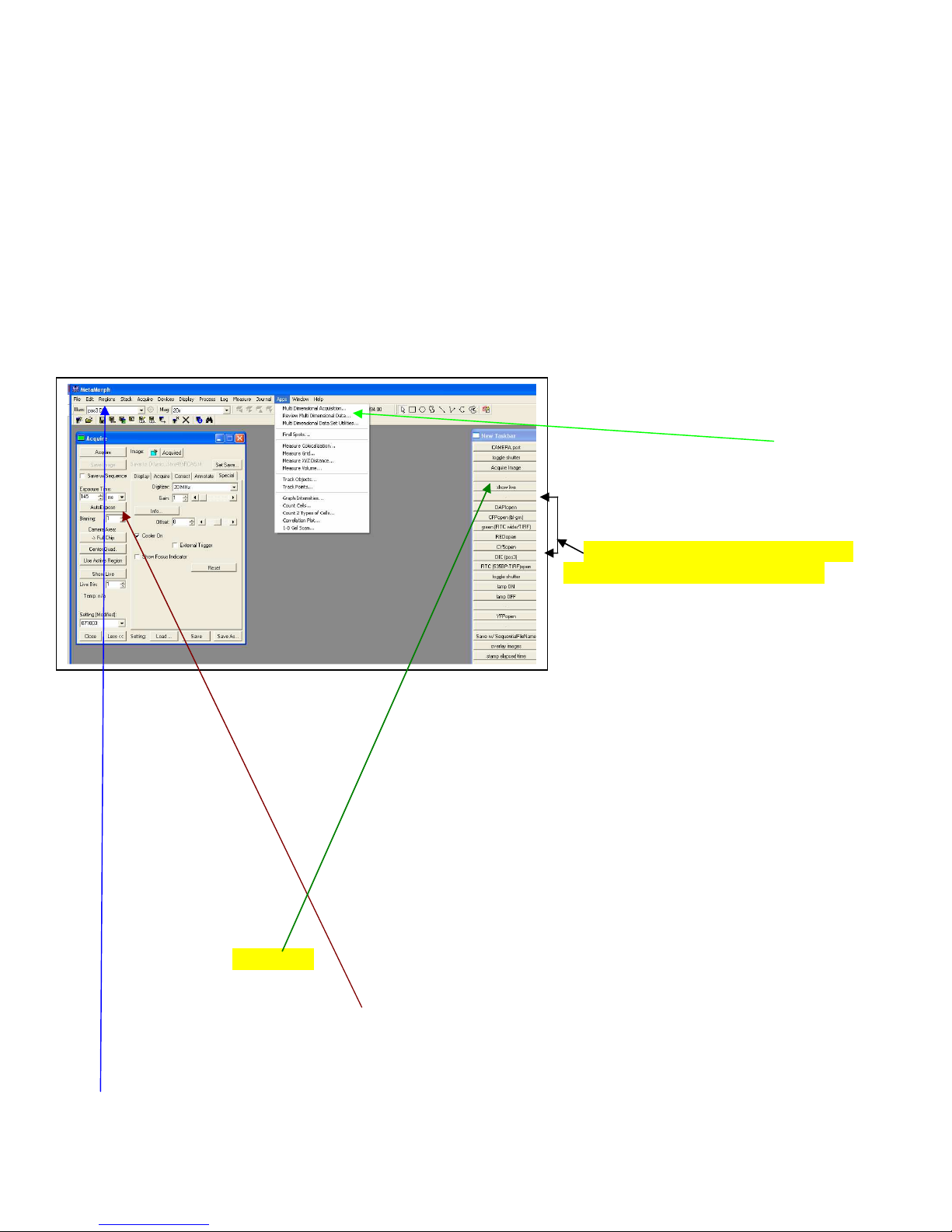
How-To Do (non-ratio) Fluorescence Image Capture
Much of the configuration of the microscope is manual, but the software will queue you
with pop-up windows to change what needs to be changed by hand. Turn on the computer and logon; start
MetaMorph. MetaMorph (see Figure below) is configured to always start with the 20x objective in place
and cubes set to DIC. The software will pop up a window reminding you to change the objective to the
20x to start. The TASKBAR that pops up contains most of the buttons to select an objective, rotate in
filter cubes, select light paths, operate the camera, etc. If the taskbar does not open, you can find it under
Journal Taskbars Load Taskbar. Choose the “main” taskbar. When you choose a function on the
taskbar, a small window will pop up to
tell/remind you if you need to change
something manually.
1) You should always use the main menu
(top bar) to open the ACQUIRE acquire
menu. This menu gives you access to
camera controls. Other ACQUIRE menu
options include acquisition of multiple
wavelengths, Z series, timelapse, etc. Many
of those menus close after you use them, so
you’ll have to go back and re-open them for
more data. If you are collecting multiple
7
PDF Created with deskPDF PDF Writer - Trial :: http://www.docudesk.com
8
fluorophores, you can make the task easier by using the Acquire Multiple Wavelengths menu. This
automates collection of up to 6 “channels” of data, each stored with a fixed/different exposure (or
autoexposure). To use the Acquire multiple wavelengths menu, pick the number of probes to collect and
assign the identity and order in the lower section. Pressing the upper right camera icon collects the entire
sequence and stores it in one memory stack. For this to work, the microscope has to be set up with the
quad mirror in place in the lower filter turret. If you want to use the individual color cubes and change
cubes between captures, pressing the cameras next to each probe collects only that probe. To collect color
(histology) images, make sure the order is colorRed. colorGRN, colorBLU. Gain is assigned from the
main “acquire” window and is applied to all channels. Independent exposure times can be assigned by the
user or calculated for every capture by checking the “autoexpose” box. Autoexposure takes time since a
series of exposures are tried and evaluated. You may want to disable the auto feature after the first pass
and used fixed times thereafter. You certainly do NOT want to autoexpose everything if you doing a study
where staining intensity is important
(e.g., treatment vs control). If you want
to time-lapse this sequence and/or do a zaxis collection, then use the APPS menu
routine Multi Dimensional Acquisition.
Again, for multiple wavelengths, the
quad mirror cube must be used in the
filter turret.
2) Pick one of the illumination settings
from the taskbar (2-column menu).
There are two columns: the righthand
side is all buttons that work with the
“quad” mirror (camera only). Change
the manual filter turret to position 4 and
flip through the channels with these
buttons. The lefthand side is all buttons for the single color cubes (use for either oculars or camera).
Pushing one of these buttons will pop up a window to tell you which cube to position in the bottom filter
turret and then “Continuous” on the pop up window will open the shutter. You will be able to scan for
your sample with one of these cubes, but be sure the light path is set to EYE (check that the knob on the
right-hand side of the scope is set to the eye image). If it set to camera (SP, or the icon for the non-existent
manual camera) rotate the wheel until it clicks and you see the eye. Focus upwards (CCW, ‘fingertips up
= up’) to find your samples, but keep in mind there is NO limit in place to prevent you from crashing into
things and breaking your prep, or worse, an objective. If you are having trouble here, ask for help.
Unstained cells may be easier to find with DIC, but I prefer to use fluorescence mode for stained
materials. If you have a DAPI stain, this works particularly well.
3) Find the cell(s) you wish to image and place them just to the right of center. The camera sees roughly
the center/right 50% of what you see. You should then verify that the camera sees the same focus that you
did by pressing the “Show Live” taskbar button (middle left column)—this reminds you to change the
light path by rotating the knob to the “SP” side port setting and then starts the camera+screen display.
You can use the Acquire menu “autoexpose” button to set the brightness (this can take some time with
dim samples), or enter numbers directly. With no binning and gain=1, 100-200 msec should give a decent
image (on average). (exposure testing is set to max out at 10 sec). If there is no image on the screen,
double check that you remembered to send light to the camera. Note: There are pulldowns at the top that also
allow you to change “illuminations” and objectives. Be aware that these menus do LESS than the similar buttons in the taskbar.
Changing a filter, for example, only tells you to change the filter, while the task button would also then open the shutter…
PDF Created with deskPDF PDF Writer - Trial :: http://www.docudesk.com

Troubleshooting Guide:
• No Image by eye, no illumination of slide. If there is no illumination when using the software to
open a filter setting (verify by looking at slide), check to see that you have turned on the mercury arc
power (be sure to power down all electronics before firing it, if this is the case!); 2) check that the
Sutter controller is turned on (turn on); 3) check if the fluorescence/TIRF plunger (behind scope, see
picture on pg. 11) is pulled UP to the fluorescence position. 4) Are too many ND filter sliders pushed
in? Try with only the 25% ND slider in, Fig. 4. 5) Is filter turret (manual) shutter closed? Pull toward
you to open. 6) Is the filter cube seated properly? Try turning the manual filter turret wheel and see if
it settles in. 7) Is there an objective lens in the position you are using?
• Ugly image, but looked OK by eye? 1) Check the Display/AdjustDigitalContrast menu to see if the
parts and squint at brights). You can also set display color here. Camera data is 12-bits (4095
brightness values), the computer display is 8 bits per color (255 levels), our eyes see less than 100
shades per color. So you have much ability to manipulate displays. You want to use the same settings
for controls vs. treatments. Also, while
MM will correctly restore any settings you
save to images, most other software will
not use this custom information. (Use the
Edit/Duplicate/AsDisplayed menu to
create an exact likeness for other
applications). 2) check the display
scaling range (two ways to do this). While
it’s useful to use autoscaling to find focus,
it won’t actually give you an idea of how
bright the data actually is (for this, see the
live histogram along the side of each
image). Using big values to control
(autoscale) display mapping can make the
image really look wrong! (use 0.0 or 0.1,
0.1). Using a fixed range (0 to 4095 is full
range) works until the sample gets too
dim. The Display/ScaleImage menu gives
you display mapping range control too,
last user has left some strange setting.
Note the RESET button—press it to undo any custom display values. You can
check/uncheck the “use display settings
for activated images” box to control
display of data. This tool only affects
the appearance of the data, NOT the
data itself. Images will not save with
these settings. You can use the
GAMMA slider to (nonlinearly)
emphasize the bright or dimmer parts of
the image. Using a gamma=1.3 or so
tends to make the data look more like
what our eyes see (we favor less bright
9
PDF Created with deskPDF PDF Writer - Trial :: http://www.docudesk.com
10
and also allows you to directly enter the same display ranges for images meant to be shown
identically. There is a taskbar menu item (top Right-side Column) that forces displays to full range
(“scale12bits”). The “autoscale” taskbar button reverts/sets autoscaling. 3) Did you use the taskbar
“Show Live” button? This activates the camera+screen display; the Acquire/Acquire menu ‘show live’
ONLY starts the camera. You still need to direct light to the camera vs eye path. 4) Try an
autoexposure. If you are collecting too few intensity values, the image will look grainy. If screen is
solid color, you are probably too bright. Use the autoexposure button. If you didn’t send light to the
camera, it will stop trying after testing a 10-sec exposure maximum (hit ESC key to abort an
autoexposure). 5) Press the “Full Chip” button to make sure you are getting the full image vs some
tiny portion no longer applicable.
Total Internal Refection Fluorescence (TIRF)
SAFETY FIRST! Know all operating procedures before attempting TIRF! TRAINING IS MANDATORY!
Total Internal Reflection Fluorescence Microscopy (AKA evanescent wave) uses laser light to
create a narrow band of excitation limiting the view of fluorescent materials to the space immediately
above the glass coverslip. The depth of illumination can be 90-200nm thick, a region that limits your view
to just the cellular contact to the glass. It allows you to view the cellular footprint and can be used to
obtain high-speed images of changes in surface membrane, especially exo/endocytosis. It requires a laser
spot be aimed at a critical location in the objective so as to bounce the light off the glass/water interface.
This optical slice is more narrow than a confocal, but is limited to the space just above the cover glass.
You must use the special 60x, 100x or 150x oil objectives to obtain the critical beam angle (via the high
NA). You can use regular glass coverslips and regular oil with these lenses.
Since this technique uses laser illumination, you MUST have special training.
Laser safety is important; why risk damaging your retinas??
The laser source is a 10mW argon laser producing a 488nm beam. The laser is activated by rotating the
key beyond “on” to “start” and releasing the key. It begins to produce light10 to 60 sec after activation.
Select the laser illumination path by pushing the slider (behind the scope, see pg. 11) down. The beam can
be moved to the critical angle by rotating the micrometer screw counterclockwise (above, right).
Clockwise rotation moves the beam to the center of the objective, the non-TIRF position. Be sure to use
the TIRF filter cube (called “green FITC wide/TIRF”) in the software. This is a long-pass FITC set that
PDF Created with deskPDF PDF Writer - Trial :: http://www.docudesk.com
 Loading...