

Page 1
INSTRUCTIONS
IX71/IX51
INVERTED RESEARCH MICROSCOPE/
INVERTED BASIC MICROSCOPE
This instruction manual is for the Olympus Inverted Microscopes Models IX71 and IX51. To
ensure the safety, obtain optimum performance and to familiarize yourself fully with the use
of the microscope, we recommend that you study this manual thoroughly before operating
the microscope. Retain this instruction manual in an easily accessible place near the work
desk for future reference.
A X 7 3 1 9
Page 2

Page 3

IX71/IX51
CONTENTS
ect assembly and adjustments are critical for the microscope to exhibit its full performance. If you are going to
Corr
assemble the microscope yourself, please read Chapter 9, “ASSEMBLY” (pages 55 to 65) carefully. For the modules
provided with instruction manuals, also read the assembly procedures in their instruction manuals.
IMPORTANT — Be sure to read this section for safe use of the equipment. —
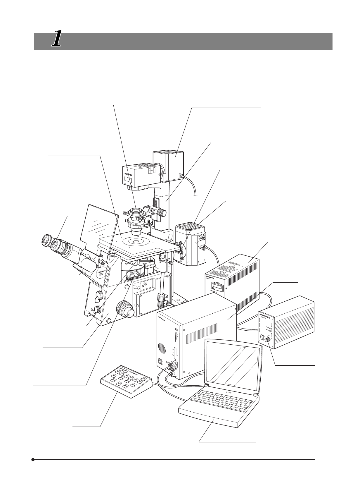
1 MODULE NOMENCLATURE
2 CONTROLS
TRANSMITTED LIGHT BRIGHTFIELD OBSERVATION PROCEDURE
3
4 USING THE CONTROLS
4-1 Power Supply Unit and Microscope Frame......................................................................................... 14-16
1
Turning Power On, Adjusting the Brightness
3 Magnification Change (IX71 Only) 4 Frame Clamping Plate
5 Option Button (IX71 Only)
4-2 Focusing Block............................................................................................................................................................................. 16, 17
1 Rotation Direction of the Coarse/Fine Adjustment Knobs
2 Adjusting the Coarse Adjustment Knob Tension
Detaching the Fine Adjustment Knob
3
4-3 Stage........................................................................................................................................................................................................... 18, 19
1 Placing the Specimen 2 Moving the Specimen
3 Connecting the Grounding Wire 4
4-4 Observation Tube .................................................................................................................................................................... 20-22
1 Adjusting the Interpupillary Distance 2 Adjusting the Diopter
3 Using the Eye Shades 4 Using Eyepiece Micrometer Disks
5 Selecting the Light Path of Observation Tube (U-TR30H-2 Only)
6 Using the CT Turret (U-BI90CT Only) 7 Adjusting the Tilt (U-TBI90 Only)
2 Light Path Selection
4 Pre-focusing Lever
Adjusting the X-Axis/Y-Axis Knob Rotation Tension
1-4
5
6-11
12, 13
14 -3 1
4-5 Illumination Column IX2-ILL100........................................................................................................................... 22-24
1 Tilting the Illumination Column 2 Mounting the Filters
3 Using the Field Iris Diaphragm
4 Adjusting the Condenser Height Adjustment Knob Tension
5 Mounting the Manipulator
4-6 Illumination Column IX2-ILL30 ............................................................................................................................. 25, 26
1 Using the Aperture Iris Diaphragm 2 Removing the Condenser Lens
3 Mounting the Filters 4 Using the Filters
4-7 Condenser .......................................................................................................................................................................................... 27-29
1 Centering the Condenser 2 Using the Aperture Iris Diaphragm
3 Flipping Up the Condenser Holder
4-8 Objectives .......................................................................................................................................................................................... 30, 31
1 Oil-Proof Cap (UIS Series only) 2 Adjusting the Correction Collar
3 Using Immersion Objectives
Page 4

5 OTHER OBSERVATION METHODS
5-1 Phase Contrast Observation (Using the IX2-ILL100 Column) ................................. 32-35
5-2 Phase Contrast Observation (Using the IX2-ILL30 Column).................................... 36, 37
5-3
Differential Interference Contrast Observation (Using the IX2-ILL100 Column)
5-4 Simplified Polarized Light Observation (Using the IX2-ILL100 Column).............. 43
5-5 Reflected Light Fluorescence Observation (See Separate Manual) ........................ 43
32-43
.... 38-42
6 PHOTOMICROGRAPHY AND TV OBSERVATION
6-1 Photomicrography .................................................................................................................................................................. 44-46
6-2 TV Observation ............................................................................................................................................................................ 47, 48
7 TROUBLESHOOTING GUIDE
8 SPECIFICATIONS
9
ASSEMBLY
PROPER SELECTION OF THE POWER SUPPLY CORD ...................................................................
—
See this section for the replacement of the light bulb. —
10 LAMP HOUSING INSPECTION SHEET
44-48
49-51
52-54
55-65
66, 67
68
This device complies with the requirements of directive 98/79/EC concerning in vitro diagnostic medical devices. CE marking means the conformity to the directive.
NOTE: This equipment has been tested and found to comply with the limits for a Class A digital device,
pursuant to Part 15 of the FCC Rules. These limits are designed to provide reasonable protection
against harmful interference when the equipment is operated in a commercial environment. This
equipment generates, uses, and can radiate radio frequency energy and, if not installed and used in
accordance with the instruction manual, may cause harmful interference to radio communications.
Operation of this equipment in a residential area is likely to cause harmful interference in which case
the user will be required to correct the interference at his own expense.
FCC WARNING: Changes or modifications not expressly approved by the party responsible for compliance
could void the user’s authority to operate the equipment.
Page 5
IX71/IX51
IMPORTANT
This microscope employs a UIS2/UIS (Universal Infinity System) optical design, and should be used with
modules designed for the IX2 or BX2 series (as well as some of the modules designed for the Olympus
IX or BX series).
For the applicable modules, please consult Olympus or the latest catalogues. Less than optimum performance may result if inappropriate module combinations are used.
If you want to use one or more motorized modules, you should prepare the IX2-UCB control box, UHSTR2 hand switch, a PC and the IX2-BSW (Ver. 01.03) software (which runs on Windows 2000 or Windows Me).
Configuration of Instruction Manuals
Since these microscopes are expandable to a variety of systems, separate instruction manuals are prepared
so that the user has to read only the manuals according to the user’s own system.
Manual Name Main Contents
IX71/IX51
Fluorescence System for IX2
IX2-GCP Glass Center Plate
IX2-MLWCD Mid-Long Working Distance Condenser
IX2-DICD DIC Condenser
U-FWT/FWR/FWO
IX2-UCB/U-HSTR2
IX2 Software for PC (CD-ROM)
IX2-BSW (Ver. 01.03 or later)
Observation procedures including transmitted light brightfield,
phase contrast and DIC observations
Reflected light fluorescence observation
Motorized filter wheels (The U-FWT cannot be used with these
microscopes.)
Functions of the Control Box (incorporating the power supply)
and Hand Switch
Methods of PC control of microscope functions
Precautions When Unpacking the Microscope
³
²
|
@
Fig. 1
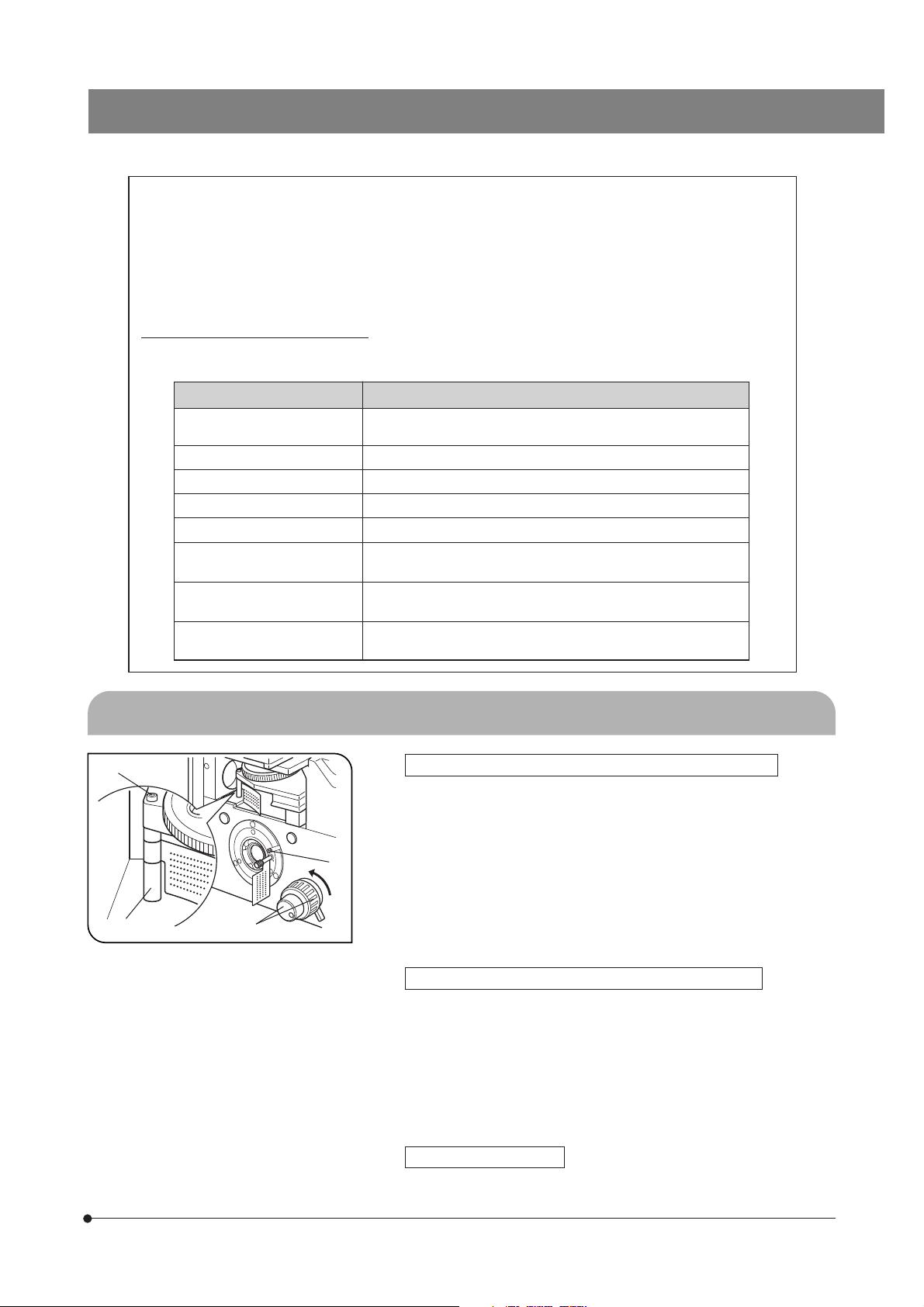
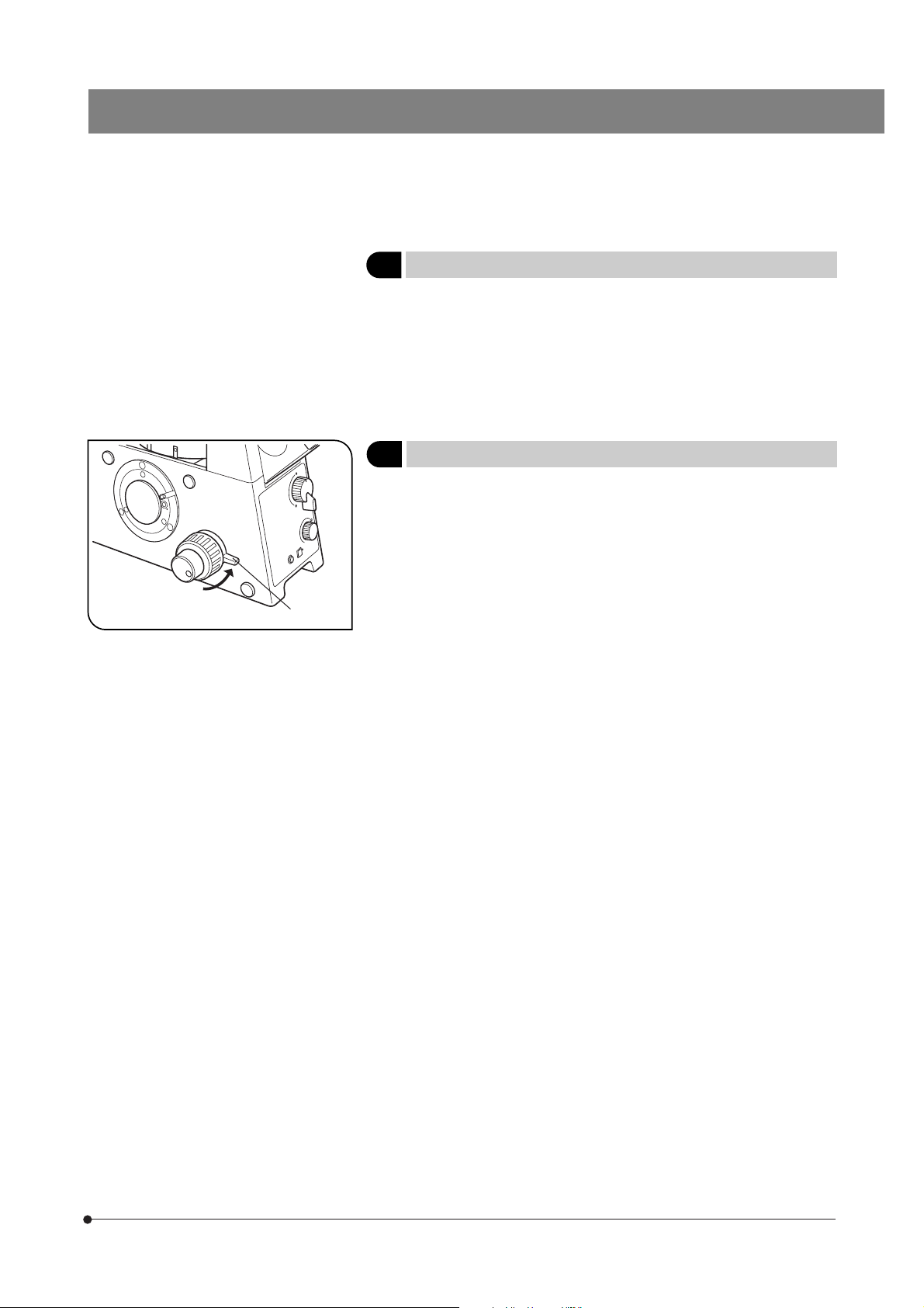
Releasing the Transport Lock of the Revolving Nosepiece
#Never attempt to rotate the coarse or fine adjustment knob @ without
removing the clamping rod. Otherwise, the focusing mechanism may
be damaged.
1. Loosen the screw ³ of the clamping rod ² using the Allen screwdriver
provided with the microscope frame.
2. Rotate the coarse and fine adjustment knobs @ in the direction of the
arrow and remove the clamping rod ².
Attach the provided seal (10 mm dia., black) on the hole made after remov-
3.
ing the transport lock knob to prevent penetration of dust through the hole.
}Retain the clamping rod ² and screw ³ carefully because they will be
used again the next time the microscope is transported.
Releasing the Transport Lock of the Light Path Selector
#Never attempt to operate the light path selector without removing the
transport lock knob |. Otherwise, the light path selector mechanism
may be damaged.
· Rotate the knob counterclockwise to remove it.
· To prevent penetration of dust through the hole made after removing the
transport lock knob, stop the hole by attaching the provided seal (10 mm
dia., black).
}Retain the knob carefully because it will be used again the next time the
microscope is transported.
Stage (IX2-SFR, IX-MVR)
· Before transporting the stage, fix the flexible knobs with pieces of
adhesive tape so that they will not move.
1
Page 6
@
IX2-ILL100
SAFETY PRECAUTIONS
²
Fig. 2
³
1. After the equipment has been used in an observation of a specimen that
is accompanied with a potential of infection, clean the parts coming in
contact with the specimen to prevent infection.
· Moving this product is accompanied with the risk of dropping the speci-
men. Be sure to remove the specimen before moving this product.
· In case the specimen is damaged by erroneous operation, promptly
take the infection prevention measures.
2. The microscope is provided with a simplified waterproof mechanism.
Therefore, if culture liquid or water is spilt on the stage, revolving nosepiece
or microscope frame, damage to the equipment or an electrical shock may
result. Immediately wipe the liquid or water off if it is spilt on them.
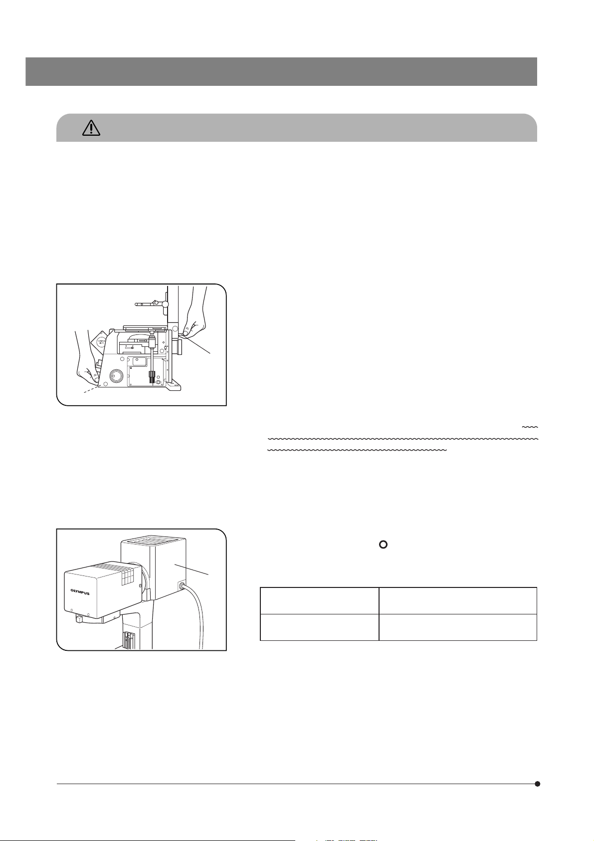
3. When moving the microscope, remove the observation tube, condenser
and reflected light mercury lamp housing, then carefully carry the microscope frame by the base (front edge) @ and the grasping part on the
illumination column ² as shown in Fig. 2. (Weight: approx. 20 kg)
Also be sure to remove the specimen since it may fall.
When moving the microscope for a long distance, it is also recommended
to disconnect all cables from the equipment.
When transporting it, also engage the transport lock mechanisms and
package it sufficiently.
Also be careful against slipping of hands during carrying.
#Damage to the microscope will occur if you grasp it by other parts
including the stage, coarse/fine adjustment knobs, etc.
4. The microscope is not covered by warranty in terms of laser safety. The
user should assume liabilities for any consequence of user modification
including introduction of the use of laser beam.
5. The surfaces of the lamp housing will become extremely hot during
operation. When installing the microscope, make sure to allow ample
free space (10 cm or more) around and in particular above the lamp
housing.
6. When installing the microscope, route the power cord away from the
lamp housing. Should the power cord come in contact with the hot lamp
housing, the power cord could melt and cause electric shock.
7. To avoid potential shock hazards and burns when replacing the light
bulb, set the main switch to “ ” (OFF) then disconnect the power cord
from the wall outlet in advance. Whenever you replace the bulb during
use or right after use, allow the lamp housing ³ and bulb to cool before
touching. (Fig. 3)
2
Fig. 3
Designated halogen bulb
(Illumination column: IX2-ILL100)
Designated halogen bulb
(Illumination column: IX2-ILL30)
8. Always use the power cord provided by Olympus. If no power cord is
provided, please select the proper power cord by referring to the section
“PROPER SELECTION OF THE POWER SUPPLY CORD” at the end of
this instruction manual. If the proper power cord is not used, product
safety performance cannot be warranted.
9. Always ensure that the grounding terminal of the microscope and that of
the wall outlet are properly connected. If the equipment is not grounded,
Olympus can no longer warrant the electrical safety performance of the
equipment.
10. Never insert metallic objects into the air vents of the microscope frame
as this could result in electrical shock, personal injury and equipment
damage.
12V100WHAL (PHILIPS 7724)
Bulb life: 2000 hours of rated operation
6V30WHAL (PHILIPS 5761)
Bulb life: 100 hours of rated operation
Page 7
IX71/IX51
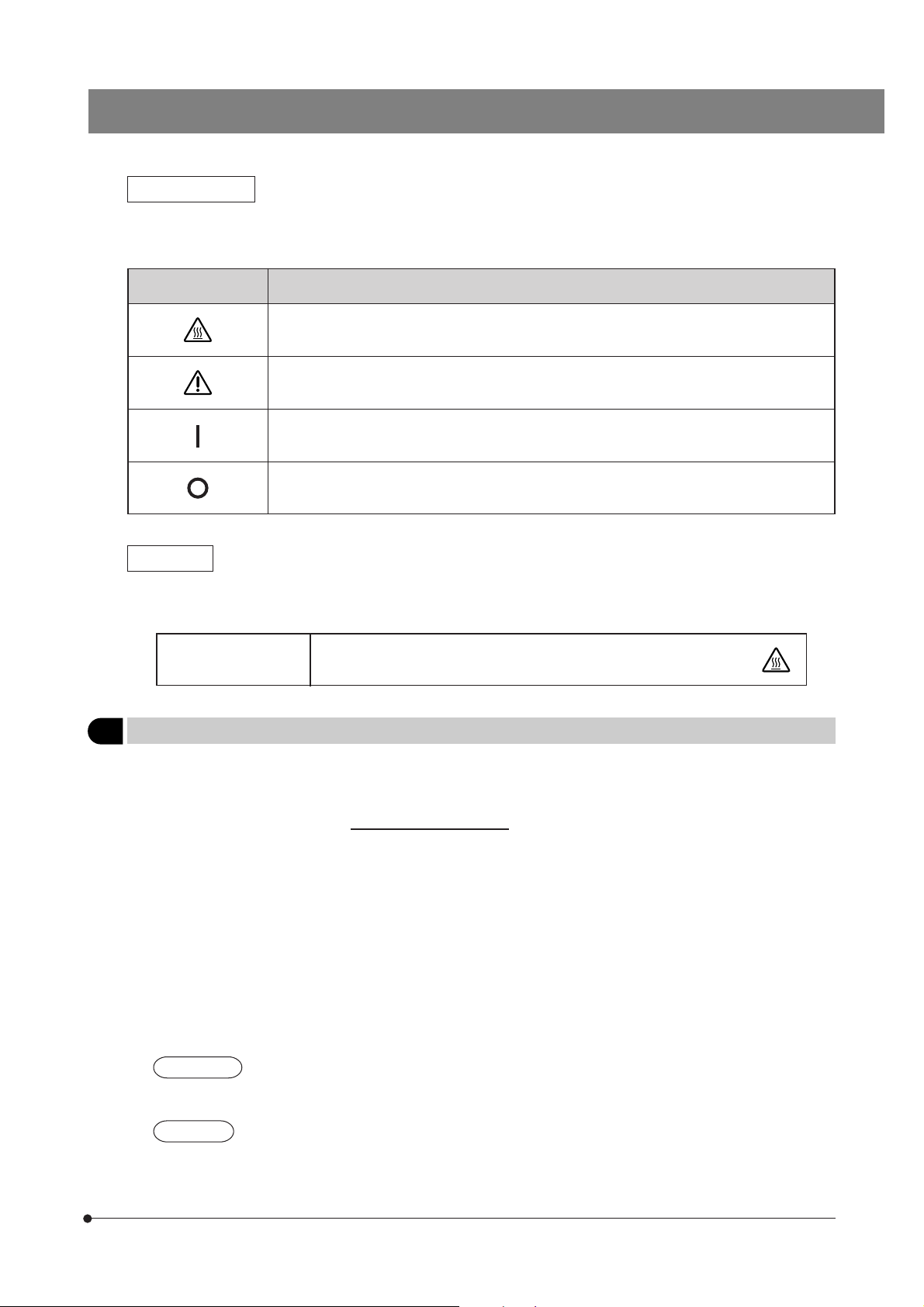
Safety Symbols
The following symbols are found on the microscope. Study the meaning of the symbols and always use the equipment
in the safest possible manner.
Symbol Explanation
Indicates that the surface becomes hot, and should not be touched with bare hands.
Before use, carefully read the instruction manual. Improper use could result in personal injury
to the user and/or damage to the equipment.
Indicates that the main switch is ON.
Indicates that the main switch is OFF.
Warnings
Warning engravings are placed at parts where special precaution is required when handling and using the microscope.
Always heed the warnings.
Warning engraving
position
Getting Ready
1
1. A microscope is a precision instrument. Handle it with care and avoid subjecting it to sudden or severe impact.
2. Do not use the microscope where it is subjected to direct sunlight, high temperature and humidity, dust or vibrations. (For
operating conditions, see Chapter 8, “SPECIFICATIONS” on page 54).
3. An intermediate attachment with a thickness of up to 60 mm can be mounted between the microscope frame and
binocular observation tube (U-BI90CT, U-BI90).
· If the U-TBI90 is used together with an intermediate attachment, the image may be cut off or obscured.
4. The oil-proof cap can only be mounted on a UIS Series 3 objective. Note that this does not change the optical
performance. (For applicable objectives, see page 30.)
5. Restrictions in brightfield, phase contrast and DIC observations
· When the U-BI90CT is used together with the optional 2X magnification changer built into the microscope frame, the
brightness in the peripheral area of the field may become insufficient.
(The insufficiency in brightness can be improved by extending the light path length using the U-EPA2 eye-point
adjuster.)
· With the combination of U-TR30H + U-FWO, the full optical performance may not be able to be manifested with the
objectives listed in @ below and it is not possible to use the objectives listed in ² below. (This also applies to
objectives other than Series 3 objectives.)
UIS2 Series
1UPlanSApo4X, 10X2, UPlanFLN4X, 10X2, 20X, CPlanFLN10X, LUCPlanFLN20X, UPlanSApo100XO
2PlanN40X, PlanApoN60XO
UIS Series
@UPlanApo4X, 10X, UPlanFl4X, 10X and 20X, CPlanFl10X, LCPlanFl20X, UPlanApo100XOI3
²Plan40X, UPlanApo40XOI3/340, PlanApo60XO3
Lamp housing
(U-LH100L-3, U-LH100-3, IX-HLSH100, U-LS30-3)
(High Temperature
warning)
3
Page 8

6. Restrictions in TV observation
@The following combinations are not permitted in consideration of the optical performance.
· IX2-SPT + PE4X + U-PMTVC on the side port
· IX2-SPT + PE5X + U-PMTV1X on the side port (With the IX71, this is applicable only when the magnification changer is
set to 1X.)
· U-TV0.35XC + 2X magnification changer (optional)
· U-TV0.35XC + DP50 (optional 2X magnification changer on the side port)
²The following combination may deteriorate the optical performance a little.
· U-TV0.35XC + DP50 (UPlanSApo/UPlanApo4X or 10X on the side port) (With the IX71, this is applicable only when the
magnification changer is set to 1X.)
7. Restrictions in fluorescence observation
· With combination of IX2-SHA + U-FWR (x 2) + U-LH100HGAPO, objectives UPlanSApo/UPlanApo40X, UPlanFLN/
UPlanFl20X, UPlanFLN100XO/100XOI, UPlanFl100XO3, PlanAPoN60XO and PlanApo60XO3 cannot be used due to a
problem in the optical performance. (This also applies to objectives other than Series 3 objectives.)
8. Other
· The U-TRU or U-TVCAC cannot be mounted on the side port.
· When a large module is attached to the U-TR30H straight photo tube, it will be difficult to confirm the specimen.
· Only either the lower back port or left side port can be used.
Maintenance and Storage
2
1. To clean the lenses and other glass components, simply blow dirty away using a commercially available blower and
wipe gently using a piece of cleaning paper (or clean gauze).
If a lens is stained with fingerprints or oil smudges, wipe it gauze slightly moistened with commercially available absolute
alcohol.
Since the absolute alcohol is highly flammable, it must be handled carefully.
Be sure to keep it away from open flames or potential sources of electrical sparks --- for example, electrical
equipment that is being switched on or off.
Also remember to always use it only in a well-ventilated room.
2. Be sure to clean the oil immersion objective after use. Leaving immersion oil on it will degrades its performance.
3. Do not attempt to use organic solvents to clean the non-optical components of microscope. To clean them, use a lint-free,
soft cloth slightly moistened with a diluted neutral detergent.
4. Never attempt to disassemble any part of the microscope.
5. When not using the microscope, make sure to set the main switch to “ ” (OFF), confirm that the lamp housing is cool
enough and cover the microscope with the provided dust cover.
4
Caution
3
If the microscope is used in a manner not specified by this manual, the safety of the user may be imperiled. In addition,
the equipment may also be damaged. Always use the equipment as outlined in this instruction manual.
The following symbols are used to set off text in this instruction manual.
: Indicates that failure to follow the instructions in the warning could result in bodily harm to the
user and/or damage to equipment (including objects in the vicinity of the equipment).
# : Indicates that failure to follow the instructions could result in damage to equipment.
} : Indicates commentary (for ease of operation and maintenance).
Intended use
4
This instrument has been designed to be used to observe magnified images of specimens in routine and research
applications.
Do not use this instrument for any purpose other than its intended use.
Page 9
IX71/IX51
MODULE NOMENCLATURE
}The modules shown below are only the representative modules. As there are other modules which can be combined
with the microscope but are not shown below, please also refer to the latest Olympus catalogues or your dealer.
For the modules marked *, refer to their separate instruction manuals.
Modules marked
}
are motorized modules, which should be used in combination with the IX2-UCB, a PC, etc.
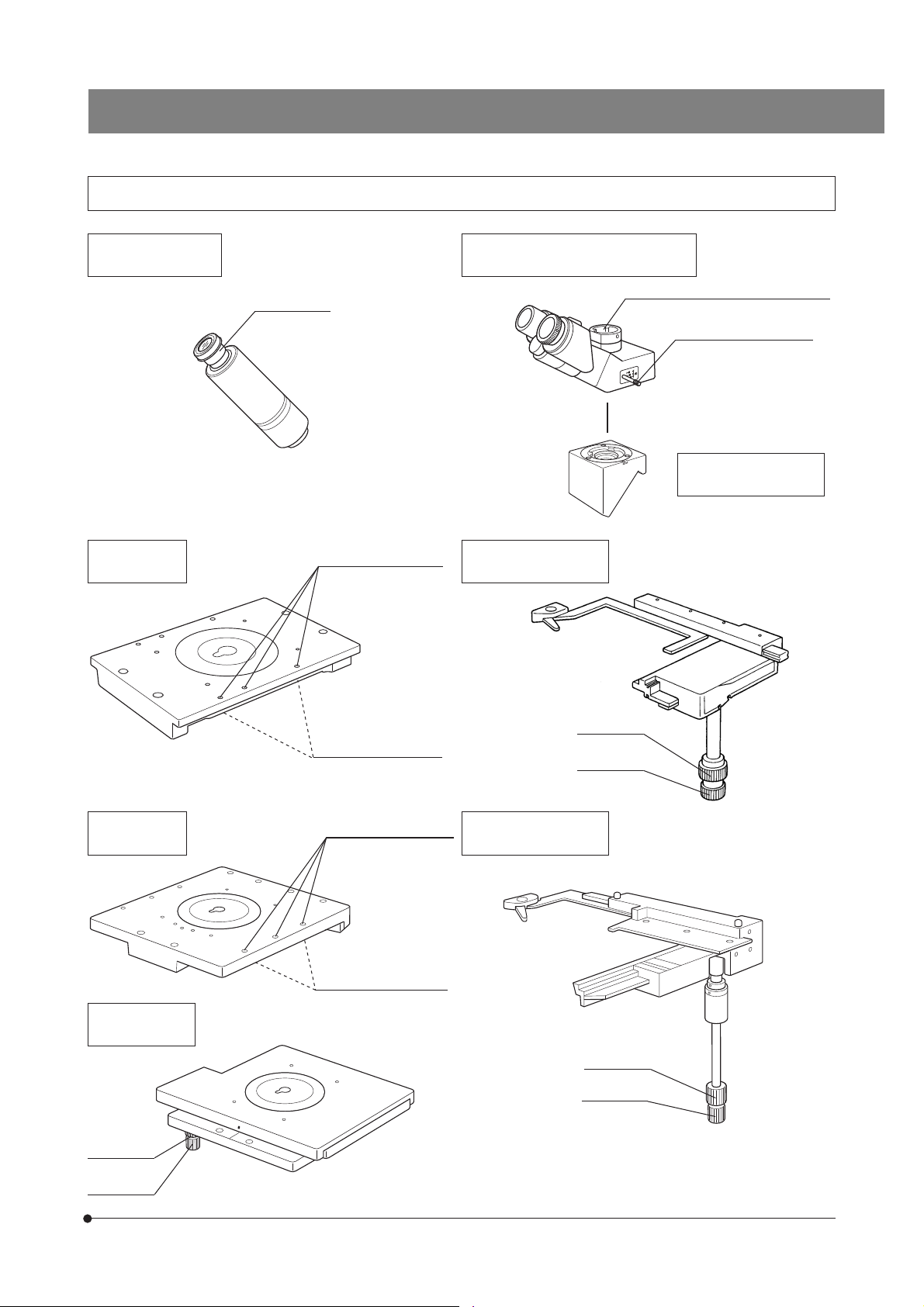
Condenser
· IX2-LWUCDA2
· IX2-LWUCD
· IX-ULWCD
· IX2-DICD*
· IX2-MLWCD*
· U-UCD8*
(Used together with IX-ADUCD)
Stage
· IX2-SFR
· IX-SVL2
· IX2-GS*
· IX2-SP
(Can be used together
with IX-MVR)
· IX2-KSP
(Can be used together
with CK40-MVR)
Eyepieces
· WHN10X
· WHN10X-H
}
Transmitted Light Lamp Housing
· U-LH100L-3
· U-LH100-3 + U-RMT
· IX-HLSH100 + U-RMT
Transmitted Light Illumination Column
· IX2-ILL100
· IX2-ILL30
Reflected Light Fluorescence Illuminator
· IX2-RFA*
· IX2-RFAL*
Reflected Light High-Intensity
Lamp Housing
· U-LH100HG*
· U-LH100HGAPO*
· U-LH75XEAPO*
High-Intensity Power
Supply Unit
· U-RFL-T*
· U-RX-T*
Observation Tube
· U-BI90CT
· U-BI90
· U-TBI90
· U-TR30H-2
(Used together with
IX-ATU)
· U-MO
6-Position Revolving
Nosepiece
(Fixed on the microscope
frame)
Microscope Frame
· IX71S1F-3
· IX71S8F-3
· IX51S1F-3
· IX51S8F-3
Fluorescence Mirror Unit
Cassette
· IX2-RFACA*
· IX2-RFAC*
}
Hand Switch
U-HSTR2*
Control Box
IX2-UCB*
Power Supply Unit
· TH4
· TL4
}
}
PC
(IX2-BSW Ver. 01.03 or later
software installed)
}
5
Page 10
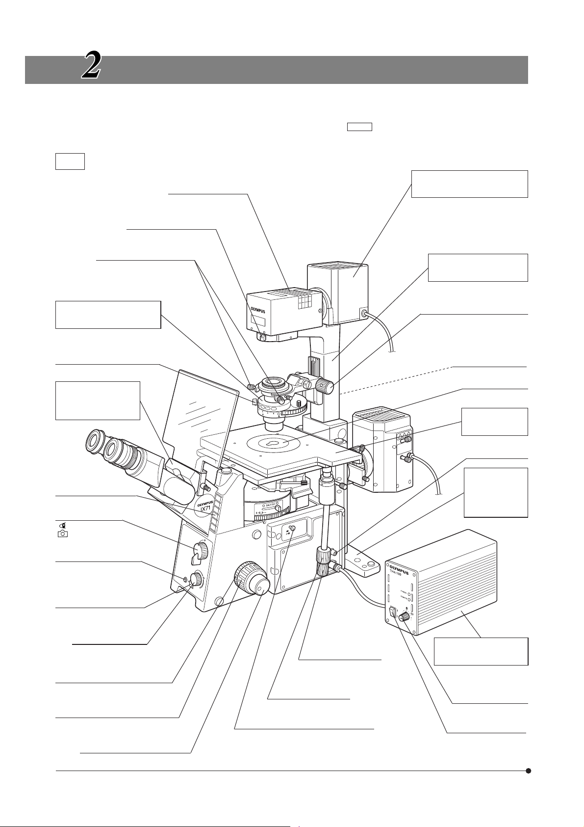
CONTROLS
}If you have not yet assembled the microscope, read Chapter 9, “ASSEMBLY” (pages 55 to 65).
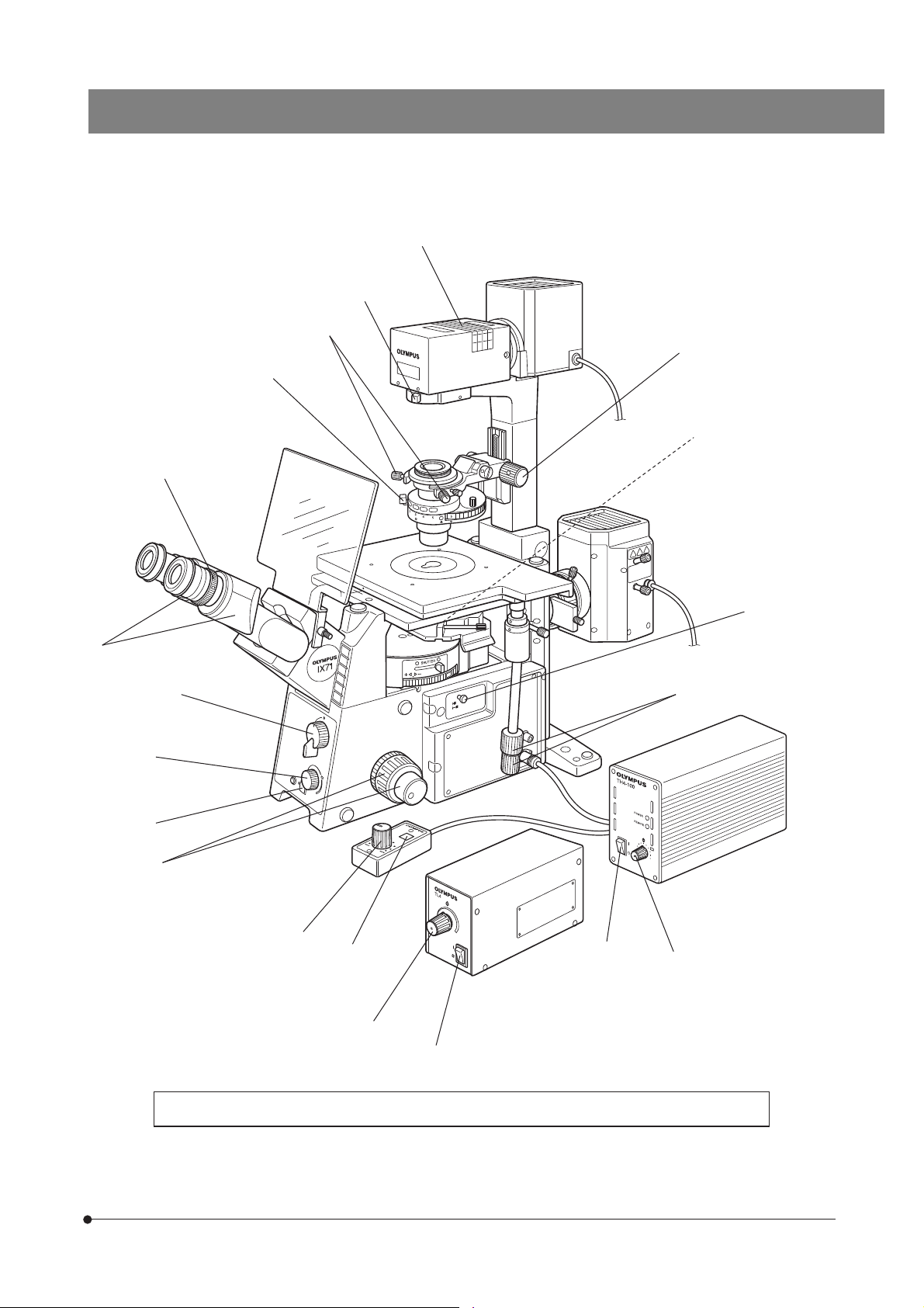
· The illustration shows the system composed of modules enclosed in .
IX71
Field iris diaphragm lever
Condenser centering knobs
Universal Condenser
IX2-LWUCD
Aperture iris diaphragm lever
Tilting Binocular
Tube
U-TBI90
Filter pocket (Page 23)
Halogen Lamp Housing
U-LH100L-3
Applicable halogen bulb:
12V100WHAL-L
Illumination Column
IX2-ILL100
Condenser height adjustment
knob (Page 27)
Column tilt clamping
screw (Page 22)
Stage center plate
Cross Stage
IX2-SFR
Option connector
(Page 16)
Indicator plate pockets
Light path selector
lever (Page 15)
: Observation/
: Side port
Option button (Page 16)
Transmitted light ON-OFF
button (Page 14)
Light intensity control
knob (Page 14)
Coarse adjustment knob tension
adjustment ring (Page 16)
Coarse adjustment knob (Page 16)
Fine adjustment knob (Page 17)
Detachable.
X-axis knob (Page 19)
Y-axis knob (Page 19)
Magnification selector knob (Page 15)
Pushed in: 1X
Pulled out: 1.6X
Microscope
Frame
IX71S1F-3
IX71S8F-3
Power Supply Unit
TH4
Light intensity control
knob (Page 14)
Main switch (Page 14)
6
Page 11
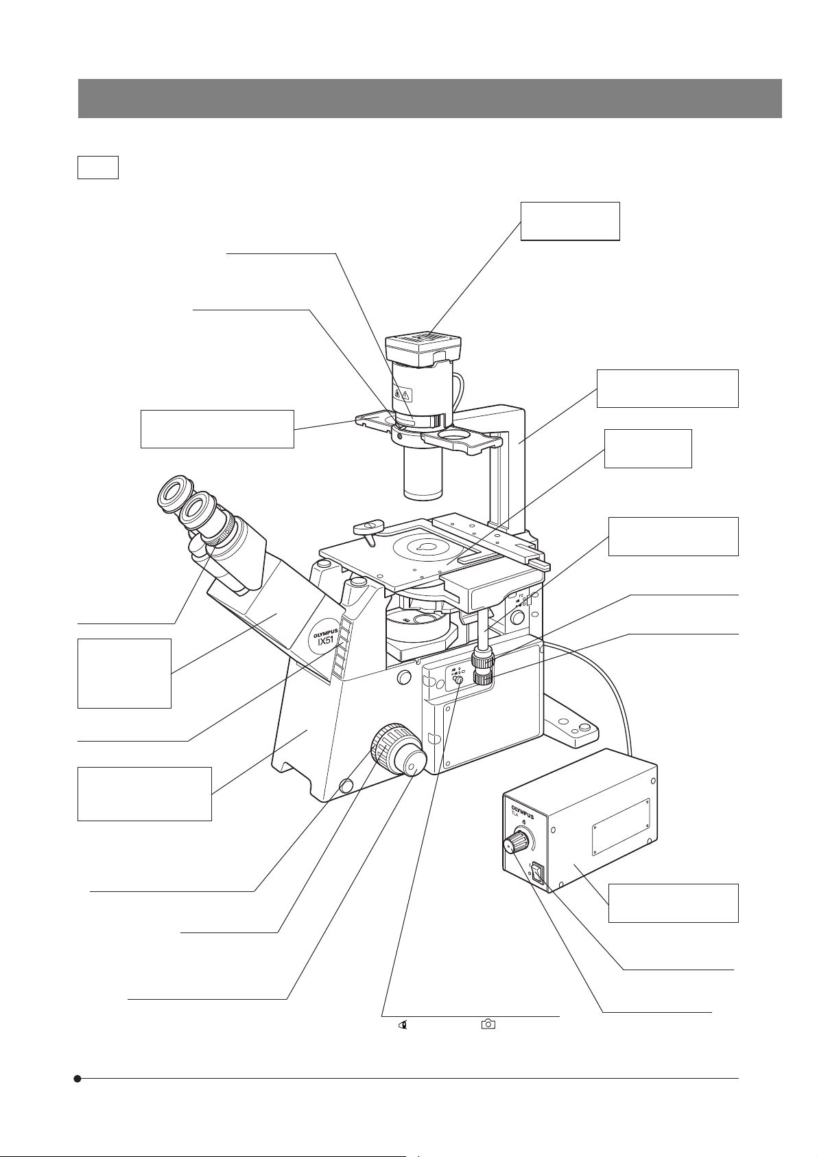
IX51
Filter holder (Page 26)
Aperture iris diaphragm
lever (Page 25)
Phase Contrast Slider
IX2-SL
IX71/IX51
Lamp Socket
U-LS30-3
Applicable halogen bulb:
6V30WHAL
Illumination Column
IX2-ILL30
Plain Stage
IX2-KSP
Diopter adjustment
ring (Page 20)
Binocular
Observation
Tube
U-BI90
Indicator plate pocket
Microscope Frame
IX51S1F-3
IX51S8F-3
Coarse adjustment knob tension
adjustment ring (Page 16)
Coarse adjustment
knob (Page 16)
Mechanical Stage
CK40-MVR
Y-axis knob (Page 19)
X-axis knob (Page 19)
Power Supply Unit
TL4
Fine adjustment knob (Page 17)
Detachable.
Light path selector lever (Page 15)
: Observation/ : Side port
Main switch (Page 14)
Light intensity control
knob (Page 14)
7
Page 12
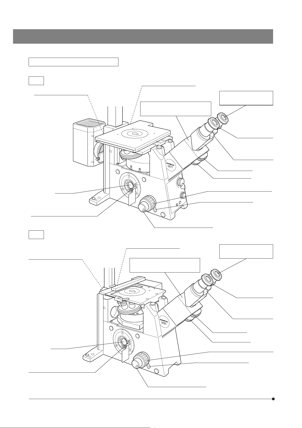
Left Side View of Microscope Frame
IX71
Allen screwdriver
storage position (Rear panel)
Side port
Transport lock knob
#Be sure to remove this before use.
IX51
Allen screwdriver
storage position (Rear panel)
Allen wrench and optical
element centering knob (x 2)
storage position (Rear panel)
Binocular Observation Tube
U-BI90CT
Fine adjustment knob (Page 17)
Allen wrench and optical
element centering knob (x 2)
storage position (Rear panel)
Binocular Observation Tube
U-BI90CT
Eyepieces
WHN10X/WHN10X-H
CT turret (Page 21)
Focus ring (Page 21)
Coarse adjustment knob (Page 16)
Pre-focusing lever (Page 17)
Detachable.
Eyepieces
WHN10X/WHN10X-H
Diopter adjustment
ring (Page 20)
Interpupillary distance
adjustment scale
(Page 20)
Side port
Transport lock knob
#Be sure to remove this before use.
8
Pre-focusing lever (Page 17)
Fine adjustment knob (Page 17)
Detachable.
Diopter adjustment
ring (Page 20)
Interpupillary distance
adjustment scale
(Page 20)
CT turret (Page 21)
Focus ring (Page 21)
Coarse adjustment knob (Page 16)
Page 13
Other Modules
IX71/IX51
Monocular Tube
U-MO
Plain Stage
IX2-KSP
10X eyepiece
(Fixed)
Manipulator mounting
screw holes
M6 screws (x 6)
Trinocular Observation Tube H
U-TR30H-2
Straight photo tube mount (Page 44)
Mechanical Stage
CK40-MVR
}Can be mounted on the IX2-KSP.
Light path selector knob
(Page 21)
Intermediate Tube
IX-ATU
Plain Stage
IX2-SP
Cross Stage
IX-SVL2
Y-axis knob
CK40-MVR/CK2-SS
mounting screw holes
(On both sides)
Manipulator mounting
screw holes
M6 screws (x 6)
IX-MVR/CK2-SS
mounting screw holes
(On both sides)
Y-axis knob
X-axis knob
Mechanical Stage
IX-MVR
Y-axis knob
X-axis knob
}Can be mounted on the IX2-SP.
X-axis knob
9
Page 14
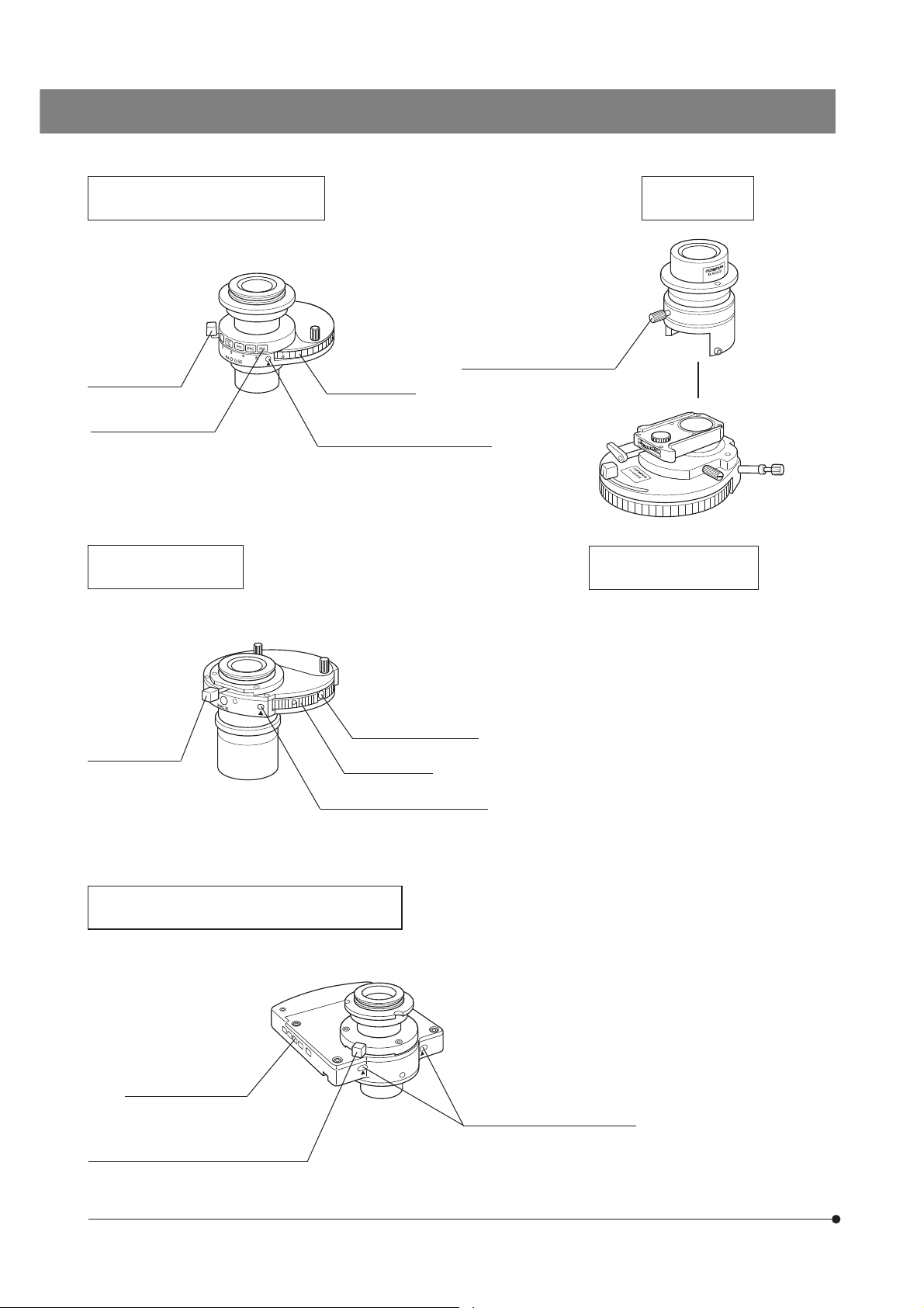
Long WD Universal Condenser
IX2-LWUCD
}This is a manually controlled condenser.
UCD Adapter
IX-ADUCD
Aperture iris
diaphragm lever
(Page 27)
Index mounting holes
Centering knob insertion holes
ULWCD Condenser
IX-ULWCD
}This is a manually controlled condenser.
Aperture iris
diaphragm lever
(Page 27)
Turret (Page 27)
Index mounting holes
Turret (Page 27)
Condenser height fine
adjustment knob (Page 28)
(x 2)
(x 2)
Universal Condenser
U-UCD8
}This is a manually controlled condenser.
Refer to the separate instruction manual
for details.
10
Centering knob insertion hole
Motorized Long WD Universal Condenser
IX2-LWUCDA2
}This is a motorized condenser.
Index mounting holes
Centering knob insertion holes
Aperture iris diaphragm lever (Page 27)
Page 15
IX71/IX51
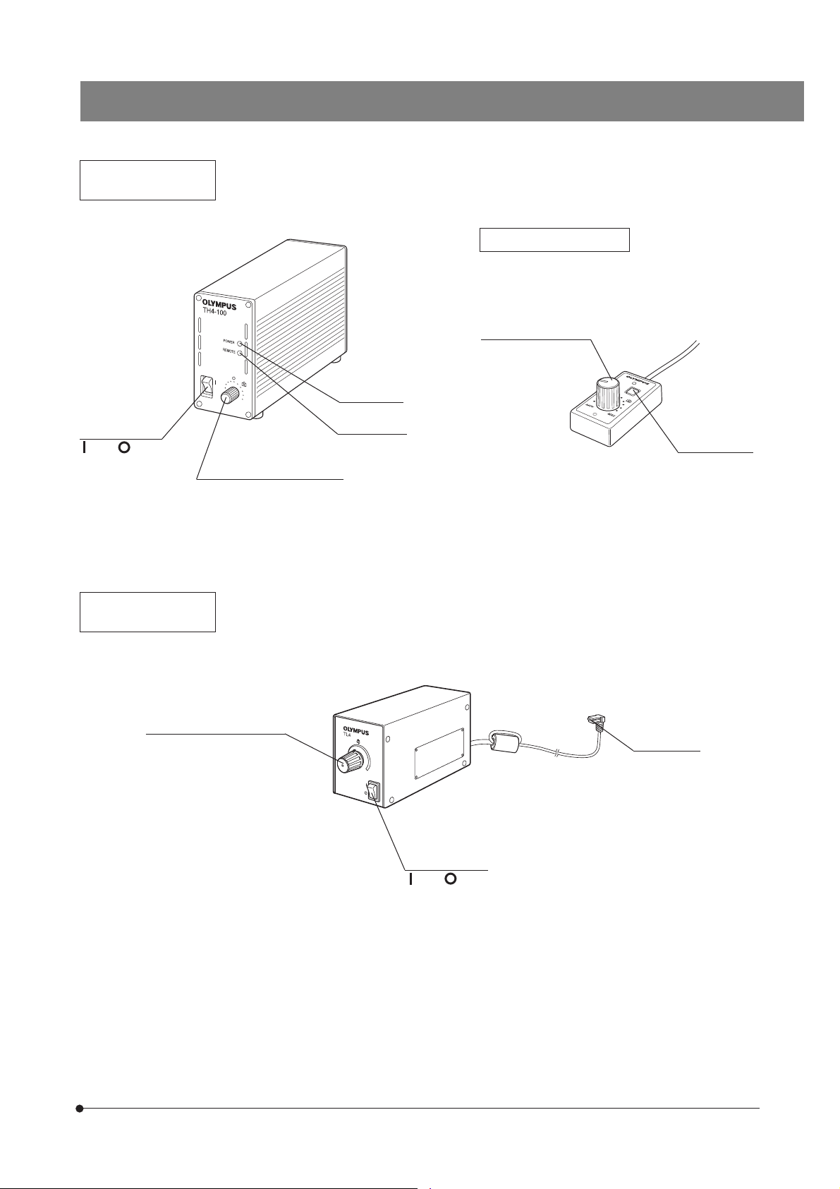
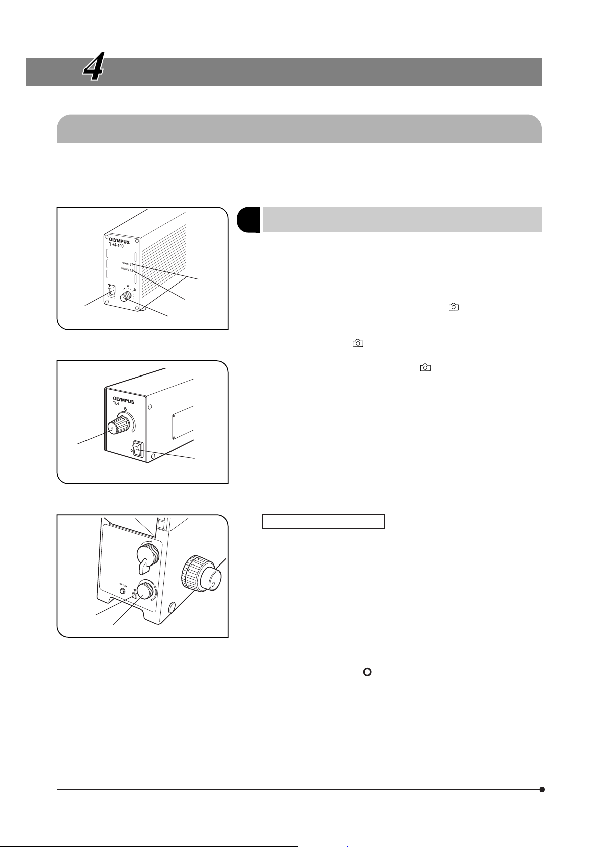
Power Supply Unit
TH4
Main switch
: ON. : OFF.
}The applicable halogen bulb is the 12V100WHAL-L.
For details, refer to the separate instruction manual.
POWER LED
REMOTE LED
Light intensity control knob
Hand Switch TH4-HS
}The IX71 does not need this module because its
functions are incorporated in the microscope frame.
Light intensity control
knob
Lamp ON-OFF
switch
Power Supply Unit
TL4
Light intensity control knob
}The applicable halogen bulb is the 6V30WHAL .
Main switch
: ON. : OFF.
Lamp socket
connector
11
Page 16
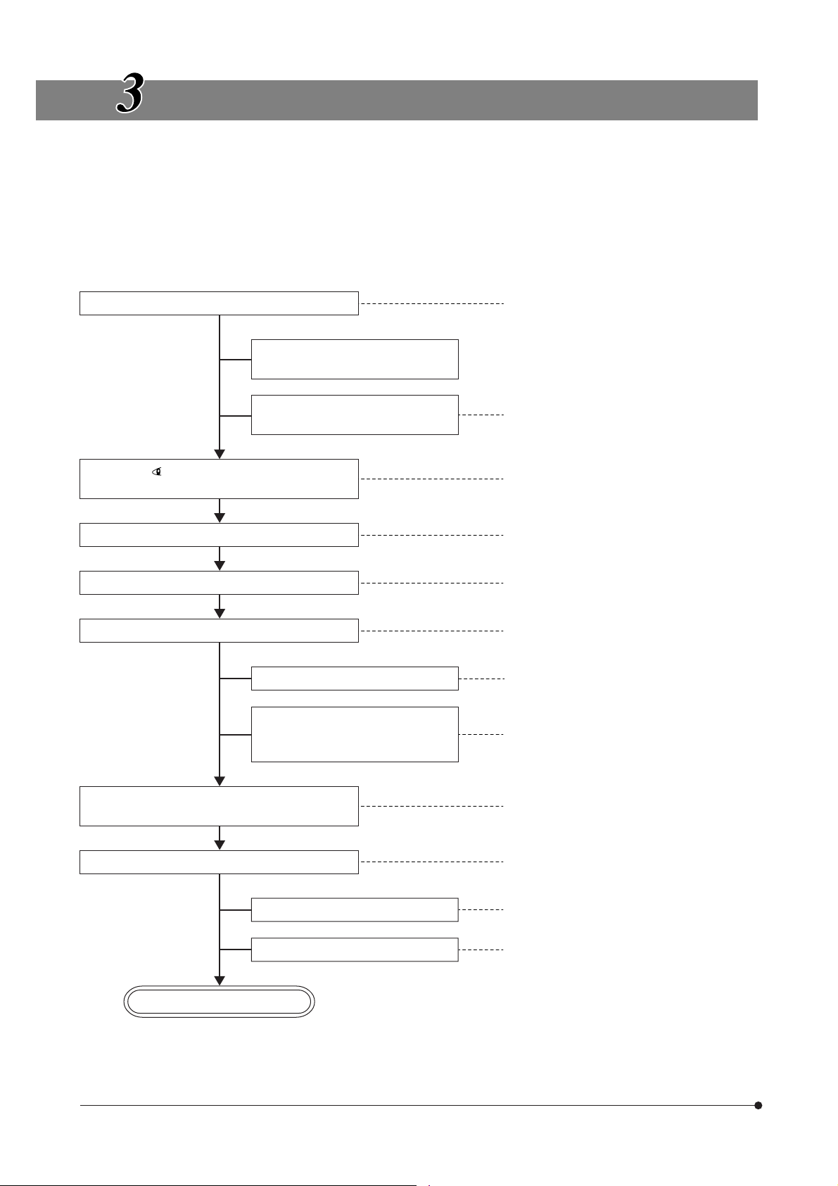
TRANSMITTED LIGHT BRIGHTFIELD
OBSERVATION PROCEDURE
}The following flow shows the operating procedure for the transmitted light brightfield observation which is the basic
observation method of this microscope. The operating procedures for phase contrast observation and DIC observation
will be described separately in Chapter 5, “OTHER OBSERVATION METHODS” on page 32.
For the fluorescence observation, refer to the separate instruction manual entitled “Manual/Motorized Reflected Fluorescence System”.
(Controls Used) (Page)
@Main switch: “ I ” (ON) (P. 14)
Set the main switch to “ I ” (ON).
Disengage the DIC slider and
analyzer from the light path.
²Lamp ON-OFF button: ON (P. 14)
³Light intensity control knob (P. 14)
Disengage the filter other than the
frost filter from the light path.
Select the (observation) light path with the
light path selector lever.
Place the specimen on the stage.
Engage a 10X objective in the light path.
Bring the specimen into focus.
Adjust the brightness.
Adjust the interpupillary distance.
Adjust the diopter.
Adjust the light axis.
Engage the objective to be used in the light
path and bring the specimen in focus.
|Filter pocket (P. 23/26)
ƒLight path selector lever (P. 15)
…X-axis and Y-axis knobs (P. 19)
†Revolving nosepiece
‡Coarse/fine adjustment knobs (P. 16)
³Light intensity control knob (P. 14)
ŠBinocular observation tube (P. 20)
‰Diopter adjustment ring (P. 20)
‹Condenser height adjustment knob* (P. 27/
28)
ŒCondenser centering knobs* (P. 27/28)
™Field iris diaphragm lever* (P. 24)
†Revolving nosepiece
‡Coarse/fine adjustment knobs (P. 16)
12
Adjust the aperture iris and field iris diaphragms.
Engage the required filters.
Adjust the brightness.
Start observation.
* This operation is not required when the IX2-ILL30 illumination column is used.
šAperture iris diaphragm lever (P. 29)
™Field iris diaphragm lever* (P. 24)
|Filter pocket (P. 23/26)
³Light intensity control knob (P. 14)
Page 17
‰
IX71/IX51
|
™
Œ
‹
š
†
Š
ƒ
With the IX71
³
²
‡
Hand Switch
TH4-HS
³
²
³
When the TL4 power
supply unit is used
@
@
ƒ
With the IX51
…
Power Supply Unit
TH4
³
} Make a photocopy of the observation procedure pages and post it near your microscope.
13
Page 18
USING THE CONTROLS
4-1 Power Supply Unit and Microscope Frame
}The power supply unit to be used is variable depending on the illumination column in use.
· IX2-ILL100: TH4 power supply unit.
· IX2-ILL30: TL4 power supply unit.
@
²
Fig. 4
Fig. 5
@
|
²
³
Turning Power On, Adjusting the
1
Brightness
1. Make sure that the light intensity control knob @ is in the MIN (minimum
intensity) position and set the main switch ² to “ I ” (ON). (The POWER
LED ³ lights up.)
2. Rotate the knob @ toward MAX (maximum intensity) to increase the
intensity and the illumination brightness.
}With the TH4, the position (approx. 9 V) marked indicates the position
where the daylight illumination suitable for photomicrography is obtained
when the 45LBD filter is engaged in the light path.
The position marked of the IX71 and TH4-HS also has the identical
function.
With the TL4, the position marked is not provided and even
the maximum light intensity (6 V) may sometimes be unsuitable
for photomicrography.
(Figs. 4 & 5)
14
…
ƒ
Fig. 6
With the IX71 Frame (Fig. 6)
}If the TH4 connection cable provided with the microscope frame is
connected to the TH4 (the REMOTE LED | lights in this case), the light
intensity control knob @ on the power supply unit is defeated and only
the light intensity control knob ƒ on the front of the microscope frame
is available.
1. Press the transmitted light ON-OFF button … (so that the button is illuminated) and adjust the brightness with the light intensity control knob ƒ.
2. To turn the lamp OFF, set the transmitted light ON-OFF button … to OFF.
#The microscope frame is in standby mode when the REMOTE LED
| is lit. Power of about 2.5 W is consumed in this period.
When the microscope system is not be used for a long period, set
the main switch ² to “ ” (OFF).
Page 19
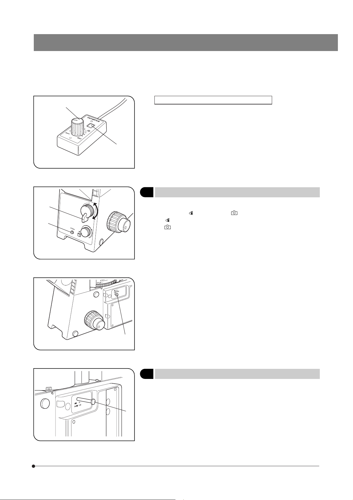
ƒ
IX71/IX51
When the TH4-HS Hand Switch is Used (Fig. 7)
}The illumination brightness can be adjusted from the hand switch in the
same way as on the IX71 microscope frame.
The hand switch is provided with double-sided adhesive tape, so it can
be adhered to an easy-to-use position.
…
Fig. 7
IX71
IX51
²
@
Fig. 8
Fig. 9
@
Light Path Selection
2
}The light path selector lever allows for light path switching between the
observation ( ) and side port ( ) paths.
: Observation 100% light path.
: Side port 100% light path (with the IX71S1F-2/IX51S1F-2 frame)
Side port light path 80%/Observation 20% light path (with the
IX71S8F-2/IX51S8F-2)
}The light path to the lower back port can also be set by the manufacturer’s
part replacement operation. (IX2-LBPC)
(Figs. 8 & 9)
IX71
Fig. 10
@
Magnification Change (IX71 Only)
3
When the magnification selector knob @ is pulled out, the magnification
will be 1.6X. When the knob is pushed in, the magnification will be 1X.
}The 1X 1.6X magnification changer lens can be replaced with a 1X 2X
magnification changer lens (IX2-CA2) by the manufacturer operation.
(Fig. 10)
15
Page 20
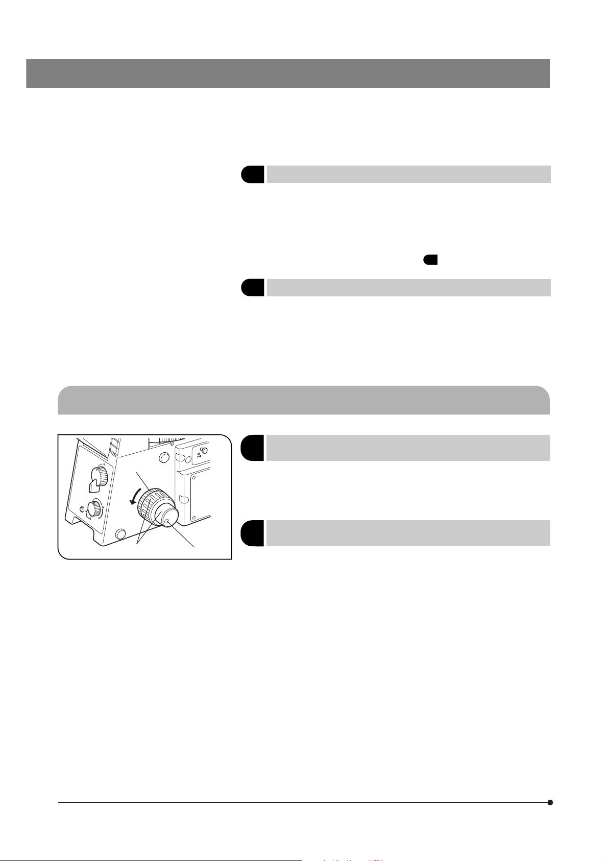
Frame Clamping Plate
4
}This is the module for clamping the microscope frame onto an
anti-vibration platform. The applicable anti-vibration platforms are
the following four models
· 25 mm pitch and 50 mm pitch anti-vibration platforms.
· 1-inch pitch and 2-inch pitch anti-vibration platforms.
For the assembly procedure, see item 10 on page 65.
4-2 Focusing Block
²
@
Fig. 11
³
Option Button (IX71 Only)
5
}
Pressing the option button ² makes it possible to release or close an
external shutter (UNIBLITZ, etc.) To do this, the external shutter be connected to the right side of the frame using a commercially available
BNC cable.
#When the option button is not used, leave the cap attached to it.
Rotation Direction of the Coarse/
1
Fine Adjustment Knobs
}Rotating the coarse or fine focus adjustment knob @ toward the front
(in the direction of the arrow) raises the objective and toward the rear
(opposite direction) lowers the objective.
Adjusting the Coarse Adjustment Knob
2
Tension
#Always use the rotation tension adjustment ring ² to control the
rotation tension of the coarse adjustment knob.
The tension of the coarse adjustment knob has been pre-adjusted to
optimum tension, but this can be changed as required. Turn the rotation
tension adjustment ring ² in the direction of the arrow to decrease the
knob’s tension and in the opposite direction to increase it.
If the objective lowers by its own weight or the focusing obtained with the
fine adjustment knob is lost soon, the tension is set too low. In this case,
turn the rotation tension adjustment ring in the opposite direction to the
arrow to increase the tension.
(Fig. 8)
(Fig. 11)
(Fig. 11)
16
Page 21
IX71/IX51
Fig. 12
@
Detaching the Fine Adjustment Knob
3
}The fine adjustment knob is designed detachable in order to prevent
interference between the knob and the operator’s hand manipulating the
X- and Y-axis knobs.
· Loosen the clamping screw ³ using the Allen screwdriver and remove
the fine adjustment knob.
After detaching, the seat of the fine adjustment knob is hollowed to
facilitate manipulation with the thick of a finger.
Pre-focusing Lever
4
}The pre-focusing lever prevents collision between the specimen and
objective and simplifies the focusing operation.
After bringing the specimen into approximate focus with the coarse
adjustment knob, turn the pre-focusing lever @ in the direction of the
arrow to lock it. Hereafter, the upper limit of the coarse adjustment will
be limited at the position where the lever is locked.
When bringing a specimen in focus, approximate focus can be obtained
by simply raising the coarse adjustment to the stop position so all you
have to do more is control the fine adjustment knob.
}The stage up/down movement using the fine adjustment knob is not
limited.
#When the pre-focusing lever is locked, the coarse adjustment stroke is
limited by the mechanism and it cannot reach the previous lower limit.
If you want to control the coarse adjustment knob to the previous lower
limit, unlock the pre-focusing lever.
(Fig. 11)
(Fig. 12)
17
Page 22
4-3 Stage
@
Fig. 13
Fig. 14
@
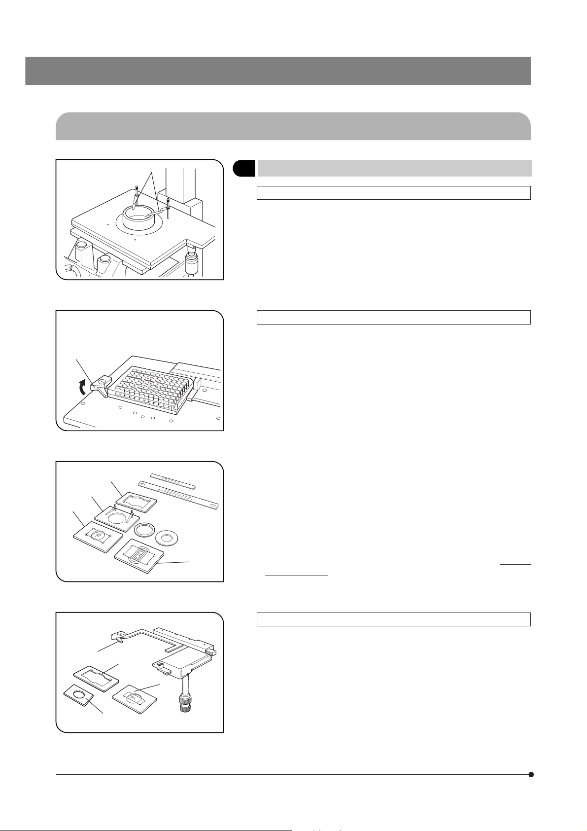
1 Placing the Specimen
With the IX2-SFR or IX-SVL2 Stage (Fig. 13)
Place the specimen on the center of the stage.
}In the case of a slide glass specimen, place the specimen with the cover
glass facing down.
}If the specimen is prone to slide on the stage, attach the stage clips
(IX-SCL) @ and clamp the specimen down with the clips.
With the IX-MVR Mechanical Stage + IX2-SP Stage (Figs. 14 & 15)
}96-well or 24-well microtiter plates, etc. are held in place by the speci-
men holder.
Microtiter plates with dimensions of max. 136 mm x 92 mm can be
accommodated in this way.
1. Open the spring-loaded finger of the specimen holder @ and slide the
microtiter plate into the holder frame. Gently release the curved finger to
clamp. (Fig. 14)
(Figs. 13 to 16)
|
³
@
|
²
²
Fig. 15
Fig. 16
³
ƒ
}To secure other vessels than microtiter plates, various optional holders
are available. A Terasaki plate holder ² is available for holding Terasaki
plates (72-well, or 60-well). When using this, it is necessary to replace the
stage scales with those provided with the plate holder. Petri dish holder
³ is available for 35 mm, 54 mm and 65 mm diameter petri dishes, and
a slide glass holder | is available for holding slide glass, and the IX2BCTP* ƒ is available for a blood cell test plate holder. (Fig. 15)
* A blood cell test plate or other calculating chamber for bacteria and
eosinophil with mounting section dimensions corresponding to H 77 x
+0.3
+0
V 35 x D 2 mm can be used. A 60 mm diameter petri dish can also be
used.
With the CK40-MVR Mechanical Stage + IX2-KSP Stage (Fig. 16)
1. 96-well or 24-well microtiter plates can be held directly in place by
widening the specimen holder @.
2. To secure other vessels than microtiter plates, use one of the following
holders provided with the mechanical stage.
· Terasaki plate holder ² (AB4488): For test plate, 35 mm diameter petri
dish holder | or 65 mm diameter petri dish
· Slide glass holder ³ (AB4489): For slide glass or 54 mm petri dish
}The IX2-BCTP blood cell test plate holder (Fig. 15 ƒ) can also be used.
+0.3
+0
18
Page 23
IX71/IX51
³
Fig. 17
²
²
@
Moving the Specimen
2
With the IX2-SFR or IX-SVL2 Stage
To move the specimen to a desired position, rotate the X-axis knob @
and Y-axis knob ².
}When the index mark on the upper stage is aligned with the index line ³
provided on the substages, the center of the stage center plate aperture
is almost in the center of the optical axis. Use this as a guideline when
moving the specimen.
The travel area is 50 mm (X-axis) x 50 mm (Y-axis).
}If, after observing a specimen with an objective with short WD (0.5 mm
or less), the revolving nosepiece is rotated to change the objective, the
objective may interfere with the center plate. When using objectives
with short WD or immersion objectives frequently by avoiding interference,
it is recommended to attach the optional IX-CP50 center plate with a
center aperture diameter of 50 mm.
}The travel area of the IX-SVL2 stage is 50 mm (X-axis) x 43 mm (Y-axis).
With the IX-MVR or CK40-MVR Mechanical Stage
Specimens are moved in the same manner as outlined above.
}The stage travel area is 130 mm (X-axis) x 85 mm (Y-axis) with the IX-MVR
or 120 mm (X-axis) x 78 mm (Y-axis) with the CK40-MVR.
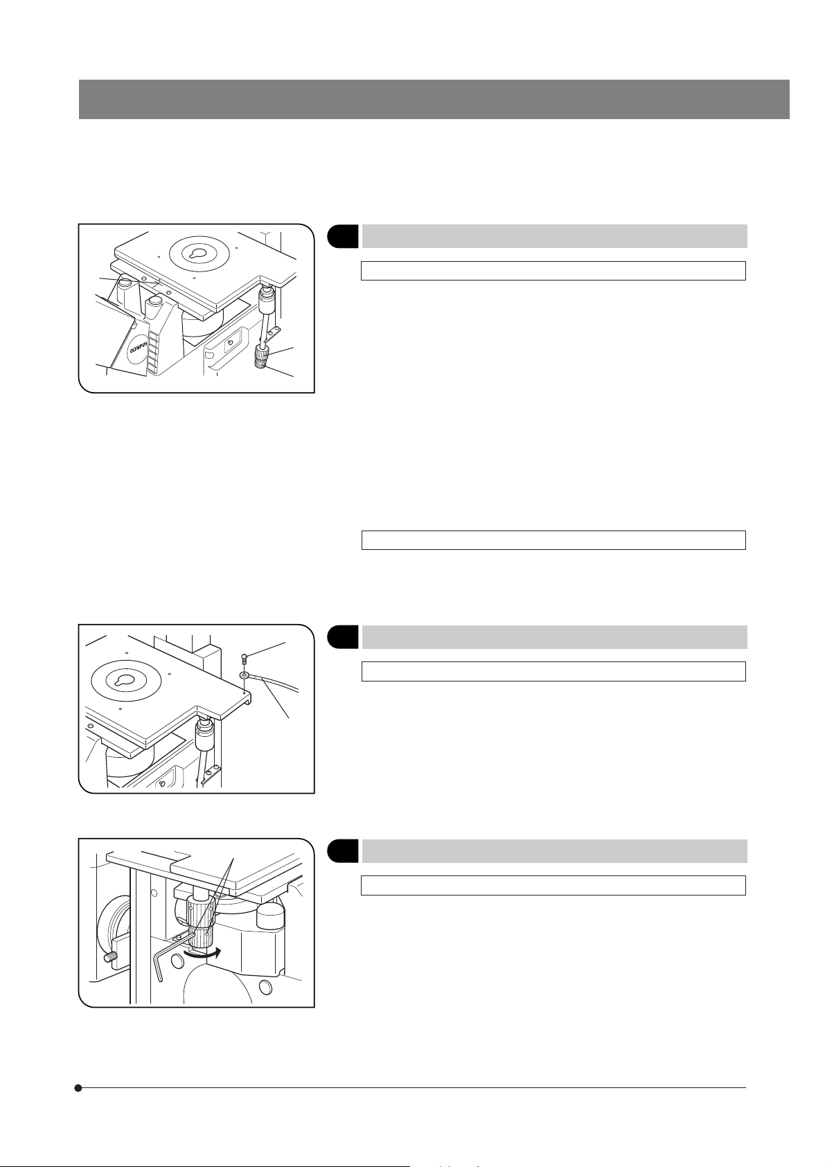
Connecting the Grounding Wire
3
(Fig. 17)
(Fig. 18)
Fig. 18
Fig. 19
@
@
With the IX2-SFR or IX-SVL2 Stage
}A grounding wire can be attached to the stage for electrophysiological
experiments, etc.
Prepare a grounding wire @ and one M4 screw ² and attach the
grounding wire as shown in Fig. 18.
#The screw hole may sometimes be stuck by paint, etc. In such a
case, screw in the M4 screw a few times to expose the metallic
thread inside the screw hole and improve the contact before
attaching the grounding wire firmly.
Adjusting the X-Axis/Y-Axis Knob Rotation Tension
4
With the IX-SVL2 Stage
}The tension of the X-axis and Y-axis knobs can be adjusted independently.
1. Loosen the two setscrews @ of a knob using the provided Allen wrench,
hold the stage so that it will not move, then rotate the knob to adjust the
tension. Rotating it in the direction of the arrow increases the tension and
rotating in the opposite direction decreases the tension.
2. After adjustment, tighten the setscrews firmly.
#If the tension of a knob is too tight or too loose, skipping or returning
of image may occur during the stage movement.
(Fig. 19)
19
Page 24

4-4 Observation Tube
²
Fig. 20
Fig. 21
@
Adjusting the Interpupillary Distance
1
While looking through the eyepieces, adjust the binocular vision until the
left and right fields of view coincide completely. The index dot · indicates
the interpupillary distance.
}Note your interpupillary distance so that it can be quickly duplicated.
Adjusting the Diopter
2
}The diopter adjustment accuracy can be improved by using an objective
with as high power as possible.
1. While looking through the right eyepiece, rotate the diopter adjustment
ring @ on the right eyepiece sleeve until the peripheral area of the field of
view is clearly visible. (Fig. 21)
}The diopter can also be adjusted using the eyepiece micrometer disks.
2. While looking through the right eyepiece, rotate the coarse/fine adjustment
knobs to bring the specimen into focus.
3. Look through the left eyepiece and rotate only the diopter adjustment
ring ² on the left eyepiece to bring the specimen into focus. (Fig. 21)
#When rotating the diopter adjustment ring of an eyepiece, hold the
lower part of the eyepiece with the other hand.
(Fig. 20)
(Figs. 21 & 22)
Fig. 22
Fig. 23
Operation When Using Finder Eyepieces (U-TR30H-2 Trinocular Tube Only)
}Note that the finder eyepieces cannot be attached to the eyepiece sleeves
of a binocular observation tube.
1. Looking through the left eyepiece with your left eye, rotate the top of the
eyepiece ² until a clearly defined double crosslines can be seen in the
field of view. (Figs. 21 & 22)
2. Looking through the left eyepiece, adjust the coarse/fine adjustment knobs
to bring the specimen and double crosslines into simultaneous focus.
3. Looking through the right eyepiece with your right eye, rotate only the
diopter adjustment ring @ to bring the specimen into focus.
Using the Eye Shades
3
When Wearing Eyeglasses
Use with the eye shades in the normal, folded-down position. This will
prevent the eyeglasses from being scratched.
When Not Wearing Eyeglasses
Extend the folded eye shades in the direction of the arrow to prevent
extraneous light from entering between the eyepieces and eyes.
(Fig. 23)
20
Page 25

IX71/IX51
Fig. 24
@
Fig. 25
@
²
Using Eyepiece Micrometer Disks
4
Eyepiece micrometer disks can be inserted into the WHN10X-H (or
WHN10X) eyepieces.
Use 24 mm dia. x 1.5 mm micrometer disks.
Following Fig. 24, turn the built-in micrometer mounting frame ² counterclockwise to remove it from the eyepiece and place a micrometer disk @
into the mounting frame so that the surface with the model indication
faces downward.
Re-attach the micrometer mounting frame in the original position.
Selecting the Light Path of Observation
5
Tube (U-TR30H-2 Only)
Slide the light path selector knob @ to select the desired light path.
}Usually, set the selector knob to the middle position. With dark speci-
mens, push the knob in. If additional light is needed for TV observation or
photomicrography, pull the knob out.
Light Path
Selector Position
Pushed in Binocular 100% Observation of dark
Middle Binocular 20%
Pulled out TV/photo 100% Photomicrography,
Symbol Light Path Ratio Application
specimens
Observation of
TV/photo 80%
bright specimens,
photomicrography,
TV observation
TV observation
(Fig. 24)
(Fig. 25)
@
²
Fig. 26
Using the CT Turret (U-BI90CT Only)
6
1. To use the CT turret @ rotate the knurled ring with a finger to select the
setting corresponding to the indication (O-CT-O-S). (Set the magnification
selector knob on the IX71 microscope frame to 1X.)
Turret
Indication
O (2 positions)
CT
S
2. To bring the exit pupil image of the objective into focus when using the
CT lens, rotate the focus ring ² to adjust.
Nothing is engaged in the light path (Normal observation)
The CT (Centering Telescope) lens is engaged in the light
path and the objective exit pupil can be observed.
Used when centering the ring slit in phase contrast observation or adjusting the aperture iris diaphragm.
Shield plate is engaged in the light path to block extraneous
light from entering through the eyepieces. Used in photomicrography to prevent extraneous light from affecting the exposure.
Application
(Fig. 26)
21
Page 26

(Fig. 27)
Fig. 27
Adjusting the Tilt (U-TBI90 Only)
7
}Adjust the height and tilt of the observation tube to obtain the most
comfortable viewing position.
Holding the binocular section with both hands, raise or lower it to the
desired position.
#Never attempt to force the binocular section past the upper or lower
stop position. Applying excessive force could destroy the limiting
mechanism.
}Intermediate attachments cannot be used with this observation tube
because they make the surrounding light insufficient.
4-5 Illumination Column IX2-ILL100
}The objectives that can be used in combination with various condenser models are as follows.
· IX2-LWUCDA2, IX2-LWUCD or IX-ULWCD: 2.5X or more.
· U-UCD8 (plus IX-ADUCD): 20X or more when the U-TLO top lens is used, or 10X or more when the U-TLD is used.
In addition, the IX2-DICD or IX2-MLWCD can also be used. (Refer to their separate instruction manuals.)
@
Fig. 28
Tilting the Illumination Column
1
}When replacing large specimens, placing a micromanipulator or replacing
a patch clamp electrode, working space can be created by tilting the
illumination column.
}Even with the illumination column tilted, the specimen surface will be
illuminated, which is convenient for rough confirmation of the specimen
location or initial positioning when placing the specimen.
1. Using the Allen screwdriver, loosen the column tilt clamping screw @ by
turning it approximately 11 turns in the direction of the arrow.
2. Holding the illuminator attachment’s upper front side, slowly tilt the
illumination column backward. Vibrations should be avoided. Accordingly,
always support the illumination column with a hand and tilt slowly and
gently. To return the column to its original position, reverse this procedure.
When tilting the illumination column upwards or downwards, make
sure not to catch your fingers in the hinge joint.
#The tilt clamping screw should normally be tightened during use. If
the microscope is used while the screw is loosened, make sure that
the illumination column does not accidentally tilt during use.
When moving or transporting the microscope, always do so with the
tilt clamping screw tightened.
#If a heavy module such as a high-intensity lamp housing is installed,
always use the microscope with the tilt clamping screw tightened.
(Fig. 28)
22
Page 27

IX71/IX51
@
Fig. 29
Fig. 30
²
Mounting the Filters
2
}45 mm diameter, maximum 6 mm thick filters can be mounted. Various
filters, such as the provided frost filter, color temperature conversion filter
(LBD), green interference filter (IF550) and ND filter can be mounted.
1. Place a finger on the milled section @ of the filter holder and lift it. (Fig. 29)
2. While holding the mounting lever ² of the filter holder, insert a filter.
#Hold the filter by its edge to avoid leaving fingerprints or smudges
on the filter surfaces.
After the illumination has been ignited, the filter will be very hot. Be
sure to set the main switch to “ ” (OFF) and allow the filter holder
and filters to cool down before replacing filters.
(Figs. 29 to 31)
(Fig. 30)
Fig. 31
3. Engage each filter in the light path by moving the filter holder in the
direction of the arrow. (Fig. 31)
#Unless maximum intensity is required, always leave the frost filter
engaged in the light path.
23
Page 28

@
Field iris
diaphragm
Fig. 32
Fig. 33
Using the Field Iris Diaphragm
3
}The field iris diaphragm is used to adjust the diameter of the illumination
beam in accordance with the objective in use. Adjust the diaphragm so
the field of view is circumscribed by the field iris diaphragm to exclude
stray light and improve the contrast of images.
}To limit specimen damage or fading when observing living cells or fluo-
rescent specimens, it is effective to stop down the field iris diaphragm.
1. Move the field iris diaphragm lever @ to the left or right to close or open
the diaphragm.
¦ : Direction for opening the diaphragm
: Direction for closing the diaphragm
(Figs. 32 & 33)
24
³
@
Fig. 34
Fig. 35
@
|
²
Adjusting the Condenser Height
4
Adjustment Knob Tension
1. Loosen the two knob clamping screws 1 on the left adjustment knob
using the Allen screwdriver.
When the handle 2 has been moved to the left, restore it in the position
as shown in Fig. 34.
2. Insert the Allen screwdriver into the hole ³ on the condenser height
adjustment knob ² and, while holding the knob, turn the screwdriver in
the direction of the arrow to increase the rotation tension of the knob or in
the opposite direction to decrease the tension.
3. After adjustment, tighten the two clamping screws 1 securely.
Changing the Knob Position
}The condenser height adjustment knob ² is detachable and can be
attached to the other side of the microscope.
· Loosen the two knob clamping screws | using the Allen screwdriver,
remove the knob and attach it to the other side. If the knob is not necessary,
retain it in a safe place.
Mounting the Manipulator
5
#Remove the condenser lower limit stopper @ to prevent interference
before mounting the manipulator mounting adapter (ON2-99D, ONIXP, etc.) on the lower part of the column.
(Fig. 34)
(Fig. 35)
Page 29

IX71/IX51
4-6 Illumination Column IX2-ILL30
}This illumination column is provided with a condenser as standard. The applicable objectives range from 4X to 40X
objectives. The field iris diaphragm is fixed.
It is not equipped with a condenser holder so no condenser can be attached to this illumination column.
Aperture iris
diaphragm image
Objective’s
exit pupil
@
²
Fig. 36
70-80%
30-20%
Using the Aperture Iris Diaphragm
1
}The aperture iris diaphragm adjusts the numerical aperture of the
illumination system in brightfield observation. It determines the focal
depth, contrast and resolution according to purpose.
· To check the aperture iris diaphragm, remove an eyepiece (and attach
the U-CT30 if this is available) and look into the eyepiece sleeve. The
aperture iris diaphragm can be seen as shown in Fig. 36. Its aperture can
be adjusted by rotating the aperture iris diaphragm lever @.
}When the U-BI90CT binocular tube is used, the aperture iris diaphragm
can be viewed by setting the turret to position “CT”.
· In general, with dyed specimens, optimum observation is possible by
controlling the aperture iris diaphragm to between 70% and 80% of the
aperture number of the objective. With culture specimens that are not
dyed, adjust the aperture iris diaphragm lever by rotating it in the
direction of as required.
Removing the Condenser Lens
2
}The working distance can be increased by removing the condenser ²
by rotating its bottom part in the clockwise direction when it is seen
from above. However, the illumination becomes inappropriate. Use this
method as a simplified method when using only large culture vessels.
(Figs. 36 & 37)
(Fig. 37)
Fig. 37
25
Page 30

²
@
Fig. 38
3 Mounting the Filters
}Wait until the filters have cooled down enough before replacing a filter.
Take out the filter holder @ and insert the required filter ².
#Insert the filter so that it comes at the bottom without tilting, as shown
in Fig. 39. If the filter is titled or not inserted to the bottom, it may drop
from the filter holder.
}More than one filter can be stacked in the filter holder, provided that the
total thickness of filters does not exceed 11 mm.
(Figs. 38 & 39)
Fig. 39
Using the Filters
4
}Using appropriate filters according to the purposes allows you to observe
and photograph specimens more effectively. Particularly, the use of the 45LBD
filter is recommended in observation and photomicrography because it
renders more neutral colors.
}More than one filter with a diameter of 45 mm can be stacked in the filter
holder @.
Filter Application
43IF550-W45 Monochrome contrast filter (Green)
45ND6, 45ND25
45LBD
Light intensity adjustment filter
(Transmittance 6% and 25%)
Color temperature conversion filter
(For observation and photomicrography)
(Fig. 38)
26
Page 31

4-7 Condenser
IX71/IX51
³
²
ƒ
Fig. 40
@
|
Centering the Condenser
1
With the IX2-LWUCD/IX2-LWUCDA2 Universal Condenser or
IX-ULWCD Condenser
1. Rotate the turret @ (either manually or electrically) to select the “BF”
brightfield observation (with no optical element engaged in the light
path).
2. Slide the aperture iris diaphragm lever ² to open the diaphragm.
3. Slide the field iris diaphragm lever ³ to the fully open position ( =).
4. Engage the 10X objective and bring the specimen into focus.
5. Using the field iris diaphragm lever, stop down the field iris diaphragm
until its image is just inside the field of view.
6. Rotate the condenser height adjustment knob | to bring the field iris
diaphragm image into focus.
7. While gradually opening the field iris diaphragm, rotate the condenser
centering knobs ƒ on the condenser holder to adjust so that the field iris
diaphragm image is centered in the field of view of the eyepieces.
(Fig. 40)
8. To check centration, open the field iris diaphragm until its image inscribed
the field of view. Now the condenser is centered.
}In actual observation, open the field iris diaphragm until its image
circumscribes the field of view.
#When the IX2-ULWCD condenser is combined with a 40X or higher-
power objective, the field iris diaphragm cannot be seen in the field
of view.
#When the IX2-LWUCDA2 or IX2-LWUCD condenser is combined with
a 100X objective, the field iris diaphragm cannot be seen in the field
of view.
27
Page 32

ƒ
…
²
|
With the U-UCD8 Universal Condenser (Fig. 41)
#For operation of the U-UCD8, refer to the instruction manual provided
with it.
Since this condenser is used upside down, it may drop when the
optical element is subject to a shock. Be careful particularly when
flipping up the condenser holder.
@
Fig. 41
³
1. Rotate the condenser height fine adjustment knob @ counterclockwise
to loosen it, then push the knob all the way toward the rear.
2. Rotate the condenser height adjustment knob ² in the direction of the
arrow to lower the condenser to the its lowest position.
3. Rotate the turret ³ to select the “BF” brightfield observation (with no optical element engaged in the light path).
4. Slide the aperture iris diaphragm lever | to open the diaphragm.
5. Slide the field iris diaphragm lever ƒ to the fully open position ( =).
6. Engage the 10X objective and bring the specimen into focus.
7. Using the field iris diaphragm lever, stop down the field iris diaphragm
until its image is just inside the field of view.
8. Slowly slide the condenser height fine adjustment knob @ toward the
front to bring the field iris diaphragm image into focus. When focusing is
obtained, rotate the knob clockwise to clamp it.
9. While gradually opening the field iris diaphragm, rotate the condenser
holder’s condenser centering knobs … to adjust so that the field iris
diaphragm image is centered in the field of view of the eyepieces.
10. To check centration, open the field iris diaphragm until its image until its
image inscribed the field of view. Now the condenser is centered.
}In actual observation, open the field iris diaphragm until its image
circumscribes the field of view.
}When replacing the specimen or applying oil, use the condenser height
adjustment knob to first raise the condenser and then loser it to its lowest position. If this is done, it should be unnecessary to adjust the condenser centration and focusing again.
28
Page 33

IX71/IX51
Objective exit pupil
Fig. 42
Fig. 43
70-80%
30-20%
@
Using the Aperture Iris Diaphragm
2
}In general, the potential resolving power of an objective is fully utilized if the
diaphragm is stopped down to correspond with the numerical aperture
(N.A.) of the objective.
}Depending on the specimen, image contras or focal depth in observation
or photomicrography may be improved by keeping the aperture iris
diaphragm stopped down a little.
In general. a good image is obtained if the diaphragm is stopped down
to between 70% and 80% of the N.A. of the objective. Stop further down
for less contrasty specimens.
}To check the position of the perimeter of the aperture iris diaphragm,
remove the eyepieces and look into the eyepiece sleeves to view the
aperture iris diaphragm image and the objective’s exit pupil.
}When using the U-BI90CT binocular observation tube, the aperture iris
diaphragm can be observed by setting the turret to position “CT” or using
the U-CT30 centering telescope.
Flipping Up the Condenser Holder
3
}To create working space and facilitate specimen replacement,
micromanipulator positioning or mounting an objective from the side of
the stage, flip up the condenser holder upwards.
1. Placing a hand against the bottom of the condenser holder, press it
upwards.
2. The tension of the flipping-up operation can be adjusted by turning the
adjustment screw @ using a coin.
#Adjust the tension so that the flipped-up condenser will not drop
down by itself.
#When returning a flipped-up condenser to its original position, do so
gently and slowly. Optimum illumination performance cannot be
obtained if the condenser is not positioned correctly.
(Fig. 42)
(Fig. 43)
29
Page 34

4-8 Objectives
@
²
Fig. 44
Applicable Objectives
Oil-proof
cap
C1
Objective (Series 3) Remark
UPlanFl100XO3
UPlanFl60XOI3
UPlanApo20XO3
C2
PlanApo60XO3
100XO3Ph
´´
100XO3P
´´
60XOI3Ph
´´
100XO3
´´
40XOI3
´´
40XOI3Ph
´´
100XOI3
´´
100XOI3Ph
´´
60XO3Ph
´´
100XO3
´´
Oil-Proof Cap (UIS Series only)
1
}By mounting the oil-proof cap (Type C1 or Type C2) on the tip of the
applicable objective, you can prevent penetration of immersion oil or
water into the objective. This will enable the objective to achieve its original performance, so be sure to always mount the cap.
How to mount
Make sure which type, C1 or C2, should be used for the objective in use
by referring to the table below. Then fit the appropriate oil-proof cap @
into the mounting groove ² securely.
Oil-proof
cap
Provided with
microscope frame.
C1: 1 piece
C2: 2 pieces
C1
Objective (Series 3) Remark
UApo20X3/340
40X3/340
´´
40XOI3/340
´´
20XW3/340
´´
40XW3/340
´´
UPlanApo10XW3
10XO3
´´
60XW3
´´
60XW3/IR
´´
1 piece is provided
with each objective.
(Fig. 44)
30
Caution in cleaning
When wiping off immersion oil or water attached to the oil-proof cap, do not press the card hard. Otherwise, the tip of the
objective will retract due tot eh buffer spring mechanism, causing the cap to come off and oil or water to penetrate into
the objective. Take care not to push the cap when wiping it.
Page 35

IX71/IX51
Adjusting the Correction Collar
2
1. Correction is possible according to the vessel bottom thickness. (See
page 53,54 when the correction collar objective is used.)
When the thickness of the vessel bottom is known, match the scale
reading of the correction collar to the thickness of the vessel in use.
2. How to find the optimum position based on image resolution and contrast:
· If the thickness of the vessel bottom is unknown, the optimum position
for the correction collar can be obtained by judging the image resolution
and contrast. When a satisfactory image is not obtained after focusing,
rotate the correction collar to the left and right, refocus each time and
compare the images. Then rotate the collar in the direction yielding a
better image, and rotate the correction collar to the left and right, refocus
each time and compare the images. Repeat this cycle until the position
with the optimum image is found.
@
Fig. 45
Using Immersion Objectives
3
#Always use immersion oil supplied by Olympus.
}If the objective in use can accommodate the oil-proof cap, be sure to
mount the cap.
1. Using a low-power objective, bring the specimen into focus.
2. Rotate the revolving nosepiece to engage the oil immersion objective.
3. Remove the specimen and move the stage insert cut-out @ close to the
objective front lens. Apply a drop of the provided immersion oil to the
objective front lens. Place the specimen and rotate the fine adjustment
knob to bring the specimen into focus.
#Use as little oil as possible. Also remove the oil immediately after
use.
#If the oil contains air bubbles, the image will be degraded. Make
sure the oil is free of air bubbles.
a) To check for air bubbles, remove the eyepieces, completely open
the field iris diaphragm and aperture iris diaphragm, and look at the
objective exit pupil (looking like a bright circle) in the observation
tube. Any air bubbles can be seen in this way.
b) To remove air bubbles, slightly rock the revolving nosepiece manually to
engage and disengage the oil immersion objective once or twice.
4. After use, remove immersion oil from the objective front lens by wiping
with gauze slightly moistened with absolute alcohol.
}The same procedure is applicable when using a water-immersion
objective.
Caution on using the immersion oil:
If immersion oil comes into contact with your eye or skin, immediately
take the following action.
For eye: Rinse with clean water (for more than 15 minutes).
For skin: Wash with soap and water.
If the appearance of the eye or skin changes or pain continues, immediately consult your doctor.
(Fig. 45)
31
Page 36

OTHER OBSERVATION METHODS
5-1 Phase Contrast Observation (Using the IX2-ILL100 Column)
}A phase contrast objective, phase contrast optical element and the U-CT30 centering telescope (which is not required
when the U-BI90CT binocular observation tube is used) are required for phase contrast observation.
}If a DIC slider, analyzer and/or polarizer are engaged in the light path, disengage them.
Phase Contrast Optical Elements and Applicable Objectives
1
With the IX2-LWUCD or IX2-LWUCDA2 Condenser
UIS2 Series
Optical Element Indication Applicable Objectives
IX-PHL (small) PhL UPlanFLN4XPh
IX-PHC (small) PhC CPlanN10XPh, LCAchN20XPh, CPlanFLN10XPh
IX-PH1 (small) Ph1 UPlanFLN10X2Ph, UPlanFLN20XPh, LUCPlanFLN20XPh
IX-PH2 (small) Ph2 UPlanFLN40XPh, LUCPlanFLN40XPh, LUCPlanFLN60XPh,
LCAchN40XPh, UPlanFLN60XOIPh
IX-PH3 (large) Ph3 UPlanFLN100XO2Ph
UIS Series
Optical Element Indication Applicable Objectives
IX-PHL (small) PhL UPlanFl4XPh
IX-PHC (small) PhC CPlan10XPh, LCAch20XPh, CPlanFl10XPh
IX-PH1 (small) Ph1 UPlanFl10XPh, UPlanFl20XPh, LCPlanFl20XPh, UPlanApo10XPh
IX-PH2 (small) Ph2 UPlanFl40XPh, LCPlanFl40XPh, LCPlanFl60XPh, UPlanApo20XPh,
LCAch40XPh, LUCPlanFl40XPh, SLCPlanFl40XPh
IX-PH3 (large) Ph3 UPlanFl100XO3Ph, UPlanApo40XOI3Ph, UPlanApo100XOI3Ph, PlanApo60XO3Ph
}Insert the optical element (small) in the 30 mm position and the optical element (large) in the 38 mm position.
For well observation, it is recommended to use the IX-PHC to obtain the phase contrast effect in a wide range of field of
view.
32
Page 37

IX71/IX51
With the IX-ULWCD Condenser
UIS2 Series
Optical Element Indication Applicable Objectives
PHL (Built in) PhL UPlanFLN4XPh
IX-PHCU Ph1 CPlanN10XPh, LCAchN20XPh, CPlanFLN10XPh
IX-PH1U PhC UPlanFLN10X2Ph, UPlanFLN20XPh, LUCPlanFLN20XPh
PH2 (Built in) Ph2 UPlanFLN40XPh, LUCPlanFLN40XPh, LUCPlanFLN60XPh,
UIS Series
Optical Element Indication Applicable Objectives
PHL (Built in) PhL UPlanFl4XPh
IX-PHCU Ph1 CPlan10XPh, LCAch20XPh, CPlanFl10XPh
IX-PH1U PhC UPlanFl10XPh, UPlanFl20XPh, LCPlanFl20XPh, UPlanApo10XPh
PH2 (Built in) Ph2 UPlanFl40XPh, LCPlanFl40XPh, LCPlanFl60XPh, UPlanApo20XPh, LCAch40XPh,
With the U-UCD8 Universal Condenser or IX2-MLWCD Condenser
}Refer to their separate instruction manuals.
(Note) The IX-PHCU or IX-PH1U can be attached only in the Ph1 or PhC position.
Do not remove the built-in elements.
LCAchN40XPh, UPlanFLN60XOIPh
LUCPlanFl40XPh, SLCPlanFl40XPh
³
@
Fig. 46
Fig. 47
²
|
³
|
Attaching the Phase Contrast
2
Optical Elements
}For the U-UCD8, refer to the separate instruction manual.
}Do not engage any optical element in the BF (brightfield) light path.
1. Place the condenser in the orientation as shown in Fig. 46 loosen the
detaching screws @ and remove the cover ².
With the IX2-LWUCDA2 motorized condenser, remove the four clamping
screws ³ using the Allen screwdriver and remove the top cover. (Fig. 47)
2. Rotate the turret so that the number of the next optical element to be
inserted in the uncovered position is visible. (When the IX2-LWUCDA2 is
used, turret rotation is motorized.)
3. Loosen the optical element position centering screws using the optical
element centering knobs |. (Figs. 46 & 47)
(Figs. 46 & 47)
33
Page 38

†
…
Fig. 48
Fig. 49
ƒ
Š
‰
4. Hold a phase contrast ring and, while pushing the spring ƒ inside the
turret with the edge of the phase contrast ring …, insert the ring completely in the turret position until the ring frame contacts the bottom of the
position.
(Fig. 48)
#Be careful not to apply pressure to the ring slit inside the frame.
5. Rotate the optical element centering knobs clockwise to tighten the
centering screws lightly.
#If the optical element centering knobs are mounted, the turret is un-
able to be rotated.
#Do not tighten the optical element centering knobs too much, for
this may deform the frames of the optical elements.
6. Place the index † provided with each optical element in the index insertion hole having the same number Š as the number of the position ‡ in
which the corresponding optical element is mounted. (Figs. 49 & 50)
}Note that the IX-ULWCD does not have the index.
}The optical element with the number indicated by marking · ‰ is
engaged in the light path. (Fig. 49)
}To remove an optical element index, use the tip of a ball-point pen or
mechanical pencil.
7. When all of the required optical elements have been mounted, attach
the cover and tighten the detaching screws.
34
‡
Fig. 50
Page 39

IX71/IX51
@
²
Fig. 51
|
Fig. 52
³
Centering the Phase Contrast Ring Slit
3
}Before proceeding to the following, open the aperture iris diaphragm
because flare would be observed at the center when it is stopped down.
1. Engage the phase contrast objective in the light path and bring the
specimen into focus.
2. When the U-BI90CT binocular observation tube is used, rotate the CT
turret @ to position “CT”. When the observation tube in use is other than
the U-BI90CT, remove an eyepiece and attach the U-CT30 centering
telescope in place. (Fig. 51)
3. Engage the ring slit of the condenser matching the phase contrast
objective in the light path.
4. Rotate the focus ring ² (or the knurled section when the U-CT30 is used)
to focus on the ring slit ³ and the phase plate | of the objective.
5. Using the optical element centering knobs ƒ, turn the phase contrast
ring slit centering screws (in positions marked ) so that the ring slit
image overlaps with the phase plate of the objective.
}A ghost of the ring slit image may be observed. In this case, overlap the
brightest image with the phase plate.
}If a thick specimen is moved, the ring slit image may be deviated from the
phase plate and the contrast may be deteriorated. In this case, re-adjust the
centering by repeating steps 1 to 5 above.
6. After completing centering, rotate the CT turret to return the turret to
position “0”. If the centering telescope is in use, replace it with the
eyepiece.
}If the vessel is not completely flat, it may become necessary to adjust the
centering again to obtain the optimum contrast.
Repeat centering by beginning with the lowest-power objective and
increasing the objective power in order.
7. Adjust the field iris diaphragm so that its image circumscribes the field of
view and observe the phase contrast.
}Engaging the green filter in the light path will improve the contrast.
(Figs. 51 to 53)
(Figs. 51 & 52)
ƒ
Fig. 53
35
Page 40

5-2 Phase Contrast Observation (Using the IX2-ILL30 Column)
}A phase contrast slider, phase contrast objective, phase contrast optical element and the U-CT30 centering telescope
(which is not required when the U-BI90CT binocular observation tube is used) are required for phase contrast observation.
}If a DIC slider and/or analyzer are engaged in the light path, disengage them.
Phase Contrast Optical Elements and Applicable Objectives
1
Phase Contrast Slider
IX2-SL
UIS2 Series
Optical Element Applicable Objectives
PhL (Built in) UPlanFLN4XPh
IX2-SLPH1 UPlanFLN10XPh, UPlanFLN20XPh, LUCPlanFLN20XPh
IX2-SLPHC CPlanN10XPh, LCAch20NXPh, CPlanFLN10XPh
IX2-SLPH2 UPlanFLN40XPh, LUCPlanFLN40XPh, LUCPlanFLN60XPh,
LCAch40XPh, UPlanFLN60XOIPh
UIS Series
Optical element
IX2-SLPHC
IX2-SLPH1
Built-in optical element (for PhL)
Not detachable.
Optical element
IX2-SLPH2
36
Optical Element Applicable Objectives
PhL (Built in) UPlanFl4XPh
IX2-SLPH1 UPlanFl10XPh, UPlanFl20XPh, LCPlanFl20XPh, UPlanApo10XPh
IX2-SLPHC CPlanFl10XPh, CPlan10XPh, LCAch20XPh
IX2-SLPH2 UPlanFl40XPh, LCPlanFl40XPh, LCPlanFl60XPh, UPlanApo20XPh, LCAch40XPh
LUCPlan40XPh, SLCPlanFl40XPh
Attaching the Optical Elements
2
}When using an objective that is not compatible with the built-in optical
element, it is required to use a special optical element.
1. To insert the IX2-SLPH2 optical element, insert it in the idle position ² so
that the surface with indication @ faces upwards.
2. When attaching the IX2-SLPHC or IX2-SLPH1 optical element in the center
position ³, insert the provided centering knobs into the screw holes |,
loosen them, insert the optical element and tighten lightly the centering
knobs again.
³
Fig. 54
|
@
²
(Fig. 54)
Page 41

IX71/IX51
@
²
²
ƒ
Fig. 55
Fig. 56
|
Fig. 57
³
@
Attaching the Phase Contrast Slider
3
1. Attach the phase contrast slider @ to the illumination column so that the
slider’s indication surface faces upwards and the finger hook position
comes on the right.
2. Be sure to set the aperture iris diaphragm lever ² to the open position
( ) for phase contrast observation.
Centering the Phase Contrast Ring Slit
4
}The IX2-SLPH2 optical element does not need centering.
}Before proceeding to the following, open the aperture iris diaphragm
because flare would be observed at the center when it is stopped down.
1. Engage the phase contrast objective in the light path and bring the
specimen into focus.
2. When the U-BI90CT binocular observation tube is used, rotate the CT
turret @ to position “CT”. When the observation tube in use is other than
the U-BI90CT, remove an eyepiece and attach the U-CT30 centering
telescope in place. (Fig. 56)
3. Engage the optical element matching the phase contrast objective in
the light path.
4. Rotate the focus ring ² (or the knurled section when the U-CT30 is used)
to focus on the ring slit ³ and the phase plate | of the objective.
5. Using the optical element centering knobs …, turn the two centering
screws ƒ of the phase contrast slider so that the ring slit image overlaps
with the phase plate of the objective.
}A ghost of the ring slit image may be observed. In this case, overlap the
brightest image with the phase plate.
}If a thick specimen is moved, the ring slit image may be deviated from
the phase plate and the contrast may be deteriorated. In this case,
re-adjust the centering by repeating steps 1 to 5 above.
6. After completing centering, rotate the CT turret to return the turret to
position “0”. If the centering telescope is in use, replace it with the
eyepiece.
}If the vessel is not completely flat, it may become necessary to adjust the
centering again to obtain the optimum contrast.
Repeat centering by beginning with the lowest-power objective and
increasing the objective power in order.
}Engaging the green filter in the light path will improve the contrast.
(Fig. 55)
(Figs. 56 to 58)
(Figs. 56 & 57)
…
Fig. 58
37
Page 42

5-3 Differential Interference Contrast Observation (Using the IX2-ILL100 Column)
}If a plastic petri dish is used, the normal optical performance of DIC observation cannot be manifested due to the
polarization characteristic of the petri dish. Use a glass bottom dish.
}For simultaneous observation with reflected fluorescence observation, refer to the separate instruction manual.
}DIC optical elements, a DIC slider, analyzer and polarizer are required for DIC observation.
DIC Optical Elements, Applicable Objectives and DIC Sliders
1
With the IX2-LWUCD or IX2-LWUCDA2 Condenser
UIS2 Series
Applicable Objective
DIC Slider
UPlanSApo 10X2 (IX2-DIC10) ( IX2-DIC10) ––– –––
20X (IX2-DIC20) ( IX2-DIC20) ( IX2-DIC20HC) (IX2-DIC20HR)
20XO
40X IX2-DIC40 IX2-DIC40 IX2-DIC40HC IX2-DIC40HR
60XO ––– IX2-DIC60 ––– –––
60XW IX2-DIC60 IX2-DIC60 ––– –––
100XO IX2-DIC100 IX2-DIC100 ––– –––
PlanApoN 60XO ––– IX2-DIC60 ––– –––
UPlanFLN 10X2 (IX2-DIC10) (IX2-DIC10) ––– –––
20X (IX2-DIC20) ( IX2-DIC20) ( IX2-DIC20HC) (IX2-DIC20HR)
40X IX2-DIC40 IX2-DIC40 IX2-DIC40HC IX2-DIC40HR
40XO ––– IX2-DIC40 IX2-DIC40HC IX2-DIC40HR
60X IX2-DIC60 IX2-DIC60 ––– –––
60XOI IX2-DIC60 IX2-DIC60 ––– –––
100XO2 IX2-DIC100 IX2-DIC100
100XOI2
LUCPlanFLN 20X (IX2-DIC20) ( IX2-DIC20) ( IX2-DIC20HC) (IX2-DIC20HR)
40X IX2-DIC40 IX2-DIC40 IX2-DIC40HC IX2-DIC40HR
60X IX2-DIC60 IX2-DIC60 ––– –––
U-DICT
(Note) The IX-ULWCD condenser cannot be used for DIC observation.
}Insert a small optical element (one of the optical elements
inside ( ) in the following table) in the 30 mm position and
other optical element (large) in the 38 mm position.
U-DICTS
Shift Type
U-DICTHC
High Contrast Type
––– –––
: To be used in the BFP1 position of the DIC slider.
U-DICTHR
High Resolution Type
38
Page 43

IX71/IX51
UIS Series
*Applicable Objective
CPlanFl 10X (IX-DP10) (IX-DP10)
LCPlanFl 20X ( IX-DP20) ( IX-DP20) ( IX-DP20HC) (IX-DP20HR)
LUCPlanFl 40X IX-DP40 IX-DP40 IX-DP40HC IX-DP40HR
SLCPlanFl 40X IX-DP40 IX-DP40 IX-DP40HC IX-DP40HR
UPlanFl 10X ( IX-DP10) ( IX-DP10)
UPlanApo 10X (IX-DP10) (IX-DP10)
PlanApo 60XO3
UPlanApo 10XW3 (IX-DP10) (IX-DP10)
UApo 20X3/340 IX-DPUA20 IX-DPUA20
*Usable regardless of the model number (3, 2, nore).
DIC Slider
40X IX-DP40 IX-DP40 IX-DP40HC IX-DP40HR
60X IX-DP60 IX-DP60
20X
40X
60XOI3 IX-DPO60 IX-DPO60
100XO3 IX-DPO100 IX-DPO100
10XO3
20X (IX-DPA20) (IX-DPA20)
20XO3
40X IX-DP40 IX-DP40 IX-DP40HC IX-DP40HR
40XOI3 IX-DPAO40 IX-DPO40S
60X
100XOI3 IX-DPO100 IX-DPO100
60XW3 IX-DPO60 IX-DPO60
60XWPSF IX-DPO60S IX-DPO60S
60XW3/IR
20XW3/340
40X3/340 IX-DP40 IX-DP40 IX-DP40HC IX-DP40HR
40XW3/340 IX-DPAO40 IX-DPO40S
40XOI3/340
U-DICT
––– ––– ––– –––
––– ––– ––– –––
IX-DPO60S IX-DPO60S
––– ––– ––– –––
–––
U-DICTS
Shift Type
IX-DPO60S
U-DICTHC
High Contrast Type
––– –––
––– –––
––– –––
––– –––
––– –––
––– –––
––– –––
––– –––
––– –––
––– –––
––– –––
––– –––
––– –––
––– –––
––– –––
High Resolution Type
U-DICTHR
With the U-UCD8, IX2-MLWCD or IX2-DICD Condenser
}Refer to their separate instruction manuals.
: To be used in the BFP1 position of the DIC slider.
39
Page 44

²
Fig. 59
@
³
Attaching the DIC Optical Elements
2
}The attaching method is identical to that for the phase contrast optical
elements (pages 33-34), except that the positioning pin and positioning
groove should be aligned when attaching each DIC optical element.
· Align the positioning index @ on the DIC prism with the positioning index ² on a turret position and insert the DIC prism all the way into the
turret position so that the DIC prism’s frame hits the bottom of the position and the prism’s positioning pin fits into the pin hole. When inserting,
push the spring ³ inside the turret slightly sideward.
#Be careful not to touch the DIC prism area inside the frame.
#Do not tighten the optical element centering knobs too much, for
this may deform the frame of the optical element.
(Fig. 59)
†
ƒ
@
²
Fig. 60
Fig. 61
³
|
Attaching the Analyzer and DIC Slider
3
With the U-DICT DIC Slider
1. Remove the dummy slider from the revolving nosepiece.
2. Align the index @ of the U-ANT analyzer and the positioning groove ² of
the U-DICT DIC slider and drop the analyzer into the analyzer mount of
the DIC slider. (Fig. 60)
3. Hold the U-DICT ³ so that the side with indication faces down, insert it
into the revolving nosepiece, and tighten the clamping knob |.
With the U-DICTS/U-DICTHC/U-DICTHR DIC Slider
}The U-ANT analyzer cannot be mounted on these sliders. Use the IX2-
AN analyzer with them.
In case of simultaneous observation with reflected fluorescence
observation, the use of the IX2-AN can make the observation brighter
because it does not cause drop in the excitation light from the principles.
}It is also possible to use the IX2-MDICT DIC slider in place of the ana-
lyzer.
However, the U-MDICT3 that looks similar to the IX2-MDICT cannot be
used because the analyzer’s oscillation direction is different.
1. Hold the IX2-AN analyzer ƒ so that the side with indication faces up, and
insert the analyzer into the analyzer insertion slot … until it clicks.
2. Hold the DIC slider so that the side with indication faces down, and insert
it in the same way as the U-DICT.
(Figs. 60 to 62)
40
…
Fig. 62
Page 45

IX71/IX51
²
|
²
@
³
Fig. 63
Fig. 64
Fig. 65
@
Attaching the Polarizer (IX-LWPO)
4
#The polarizer can be mounted only on the IX2-LWUCD or IX2-
LWUCDA2.
}This polarizer has been designed for being mounted on a universal
condenser in case of DIC observation or simplified polarizer light
observation.
1. Loosen the polarizer clamping screw @ using the Allen screwdriver.
2. Align the pin hole on the condenser with the positioning pin ² on the
condenser, and insert the polarizer unit into the upper part of the condenser.
3. Tighten the polarizer clamping screw firmly.
Cross-Nicol Adjustment
5
1. Rotate the condenser’s turret for the BF (brightfield) light path (with no
optical element engaged in the light path). (Fig. 64)
2. Slide the polarizer detaching lever @ on the IX-LWPO polarizer to engage
the polarizer in the light path. (Fig. 64)
3. Engage the 10X objective in the light path, place an optimum specimen for
brightfield observation on the stage, bring the specimen into approximate
and remove the specimen out of the light path.
4. When the U-BI90CT binocular observation tube is used, rotate the CT
turret ² to position “CT” to engage the CT lens in the light path. (Fig. 65)
When the U-BI90/U-TBI90 binocular observation tube or U-TR30H-2
trinocular observation tube is used, remove an eyepiece and attach
the U-CT30 centering telescope.
5. Rotate the focus ring ³ (or, with the centering telescope, rotate the knurled
section) to bring the objective’s exit pupil into focus. (Fig. 65)
6. Slide the prism movement knob † of the DIC slider in the clockwise
direction around the axis until, the knob is stopped. A black interference
stripe then a rainbow-colored interference stripe will be observed. Here,
stop the knob at the position with which the black interference stripe can
be seen. (Figs. 61 & 66)
7. While observing the objective’s exit pupil, rotate the polarizer rotation/clamping
knob | on the polarizer unit horizontally until the black interference stripe
becomes darkest. This is the position for use of the polarizer. (Figs. 64 & 66)
8. After determining the position, clamp the polarizer rotation/clamping knob
so that the polarizer will not rotate.
(Fig. 63)
(Figs. 64 to 66)
Fig. 66
41
Page 46

Observation Method
6
1. Rotate the condenser turret to engage the suitable optical element for
the objective in use in the light path.
2. Engage the objective to be used in the light path.
3. Place the specimen on the stage and bring the specimen into focus by
moving the objective up or down.
4. Adjust the field iris diaphragm so that its image circumscribes the field of
view.
5. Adjust the aperture iris diaphragm to enhance the contrast.
6. Move the prism movement knob of the DIC slider to select the interference
color that can provide the optimum contrast in accordance with the
specimen.
U-DICT: The background interference color is continuously variable
from the gray sensitive color to purple sensitive color.
U-DICTS:
U-DICTHC:
U-DICTHR:
}When in sensitive color observation using the U-UCD8, engage the U-
UCDTP530 1- plate (sensitive color plate) in the light path.
· Setting the background color to dark enables an observation like darkfield
observation.
· Setting the background color to gray provides observation with high
contrast and 3D feeling with the gray sensitive color with which the
sensitivity is highest.
· Setting the background color to gray allows very small change in phase
to be observed as a change in color.
· There is a directional characteristic with the detection sensitivity because of
the configuration of the DIC prism. As a result, the contrast may sometimes
be improved by rotating the specimen on the stage.
# For simultaneous observation with reflected fluorescence observation,
refer to the instruction manual entitled “Reflected Fluorescence
System”.
The back ground interference color is continuously variable
from black to light gray.
42
Page 47

IX71/IX51
5-4 Simplified Polarized Light Observation (Using the IX2-ILL 100 Column)
}An analyzer and polarizer are required for simplified polarized light observation. The applicable condenser is the IX2-
LWUCD or IX2-LWUCDA2. When the IX-ULWCD is used, the simplified polarized light observation is not available.
Attaching the Analyzer and Polarizer
1
}Use the same procedure as that for attaching the analyzer and polarizer
for DIC observation (see pages 40-41).
Observation Method
2
(Fig. 67)
²
1. Rotate the turret to select the “BF” brightfield observation (with no optical
element engaged in the light path).
2. Slide the polarizer detaching lever @ on the IX-LWPO polarizer unit to
engage the polarizer in the light path. (Fig. 67)
3. Attach the objective to be used to the revolving nosepiece and rotate it to
engage the objective in the light path.
@
Fig. 67
4. Slide the polarizer rotation/clamping knob ² on the polarizer unit
horizontally in the counterclockwise direction around the axis until
the position with which the field of view is darkest. (Fig. 67)
5. Clamp the polarizer rotation/clamping knob so that the polarizer will not
rotate.
6. Place a specimen on the stage and bring the specimen into focus.
Now the specimen can be observed with simplified polarized light
observation.
7. Adjust the field iris diaphragm so that its image circumscribes the field of
view.
8. Adjust the aperture iris diaphragm to enhance the contrast.
5-5 Reflected Light Fluorescence Observation (See Separate Manual)
}Refer to the separate instruction manual.
43
Page 48

PHOTOMICROGRAPHY AND TV OBSERVATION
6-1 Photomicrography
}Use the U-TR30H-2 trinocular observation tube or the side port for photomicrography.
Photomicrography can be performed using the PM-10, PM-20 or PM-30 photomicrographic system.
For how to use the photomicrographic system, refer to the instruction manual of the photomicrographic system in use.
The following descriptions are the procedures related to this microscope.
²
²
³
Fig. 68
³
Fig. 69
@
@
Attaching the Straight Photo Tube
1
(IX2-SPT/IX-SPT)
When the U-TR30H-2 Trinocular Observation Tube is Used
(In Combination with the IX-SPT)
#The U-SPT straight photo tube cannot be mounted.
1. Using the Allen screwdriver, loosen the clamping screw @ on the photo
port of the trinocular observation tube and remove the cap.
2. Align red index ² on the front of the photo port of the trinocular observation
tube with red index ³ on the IX-SPT straight photo tube, then fit the
circular dovetail of the straight photo tube into the photo port of the
trinocular observation tube.
3. Tighten the clamping screw @ firmly.
When the Side Port is Used (In Combination with the IX2-SPT)(Fig. 69)
1. Loosen the side port clamping screw @ of the microscope frame using
the Allen screwdriver, and remove the cap.
2. Align index ² on the IX2-SPT straight photo tube with the positioning
index ³ on the side port and fit the straight photo tube.
3. Tighten the clamping screw @ firmly.
#When the side port is not used, attach the cap for protecting it from
dust.
(Figs. 68 & 69)
(Fig. 68)
44
Fig. 70
@
Attaching the Photo Eyepiece
2
Use only a PE photo eyepiece for photomicrography.
Insert the PE photo eyepiece @ into the photomicrographic system mount
on the straight photo tube.
}The IX2-SPT or IX-SPT is equipped with a plunger for use in preventing
movement of the PE photo eyepiece. Be sure to push in the plunger.
(Fig. 70)
Page 49

IX71/IX51
@
Fig. 71
Fig. 72
Fig. 73
@
Attaching the Photomicrographic System
3
· Attach the photomicrographic system directly onto the photomicrographic
system mount on the straight photo tube.
Align indices · @ on the straight photo tube and photomicrographic
system and clamp.
The photomicrographic system can also be mounted on the side port in
the same way as above.
Switching to the Photomicrography Light Path
4
See the description in “Observation Tube” on page 21.
Adjusting the Focus
5
}
Focus adjustment for photomicrography is performed by attaching optimum
finder eyepieces for each film size onto the binocular section of a trinocular
observation tube or through the viewfinder of the photomicrographic system.
If the photomicrographic system is attached on the side port, focusing
is impossible because the parfocality with the finder eyepieces is not
adjusted. In this case, adjust focusing directly through the viewfinder of the
photomicrographic system. If the viewfinder is hard to view, it is
recommended to use the optional U-FTV V-shaped focusing telescope @.
#Note that finder eyepieces cannot be attached to the U-BI90CT and
U-BI90 binocular observation tubes.
}The finder eyepieces show four photo masks. The numbers given to the
masks correspond to the magnifications of the photo eyepiece. (Fig. 72)
1. Adjust the diopter of the eyepieces and focus on the photo masks in
advance. Focus so that the double crosslines are sharply visible as two
distinct lines. (Fig. 72)
2. Bring the specimen into focus using the coarse/fine adjustment knobs.
As the reticles of photo masks and the film plane are optically in precise
alignment, adjust focusing so that both the double crosslines and
specimen are sharply visible.
}Because of the great depths of focus of 4X objectives, use an optional
U-FT focusing telescope for accurate focusing using these low-power
objectives.
}If the viewfinder of the photomicrographic system mounted on the side
port is hard to view, it is recommended to use the optional U-FTV V-shaped
focusing telescope @. (Fig. 73)
Using the U-FTV
· Rotate the diopter correction ring of the viewfinder to the +2 index position.
· Slide the top portion of the U-FTV @ up or down until the photo masks
are brought into focus. (Fig. 73)
(Fig. 71)
(Figs. 72 & 73)
<< Photographic Magnification >>
· 35 mm photo magnification = Objective magnification x PE photo eyepiece x
Magnification change value
· Large format camera back magnification = 35 mm photo magnification x 3
45
Page 50

Adjusting the Illumination
6
Correct illumination is more crucial for photomicrography than for observation because flawless pictures cannot be
obtained unless the illuminating light is properly adjusted. To avoid uneven illumination, especially with high contrast
films, adjust the illuminating light by carefully following the observation procedure.
Influence of Radial Heat of Illumination
7
Even at optimum illumination setting for observation and photomicrography, the illuminating light will generate considerable radiant heat, which may damage living specimens.
In case of DIC observation, special caution should be exercised in the following points.
· Reduce light intensity for observation as low as possible.
· Use additional heat barrier filters for observation.
· For time-lapse photography, synchronize the on/off of the light bulb with the exposure.
Setting the Filter and Lamp Intensity
8
Set the lamp intensity and filters in accordance with the film to be used.
Film Filter Light Intensity Control Button
Daylight color film 45LBD-IF Camera symbol position
Tungsten type color film 45LBT Camera symbol position
B&W film 43IF550-W45 Other position than camera symbol position
#To match your preference in color rendition, make test exposures for determining the lamp intensity.
}When the IF550 filter is not used for color photography of phase contrast images, a neutral color is obtained by
combining LBD filters and setting the lamp light intensity at around the lower limit of the camera symbol.
46
Page 51

IX71/IX51
6-2 TV Observation
}The following five methods are available for TV observation.
1. Attaching the video camera onto the side port
2. Attaching the video camera to the U-TR30H-2 trinocular observation tube H
3. Attaching the video camera to the U-MO monocular tube
4. Attaching the video camera onto the IX2-LBPC C-mount for lower back port (To be installed by the manufacturer)
5. Attaching the video camera onto the IX2-TVR bottom TV port unit (To be installed by the manufacturer)
Attaching the Camera on the Side Port
1
}The side port provides primary observation images that are brighter and higher in resolution than those obtained with the
trinocular observation tube H.
· Compatibility with various mounts from different manufacturers can be obtained by using the IX2-SPT straight
photo tube + TV system for the BX series or by using a TV adapter for the BX series. However, this does not apply
to the U-TVCAC and U-DPT.
· For the installation of the IX2-SPT, see page 44.
· For the TV adapter systems for the BX series, refer to the instruction manual for the TV adapter to be used.
Attaching the Camera on the Trinocular Observation Tube H
2
· Compatibility with various mounts from different manufacturers can be obtained by attaching the IX-SPT straight photo
tube on the U-TR30H-2 trinocular observation tube H and adding a TV adapter system for the BX series.
· A C-mount or F-mount video camera can be attached by attaching the U-CMT C-mount adapter or U-FMT F-mount
adapter onto the IX-TVAD TV adapter.
|
ƒ
³
@
Installation and Parfocal Adjustment of IX-TVAD TV Camera
1. Using the Allen screwdriver, loosen the clamping screw @ on the trinocular
observation tube H.
2. Fit the IX-TVAD TV adapter ² into the straight photo tube and tighten the
clamping screw @. (Fig. 74)
3. Firmly screw the U-CMT C-mount adapter ³ or U-FMT F-mount adapter
| into the IX-TVAD TV adapter ². (Fig. 74)
4. Attach a compatible TV camera on the U-CMT or U-FMT.
(Fig. 74)
²
<<
Fig. 74
Parfolicaty Adjustment Between Observation Image and Monitor Image
1. Adjust the eyepiece to bring the specimen into focus.
2. Lightly loosen the clamping screws @ and ƒ. (Fig. 74)
3. While observing the monitor image and holding the U-CMT ³ or U-FMT
| stationary, rotate the IX-TVAD ². Tighten the clamping screws @ and
ƒ when the monitor image is in focus. (Fig. 74)
>>
47
Page 52

³
²
Fig. 75
@
Attaching the Camera on the Monocular Tube
3
1. Using the Allen screwdriver provided with the microscope frame, loosen
the clamping screw ² on the intermediate section of the U-MO monocular
tube @ and remove the top section.
2. Attach the IX2-SPT straight photo tube + TV system for BX series or the
TV adapter for BX series on the mount ³ and tighten the clamping screw
².
}For how to use the TV system for BX series, refer to the separate instruction
manual.
Attaching the Camera on the Lower Back Port
4
}A C-mount video camera can be used by ordering the manufacturer to
install and adjust the IX2-LBPC C-mount for lower back port. Installing
the TV camera in this way allows you to use the space in front of the
microscope efficiently.
The size of the video camera is limited to 57 mm in the up or bottom
direction.
}Two kinds of back port prisms are available. Select either prism:
· IX2-PRLBP8: Back 80 % & Observation 20%, or Observation 100%
· IX2-PRLBP1: Back 100% or Observation 100%
Attaching the Camera on the Bottom TV Port (IX2-TVR)
5
(Fig. 75)
}A C-mount video camera (used together with the U-FMT) or F-mount
video camera (used together with the U-FMT) can be used by ordering
the manufacturer to install and adjust the IX2-TVR TV port unit for bottom
panel.
Even after modification, the binocular 100% observation or TV 100%
observation are possible by setting the light path selector lever.
TV Observation
6
1. Adjusting the microscope frame
Turn on the light source and perform all the required adjustments for
observation.
2. Adjusting the video camera and monitor
Perform the required adjustments such as the white balance and color
adjustments.
#The center of the field of view of eyepiece may not match the center
of the monitor screen. This is due to the adjustment mechanism of
the video camera’s imaging plane and cannot be corrected.
3. Perfocality adjustment between the observed image and monitor image
In accordance with the adjustment method of each TV adapter, adjust for
simultaneous focusing of the observed image and monitor image.
<< TV Observation Magnification >>
TV observation magnification
= Objective magnification x TV adapter lens magnification x TV monitor
size/Video camera’s image pickup device size
48
Page 53

IX71/IX51
TROUBLESHOOTING GUIDE
Under certain conditions, performance of the microscope may be adversely affected by factors other than defects. If problems
occur, please review the following list and take remedial action as needed.
If you cannot solve the problem after checking the entire list, please contact your local Olympus representative for assistance.
Problem
1. Optical System
a) The bulb does not light. Power cord of the power supply unit is
unplugged.
Main switch of the power supply unit is
not ON.
Lamp ON/OFF switch on the IX71 frame
or the TH4-HS hand switch is not ON.
Bulb is burnt out. Replace the bulb.
b) The bulb lights but the field of view
is dark.
c) Field of view is obscured or not
evenly illuminated.
Lamp voltage is too low. Increase the light intensity to an
Condenser is not well positioned.
Condenser is not centered. Center the condenser so that the field
Revolving nosepiece is not in a click
position.
Light path selector knob is set for the
side port light path.
Too many filters are used. Reduce the number of filters to the
Stage center plate is engaged in the light
path.
Field iris diaphragm is not opened wide
enough.
Light path selector knob of the trinocular
tube is pulled out.
Turret of the U-BI9CT is set to position “S”. Rotate the turret to position “0”.
Light path selector knob of the trinocular
tube is set to an intermediate position.
An objective that falls outside the
condenser’s illumination range is used.
Field iris diaphragm is not properly
centered.
Field iris diaphragm is stopped down too
far.
Light path selector knob is in an inter-
mediate position.
Cause Remedy Page
Plug the power cord into a power
outlet.
Set the main switch to “ I ” (ON).
Set the Lamp ON/OFF switch to ON.
optimum voltage.
Adjust the condenser height until the
field iris diaphragm image is formed
in the specimen plane.
iris diaphragm image is centered in
the field of view.
Make sure that the revolving nosepiece clicks properly into place.
Set the knob to the binocular eyepiece
light path position or increase the light
intensity.
minimum required.
Move the stage and place the
specimen again.
Open the field iris diaphragm sufficiently.
Set the knob at the middle or pushedin position.
Set the light path selector button to a
click position according to the purpose.
Use a condenser that matches the
objective.
Center the field iris diaphragm correctly.
Open the field iris diaphragm
sufficiently.
Engage the knob all the way in or at a
click stop according to the observation
method.
64
14
14 /1 5
56/57
14
27/28
27/28
–
15
23/26
19
24
21
21
21
22
27/28
24
21
49
Page 54

c) (Contd.)
Problem Cause Remedy Page
Magnification selector knob is in an
intermediate position.
Revolving nosepiece or magnification
selector knob is in an intermediate
position.
Condenser turret is set in an intermediate
position.
A filter is stopped in an intermediate
position.
The frost filter is not engaged. Engage the frost filter.
Engage the knob all the way in or at a
click stop according to the observation
method.
Engage the revolving nosepiece or
knob at a click stop.
Engage the condenser turret at a click
stop.
Set the filter at the appropriate position.
15
15
–
23/26
23/26
d) Dirt or dust is visible in the field of
view.
e) Image glares.
f ) Visibility of observed image is poor.
· Image is not sharp.
· Contrast is poor.
· Details are poorly visible.
Dirt/dust on the specimen. Clean thoroughly.
Dirt/dust on the eyepieces.
Dirt/dust on a mirror unit.
Dirt/dust on the optical element.
Condenser is not correctly positioned
and the frosted filter or filter is focused.
Condenser is raised too high. Lower to the proper position.
Aperture iris diaphragm is stopped down
too far.
Objective in use is not designed for UIS2/
UIS series.
Correction collar on the objective
equipped with correction collar is not
adjusted.
Front lens of the objective is dirty. Clean the objective.
Immersion oil is not being used with an
oil immersion objective.
Immersion oil contains bubbles. Remove bubbles.
Inappropriate slide or cover glass
thickness.
Dirt/dust on glass components (condenser,
objective, eyepieces, culture vessels,
etc.)
Ring slit and phase plate are not centered. Center them correctly.
Poor contrast during DIC observation. Replace the plastic culture vessel with
Adjust the condenser height until the
field iris diaphragm image is formed
in the specimen plane.
Open the aperture iris diaphragm.
Replace with an objective designed
for UIS2/UIS optics.
While focusing, rotate the correction
collar to find the best position.
Use immersion oil.
Replace with glass of appropriate
thickness.
Clean thoroughly.
a glass vessel.
4
27/28
27/28
25/29
53,54
31
4
31
31
–
4
35/37
38/39
50
Page 55

IX71/IX51
Problem Cause Remedy Page
g) Image is blurred. Objective is engaged incorrectly in the
light path.
Specimen is tilted with respect to the
stage.
h) Field of view of one eye does not
match that of the other.
i ) The coarse/fine adjustment knobs
will not rotate easily or at all.
j ) The revolving nosepiece lowers by
its own weight or defocusing occurs
due to slipping of fine adjustment.
k) The coarse focus adjustment cannot
move the objective above a certain
level.
The interpupillary distance is incorrect. Adjust the interpupillary distance.
Incorrect diopter adjustment.
You are not accustomed to parallel
optical axis.
The transport lock is not released. Release the transport lock.
The rotation tension adjustment ring is
too tight.
The pre-focusing lever is locked. Unlock the pre-focusing lever.
The rotation tension adjustment ring is
too loose.
The pre-focusing lever limits the lower
limit.
Make sure that revolving nosepiece
clicks into place correctly.
Place the specimen correctly on the
stage and secure it with the specimen
holder.
Adjust the diopter.
When looking into eyepieces, do not stare
at image from the beginning but see the
overall field of view. It is sometimes
recommended to turn your eyes away
from the eyepieces, look far off and
look into the eyepieces again.
Loosen the ring optimally.
Tighten the ring optimally.
Unlock the pre-focusing lever.
–
18
20
20
–
1
16
17
16
17
51
Page 56

Microscope
Frames
SPECIFICATIONS
Module Specification
IX71S8F-3
IX71S1F-3
IX51S8F-3
IX51S1F-3
*The IX51 series does not use an
intermediate magnification
changer.
Light path selection
(with shockless mechanism)
Intermediate magnification changer: 1X 1.6X*
Side port magnification: 1X (perfect aberration correction)
Focusing up/down stroke: 9 mm (7 mm above focusing position plus 2 mm
below focusing position)
6-position revolving nosepiece (DIC slider attachable)
S8F-3: Binocular 100% or Binocular 20%/Side port 80%
S1F-3: Binocular 100%/Side port 100%
Illumination
Columns
Observation
Tube
Condensers IX2-LWUCDA2, IX2-LWUCD NA 0.55, WD 27 mm. Motorized turret with 6 positions or manual turret with 5
Stages IX2-SFR Coaxial flexible knobs on the bottom right position. Movement range 50 mm
Eyepieces WHN10X
IX2-ILL100
IX2-ILL30 Column for installing the U-LS30-3 lamp socket for 6 V, 30 W halogen bulb.
U-BI90CT Binocular tube with 45° tilting angle. Built-in CT, diopter adjustment on one
U-BI90 Binocular tube with 45° tilting angle. Diopter adjustment on one eyepiece
U-TBI90 Binocular tube with 35° to 85° tilting angle. Diopter adjustment on one eyepiece
U-TR30H-2 Trinocular tube with 30° tilting angle. Can be installed by means of the IX-ATU
U-MO Monocular tune with 45° tilting angle. 10X eyepiece fixed.
IX-ULWCD NA 0.3, WD 73 mm. Manual turret with 4 positions.
U-UCD8 Dry: NA 0.9, WD 1.5 mm.
IX-SVL2 Coaxial knobs on the bottom left position. Movement range 50 mm (X) x
IX2-SP, IX-MVR Size 232 mm (X) x 240 mm (Y). Coaxial flexible knobs on the bottom side.
IX2-KSP, CK40-MVR Size 160 mm (X) x 240 mm (Y). Coaxial knobs on the bottom. Movement range
Column for installing the lamp housing for 100 W halogen bulb, precentered.
With 30° tilting mechanism.
Variety of condenser can be attached.
Precentered.
Provided with a condenser (NA 0.3, WD 72 mm)
eyepiece possible. Eye point switchable in 2 steps of 400 and 430 mm.
possible. Eye point switchable in 2 steps of 400 and 430 mm.
possible. Eye point 406 to 471 mm.
intermediate tube. Eye point 434 mm.
positions.
Oil immersed: NA 1.4, WD 0.6 mm.
(X) x 50 mm (Y). Center plate diameter 110 mm.
43 mm (Y). Center plate diameter 110 mm.
Movement range 130 mm (X) x 85 mm (Y). Center plate diameter 110 mm.
120 mm (X) x 78 mm (Y). Center plate diameter 110 mm.
Field number 22.
52
WHN10X-H Field number 22, with diopter adjustment helicoid.
35WHN10X Field number 22, with 35 mm film photo mask and diopter adjustment helicoid.
Page 57

IX71/IX51
List of Objectives (UIS2/UIS Series)
– The UIS series objectives that are not listed below can also be used in combination with this microscope. –
UIS2
Series
Objectives
Plan achromat
for phase
contrast
observation
Semiapochromat for
phase contrast
observation
Plan semiapochromat for
DIC and
brightfield
observation
Plan semiapochromat for DIC
and fluorescence
observation
Apochromat
for reflected
fluorescence
observation
For highresolution DIC
(and brightfield)
observation
Water-immersion
objectives
Specifications
CPlanN10XPh NA 0.25, WD 10.0 mm, ring slit IX-PHC or PHCU
CPlanFLN10XPh NA 0.3, WD 9.5 mm, ring slit IX-PHC or PHCU
LCAchN20XPh NA 0.4, WD 3.2 mm, ring slit IX-PHC or PHCU
LCAchN40XPh NA 0.55, WD 2.2 mm, ring slit IX-PH2
UPlanFLN4XPh NA 0.13, WD 17.0 mm, ring slit IX-PHL
UPlanFLN10XPh NA 0.3, WD 10.0 mm, ring slit IX-Ph1 or PH1U
UPlanFLN20XPh NA 0.5, WD 2.1 mm, ring slit IX-Ph1 or PH1U
UPlanFLN40XPh NA 0.75, WD 0.51 mm, ring slit IX-PH2
UPlanFLN60XOIPh NA 1.25-0.65, WD 0.2 mm, ring slit IX-PH2
UPlanFLN100XOPh NA 1.3, WD 0.2 mm, ring slit IX-PH3
LUCPlanFLN20XPh NA 0.45, WD 6.6-7.8 mm, ring slit IX-PH1 or PH1U, with correction collar
LUCPlanFLN40XPh NA 0.6, WD 3.0-4.2 mm, ring slit IX-PH2, with correction collar
LUCPlanFLN60XPh NA 0.7, WD 1.5-2.2 mm, ring slit IX-PH2, with correction collar
UPlanFLN4X NA 0.13, WD 17.0 mm
UPlanFLN10X2 NA 0.3, WD 10.0 mm
UPlanFLN20X NA 0.5, WD 2.1 mm
UPlanFLN40X NA 0.75, WD 0.51 mm
UPlanFLN40XO NA 1.3, WD 0.2 mm, with correction collar
UPlanFLN60X NA 0.9, WD 0.2 mm
UPlanFLN60XOI NA 1.25-0.65, WD 0.12 mm, with iris diaphragm
UPlanFLN100XO2 NA 1.3, WD 0.2 mm
UPlanFLN100XOI2 NA 1.3-0.6, WD 0.2 mm, with iris diaphragm
LUCPlanFLN20X NA 0.45, WD 6.6-7.8 mm, with correction collar
LUCPlanFLN40X NA 0.6, WD 2.7-4.0 mm, with correction collar
LUCPlanFLN60X NA 0.7, WD 1.5-2.2 mm, with correction collar
UPlanSApo4X NA 0.16, WD 13.0 mm
UPlanSApo10X2 NA 0.4, WD 3.1 mm
UPlanSApo20X NA 0.75, WD 0.6 mm
UPlanSApo20XO NA 0.85, WD 0.17 mm
UPlanSApo40X2 NA 0.95, WD 0.18 mm
UPlanSApo60XO NA 1.35, WD 0.15 mm, with correction collar
UPlanSApo100XO NA 1.4, WD 0.13 mm
UPlanFLN60XOI NA 1.25-0.65, WD 0.12 mm, with iris diaphragm
UPlanFLN100XO2 NA 1.3, WD 0.2 mm
UPlanFLN100XOI2 NA 1.3-0.6, WD 0.2 mm, with iris diaphragm
PlanApoN60XO NA 1.42, WD 0.15 mm
PlanApoN60XO
UPlanSApo60XO NA 1.35, WD 0.15 mm
UPlanSApo100XO NA 1.4, WD 0.13 mm
UPlanSApo60XW NA 1.2, WD 0.28 mm, with correction collar
NA 1.45, WD 0.15 mm
TIRFM
53
Page 58

Objectives
Specifications
UIS
Series
Operating environment · Indoor use
For phase
contrast
observation
For DIC and
brightfield
observation
For reflected
fluorescence
observation
Waterimmersion
objectives
Module Specification
SLCPlanFl40XPh NA 0.55, WD 7.7 mm, ring slit IX-PH2, with correction collar
SLCPlanFl40X NA 0.55, WD 7.7 mm, with correction collar
UApo20X3/340 NA 0.75, WD 0.55 mm, with oil-proof cap
Fura 2
UApo40X3/340 NA 0.9, WD 0.2 mm, with oil-proof cap
UApo40XOI3/340 NA 1.35, WD 0.1 mm, with iris diaphragm and oil-proof cap
UApo20XW3/340 NA 0.7, WD 0.4 mm, with oil-proof cap
UApo40XW3/340 NA 1.15, WD 0.26 mm, with correction collar and oil-proof cap
UPlanApo10XW3 NA 0.4, WD 0.5 mm, with oil-proof cap
· Altitude: Max. 2000 m
· Ambient temperature: 5° to 40°C (41° to 104°F)
· Maximum relative humidity: 80% for temperatures up to 31°C (88°F),
decreasing linearly through 70% at 34°C (93°F), 60% at 37°C (99°F), to
50% relative humidity at 40°C (104°F)
· Supply voltage fluctuations: ±10%
· Pollution degree: 2 (in accordance with IEC60664)
· Installation (overvoltage) category: II (in accordance with IEC60664)
54
Page 59

IX71/IX51
ASSEMBLY
9-1 Assembly Diagram
The diagram below shows the sequence of assembly of the modules. The numbers indicate the order of assembly.
The module numbers shown in the following diagram are merely the typical examples. For the modules with which the
module numbers are not given, please consult Olympus or the latest catalogues.
#When assembling the microscope, make sure that all parts are free of dust and dirt, and avoid scratching any
parts or touching glass surfaces. Also be sure to release the transport lock of the revolving nosepiece and light
path selector by removing the screws before use (see page 1).
Assembly steps enclosed in will be detailed on the subsequent pages.
}All assembly operations are possible by using the Allen screwdriver (with across flats of 3 mm, ) and Allen
wrench (width across flats of 4 mm, ) provided with the microscope. For assembly of the reflected fluorescence
system modules and other modules that are not described in this manual, refer to their separate instruction manuals.
Terasaki plate holder
IX-HOT
Slide glass holder
IX-HOS
Petri dish holder
· Terasaki
holder
· Slide glass
holder
Plain stage
IX2-KSP
Eyepieces
WHN10X
WHN10X-H
Mechanical
stage
CK40-MVR
Plain stage
IX2-SP
Trinocular
observation tube H
U-TR30H-2
IX-HOP
Mechanical stage
IX-MVR
Binocular
observation
tube
U-BI90CT
U-BI90
U-TBI90
U-MO*
Filter wheel
U-FWO
Intermediate tube
IX-ATU
Intermediate tube
U-EPA2
U-CA
IX-SDO, etc.
See page 3/4 for the
restrictions.
Center plate
Cross stage
IX-SVL2
* 10X eyepiece fixed type monocular observation tube.
Universal
condenser
U-UCD8
Universal
condenser
IX2-LWUCD
Motorized
universal
condenser
IX2-LWUCDA2
Condenser
IX-ULWCD
Cross stage
IX2-SFR
UCD adapter
IX-ADUCD
Objective
Frame clamping
plates
IX2-FP
Hand switch
TH4-HS
Illumination
column
IX2-ILL100
Microscope
frame
IX71S1F-3
IX71S8F-3
IX51S1F-3
IX51S8F-3
TH4
connection
cable
(IX71 only)
Power supply
unit
TH4
Halogen lamp housing
U-LH100L-3
U-LH100-3
IX-HLSH100
Critical
illumination
lens
IX-CI
Halogen bulb
12V100WHAL-L
High-intensity light
source
U-LH100HG
U-LH100HGAPO
U-LH75XEAPO
Lamp socket
U-LS30-3
Halogen bulb
6V30WHAL
Illumination column
IX2-ILL30
Power cord
Power supply unit
TL4
55
Page 60

9-2 Detailed Assembly Procedures
System Using the IX2-ILL100 Illumination Column
@
²
Fig. 76
Fig. 77
@
²
³
Mounting the Illumination Column
1
1. Aligning the two guide holes on the illumination column with the two
protruding positioning pins @ on the microscope frame, gently fit the
column onto the microscope frame from the above.
2. While holding the illumination column with one hand, insert the four
provided Allen screws ² into the screw holes. Then tighten the screws
with the provided Allen wrench ³.
#Do not tighten the screws with the illumination column inclined.
Doing so may damage the screw sections.
Attaching the Halogen Bulb
2
}The applicable lamp bulb model is the 12V100WHAL-L (PHILIPS 7724)
halogen bulb.
1. Fully loosen the clamping screw @ at the top of the lamp housing using
the Allen screwdriver provided with the microscope frame.
2. Lift up the lamp housing ² to remove it.
3. Tilt the bulb socket ³ by 90° in the direction of the arrow.
4. While pushing down the bulb clamping lever | down, hold the halogen
bulb ƒ with gloves or a piece of gauze, insert the bulb pins … straight
and fully into the pin sections † on the lamp socket.
Then return the lamp clamping lever gently back to the original position
to clamp the bulb.
(Fig. 76)
(Figs. 77 to 79)
56
|
Fig. 78
Fig. 79
†
ƒ
³
…
To prevent reduced bulb life or cracking, do not touch the bulb with
bare hands. If fingerprints are accidentally left on the bulb, wipe the
bulb with a soft cloth.
5. Fit the lamp housing from up and tighten the clamping screw @ by
applying downward pressure. (Fig. 77)
Caution for Bulb Replacement During or Right After Use
The bulb, lamp housing and areas near these will be extremely hot
during and right after use.
Set the main switch to “ ” (OFF), disconnect the power cord from
the wall outlet, then allow the old bulb and lamp housing to cool
before replacing the bulb with a new of the designated type.
Page 61

IX71/IX51
System Using the IX2-ILL30 Illumination Column
²
³
Fig. 80
@
²
³
|
@
Mounting the Illumination
1
Column
}The IX2-ILL30 illumination column can be attached in the same manner
as the IX2-ILL100.
Attaching the Halogen Bulb
2
}The applicable lamp bulb model is the 6V30WHAL (PHILIPS 5761) high-
intensity halogen bulb.
Do not touch the halogen bulb directly. If it is stained with
fingerprints, etc., wipe off completely with a soft cloth in order to
prevent shortening of the bulb life or cracking of the bulb.
1. Hold the halogen bulb @ with gloves or a piece of gauze, insert the bulb
pins ² straight and fully into the pin holes ³ on the lamp socket.
#Push in gently. If an excessive force is applied or the bulb is twisted,
the bulb may be damaged.
Caution for Bulb Replacement During or Right After Use
The bulb, lamp socket and areas near these will be extremely hot
during and right after use.
Set the main switch to “ ” (OFF), disconnect the power cord from
the wall outlet, then allow the old bulb and lamp socket to cool before replacing the bulb with a new of the designated type.
Attaching the Condenser (Fig. 81)
1. Align the index groove ² on the condenser @ with the dent section ³ of
the illumination column and fit the condenser @.
2. Rotate the condenser @ by 90° clockwise so that characters “AS” | on
the filter holder surface faces the front, then attach and tighten firmly the
provided clamping screw ƒ using the Allen wrench provided with the
microscope frame.
(Fig. 76 on the previous page)
(Figs. 80 to 82)
ƒ
|
Fig. 81
³
Fig. 82
@
Attaching the Lamp Socket (Fig. 82)
· Insert the plug @ into the socket ², then push the guide pins ³ gently
into the guide holes | on the condenser.
²
57
Page 62

³
@
²
@
Fig. 83
Fig. 84
Attaching the Stage
4
}The following stage mounting procedures are commonly applicable to
the IX2-SFR, IX-SVL2, IX2-SP and IX2-KSP.
}When mounting the IX-MVR or CK40-MVR mechanical stage, first attach
it the specified plain stage in advance (see the description on the bottom
of this page).
1. Gently place the stage on the microscope frame by aligning the stage
mounting holes with the threaded holes on the frame.
2. Insert the four provided Allen screws into the mounting holes @. Tighten
the screws using the provided Allen wrench. (Fig. 83)
3. Fit the stage center plate ² into the stage. (Fig. 84)
#The stage center plate is designed very thin so that the objective will
not hit it when the revolving nosepiece is rotated. Do not subject the
stage center plate to impact or excessive force, as this may deform
it.
}To facilitate confirmation of the objective front lens position and application
of oil for oil immersion objectives, rotate the stage center plate so that the
keyhole ³ will be facing the front. (Fig. 84)
(Figs. 83 to 85)
@
ƒ
³
Fig. 85
Fig. 86
|
²
|
4. Screw the IX-SCL stage clips | into the threaded holes provided on the
stage top surface. (Fig. 85)
}The IX2-SFR stage can be mounted by reversing the front and rear to
implement a stage with knobs on the right position. In this case, however,
the left fine adjustment knob comes in the way of the stage operation so
it may be necessary to remove the left fine adjustment knob by removing
the clamping screw using the Allen screwdriver. The positioning bracket
provided with the stage should not be attached in this case.
Mechanical Stage (IX-MVR or CK40-MVR) (Figs. 86 to 88)
<< Attaching Procedure >>
1. Invert the mechanical stage upside down @ Also invert the IX2-SP or IX2-KSP
plain stage ² and place it on top of the inverted mechanical stage. (Fig. 86)
2. Align the two mounting holes ³ on the mechanical stage with the
mounting holes | on the plain stage. Insert the two clamping screws
ƒ and tighten using the Allen screwdriver.
#The mechanical stage may also be attached to the left side of the
plain stage. However, this will interfere with the operation of the stage
travel knobs, focusing knobs and the revolving nosepiece. To avoid
this, always attach the mechanical stage on the right side of the
plain stage.
58
Page 63

IX71/IX51
Fig. 87
Fig. 88
…
Š
‡
†
<< Attaching the Scales >>
}The IX-MVR mechanical stage is provided with the scales for use with a
96-well microtiter plate.
1. Loosen the two clamping knobs … at the top of the stage’s X-axis guide.
Positioning the scale numerals correctly, plate the X-axis scale † on the
guide. Then tighten the clamping knobs. (Fig. 87)
2. Positioning the scale numerals correctly, place the Y-axis scale ‡ on
the top of the stage’s Y-axis guide. The scale will be held in place
magnetically. (Fig. 87)
<< Attaching the CK2-SS Substages >>
· These plates can be attached in the same way as outlined in “Mechanical Stage” above.
}When the mechanical stage is not used, substages Š can be attached
at both sides of the plain stage. (Fig. 88)
ƒ
|
Fig. 89
Fig. 90
²
@
³
<< Attaching the Positioning Bracket >>
}A flexible stalk for the coaxial X-axis and Y-axis knobs is employed with
the IX2-SFR stage and IX-MVR mechanical stage. These stages are
provided with a positioning bracket that allows the tilt of the stalk to be
adjusted to suit the observer’s preference.
Stage (IX2-SFR) (Figs. 89 & 90)
1. Insert the stalk ² of the flexible X-axis/Y-axis knobs into the U-shaped
notch on the positioning bracket @. (Fig. 89)
2. Using the Allen screwdriver, tighten the clamping screw ³ of the bracket
lightly to the stage. (Fig. 89)
3. Align the stage’s center alignment index line | with the edge ƒ of the
upper stage. (Fig. 90)
4. Slide the positioning bracket to and fro in order to determine the most
convenient stalk angle.
5. Tighten the bracket’s clamping screw firmly.
Mechanical Stage (IX-MVR)
· This is attached in the same manner as outlined in “Stage (IX2-SFR)”
above. The mechanical stage, however, is not provided with a stage
center alignment index line. Instead, rotate the Y-axis knob to the D or E
position on the Y-axis scale to bring the stage into the center.
59
Page 64

@
Fig. 91
Attaching the Objectives
5
Remove the stage center plate and attach the objectives to the revolving
nosepiece through the hole on the stage left by the plate.
}Attach the objectives in such a manner that the magnification increases
from low to higher powers in the clockwise direction.
#In the inverted microscope, the front lens of the objectives faces
upward, and is more exposed to contamination than the objectives
of upright microscopes. Therefore, if there are empty positions in the
nosepiece, attach the dust caps @ provided. (Fig. 91)
(Fig. 91)
Fig. 92
Fig. 93
@
@
Attaching the Condenser
6
(With the IX2-ILL100 Column Only)
1. Loosen the condenser clamping screw @.
2. Fit the condenser into the mount dovetail on the condenser holder, and
push in the condenser until its positioning pin fits into the positioning
groove on the mount dovetail.
With the IX2-LWUCDA2 motorized condenser, attach in a tilted position
as shown in Fig. 93.
3. Tighten the condenser clamping screw @.
(Figs. 92 & 93)
60
Page 65

Fig. 94
Fig. 95
³
@
²
IX71/IX51
Universal Condenser (U-UCD8) (Figs. 94 & 95)
<< Attaching onto the UCD Adapter >>
1. Using the Allen screwdriver, loosen the two setscrews @ on the IX-ADUCD
UCD adapter. (Fig. 94)
2. Push in the U-UCD8 universal condenser horizontally into the adapter
until the condenser’s positioning pin fits into the positioning groove on
the mount dovetail.
3. Tighten the two setscrews @ using the Allen screwdriver. (Fig. 94)
<< Attaching onto the Illumination Column >>
1. Rotate the condenser height adjustment knob ² to raise the condenser
to the upper limit position. (Fig. 95)
2. Loosen the condenser clamping knob ³. (Fig. 95)
3. Insert the mount of the UCD adapter into the mount dovetail of the
condenser holder (the condenser turret should be positioned on the
right hand side). Push the UCD adapter horizontally into the condenser
holder until the condenser’s positioning pin fits into the positioning groove
on the mount dovetail.
4. Tighten the condenser clamping knob ³. (Fig. 95)
<< Optical Element Indices >>
The optical element indices on the U-UCD-8 are not visible because it is
used upside down. Make your own reminder such as a list of the optical
elements inserted in the turret.
With the U-UCD8 (T2), however, the inserted optical elements can be
identified using the provided number stickers/indication plates.
61
Page 66

@
Attaching the Observation Tube
7
U-BI90CT, U-BI90 or U-TBI90 Binocular Tube
(U-MO Monocular Tube)
(Figs. 96 to 99)
(Figs. 96 & 97)
²
Fig. 96
Fig. 97
@
1. Using the Allen screwdriver, loosen the observation tube clamping screw
@ on the observation tube mount. (Fig. 96)
2. Attach the circular dovetail mount of the observation tube into the
observation tube mount, placing the observation tube so that the
interpupillary distance scale numbers ² are seen right side up. Then
tighten the clamping screw to clamp the observation tube.
}Normally, the distance from the surface of the desk to the eye point is
approximately 430 mm. If it is desirable to lower the eye point position, the
observation tube (provided it is other than the U-TBI90) may be detached,
turned 180° and then attached on the observation tube mount again. This
lowers the eye point height by approximately 30 mm. (Fig. 97)
U-TR30H-2 Tube (Figs. 98 & 99)
}First mount the IX-ATU intermediate tube.
1. Using the Allen screwdriver, loosen the observation tube clamping screw
@ on the observation tube mount. (Fig. 98)
2. Insert the circular dovetail mount of the intermediate tube into the
observation mount so that its upper surface is flush with the microscope
frame. Tighten the observation tube clamping screw @ to clamp the
intermediate tube.
62
Fig. 98
Fig. 99
²
3. Using the Allen screwdriver, loosen the observation tube clamping screw
² on the intermediate tube’s observation tube mount. (Fig. 99)
4. Insert the circular dovetail mount of the observation tube into the
intermediate tube’s observation tube mount so that the binocular
eyepiece sleeves face toward the front. Then tighten the observation
tube clamping screw ² firmly. (Fig. 99)
Page 67

IX71/IX51
@
Fig. 100
Fig. 101
@
Attaching the Eyepieces
8
1. Remove the eyepieces’ dust caps.
2. Insert the WHN10X-H eyepiece with helicoid into the eyepiece sleeve
without helicoid (shown on the left in the figure).
3. Insert the WHN10X eyepiece without helicoid into the eyepiece sleeve
with helicoid (shown on the right in the figure).
Using the Accessory Mounting Holes (Fig. 101)
}Twelve threaded holes @ are provided on the microscope frame for mount-
ing accessories such as a micromanipulator.
These holes are covered with plastic dust caps. To remove a cap, insert
the tip of a flat-blade screwdriver sideways into the space between the
cap and the frame.
#The applicable screws are M6 screws. The screws can be inserted
into the microscope frame up to a depth of 10 mm. Select the screw
length in accordance with this.
(Fig. 100)
63
Page 68

²
…
@
…
|
Fig. 102
Fig. 103
³
@
²
ƒ
ƒ
Connecting the Cables
9
Cables and cords are vulnerable when bent or twisted. Never subject
them to excessive force.
Make sure that the main switch of the power supply is set to “ ”
(OFF) before connecting cables.
1. Connect the plug @ of the lamp housing or illumination column to
connector ² firmly.
2. Connect the hand switch plug or TH4 connection cable ³ to connector |.
With the IX71 frame, connect the other end of the TH4 connection cable
to the right side of the IX71 frame.
Always use the AC power adapter and power cord provided by
Olympus. If no power cord is provided, please select the proper power
cord by referring to the section “PROPER SELECTION OF THE POWER
SUPPLY CORD” at the end of this instruction manual.
3. Connect the power cord connector ƒ to connector … firmly.
4. Connect the power cord plug † to a wall outlet ‡.
Be sure to supply power from a grounded, 3-conductor power outlet
using the proper power cord. If the power outlet is not grounded
properly, Olympus can no longer warrant the electrical safety performance of the equipment.
If the power cord or a connection cable comes in contact with the
lamp housing or surrounding equipment, the cord or cable may melt
and result in shock hazard. To prevent this, distribute the cords and
cables apart from the lamp housing.
(Figs. 102 to 104)
†
Fig. 104
‡
64
Page 69

IX71/IX51
Rubber foot seats
(x 4)
Screws (x 4)
²
Front left/right plates
Spacers (x 2)
Fig. 105
Rear plate
Allen wrench
@
|
³
Using the Frame Clamping Plates
10
(IX2-FP)
}The microscope frame clamping method is variable depending on
whether the frame stabilizing feet on the rear of the frame are used or
removed for system expansion.
# The microscope frame should be inclined to attach the frame clamping
plates. Therefore, it is required to remove the specimen and petri dish
that are not clamped onto the frame before proceeding.
Clamping Using Stabilizing Feet
}This procedure does not use the rear plate but uses the stabilizing feet
clamping holes.
1. Tilt the microscope frame slightly and insert the four rubber foot seats into
the rubber foot sections. This will disable the cushions of the rubber feet.
}This step is not required when you will not use the rubber feet.
2. Using the Allen wrench, temporarily attach the provided screws ³ together
with the spacers ² to the left and right plates @ (on both sides).
3. Remove the seals | covering the stabilizing feet positions to expose the
clamping holes.
CAUTION When using a 25 mm or 50 mm pitch anti-vibration plat-
form, the clamping screw on the right plate interferes with
the right side panel of the microscope frame. So first clamp
the screw temporarily to see it does not interfere.
(Figs. 105 & 106)
@
Fig. 106
@
²
4. Align the four clamping holes on the clamping plates with the threaded
holes on the anti-vibration platform, and clamp temporarily with the screws
provided with the anti-vibration platform.
5. Apply the left or right plate @ to the anti-vibration platform, tighten the
screws ³ firmly, and then tighten the screws of the anti-vibration platform
tightly. Also repeat this for the other plate.
Clamping by Removing the Stabilizing Feet
1. Using the provided Allen wrench, remove the three screws clamping the
stabilizing feet from the bottom.
2. Insert two of the rubber foot seats @ into the rubber foot insertion sections
on the rear of the microscope frame.
Perform insertion in the rubber foot sections on the front as described
above.
3. Clamp the rear plate ² directly, without using the spacer.
Now clamp the microscope frame on the anti-vibration platform as
described above.
65
Page 70

PROPER SELECTION OF THE POWER SUPPLY CORD
If no power supply cord is provided, please select the proper power supply cord for the equipment by referring to “Specifications”
and “Certified Cord” below:
CAUTION: In case you use a non-approved power supply cord for Olympus products, Olympus can no longer warrant
the electrical safety of the equipment.
Specifications
Voltage Rating
Current Rating
Temperature Rating
Length
Fittings Configuration
125V AC (for 100-120V AC area) or, 250V AC (for 220-240V AC area)
6A minimum
60°C minimum
3.05 m maximum
Grounding type attachment plug cap. Opposite terminates in molded-on IEC configuration appliance coupling.
Table 1 Certified Cord
A power supply cord should be certified by one of the agencies listed in Table 1, or comprised of cordage marked with
an agency marking per Table 1 or marked per Table 2. The fittings are to be marked with at least one of agencies listed
in Table 1. In case you are unable to buy locally in your country the power supply cord which is approved by one of the
agencies mentioned in Table 1, please use replacements approved by any other equivalent and authorized agencies
in your country.
Country Agency
Argentina IRAM
Australia SAA Japan
Certification
Mark
Country Agency
Italy IMQ
JET, JQA, TÜV,
UL-APEX / MITI
Certification
Mark
66
Austria ÖVE Netherlands KEMA
Belgium CEBEC Norway NEMKO
Canada CSA Spain AEE
Denmark DEMKO Sweden SEMKO
Finland FEI Switzerland SEV
France UTE
Germany VDE U.S.A. UL
Ireland NSAI
United
Kingdom
ASTA
BSI
Page 71

Table 2 HAR Flexible Cord
APPROVAL ORGANIZATIONS AND CORDAGE HARMONIZATION MARKING METHODS
IX71/IX51
Approval Organization
Comité Électrotechnique Belge
(CEBEC)
VDE Verband der Elektrotechnik
Elektronik Informationstechnik e.V.
Union Technique de l’Électricité
(UTE)
Istituto Italiano del Marchio di Qualità
(IMQ)
British Approvals Service for Cables
(BASEC)
N.V. KEMA KEMA-KEUR <HAR> 10 30 30
SEMKO AB Svenska Elektriska
Materielkontrollanstalten
Österreichischer Verband für
Elektrotechnik (ÖVE)
Danmarks Elektriske Materielkontrol
(DEMKO)
Printed or Embossed Harmonization
Marking (May be located on jacket
or insulation of internal wiring)
CEBEC <HAR> 10 30 10
<VDE> <HAR> 30 10 10
USE <HAR> 30 10 30
IEMMEQU <HAR> 10 30 50
BASEC <HAR> 10 10 30
SEMKO <HAR> 10 10 50
<ÖVE> <HAR> 30 10 50
<DEMKO> <HAR> 30 10 30
Alternative Marking Utilizing
Black-Red-Yellow Thread (Length
of color section in mm)
Black Red Yellow
National Standards Authority of Ireland
(NSAI)
Norges Elektriske Materiellkontroll
(NEMKO)
Asociación Electrotécnica Española
(AEE)
Hellenic Organization for
Standardization (ELOT)
Instituto Português da Qualidade (IPQ) np <HAR> 10 10 90
Schweizerischer Elektrotechnischer
Verein (SEV)
Elektriska Inspektoratet SETI <HAR> 10 30 90
Underwriters Laboratories Inc. (UL) SV, SVT, SJ or SJT, 3 X 18AWG
Canadian Standards Association (CSA) SV, SVT, SJ or SJT, 3 X 18AWG
<NSAI> <HAR> 30 30 50
NEMKO <HAR> 10 10 70
<UNED> <HAR> 30 10 70
ELOT <HAR> 30 30 70
SEV <HAR> 10 30 90
67
Page 72

10
{Study the instruction manual for the lamp housing before inspection.
{For safe use of the lamp housing, we recommend performing the following inspection periodically (every time you replace
the lamp bulb and at least every 6 months).
{The table below identifies the check items to be observed. Put (X) if not applicable or ( ) if applicable.
{If there is any ( ) mark noted, immediately stop use of the product, and contact Olympus for detailed inspections or replace
the lamp housing.
{If you detect an abnormality other than that listed below or with other Olympus product, also stop the use of the product and
contact Olympus for detailed inspections.
{Note that the service, replacement and detailed inspections are charged after expiration of the warranty period.
1. More than 8 years have passed since original purchase or the total power ON
time has exceeded 20,000 hours.
2. Lamp does not light sometimes even though the main switch is set to on.
(Except discharge burners*
3. Illumination flickers when you move the lamp cable or lamp housing.
4. Lamp cable is unusually hot to the touch.
5. Scorching or burning odor is produced during use.
6. Illumination still flickers after replacement with a new lamp bulb.
(Except discharge burners*
7. Deformation, backlash, or looseness, etc. when you assemble the lamp housing. (Impossibility of removing the top section of lamp housing when you attempt to replace the lamp bulb, etc.)
8. Extreme discoloration of the lamp housing connection terminal or lamp
socket. Uneven discoloration of the left and right sections of these parts.
(Except discharge burners*
9. Discoloration, deformation or cracking of the lamp housing.
10. Melting, crack, deformation or solidification of the lamp cable or a wiring part.
11. Increased frequency of servicing compared to similar devices put into use at
the same time as the lamp housing.
LAMP HOUSING INSPECTION SHEET
If you have any questions, please contact Olympus.
Check results (Date)
Check items // //
1
.)
1
.)
1
.)
68
* When the Check Result columns become insufficient, copy this sheet.
*1Discharge burners: Mercury burner / Xenon burner / Metall halide burner
Page 73

MEMO
Page 74

MEMO
Page 75

Page 76

EC REP
Shinjuku Monolith, 3-1, Nishi Shinjuku 2-chome, Shinjuku-ku, Tokyo, Japan
Wendenstraße 14-18, 20097 Hamburg, Germany
3500 Corporate Parkway, P.O. Box 610, Center Valley, PA 18034-0610, U.S.A.
One Corporate Drive, Orangeburg, NY 10962, U.S.A.
491B River Valley Road, #12-01/04 Valley Point Office Tower, Singapore 248373
31 Gilby Road, Mount Waverley, VIC., 3149, Australia
Blue Lagoon Drive, Suite 290 Miami, FL 33126, U.S.A.
5301
01/10
 Loading...