

Page 1
Modules described
in this manual
IX2-RF AEVA-2
FV5-LAAR
IX2-COMB
FV5-FUR
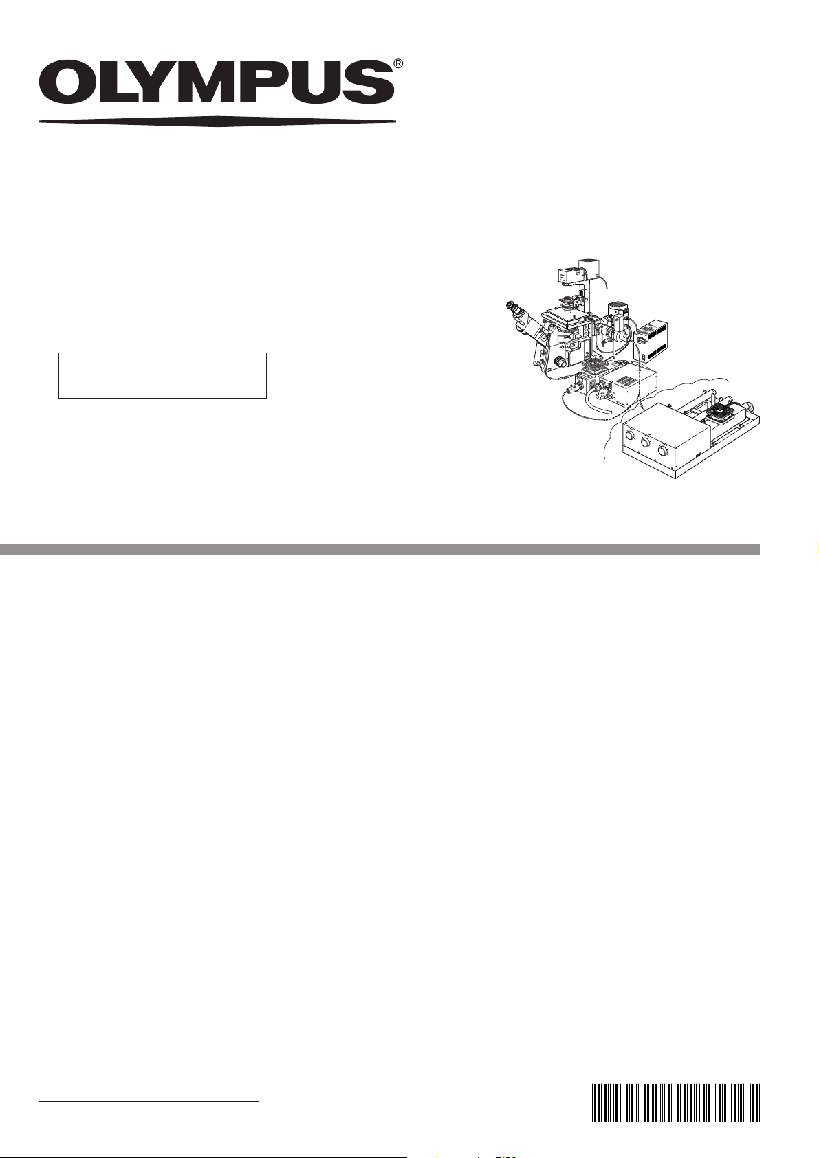
ILLUMINATION SYSTEM
INSTRUCTIONS
TOTAL INTERNAL
REFLECTION
This instruction manual is for the Olympus Total Internal Reflection Illumination System. To ensure the
safety, obtain optimum performance and to familiarize yourself fully with the use of this system, we
recommend that you study this manual thoroughly before operating the system.
This system employs a laser light source. Take special care for safety and please also read the
instruction manual for the laser light source.
Retain this instruction manual in an easily accessible place near the work desk for future reference.
AX7385
Page 2

This device complies with the requirements of directive 98/79/EC concerning in vitro diagnostic
medical devices. CE marking means the conformity to the directive.
NOTE: This equipment has been tested and found to comply with the limits for a Class A digital device,
pursuant to Part 15 of the FCC Rules. These limits are designed to provide reasonable protection
against harmful interference when the equipment is operated in a commercial environment. This
equipment generates, uses, and can radiate radio frequency energy and, if not installed and used in
accordance with the instruction manual, may cause harmful interference to radio communications.
Operation of this equipment in a residential area is likely to cause harmful interference in which case
the user will be required to correct the interference at his own expense.
FCC WARNING: Changes or modifications not expressly approved by the party responsible for compliance
could void the user’s authority to operate the equipment.
Page 3

CONTENTS
IX2-RFAEVA-2
CAUTION
This system employs a laser light source and should be assembled and adjusted by qualified
service personnel from Olympus.
Never attempt to assemble or adjust the system for it is extremely hazardous.
IMPORTANT – Be sure to read this section for safe use of the equipment. –
1 MODULE NOMENCLATURE
2 CONTROLS
TOTAL INTERNAL REFLECTION FLUORESCENCE OBSERVATION
3
3-1 Conditions of Observation...................................................................................................................................................... 11
3-2 Preparation for Observation ................................................................................................................................................ 12
1 Preparing for Laser Beam Introduction 2 Introducing the Laser Beam
3-3 Observation Procedure .............................................................................................................................................................. 13
1-7
8
9, 10
11- 14
1 Adjusting the Focus 2 Adjusting the Laser Beam Incidence Angle
4 REFLECTED LIGHT FLUORESCENCE OBSERVATION
5 USING THE CONTROLS
1 Using the Binocular Tube Shutter 2 Using the Specimen Cover
3 Field Iris Aperture Diaphram 4 Filter Slider
6 TROUBLESHOOTING GUIDE
7 SPECIFICATIONS
PROPER SELECTION OF THE POWER SUPPLY CORD............................................................. 19 , 20
15
15, 16
17
18
Page 4
IMPORTANT
This system has been designed to be used in combination with an IX2 series (IX81/IX71/IX51) or IX
series (IX70/IX50) microscope to provide it with total internal reflection fluorescence illumination* using
a laser light source.
* Total internal reflection fluorescence illumination utilizes the “evanescent light”, a very small amount of
light at the sub-micrometric order penetrating beyond the total reflection of the cover glass (on the
specimen side), to excite only the fluorescent molecules exiting near the cover glass surface. By eliminating the background fluorescence, it enables fluorescence observation with very high contrast.
LASER SAFETY PRECAUTIONS
1. The laser used in combination with this system is designated as a laser product of the following class.
CLASS IIIb (CDRH)
CLASS 3B (IEC60825-1)
A CLASS 3B laser product is permitted to be used exclusively under control of a laser safety manager. Before
using this product, read “USER’S SAFETY PROTECTION MEASURES ACCORDING TO IEC60825-1 ‘LASER PRODUCT RADIATION SAFETY STANDARD’” carefully to apply sufficient safety measures before use.
If there is any question concerning the laser product, please consult Olympus.
2. The laser beam output from the objective position or objective top lens may injure the skin exposed to it. Avoid exposing
your finger or hand to the laser beam. Also, do not output the laser beam externally by engaging a mirror in the light path,
for this is extremely hazardous if the output beam enters your eye.
3. Place the specimen horizontally on the stage. If the specimen is tilted, the laser beam may be reflected around the
microscope and cause a hazard.
4. Never remove a unit while the laser beam output, for this may cause the laser beam to be output from there. Removal of
any unit should be performed by Olympus qualified service personnel. When removal is required, please consult Olympus.
5. Be sure to cap the revolving nosepiece positions where no objective is attached.
6. Do not bend or pull excessively or step on the laser fiber cable, for this may damage the laser fiber cable and cause laser
beam leakage that is extremely hazardous. Should laser beam leakage occur, immediately turn off the laser light source
and contact Olympus.
7. The laser-cooling fans output warm winds through the air outlets. Do not place an object that is flammable or nonresistant to heat near an air outlet.
To prevent electric shock or fire hazard, be sure to consult Olympus if you want to use a remote interlock
connector.
1
Page 5
IX2-RFAEVA-2
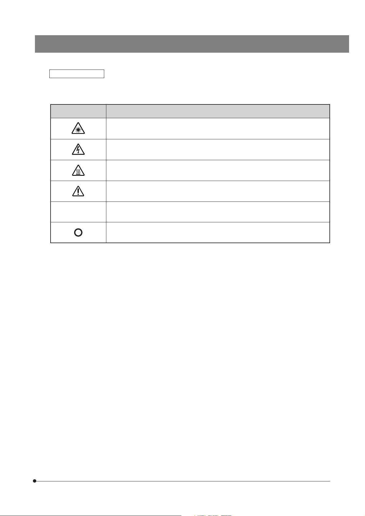
Safety Symbols
The following symbols are found on the system. Study the meaning of the symbols and always use the equipment in the
safest possible manner.
Symbol
l
Explanation
Indicates the use of a laser beam. Take special care in handling the part.
Indicates presence of a high voltage (1 kV or more). Take care against electric shock.
Indicates that the surface becomes hot, and should not be touched with bare hands.
Before use, carefully read the instruction manual. Improper use could result in personal injury
to the user and/or damage to the equipment.
Indicates that the main switch is ON.
Indicates that the main switch is OFF.
2
Page 6
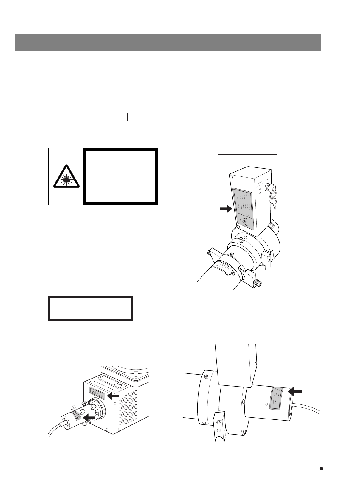
Warning Labels
Warning labels are placed at parts where special precaution is required when handling and using the system. Always
heed the warnings.
If warning labels become soiled, peel off, etc., contact your local Olympus representative to have them replaced.
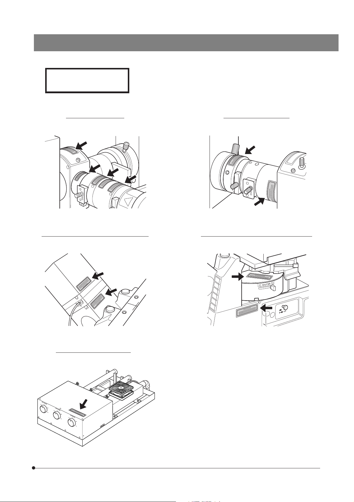
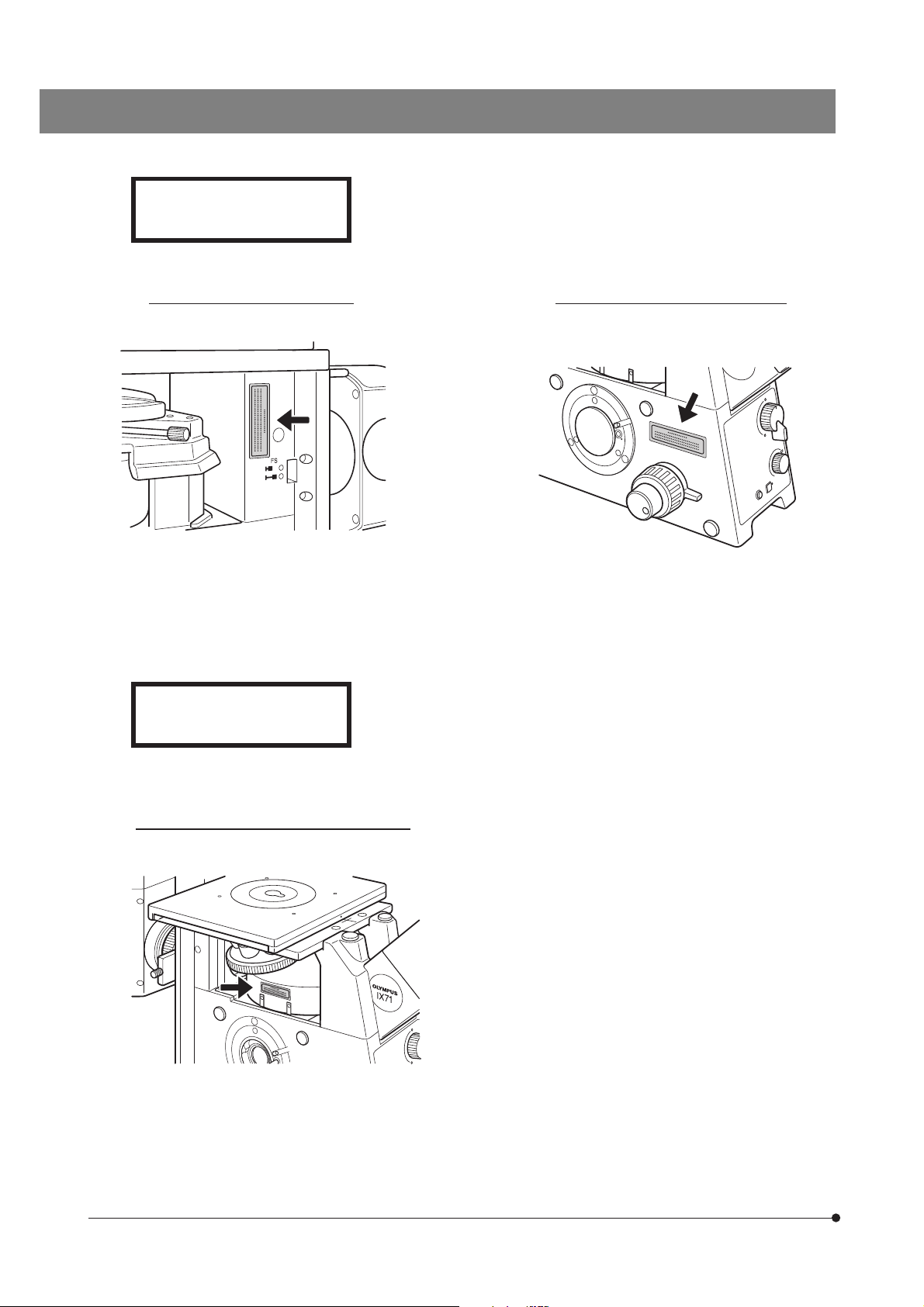
Warning Label Positions
}Warning labels are attached to the positions indicated by the arrows.
Fiber light illuminator
LASER LIGHT
AVOID EXPOSURE TO BEAM
CLASS IIIb LASER PRODUCT (CDRH)
CLASS 3B LASER PRODUCT
(IEC60825-1 : 1993+A1 : 1997+A2 : 2001)
50mW MAX CW 400-700nm
3
CAUTION-CLASS 3B
LASER RADIATION WHEN OPEN.
AVOID EXPOSURE TO THE BEAM.
Fiber light illuminator
Ar laser unit
Page 7
CAUTION-CLASS 3B
LASER RADIATION WHEN OPEN.
AVOID EXPOSURE TO THE BEAM.
Fiber light illuminator Straight light illuminator
IX2-RFAEVA-2
Binocular tube & binocular tube shutter Microscope frame & revolving nosepiece
Laser combiner IX2-COMB
4
Page 8
CAUTION-CLASS 3B
LASER RADIATION WHEN OPEN.
AVOID EXPOSURE TO THE BEAM.
Microscope frame (rear right)
AVOID EXPOSURE
LASER RADIATION IS EMITTED
FROM THIS APERTURE.
Microscope frame (left side port)
5
Microscope left side (Reflected
illumination and observation light path)
Page 9

IX2-RFAEVA-2
SAFETY PRECAUTIONS
Movement of the System
The system is assembled and set up by qualified service personnel. Avoid moving the system for this may deviate the
optical adjustments. Consult Olympus when you wish to move the system. If the system is moved by the customer,
Olympus will not assume liabilities for the system malfunctions and damage that may result.
Disposal of the System
1. The laser tube used in the system should be disposed of according to your local industrial waste disposal regulations. If
disposal by you is forbidden, please contact Olympus.
2. The mercury burner used in the illumination of the system should be disposed of according to your local industrial waste
disposal regulations.
Handling Precautions
1. After the equipment has been used in an observation of a specimen that is accompanied with a potential of
infection, clean the parts coming in contact with the specimen to prevent infection.
· Moving this product is accompanied with the risk of dropping the specimen. Be sure to remove the specimen before
moving this product.
· In case the specimen is damaged by erroneous operation, promptly take the infection prevention measures.
· The product becomes unstable if its height is increased by an accessory mounted on it. In this case, take
anti-toppling measures to prevent the specimen from being dropped when the product topples down.
2. The system is composed of precision equipment. Handle it with care and avoid subjecting it to sudden or severe impact.
3. Do not bend or pull excessively or step on the fiber cable, for this may degrade the performance considerably.
4. When the reflected light source is turned off, do not turn it again for at lease 10 minutes. Otherwise, the service life of the
mercury burner may be reduced.
5. Do not apply cool air from an air conditioner, etc., to the laser beam. Otherwise, the operation may become unstable.
6. To avoid destruction of the laser tube, absolutely avoid causing condensation in it. When the laser tube has been left
under a cold environment for a long period, condensation by avoided by not starting to warm the operation room until the
laser operation has started.
7. When a laser is not used for more than a month, it should be subjected to idle operation (aging) for more than 8
continuous hours at least every month. Otherwise, the laser oscillation may become unstable, causing sudden stopping
of oscillation during operation or shortening of service life.
8. The laser-cooling fans output warm winds through the air outlets. Do not place an object that is flammable or nonresistant to heat near an air outlet. Leave a space of 50 cm or more in front of each air outlet to facilitate heat ventilation.
(Overheating of laser tube may make the laser oscillation unstable, causing sudden stopping of oscillation during
operation. The rise in the equipment internal temperature may also cause malfunction or failure.)
9. As cooling fans are installed at the front and rear of the laser power supply, this should be installed by leaving spaces of
30 cm or more from the surrounding walls so as not to block ventilation from the cooling fans as well as from the splits
on the top and side panels. Do not leave an object such as documents or a book on the top of the laser power supply,
for this may cause overheating, which leads to sudden stopping of laser oscillation due to activation of the protection
circuitry.
. Install the system so that the power supply to the system can be shut down easily by switching the power switch or
10
unplugging the power cord from the power outlet. Also, the power supply for the system should be positioned in a place
allowing easy shutdown of the power supply.
6
Page 10

Getting Ready
1
1. This manual pertains only to the handling of the total internal reflection fluorescence illumination system. Please also
read the instruction manuals for the IX2 series (IX series) microscope and associated options to understand the
comprehensive operating instructions of the microscope system.
2. The total internal reflection fluorescence illumination system is composed of precision instruments. Handle it with care
and avoid subjecting it to sudden or severe impact.
3. Do not use the system where it is subjected to direct sunlight, high temperature and humidity, dust or vibrations.
4. Reserves spaces of 10 cm or more around the lamp housing and power supply to facilitate their ventilation.
Maintenance and Storage
2
1. To clean the lenses and other glass components, simply blow dirty away using a commercially available blower and
wipe gently using a piece of cleaning paper (or clean gauze).
If a lens is stained with fingerprints or oil smudges, wipe it gauze slightly moistened with commercially available absolute
alcohol.
Since the absolute alcohol is highly flammable, it must be handled carefully.
Be sure to keep it away from open flames or potential sources of electrical sparks –– for example, electrical
equipment that is being switched on or off.
Also remember to always use it only in a well-ventilated room.
2. Do not attempt to use organic solvents to clean the non-optical components. To clean them, use a lint-free, soft cloth
slightly moistened with a diluted neutral detergent.
3. Never attempt to disassemble any part of the system, for this may degrade the performance and the laser beam output.
Caution
3
If the system is used in a manner not specified by this manual, the safety of the user may be imperiled. In addition, the
equipment may also be damaged. Always use the equipment as outlined in this instruction manual.
The following symbols are used to set off text in this instruction manual.
: Indicates that the instructions are related to the hazard of laser beam.
: Indicates that failure to follow the instructions in the warning could result in bodily harm to the
user and/or damage to equipment (including objects in the vicinity of the equipment).
# : Indicates that failure to follow the instructions could result in damage to the equipment.
} : Indicates commentary (for ease of operation and maintenance).
7
Page 11

IX2-RFAEVA-2
1
Specimen Cover
MODULE NOMENCLATURE
? The modules enclosed ( ) belong to the IX2-RFAEVA-2 total internal reflection fluorescence illumination
system.
*Remove the excitation filter from each laser
wavelength compatible excitation mirror unit
For IX2/IX series:
· Fluorescence mirror unit cassette
· Fluorescence mirror unit (for mercury burner)
· Fluorescence mirror unit (for laser)*
Objectives
Straight light illuminator
**
*Remove the excitation filter from the IB
before use. (See the chart on page 11.)
excitation mirror unit before use. (488 nm Ar
**
For cell specimens and fluorescent molecules:
laser)
Apo100XOHR/PlanApoN60XO
**
For cell specimens:
Note1)
order)
Apo100XOHR, PlanApo60XO
For fluorescent molecules: UPlanSApo100XO/
custom order)
PlanApoN60XO
For fluorescent molecules: PlanApo100XO,
PlanApo60XO2
Note2)
For IX2/IX series:
Mercury lamp housing
TIRFM (made to
Power Supply Unit
U-RFL-T
TIRFM (made to
Binocular tube
shutter
Microscope frame
IX2 series (IX81/IX71/IX51)
IX series (IX70/IX50)
Safety interlock cable
Fiber light illuminator
Laser adapter
Fiber unit
FV5-FUR
Note 1) The PlanApo60XO
be used.
Note 2) The PlanApo100XO3 and PlanApo60XO3 for the
UIS series can also be used (ones with model
numbers 3, 2 and none are all usable).
for the UIS series can also
TIRFM
Ar laser unit
(488 nm)
FV5-LAAR
Laser power supply
FV5-LAAR
Laser combiner
IX2-COMB
Optional.
See the separate instruction
( )
manual for details.
8
Page 12

CONTROLS
Straight Light Illuminator and Fiber Light Illuminator
Laser emission indicators
ON : Laser being emitted
Illumination selector knob
: Laser light path
: Mercury burner light path
OFF : Shuttered
1
Field iris diaphragm (FS) centering screw
IX2 series adapter
Field iris diaphragm (FS) lever
Filter slider
Pushed in: Filter engaged
Pulled out: Shutter engaged
View in the direction of arrow 1
Filter slider
Pushed in : Filter
Pulled• out : Shutter
engaged
engaged
Laser incidence angle
adjustment knob
2
Laser interlock key switch
ON : Interlocked
OFF : Laser beam blocked
Support foot
View in the direction of arrow 2
Laser interlock connector
AC adapter connector
Field iris diaphragm (FS) lever
Field iris diaphragm (FS) centering screw
Binocular Tube Shutter
Shutter
Pushed in: Shutter engaged (IN)
Pulled out: Shutter disengaged (OUT)
9
User interlock cable connector
For the use of this connector,
contact Olympus.
AC Adapter
U-ACAD4515
Page 13

IX2-RFAEVA-2
Specimen Cover
?Lighting the specimen replacement lid activates the interlock key switch and the motorized shutters ( x 2) of the
fiber light illuminator blocks the laser beam.
Knobs
Specimen box
Ar Laser Power Supply (488 nm)
FV5-LAAR
Specimen replacement lid
Interlock connector
Key
Main switch
10
Page 14

TOTAL INTERNAL REFLECTION FLUORESCENCE
OBSERVATION
Because this observation method employs laser beam, be sure to observe the
following precautions.
· Never remove a part on which a warning panel is attached.
· Be sure to set the interlock key switch to OFF and make sure that the laser emission indicator
is OFF before proceeding to the objective switching or fluorescence turret switching.
3-1 Conditions of Observation
Be sure to observe the following laser operating environment conditions.
· Temperature: 18 to 28°C (performance guaranteed), 10 to 35°C (laser oscillation guaranteed).
· Humidity: 30% to 80% (without condensation)
· Excitation wavelengths: 400 to 750 nm with both laser and mercury burner.
Observe the following precautions in the total internal reflection fluorescence observation.
· Applicable objectives for total internal reflection fluorescence observation
Cell specimens and fluorescent molecules: Apo100XOHR (NA 1.65), PlanApoN60XO
Fluorescent molecules: UPlanSApo100XO (NA 1.40), PlanApoN60XO (NA 1.42).
· A special cover glass and immersion oil are required when using the Apo100XOHR.
· The total internal reflection fluorescence mirror unit can be used by removing the excitation filter of the excitation mirror unit.
TIRFM (made to order, NA 1.45).
Excitation Mirror Unit Laser (Wavelength)
IB excitation U-M)IB3
U-M)IBA3
G excitation U-M)G2 HeNe-G laser (543 nm)
U-MWIG3 Nd-YAG laser (532 nm)
U-M)IGA3
R excitation (Commercially HeNe-R laser (633 nm)
available product)
IY excitation U-MWIY2 Kr laser (568 nm)
BV excitation U-M)BV2 He-Cd laser (442 nm)
· The character(s) in ) can be SW, W or N. Type 2 excitation mirror units can also be used.
· For the multi-excitation mirror units, consult Olympus.
· For IB excitation fluorescence observation using the mercury burner, it is required to prepare a separate IB
excitation mirror unit incorporating an excitation filter, apart from the total internal reflection fluorescence mirror
unit.
· Total internal reflection observation is not available with the binocular tube light path (because the laser will not
be emitted unless the binocular tube shutter is engaged in the light path).
· The observation field number is 11.7 with both laser and mercury burner.
Ar laser (488 nm)
11
Page 15

IX2-RFAEVA-2
3-2 Preparation for Observation
Never peel off warning label from a position it is attached. Otherwise, the laser beam may enter your eyes.
²
4
@
Fig. 1
5
Preparing for Laser Beam Introduction (Fig. 1)
1
1. Set the light path selector knob of the microscope for the camera light
path.
2. Push in the illumination selector knob @ for the laser light path.
3. Rotate the fluorescence mirror unit turret to engage an excitation mirror
unit that is compatible with total internal reflection fluorescence observation.
4. Engage the objective for total internal reflection observation in the light
path.
5. Push in the shutter of the binocular tube shutter to engage it in the light
path.
6. Push in the filter slider ² of the fiber light illuminator to engage the
released shutter.
7. Release the shutter of the fluorescence mirror unit turret (by setting the
shutter to position marked “\" ).
8. Put the specimen replacement lid on the specimen box.
Introducing the Laser Beam
2
}To ensure stable laser beam output, warm up the system (for about 10
minutes) after turning the laser power supply on.
1. Set the main switch 3 to “ I ” (ON).
2. Turn the key 4 till the ON position. This also starts the laser-cooling fans.
The laser will start oscillation in about 10 seconds to 1 minute.
3. Set the laser interlock key switch (5 in Fig. 1) to ON.
(Fig. 2)
3
Fig. 2
12
Page 16

3-3 Observation Procedure
@
@
²
Fig. 3
Fig. 4
Adjusting the Focus
1
1. Remove the specimen replacement lid @ from the stage.
2. Apply immersion oil on the objective top lens and place the specimen on
the stage.
3. Place the specimen replacement lid @ on the specimen box ²; the laser
beam will be output. When the image is displayed on the monitor for the TV
camera, bring the displayed specimen image into focus.
Adjusting the Laser Beam Incidence Angle
2
}Perform the laser beam incidence angle adjustment by referring to the
“Explanation Diagrams” on the next page.
}When the laser beam incidence angle adjustment knob 1 of the fiber
light illuminator is set to the fully clockwise position, the angle of the laser
beam output from the objective is smaller than the critical angle and total
internal reflection is not obtained (see Explanation 1).
# Do not turn the adjustment knob further clockwise from the above
condition by force.
1. While observing the monitored image, turn the adjustment knob 1 slowly
counterclockwise until total internal reflection fluorescence is obtained
(Explanation 3).
(Fig. 3)
(Fig. 4)
When the laser incidence angle approaches the critical angle (Explanation 2), the bright part of the fluorescence image flows in the
vertical or horizontal direction of the field of view. When the angle
is increased further, the background fluorescence darkens suddenly and the total internal reflection fluorescence is obtained (Explanation 3).
2. Turning the adjustment knob 1 further counterclockwise decreases the
range where total internal reflection fluorescence is observed (depth from
the cover glass surface). Turning the adjustment knob clockwise increase
the above range.
}If the adjustment knob is turned too much counterclockwise, nothing will
be visible eventually (Explanation 4).
13
Page 17

Explanation Diagrams (Laser Beam Incidence Angle Adjustment)
Explanation 1 : Condition before laser incidence angle adjustment
IX2-RFAEVA-2
Glass
Laser beam
· The laser beam is transmitting through the
glass and specimen.
Specimen
Immersion oil
Objective
Explanation 2 : Critical angle condition
· The laser beam travels on the upper surface of the glass.
Monitored image
Field iris diaphragm
image
Fluorescence image
of specimen
· The fluorescence image of specimen is observed even
when it is defocused by moving the objective upward.
· The image flows in the horizontal direction (also in the
vertical direction depending on the camera installation orientation).
Explanation 3 : Total internal reflection condition
· When total internal reflection is achieved, the reflected
laser beam returns to the objective and forms an evanescence field on the glass.
Explanation 4 : Condition before laser incidence
· The laser beam hits the inner frame of objective and
does not reach the specimen.
· The image darkens
suddenly.
· The focused plane
is thin.
· The fluorescence image of specimen becomes invisible
when it is defocused by moving the objective upward.
· The image is
completely dark.
· When the camera gain is increased, vague light may be
visible due to the stray light.
14
Page 18

REFLECTED LIGHT FLUORESCENCE OBSERVATION
(Observation Using the Mercury Burner)
}Follow the instructions given by the instruction manual for the reflected light fluorescence system in use.
For this observation, be sure to attach the original fluorescence mirror unit, which incorporates the excitation filter,
to the turret.
USING THE CONTROLS
@
@
²
Fig. 5
Fig. 6
1 Using the Binocular Tube Shutter
}When the shutter @ of the binocular shutter is pulled out, the laser inter-
lock key switch is activated, blocking the laser beam output and, for
safety, making the total internal reflection observation unavailable for the
binocular tube.
1. To observe the specimen through the binocular tube, pull out the shutter
@ to open the light path.
In this case, the laser beam is not output because it is blocked by the
motorized shutter.
2. To perform total internal reflection observation, push in the shutter @ all
the way until it is stopped.
This activates the laser interlock key switch, causing the laser beam to be
output.
Using the Specimen Cover
2
}Removal of the specimen replacement lid @ activates the laser interlock
key switch and blocks the laser beam output.
1. For transmitted light observation or for changing the specimen, remove
the specimen replacement lid @.
In this case, the laser beam is not output because it is blocked by the
motorized shutter.
2. To perform total internal reflection observation, place the specimen
replacement lid @ on the specimen box 2.
This activates the laser interlock key switch, causing the laser beam to be
output.
# When a condenser with short working distance (IX2-LWUCD, IX2-
LWUCDA2, IX2-DICD or U-UCD8) is used, push down the transmitted
light illumination column toward the rear or swing the condenser
holder upward in advance.
(Fig. 5)
(Fig. 6)
15
Page 19

IX2-RFAEVA-2
@
²
³
Fig. 7
Fig. 8
Field Iris Aperture Diaphragm
3
}To prevent progress of specimen fading, stop down the field iris aperture
diaphragm to cover only the observed area.
· The field iris diaphragm can be stopped down by pulling out the field iris
diaphragm lever @.
Centering the Field Iris Diaphragm (Figs. 7 & 8)
1. Place a specimen on the stage and bring the specimen image displayed
on the monitor into focus.
2. Pull out the field iris diaphragm lever @ so that the field iris diaphragm
image ² is displayed on the monitor screen.
3. Insert the Allen screwdriver, provided with the microscope frame, alternately into the two centering screws ³ to bring the field iris diaphragm
image ² at the center of the monitor screen.
4. After completing centering, push in the field iris diaphragm lever @ until
the field iris diaphragm image ² circumscribes the monitor screen.
}If the TV camera uses image pickup devices that are larger than 2/3 inch,
the field iris diaphragm image will not circumscribe the monitor screen
even when the field iris diaphragm is opened at maximum.
(Fig. 7)
@
Fig. 9
@
Filter Slider
4
}The filter slider has the same structure with both the straight light illumina-
tor and fiber light illuminator, allowing either the shutter or filter pocket to
be engaged in the light path according to the left and right sliding of the
slider.
}When observation is not performed, engage the shutter in the light path
to prevent the specimen from fading.
1. Pull out the filter slider @ in the direction of the arrow to engage the
shutter in the light path.
2. The filter pocket accepts brightness adjustment ND filters, which can be
dropped into the pocket for insertion.
· Up to five ND filters, including the 32ND6, 32ND12, 32ND25 and 32ND50
can be inserted.
If the ND filters in the fiber light illuminator are tilted, irregularities due
to interference of laser beam may be observed in the field of view. To
prevent this, keep the ND filters vertical by means of the ring spring
inside the filter pocket.
The filter slider becomes very hot when the system has been on for a
long period. Be careful not touch the filter slider parts other than the
knob.
(Fig. 9)
16
Page 20

TROUBLESHOOTING GUIDE
Caution
Never look into an objective
to check if the laser beam is
output.
Remedy
Be sure to pulled out the shut-
ter to block the laser beam be-
fore proceeding to treatment.
Be sure to pulled out the shut-
ter to block the laser beam be-
fore proceeding to treatment.
If the interference stripe does
not disappear after treatment,
please consult Olympus.
Push in the illumination selector knob to select the laser
illuminator light path.
Set the main switch and key of the laser oscillator to ON.
Push in the filter slider to open the light path.
Release the manual shutter.
Engage a total internal reflection fluorescence mirror unit
in the light path.
Turn the laser beam incidence angle adjustment knob all
the way clockwise.
Cause
The illumination selector knob is set for the mer-
cury burner illuminator.
The manual shutter of the fluorescence mirror unit
cassette is closed.
Other fluorescence mirror unit than a total internal
reflection fluorescence mirror unit is engaged in
the light path.
The laser beam incidence angle adjustment knob
The filter slider of the fiber light illuminator is pulled
The laser oscillator is not ON.
Problem
out.
is turned too much counterclockwise.
Set the interlock key switch to ON.
Push in the binocular tube shutter.
Place the specimen replacement lid on the specimen
box.
The interlock key switch is set to OFF.
The specimen replacement lid is removed.
The binocular tube shutter is pulled out.
Connect it properly.
The AC adapter connector is connected im-
Turn the laser incidence angle adjustment knob counter
clockwise.
Turn the laser beam incidence angle adjustment knob
clockwise.
Engage a total internal reflection fluorescence objective in
the light path.
Place the cover glass so that it is parallel with the stage
center plate.
Use the Apo100XOHR objective (NA 1.65) to observe a speci-
Wait until the laser beam is output.
properly.
The laser incidence angle is not the critical angle.
The equipment is normal if the laser beam is out-
put within about 1 minute.
An objective other than the total internal reflection
fluorescence objective is engaged in the light path.
The laser beam incidence angle adjustment knob
is turned too much counterclockwise.
men with a refractive index of 1.38 (index of cytoplasm) or
The specimen being observed has a refractive
index of 1.38 or more (glycerin sealed specimen,
The specimen is tilted.
Stand the ND filter vertically using the ring spring provided
Special immersion oil and cover glass are required when
using the Apo100XOHR (NA 1.65).
more.
etc.)
The immersion oil or cover glass is not suitable.
The ND filter in the filter slider is tilted.
in the filter slider.
If the interference stripe still does not disappear, rotate the
Put the specimen (cell) in close and perfect contact with
the cover glass.
Engage a total reflection fluorescence mirror unit without
excitation filter in the light path.
ND filter to minimize the interference stripe.
A fluorescence mirror unit incorporating an excita-
tion filter is engaged in the light path.
Wipe off the immersion oil and attach new oil by avoiding
bubble penetration.
The specimen (cell) is not in close contact with
the cover glass but is separated from it at some
positions.
The immersion oil contains bubbles.
The objective is dirty. Clean the objective top lens with the cleaning mixture fluid.
Blow dust away using a blower, etc.
Dust is attached to the dichroic mirror or barrier
filter.
17
No laser beam is output.
Classification
Laser beam
output
Total internal reflection fluorescence cannot
be obtained.
It takes long time after the laser oscillator is
switched ON till the laser beam is output.
Laser beam
observation
Linear or elliptical interference stripes are
observed in the field.
Random interference stripe is observed in the
field, and the stripe moves when the stage is
moved.
Random interference stripe is observed in
the field, and the stripe does not move even
when the stage is moved.
An interference stripe with a concentric pat-
tern is observed.
Page 21

SPECIFICATIONS
Item Specification
Applicable microscope frames
Applicable reflected fluorescence
systems
Total internal reflection illumination
system
IX2-RFAEVA
Ar laser unit/power supply
FV5-LAAR
Operating environment
Storage environment
IX2-RFAEVA-2
· IX2 series (IX81/IX71/IX51)
· IX series (IX70/IX50)
· IX2 and IX series systems
(Reflected light illuminator unnecessary)
Straight (mercury burner)/Fiber light (laser) double illuminator
· Either illuminator can be selected using the illumination selector
knob.
· Interlock mechanism (Laser interlock/User interlock).
· Field iris diaphragm (Diameter adjustable between 1.7 and 13 mm)
· Filter slider
· Maximum FN 11.7
· Interlock key switch
· Laser emission indicators
Binocular tube shutter
· Laser interlock mechanism with the binocular tube shutter.
(Releasing the shutter engages the shutter in the laser light path.)
Specimen cover
· Laser interlock mechanism with the specimen replacement lid.
(Removing the specimen replacement lid engages the shutter in
the laser light path.)
· 10 mW power, linear polarization
· Forced air-cooled Ar ion laser (488 nm)
· Connection with the fiber light illuminator: Polarization plane saving
fiber cable FV5-FUR (3 m)
· Power consumption: 115 V, 10 A (max.)
230 V, 10 A (max.)
· Indoor use
· Altitude: Max. 2000 m
· Temperature: 18 to 28°C (performance guaranteed), 10 to 35°C (laser
oscillation guaranteed)
· Relative humidity: 30% 80% (without condensation)
· Supply voltage fluctuations: ±10%
· Pollution degree: 2 (in accordance with IEC60664)
· Installation (overvoltage) category: II (in accordance with IEC60664)
· Temperature: –25 to 65°C
· Relative humidity: 10% to 90%
Safety
EN61010-1(1993 +A2 1995): Safety requirements for electrical equipment for measurement, control and laboratory
use.
EN60825-1(1994 +A2 2001): Safety of laser products.
Electromagnetic Compatibility
EN61326(1997 +A1 1998): Electrical equipment for measurement, control and laboratory use EMC requirements.
EN61326 defines two categories according to the location for use.
Class A: Equipment suitable for use in establishments other than domestic, and those directly connected
to a low voltage power supply network which supplies buildings used for domestic purposes.
Class B: Equipment for use in domestic establishments, and in establishments directly connected to a low
voltage power supply network which supplies buildings used for domestic purposes.
This system is applied Class A. Some interference may occur if this system is used in domestic location.
18
Page 22

PROPER SELECTION OF THE POWER SUPPLY CORD
If no power supply cord is provided, please select the proper power supply cord for the equipment by referring to “Specifications”
and “Certified Cord” below:
CAUTION: In case you use a non-approved power supply cord for Olympus products, Olympus can no longer warrant
the electrical safety of the equipment.
Specifications
Voltage Rating
Current Rating
Temperature Rating
Length
Fittings Configuration
125V AC (for 100-120V AC area) or, 250V AC (for 220-240V AC area)
6A minimum
60°C minimum
3.05 m maximum
Grounding type attachment plug cap. Opposite terminates in molded-on IEC configuration appliance coupling.
Table 1 Certified Cord
A power supply cord should be certified by one of the agencies listed in Table 1, or comprised of cordage marked with
an agency marking per Table 1 or marked per Table 2. The fittings are to be marked with at least one of agencies listed
in Table 1. In case you are unable to buy locally in your country the power supply cord which is approved by one of the
agencies mentioned in Table 1, please use replacements approved by any other equivalent and authorized agencies
in your country.
Country Agency
Argentina IRAM
Australia SAA Japan
Certification
Mark
Country Agency
Italy IMQ
JET, JQA, TÜV,
UL-APEX / MITI
Certification
Mark
19
Austria ÖVE Netherlands KEMA
Belgium CEBEC Norway NEMKO
Canada CSA Spain AEE
Denmark DEMKO Sweden SEMKO
Finland FEI Switzerland SEV
France UTE
Germany VDE U.S.A. UL
Ireland NSAI
United
Kingdom
ASTA
BSI
Page 23

Table 2 HAR Flexible Cord
APPROVAL ORGANIZATIONS AND CORDAGE HARMONIZATION MARKING METHODS
IX2-RFAEVA-2
Approval Organization
Comité Électrotechnique Belge
(CEBEC)
VDE Verband der Elektrotechnik
Elektronik Informationstechnik e.V.
Union Technique de l’Électricité
(UTE)
Istituto Italiano del Marchio di Qualità
(IMQ)
British Approvals Service for Cables
(BASEC)
N.V. KEMA KEMA-KEUR <HAR> 10 30 30
SEMKO AB Svenska Elektriska
Materielkontrollanstalten
Österreichischer Verband für
Elektrotechnik (ÖVE)
Danmarks Elektriske Materielkontrol
(DEMKO)
Printed or Embossed Harmonization
Marking (May be located on jacket
or insulation of internal wiring)
CEBEC <HAR> 10 30 10
<VDE> <HAR> 30 10 10
USE <HAR> 30 10 30
IEMMEQU <HAR> 10 30 50
BASEC <HAR> 10 10 30
SEMKO <HAR> 10 10 50
<ÖVE> <HAR> 30 10 50
<DEMKO> <HAR> 30 10 30
Alternative Marking Utilizing
Black-Red-Yellow Thread (Length
of color section in mm)
Black Red Yellow
National Standards Authority of Ireland
(NSAI)
Norges Elektriske Materiellkontroll
(NEMKO)
Asociación Electrotécnica Española
(AEE)
Hellenic Organization for
Standardization (ELOT)
Instituto Português da Qualidade (IPQ) np <HAR> 10 10 90
Schweizerischer Elektrotechnischer
Verein (SEV)
Elektriska Inspektoratet SETI <HAR> 10 30 90
Underwriters Laboratories Inc. (UL) SV, SVT, SJ or SJT, 3 X 18AWG
Canadian Standards Association (CSA) SV, SVT, SJ or SJT, 3 X 18AWG
<NSAI> <HAR> 30 30 50
NEMKO <HAR> 10 10 70
<UNED> <HAR> 30 10 70
ELOT <HAR> 30 30 70
SEV <HAR> 10 30 90
20
Page 24

EC REP
Shinjuku Monolith, 3-1, Nishi Shinjuku 2-chome, Shinjuku-ku, Tokyo, Japan
Wendenstraße 14-18, 20097 Hamburg, Germany
3500 Corporate Parkway, P.O. Box 610, Center Valley, PA 18034-0610, U.S.A.
One Corporate Drive, Orangeburg, NY 10962, U.S.A.
491B River Valley Road, #12-01/04 Valley Point Office Tower, Singapore 248373
31 Gilby Road, Mount Waverley, VIC., 3149, Australia
Blue Lagoon Drive, Suite 290 Miami, FL 33126, U.S.A.
5301
01/10
 Loading...