


Maintenance Manual
for maintenance engineer
CX21
Thank you for purchasing the Olympus microscope CX21.
In order to fully utilize its performance and secure optimum condition, please read this manual before
maintenance work.
Please also keep it at hand during maintenance as well as for future reference.
All rights reserved, Reproduction in whole or in part without written permission is prohibited.

CX21 MAINTENANCE MANUAL
INTRODUCTION
The purpose of this manual is to satisfy any requirements for maintenance material that maybe
considered as necessary to professionals in the maintenance field, such as Maintenance engineer
in Hospitals.
It is intended to be used as a tool for performing basic maintenance procedures if needed or when
required as per the recommended maintenance schedule.
The sections from this manual only cover procedure pertaining maintenance ’s that are considered
to be easily performed. For more involved maintenance’s or repairs, it is recommended that you
contact a qualified service engineer from your local Authorized Olympus dealer.
Maintenance parts, grease, and other items specified in the manual can be ordered from your
Authorized Olympus dealer, and subject to change without notice.
The recommended maintenance schedule is shown below as reference. ( * Necessary item)
Portion Cleaning Optical/mechanical check Maintenance schedule
Optical components
1) Outer surface
Eyepiece, objective ,
condenser lens, filter,
2) Inner part Prism,
internal lenses
Appearance
Microscope frame,
mechanical part
Observation tube
Mechanical part
Focusing unit, stage,
revolving nosepiece,
aperture iris diaphragm
*
*
*
*
Optical adjustment :
1) Optical axis (standard)
2) Left/right optical axis
3) Revolving axis
4) Parfocality
*
Mechanical movement :
Grease replacement
Mechanical adjustment
Once in a year
(If dirt is conspicuous or oil
immersion objec tive is used,
cleaning should be made after
every use.)
Once in a year
Once in a year
(If dirt is conspicuous, cleaning
should be made after every
use.)
Once in a year
Once in two to three years

CX21 MAINTENANCE MANUAL
CONTENTS
CHAPTER 1 MAINTENANCE PROCEDURE........................................................................ 1
1. Maintenance of Microscope............................................................................................ 1
2. Guide to Maintenance.................................................................................................... 2
2-1 Overview of maintenance....................................................................................... 2
2-2 Cleaning method for the optical components.......................................................... 3
3. Preparing for Inspection................................................................................................. 6
4. CX 21 Inspection Sheet...................................................................................................7
CHAPTER 2 INSPECTION PROCEDURE............................................................................. 8
1. Checking Performance of Microscope............................................................................ 8
2. Checking Dirty Portion.................................................................................................... 8
2-1 Image influence caused by dirt on each component............................................... 8
2-2 How to find dirty portion through observation.......................................................... 9
2-3 How to check cleaning condition .......................................................................... 10
CHAPTER 3 REPAIR PROCEDURE.....................................................................................11
1. Optical Adjustment ........................................................................................................11
2. Mechanical Adjustment................................................................................................. 14
2-1 Preparation for the tension adjustment of X/Y-wire................................................ 14
2-2 Adjustment method for the tension of X -wire.........................................................15
2-3 Adjustment method for the tension of Y-wire......................................................... 15
2-4 Final adjustment................................................................................................... 16
3. Replacing Grease for Coarse/Fine Adjustment Knob Ass’y........................................... 17
4. Replacing Circuit Board................................................................................................ 18
4-1 CX 21 wiring diagram............................................................................................ 18
4-2 Replacement of circuit board / socket................................................................... 18
5.
Replacing Pinion Ass'y of Plane Stage......................................................................... 19
CHAPTER 4 JIGS AND TOOLS / GREASES ..................................................................... 20
1. List of Jigs and Tools.................................................................................................... 20
2. List of Greases............................................................................................................. 20
CHAPTER 5 MAINTENANCE PARTS................................................................................... 1
1. List of Maintenance Parts............................................................................................... 1
CX21 MAINTENANCE MANUAL MAINTENANCE PROCEDURE
CHAPTER 1
MAINTENANCE PROCEDURE
1. Maintenance of Microscope
1) Fundamental handling
a. Read the instruction manual thoroughly, handle the microscope correctly.
b. Be sure to make a usual cleaning, especially after every use of microscope.
c. When handling the microscope, do not expose it to shock, moisture, heat and dust.
d. If the problem occurs, do not treat it in self-judgement.
2) Using and storing conditions
a. The microscope should be used under no vibration.
If it is placed in such environment as vibration, this causes disturbance and fatigue in
observation.
b. It should not be stored in high humidity.
Such condition causes fungus, corrosion on lens and rust on metal part.
Therefore, special caution is exercised if stored in a long period of time.
c. Intense temperature change should be avoided.
Be careful not to place the microscope near window exposed to direct sunlight and air
conditioner. When bringing it into warm room from cold storage location in winter,
condensation occurs on lens and metal part, it causes fungus and rust.
d. It should be kept clean.
The microscope is required to keep away from dust that causes contamination, fungus
on lens and failure of sliding part in the frame.
Be careful not to place it in the environment where the corrodent chemicals such as
hydrogen sulfide, hydrogen fluoride and acid are handled.
<Reference> fungus: occurrence conditions
Temperature
Dry blue aspergillus
Degree(C)
40
30
Humidity
%
60 70
- 1 -
80
Aspergillus
20
10
90
100
CX21 MAINTENANCE MANUAL MAINTENANCE PROCEDURE
with the soft brush. If there are stains on
Remove the eyepieces and objectives,
solution. (When removing the objective,
Wipe off any dirt spots on the surface of
Take off the mechanical stage from the
Clean the surface of stage and filter on
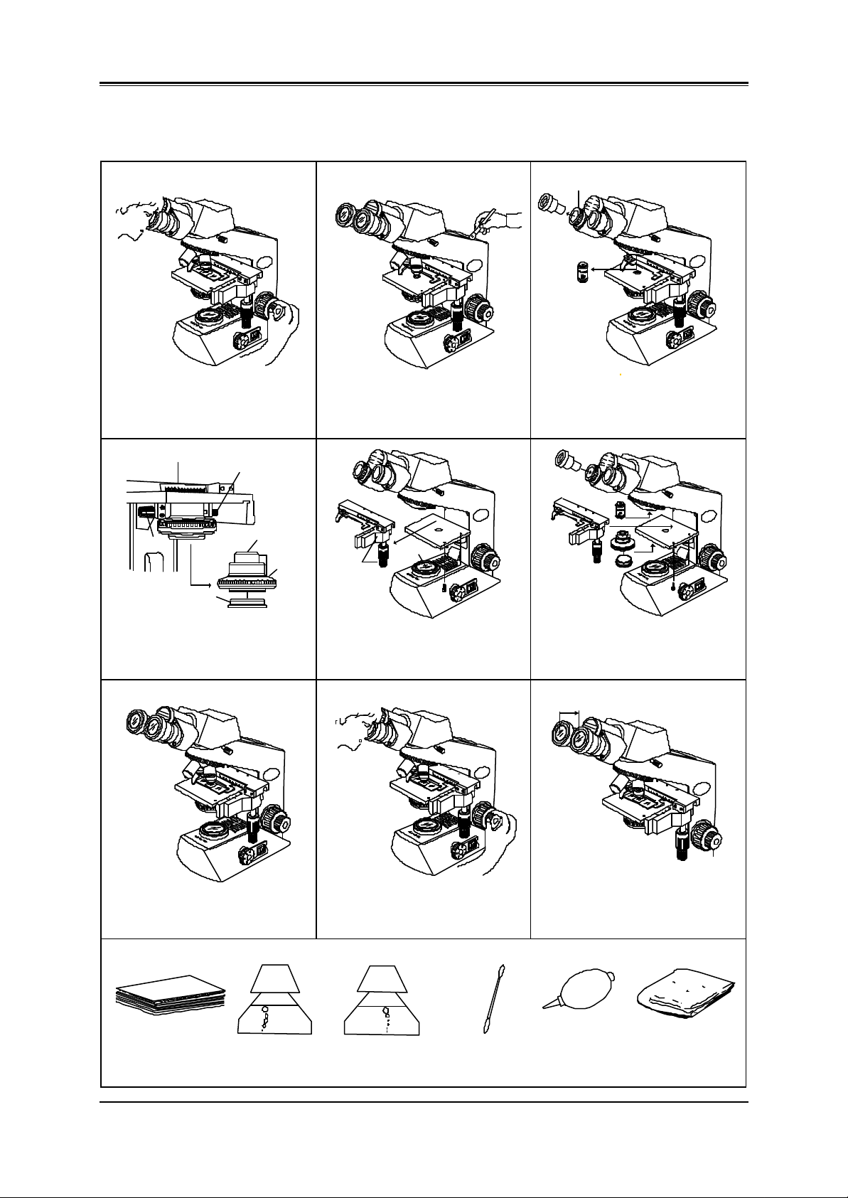
2. Guide to Maintenance
2-1 Overview of maintenance
1)
100
Set your correct interpupillary distance.
Note any areas suggesting a need for
mechanical and/or optical maintenance
by operating it or observing a specimen.
4)
(A)
Turn knob (A).
Remove it from groove.
Filter
( plastic )
Remove the condenser downward.
top lens, filter. The plastic parts should
be cleaned with netural detergent.
OLYMPUS
CX21
110
120
130
140
150
160
17
30
20
10
0
Top lens
(glass)
Plastic
7)
2)
100
Sweep off dust on the outer surfaces
the microscope frame, clean them with
neutral detergent.
5)
Plastic
75
70
60
50
100
110
120
130
140
150
160
17
30
20
10
0
glass
plane stage by removing two screws.
the base cover.
OLYMPUS
110
CX21
120
130
140
150
160
17
30
20
10
0
OLYMPUS
CX21
8)
3)
Loosen the screw securing eyepiece.
75
70
60
50
100
OLYMPUS
110
CX21
120
130
140
150
160
17
30
20
10
0
then clean their lenses with cleaning
use the rubber band.)
6)
75
70
60
50
100
110
120
130
140
150
160
17
30
20
10
0
OLYMPUS
CX21
Mount the removed components and
mechanical stage to the frame.
9)
100
OLYMPUS
CX21
110
120
130
140
150
160
17
30
20
10
0
Polish all plastic components and the
frame with silicon cloth.
Tool required:
Lens tissue Neutral detergent
(For plastic part or
frame)
100
OLYMPUS
CX21
110
120
130
140
150
160
17
30
20
10
0
Return the interpupillary distance to
original condition and prepare for the
inspection. (see page 6)
Cleaning solution
(For lens or filter
etc.)
Cotton swab
or tweezers
etc.
- 2 -
100
110
OLYMPUS
CX21
120
130
140
150
160
17
30
20
10
0
Do a final check following the inspection
sheet in this manual. (See page 7)
Blower Silicon cloth
(For finishing)
CX21 MAINTENANCE MANUAL MAINTENANCE PROCEDURE
Put it on the desk
2-2 Cleaning method for the optical components
Required tools:
1) Lens tissue
2) Cotton swab or tweezers etc.
3) Blower
4) Magnifier (Eyepiece is possible to be used by turning it upside down. Refer to page 10.)
5) Cleaning solution: e.g. Alcohol
Before cleaning: Lightly brush the lens surface or blow with the blower before wiping with tissue.
This removes particles that may scratch the lens surface. (to protect the lens
coating)
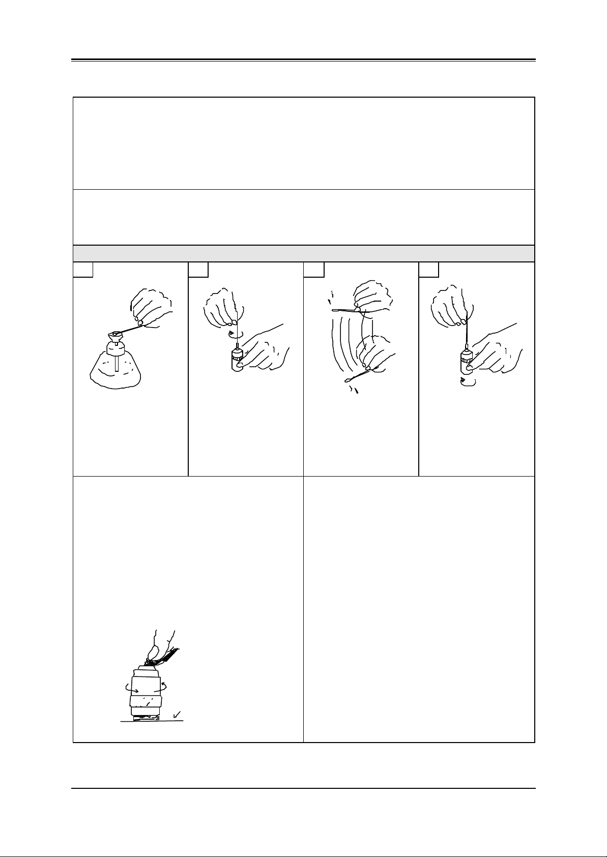
HOW TO CLEAN THE OBJECTIVE LENS
1 2 3 4
Moisten the tip of
cotton swab with
cleaning solution.
When the lens size is large and difference in level
between the lens and the lens frame is small:
Fold the lens tissue several times and moisten it
with cleaning solution.
After that, apply the folded line edge to the center
of lens, push it with index finger and turn the
objective by the other hand to clean the lens
while moving it from the center towards the
periphery.
With a circular motion,
wipe the top lens
surface with the cotton
swab, to thoroughly
remove any oil or dirt
from the lens.
Dip a new cotton swab
in the cleaning solution
and shake vigorously
to remove any excess
cleaning solution.
Cleaning the immersion objective:
Wipe off the immersion oil while absorbing it with
lens tissue that is not moistened. After that, clean
the lens as the same manner mentioned on the
left. When the top surface of lens frame is higher
than that of lens and remained dirty portion on
the periphery of lens can not be wiped off, clean
the lens referring the above figures, 1 to 4.
Wipe the objective lens
from the center
towards the periphery,
while rotating the lens.
- 3 -
CX21 MAINTENANCE MANUAL MAINTENANCE PROCEDURE
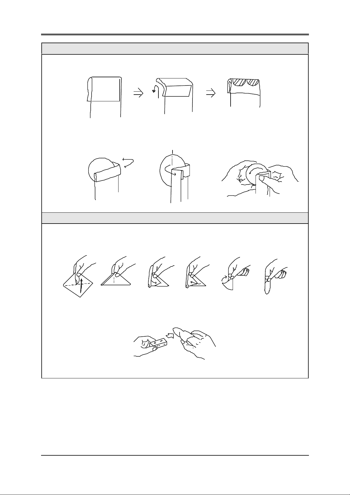
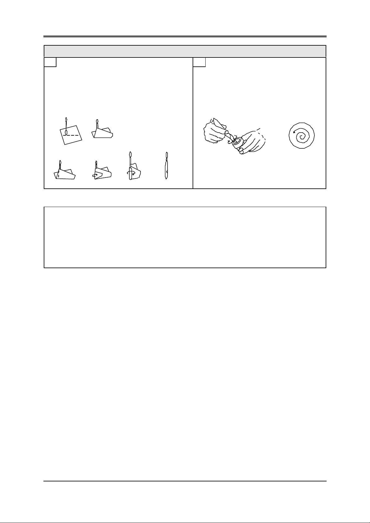
HOW TO CLEAN THE FILTER
Fold the lens tissue into two or three layers and moisten its shaded part with cleaning solution.
Hold the filter at its edge and fold the lens paper from the lens center to outside as illustrated.
Move the lens tissue gradually to outside while turning the filter by left hand.
HOW TO CLEAN THE PRISM
Hold a sheet of lens tissue between your middle and index fingers, then fold and wrap it around your
index finger. Hold the tissue down with your thumb and moisten it with sufficient cleaning solution.
1)
2) 3)
4)
Wipe the prism surfaces from front to backward at a stroke, applying even pressure.
5)
6)
- 4 -
CX21 MAINTENANCE MANUAL MAINTENANCE PROCEDURE
HOW TO CLEAN THE EYEPIECE
1 2
Wrap a sheet of lens tissue around a cotton swab
as illustrated. If the area to be cleaned is large,
wrap the lens tissue looser and thicker. Otherwise,
make a thin, tight wrap.
Dip the wrapped lens tissue in the cleaning
solution, and wipe the eyepiece from the
center towards the periphery in a circular
motion.
Important notes:
1) Never rub the lens surface strongly.
2) Do not use the same lens tissue to clean more than one lens.
3) Do not moisten the lens tissue with an excessive amount of cleaning solution.
4) When cleaning with tweezers, be careful not to protrude its tip from the lens tissue.
- 5 -

CX21 MAINTENANCE MANUAL MAINTENANCE PROCEDURE
4x10x
3. Preparing for Inspection
1) Set the main switch “A” to “I” (ON).
2) Adjust the brightness by turning the adjustment knob “B” .
3) Place a specimen on the stage.
4) Engage the 10X objective in the light path.
5) Rotate the condenser height adjustment knob ”C” to move the condenser to the highest position.
* The condenser is usually used in the highest position. If the entire observed field of view is
not bright enough, brightness may be improved by lowering the condenser slightly.
6) Looking through the eyepiece in the right sleeve without the diopter adjustment ring, turn the
coarse and fine focus adjustment knobs “D” to bring the specimen into focus.
7) Looking through the eyepiece in the left sleeve with the diopter adjustment ring, turn only the
diopter adjustment ring “E” to focus on the specimen.
(At this time, adjust the interpupillary distance so that the binocular visions on the left and right
fields of view coincide completely.)
8) Adjust the aperture iris diaphragm;
Since the aperture irirs diaphragm has an objective magnification scale (4X, 10X, 40X,100X),
rotate the diaphragm ring “F” so that the magnification scale corresponding to the objective
in use faces frontward.
(E)
(C)
(F)
100
110
120
130
140
150
160
30
20
10
0
OLYMPUS
CX21
17
(D)
(A)
(B)
- 6 -

CX21 MAINTENANCE MANUAL MAINTENANCE PROCEDURE
4. CX21 Inspection Sheet
Model : Check Date :
S/N : Checking by :
Check Point Check Contents Result Ref. Page
1. Electrical unit 1) When the power switch is turned on, the lamp is lit
and the brightness can be varied by adjustment
knob.
2. Coarse/fine focus
adjustment knob
3. Stage
4. Observation tube
5. Revolving
nosepiece
6. Condenser 1) The vertical movement of condenser is smooth. OK / NO
1) The coarse/fine focus adjustment knob is
smoothly moved without any stress or
unevenness.
2) The tension of coarse focus adjustment knob can
be adjusted by the adjustment ring.
3) The upper limit is changed by turning the stopper
on the upper side
1) The plane stage should not fall spontaneously. OK / NO
2) A specimen is held securely by the specimen
holder.
3) The X/Y movement of mechanical stage is
smooth without unevenness, backlash or slipping.
1) The interpupillary distance adjustment can be
operated smoothly in working range.
2) When changing the interpupillary distance, the
displacement of optical axis is not apparent.
3) The diopter adjustment ring is moved smoothly in
working range.
4) The optical axis of left side coincides with that of
right side.
1) The revolving nosepiece can be rotated smoothly
and stops at the click position.
OK / NO 18
OK / NO 17
OK / NO
OK / NO
OK / NO
OK / NO 15
OK / NO
OK / NO
OK / NO
OK / NO 11, 12, 13
OK / NO
(Observation)
Remarks:
1) Observation image is normal.
Without flares /ghosts / vignetting /uneven
illumination
2) Dust and dirt are not noticeable in observation . OK / NO 8, 9
OK / NO7. Visibility
- 7 -

CX21 MAINTENANCE MANUAL INSPECTION PROCEDURE
CHAPTER 2
INSPECTION PROCEDURE
1. Checking Performance of Microscope
Using the CX21 inspection sheet (P.7), check the electrical unit, mechanical and optical
performance.
2. Checking Dirty Portion
2-1 Image influence caused by dirt on each component
The following figure shows the influence of image on each optical component if stains
or dust is adhered to that portion.
In general, the microscope image is largely affected by dirt adhered on the nearer
portion to a specimen and image surfaces.
Therefore, the optical components should be kept clean and dust-free.
B Eyepiece
D Objective
A Specimen
B Condenser lens
B or A Glass
(Frosted : underside)
C Frosted glass
C Collector lens
C Prism
A: Dirt is clearly seen.
B: Blurred contours of dirt is seen.
C: Dirt is seen when the aperture iris diaphragm is stopped down.
D: Dirt is not directly seen, but contrast of image deteriorates.
- 8 -

CX21 MAINTENANCE MANUAL INSPECTION PROCEDURE
2-2 How to find dirty portion through observation
1) Close the aperture iris diaphragm.
(When the aperture iris diaphragm is closed, it facilitates finding the dirt particles
because the depth of focus increases and the dirt position bring into focus. However,
very small dirt particle may not be found in this method.)
2) Observe a specimen through the eyepiece.
If dirt is seen by observing it, look for the portion where stains or dust is adhered by
following the description below.
Check it by rotating the eyepiece
after clamping screw is loosened.
(Wipe carefully and gently so as
not to damage the lens coating.)
Objective
Dirt is not directly seen, but
dirt and dust particles affect
the microscope image.
100
110
120
130
140
150
160
17
30
20
10
0
OLYMPUS
CX21
Specimen
Check it by moving the stage.
Condenser
Eyepiece
Check the top lens and filter if
conspicuous dirt is not seen.
Collector lens part
Check it if conspicuous dirt
is not seen.
(Dust and dirt particles here
have minimal effect on the
image. However, the overall
appearance requires inside
lens cleaning.)
Note: If dirty portion can not be identified in the above, it is assumed that internal lens and
prism are contaminated.
In this case, please contact your Authorized Olympus dealer.
- 9 -

CX21 MAINTENANCE MANUAL INSPECTION PROCEDURE
2-3 How to check cleaning condition
1) When a large lens is checked, look at the lens while putting it toward bright side or
breathe on the lens and observe the condition that the haze on the whole surface of
the lens disappears evenly.
Light
Dust becomes conspicuous when
looking at it with the lens
inclination changed.
2) For a small lens such as top lens of objective, check it by magnifier.
If there is a dirty part or a remained part that
is not cleaned completely, the haze of this
part will disappear slower than that of the
other part.
An eyepiece can be substituted for
magnifier by turning the eyepiece upside
down.
- 10 -

CX21 MAINTENANCE MANUAL REPAIR PROCEDURE
CHAPTER 3
REPAIR PROCEDURE
1. Optical Adjustment
PREPARATION
*Eyepiece
for CX21
*It is necessary to set the
cross micrometer disk to
the above eyepiece.
Adjusting the left/right optical axis
If the left/right optical axis is remarkably displaced at
checking, perform the following adjustment.
*Insert the cross eyepiece
into the right sleeve.
Objective 10X
Specimen
whose center is
identified
(concentric circles etc.)
Align the specimen center with the cross center of the
eyepiece by turning the control knob of the stage.
Adjust the interpupillary
distance to about 62mm
(See the illustration)
75
70
60
50
Position of
approx. 62mm
Before adjustment After adjustment
Cross center of
eyepiece
Specimen center
Control knob
- 11 -

CX21 MAINTENANCE MANUAL REPAIR PROCEDURE
ADJUSTMENT THE LEFT/RIGHT OPTICAL AXIS
(1) Moving the cross eyepiece to the left sleeve
Work Image seen through the cross eyepiece
Move the cross eyepiece to the left sleeve.
If the optical axis between left and right
sleeve is deviated, the center of the
75
70
60
50
specimen and the cross center of eyepiece
are also deviated.
(2) Aligning the cross center of eyepiece with the specimen center
Work Image seen through the cross eyepiece
1. Loosen the two screws slightly which
Image at first
secure the left sleeve.
75
70
60
50
2. Align the center of eyepiece with the
specimen center while observing
through the eyepiece. (Change the left
sleeve position by hand.)
75
70
60
50
The center is aligned.
- 12 -

CX21 MAINTENANCE MANUAL REPAIR PROCEDURE
3. Firmly tighten the screws which secure
Image at the end of adjustment
the left sleeve.
75
70
60
50
* If this adjustment could not be done, inside mechanism may be damaged.
Please contact your Authorized dealer.
- 13 -

CX21 MAINTENANCE MANUAL REPAIR PROCEDURE
2. Mechanical Adjustment
2-1 Preparation for the tension adjustment of X/Y-wire
If a specimen image is moved when the stage is brought into the desired position of
specimen, it is necessary to adjust the wire tension of stage.
1)
Take off the mechanical stage (A) from the plane stage (B)
by removing the two screws (*1).
75
70
60
50
(B)
(A)
100
110
(B)
120
130
140
150
160
17
30
20
10
0
OLYMPUS
CX21
(a)
*1
2) 3)
Remove the specimen holder (C) from the
inner guide (D).
Screw: 3PSK2X4SA (*2), 3pcs.
*2
(D)
*1
(A)
arrow view (a): bottom
*1: Fixing screws of mechanical stage
Screw: AB3X10SA (*1), 2 pcs.
Remove the Y-cover (E).
Screw: CUTB3X8SA (*3), 3pcs.
<indicated by arrows>
Y-wire
X-wire
(E)
(C)
*3
* For the tension adjustment of Y-wire,* For the tension adjustment of X-wire,
refer to next page. refer to next page.
- 14 -

CX21 MAINTENANCE MANUAL REPAIR PROCEDURE
2-2 Adjustment method for the tension of X-wire
(B)
(C)
(B)
(a)
< Fig. 1 >
(A)
(D)
*1
1) Loosen the screws (*1) securing the holder
(A).
Screws: CUK 3X6SA (*1) 2pcs.
2) Adjust the tension of the X-wire (B) by
moving the holder (A) in arrow directions as
shown in the left figure.
3) Temporarily tighten the screws (*1).
4) Check the tension of X-wire if it is too tight or
loose while pushing the X-wire (B) to the
wall (a) in arrow direction. <Fig.1>
If the tension of wire is loose, slip may occur
between the X-knob and X-wire.
Therefore, check that X-knob (C) is rotated
following the movement of guide (D) when
moving the guide in stroke by a hand.
If the tension is too tight and the X-wire does
not come in contact with wall (a) due to no
deflection, it may cause image backlash.
Therefore, confirm it in observation state as
described below.
2-3 Adjustment method for the tension of Y-wire
(C)
(B)
(b)
Confirmation of X/Y-wire tension in observation state :
1) After checking the above condition, Install the mechanical stage to the plane stage in reverse
order of disassembly 1) on page 14, set the microscope at observation state and check that
image is brought into the desired position without backlash (2 microns: with100 X objective).
2) If it is out of standard, repeat the above procedures until the condition is satisfied.
3) In case where the image backlash can not be eliminated, perform the knob tension adjustment
referring to 2-4 on page 16.
*Check that Y-knob (C) is
rotated following the
movement of Y-body-1(D)
when moving the Y-body-1
in stroke by a hand.
*Push the wire (B) to the
wall (b) to check the tension
in the same manner as
X-wire.
(A)
*1
(D)
1) Loosen the screws (*1) securing the holder
(A)
Screws: CUK 3X6SA (*1) 2pcs.
2) Adjust the tension of the Y-wire (B) by
moving the holder (A) in arrow directions as
shown in the left figure.
3) Temporarily tighten the screws (*1).
4) Check the tension of Y-wire if it is too tight or
loose while pushing the Y-wire (B) to the
wall (b) in arrow direction.
- 15 -

CX21 MAINTENANCE MANUAL REPAIR PROCEDURE
2-4 Final adjustment
Image backlash adjustment:
1) Under observation state (with 100X objective), move the stage to the desired image
position by turning the Y-knob (A).
At that stop position, check image backlash.
If it is over 2 microns, conduct the following
adjustment.
2) When adjusting the Y-movement, loosen the
two screws (*1) and turn the Y-knob (A) to
bring backlash within 2 microns.
* After turning the knob and temporarily
tighten the screws, check image backlash in
the observation state. Repeat the
adjustment until image backlash is within the
standard.
(B)
A001
(A)
*1
*2
< Fig. 2 >
Screws: AWU3 X4SA (*1) 2pcs.
3) For the X-movement, adjust image backlash
by turning the X-knob (B) and check it in the
same manner as the Y-knob.
Screws: AWU3 X4SA (*2) 2pcs.
* The tension of X/Y knob becomes heavy or light
by turning the knob as following direction.
<Fig.2>
clockwise counterclockwise
X-knob (B) light heavy
Y-knob (A) heavy light
- 16 -

CX21 MAINTENANCE MANUAL REPAIR PROCEDURE
3. Replacing Grease for Coarse/fine Adjustment Knob Ass’y
If the coarse/fine adjustment knob is not turned smoothly, replace greases on the portions
described below.
(In case where the coarse adjustment knob is not turned evenly or the stage can not be
moved vertically, please contact your Authorized Olympus dealer because it is necessary to
disassemble the left coarse adjustment knob (F) with shaft and/or guide unit.)
< Disassembling coarse/ fine adjustment knob>
1) Remove the fine adj. knob ass’y (A) and fine adj. knob (B) by turning them in arrow
directions.
(In fine adj. knob ass’y, the left fine adj. knob is fixed to the shaft with adhesive,OT1006)
2) Remove the spring washer (C) and washer (D).
3) Remove the fine shaft mount (E) with a spanner while holding the coarse adj. knob (F).
4) Remove the coarse adj. knob (G) by turning it counterclockwise while holding the coarse
adj. knob (F).
5) Remove the tension knob (H) by turning it counterclockwise.
(The washer (I) is attached to tension knob (H) with grease.)
6) Pull out the tension ring (J) while holding the convex part using a plier.
7) Reassemble them in the reverse order.
(For applied portions of greases, refer to the figure on the right below.)
(F)
(A)
A002
OLYMPUS
CX21
clearance
in gear
attachment part
a
Grease
(OT2012)
b
Grease
(OT2006)
Applied part:
(about 20mm)
b
(I)
sliding surface
Grease
(OT2008)
(J)
contact point
of spring
Grease
(OT2006)
a
Grease
(OT2006)
end surface
(G)
- 17 -
groove
and whole
surface
(character
indication
surface)
(E)
(H)
(D)
(C)
Grease
(OT2006)
(B)
A003

CX21 MAINTENANCE MANUAL REPAIR PROCEDURE
the base plate (B).
the circuit board (E).
4. Replacing Circuit Board
4-1 CX21 wiring diagram
(I)
A007
INPUT
100-120/
220-240VAC
50/60Hz
(Inlet)
E
L
Circuit Board
N
U1
1
X12X2
X1/X2 : Binder
X3 : Tube
XDS1
X3
XDS1 : Socket
6V20W
Halogen Lamp
If the lamp is not lit, check if the halogen bulb (6V20W) is broken or lamp socket is burned and
also check that the voltage is being outputted each from (1), (2), (3) using multimeter to identify
the defective part. (Refer to the figure below.)
In case where there is a problem in the circuit board, replace the circuit board as a whole because
the components can not be supplied. Since the rheostat ass’y is incorporated in the circuit board,
the voltage adjustment is not necessary. ( It has been already adjusted: Min. 1.5V or less, Max. 4.5V +/-0.3 )
4-2 Replacement of circuit board / socket
(1) Insert a Allen wrench from the slit of bottom
and loosen the screw (*1) as shown in Fig.1.
Screw : ACU3X5SA (*1), 1pc.
(2) Pull out the dial (A) in arrow direction.
(3) Take off the bottom plate (B) by removing the
screws (*2) indicated by (a) as shown in Fig.1
and Fig.2.
Screws : CUK3X6SA (*2), 5pcs.
Washer : HWB3SA, 1pc.
(only use it on the lower right as show in Fig. 1.)
(4) Remove the spacers (C) by removing the
screw (*3) indicated by (b) as shown in Fig.1
and Fig. 2.
Screws : CUKSK3X6SA (*3), 10pcs.
(Spacer: 5pcs; 2 screws are used in 1 spacer
as shown in Fig.2.)
(5) Remove the ground wire (D) from the bottom
*4
plate (B).
Screw : CUKSK4X6SA (*4), 1pc.
Washer : HWB4SA, (*5), 1pc.
(6) Disconnect the socket cable from the part (2)
by unsoldering it.
(7) Take off the circuit board (E) and replace it.
* If the socket (G) is replaced, remove the screws
(*6) from the socket mount (F), cut the two
binders (H) and remove the tube (I).
(8) Assemble them in reverse order .
(H)
(B)
D
(3)
(G)
A005
< Fig. 1 >
Socket
(H)
A006
D
C
(a)
< Fig. 2 >
*3 (b)
soldering
cable
*6
6V20WHAL
(a)
D-cut surface
*1*2 (a)
slit
(a): screw (*2) for fixing
(A)
A008
(b): screw (*3) for fixing
< 5 pcs. , 5 pcs. on board>
Screw with washer
*3
(b)
(2)
(C)
C
(a)
(b)
D
(F)
D
(a)
*2
(b)
*3
Dial side
Shaft
< 5 pcs. >
(1)
Rheostat ass’y
(E)
A004
(B)
(b)
(b)
(a)
Only use it
on this side.
( refer to Fig.1. )
100-120V /
220-240VAC
(D)
*5
*2
- 18 -

CX21 MAINTENANCE MANUAL REPAIR PROCEDURE
the groove of
5. Replacing Pinion Ass’y of Plane Stage
Grease;
OT2008
Left and right
dovetails
Loosen the stopper
until it removes from
condenser.
Grease;
OT2008
sliding
surface
(D)
(E)
(A)
(B)
*2
Grease;
OT2008
Front side
: Pushing direction
: Adjust the position of
dovetail (C).
*1
(C)
(F)
A009
sliding
surface
(1) Loosen the stopper (A) and remove the condenser (B) downward by turning
the knob (F).
(2) Remove the left dovetail (C) as seen from the front side.
Screws : AB3X8SA, 2pcs. (*1)
(3) Remove the right dovetail (D).
Screws : AB3X8SA, 2pcs. (*2)
(4) Remove the pinion spring (E).
(5) Remove the pinion ass’y (F).
(6) Assemble the reverse order of disassembly.
Note on assembly :
1) Apply grease to the portions shown as the above figure.
2) The right dovetail (D) is mounted by pushing it in the arrow directions.
3) The left dovetail (C) is mounted by pushing it in the upward direction.
At this time, adjust the position of dovetail (C) in the left and right directions so that
the condenser moves smoothly without a play (vertical movement).
- 19 -

CX21 MAINTENANCE MANUAL JIGS AND TOOLS /GREASES
CHAPTER 4
JIGS AND TOOLS / GREASES
1. List of Jigs and Tools
No. Description Ref. page
Cleaning tools 2, 3, 4, 5
*1 Eyepiece for CX21
(It is necessary to set the cross micrometer disk *1.)
Digital multimeter 18
Philips screwdriver 12, 13, 15
Allen screwdriver (2.5mm) 2, 14
Allen wrench (1.5mm) 16
Precision screwdriver 14
Spanner 17
Plier 17
Dust cover
11, 12, 13
*1 Contact your Authorized dealer.
2. List of Greases
No. Description Ref. page
OT2006 Grease (heavy) 17
OT2008 Grease (medium) 17, 19
OT2012 Mo grease 17
- 20 -

CX21 MAINTENANCE MANUAL MAINTENANCE PARTS
CHAPTER 5
MAINTENANCE PARTS
1. List of Maintenance Parts
Index No. Order No. Description Ref. page
*1 CX21 Instruction manual
A001 AE085600 X-knob 16
A002 AW037500 Fine adjustment knob ass’y
A003 AE087300 Fine adjustment knob
A004 DZ320900 Circuit board
A005 DH197500 Socket
A006 DO008200 Binder
A007 DO166600 Tube
A008 AE088000 Dial
*1 6V20W halogen bulb
A009 AW037600 Pinion ass’y 19
17
18
H
The index No. are shown on the figures in “REPAIR PROCEDURE” instead of parts No.
*1 Contact your Authorized dealer.
- 21 -

OLYMPUS OPTICAL CO., LTD
2-3-1, Nishi shinjuku shinjuku-ku, Tokyo, Japan
Issued by Customer Support Dept.
Printed in Japan 2003 06 SK9216
 Loading...