

Page 1

INSTRUCTIONS
EVIS EXERA II VIDEO SYSTEM CENTER
OLYMPUS CV-180
USA: CAUTION: Federal law restricts this device to sale by or on the order of a physician.
Page 2

Page 3

Contents
Contents
Labels and Symbols..................................................................... 1
Important Information — Please Read Before Use.................... 3
Intended use ............................................................................................ 3
Instruction manual .................................................................................... 3
User qualifications .................................................................................... 5
Instrument compatibility ........................................................................... 5
Repair and modification ............................................................................ 6
Signal words ............................................................................................. 6
Dangers, warnings and cautions............................................................... 7
Cardiac applications.................................................................................. 11
Summary of Equipment Functions ............................................. 12
Chapter 1 Checking the Package Contents............................ 14
Chapter 2 Nomenclature and Functions................................. 15
2.1 Front panel...................................................................................... 15
2.2 Rear panel ...................................................................................... 19
2.3 Keyboard......................................................................................... 22
2.4 Side panels ..................................................................................... 27
2.5 Videoscope cable EXERA II (MAJ-1430)........................................ 27
2.6 Set-up of screen options ................................................................. 28
2.7 Monitor ............................................................................................ 29
2.8 Pointer............................................................................................. 33
Chapter 3 Inspection ................................................................ 34
3.1 Inspection of the power supply ....................................................... 35
3.2 Inspection of the examination light.................................................. 36
3.3 Inspection of the automatic brightness control function .................. 37
3.4 Inspection of the monitor display .................................................... 38
3.5 Inspection of the freeze function ..................................................... 39
3.6 Inspection of the release function ................................................... 39
3.7 Inspection of the PinP (picture in picture) function.......................... 39
3.8 Inspection of the orientation function .............................................. 39
3.9 Inspection of the special light observation function......................... 40
3.10 Inspection of the scope switches and foot switches ....................... 40
EVIS EXERA II VIDEO SYSTEM CENTER CV-180
i
Page 4

Contents
3.11 Power OFF...................................................................................... 40
Chapter 4 Operation.................................................................. 41
4.1 Operation flow................................................................................. 44
4.2 Connection of an endoscope .......................................................... 46
4.3 Turning the video system center ON............................................... 50
4.4 Recall of user preset data ............................................................... 51
4.5 White balance adjustment............................................................... 52
4.6 Patient data..................................................................................... 57
4.7 Observation of the endoscopic image............................................. 59
4.8 Recording of the observation image ............................................... 59
4.9 Termination of the operation ........................................................... 60
Chapter 5 Functions.................................................................. 62
5.1 Front panel...................................................................................... 62
Image source buttons............................................................................ 62
PinP (picture in picture) display............................................................. 64
Image enhancement mode (ENH.)........................................................ 67
Iris mode................................................................................................ 69
White balance........................................................................................ 70
Brightness adjustment (Exposure) ........................................................ 71
STOP button and PC card indicator ...................................................... 75
PC card slot and eject button ................................................................ 76
RESET button ....................................................................................... 80
5.2 Keyboard......................................................................................... 81
Domepoint............................................................................................. 81
Clearing characters from the screen (“F1”) ........................................... 82
System setup (“Shift” + “F1”)................................................................. 84
Scope information (“F2”) ....................................................................... 84
User preset (“Shift” + “F2”).................................................................... 85
Cursor (“F3”).......................................................................................... 85
Patient data (“Shift” + F3)...................................................................... 86
Freeze mode (“F4”) ............................................................................... 86
Browse (“Shift” + “F4”)........................................................................... 87
Stopwatch (“F5”).................................................................................... 88
Automatic gain control (AGC) (“F6”)...................................................... 89
Contrast mode (“Shift” + “F6”) ............................................................... 90
Image zooming (“F7”)............................................................................ 91
Color bar (“Shift” + “F7”)........................................................................ 93
Image size (“F8”) ................................................................................... 94
Printer lock (“Shift” + “F8”)..................................................................... 95
Image enhancement (“F9”).................................................................... 96
White balance adjustment (“Shift” + “F9”) ............................................. 97
Color tone adjustment (“COLOR”)......................................................... 98
Freeze (“FREEZE”) ............................................................................... 99
Release (“RELEASE”)........................................................................... 101
Arrow pointer (“Shift” + arrow keys and domepoint).............................. 102
ii
EVIS EXERA II VIDEO SYSTEM CENTER CV-180
Page 5

Contents
Color mode (“Shift” + “Alt” + “1”, “2”, “3”, “4”)........................................ 104
Ending examination (“EXAM END”)...................................................... 105
5.3 Image recording and playback (PC card) ....................................... 106
Storage level of the PC card................................................................. 106
Recording the frozen image on a PC card............................................ 108
PC card menu....................................................................................... 110
Basic operation of the PC card menu................................................... 111
Formatting of the PC card..................................................................... 114
Playback images from the PC card ...................................................... 115
Deleting images from a PC card........................................................... 117
Deleting folder from PC card ................................................................ 118
Annotation of images............................................................................ 119
Playback image annotation................................................................... 122
Playback the images using the personal computer .............................. 124
Image files and folders.......................................................................... 125
5.4 Image recording and playback (other than PC card) ...................... 127
Image filing system............................................................................... 127
Videocassette recorder (VCR).............................................................. 129
5.5 Printing images ............................................................................... 131
Video printer ......................................................................................... 131
5.6 Pre-entry of patient data ................................................................. 136
Basic operation in the patient menu ..................................................... 136
Entering new patient data..................................................................... 137
Displaying patient data ......................................................................... 140
Editing previously entered patient data................................................. 141
Deleting previously entered patient data .............................................. 142
Clearing all patient data previously entered.......................................... 143
Recording patient data into PC card..................................................... 144
Loading patient data from PC card....................................................... 146
5.7 Scope information ........................................................................... 148
Displaying and entering scope information........................................... 149
5.8 Special light observation ................................................................. 151
NBI (narrow band imaging)................................................................... 151
Chapter 6 Fuse replacement.................................................... 153
Chapter 7 Care, Storage and Disposal.................................... 155
7.1 Care ................................................................................................ 155
7.2 Storage ........................................................................................... 156
7.3 Disposal .......................................................................................... 156
EVIS EXERA II VIDEO SYSTEM CENTER CV-180
iii
Page 6

Contents
Chapter 8 Installation and Connection.................................... 157
8.1 Installation work flow....................................................................... 158
8.2 Installation of the equipment ........................................................... 159
8.3 Fitting of accessories ...................................................................... 162
8.4 Light source .................................................................................... 164
8.5 Monitor ............................................................................................ 170
8.6 Keyboard......................................................................................... 178
8.7 Videocassette recorder (VCR) ........................................................ 179
8.8 Video printer.................................................................................... 181
8.9 OLYMPUS flushing pump (OFP) .................................................... 183
8.10 Foot switch...................................................................................... 184
8.11 Ultrasound center............................................................................ 185
8.12 Connection to the AC mains power supply ..................................... 189
Chapter 9 Function setup......................................................... 193
9.1 Turning power ON........................................................................... 193
9.2 System setup .................................................................................. 194
Basic operation of the system setup ..................................................... 194
System .................................................................................................. 197
Printer.................................................................................................... 201
Image filing system................................................................................ 206
Monitor .................................................................................................. 208
Videocassette recorder ......................................................................... 211
Saving the system setup ....................................................................... 213
Summary of settings.............................................................................. 214
9.3 User preset ..................................................................................... 216
Basic operation of the user preset......................................................... 216
Remote switch and foot switch (EXERA and VISERA)......................... 219
Release function.................................................................................... 223
Recording format for PC card................................................................ 224
Freeze function...................................................................................... 225
Image enhancement (normal observation)............................................ 226
Color mode............................................................................................ 228
Image size............................................................................................. 229
Iris.......................................................................................................... 232
Iris speed............................................................................................... 235
Auto gain control (AGC) ........................................................................ 237
Contrast................................................................................................. 238
Exposure area....................................................................................... 239
Electronic shutter................................................................................... 240
Patient data display............................................................................... 241
Scope nickname.................................................................................... 242
Release index time................................................................................ 243
Indication of the special light observation.............................................. 244
Monitor orientation function................................................................... 245
iv
EVIS EXERA II VIDEO SYSTEM CENTER CV-180
Page 7

Contents
PinP (picture in picture) function........................................................... 246
Special light observation....................................................................... 250
Image enhancement (NBI observation)................................................ 250
Saving the user preset.......................................................................... 251
Resetting the user preset data to the factory defaults .......................... 252
Deleting user preset data...................................................................... 253
Summary of settings............................................................................. 255
Chapter 10 Troubleshooting ...................................................... 259
10.1 Troubleshooting guide .................................................................... 259
10.2 Returning the video system center for repair .................................. 268
Appendix ....................................................................................... 269
System chart ............................................................................................ 269
Transportation, storage, and operation environment ................................ 276
Specifications ........................................................................................... 276
EMC information ....................................................................................... 282
EVIS EXERA II VIDEO SYSTEM CENTER CV-180
v
Page 8

Contents
vi
EVIS EXERA II VIDEO SYSTEM CENTER CV-180
Page 9
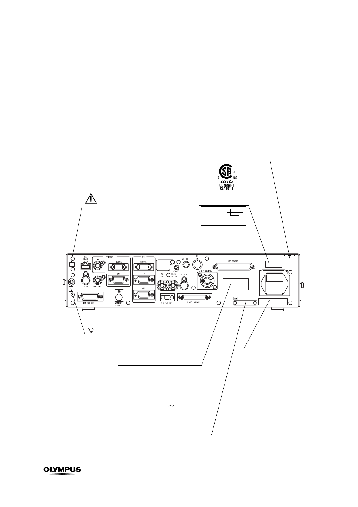
Labels and Symbols
Fuse rating
FUSES
T5AL250V
CSA/UL marking
Caution that only the
exclusive cable can be
connected.
Manufacturer name
Serial number plate
Electric rating
The product name, rated voltage
and frequency are shown.
EVIS EXERA II
VIDEO SYSTEM CENTER
MODEL OLYMPUS CV-180
INPUT 100-240V
50/60Hz 150VA
Potential equalization terminal
Safety-related labels and symbols are attached on the locations shown below. If
labels or symbols are missing or illegible, contact OLYMPUS.
Rear panel
Labels and Symbols
EVIS EXERA II VIDEO SYSTEM CENTER CV-180
1
Page 10

Labels and Symbols
Back cover of this instruction manual
Manufacturer
Authorized representative in the European Community
2
EVIS EXERA II VIDEO SYSTEM CENTER CV-180
Page 11

Important Information — Please Read Before Use
Important Information — Please Read
Before Use
Intended use
This video system center has been designed to be used with OLYMPUS camera
heads, endoscopes, light sources, monitors, endo-therapy accessories and
other ancillary equipment for endoscopic diagnosis, treatment and video
observation. Do not use this video system center for any purpose other than its
intended use.
Instruction manual
This instruction manual contains essential information on using this video
system center safely and effectively. Before use, thoroughly review this manual
and the manuals of all equipment which will be used during the procedure and
use the equipment as instructed.
Keep this and all related instruction manuals in a safe, accessible location. If you
have any questions or comments about any information in this manual, please
contact Olympus.
Terms used in this manual
Light source:
The light source provides light and electrical signals to the endoscope. It
also provides electrical signals to the video system center.
Video printer:
The video printer is a device that prints the frozen video image.
Wall mains outlet:
The wall mains outlet is a wall AC mains power outlet socket having the
exclusive terminal for grounding.
Isolation transformer:
The isolation transformer is a safety device that is used to isolate noninsulated equipment with potentially high leakage currents to decrease the
possibility of electric shock.
Image sensor (CCD):
Image sensor (CCD) is a device that converts light into electrical signals.
EVIS EXERA II VIDEO SYSTEM CENTER CV-180
3
Page 12

Important Information — Please Read Before Use
Automatic brightness control:
The automatic brightness control automatically adjusts the intensity of the
light emitted from the light source so that the endoscopic image will be
maintained at constant brightness even if the distance between the distal
end of the endoscope's insertion tube and the subject changes.
Color adjustment:
Color adjustment adjusts the color balance on the video monitor.
Iris:
The iris function is used to electrically measure the brightness of an
endoscopic image to obtain a control signal for the purpose of automatic
light adjustment.
Freeze:
The freeze function creates a stationary view of the moving image.
Release:
The release function is used to capture and record an endoscopic image.
Edge enhancement:
Edge enhancement is an image processing technique that electronically
sharpens the edges of an image.
Structure enhancement:
Structure enhancement is an image processing technique that
electronically emphasizes the detailed patterns and edges of an image to
increase sharpness.
PinP (Picture in picture):
PinP function displays both the image of the endoscopic live image and
the image of an external device on the monitor simultaneously.
PC card:
A digital medium for storage of images, etc.
Wash out:
Wash out is the inability to see details in the endoscopic image due to
excessive brightness.
HDTV:
High Definition Television. This is a format for high resolution video
transmission featuring higher definition than the standard SDTV format.
4
EVIS EXERA II VIDEO SYSTEM CENTER CV-180
Page 13

SDTV:
Standard Definition Television. It is the format used in standard video
systems.
Special light observation:
This is a observation using filtered light.
NBI (narrow band imaging):
This is one of the special light observations using the narrow band
observation light.
User qualifications
If there is an official standard on user qualifications to perform endoscopy and
endoscopic treatment that is defined by the medical administration or other
official institutions, such as academic societies on endoscopy, follow that
standard. If there is no official qualification standard, the operator of this
instrument must be a physician approved by the medical safety manager of the
hospital or person in charge of the department (department of internal medicine,
etc.).
Important Information — Please Read Before Use
The physician should be capable of safely performing the planned endoscopy
and endoscopic treatment following guidelines set by the academic societies on
endoscopy, etc., and considering the difficulty of endoscopy and endoscopic
treatment. This manual does not explain or discuss endoscopic procedures.
Instrument compatibility
Refer to the “System chart” in the Appendix to confirm that this video system
center is compatible with the ancillary equipment being used. Using incompatible
equipment can result in patient injury or equipment damage and makes it
impossible to obtain the expected functionality.
This instrument complies with the EMC standard for medical electrical
equipment; edition 2 (IEC 60601-1-2: 2001). However, when connecting to an
instrument that complies with the EMC standard for medical electrical
equipment; edition 1 (IEC 60601-1-2: 1993), the whole system complies with
edition 1.
EVIS EXERA II VIDEO SYSTEM CENTER CV-180
5
Page 14

Important Information — Please Read Before Use
Repair and modification
This video system center does not contain any user-serviceable parts. Do not
disassemble, modify or attempt to repair it; patient or operator injury, equipment
damage and/or the impossibility to obtain the expected functionality can result.
Some problems that appear to be malfunctions may be correctable by referring
to Chapter 10, “Troubleshooting”. If the problem cannot be resolved using the
information in Chapter 10, contact Olympus. This instrument is to be repaired by
Olympus technicians only.
Signal words
The following signal words are used throughout this manual:
Indicates an imminently hazardous situation which, if not
avoided, will result in death or serious injury.
Indicates a potentially hazardous situation which, if not
avoided, could result in death or serious injury.
Indicates a potentially hazardous situation which, if not
avoided, may result in minor or moderate injury. It may also
be used to alert against unsafe practices or potential
equipment damage.
Indicates additional helpful information.
6
EVIS EXERA II VIDEO SYSTEM CENTER CV-180
Page 15

Dangers, warnings and cautions
Follow the dangers and cautions given below when handling this video system
center. This information is to be supplemented by the dangers and cautions
given in each chapter.
• Strictly observe the following precautions. Failure to do so
may place the patient and medical personnel in danger of
electric shock.
When this video system center is used to examine a
patient, do not allow metal parts of the endoscope or its
accessories to touch metal parts of other system
components. Such contact may cause unintended current
flow to the patient.
Keep fluids away from all electrical equipment. If fluids are
spilled on or into the unit, stop operation of the video
system center immediately and contact Olympus.
Important Information — Please Read Before Use
Do not prepare, inspect or use this video system center
with wet hands.
• Never install and operate the video system center in
locations where:
the concentration of oxygen is high;
oxidizing agents (such as nitrous oxide (N
in the atmosphere;
flammable gases are present in the atmosphere;
flammable liquids are near.
Otherwise, explosion or fire may result because this video
system center is not explosion-proof.
O)) are present
2
EVIS EXERA II VIDEO SYSTEM CENTER CV-180
7
Page 16

Important Information — Please Read Before Use
• In case of instrument failure or malfunction, always keep
• Never insert anything into the ventilation grills of the video
• Although the illumination light emitted from the endoscope's
another video system center in the room ready for use.
system center. It can cause an electric shock and/or fire.
distal end is required for endoscopic observation and
treatment, it may also cause alteration of living tissues such
as protein denaturation of liver tissue and perforation of the
intestines by inappropriate use.
Observe the following warnings on the illumination.
Always set the minimum required brightness. The
brightness of the image on a video monitor may differ
from the actual brightness at the distal end of an
endoscope. Especially in combination with endoscopes
using an electrical shutter function, pay attention to the
brightness level setting of the light source. When this
instrument is used with a light source compatible with
automatic brightness control function, be sure to use this
function. The automatic brightness control function can
keep the illumination light properly. Refer to the instruction
manual of the light source for details.
Do not continue observation in the proximity to tissue or
keep the distal end of the endoscope in contact with living
tissue for a long time. It may cause patient burns.
When discontinuing the use of the endoscope, be sure to
turn the light source OFF so that the endoscope does not
irradiate unnecessary light.
• This product may interfere with other medical electronic
equipment used in combination with it. Before use, refer to
the Appendix to confirm the compatibility of this instrument
with all equipment to be used.
• Do not use this product in any place where it may be subject
to strong electromagnetic radiation (for example, in the
vicinity of a microwave therapeutic device, MRI, wireless set,
short-wave therapeutic device, cellular/portable phone, etc.).
This may impair the performance of the product.
8
EVIS EXERA II VIDEO SYSTEM CENTER CV-180
Page 17

Important Information — Please Read Before Use
• If the endoscopic image dims during use, blood, mucus or
debris may adhere to the light guide on the distal end of the
endoscope. Carefully withdraw the endoscope from the
patient and remove the blood or mucus in order to obtain
optimum illumination and to ensure the safety of the
examination. If you continue to use the endoscope in such a
condition, the distal end temperature may rise and cause
mucosal burns. It may also cause patient and/or operator
injury.
• Do not rely on the special light observation method alone for
primary detection of lesions or for a decision regarding any
potential diagnostic or therapeutic intervention.
• For reasons described below, do not rely on the NBI imaging
modality alone for primary detection of lesions or to make a
decision regarding any potential diagnostic or therapeutic
intervention.
It has not been demonstrated to increase the yield or
sensitivity of finding any specific mucosal lesion including
colonic polyps or Barrett’s esophagus.
• To display observation images, connect the output terminal
of the video system center directly to the monitor. Do not
make the connection via any ancillary equipment. Images
may disappear during observation depending on the
condition of ancillary equipment.
• Do not use a pointed or hard object to press the buttons on
the front panel and/or keyboard. This may damage the
buttons.
• Do not touch the electrical contacts inside the video system
center's connectors.
• Do not apply excessive force to this video system center
and/or other instruments connected. Otherwise, damage
and/or malfunction can occur.
• Do not connect or disconnect the endoscope connector while
this video system center is turned ON. Connecting or
disconnecting the endoscope while this video system center
is ON may destroy the CCD. Turn the video system center
OFF before connecting or disconnecting the endoscope.
• Clean and vacuum dust the ventilation grills using a vacuum
cleaner, when necessary. Otherwise, the video system
center may break down and gets damaged from overheating.
EVIS EXERA II VIDEO SYSTEM CENTER CV-180
9
Page 18
Important Information — Please Read Before Use
• Be sure that this instrument is not used adjacent to or
• Electromagnetic interference may occur to this instrument
stacked with other equipment (other than the components of
this instrument or system) to avoid electromagnetic
interference.
when it is placed near equipment marked with the following
symbol or other portable and mobile RF communications
equipment such as cellular phones. If radio interference
occurs, mitigation measures may be necessary, such as
reorienting or relocating this instrument or shielding the
location.
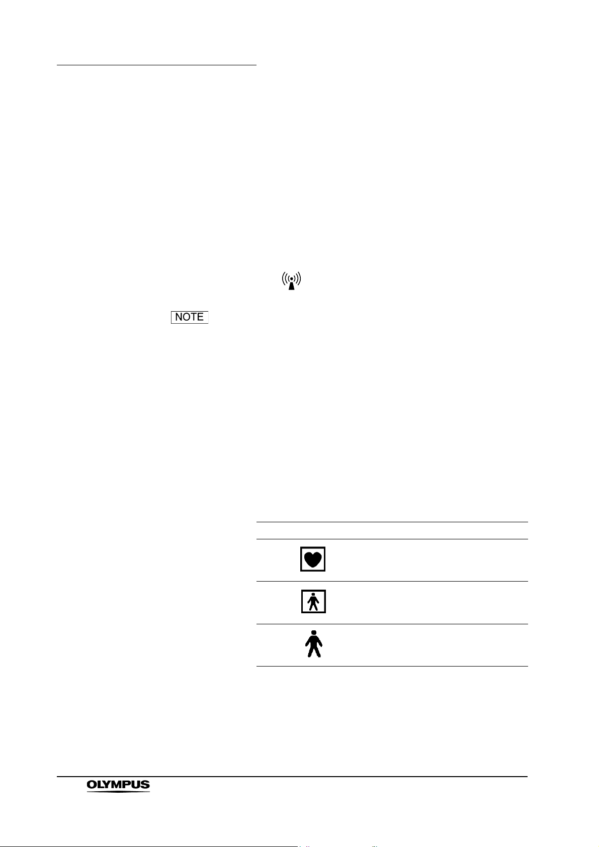
As defined by the international safety standard (IEC 60601-
1), medical electrical equipment is classified into the
following types: TYPE CF applied part (the instrument can
safely be applied to any part of the body, including the heart),
and TYPE B/BF applied part (the instrument can safely be
applied to any organ except the heart). The part of the body
that an endoscope or electrosurgical accessory can safely be
applied to depends on the classification of the equipment to
which the instruments are connected. Before beginning the
procedure, check the current leakage classification type of
each instrument to be used for the procedure. Classification
types are clearly specified in the instruments' instruction
manuals.
10
Symbol Classification
TYPE CF applied part
TYPE BF applied part
TYPE B applied part
EVIS EXERA II VIDEO SYSTEM CENTER CV-180
Page 19

Cardiac applications
Important Information — Please Read Before Use
• Use only the devices listed in the “System chart” in the
Appendix for endoscopic observation or treatment of the
heart or areas near the heart. Other combinations of
equipment may cause ventricular fibrillation or seriously
affect the cardiac function of the patient.
• For cardiac applications, never support the endoscope with a
metal surgical arm which is not electrically isolated from the
ground. If not isolated, the endoscope will be connected to
the ground through the surgical arm and bed, and will
conduct unexpected leakage current which may seriously
affect the cardiac function of the patient.
• The use of medical devices not specifically designed for
cardiac applications may cause ventricular fibrillation or
seriously affect the cardiac function of the patient. As
specified by the international standard IEC 60601-1, any
applied part used for observation or treatment of the heart or
areas near the heart must meet “TYPE CF applied part”
requirements for low electrical leakage current. When using
endoscopes for endoscopic cardiac applications, the applied
part requirements include all devices directly connected to
the endoscope, such as the light guide cable, camera head
and telescope holder. Each of these devices must
individually meet the “TYPE CF applied part” requirements
for leakage current limits if they are to be used for cardiac
applications.
The OLYMPUS light guide cables and camera heads listed in
the “System chart” in the Appendix (TYPE CF applied part)
which are suitable for cardiac applications bear a mark.
EVIS EXERA II VIDEO SYSTEM CENTER CV-180
11
Page 20

Summary of Equipment Functions
Summary of Equipment Functions
This instrument is a system controller of the endoscopic image observation
system that displays, records and prints the endoscopic images. Some of the
functions of this instrument described below are enabled only when the required
equipment are connected to this instrument. For more details, refer to the
instruction manuals for this instrument and the other instruments connected.
Displaying the endoscopic images on the monitor
• The endoscopic live image and the other images of, for example, the
ultrasonic endoscope connected to this instrument can be displayed on
the monitor.
• The endoscopic image and other external images can be displayed on
the same monitor at the same time (PinP function).
“PinP (picture in picture) display” on page 64
• Either a standard-definition (SDTV) monitor or high-definition (HDTV)
monitor can be used.
Special light observation
Endoscopic observation using filtered light is available.
Section 5.8, “Special light observation” on page 151
Adjusting the endoscopic images
Images can be adjusted to enable clear and convenient observation.
• Adjustment of the image color
“Color tone adjustment (“COLOR”)” on page 98
• Adjustment of the image brightness
“Brightness adjustment (Exposure)” on page 71
• Changing the iris mode
“Iris mode” on page 69
• Changing the contrast mode
“Contrast mode (“Shift” + “F6”)” on page 90
12
• Enhancement of edge lines and patterns of the images
“Image enhancement mode (ENH.)” on page 67
• Changing the image size
“Image size (“F8”)” on page 94
EVIS EXERA II VIDEO SYSTEM CENTER CV-180
Page 21

• Enlargement of the images
“Image zooming (“F7”)” on page 91
Entering patient data
• The patient data such as name, sex, etc. can be entered and displayed
on the monitor with the endoscopic live image.
Section 4.6, “Patient data” on page 57 and Section 5.6, “Pre-entry of
patient data” on page 136.)
• Up to 40 sets of patients data can be stored on the PC card. These
patient data can be copied to the other CV-180.
“Recording patient data into PC card” on page 144
Customizing the operations
Up to 20 remote switch settings and other functions such as iris mode, image
enhancement, etc., can be stored.
Section 9.3, “User preset” on page 216
Summary of Equipment Functions
Recording images
• The endoscopic image can be recorded on the PC card.
Section 5.3, “Image recording and playback (PC card)” on page 106
• The endoscopic image can be recorded on the image-recording device
connected to this instrument, and the recorded images can be played
back.
Section 5.4, “Image recording and playback (other than PC card)” on
page 127
• The endoscopic image can be printed from the printer connected to this
instrument.
Section 5.5, “Printing images” on page 131
Operation of ancillary equipment
• Video casette recorder
“Videocassette recorder (VCR)” on page 129
• Video printer
Section 5.5, “Printing images” on page 131
• Image filing system
“Image filing system” on page 127
EVIS EXERA II VIDEO SYSTEM CENTER CV-180
13
Page 22
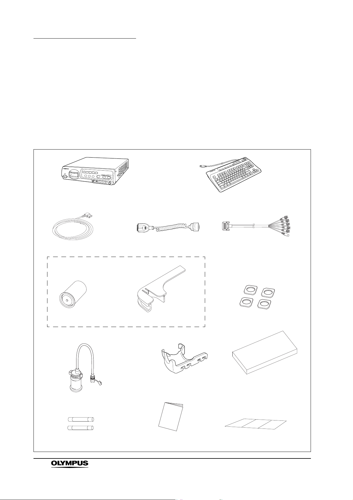
Chapter 1 Checking the Package Contents
White cap holder (MAJ-960)
White cap (MH-155)
Video system center (CV-180)
Keyboard (MAJ-1428)
Videoscope cable EXERA II
(MAJ-1430)
Power cord
HDTV/SDTV monitor cable
(MAJ-1462)
Foot holder (MAJ-1433, 4 pcs.)
Spare fuse (MAJ-1432, 2 pcs.)
Cable color sheet
Scope cable holder (MAJ-1466)
Instruction manual
Water container (MAJ-901)
Keyboard cover
(MAJ-1557)
White cap set (MAJ-941)
Chapter 1 Checking the Package
Contents
Match all items in the package with the components shown below. Inspect each
item for damage. If the instrument is damaged, a component is missing or you
have any questions, do not use the instrument; immediately contact Olympus.
14
EVIS EXERA II VIDEO SYSTEM CENTER CV-180
Page 23
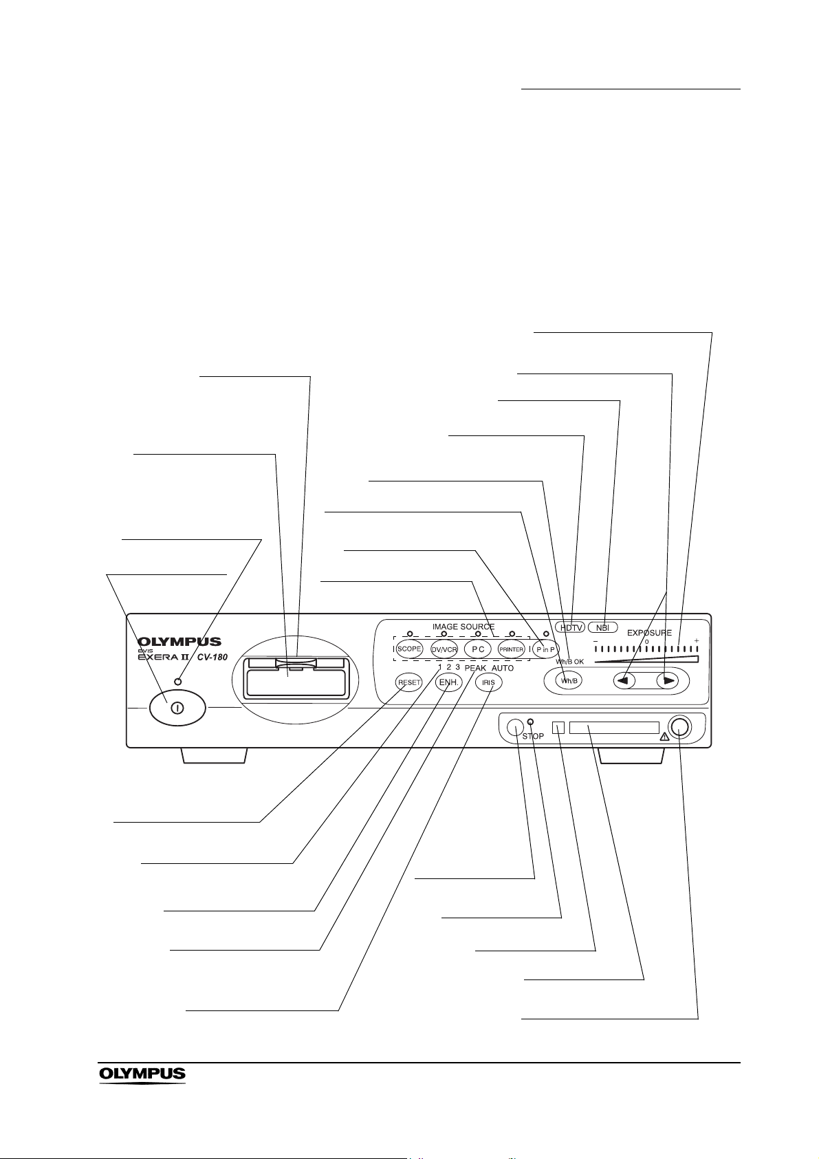
Chapter 2 Nomenclature and Functions
4. Locking lever
3. Video connector
socket
2. Power indicator
1. Power switch
5. Image source buttons
7. White balance (Wh/B) button
9. HDTV indicator
12. Exposure level
(EXPOSURE) indicator
11. Exposure adjustment
(EXPOSURE) buttons
10. NBI indicator
22. RESET button
21. Image enhancement
mode indicators
20. Image enhancement
mode (ENH.) button
19. Iris mode indicators
18. Iris mode (IRIS)
button
17. STOP button
16. PC card status
indicator
15. Eject button
14. PC card slot
13. PinP composite terminal
6. Picture in picture
(PinP) button
8. White balance (Wh/B OK)
indicator
Chapter 2 Nomenclature and Functions
2.1 Front panel
EVIS EXERA II VIDEO SYSTEM CENTER CV-180
15
Page 24

Chapter 2 Nomenclature and Functions
1. Power switch
Press to turn the video system center ON or OFF.
2. Power indicator
Lights up when the video system center is ON.
3. Video connector socket
The video plug of the videoscope cable, videoscope or camera head are
connected to this socket.
4. Locking lever
Press down to disconnect the video plug of the videoscope cable,
videoscope or camera head.
5. Image source buttons
Press these buttons to select the image sources to be displayed on the
monitor. Press and hold the buttons to change (except “SCOPE”).
“Image source buttons” on page 62
Button The image on the monitor
SCOPE The endoscopic live image
DV/VCR The image of the videocassette recorder, etc.
PC The image of the image filing system
PRINTER The image of the video printer
6. Picture in picture (PinP) button
Press to display an image of the connected ancillary equipment and the
endoscopic live image together on the monitor.
• Setting of the PinP function
“PinP (picture in picture) function” on page 246
• Operation of the PinP function
“PinP (picture in picture) display” on page 64
7. White balance (Wh/B) button
Press to perform the white balance adjustment.
Section 4.5, “White balance adjustment” on page 52
8. White balance (Wh/B OK) indicator
The indicator lights up when the white balance adjustment is completed.
9. HDTV indicator
Lights up green when the instrument is turned ON, and turns white when the
HDTV compatible endoscope is connected to this instrument.
16
10. NBI indicator
Lights up green when the NBI compatible endoscope is connected to this
instrument, and turns white during NBI observation. This indicator works
only when the light source CLV-180 is used.
“NBI (narrow band imaging)” on page 151
EVIS EXERA II VIDEO SYSTEM CENTER CV-180
Page 25

Chapter 2 Nomenclature and Functions
11. Exposure adjustment (EXPOSURE) buttons
Press to adjust the brightness of the observation light. When CLV-180 is
used, this button is interlocked with the “BRIGHTNESS” on CLV-180.
“Brightness adjustment (Exposure)” on page 71
12. Exposure level (EXPOSURE) indicator
Indicates the brightness level of the observation light.
“Brightness adjustment (Exposure)” on page 71
13. PinP composite terminal
The ultrasound center (EUS), endoscope position detecting unit (UPD) etc.
can be connected to this connector to input the images to be displayed
together with the endoscopic observation image. The PinP function can also
be used with the PinP Y/C terminal on the rear panel. However, the PinP
composite terminal takes priority over the PinP Y/C terminal.
14. PC card slot
Insert the PC card adapter (optional) in this slot. The xD picture card can be
used as the storage media.
“PC card slot and eject button” on page 76
15. Eject button
Press to remove the PC card from the PC card slot.
“PC card slot and eject button” on page 76
16. PC card status indicator
This indicator lights up green when the PC card is inserted into the PC card
slot, and blinks orange while accessing the PC card.
“PC card slot and eject button” on page 76
17. STOP button
Press to stop accessing the PC card. Be sure to press this button before
removing the PC card from the PC card slot.
“PC card slot and eject button” on page 76
18. Iris mode (IRIS) button
Press to switch the iris mode (brightness adjustment method) of the
endoscopic image. Either “AUTO” or “PEAK” mode can be selected.
•Presetting
“Iris” on page 232
• Switching operation
“Iris mode” on page 69
19. Iris mode indicators
Indicates the iris mode being selected.
EVIS EXERA II VIDEO SYSTEM CENTER CV-180
17
Page 26

Chapter 2 Nomenclature and Functions
20. Image enhancement mode (ENH.) button
“Image enhancement” refers to facilitate observation of edges and patterns
of the endoscopic image by electronic treatment. Press this button to
change the modes of the enhancement methods.
21. Image enhancement mode indicators
One of these indicators light up and indicates the image enhancement mode
being selected. The indicator goes off when the image enhancement is not
used.
22. RESET button
Press and hold the switch to return the settings changed during operation to
the default settings.
“RESET button” on page 80
• Presetting
“Image enhancement (normal observation)” on page 226
or “Image enhancement (NBI observation)” on page 250
• Operation
“Image enhancement mode (ENH.)” on page 67
18
EVIS EXERA II VIDEO SYSTEM CENTER CV-180
Page 27
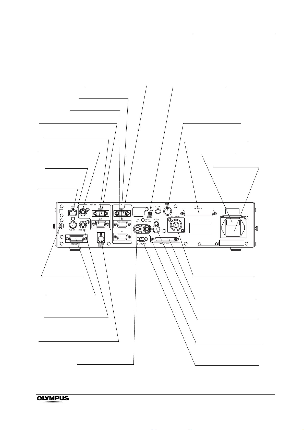
2.2 Rear panel
8. PC remote terminal
12. Fuse box
10. Foot switch terminal
9. Remote terminal
13. AC power inlet
7. PC IN terminal
6. PC OUT terminal
5. Printer remote terminal
4. Printer OUT terminal
3. Printer IN terminal
2. Y/C OUT
terminal
1. Keyboard
terminal
23. Potential
equalization
terminal
22. Monitor OUT
terminal
21. Composite OUT
terminal
20. Monitor remote terminal
19. PC OUT2 terminal
14. Light control terminal
15. Light source terminal
16. PinP Y/C terminal
17. HD/SD SDI OUT terminal
18. Digital OUT terminal
11. VCR remote terminal
Chapter 2 Nomenclature and Functions
EVIS EXERA II VIDEO SYSTEM CENTER CV-180
19
Page 28

Chapter 2 Nomenclature and Functions
1. Keyboard terminal
Connect the keyboard.
2. Y/C OUT terminal
Outputs a Y/C video signals.
3. Printer IN terminal
Connect the video printer. Inputs the analog video signal from the video
printer.
4. Printer OUT terminal
Connect the video printer. Outputs the analog video signal to the video
printer.
5. Printer remote terminal
Connect the video printer. Establishes communication with the video printer.
6. PC OUT terminal
Connect the image filing system. Outputs the analog video signal to the
image filing system.
7. PC IN terminal
Connect the image filing system. Inputs the analog video signal from the
image filing system.
8. PC remote terminal
Connect the image filing system. Establishes communication with the image
filing system.
9. Remote terminal
Outputs the signal synchronizing the release and VCR (Rec/Pause)
operation.
10. Foot switch terminal
Connect the foot switch.
11. VCR remote terminal
Connect an Olympus-recommended VCR. Outputs the analog video signal
and the remote signals to the VCR.
12. Fuse box
Stores the fuses that protect the instrument from electrical surges.
13. AC power inlet
Connect the provided power cord to supply the AC power via this inlet.
14. Light control terminal
Connect a light source that supports the analog interface.
20
15. Light source terminal
Connect a light source CLV-180 that supports the digital interface.
EVIS EXERA II VIDEO SYSTEM CENTER CV-180
Page 29

Chapter 2 Nomenclature and Functions
16. PinP Y/C terminal
The ultrasound center (EUS), endoscope position detecting unit (UPD) etc.
can be connected to this connector to input the image to be displayed
together with the endoscopic observation image. The PinP function can also
be used with the PinP composite terminal on the front panel. However, the
PinP composite terminal takes priority over the PinP Y/C terminal.
17. HD/SD SDI OUT terminal
Connect a monitor compatible with the serial digital interface (SDI). Outputs
the SDI signal.
18. Digital OUT terminal
Connect an Olympus-recommended digital video recorder to output and
input the digital video signal to the digital video recorder, using IEEE1394
cable.
19. PC OUT2 terminal
Connect the image filing system. Outputs an SDI signal to the image filing
system.
20. Monitor remote terminal
Connect the monitor. Outputs the monitor control signal to the monitor.
21. Composite OUT terminal
Outputs the composite video signal.
22. Monitor OUT terminal
Connect the monitor. Outputs analog video signals to the monitor. HDTV
signal is output when the HDTV compatible endoscope is connected. This
connector can output a 180 rotated image (see “Monitor orientation
function” on page 245).
23. Potential equalization terminal
This terminal is connected to a potential equalization terminal of the other
equipment connected to this instrument. The electric potential of their
equipment are made equal.
EVIS EXERA II VIDEO SYSTEM CENTER CV-180
21
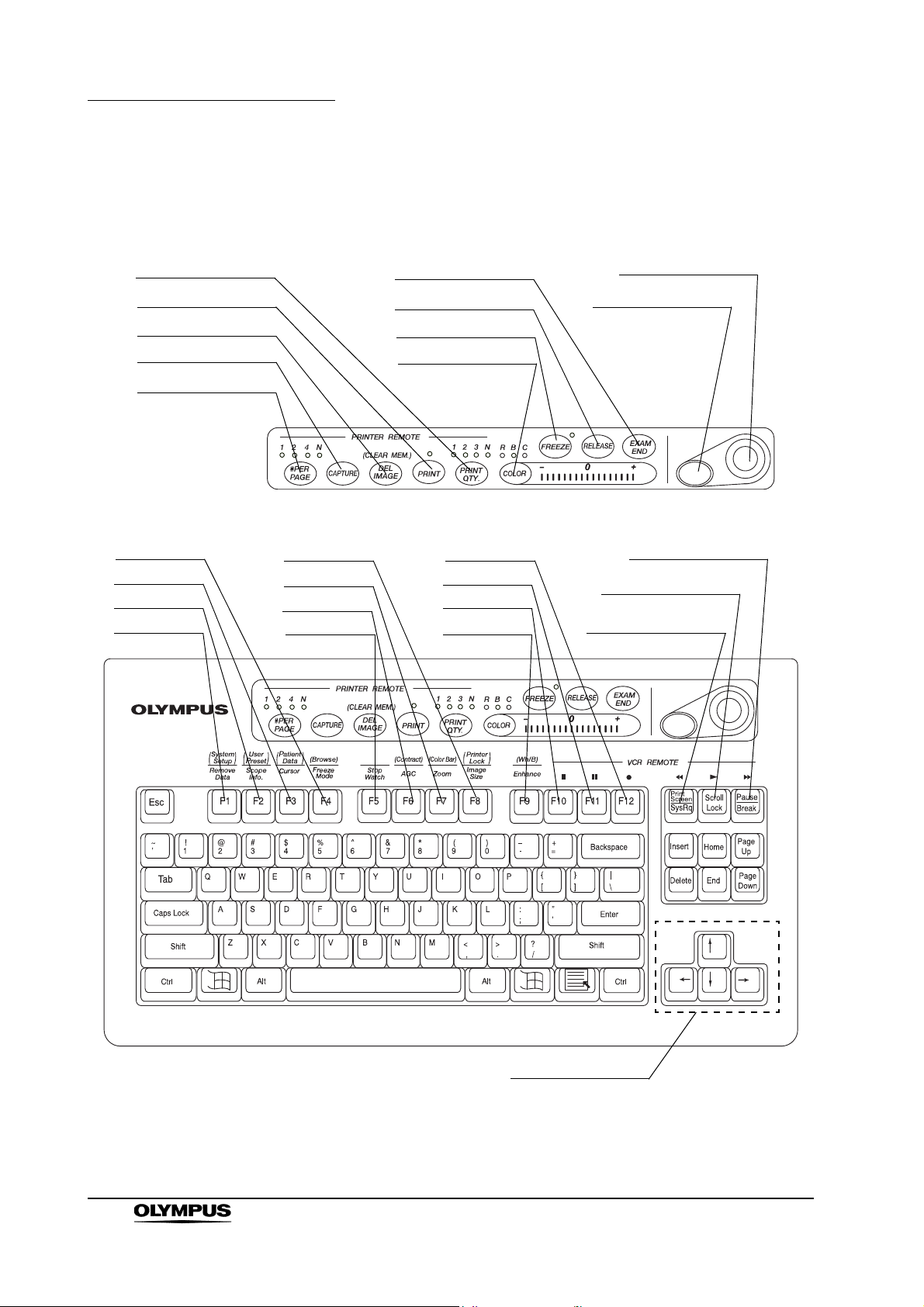
Page 30
Chapter 2 Nomenclature and Functions
20. PRINT QTY. key
19. PRINT key
18. DEL IMAGE key
17. CAPTURE key
24. EXAM END key
23. RELEASE key
22. FREEZE key
21. COLOR key
26. Domepoint
25. Click key
4. F4 key
3. F3 key
2. F2 key
1. F1 key
8. F8 key
7. F7 key
6. F6 key
5. F5 key
12. F12 key
11. F11 key
10. F10 key
9. F9 key
16. #PER PAGE key
15. Pause key
14. Scroll lock key
13. Print screen key
27. Arrow keys
2.3 Keyboard
22
EVIS EXERA II VIDEO SYSTEM CENTER CV-180
Page 31

Chapter 2 Nomenclature and Functions
1. F1 key
Press to clear or re-display the patient data on the monitor step by step.
“Clearing characters from the screen (“F1”)” on page 82
Press together with the “Shift” key to display the system setup menu to set
the basic functions of this instrument.
“System setup (“Shift” + “F1”)” on page 84
2. F2 key
Press to display the scope information window when using an endoscope
with the endoscope information memory function. While the window is still
open, press this key again to display the scope information menu that shows
the information about the connected endoscope.
“Scope information (“F2”)” on page 84
Press together with the “Shift” key to display the user preset menu to set
and call up the observation condition of the endoscopic image.
See “User preset (“Shift” + “F2”)” on page 85
3. F3 key
Press to switch the display of the cursor on screen ON and OFF.
“Cursor (“F3”)” on page 85
Press together with the “Shift” key to display the patient data menu to enter
or call up the patient data onto the monitor.
“Patient data (“Shift” + F3)” on page 86
4. F4 key
Press to change the freeze mode.
“Freeze mode (“F4”)” on page 86
Press together with the “Shift” key to display the PC card menu to store or
call up the image data or the patient data from the PC card.
“Browse (“Shift” + “F4”)” on page 87
5. F5 key
Press to change the clock on the monitor to a stopwatch, and to start time
counting.
“Stopwatch (“F5”)” on page 88
6. F6 key
Press to switch the auto gain control (AGC) function ON and OFF.
“Automatic gain control (AGC) (“F6”)” on page 89
Press together with the “Shift” key to switch between the three steps of the
observation image contrast.
“Contrast mode (“Shift” + “F6”)” on page 90
7. F7 key
Press to change the zoom ratio of the observation image in three steps (x1;
x1.2; x1.5).
“Image zooming (“F7”)” on page 91
Press together with the “Shift” key to display the color bar for checking the
color of the monitor.
“Color bar (“Shift” + “F7”)” on page 93
EVIS EXERA II VIDEO SYSTEM CENTER CV-180
23
Page 32

Chapter 2 Nomenclature and Functions
8. F8 key
Press to change the image area size on the monitor.
“Image size (“F8”)” on page 94
Press together with the “Shift” key to disable the functions of the following 5
keys for video printer operation: #PER Page, CAPTURE, DEL IMAGE,
PRINT, PRINT QTY.
“Printer lock (“Shift” + “F8”)” on page 95
9. F9 key
Press to switch the image enhancement mode.
“Image enhancement (“F9”)” on page 96
Press together with the “Shift” key to perform the white balance adjustment.
“White balance adjustment (“Shift” + “F9”)” on page 97
10. F10 key
Press to stop ( ) the VCR.
“Videocassette recorder (VCR)” on page 129
11. F11 key
Press to pause ( ) the VCR. Press the Scroll ( ) key to resume play.
“Videocassette recorder (VCR)” on page 129
12. F12 key
Press to start ( ) VCR recording.
“Videocassette recorder (VCR)” on page 129
13. Print screen key
Press to fast-rewind ( ) the VCR.
“Videocassette recorder (VCR)” on page 129
14. Scroll lock key
Press to playback ( ) the VCR.
“Videocassette recorder (VCR)” on page 129
15. Pause key
Press to fast-forward ( ) the VCR.
“Videocassette recorder (VCR)” on page 129
16. #PER PAGE key
Press to set the number of images per video print sheet. The indicator
corresponding to the number lights up. An arbitrary number “N” on the
keyboard depends on the printer.
Section5.5, “Printing images” on page 131
17. CAPTURE key
Press to capture the image in the video printer.
Section5.5, “Printing images” on page 131
24
EVIS EXERA II VIDEO SYSTEM CENTER CV-180
Page 33

Chapter 2 Nomenclature and Functions
18. DEL IMAGE key
Press to set the printer cursor back on the print sheet by one. Press together
with the “Shift” key to delete a captured image at the position of the cursor.
Section5.5, “Printing images” on page 131
19. PRINT key
Press to print the images captured in the video printer.
Section5.5, “Printing images” on page 131
20. PRINT QTY. key
Press to specify the number of video print sheets to print simultaneously.
The indicator corresponding to the number lights up. An arbitrary number
“N” on the keyboard can be specified in the system setup menu.
Section5.5, “Printing images” on page 131
21. COLOR key
Press to select R (Red), B (Blue) or C (Chroma) to adjust the color of the
endoscopic image. The lamp corresponding to the selected tone above the
key lights up. Adjust the selected color tone using the “right” or “left” arrow
keys. The indicator on the right side of the “COLOR” key shows the
adjustment status.
“Color tone adjustment (“COLOR”)” on page 98
22. FREEZE key
Press to freeze the live endoscopic image. Press the key again to return to
the live image.
“Freeze (“FREEZE”)” on page 99
23. RELEASE key
Press to record the image into the video printer, image filing system and PC
card. The recording devices to operate should be set in advance.
“Release (“RELEASE”)” on page 101
24. EXAM END key
Press to execute the examination end processing.
“Ending examination (“EXAM END”)” on page 105
25. Click key
Press this key to enter an item after selecting the item using the domepoint.
“Domepoint” on page 81
26. Domepoint
Moves the arrow pointer. Selects an item in the menu or puts a marking in
the endoscopic image.
“Domepoint” on page 81
EVIS EXERA II VIDEO SYSTEM CENTER CV-180
25
Page 34

Chapter 2 Nomenclature and Functions
27. Arrow keys
Moves the cursor.
Press one of these keys together with the “Shift” key to display the arrow
pointer on the endoscopic image.
“Arrow pointer (“Shift” + arrow keys and domepoint)” on page 102
28. Other keyboard keys
•Esc
Cancels the selection or returns to the previous screen.
•Tab
Goes to the next input area, or returns to the previous input area.
• Enter
Fixes entry and goes to the next text box or screen.
• Shift, Alt
Executes functions together with other keys.
• Back space
Clears the character left of the cursor.
•Delete
Clears the character right of the cursor.
26
EVIS EXERA II VIDEO SYSTEM CENTER CV-180
Page 35

Chapter 2 Nomenclature and Functions
Front side
Rear side
Ventilation grills
Ventilation grills
Scope side connector
Connect to the scope
connector of the endoscope.
“UP” mark
Video plug
Connect to the video
system center “UP”
side up.
Connect to the video
connector socket of the
video system center.
2.4 Side panels
2.5 Videoscope cable EXERA II (MAJ-1430)
EVIS EXERA II VIDEO SYSTEM CENTER CV-180
27
Page 36

Chapter 2 Nomenclature and Functions
2.6 Set-up of screen options
The software of this instrument has the following functions.
• The screen of the endoscopic live image and the images of the external
instruments connected to this instrument
This is the basic screen of the instrument. This instrument starts the
endoscopic live image when it is turned ON.
Section 3.4, “Inspection of the monitor display” on page 38
• System setup screen
This screen is used for setting the basic functions to operate this instrument
and the other instruments connected to it correctly.
Section 9.2, “System setup” on page 194
• User preset screen
Up to 20 user presets are available to save individual user settings. The
factory default settings are set before shipment.
Section 9.3, “User preset” on page 216
• Patient data screen
Patient name, sex, age, etc. can be entered for up to 40 patients in advance.
Existing patient data can be accessed and displayed on the monitor together
with the endoscopic image, and can be stored on the PC card.
Section 5.6, “Pre-entry of patient data” on page 136
• PC card menu screen
This screen is used to browse endoscopic images on the PC card.
“PC card menu” on page 110
• Scope information screen
This screen is used to display and/or enter endoscope information such as
the type of endoscope, etc.
Section 5.7, “Scope information” on page 148
• Color bar screen
This screen is used to check the display color.
“Color bar (“Shift” + “F7”)” on page 93
28
EVIS EXERA II VIDEO SYSTEM CENTER CV-180
Page 37

2.7 Monitor
1. Patient data
2. System clock
3. Image recording device display
4. Image information
5. Flushing pump
6. PC card capacity
7. Index image
8. Attending physician
10. Special light
observation display
11. Endoscopic image
12. Arrow pointer
14. Scope nickname
9. Comments
13. Orientation
ABC123
Mike Johnson
M 51
03/03/1954
12/12/2005
12:12:12
CVP: A4/4
D.F: 99
VCR
Ct: N Eh: A8
Z: x1.5
Pump
Media:
John Smith
Cardiac end of the stomach
R
V
NBI
Endoscopic image display
Chapter 2 Nomenclature and Functions
1. Patient data
Patient data such as name sex, etc. can be entered and displayed in this
area.
Section 4.6, “Patient data” on page 57
2. System clock
Date and time are displayed. The date format can be set.
“Date and time” on page 197
The clock has the stopwatch function.
“Stopwatch (“F5”)” on page 88
3. Image recording device display
The status of the image recording devices that record and print the image
are displayed only when the recording devices are activated.
Indication Device Details
CVP Video printer page 131
D.F Digital filing system page 127
VCR Videocassette recorder page 129
EVIS EXERA II VIDEO SYSTEM CENTER CV-180
29
Page 38

Chapter 2 Nomenclature and Functions
4. Image information
Displays image information on the monitor. The indications are displayed
only when these function are operated.
Indication Meaning Details
Ct Contrast page 90
Eh Enhancement mode page 67
Z Zoom ratio page 91
5. Flushing pump
Displayed only when the Olympus flushing pump (OFP) is processing.
6. PC card capacity
Indicates the remaining memory level of the PC card when the PC card is
inserted in the PC card slot.
“Storage level of the PC card” on page 106
7. Index image
Displays the reference image of the image taken by “RELEASE”.
“Release index time” on page 243
8. Attending physician
The physician’s name can be entered and displayed together with the
patient data.
9. Comments
Comments can be entered and displayed together with the patient data.
10. Special light observation display
Indicates the name of the special observation function during the
observation.
Section 5.8, “Special light observation” on page 151
11. Endoscopic image
The live endoscopic image is displayed in this area. The size and shape of
the image depends on the type of endoscope used.
“Image size” on page 229
12. Arrow pointer
The arrow pointer is used for pointing out a part of the endoscopic image
and for entering data in the menus.
• Displaying
“Arrow pointer (“Shift” + arrow keys and domepoint)” on
page 102
30
• Operation
“Domepoint” on page 81
13. Orientation
“R” mark appears when a 180 reverse image is displayed.
“Monitor orientation function” on page 245
EVIS EXERA II VIDEO SYSTEM CENTER CV-180
Page 39

Chapter 2 Nomenclature and Functions
14. Scope nickname
The scope nickname is displayed when an endoscope with a scope
nickname function is connected.
“Scope nickname” on page 242
EVIS EXERA II VIDEO SYSTEM CENTER CV-180
31
Page 40

Chapter 2 Nomenclature and Functions
CLV
CLV-S
CLE
Function button
Menu name
Text box
Cursor
Arrow pointer
List box
Pull down menu
Scroll bar
Highlight
Saves data, terminates the
menu, etc.
For entering and displaying
data.
Used for entering data.
Moves the cursor, selects the
function buttons, displays the
pull down menus.
Opens the pull down menu
and selects the setting values.
Click “ ” to show the setting
values in the pull down menu.
Shows all setting values not
being displayed in the list box.
Indicates in blue that the
function button is selected.
Data input menu
32
EVIS EXERA II VIDEO SYSTEM CENTER CV-180
Page 41

Chapter 2 Nomenclature and Functions
2.8 Pointer
Highlight, cursor and arrow pointer are available as pointing devices for the
endoscopic image and menus on the monitor.
Pointer Function Screen Displaying and operation
Highlight Indicates the button
selected.
• System setup menu
• User preset menu
• Patient data menu
• Scope information menu
• PC card information
menu
Always displayed.
Movable by pressing the arrow, “Tab”,
or “Shift” + “Tab” keys.
Cursor Indicates the position to
enter data.
Arrow pointer Moves the cursor and
focus or points out a
specific portion of the
image.
• System setup menu
• User preset menu
• Patient data menu
• Scope information menu
• PC card information
menu
• Endoscopic image
screen
• System setup menu
• User preset menu
• Patient data menu
• Scope information menu
• PC card menu Always displayed on image screen
• Endoscopic image
screen
Always displayed.
Movable by pressing the arrow,
“Home”, or “End” keys.
Always displayed.
Movable by the domepoint.
(unless full image screen selected).
Press “Shift” and any arrow key in the
full image screen to display/remove the
arrow pointer.
Press “Shift” and any arrow key.
EVIS EXERA II VIDEO SYSTEM CENTER CV-180
33
Page 42

Chapter 3 Inspection
Chapter 3 Inspection
• Review Chapter 8, “Installation and Connection” thoroughly,
and prepare the instruments properly before inspection. If the
equipment is not properly prepared before each use,
equipment damage, patient and operator injury and/or fire
can occur.
• Before each procedure, inspect the video system center as
instructed below. Inspect other equipment to be used with
this video system center as instructed in their respective
instruction manuals. Should any irregularity be observed, do
not use the video system center and see Chapter 10,
“Troubleshooting”. If the irregularity is still observed after
consulting Chapter 10, contact Olympus. Damage or
irregularity may compromise patient or user safety and may
result in more severe equipment damage.
Prepare the video system center and other ancillary equipment before each
particular case. Refer to the respective instruction manual for each piece of
equipment.
34
EVIS EXERA II VIDEO SYSTEM CENTER CV-180
Page 43

3.1 Inspection of the power supply
Video connector socket
Power indicator
Power switch
1. Confirm that the videoscope cable, camera head and/or endoscope is
connected to the videoscope cable socket of the instrument.
For the connection of the endoscope or scope cable, refer to
Section 4.2, “Connection of an endoscope” on page 46.
2. Press the power switch of the instrument (see Figure 3.1). The indicator
lamp above the power switch lights up.
Chapter 3 Inspection
Figure 3.1
If the power fails to come ON
When the power fails to come ON, turn the video system center OFF. Then
check the video system center referring to Chapter 10, “Troubleshooting”. If the
power still fails to come ON, contact Olympus.
EVIS EXERA II VIDEO SYSTEM CENTER CV-180
35
Page 44

Chapter 3 Inspection
Examination light
Endoscope’s distal end
3.2 Inspection of the examination light
Do not stare directly into the light beam. This may result in
eye injury.
Turn ON the light source and confirm that examination light is emitted from the
distal end of the endoscope (see Figure 3.2). For operation of the light source,
refer to its instruction manual.
Figure 3.2
36
EVIS EXERA II VIDEO SYSTEM CENTER CV-180
Page 45

Chapter 3 Inspection
3.3 Inspection of the automatic brightness control function
1. Confirm that this instrument is connected to the light source using the light
source cable or light control cable (see Section 8.4, “Light source” on
page 164).
2. According to the directions given in the light source's instruction manual,
confirm that the light source's brightness control is set to “AUTO” and that
the brightness level is in the center of the adjustable range.
3. Move the distal end of the endoscope between 1 and 3 cm from your palm.
Confirm that the brightness of the image on the monitor remains constant.
Confirm that the light emitted from the distal end of the endoscope changes
in your palm.
4. Hold the distal end of the endoscope 3 cm from your palm. Use a piece of
gauze, etc. to prevent the endoscope's distal end and your palm from being
exposed to extraneous light. View the image on the monitor.
5. Confirm that the brightness of the image on the monitor changes when the
light source's brightness level is changed.
• In combination with some endoscope models, the space
between the distal end of the endoscope and your palm in
which the automatic brightness control function is available
will be smaller than 1 - 3 cm. Please refer to the instruction
manual of the endoscope used.
• Depending on the light source connected, the exposure level
indicator on the video system center goes off. Control the
brightness on the light source referring to “Brightness
adjustment (Exposure)” on page 71.
EVIS EXERA II VIDEO SYSTEM CENTER CV-180
37
Page 46

Chapter 3 Inspection
ID:
Name:
Sex: Age:
D.O.B.
12/12/2005
12:12:12
CVP: A4/4
D.F: 99
VCR
Ct: N Eh: A8
Z: x1.5
Pump
Media:
Physician:
Comment:
3.4 Inspection of the monitor display
Be sure to perform white balance adjustment before
inspecting the color on the monitor display. See Section 4.5,
“White balance adjustment” on page 52.
1. Turn the instrument ON. Then the endoscopic image appears on the screen
(see Figure 3.3).
Figure 3.3
2. Confirm that the endoscopic image is normal by observing any object such
as the palm of your hand.
3. Confirm that the date and time are correct.
4. Confirm that the “CVP” counter and “D.F” counter are displayed on the
screen when the video printer and digital filing system are connected.
5. Confirm that enough space is available on the PC card to store endoscopic
images.
• The display layout is variable according to the connected
endoscope and user preset.
• For setting the date or time, refer to “Date and time” on
page 197.
38
EVIS EXERA II VIDEO SYSTEM CENTER CV-180
Page 47

3.5 Inspection of the freeze function
Do not use this instrument when the live image cannot be
observed. Otherwise, patient injury may occur.
1. Press the “FREEZE” key on the keyboard, and confirm that the live
endoscopic image freezes and a short beep is heard.
2. Press the “FREEZE” key again and confirm that the frozen image returns to
the live image.
3. Confirm the function of the scope switches and/or foot switches, when the
freeze function is assigned to these switches.
3.6 Inspection of the release function
Chapter 3 Inspection
1. Press the “RELEASE” key on the keyboard.
2. Confirm that the live image freezes for a short time and a beep is heard.
3. Confirm that the selected recording device is activated.
4. Confirm that the counter for the recording devices, which are displayed on
the monitor, increments by one.
5. Confirm the function of the scope switches and/or foot switches, when the
release function is assigned to these switches.
3.7 Inspection of the PinP (picture in picture) function
According to the “PinP (picture in picture) display” on page 64, confirm that the
PinP indication can be performed correctly.
3.8 Inspection of the orientation function
If the orientation function is activated, confirm that the indication on the monitor
is an endoscopic image rotated by 180 (refer to “Monitor orientation function” on
page 245).
EVIS EXERA II VIDEO SYSTEM CENTER CV-180
39
Page 48

Chapter 3 Inspection
3.9 Inspection of the special light observation function
According to Section 5.8, “Special light observation” on page 151, confirm that
the image of the special light observation can be displayed correctly.
3.10 Inspection of the scope switches and foot switches
If any function is assigned to the scope's remote switches and/or foot switches,
confirm the proper function of these switches.
3.11 Power OFF
Press the power switch of the instrument (see Figure 3.1) to turn the instrument
OFF. The indicator above the switch goes off.
40
EVIS EXERA II VIDEO SYSTEM CENTER CV-180
Page 49

Chapter 4 Operation
This chapter explains the work flow of endoscopic observation using the video
system center. For information on how to use the functions that are not
explained in this chapter, refer to the reference pages.
The operator of the video system center must be a physician or medical
personnel under the supervision of a physician and must have received sufficient
training in clinical endoscopic techniques. This manual, therefore, does not
explain or discuss clinical endoscopic procedures. It only describes basic
operation and precautions related to the operation of the video system center.
• Be sure to wear protective equipment such as eye wear, face
mask, moisture-resistant clothing and chemical-resistant
gloves that fit properly and are long enough so that your skin
is not exposed. Otherwise, dangerous chemicals and/or
potentially infectious material such as blood and/or mucus of
the patient may cause an infection.
Chapter 4 Operation
• Should any irregularity is observed, do not use the video
system center. Damage or irregularity may compromise
patient or user safety and may result in more severe
equipment damage.
• Anytime you observe an abnormality in a video system
center function, stop the examination immediately and take
action according to the following procedures. Using a
defective video system center may cause patient and/or
operator injury.
If the endoscopic image disappears or if the image
freezes and cannot be restored, press the “RESET”
button or temporarily turn the video system center OFF
and wait for about 10 seconds. Then turn it back ON
again.
For ancillary equipment used in conjunction with the video
system center, also turn the power OFF and then ON
again as directed in their respective instruction manuals. If
this fails to correct the problem, immediately stop using
the equipment and turn the video system center and light
source OFF. Then, gently withdraw the endoscope from
the patient as described in the endoscope's instruction
manual.
EVIS EXERA II VIDEO SYSTEM CENTER CV-180
41
Page 50

Chapter 4 Operation
If any other abnormality occurs or is suspected,
immediately stop using the equipment, turn OFF all
equipment, and gently withdraw the endoscope from the
patient as described in the endoscope's instruction
manual. Then refer to the instructions in Chapter 10,
“Troubleshooting”. If the problems cannot be resolved by
the remedial action described in Chapter 10, do not use
the equipment and contact Olympus.
• Combination with other equipment
Do not use the video system center in locations exposed
to direct strong electromagnetic radiations (for example,
microwave treatment device, short wave treatment
device, MRI or radio equipment). Electromagnetic
radiation can interfere with the monitor display.
Use only Olympus high-frequency electrosurgical
equipment with this unit. Non-Olympus equipment can
cause interference on the monitor display or a loss of the
endoscopic image.
Before using high-frequency electrosurgical equipment,
be sure to install and connect the equipment according to
it’s instruction manual and make sure that the noise does
not affect the observation and surgical procedures. If
high-frequency electrosurgical equipment is used without
such confirmation, patient injury may result.
• To activate the auto brightness control function of the light
source, the video system center should be turned ON. If it is
not turned ON, the auto brightness control function is not
activated and the light intensity is set to maximum. In this
case, the endoscope distal end would become hot and could
cause burns to the operator and physician (if a light source
model other than CLV-180 is used).
• When using spray-type medical agents such as lubricant,
anesthetic, or alcohol, use them away from the video system
center so that the medical agents do not contact the video
system center. Medical agents might enter the video system
center through the ventilation grills and may cause
equipment damage.
42
• Do not use a humidifier near the video system center as dew
condensation possibly might occur and it may cause
equipment failure.
EVIS EXERA II VIDEO SYSTEM CENTER CV-180
Page 51

Chapter 4 Operation
• High-frequency electrosurgical equipment can cause slight
interference on the monitor display.
• Sometimes horizontal line noise appears when a slim
endoscope is used. To reduce the horizontal line noise,
select “Edge enhancement” for the enhancement setting.
EVIS EXERA II VIDEO SYSTEM CENTER CV-180
43
Page 52

Chapter 4 Operation
4.1 Operation flow
Please see the operation work flow in Figure 4.1 below. Follow each step of the
work flow for using the video system center.
1. Connect the endoscope to the video system center and the light source.
Section 4.2, “Connection of an endoscope” on page 46
2. Inspect the instruments before use.
Chapter 3, “Inspection” on page 34
3. Turns the instrument ON.
Section 4.3, “Turning the video system center ON” on page 50
4. Select a user name.
Section 4.4, “Recall of user preset data” on page 51
This operation can be skipped when using the user name of the last examination.
5. Adjust the white balance.
Section 4.5, “White balance adjustment” on page 52
When you are planning to use the NBI observation, perform the white balance adjustment for NBI
after performing the white balance for normal-light observation.
6. Enter the patient data.
Section 4.6, “Patient data” on page 57
It is possible to enter the patient data before the examination (see “Entering new patient data” on
page 137).
44
continued on next page
EVIS EXERA II VIDEO SYSTEM CENTER CV-180
Page 53

7. Perform examination.
Chapter 5, “Functions” on page 62
Changes iris mode,
Image enhancement,
Freezes image,
Zooms image,
Recording and printing of the images,
NBI observations, etc.
8. Terminate the examination.
Section 4.9, “Termination of the operation” on page 60
Press “EXAM END” key after the examination. Then turn the CV-180 and other instruments OFF.
Chapter 4 Operation
9. Disconnect the endoscope from the video system center and the light source.
Section 4.9, “Termination of the operation” on page 60
10. Inspect the instruments after use.
Chapter 7, “Care, Storage and Disposal” on page 155
For details on endoscope and light source, see the respective instruction manuals.
11. Reprocess and store the instrument and ancillary equipment as appropriate after use.
Chapter 7, “Care, Storage and Disposal” on page 155
For details on endoscope and light source, see the respective instruction manuals.
Figure 4.1
EVIS EXERA II VIDEO SYSTEM CENTER CV-180
45
Page 54

Chapter 4 Operation
“UP” mark
Video plug
Electrical contacts
4.2 Connection of an endoscope
Connect the endoscope to the video system center and the light source. The
connection may require special cables. Refer to the instruction manuals of
ancillary equipment for details on the cables to be used.
• Make sure that the video plug and its electrical contacts are
completely dry before connecting the plug to the video
system center (see Figure 4.2). Wet equipment could cause
the image to flicker or disappear.
Figure 4.2
• Do not apply excessive force to the camera cable of the
camera head by bending, stretching or crushing it. Also do
not pull a bundle of camera cables, as this may cause
internal wire disconnection.
• Do not connect or disconnect the endoscope connector while
this video system center is turned ON. Connecting or
disconnecting the endoscope while this video system center
is ON may destroy the CCD. Turn the video system center
OFF before connecting or disconnecting the endoscope.
• Connect the video plug all the way into the socket. The
improper connection may increase image noise or may
cause disappearance of the endoscopic image during
operation
• Be sure to refer to the instruction manuals of the ancillary
equipment including the endoscope and camera cable.
46
EVIS EXERA II VIDEO SYSTEM CENTER CV-180
Page 55

VISERA series videoscope
Video connector socket
Video plug
“UP” mark
Ensure that this instrument and all connected devices are turned OFF.
1.
2. Connect the endoscope connector of the videoscope to the light source,
referring to the instruction manual for the light source.
3. Push the video plug into the video connector socket of the instrument all the
way until it clicks, holding this instrument with a hand so that it will not move.
Confirm that the “UP” mark points upwards (see Figure 4.3).
Chapter 4 Operation
Figure 4.3
EVIS series videoscope and ultrasonic videoscope
Ensure that this instrument and all connected devices are turned OFF.
1.
2. Connect the endoscope connector of the fiberscope to the light source
referring to the instruction manual for the light source.
3. Push the video plug of the scope cable EXERA II into the video connector
socket of the instrument all the way until it clicks, holding this instrument
with a hand so that it will not move. Confirm that the “UP” mark points
upwards (see Figure 4.3).
4. Connect the scope side connector of the scope cable EXERA II to the
endoscope, referring to the instruction manual of the endoscope.
EVIS EXERA II VIDEO SYSTEM CENTER CV-180
47
Page 56

Chapter 4 Operation
Fiberscope and camera head
Rigidscope and camera head
Ensure that this instrument and all connected devices are turned OFF.
1.
2. Connect the endoscope connector of the fiberscope to the light source,
referring to the instruction manual for the light source.
3. Push the video plug of the camera head into the video connector socket of
the instrument all the way until it clicks, holding this instrument with a hand
so that it will not move. Confirm that the “UP” mark points upwards (see
Figure 4.3).
4. Connect the video adapter and camera head to the eyepiece section of the
fiberscope, referring to the instruction manuals for the video adapter and
camera head.
Ensure that this instrument and all connected devices are turned OFF.
1.
2. Connect the light guide cable to the light source, referring to the instruction
manual for the light source.
3. Push the video plug of the camera head into the video connector socket of
the instrument all the way until it clicks, holding this instrument with a hand
so that it will not move. Confirm that the “UP” mark points upwards (see
Figure 4.3).
4. Attach the light guide cable, video adapter and camera head to the
rigidscope, referring to the instruction manuals for the light guide cable,
video adapter and camera head.
48
EVIS EXERA II VIDEO SYSTEM CENTER CV-180
Page 57

Summary of connection
Light source
VISERA series
Fiberscopes
Rigidscope
Light guide cable
Video adapters, camera heads, etc.
Videoscope cable EXERA II
CV-180
The numbers show the order of connection.
2
2
2
3
3
4
EVIS series and
ultrasonic videoscope
2
3
Camera head
Video adapter
1
1
1
1
This diagram gives an overview of all connections. For further details of the
connection, refer to the instruction manuals of the ancillary equipment being
used.
Chapter 4 Operation
EVIS EXERA II VIDEO SYSTEM CENTER CV-180
Figure 4.4
49
Page 58

Chapter 4 Operation
Power indicator
Power switch
ID:
Name:
Sex: Age:
D.O.B.
12/12/2005
12:12:12
Physician:
Comment:
4.3 Turning the video system center ON
1. Turn the ancillary equipment ON.
2. Turn the instrument ON by pressing the power switch (see Figure 4.5). The
indicator above the power switch lights up.
Figure 4.5
3. The endoscopic image appears on the monitor (see Figure 4.6).
Figure 4.6
For the procedure of turning the ancillary equipment ON,
refer to each instrument's instruction manual.
50
EVIS EXERA II VIDEO SYSTEM CENTER CV-180
Page 59

4.4 Recall of user preset data
F2
Shift
The operating conditions for each user (operator) can be recalled from the “User
preset” menu (see Section 9.3, “User preset” on page 216).
Confirm that the required user preset data is selected before
starting the observation. If different user preset data is used,
unintended operations may occur.
1. Press the “Shift” and “F2” keys together. The “User preset” menu appears
on the monitor (see Figure 4.7).
Chapter 4 Operation
Figure 4.7
Figure 4.8
2. Click the desired user name in the user name dialog box. The selected user
name is highlighted.
3. Check if the correct user name is selected, then click “Select”. The
endoscopic image appears on the monitor and the user preset data is
loaded to the video system center.
EVIS EXERA II VIDEO SYSTEM CENTER CV-180
51
Page 60

Chapter 4 Operation
The user preset data used in the last operation before turning
the video system center OFF comes up initially after turning
the instrument ON.
4.5 White balance adjustment
This adjustment procedure is used to display the correct image color on the
monitor. There are two white balance adjustments for the normal observation
and the NBI observation. Be sure to always adjust the white balance in the
following cases:
• Before observation.
• After exchange of the light source.
• When any abnormality can be seen on the color of the image even if
white balance adjustment has been completed.
• When adjusting the white balance of the endoscope to be
used in the sterilized zone, do not use the white cap (MH-
155) as described in this part, but use a white object such as
a piece of gauze without bringing it in contact with the
endoscope. Contact of the endoscope with a non-sterilized
object may result in cross-contamination.
• Make sure that the endoscope and white cap (MH-155) are
clean before adjusting the white balance. Otherwise, crosscontamination may result.
• Always control the color tone and/or enhancement of the
image appropriately before observation. Setting an
inappropriate color tone or enhancement condition may
result in overlooking or wrong diagnosis.
52
EVIS EXERA II VIDEO SYSTEM CENTER CV-180
Page 61

Chapter 4 Operation
Wh/B OK indicator
Wh/B button
• Do not turn the video system center OFF or disconnect the
videoscope while the white balance button is being pressed
or the “Wh/B OK” indicator is blinking. Otherwise, the data
stored on the memory chip of the endoscope may be
destroyed.
• When adjusting the white balance, always turn the light
source ON and take care not to expose the distal end of the
endoscope to external light. Otherwise, it may cause an
incorrect white balance adjustment.
• Always use the white cap when setting the white balance for
the videoscope used in a non sterilized zone.
• Set the brightness level of the light source to “3” or the center
of the adjustment range before adjusting the white balance.
• When the color tone is not proper, white color cannot be
displayed properly on the monitor even if the white balance is
set. Adjust the color tone to the center of the adjustable
range.
For normal light observation
Confirm the lighting status of the “Wh/B OK” (Wh/B = White balance)
1.
indicator on the front panel (see Figure 4.9 and Table 4.1).
Figure 4.9
“Wh/B OK” indicator Status of white balance adjustment
OFF Before adjustment or if adjustment failed.
ON Completed.
Table 4.1
2. Proceed as follows according to the use of the endoscope.
EVIS EXERA II VIDEO SYSTEM CENTER CV-180
53
Page 62

Chapter 4 Operation
White cap
Direct view
Side view
When using an endoscope for the non-sterilized zone
1. Insert the endoscope's distal end into the white cap and hold the white cap
and endoscope stable to avoid wash-out of the monitor image (see Figure
4.10).
Figure 4.10
2. Maintaining the stable condition in step 1., press the “Wh/B” button until a
short beep is generated. The result of the adjustment will be displayed on
the monitor for a few seconds (see Table 4.2).
Result Message
Completed successfully “White balance complete!”
“Check NBI white balance.”
(When using NBI compatible endoscope.)
Failed “White balance incomplete! Perform again!”
Table 4.2
3. Confirm that the “Wh/B OK” indicator is ON (see Table 4.1). If it is OFF, go
back to step 1. again.
When performing white balance adjustment keep an
appropriate distance between distal end and white cap.
Otherwise, the white balance might not be adjusted properly.
54
EVIS EXERA II VIDEO SYSTEM CENTER CV-180
Page 63

Chapter 4 Operation
When using an endoscope for the sterilized zone
1. Hold the endoscope stable to avoid wash-out of the monitor image, and
enlarge the image to the full monitor, monitoring a white object such as a
piece of gauze in such a way that it does not contact the endoscope.
2. Maintaining the stable condition in step 1., press the “Wh/B” button until a
short beep is generated. The result of white balance adjustment will be
displayed on the monitor for a few seconds (see Table 4.3).
Result Message
Completed successfully “White balance complete!”
“Check NBI white balance.”
(When using NBI compatible endoscope.)
Failed “White balance incomplete! Perform again!”
Table 4.3
3. Confirm that the “Wh/B OK” indicator is ON (see Table 4.1). If it is OFF, go
back to step 1. again.
For NBI observation
When connecting an NBI compatible endoscope, perform the white balance
adjustment for NBI observation after the white balance adjustment for normal
light observation has been performed.
1. Adjust the white balance for normal light observation according to “For
normal light observation” on page 53.
2. Switch to the NBI mode by operating the mode button of the light source.
Refer to the instruction manual of the light source.
3. Confirm that “NBI” appears on the monitor, and that the “NBI” indicator on
the front panel of the video system center turns from green to white.
4. Hold the endoscope as shown in step 1. of “When using an endoscope for
the non-sterilized zone” on page 54 or step 1. of “When using an endoscope
for the sterilized zone” on page 55 according to the use of it.
EVIS EXERA II VIDEO SYSTEM CENTER CV-180
55
Page 64

Chapter 4 Operation
5. Maintaining the stable condition in step 4., press the “Wh/B” button until a
short beep is generated. The result of the adjustment will be displayed on
the monitor for a few seconds (see Table 4.4).
Result Message
Completed successfully “NBI White Balance Complete!”
Failed “NBI White Balance Incomplete!”
Table 4.4
6. If the adjustment failed, perform the operation of steps 4. and 5. again.
7. Switch to the normal mode by operating the mode button of the light source.
Refer to the instruction manual of the light source.
8. Confirm that “NBI” disappears on the monitor, and that the “NBI” indicator on
the front panel of the video system center turns from green to white.
• The white balance adjustment can also be initiated by
pressing the “Shift” and “F9” keys on the keyboard together
instead of the “Wh/B” button.
• When the white balance adjustment cannot be completed,
check if the color tone and/or brightness are correct and the
white cap is clean.
• Once the white balance adjustment is completed, the “Wh/B
OK” indicator keeps on lighting until the video system center
is turned OFF.
• The white balance adjustment can also be initiated from the
endoscope's remote switches and/or foot switches.
For how to set up the remote switches and foot switches, see
“Remote switch and foot switch (EXERA and VISERA)” on
page 219
56
EVIS EXERA II VIDEO SYSTEM CENTER CV-180
Page 65

4.6 Patient data
ID:
Name:
Sex: Age:
D.O.B.
12/12/2005
12:12:12
Physician:
Comment:
Cursor
Before the observation, enter the patient data into the endoscopic image.
There are two methods to enter the patient data:
• Patient data can be entered immediately before the examination.
• A list of several patient data can be entered in advance.
This section explains how to enter patient data immediately before the
examination. To enter a list of several patient data in advance, see Section 5.6,
“Pre-entry of patient data” on page 136.
Chapter 4 Operation
• Before entering patient data, press the “EXAM END” key to
clear the previous patient data. Otherwise, different patient
data can be mixed on one print sheet and/or normal
functioning of the digital filing system cannot be guaranteed.
• When recording the images, be sure to record the images
together with the patient data. Otherwise distinction between
different observations may become difficult.
• Be sure to enter the patient ID when entering patient data.
Also be sure to enter a different patient ID for each patient.
Otherwise, the image data for some patients may mix in the
same image folder.
1. Press the “F1” key to change the monitor display full-patient-data display.
2. Press the “EXAM END” key to clear the previous patient data.
Figure 4.11
EVIS EXERA II VIDEO SYSTEM CENTER CV-180
57
Page 66

Chapter 4 Operation
ABC123
Mike Johnson
M 51
03/03/1954
12/12/2005
12:12:12
John Smith
Cardiac end of the stomach
An example of displaying
EXAM END
3. Enter data.
Data data input condition Entry example
ID No. Up to 15 characters ABC123
Name Up to 20 characters Mike Johnson
Sex 1 character M
Age Up to 3 characters. Automatically calculated after entering D.O.B. 51
D.O.B. 8 characters. Enter the numbers according to the format (see
03031954
page 197).
Physician Up to 20 characters John Smith
Comment Up to 37 characters Cardiac end of the stomach
Table 4.5
Figure 4.12
4. When modifying data, press the arrow key to move the cursor to the input
position and edit the data.
58
5. When deleting all patient data displayed on the monitor, press the “EXAM
END” key on the keyboard (see Figure 4.13).
Figure 4.13
EVIS EXERA II VIDEO SYSTEM CENTER CV-180
Page 67

4.7 Observation of the endoscopic image
Observe the endoscopic image using the various functions provided with the
video system center. For details of the functions, see Chapter 5, “Functions”.
4.8 Recording of the observation image
Table 4.6 shows the devices that can record and/or print endoscopic images.
These devices can be controlled by the keyboard, scope switches, etc. For the
operation of these devices, see Chapter 5, “Functions”.
Recording device Details
PC card Section 5.3, “Image recording and playback (PC card)” on
page 106
Digital file system “Image filing system” on page 127
Chapter 4 Operation
Videocassette recorder “Videocassette recorder (VCR)” on page 129
Video printer Section 5.5, “Printing images” on page 131
Table 4.6
EVIS EXERA II VIDEO SYSTEM CENTER CV-180
59
Page 68

Chapter 4 Operation
EXAM END
Scope side connector
Scope cable holder
Videoscope cable
A) When the scope side connector
is not connected.
B) When both connectors are
not connected.
Video plug
4.9 Termination of the operation
Do not disconnect the video connector before turning the
video system center OFF. Otherwise, the endoscope or
camera head may be damaged.
1. Press the “EXAM END” key (see Figure 4.14) to execute the following
process;
• clearing patient data on the monitor;
• completing printing of un-printed images;
• closing the digital file system.
Figure 4.14
2. Turn the instrument and ancillary equipment OFF.
3. When an EVIS series endoscope is used:
Disconnect the scope side connector of the videoscope cable, and place it
on the scope cable holder (A in Figure 4.15). For disconnecting the video
plug, see B in Figure 4.15.
Figure 4.15
60
EVIS EXERA II VIDEO SYSTEM CENTER CV-180
Page 69

Chapter 4 Operation
Video connector socket
Locking lever
Video plug
In B in Figure 4.15, insert the video plug to the scope cable
holder in the direction of the arrow.
4. When a VISERA series endoscope or camera head is used:
Disconnect the video plug of the videoscope cable from the instrument,
holding the instrument with a hand so that it will not move and push the
locking lever down (see Figure 4.16).
Figure 4.16
EVIS EXERA II VIDEO SYSTEM CENTER CV-180
61
Page 70

Chapter 5 Functions
Image source buttons
Chapter 5 Functions
This chapter explains the functions of the buttons and keys on the video system
center. See the “System setup” menu and “User preset” menu in Chapter 9,
“Function setup” for presetting.
5.1 Front panel
Image source buttons
Used to select the image source displayed on the monitor. The buttons other
than the “SCOPE” button has to be pressed for more than 1 second to activate.
1. The Image source buttons select the images to be displayed on the monitor
(see Figure 5.1). The indicator above the active button lights up.
2. Confirm that the desired image appears on the monitor.
Figure 5.1
Button Images on the monitor
SCOPE Endoscope’s live image Scope connector -
DV/VCR VCR, video recorder - VCR REMOTE or
PC Digital filing system - PC IN
Terminal and image sources
Front panel Rear panel
DIGITAL OUT
62
PRINTER Video printer - PRINTER IN
Table 5.1
EVIS EXERA II VIDEO SYSTEM CENTER CV-180
Page 71

Chapter 5 Functions
When performing endoscopic observation, select the
“SCOPE” image source.Images may disappear during
observation depending on the condition of ancillary
equipment.
When pressing an image source button except PC button to
which no device is connected, the lamp above the button
blinks and the previous image appears on the monitor. When
pressing PC button, the image input from PC IN terminal is
selected, regardless of the PC’s connection.
EVIS EXERA II VIDEO SYSTEM CENTER CV-180
63
Page 72

Chapter 5 Functions
PinP composite terminal
PinP Y/C terminal
Front panel
Rear panel
SCOPE button
PinP button
PinP (picture in picture) display
The image of an external device connected to the following connectors can be
displayed on the monitor together with the endoscopic live image.
• PinP composite terminal on the front panel
(prior to the PinP Y/C terminal on the rear panel.)
• PinP Y/C terminal on the rear panel
The PinP function has two modes, “ON/OFF mode” and “Mode Change mode”.
The two modes display images in different ways. Presetting of PinP in the “User
preset” menu is needed. See “PinP (picture in picture) function” on page 246.
1. Confirm that the external device is connected to either the PinP composite
terminal on the front panel or the PinP Y/C terminal on the rear panel (see
Figure 5.2).
64
EVIS EXERA II VIDEO SYSTEM CENTER CV-180
Figure 5.2
2. Press the “SCOPE” button to display the endoscopic live image.
Page 73

Chapter 5 Functions
Sub
image
Main image
PinP display
Endoscopic
image
External
image
PinP button
Screen transition in the “ON/OFF mode”
PinP button
Either
(see Note)
PinP button
Note) The initial screen when pressing the PinP button depends on the user settings preset.
Endoscopic
image
Endoscopic
image
External
image
3. Press the “PinP” button. The sub image appears on the monitor (see Figure
5.3).
Figure 5.3
4. Press the “PinP” button to change the display. The transitions of the displays
are different according to the settings in “User preset” menu (see Figure 5.4
and Figure 5.5) (refer to “PinP (picture in picture) function” on page 246 for
the setting method).
Figure 5.4
EVIS EXERA II VIDEO SYSTEM CENTER CV-180
65
Page 74

Chapter 5 Functions
Screen transition in the “Mode change mode”
Endoscopic
image
External
image
PinP button
PinP button
PinP buttonPinP button
External
image
Endoscopic
image
Endoscopic
image
External
image
Figure 5.5
• All patient data disappears in the PinP display. Press the “F1”
key to display the data.
• The index image does not appear in the PinP display (see
“Release index time” on page 243).
• It takes a few seconds before the PinP display appears
depending on the devices connected.
• The PinP function is also controlled from the scope switches
and/or foot switches. For how to set up the scope switches
and foot switches. See “Remote switch and foot switch
(EXERA and VISERA)” on page 219.
• The output signal is just SDTV in PinP display.
• Before activating the PinP function make sure that an
endoscope is connected to this instrument. If no endoscope
is connected it might not be possible to use the PinP function
and image recording of an external device may not work.
66
EVIS EXERA II VIDEO SYSTEM CENTER CV-180
Page 75

Image enhancement mode (ENH.)
Enhancement
mode
ID:
Name:
Sex: Age:
D.O.B.
12/12/2005
12:12:12
Ct: N Eh: A8
Z: x1.5
Physician:
Comment:
Enhance:A8
ENH. button
Enhancement
OFF
Mode 3
Mode 2
Mode 1
Press and hold ENH. button
ENH. button
ENH. button
ENH. button
ENH. button
Enhancement ON
The image enhancement function electrically increases the sharpness of the
endoscopic live image. Three enhancement modes and normal modes are
available. The type and level of image enhancement should be set in advance.
See “Image enhancement (normal observation)” on page 226 and “Image
enhancement (NBI observation)” on page 250.
1. Press the “ENH.” button to change the enhancement mode (see Figure 5.6).
The indicator above the button lights up and the selected mode is displayed
on the monitor for a few seconds.
Chapter 5 Functions
Figure 5.6
2. To switch OFF the image enhancement at any mode, press and hold the
“ENH.” button. The indicator above the button goes OFF.
Figure 5.7
EVIS EXERA II VIDEO SYSTEM CENTER CV-180
67
Page 76

Chapter 5 Functions
• Mesh-like noise may be observed in the image when the
image enhancement function is ON during use of a
fiberscope or hybrid endoscope. In this case, use the
recommended camera head, or switch the image
enhancement OFF.
OTV-S7H-1N, OTV-S7H-1D, OTV-S7H-1NA
• The image enhancement mode used in the last operation
before turning the video system center OFF comes up when
the instrument is turned ON.
• The image enhancement function can also be controlled from
the scope switches and/or foot switches. For how to set up
the scope switches and foot switches, see “Remote switch
and foot switch (EXERA and VISERA)” on page 219.
68
EVIS EXERA II VIDEO SYSTEM CENTER CV-180
Page 77

Iris mode
IRIS button
Chapter 5 Functions
This operation selects the method to measure the brightness of the object of the
observation. Two iris modes, peak mode and auto mode, are available.
For details on the iris mode, see “Iris” on page 232.
1. Press the “IRIS” button on the front panel to switch between auto mode and
peak mode alternately. The indicator above the iris mode button lights up.
Figure 5.8
• The iris mode used in the last operation before the video
system center is turned OFF comes up when the instrument
is turned ON.
• The iris mode can also be controlled from the scope switches
and/or foot switches. For how to set up the scope switches
and foot switches, see “Remote switch and foot switch
(EXERA and VISERA)” on page 219.
EVIS EXERA II VIDEO SYSTEM CENTER CV-180
69
Page 78

Chapter 5 Functions
Wh/B button
Wh/B OK indicator
White balance
The “Wh/B” button performs the white balance adjustment to reproduce colors in
their original tones. The “Wh/B OK” indicator indicates if the white balance
adjustment is completed or not. For details of the operation, see Section 4.5,
“White balance adjustment” on page 52.
Figure 5.9
• The white balance adjustment can also be activated by
pressing the “Shift” and “F9” keys on the keyboard.
• The white balance adjustment can also be controlled from
the scope switches and/or foot switches. For how to set up
the scope switches and foot switches, see “Remote switch
and foot switch (EXERA and VISERA)” on page 219.
70
EVIS EXERA II VIDEO SYSTEM CENTER CV-180
Page 79

Brightness adjustment (Exposure)
The brightness of the live images can be adjusted. The lamp brightness is
automatically adjusted to keep the brightness of the image constant when the
light source is set to “AUTO”. The lamp brightness is manually adjusted to keep
the lamp brightness constant at the setting value when the light source is set to
“MAN.”. The function differs depending on the following conditions:
• The light source and its settings.
• The setting of the electric shutter function
(refer to “Electronic shutter” on page 240)
Chapter 5 Functions
Light
source
CLV-180 AUTO Independent of
Other
than
above
Light
source
mode
MAN. Automatically
AUTO ON • Set the light intensity of the light
MAN. ON Do not use this setting (see page 74).
Endoscope’s
electronic
shutter
ON/OFF of the
electronic shutter
function.
becomes OFF.
OFF Adjust the brightness using the
Brightness adjustment Brightness level indication
Adjust the brightness using the
“EXPOSURE” buttons on the front panel.
The lamp brightness is automatically
adjusted to keep the image brightness
constant.
Adjust the brightness using the
“EXPOSURE” buttons on the front panel.
The lamp brightness remains constant.
source to the center of the adjustable
range.
• Adjust the brightness using the
“EXPOSURE” buttons on the front
panel. The lamp brightness is
automatically adjusted to keep the
image brightness constant.
brightness adjustment buttons on the
light source. The lamp brightness is
automatically adjusted to keep the image
brightness constant.
The light intensity reaches its greatest
value, and excessive heat of the
endoscope's distal end may occur.
• The level indicators of the
video system center and
light source are interlocked.
• The “EXPOSURE” indicator
is a dot display.
• The level indicators of the
video system center and
light source are interlocked.
• The “EXPOSURE”
indicator is a bar display.
• The level indicators of this
instrument and light source
are not interlocked.
• The “EXPOSURE” indicator
is a dot display.
The “EXPOSURE” indicator
goes OFF.
OFF Adjust the brightness using the
brightness adjustment buttons on the
light source.
Table 5.2
EVIS EXERA II VIDEO SYSTEM CENTER CV-180
The “EXPOSURE” indicator
goes OFF.
71
Page 80

Chapter 5 Functions
• Always use the minimum level of illumination necessary for
adequate viewing. Whenever possible, avoid close,
stationary viewing of mucous membranes for a long time.
Intense endoscopic illumination may cause mucosal burns.
• Do not bring the metal plug of the light guide and the distal
end of the endoscope immediately after use in contact with
the body and flammable objects because the parts will be
extremely hot.
• Be sure to set the brightness control mode of the light source
to manual mode or turn the examination lamp OFF before
disconnecting the camera head from the endoscope or
disconnecting the videoscope from the video system center.
Disconnecting them can increase the light intensity to the
maximum and may cause burns or eye injury.
Refer to the instruction manual of the endoscope for details
of the electric shutter function.
72
EVIS EXERA II VIDEO SYSTEM CENTER CV-180
Page 81

Chapter 5 Functions
EXPOSURE indicator
EXPOSURE buttons
CLV-180
The video system center can adjust the brightness of the light source.
1. Set the brightness control of the light source to “AUTO” or “MAN.” according
to the instruction manual of the light source.
2. Set the brightness, using the “EXPOSURE” buttons on the front panel (see
Figure 5.10). The brightness level is displayed on the “EXPOSURE”
indicator.
Figure 5.10
• Each time the “EXPOSURE” button is pressed the indicator
changes by 1 level. Pressing and holding the button,
changes the indicator continuously.
• The “EXPOSURE” indication is interlocked with the
brightness level indication of the connected CLV-180. When
the brightness adjustment buttons on the CLV-180 are
pressed, the “EXPOSURE” indication on the video system
center varies in an interlocked operation.
EVIS EXERA II VIDEO SYSTEM CENTER CV-180
73
Page 82

Chapter 5 Functions
Other than CLV-180 in AUTO mode
The operation differs depending on the setting of the electronic shutter function
of the endoscope (refer to “Electronic shutter” on page 240).
When the electronic shutter function is ON:
1. Set the brightness level of the light source to the center of the adjustable
range.
2. Set the brightness using the “EXPOSURE” buttons on the front panel of the
video system center. The brightness level is displayed on the “EXPOSURE”
indicator.
When the brightness level of the light source is not in the
center of the adjustable range, intense light, which is not
recognized clearly, may cause burns and/or appropriate
brightness may not be obtained.
When the electronic shutter function is OFF:
Set the brightness as required, using the brightness adjustment buttons of the
light source. The brightness level is displayed on the light source.
The “EXPOSURE” buttons of the video system center is
invalid, and the “EXPOSURE” indicator goes OFF.
Other than CLV-180 in MANUAL mode
Never set the electronic shutter function to ON in the user
preset menu (refer to “Electronic shutter” on page 240).
Intense light, which is not recognized clearly, may cause
burns.
Set the brightness as required, using the brightness adjustment buttons of the
light source. The brightness level is displayed on the light source.
The “EXPOSURE” buttons of the video system center is
invalid, and the “EXPOSURE” indicator goes OFF.
74
EVIS EXERA II VIDEO SYSTEM CENTER CV-180
Page 83

STOP button and PC card indicator
STOP button
PC card status indicator
This button stops accessing the PC card. Press the button before ejecting the
PC card from the PC card slot.
Be sure to press the “STOP” button and confirm that the PC
card status indicator goes OFF before ejecting the PC card
from the PC card slot. Otherwise, the PC card and/or data
stored may be destroyed.
1. Press the “STOP” button before removing the PC card. The PC card status
indicator goes OFF.
Chapter 5 Functions
Figure 5.11
The PC card indicator shows the status as shown below.
PC card indicator Status
OFF No PC card in the slot, or the video system center does
not recognize the PC card.
Green The PC card is in the slot, and the video system indicator
has recognized the PC card.
Orange (blinking) The video system indicator is accessing the PC card.
Table 5.3
The images cannot be recorded when the PC card is not
ejected after pressing the “STOP” button. Press the eject
button to eject the PC card after a few seconds, then insert
the PC card again to let the video system center recognize
the PC card.
EVIS EXERA II VIDEO SYSTEM CENTER CV-180
75
Page 84

Chapter 5 Functions
Eject button
PC card slot
PC card slot and eject button
Figure 5.12
Table 5.4 shows the applicable PC card adapter and Memory Card.
Applicable device Specification
PC card adopter MAPC-10 (Olympus)
Memory Card xD picture card
M-XD32P, M-XD64P, M-XD128P, M-XD256P, M-XD512P,
M-XD1GM, M-XD1GMA, M-XD2GMA (Olympus)
Table 5.4
• Be sure to confirm the followings. Otherwise, recording or
playing back images on the PC card may not be possible.
Format the PC card before the first use as described in
“Formatting of the PC card” on page 114.
Use the CV-180 for formatting the PC card. Do not use a
personal computer, etc.
• Be sure to confirm the followings. Otherwise, the PC card
and the data in the PC card may be destroyed.
Do not press the “STOP” button while the PC card status
indicator is blinking.
Do not press the “STOP” button while formatting the PC
card.
Press the “STOP” button and confirm if the PC card status
indicator goes OFF before ejecting the PC card from the
PC card slot.
76
Handle the PC card with care and avoid subjecting them
to sudden or severe impact.
Do not place the PC card in a place subject to strong
static electricity, electricity or magnetism.
EVIS EXERA II VIDEO SYSTEM CENTER CV-180
Page 85

Chapter 5 Functions
PC card adapter
PC card status indicator
Do not leave the PC card under high temperatures, high
humidity or in a corrosive atmosphere.
• Do not allow a foreign object to penetrate the inside of the PC
card slot. Otherwise, the equipment may be damaged.
• Do not touch the PC card with wet hands. The video system
center and/or data stored may be destroyed.
• See the following pages for details on how to record the PC
card.
Images:
Section 5.3, “Image recording and playback (PC card)” on
page 106.
Patient data:
“Recording patient data into PC card” on page 144.
“Loading patient data from PC card” on page 146.
• Please use only the PC card adapter and Memory Card from
Olympus. Other cards might not work properly.
• The PC card of CardBus type and Smart Media are not
available.
Insertion of PC card into the PC card slot
1. Insert the xD picture card into the PC card adapter.
2. Push the PC card adapter all the way into the PC card slot.
Figure 5.13
3. The video system center recognizes the PC card, and the PC card status
indicator lights up green.
EVIS EXERA II VIDEO SYSTEM CENTER CV-180
77
Page 86

Chapter 5 Functions
STOP button
PC card status indicator
Eject button
• If the video system center does not recognize the PC card,
eject and reinsert the PC card adapter, or turn the video
system center OFF then ON again, leaving the PC card
adapter inserted.
• Always prepare spare PC cards for use when the currently
used card becomes full.
• It is recommended to back up the image data on the PC card
into a personal computer regularly.
Ejection of PC card from the PC card slot
Be sure to press the “STOP” button and confirm that the PC
card status indicator goes OFF before ejecting the PC card
from the PC card slot. Otherwise, the PC card and/or data
stored may be destroyed.
1. Press the “STOP” button. The PC card status indicator goes OFF (see
Figure 5.14).
Figure 5.14
2. Press the eject button.
78
EVIS EXERA II VIDEO SYSTEM CENTER CV-180
Page 87

Chapter 5 Functions
Eject button
PC card adapter
3. Press the eject button again. The PC card adapter comes out slightly (see
Figure 5.15).
Figure 5.15
4. Pull the PC card adapter straight out.
EVIS EXERA II VIDEO SYSTEM CENTER CV-180
79
Page 88

Chapter 5 Functions
RESET button
RESET button
The “RESET” button resets the settings modified during use of the video system
center to the original values. The settings to be reset are the following items:
• User preset data: To be reset to their original settings.
• Items shown in Table 5.5: To be reset to the factory defaults.
Function Default setting
Image source Scope
Color tone R [0]
G[0]
C[0]
Freeze Live image
Release index 4 sec
Zoom x1.0
Special light observation Normal observation
Arrow pointer OFF
Stop watch OFF
Characters on screen Full display
Exposure Center
PinP OFF
Table 5.5
1. Press and hold the “RESET” button on the front panel (see Figure 5.16). All
front panel indicators should blink for about 1 second, then the settings are
reset.
Figure 5.16
80
EVIS EXERA II VIDEO SYSTEM CENTER CV-180
Page 89

5.2 Keyboard
Arrow pointer on the screen
The arrow pointer moves to the right if
pressing the right side of the domepoint.
Domepoint
Click key
Monitor screen
Date
Time
Date
Time
Text box
Click key
The cursor moves.
Click the text box to place the cursor.
Cursor
Domepoint
The domepoint is used to move the arrow pointer, and execute the function on
the screen or move the cursor on the screen. It refers as “clicking” to press the
“Click” key one time, placing the arrow pointer at the desired area.
1. Press the domepoint using your finger tip. The arrow pointer on the screen
Chapter 5 Functions
moves to the direction corresponding to the pressed part of the domepoint.
Figure 5.17
2. Move the arrow pointer to a text box area. Click the text box to place the
cursor.
Figure 5.18
3. Click a button on the menu to move the highlight, or perform the function of
the button.
EVIS EXERA II VIDEO SYSTEM CENTER CV-180
81
Page 90

Chapter 5 Functions
F1
Clearing characters from the screen (“F1”)
Also refer to Section 2.8, “Pointer” on page 33 for the
operation of cursor and highlight.
This operation clears and redisplays the text information such as patient data on
the monitor screen.
Part of the patient data disappears from the monitor screen each time the “F1”
key is pressed. The fourth press redisplays the initial display showing all patient
data (see Figure 5.20 for the transition of the display).
Figure 5.19
• The zoom ratio of the image except “x1.0” is always
displayed on the monitor even when the text information is
cleared.
• Only when all text data are displayed on the monitor, the
patient data can be entered.
• The image size and layout may differ from those shown in
Figure 5.20 depending on the connected endoscope.
• The patient data can also be cleared using the scope
switches and/or foot switches. For how to set up the scope
switches and foot switches, see “Remote switch and foot
switch (EXERA and VISERA)” on page 219.
82
EVIS EXERA II VIDEO SYSTEM CENTER CV-180
Page 91

Chapter 5 Functions
Z: x1.5
Z: x1.5
ABC123 Mike Johnson
12/12/2005
CVP: A4/4
D.F: 99
VCR
Ct: N Eh: A8
Z: x1.5
Pump
Media:
John Smith
Cardiac end of the stomach
ABC123
Mike Johnson
12/12/2005
CVP: A4/4
D.F: 99
VCR
Ct: N Eh: A8
Z: x1.5
Pump
Media:
John Smith
Cardiac end of the stomach
Press F1 key
Press F1 key
Press F1 key
Clear 1
All clear
Clear 2
Press F1 key
Full display
ABC123 Mike Johnson
M 51
03/03/1954
12/12/2005
12:12:12
CVP: A4/4
D.F: 99
VCR
Ct: N Eh: A8
Z: x1.5
Pump
Media:
John Smith
Cardiac end of the stomach
ABC123
Mike Johnson
M 51
03/03/1954
12/12/2005
12:12:12
CVP: A4/4
D.F: 99
VCR
Ct: N Eh: A8
Z: x1.5
Pump
Media:
John Smith
Cardiac end of the stomach
ABC123 Mike Johnson
Z: x1.5
ABC123
Mike Johnson
Z: x1.5
Figure 5.20
EVIS EXERA II VIDEO SYSTEM CENTER CV-180
83
Page 92

Chapter 5 Functions
F1
Shift
F2
System setup (“Shift” + “F1”)
Press these keys to open the system setup menu that enables the proper use of
the video system center and ancillary equipment. For details on the system
setup menu, see Section 9.2, “System setup” on page 194.
Figure 5.21
Scope information (“F2”)
Press this key to open the scope information window. For details, see Section
5.7, “Scope information” on page 148.
Figure 5.22
84
EVIS EXERA II VIDEO SYSTEM CENTER CV-180
Page 93

User preset (“Shift” + “F2”)
F2
Shift
F3
Press these keys to open the user preset menu that sets up the observation
conditions for each user (operator). For details on the user preset menu, see
Section 9.3, “User preset” on page 216.
Chapter 5 Functions
Figure 5.23
Cursor (“F3”)
Press to switch the display of the cursor on the screen between ON and OFF.
Figure 5.24
EVIS EXERA II VIDEO SYSTEM CENTER CV-180
85
Page 94

Chapter 5 Functions
F3
Shift
F4
Patient data (“Shift” + F3)
Press these keys to open “Patient Data” menu to enter the patient data. For
details on the patient data menu, see “Entering new patient data” on page 137.
Figure 5.25
Freeze mode (“F4”)
This key switches between the two different freeze modes that pause the
endoscopic live image.
Figure 5.26
The freeze mode switches between “frame” and “field” each time the “F4” key is
pressed. For more information of the freeze mode, see “Freeze function” on
page 225.
86
EVIS EXERA II VIDEO SYSTEM CENTER CV-180
Page 95

Browse (“Shift” + “F4”)
F4
Shift
Press these keys to open the PC card menu. The PC card displays the
endoscopic images and patient data stored on the PC card. See “PC card menu”
on page 110.
Press the “Shift” and “F4” keys together to open the PC card menu.
Chapter 5 Functions
Figure 5.27
Figure 5.28
EVIS EXERA II VIDEO SYSTEM CENTER CV-180
87
Page 96

Chapter 5 Functions
F5
Clock
12:12:12
(H : M : S)
Stop watch
<00:00:00>
(H : M : S)
ABC123
Mike Johnson
M 51
03/03/1954
12/12/2005
12:12:12
Ct: N Eh: A8
Z: x1.5
John Smith
Cardiac end of the stomach
Clock
F5
F5
F5
Shift+F5
Stop watch
Timing
start
Timing
stop
Stopwatch (“F5”)
Press the “F5” key to change the clock on the monitor screen to a stopwatch.
Use the “F5” key also to start and stop counting (see Figure 5.30).
Figure 5.29
88
Figure 5.30
Figure 5.31
EVIS EXERA II VIDEO SYSTEM CENTER CV-180
The stopwatch operation can also be controlled from the
scope switches and/or foot switches. For how to set up the
scope switches and foot switches, see “Remote switch and
foot switch (EXERA and VISERA)” on page 219.
Page 97

Automatic gain control (AGC) (“F6”)
F6
AGC ON/OFF window
ABC123
Mike Johnson
M 51
03/03/1954
12/12/2005
12:12:12
CVP: A4/4
D.F: 99
VCR
Ct: N Eh: A8
Z: x1.5
Pump
Media:
AGC
ON
John Smith
Cardiac end of the stomach
If necessary set up the AGC function in advance. See “Auto gain control (AGC)”
on page 237.
1. The AGC function is turned ON and OFF alternately each time the “F6” key
is pressed. The AGC status, ON or OFF, is displayed on the monitor for
about 2 seconds (see Figure 5.33).
Chapter 5 Functions
Figure 5.32
Figure 5.33
• Image noise may appear when AGC is ON.
• The AGC function cannot be switched ON or OFF while the
image is frozen.
• The AGC function used in the last operation before turning
the instrument OFF comes up, when the instrument is turned
ON.
EVIS EXERA II VIDEO SYSTEM CENTER CV-180
• The AGC switching operation can also be controlled from the
scope switches and/or foot switches. For how to set up the
scope switches and foot switches, see “Remote switch and
foot switch (EXERA and VISERA)” on page 219.
89
Page 98

Chapter 5 Functions
F6
Shift
Contrast indication
NH
L
L: Low
H: High
N: Normal
ABC123
Mike Johnson
M 51
03/03/1954
12/12/2005
12:12:12
CVP: A4/4
D.F: 99
VCR
Ct: N Eh: A8
Z: x1.5
Pump
Media:
Contrast Normal
John Smith
Cardiac end of the stomach
Contrast window
Contrast mode (“Shift” + “F6”)
Pressing these keys changes the contrast of the endoscopic image.
Mode Explanation
Normal Standard setting
High Darkens the dark part and brightens the bright part compared to the
normal observation.
Low Brightens the dark part and darkens the bright part compared to the
normal observation.
Table 5.6
1. Press the “Shift” and “F6” keys together. Every time the two keys are
pressed, the contrast mode changes. The selected mode is displayed on
the monitor (see Figure 5.35).
90
Figure 5.34
Figure 5.35
• The contrast mode function does not work during the special
EVIS EXERA II VIDEO SYSTEM CENTER CV-180
light observation.
Page 99

• The contrast mode can also be controlled from the scope
F7
Zoom ratio indication
x1.2
x1.5
Transition of the zoom ratio
(example)
Zoom window
x1
ABC123
Mike Johnson
M 51
03/03/1954
12/12/2005
12:12:12
CVP: A4/4
D.F: 99
VCR
Ct: N Eh: A8
Z: x1.5
Pump
Media:
John Smith
Cardiac end of the stomach
Zoom
x 1.5
Image zooming (“F7”)
The endoscopic image can electrically be magnified, when using the endoscope
compatible with the electronic zooming function (Scope 1, Scope 4, and Scope 5
in Table 9.30 on page 229). Three zoom ratios, x1, x1.2, x1.5, are available. The
image area size does not change.
Press the “F7” key to change the zoom ratio. The zoom ratio is displayed on the
monitor for about 2 seconds (see Figure 5.37).
Chapter 5 Functions
switches and foot switches. For how to set up the scope
switches and foot switches, “Remote switch and foot switch
(EXERA and VISERA)” on page 219.
Figure 5.36
Figure 5.37
EVIS EXERA II VIDEO SYSTEM CENTER CV-180
91
Page 100

Chapter 5 Functions
• The image area size can be changed during zooming (see
“Image size (“F8”)” on page 94). When the zoom ratio returns
to x1, the image area size also returns to the original size.
• While the image is frozen, the zoom function is not active.
• When the zoom ratio is x1, the zoom ratio is not displayed on
the monitor.
• This instrument always starts with zoom ratio x1.
• The zoom ratio is displayed at the lower left on the monitor
when the text information is cleared on the monitor.
• The zoom ratio can also be controlled from the scope
switches and/or foot switches. For how to set up the scope
switches and foot switches, see “Remote switch and foot
switch (EXERA and VISERA)” on page 219.
92
EVIS EXERA II VIDEO SYSTEM CENTER CV-180
 Loading...