

Page 1

MAINTENANCE MANUAL
CV-160
Page 2

INTRODUCTION
Repair and maintenance of this product requires highly specialized knowledge and techniques.
We recommend that you contact an Olympus service center in your area if a problem develops
with the product. If repairs or modifications are made by personnel not authorized by Olympus,
the warranty is void, and Olympus shall not be liable for damage that occurs to or as a result of
use of the modified product.
Page 3

CONTENTS
1. SPECIFICATIONS
2. CONNECTION DIAGRAM
3. BLOCK DIAGRAM
4. TROUBLESHOOTING
5. DISASSEMBLING/ASSEMBLING PROCEDURE
6. EXPLODED PARTS DIAGRAM
7. PARTS LIST
CONTENTS CV-160
1-1
2-1
3-1
4-1
5-1
6-1
7-1
CONTENTS
Page 4
SPECIFICATIONS CV-160
SPECIFICATIONS
Specifications
Item Specification
1. Applicable scope 1. EVIS100 series scope
2. EVIS130 series scope
3. EVIS140 series scope
4. V series scope
5. EVIS EXERA 160 series scope
6. EVIS EXERA 145 series scope
7. Ultrasonic endoscope(100 series)
Note) Applicable scope cable is MAJ-843 only.
2. Applicable video converter 1. OES video converter
OVC-100
OVC-140
Connectable with OES fiberscopes.
3. Applicable light source unit
4. Applicable monitor 1. Recommended monitor
1 System specifications
5. Applicable keyboard
1. Color system 1. Signal system
2. Monitor standard color
2. Television system
temperature
3. Synchronizing method Synchronizing only with the SYNC signal in CV-160.
1. Video output signal 1. Signal system
2. Light control output signal 1. Output connector
1. EVIS universal light source unit
CLV-U40
2. High intensity light source
CLV-E, CLE-E
3. EVIS EXERA high intensity light source unit
CLV-160, CLE-145
(1) 14” observation monitor
OEV141/142/143
(2) 20” observation monitor
OEV201/202/203
1. CV-160 exclusive keyboard (MAJ-845)
2. Structure
(1) ASCII key layout
(2) Provided with keyboard drip-proof cover (removable).
(3) Mountable on WM-60 series keyboard tray.
(4) Removable from CV-160.
(5) Flat keys and stroke keys are mixed.
(1) NTSC
Primary supply voltage 100V class (North America,
Asia specification 1)
(2) PAL
Primary supply voltage 200V class (Asia specification 2)
Primary supply voltage 200V class (Europe
specification)
1. Color temperature setting
(1) 6500K
(1) VBS composite
(2) Y/C
(3) RGBS
* Simultaneous output of (1), (2) and (3) is possible.
•All specifications: Front scope cable connector and rear light
control connector
3. Input/output conditions
1-1
Page 5
Item Specification
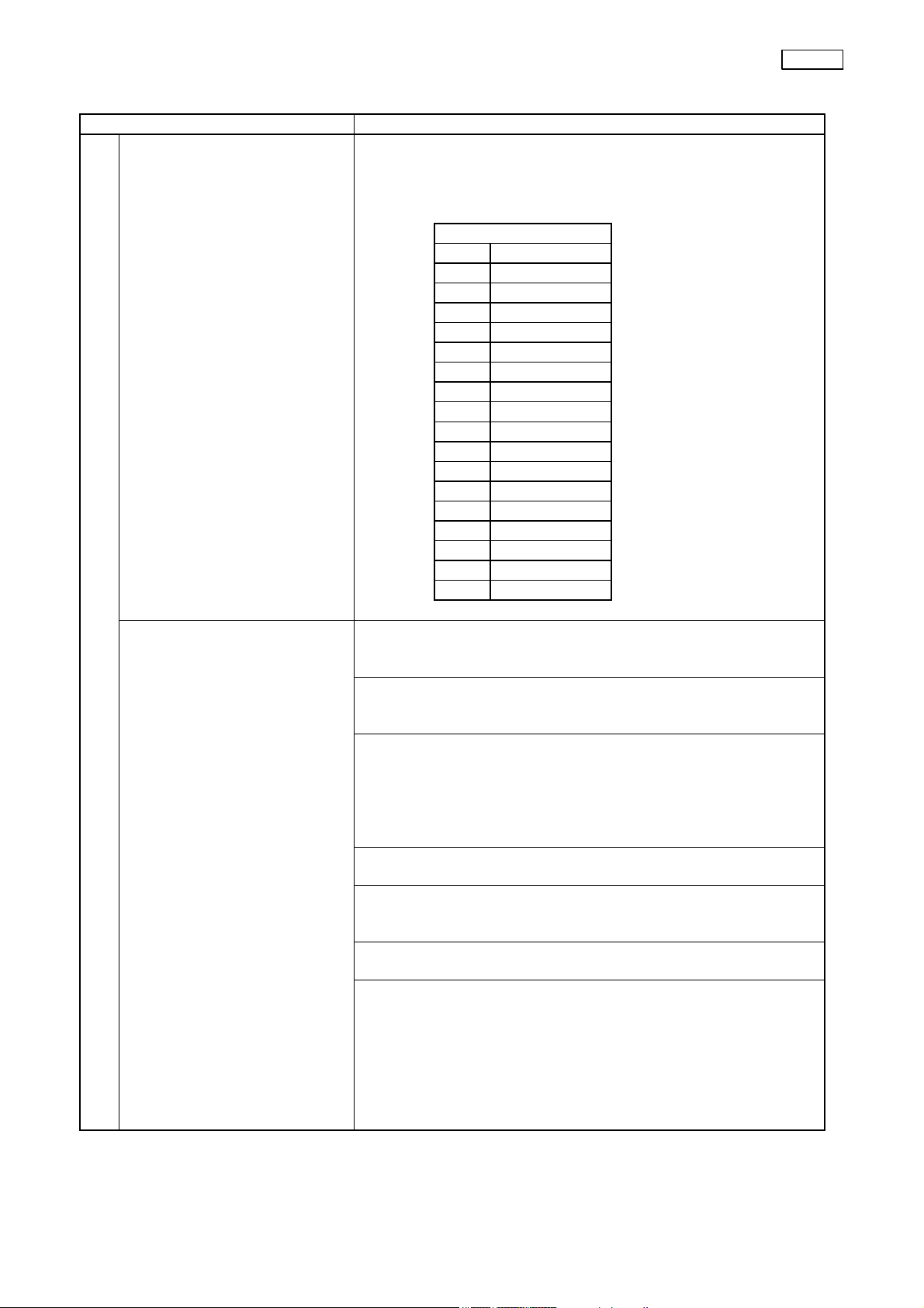
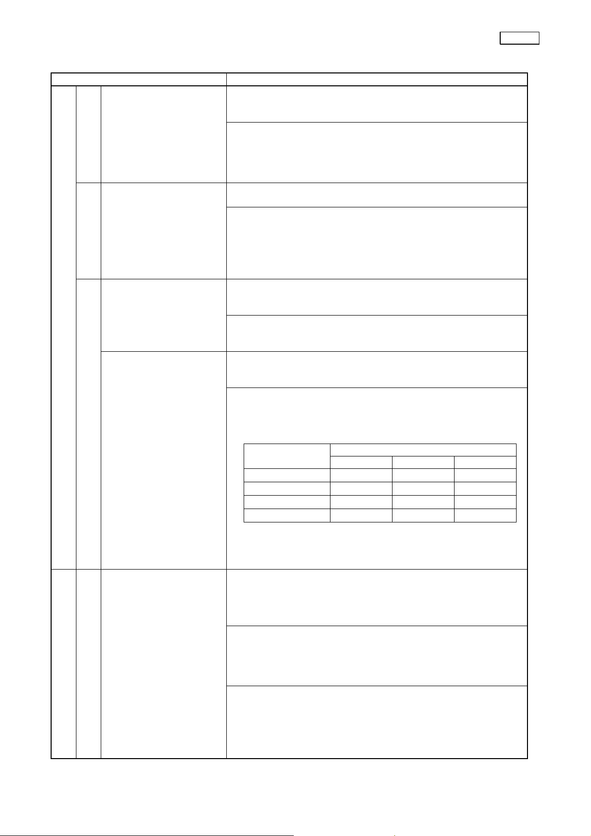
2. Light control output signal 2. Output signal level
The output signal level for the automatic light control of an
applicable light source is defined by the following input
standard.
3. Power supply
3. Input/output conditions
1. Type
(1) 100V class: North America (OAI), Asia 1 (OLA)
(2) 200V class: Europe (OE), Asia 2 (OLA)
2. Rated voltage and input current
(1) 100V class: 100 to 120V, 1.0A
(2) 200V class: 220 to 240V, 0.5A
3. Voltage fluctuation
• The unit performance shall be guaranteed within ±10% of
the rating.
• The unit operation shall be guaranteed within ±15% of the
rating and the temperature increase in ordinary operation
of IEC.
4. Frequency
• 50/60Hz
5. Frequency fluctuation
• The unit performance shall be guaranteed with ±1Hz of
the rating.
6. Power consumption
• 240VA
7. Power cable
(1) 100V class (3 ±0.05m cord set)
3-pin hospital grade plug
(2) 200V class (3.2m cord set)
3-pin plug-less with uneven end
(Attach an appropriate plug in the destination.)
Input signal [mV]
F 30 or more
1 15
2 12.6
3 10.8
4 9.1
5 7.5
6 6.3
7 5.4
8 4.5
9 3.8
10 3.2
11 2.7
12 2.3
13 1.9
14 1.6
15 1.4
16 1.2
17 0.95
SPECIFICATIONS CV-160
1-2
Page 6
1. Type of observation
1. Observation image display position
1. White balance
4. Observation
2. Front panel picture quality adjustment
SPECIFICATIONS CV-160
Item Specification
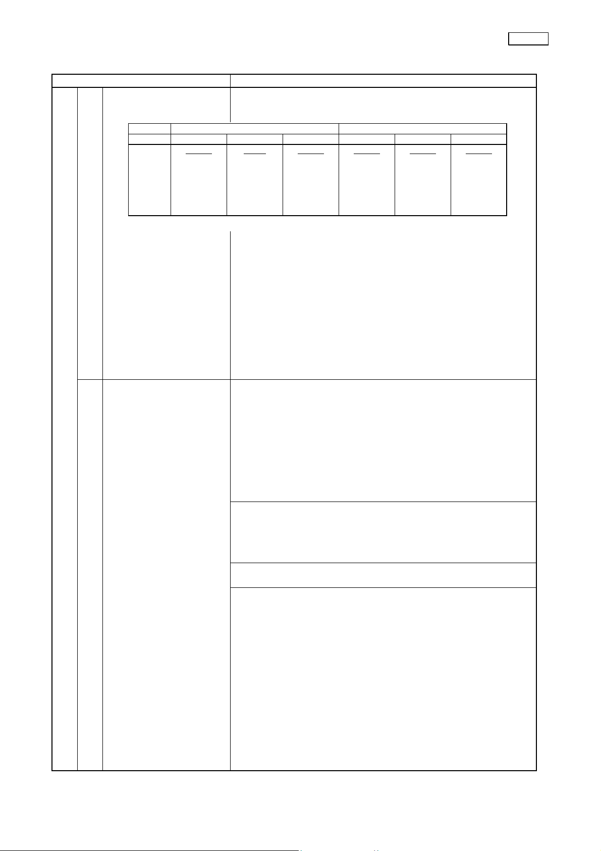
The user can select the endoscopic image display size from the
image
followings depending on the scope (CCD) applied.
North America specification (NTSC) Europe specification (PAL)
CCD 3700,01,08 3704 37071 3700,01,08 3704 37071
Display
size
2 steps
Medium
↓
Full-height
1 step
Full-high
only
2 steps
Semi
full-height
↓
Full-height
2 steps
Small
↓
Medium
2 steps
Small
↓
Medium
3 steps
Medium
↓
Semi
full-height
↓
Full-height
Note 1)
Change the display size on the keyboard or with the scope
switch or RS-232C communication.
Note 2)
Standard setting is as follows.
• 3700/01/08: NTSC = Medium
PAL = Medium
• 3704: NTSC = Full-height
PAL = Semi full-height
• 37071: NTSC = Small
PAL = Small
1. Specifications
• When replacing the scope with a different type,adjust the
white balance using the supplied white cap.
• A memory function is provided to hold the previous white
balance data even if the power switch is turned off.
• Calibrate the white balance automatically if the scope
with the scope ID function (EVIS EXERA 160 series) is
connected to the CV-160.
Note) It is necessary to calibrate manually again if the light
source changed.
2. Setting method
• Select the type of light source(xenon=CLV/halogen=CLE)
on the system setup screen.
• Depress the white balance switch on the front panel.(It is
not necessary for scopes with the scope ID function.)
3. Switch depression detection time
• Approx. 1 second
4. Time required by correction operation
• Approx. 1 second
1-3
Page 7
2. Automatic light
3. Edge enhancement
4. Structure
4. Observation
2. Front panel picture quality adjustment
Item Specification
1. Specification
control
enhancement
1. Selection of
adjustment
color
2. Red group color
adjustment
(when R is
selected)
5. Color tone adjustment
• Switch the peak/average iris mode depending on a subject.
2. Standard setting: Average
3. Setting method
(1) Switch on the front panel
(2) Scope switch
(3) RS-232C communication
Note) Assign the scope switch on the user preset screen.
1. Specification
A subject image is enhanced in three steps (Low/Med./High).
2. Standard setting: Low
3. Setting method
(1) Set the edge enhancement mode (Enh.Type: Edg.) on
the user preset screen.
(2) Switch on the front panel
(3) Scope switch
(4) RS-232C communication
1. Specification
A subject image is enhanced in three steps
(Low/Med./High).
2. Standard setting
The standard setting of each level:
Low:Level1, Med.:Level3, High:Level5
3. Setting method
(1) Set the structure enhancement mode (Enh.Type: Str.)
on the user preset screen.
(2) Select the set value (Level 0 to 8) for each enhancement
level (L/M/H) on the user preset screen.
(3) Switch on the front panel
(4) Scope switch
(5) RS-232C communication
1. Specification
Desired color can be selected.
(Select from four types of R, B, C and Light off.)
2. Standard setting
Light off (not selected)
3. Setting method
Color tone selector switch on the front panel
(Each time the switch is depressed, the color is changed in
the order of R, B, C, Light off and R.)
1. Specification
Color tone of red group can be adjusted.
2. Standard setting
Center of the variable range (±0 step)
3. Setting method
(1) Adjust with the color tone adjustment switch on the
front panel.
(2) Adjust with RS-232C communication.
4. Variable range
±7 steps
(LED indicates step values on the front panel.)
SPECIFICATIONS CV-160
1-4
Page 8
2. Front panel picture quality adjustment
6. Reset switch
4. Observation
1. AGC
2. γ (contrast)
3. Other picture quality adjustment
Item Specification
3. Blue group
color
adjustment
(when B is
selected)
4. Color density
adjustment
(when C is
selected)
5. Color tone adjustment
1. Specification
Color tone of blue group can be adjusted.
2. Standard setting
Center of the variable range (±0 step)
3. Setting method
(1) Adjust with the color tone adjustment switch on the
front panel.
(2) Adjust with RS-232C communication.
4. Variable range
±7 steps
(LED indicates step values on the front panel.)
1. Specification
Color density (chroma) can be adjusted without changing the
hue.
2. Standard setting
Center of the variable range (±0 step)
3. Setting method
(1) Adjust with the color tone adjustment switch on the
front panel.
(2) Adjust with RS-232C communication.
4. Variable range
±7 steps
(LED indicates step values on the front panel.)
1. Specification
The output image to the observation monitor is changed to
the scope image, and the light control, edge/structure
enhancement and color tone and contrast etc. are set on
User Preset 1.
2. Setting method
Press the reset switch on the front panel. (Depress the
switch more than 1 second)
1. Specifications
Turn ON/OFF as needed, depending on the endoscopic
image.
2. Standard setting: ON
3. Setting method
(1) Switch with the keys (Shift + F2 key) on the keyboard.
(2) Switch with the scope switch.
(3) Switch with RS-232C communication.
Note) Assign the scope switch on the user preset screen.
1. Specifications
Selectable from the three modes.
Normal :Ordinary observation
Low :Low contrast mode
(Brighten the dark portion, and darken the bright
portion.)
High :High contrast mode
(Brighten the bright portion, and darken the dark
portion.)
2. Standard setting: ON
3. Setting method
(1) Select with the keys (Shift + F5 key) on the keyboard.
(2) Switch with the scope switch.
(3) Switch with RS-232C communication.
Note) Assign the scope switch on the user preset screen.
SPECIFICATIONS CV-160
1-5
Page 9
3. Freeze
3. Other picture
quality adjustment
1. Display area change
(Electric
function
4. Image display
1. Standard chart image
4. Observation
5. Picture quality
2. Selection of output
5. Input/Output switching function
1. Luminance
1. Resolution
Item Specification
1. Specifications
Make a moving image a still image.
(Field freeze system)
2. Setting method
(1) Freeze with the freeze switch on the keyboard.
(2) Freeze with the scope switch.
(3) Freeze with RS-232C communication.
Note) Assign the scope switch on the user preset screen.
1. Specifications
(1) The observing image size is selectable.
magnification)
output
signal to the monitor
Horizontal resolution
(Magnify in the
horizontal direction
so that the aspect
ratio (H:V) becomes
4:3 with the vertical
magnification rate of
1X, and adjust the
view angle.)
2. Setting method
(1) Set with the switch (Function key F5) on the keyboard.
(2) Change with the scope switch.
(3) Change with RS-232C communication.
Note) Assign the scope switch on the user preset screen.
1. Specifications
100% Color bar is displayed on the screen for adjustment of
the monitor.
2. Setting method
(1) Select with the key (Function key F2) on the keyboard.
(2) Select with RS-232C communication.
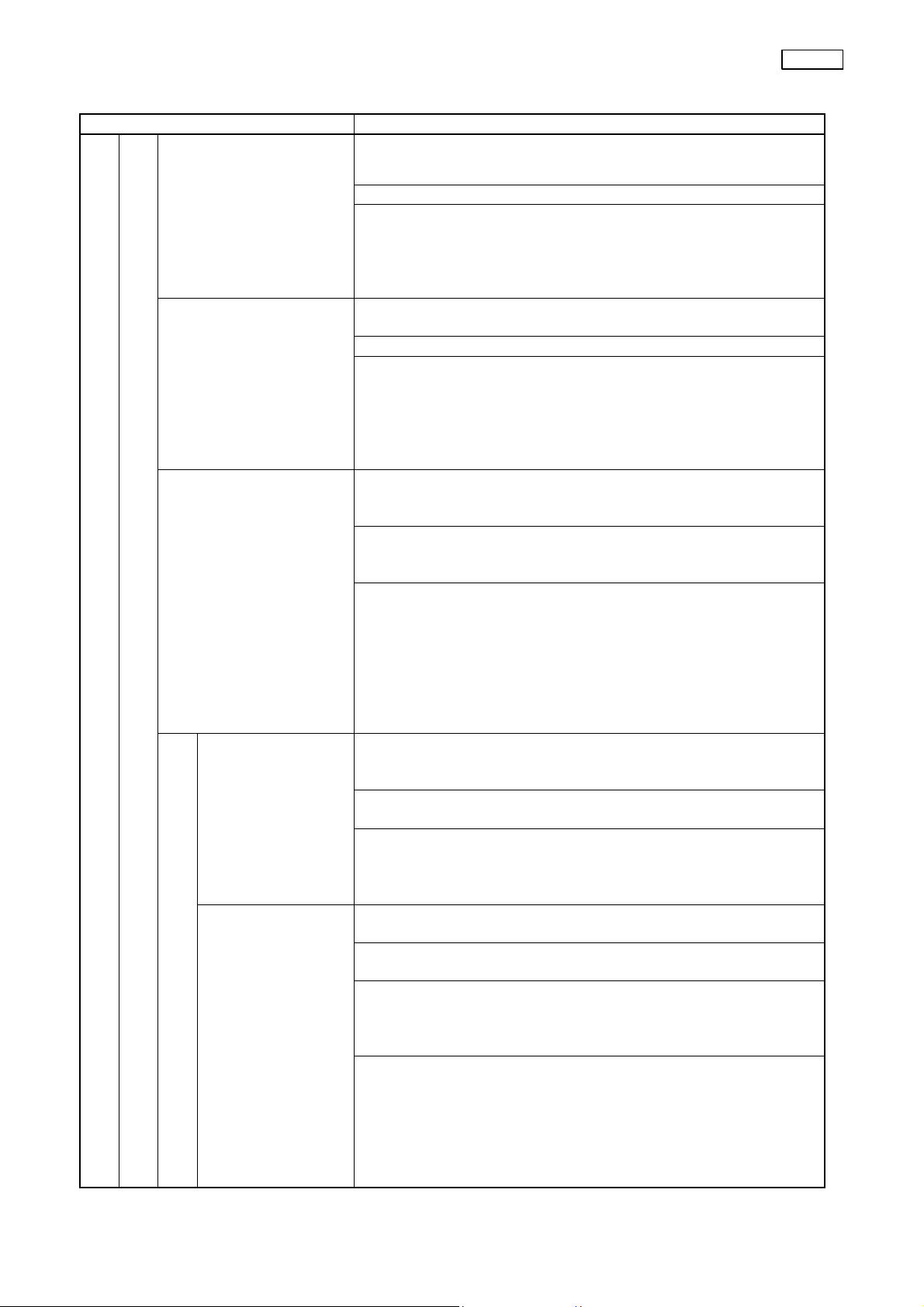
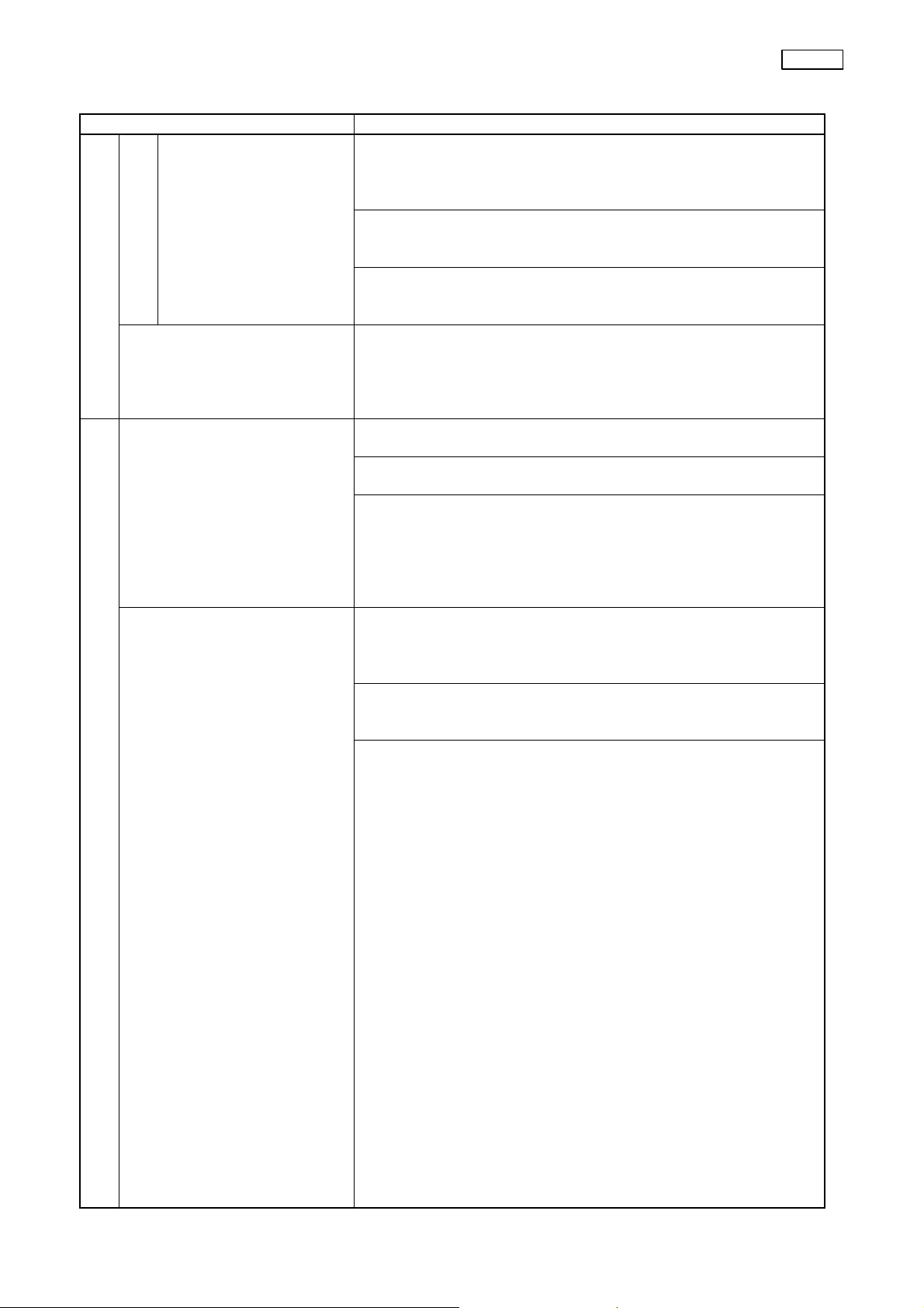
1. Specifications
(1) Select the signal to the monitor from the inputs (scope,
printer, VTR and digital file).
2. Setting method
(1) Select with the switch on the front panel (Image
Source).
(2) Select with RS-232C communication.
SOURCE
SCOPE
PRINTER
VTR
D.F.
・The scope image is displayed at marked ×.
・Switching the monitor image is controlled by the monitor
remote signal.
Near the center:
1. 3700/01/08
(1) Composite signal, RGB signal, Y/C signal outputs
(240TV lines or more)
2. 3704
(1) Composite signal output
(350TV lines or more)
(2) RGB signal, Y/C signal outputs
(400TV lines or more)
3. 37071
(1) Composite signal, RGB signal, Y/C signal outputs
(400TV lines or more)
Output to the monitor IMAGE
RGB Y/C VBS
○ ○ ○
× × ○
× ○ ○
○ × ×
SPECIFICATIONS CV-160
1-6
Page 10
Item Specification
2. Luminance
Vertical resolution
(Magnify in the
horizontal direction
so that the aspect
ratio (H:V) becomes
1. Resolution
5. Picture quality
2. S/N 1. (37dB or more)
1. Registration and access of
2. Recording and displaying
6. Recording
4:3 with the vertical
magnification rate of
1X, and adjust the
view angle.)
patient data
of patient data
Near the center:
1. 3700/01/08
(1) Composite signal, RGB signal, Y/C signal outputs
2. 3704
(1) Composite signal, RGB signal, Y/C signal outputs
3. 37071
(1) Composite signal, RGB signal, Y/C signal outputs
[Conditions]
AGC: OFF
Contrast: Normal
Image enhancement: Edge enhancement (Low)
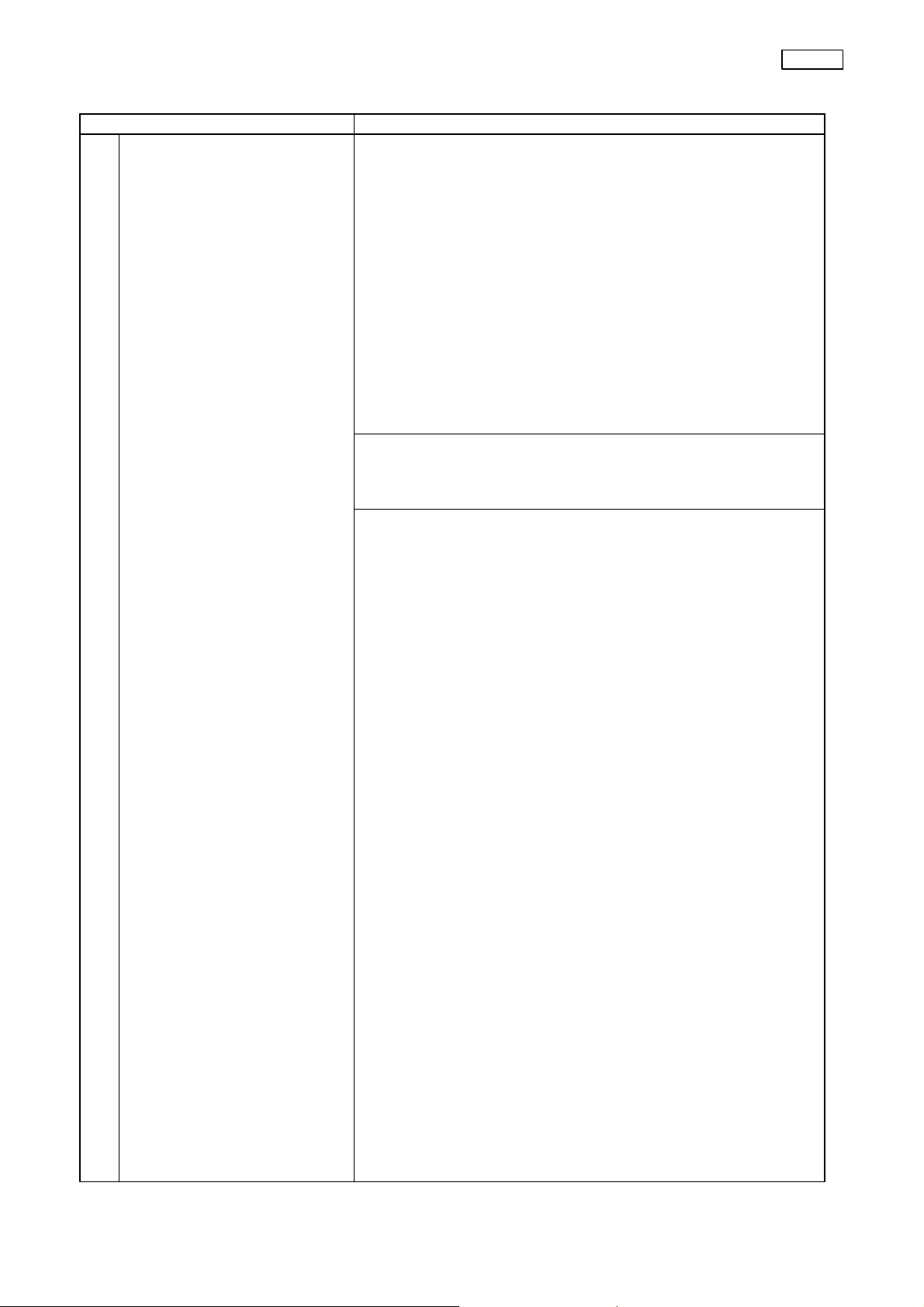
1. Specifications
40 patient data can be registered and accessed.
2. Setting method
Input from the keyboard on the patient data screen.
3. Input items
(1) ID No.
(2) Patient name
(3) Sex and age
(4) Date of birth (Date of inspection is automatically
1. Specifications
The patient data to register, the comment to input after
registration, the number of video print, etc. can be displayed
on the screen.
2. Setting method
(1) Input from the keyboard.
(2) Input with RS-232C communication.
3. Display items
(1) ID No.
(2) Patient name
(3) Sex and age
(4) Date of birth
(5) Date of inspection, time (stopwatch)
(6) Comment
(7) Dr. name
(8) (Video print number/divided number)
(9) (Image enhancement mode: Enhance level)
(10) (Contrast mode)
Note) Only the item in ( ) is indicated.
(320TV lines or more)
(320TV lines or more)
(320TV lines or more)
displayed.)
SPECIFICATIONS CV-160
1-7
Page 11
Item Specification
3. Control of the recording
unit (video printer)
6. Recording
1. Specifications
(1) #PER PAGE
The dividing mode of the video printer connected to the
CV can be switched to 1/2/4/N (N: User setting) mode.
(2) DEL IMAGE
Delete the divided image stored in the printer, then
return the cursor to the previous position.
(3) PRINT
Print out the image stored in the printer.
(4) PRINT QTY.
The number of prints can be switched to 1/2/4/N(N:User
setting) mode.
(5) Data can be stored also during printing. Print image can
be confirmed.
Note) Print out automatically after capturing the images set
up in (1).
2. Setting method
(1) Select the type of printer.
(2) Control with the exclusive key(PRINTER REMOTE) on
the keyboard.
3. Applicable video printer
* NTSC:
OEP (OLYMPUS)
OEP-3 (OLYMPUS)
UP-2900MD (SONY)
UP-2950MD (SONY)
[UP-1800 (SONY)]
[UP-1850 (SONY)]
[UP-5000MD (SONY)]
[UP-5200MD (SONY)]
[UP-5250MD (SONY)]
* PAL:
OEP (OLYMPUS)
UP-2800P (SONY)
UP-2850P (SONY)
[UP-1800 EPM(SONY)]
[UP-1850 EPM (SONY)]
[UP-5000MDP (SONY)]
[UP-5200MDP (SONY)]
[UP-5250MDP (SONY)]
UP-2100P
Note) [ ] Products already sold.
Remote cable: MH-995 (RS-232C)
MAJ-854 (X-contact)
SPECIFICATIONS CV-160
1-8
Page 12
SPECIFICATIONS CV-160
Item Specification
4. VTR recording/playback
control
6. Recording
5. Release continuous
recording
1. Scope Connect the scope and CV-160 with the scope cable(MAJ-843).
2. OES video converter Can be directly connected to the CV-160.
7. Connection
1. Display (1) English 100 to 120V: NTSC (OAI, OLA 1)
2. Structure Dripproof required as medical equipment.
8. Panel
1. Specifications
The following operations are possible from the exclusive key
on the keyboard, RS-232C and scope switch for the VTR
connected to the CV.
• Recording(REC)
• Playback(PLAY)
• Stop(STOP)
• Fast forward(FWD)
• Rewind(REW)
• Pause(PAUSE)
• Fast forward during playing (RS-232C control only)
• Rewind during playing (RS-232C control only)
2. Setting method
(1) Use the exclusive key on the keyboard.
(2) Use the scope switch.
Note) Scope switch can control [REC/REC_PAUSE] only.
(Scope switch is assigned to [VTR]).
3. Applicable VTR
* NTSC
VO-7600 (SONY)
VO-9600 (SONY)
SVO-9500MD (SONY)
[BR-S611 (JVC)]
[BR-S811 (JVC)]
* PAL
VO-7630 (SONY)
VO-9600P (SONY)
SVO-9500MDP (SONY)
[BR-S611E (JVC)]
[BR-S811E (JVC)]
1. Specifications
Release of each connected unit can be controlled from the
CV-160.
2. Setting method
(1) Release with the scope switch.
(2) Release from the keyboard.
Note) Assign the scope switch on the user preset screen.
3. Controllable units
(1) Applicable video printers
(2) Applicable digital files
220 to 240V: PAL (OLA 2)
(2) Symbol 220 to 240V: PAL (OE)
1-9
Page 13

SPECIFICATIONS CV-160
Item Specification
3. Storage (1) Storage items
Color tone set value
Image enhancement level
8. Panel
1. Panel To remove dust, dirt, and non-patient debris, wipe the unit
9. For cleaning
1. Laws and regulations
applied
10. Safety
Iris mode,
White balance data.
using a soft, lint-free cloth moistened with 70% ethyl or
isopropyl alcohol. If the unit is soiled with blood or other
potentially infectious materials, first wipe off all gross debris
using neutral detergent and then decontaminate its surface
using lint-free cloth moistened with 70% ethyl or isopropyl
alcohol.
Country/area
1. EU/FETA MDD Class: Class I
3. Japan/
Korea
Classification of medical
instruments
OAI/Asia Protection type against an
Laws and
regulations applied
Medical Equipment
Safety Laws (510K)
UL/C-UL UL544
The Drugs,
Cosmetics and
Medical
Instruments Act
General name:
Light source,
processor
Approval No.
07BZ0043
Standards to be
conformed to
EN 60601-1
EN 60601-1-1
EN 60601-1-2
EN 60601-1-2-18
IEC 513
IEC 529
ISO 9000-3
ISO 3740
ISO 8600-1
ISO 8600-1.3
Class: Class II 2. USA
CSA22.2 No. 125
JIST1001 (medical
electronics safety)
JIST1002 (medical
electronics safety test)
electrical shock: Class I
Protection level against
an electrical shock: BF
type
1-10
Page 14

Item Specification
1. Laws and regulations
applied
10. Safety
1. Dimensions (maximum
outer dimensions)
2. Weight 8kg
3. Standard setting of
display/function
11. Others
SPECIFICATIONS CV-160
EU area (OE) Protection type against an
electrical shock:
Class I
Protection level against
an electrical shock:
BF type
Note) When the fitting
part has no
indication of
protection level
against an electric
shock, it is the BF
type fitting part.
370 (W) × 72 (H) × 420 (D) mm
Front panel
Front Panel
Function/dis
play
Image
selection
(IMAGE
SOURCE)
IRIS AVE
ENH L
R ±0 ±0 Stored
B ±0 ±0 Stored
C ±0 ±0 Stored
SELECT Not selected Not selected Not selected
WB – (Cleared) Stored Stored
Factory
setting
SCOPE SCOPE SCOPE
Reset Power ON
User Preset1
IRIS
User Preset1
ENH.Pos.
Stored
Stored
1-11
Page 15

3. Standard setting of
display/function
11. Others
SPECIFICATIONS CV-160
Item Specification
System Setup
System setup
Function/dis
play
[Printer]
Type
Qty.,”N”
Caption
[Release
Time]
Printer
D.F.
[Clock]
Date
Time
Disp.
[Patient
Data]
[Remote
Control]
Mon. Type
Mon. VTR
VTR
[Light
Source]
[Network]
Use DHCP
IP Address
Net Mask
Factory
setting
OEP
4
– (Cleared)
0.5
2
Note 1
Note 1
Note 1
Resume Stored Stored
OEV2
S-Video
RS-232C
CLV Stored Stored
No
Note 2
255.255.255.0
Reset Power ON
Stored
Stored
Stored
Stored
Stored
Stored
Stored
Stored
Stored
Stored
Stored
Stored
Stored
Stored
Stored
Stored
Stored
Stored
Stored
Stored
Stored
Stored
Stored
Stored
Stored
Stored
Stored
Stored
Note 1) Set to the local time on shipment.
Note 2) The high order 3-byte of the initial IP address is
192.168.0. The lower order 1-byte is the fixed value
for each CPU number.
User Preset
Function/display
[Scope Switch]
Switch1
Switch2
Switch3
Switch4
[Image Size]
160
Q160
XP160
[Image Control]
User Preset
Iris
AGC
Contrast
Enh.Pos.
Enh.Type
Enh.Low
Enh.Med.
Enh.High
Factory
setting
Freeze
Iris
Enhance
Release
Medium
Semi-Full
Small
Ave
On
Normal
Low
Str.
1
3
5
Reset Power ON
Stored
Stored
Stored
Stored
Stored
Stored
Stored
Stored
Stored
Stored
Stored
Stored
Stored
Stored
Stored
Stored
Stored
Stored
Stored
Stored
Stored
Stored
Stored
Stored
Stored
Stored
Stored
Stored
Stored
Stored
1-12
Page 16

3. Standard setting of
display/function
11. Others
SPECIFICATIONS CV-160
Item Specification
Patient Data
Function/display
ID No.
Name
Sex
D.O.Birth
Age
Patient Data
Phy.Name
Factory
setting
Cleared
Cleared
Cleared
Cleared
Cleared
Cleared
Reset Power ON
Stored
Stored
Stored
Stored
Stored
Stored
Stored
Stored
Stored
Stored
Stored
Stored
Scope Info.
(1) For the user
Function/display
[Scope Infomation]
Scope Model
Serial No.
Comments
Cumulative Uses
Check Period
Service Contract
Warranty Date
Scope Information
Owner
Customer ID No.
ID Ver.
Factory
setting
Stored
Stored
Cleared
Cleared
180
Cleared
Cleared
Cleared
Cleared
Cleared
Reset Power ON
Stored
Stored
Cleared
Stored
Stored
Stored
Stored
Stored
Stored
Stored
(Data read
out from
the scope)
(2) For service
Function/display
[Scope Infomation]
Scope Model
Serial No.
Comments
Cumulative Uses
Check Period
Service Contract
Warranty Date
Owner
Customer ID No.
ID Ver.
Mfg. Comments
Ctrl+Shift+Scope Information
Service Comments
Repair Info.
Checkup Info.
Factory
setting
Stored
Stored
Cleared
Cleared
180
Cleared
Cleared
Cleared
Cleared
Cleared
Cleared
Cleared
Cleared
Cleared
Reset Power ON
Stored
Stored
Cleared
Stored
Stored
Stored
Stored
Stored
Stored
Stored
Stored
Stored
Stored
Stored
(Data read
out from the
scope)
* Press the Ctrl + Shift + Scope Info. keys on the keyboard to
shift from the Scope Information screen to the above screen.
1-13
Page 17

3. Standard setting of
display/function
11. Others
SPECIFICATIONS CV-160
Item Specification
Hidden screen
Function/display
[Shipping]
Country
[Printer]
Print Time
Auto Clear
[Color]
Mon.Red
Mon.Blue
Prt.Red
Prt.Blue
[Clock]
Total
Trim
Ctrl+Shift+Systemsetup
[CPU Board]
Serial No.
[Video Board] – Stored Stored
[Pat.Board]
Iris spd.
Iris L
Iris D
Factory
setting
Destination Stored
40
ON
±0
±0
±0
±0
–
±0
-
–
Med.
1
1
Reset Power ON
Stored
Stored
Stored
Stored
Stored
Stored
Stored
Stored
Stored
Stored
Stored
Stored
Stored
Stored
Stored
Stored
Stored
Stored
Stored
Stored
Stored
Stored
Stored
Stored
Stored
Press the Ctrl + Shift + System Setup keys on the keyboard to
shift from the System Setup screen to the above screen.
1-14
Page 18

1
OLYMPUS
2
3
4
5
8
9
10
11
12
VTRREMOTE
123456789
101112131415161718
A A
YOUTVTR
NOUTVTR
COUTVTR
YINVTR
NINVTR
CINVTR
(NC)
VTR6V
PLAYCMD
FFCMD
RECCMD
STOPCMD
REWCMD
PAUSECMD
(J1)
20212223242526272829303132333435363738394041424344454647484950515253545556575859606162
19
STOPLVL
REC239
TXDVTR
RTSVTR
DSRVTR
(NC)
(NC)
(NC)
(NC)
(NC)
(NC)
(NC)
(NC)
(NC)
(NC)
(NC)
(NC)
(NC)
(NC)
(NC)
(NC)
(NC)
(NC)
(NC)
(NC)
(NC)
(NC)
(NC)
GND
GND
GND
GND
GND
GND
GND
(J2)
(J3)
GND
PLAYTAL
FFTAL
RECTAL
STOPTAL
REWTAL
PAUSETAL
TAL239
RXDVTR
CTSVTR
DTRVTR
(NC)
(NC)
UPCV16PNDF
(J2)
NCNCNCNCGND1DF
RXDDF
123456789
TXDDF
CTSDF
RTSDF
DTRDF
GND2DF
101112131415161718
DSRDF
RELDF
DMR2DF
GND3DF
UPCV16PNRP
PRIMARY
B B
SECONDARYCIRCUIT
C C
CIRCUIT
+12V
GND
121
2
DCFAN
YOUTVTR
GND
NOUTVTR
GND
COUTVTR
GND
YINVTR
123456789
GND
NINVTR
GND
CINVTR
GNDNCNCNCNCNCNC
101112131415161718
NC
GND
GND
VTR6V
PLAYCMD
PLAYTAL
FFCMD
123456789
FFTAL
RECCMD
RECTAL
STOPCMD
STOPTAL
REWCMD
REWTAL
PAUSECMD
101112131415161718
PAUSETAL
STUPLVL
TAL239
REC239
GND
20212223242526
19
RXDVTR
TXDVTR
CTSVTR
RTSVTR
DTRVTR
DSRVTR
POWER
SUPPLY
PATIENTCIRCUIT
D D
R‑EESIG
R‑EEGND
R‑EE+5V
ABC
123
4
R‑EEGND
R‑EE+5V
GND
UPCV16AP
(J202)
GND
CCDSIG
GND
4
4
3
VOUT
1234567
+8V
GND
‑10.5V
‑15V
GND
(J200)
SW1
SW2
SW3
SW4
COM(+5V)
LIVE1
123456789
123456789
BRN
23
SW1
F‑EE
RED
ORN
YEL
PNK
BLU
24
22
30
13
14
11
SW2
SW3
SW4
COM
KENCHI
EE+
CONNECTORBROCKU
+19V
GND
12
EE‑
+5V
WHT
SCID
PRP
26
SCOPEID
(J201)
φR
GND
φH2
LIVE3
123456789
10
123456789
10
18596
LIVE3φRNC
φH2NCφH1
GND
φH1
10
GND
φV1
GND
φV3
GND
φV2
GND
φV4
101112131415161718
101112131415161718
29
2119202827
φV1
GNDφV1
φV3
GNDφV3
φV2
GNDφV2
GND
φVSUBVL+15V.CCD
GND
BRN
RED
YEL
BLK
7
2
18
17
16
φV4
GNDφV4
φVSUBVL+15VCCD
15
GND
GND.P
GND.P
25
GND.P
GND
GND
#FFPCLR
FPDATA
FFPCLK
#FFPSTB
FPDOUT
DMY
GND
CAPACITOR1603EU
GND
+5V
+5V
+5V
+5V
GND
GND
GND
GND
PANEL
SHEET160
FLED
GND
FERRITE
GND
+5VP
GND
2PCLK
GND
PCLK
GND
+5VF
GND
+5VF
(J205)
GND
AD9
GND
AD8
GND
AD7
GND
AD6
(J207)(J2)
FLAT
CORE
1
2
3
4
5
6
7
8
9
10
11
12
13
14
15
16
17
18
1
2
GND
GND
#FFPCLR
FPDATA
FFPCLK
#FFPSTB
FPDOUT
DMY
GND
GND
+5V
+5V
+5V
+5V
GND
GND
GND
GND
12FLED
GND
(J1)(J1)
1
2
3
4
5
6
7
8
9
10
11
12
13
14
15
16
17
18
1
1
2
2
AD5
AD4
AD3
AD2
AD1
AD0
FPDIN
FPCK
FPDOUT
#FPCLR
OVD
PTCLK
PTDIN
PTDOUT
IDRX
IDTX
CJD4
CJD3
CJD2
CJD1
CJD0
VRTIM
(J206)
UPCL16ZZ
CORE
10
10
9
9
8
8
7
7
6
6
5
5
4
4
3
3
2
2
1
1
1
2
3
4
5
6
7
8
9
10
11
12
13
14
15
16
17
18
19
20
21
22
23
24
25
26
27
28
29
30
FLAT
CORE
E E
12341234567
R‑EESIG
(J204)
F F
LIVE2/DMY
(J203)
123
123
G G
4
H H
VDMY
NC(TXDSCV)
ENDE
DATEDF
(J1)
NC
18
NC
17
NC
16
NC
15
NC
14
NC
13
GND
12
CINVTR
11
GND
10
NINVTR
9
GND
8
YINVTR
7
GND
6
COUTVTR
5
GND
4
NOUTVTR
3
GND
2
YOUTVTR
1
1
+5V
1
2
GND
2
1
+6VA
1
2
GND
2
3
‑5VA
3
1
1
+5VP
2
2
GND
3
3
2PCLK
4
4
GND
5
5
PCLK2
6
6
GND
7
7
+5VF
8
8
GND
9
9
+5VF
GND
10
10
1
GND
2
AD9
3
GND
4
AD8
5
GND
6
AD7
7
GND
8
AD6
9
AD5
AD4
10
AD3
11
AD2
12
AD1
13
AD0
14
FPDIN
15
FPCK
16
FPDOUT
17
#FPCLR
18
OVD
19
PTCLK
20
PTDIN
21
PTDOUT
22
IDRX
23
IDTX
24
CJD4
25
CJD3
26
CJD2
27
CJD1
28
CJD0
29
VRTIM
30
GND1DF
TXDDF
RISDF
GND2DF
RELDF
GND3DF
ENDF
RXDDF
CTSDF
DTRDF
DSRDF
DMR2DF
NC(TXDSCV)
DATADF
1
2
3
4
5
6
7
8
9
10
11
12
13
14
(J9)
(J5)
(J4)
(J2) (J1)
DFREMOTE
DATEDF
18
ENDF
17
NC(TXDSCV)
16
GNDDF
15
DMR2DF
14
DMR1DF
13
DSRDF
12
GNDDF
11
DTRDF
10
RTSDF
9
CTSDF
8
TXDDF
7
RXDDF
6
GNDDF
5
NC
4
NC
3
NC
2
NC
1
DSRVTR
26
DTRVTR
25
RTSVTR
24
CTSVTR
23
TXDVTR
22
RXDVTR
21
GNDVTR
20
REC239
19
TAL239
18
STUPLVL
17
PAUSETAL
16
PAUSECMD
15
REWTAL
14
REWCMD
13
STOPTAL
12
STOPCMD
11
RECTAL
10
RECCMD
9
EETAL
8
EECMD
7
PLAYTAL
6
PLAYCMD
5
VTR6V
4
GNDVTR
3
GNDVTR
2
NC
1
(J11)
121
+5V
2
GND
(J1)
EVRDIN
EVRDIN
(J3)
REMOTE
1234567812345678123
MON1
MON2
MON3
MON4
MON5
MON6NCGNDMON
VBUSKB1
D‑KB1
ENCCLK
EVRDOUT
EVRCLK
ENCCLK
EVRDOUT
EVRCLK
(J9)
#ZOOMCS
#ENHCS
ENCDATA
#ZOOMCS
#ENHCS
ENCDATA
#LPE1CS
#LPE2CS
#GAMCS
#LPE1CS
#LPE2CS
#GAMCS
(J6)(J8)
#MAT1CS
#MAT2CS
#MAT1CS
#MAT2CS
#PORT2
#WBCS
#PORT2
#WBCS
(J3)
#WRI
#ROM
#PORT1
#WRITE
#ROM
#PORT1
D+KB1
#RD
#READ
GNDKB1
VBUSKB2
D‑KB2
D+KB2
GNDKB2
UPCV16CP
CPUADR3
CPUADR2
CPUADR1
CPUADR0
#RESET
CPUADR3
CPUADR2
CPUADR1
CPUADR0
#CPURESET
VBUSPC
(J4)
CPUADR6
CPUADR5
CPUADR4
CPUADR6
CPUADR5
CPUADR4
4
D‑PC
D+PC
GNDPC
CPUADR9
CPUADR8
CPUADR7
CPUADR9
CPUADR8
CPUADR7
NETWORKPCKEYBOARDMONITOR
1234567
TD+
TD‑
(J5)
CPUADR13
CPUADR12
CPUADR11
CPUADR10
CPUADR13
CPUADR12
CPUADR11
CPUADR10
RD+NCNC
RD‑NCNC
CPUADR17
CPUADR16
CPUADR15
CPUADR14
CPUADR17
CPUADR16
CPUADR15
CPUADR14
8
CPUADR19
CPUADR18
proprietary and Confidential
123456789
GNDCVP
TXDCVP
RTSCVP
(J7)
CPUDATA3
CPUDATA2
CPUDATA1
CPUDATA0
CPUADR20
CPUDATA3
CPUDATA2
CPUDATA1
CPUDATA0
NCNCCPUADR18
PRINTER
REMOTE
GNDCVP
DMRICVP
GNDCVP
ENCVP
GND
GND
GND
GND
CK27M
CK27MGND
#HD
#VD2
ODD
CSYNC
#CK13M
#CK13MGND
#VD1
LCADATA
LCACLK
NC(INIT)
NC(TCK)
NC(TMS)
NC(TDO)
NC(TD1)
GND
GND
GND
GND
YMAIN7
YMAIN6
YMAIN5
YMAIN4
YMAIN3
YMAIN2
YMAIN1
YMAIN0
PRMAIN7
PRMAIN6
PRMAIN5
PRMAIN4
PRMAIN3
PRMAIN2
PRMAIN1
PRMAIN0
PBMAIN7
PBMAIN6
PBMAIN5
PBMAIN4
PBMAIN3
PBMAIN2
PBMAIN1
PBMAIN0
GND
GND
GND
GND
YMIX7
YMIX6
YMIX5
YMIX4
YMIX3
YMIX2
YMIX1
YMIX0
PRMIX7
PRMIX6
PRMIX5
PRMIX4
PRMIX3
PRMIX2
PRMIX1
PRMIX0
PBMIX7
PBMIX6
PBMIX5
PBMIX4
PBMIX3
PBMIX2
PBMIX1
PBMIX0
GND
GND
GND
GND
(J2)
CPUDATA7
CPUDATA6
CPUDATA5
CPUDATA4
CPUDATA7
CPUDATA6
CPUDATA5
CPUDATA4
1011121314
RXDCVP
CTSCVP
DTRCVP
DSRCVP
CJDO
CJD1
CJD2
CJD3
CJD4
CJDO
CJD1
CJD2
CJD3
CJD4
DATE
2000‑04
DMR2CVP
NC(TXDSCV)
DATACVP
1
1
GND
2
2
IDRX
IDRX
PTDUMMY
IDTX
NC
IDTX
3
4
5
6
7
8
9
10
10
11
11
12
12
13
13
14
14
15
15
16
16
17
17
18
18
19
19
20
20
21
21
22
22
23
23
24
24
25
25
26
26
27
27
28
28
29
29
30
30
31
31
32
32
33
33
34
34
35
35
36
36
37
37
38
38
39
39
40
40
41
41
42
42
43
43
44
44
45
45
46
46
47
47
48
48
49
49
50
50
51
51
52
52
53
53
54
54
55
55
56
56
57
57
58
58
59
59
60
60
61
61
62
62
63
63
64
64
65
65
66
66
67
67
68
68
69
69
70
70
71
71
72
72
73
73
74
74
75
75
76
76
77
77
78
78
79
79
80
80
PTDOUT
PTDIN
PTDOUT
PTDIN
GND
3
GND
4
GND
5
CK27M
6
CK27MGND
7
#HD
8
#VD2
9
OABSELS
CSYNC
#CK13M
#CK13MGND
#VD1
TXS0
CCLK
NC(INIT)
NC(TCK)
NC(TMS)
NC(TDO)
NC(TD1)
GND
GND
GND
GND
YMAIN7
YMAIN6
YMAIN5
YMAIN4
YMAIN3
YMAIN2
YMAIN1
YMAIN0
PRMAIN7
PRMAIN6
PRMAIN5
PRMAIN4
PRMAIN3
PRMAIN2
PRMAIN1
PRMAIN0
PBMAIN7
PBMAIN6
PBMAIN5
PBMAIN4
PBMAIN3
PBMAIN2
PBMAIN1
PBMAIN0
GND
GND
GND
GND
YMIX7
YMIX6
YMIX5
YMIX4
YMIX3
YMIX2
YMIX1
YMIX0
PRMIX7
PRMIX6
PRMIX5
PRMIX4
PRMIX3
PRMIX2
PRMIX1
PRMIX0
PBMIX7
PBMIX6
PBMIX5
PBMIX4
PBMIX3
PBMIX2
PBMIX1
PBMIX0
GND
GND
GND
GND
#FPCLR
FPDUMMY
PTCLK
20212223242526272829303132333435363738394041424344454647484950515253545556575859606162636465666768697071727374757677787980
20212223242526272829303132333435363738394041424344454647484950515253545556575859606162636465666768697071727374757677787980
#FPCLR
NC
PTCLK
FPDOUT
FPDIN
19
19
FPDOUT
FPDIN
GND
FPCLK
GND
FPCLK
GND
GND
GND
GND
GND
GND
GND
GND
GND
GND
(J6)
GND
101112131415161718
101112131415161718
GND
GND
GND
+5VD
+5VD
(J11)
PRNTERIN
(J13)
PRINTER
OUT
(J10)
COMPOUT
(J8)
MONITOR
OUT
(J7)
DFOUT
(J7)
DFIN
+5VD
+5VD
UPCV16DP
TITLE MODEL
PRNIN
COMPGND
NC
RGND
RPRN
GPRN
RPRN
GGND
BGND
SPRN
SGND
VBSOUT
COMPGND
RGND
GGND
BGND
SGND
Y/CGND
NC
NC
VBSGND
RMON
GMON
BMON
SMON
YMON
CMON
VBSMON
NC
RGND
RDF
GDF
BDF
GGND
BGND
SYDF
SGND
NC
RGND
RDF
GDF
BDF
GGND
BGND
SYDF
SGND
+5VD
+5VD
+5VD
+5VD
+5VD
+5VD
+5VD
+5VD
CV‑160CONNECTIONDIAGRAM
+5VD
+5VD
123456789
123456789
+5VD
+5VD
Page
1/1
1
2
1
2
3
4
5
6
7
8
9
1
2
1
2
3
4
5
6
7
8
9
10
11
12
13
14
15
1
2
3
4
5
6
7
8
9
1
2
3
4
5
6
7
8
9
1
2
3
4
567
OLYMPUS
OLYMPUS
8
9
10
11
12
2‑1
Page 19

BLOCK DIAGRAM CV-160
BLOCK DIAGRAM
AC IN
VIDEO OUT
VIDEO PROCESS
POWER
SUPPLY
UPCV16AP UPCV16DP
VIDEO PROCESSER
CCD DRIVER
PRE AMP CDS A/D
Cable
Scope
CCD
Scope
REMOTE
CONTROL SIG.
I/F
CPU
UPCV16CP
3-1
Page 20

1. Contents
2. CV-160 troubleshooting
TRUBLESHOOTING CV-160
TROUBLESHOOTING
1. Defective units 4-2
2. Symptoms and object units 4-2
4-1
Page 21

TRUBLESHOOTING CV-160
2. CV-160 troubleshooting
2-1 Defective units
Unit
A AP (patient) board (UPCV16Apxx)
B DP (video) board (UPCV16DPxx)
C CP (CPU) board (UPCV16CPxx)
D FP (front panel) unit
E RP (rear) board
F SWP (power supply) unit
G Connector block unit (including harness)
H AP-DP flat harness
I AP-DP coaxial harness
J AP-FP flat harness
K RP-DP flat harness
L RP-CP flat harness
M DF board & harness (CV-160 only)
N Light control cable harness
O Keyboard
P FPLED (front panel power SWLED) board (UPCL)
2-2 Symptoms and object units
• The following table shows the order of checking doubtful units when a defect occurs.
※ For the relation with the alphabets of the object units, refer to 2-1 Defective units.
No. Symptom
1 Character is blurring. B C
2 Character is fluctuating. B F
3 Character is flying. C
4 Character is not displayed. B C
5 Character is displaced. B C
6 RGB signal is not obtained. B
7 Y/C signal is not obtained. B
8 Composite signal is not obtained. B
9 Keyboard is not accepted. O C
10 Smears A
11
12 Blooming A
13 Mosaic-like noises appear on the scope image. B C A H
14 Digital noises or other noises appear. B A H
15 Horizontal stripes appear on the screen. A B
16 Vertical stripes appear on the screen. A B
17 Vertical wave noises A N F
18 Contour line noises B A C
19 High frequency application noises A
20 Mask shape is defective. C
21 The image in the mask is displaced. H A B
22 The screen is unstable. B A C F
23 Monochrome image is displayed. B C
24 Noises appear on the magnified screen. B C
25
26 Color reproduction of only the RGB signal is bad. B
Single noises appear in the horizontal/vertical
direction.
Color reproductions of RGB, Y/C and composite
signal are bad.
4-2
Order of checking doubtful units
1 2 3 4 5 6
A
B A C
Page 22

TRUBLESHOOTING CV-160
No. Symptom
27 Color reproduction of only the Y/C signal is bad. B
28 Color reproduction of only the composite signal is
bad.
29 The hue is abnormal. J H C D
30 The endoscopic image is not displayed. I H A B F C
31 The endoscopic image is wavering. H A B
32 Image enhancement is strong. B C
33 Image enhancement is weak. B C
34 Image enhancement does not function. B C
35 The AGC malfunctions. A C
36 Latitude is narrow. A B
37 The screen is hunching. A C
38 The screen is dark. N G A
39 The screen is bright. N G A
40 The automatic light control responds late. A C
41 The automatic light control does not function. N G A
42 The digital image is abnormally displayed. B C
43 The screen sways. B C
44 Sandstorm-like noises B C
45 The screen is white. B C
46 The screen is black. B C
47 AGC is not switched. O C A
48 LED is not lit on the front panel. J H F
49 The power switch LED is not lit. J H P F
50 VTR is not controlled. C L E
51 Video printer is not interlocked. C
52 Buzzer does not sound. C
53 Fail to freeze (from the scope switch). G A C B
54 Fail to freeze (from the keyboard). O C B
55 Fail to release the freeze (from the scope switch). G A C
56 Fail to release the freeze (from the keyboard). O C
57 Fail to release (from the scope switch). G A C
58 Fail to release (from the keyboard). O C
59 White balance is invalid. C B A
60 Fail to switch the output. D C B
61 Fail to change the measurement mode. D C A
62 Fail to change the contrast. O C B
63 Color tone step is invalid. J H F C D
64 Data is not stored. C
1 2 3 4 5 6
Order of checking doubtful units
1 2 3 4 5 6
B
4-3
Page 23

DISASSEMBLING/ASSEMBLING PROCEDURE CV-160
DISASSEMBLING/ASSEMBLING PROCEDURE
1. General Precautions on Disassembling/Assembling
• Replace the parts and wires to the original positions.
• For electrical safety and standard, be sure to reassemble the following parts to the original
states.
① Insulation tube and mylar sheet
② Cables clamped and separated from the heating parts or high-voltage parts
③ Cover screws with a toothed lock washer to suppress a radiation noise
• Use the specified parts.
• The parts used in this unit are designed protective against vibration, heat and high voltage. Be
sure to select the parts with the same characteristics from the parts list when replacing the
parts.
• Be careful when disconnecting the cable housing.
• Don’t pull the cable. Be sure to use the special tool.
• Be careful not to be injured.
Some metallic parts have sharp corner or edge. Be careful when handling such parts.
• Be sure to observe the specified torque and dimensions.
Observe the torque and dimensions when they are specified.
As for the H-band which secures each tube, first tighten it by the specified torque and then pull
the tube to check whether the tube becomes loose or it comes off.
• Clean the parts to be used.
When re-using the same parts, eliminate the sealing material and tape and clean. For the
O-ring and packing, clean the surface of the parts on which the O-ring or packing is mounted.
Otherwise, it may cause water leakage.
• Don't forget to tighten the screws and nuts.
Failure in tightening the screws and nuts may cause water leakage.
2. Jigs and Tools
No Name No. Specification Remarks
1
Monkey wrench OT0537
2
Phillips screwdriver No. 2 OT0376
3
Phillips screwdriver No. 1 OT0544
4
Precision screwdriver OT0011
5
Box screwdriver set OT0545
6
L-wrench OT0215
7
8
5-1
Page 24

3. Disassembling Procedure
3-1. Top cover
DISASSEMBLING/ASSEMBLING PROCEDURE CV-160
(1) Remove the eleven screws (HCBK3x6SA)
that secure the top cover.
3-2. Front panel unit
Flexible cord
Top cover
Phillips screwdriver No. 2
(2) Remove the top cover from the main unit.
(1) Remove the flexible cord from the
connector as shown on the left.
(2) Remove the three screws (CCUK3x4SZ)
that secure the front panel unit.
Front panel unit
Phillips screwdriver No. 2
(3) Remove the front panel unit from the
main unit.
5-2
Page 25

3-3. Connector block unit
①
DISASSEMBLING/ASSEMBLING PROCEDURE CV-160
(1) Remove the screw (① CCUK3x6SZ) that
secures the capacitor unit.
Shield case
J203
J202
J201
②
③
Capacitor unit
Phillips screwdriver No. 2
(2) Remove the two screws (②/③ CBK3x6SA)
that secure the capacitor unit.
Phillips screwdriver No. 2
(3) Remove the capacitor unit.
※ Tighten the screws ① to ③
completely when assembling the unit.
(4) Remove the six screws (CCUK3x6SZ) that
secure the shield case.
Phillips screwdriver No. 2
(5) Remove the shield case from the main
unit.
(6) Remove the connector as shown on the
left.
※ When assembling the unit, check that
the connector is securely inserted.
5-3
Page 26

DISASSEMBLING/ASSEMBLING PROCEDURE CV-160
(7) Remove the screw (CCUK3x6SZ) that
secure the conductive spring.
(8) Remove the conductive spring.
※ Precaution on assembling
Conductive
spring
(9) Remove the four screws (CCUK4x10SZ)
Connector unit
that secure the connector unit.
(10) Remove the connector unit from the main
unit.
3-4. CPU board (UPCV16CPxx) and video board (UPCV16DPxx)
(1) Remove the cables from the CPU board,
the video board and the rear panel.
(2) Remove the eight screws (HCBK3x6SA)
that secure the rear panel.
Phillips screwdriver No. 2
Set the conductive spring with
the convex side down.
The conductive spring shall
not interfere with the parts
mounted on the board.
Conductive spring
Phillips screwdriver No. 2
Phillips screwdriver No. 2
(3) Remove the rear panel.
Rear panel
5-4
Page 27

UPCV16PNDF
DISASSEMBLING/ASSEMBLING PROCEDURE CV-160
(4) Remove the two screws (CBK2.5x4SA)
that secure the UPCV16PNDF.
Phillips screwdriver No. 1
(5) Remove the UPCV16PNDF.
(6) Remove the screw (CBK2.5x8SA) that
secure the connector of the CPU board.
Phillips screwdriver No. 1
(7) Remove the two screws (CBK2.5x4SA)
that secure the connector of the CPU
board.
Phillips screwdriver No. 1
(8) Remove the two screws (CUKSK3x6SA)
that secure the connector of the CPU
board.
CPU board
②
Phillips screwdriver No. 2
①
(9) Remove the six screws (CCUK3x6SZ) that
secure the CPU board.
Phillips screwdriver No. 2
(10) Remove the CPU board from the main
unit.
※ When assembling, tighten optionally
after the screws ① and ②.
5-5
Page 28

DISASSEMBLING/ASSEMBLING PROCEDURE CV-160
(11) Remove the four screws (CCUK3x4SZ)
that secure the plate 160.
Plate 160
Phillips screwdriver No. 2
(12) Remove the plate 160 from the main unit.
(13) Remove the eight screws (DK774300) that
secure the connector of the video board.
Box screwdriver (opposite side 5mm)
(14) Remove the two screws (T2CUK3x10SA)
that secure the connector of the video
board.
Video board
Plate 160
Phillips screwdriver No. 2
(15) Remove the five screws (CCUK3x4SZ)
that secure the video board.
Phillips screwdriver No. 2
(16) Remove the video board from the plate
160.
5-6
Page 29

3-5. Patient board (UPCV16Apxx)
Patient board
DISASSEMBLING/ASSEMBLING PROCEDURE CV-160
(1) Do steps (6) and (7) of 3-3. Connector block
unit.
(2) Remove the connector from the patient
board.
(3) Remove the four screws (CCUK3x6SZ)
that secure the patient board.
Patient board
3-6. Front panel LED board (UPCL)
Panel chassis
②
Phillips screwdriver No. 2
(4) Remove the patient board from the main
unit.
(1) Remove the six screws (T2CCUK3x8SZ)
that secure the panel chassis.
Phillips screwdriver No. 2
①
(2) Remove the panel chassis from the main
unit.
※ When assembling, tighten optionally
after the screws ① and ②.
Note) The unused hole is the spare when
the screw becomes loose.
5-7
Page 30

DISASSEMBLING/ASSEMBLING PROCEDURE CV-160
(3) Remove the connector.
Front panel LED board
(4) Remove the screw (T2CCUK3x8SZ) that
secures the front panel LED board.
3-7. Power supply unit
Phillips screwdriver No. 2
(5) Remove the front panel LED board from
the main unit.
(1) Remove the cable from the connectors of
the CPU board and the video board.
(2) Remove the connector from the fan unit.
(3) Remove the four screws (CCUK3x4SZ)
that secure the power supply unit.
Phillips screwdriver No. 2
3-8. Fan and switch unit
Power supply unit
(4) Remove the power supply unit from the
chassis.
(1) Remove the two nuts (C6N3Z) that secure
the fan and the switch unit.
Box screwdriver (opposite side 5.5mm)
(2) Remove the fan and the switch unit from
the chassis.
5-8
Page 31

DISASSEMBLING/ASSEMBLING PROCEDURE CV-160
(3) Remove the two nuts (CCUK3x6SZ) and
two switch washers that secure the switch
Switch washer
plate.
Switch plate
Fan unit
Fan BK
Switch plate
Switch collar
Box screwdriver (opposite side 5.5mm)
※ Precaution on assembling
Assemble so that the switch plate moves
smooth.
(4) Remove the switch plate and the switch
collar.
(5) Remove the two screws (ABSB3x8SZ) that
secure the fan unit.
L-wrench set
(6) Remove the fan unit from the fan BK.
5-9
Page 32

DISASSEMBLING/ASSEMBLING PROCEDURE CV-160
4. Assembling Procedure
Reverse the disassembling procedure.
Pay attention to the direction of the parts when assembling the following part.
4-1. Light control cable
Assemble with the inside
pin set up.
Light control base
Lag plate A
(1) Pass the light control cable through the
hole marked “LIGHT CONTROL”.
※ Pay attention to the direction.
※ Take care that the lag plate A does not
project from the light control base.
(2) Secure the light control cable with two
screws (CBK3x6SA).
Phillips screwdriver No. 2
5-10
Page 33

ABCD
DF RemoteVTR Remote
J1 J1
UPCV16PNRP UPCV16PNDF
J2
J3
J2
1
LIGHT CABLE
GJ758300
2
POWER
SUPPLY
FAN U
GJ758600
DW533800
DW531200
DW533700
Monitor
Remote
J9
J4
J5
Key
Board
J9 J3 J4 J5 J7
J6
J8
J11
Network
Printer
RemotePC
J2
J11
J13
J10
J8
J7
J7
J6
Printer
IN
Printer
Out
Comp.
Out
Monitor
Out
DF Out
DF In
3
4
J204
GJ758700
UPCV16AP
J203 J202
CONNECTOR
BROCK U
J201
J205J200
J206
J207
J2
PANEL SHEET
GJ758800
DZ115300
DZ271400
DW533900
DW533600
1
1
DZ276300
CORE
CORE
J1
UPCV16CP
J1
J2
J3
1
GJ760800
J1J1
UPCL BOARD
EXPLODED PARTS DIAGRAM
MODEL UNIT
UPCV16DP
FR.1181
ISSUE1
CV-160
CABLE
OLYMPUS OPTICAL CO.,LTD. TOKYO JAPAN
FIG.5/5
Page 34

ABCD
GC253700
(100V CLASS ENGLISH)
1
GC686900
HCBK3x6SA
2
DW427300(100V CLASS)
DW417000(200V CLASS)
HCBK3x6SA
CUKS3x8SA
GC711000
1 GC688200
1 GC687800
1 DO048800
1 DZ276300
1
DW533600
GJ840800
HCBK3x6SA
GJ757800(ENGLISH)
1
GJ767600(SYMBOL)
1 GC687900
1 GC688000
3
GC687000
T2CCUK3x8SZ
1 GC688400
CUKS3x6SZ
GC687500
1 GJ760800
GJ756900
1
1 GC688300
1 GC688500
CCUK4x10SZ
1
1
GC688100
CCUK3x6SZ
DY266300(ENGLISH)
DY266400(SYMBOL)
GC687100
4
GJ780500
ISSUE1
CCUK3x6SZ CBK3x6SA
GJ758700
GJ758100
GC687700
EXPLODED PARTS DIAGRAM
MODEL UNIT
TOP COVER & CHASSIS
OLYMPUS OPTICAL CO.,LTD. TOKYO JAPAN
FR.1181
FIG.1/5CV-160
Page 35

ABCD
CCUK3x4SZ
1
2
GJ744800(NTSC)
3
GJ744900(PAL)
CCUK3x4SZ
CCUK3x4SZ
GC710400
GJ745000(NTSC)
2
GJ745100(PAL)
2
CCUK3x4SZ
DZ190900
GC710400
CCUK3x4SZ
3
GC689000
CCUK3x4SZ
4
ISSUE1
EXPLODED PARTS DIAGRAM
MODEL UNIT
PC BOARD
OLYMPUS OPTICAL CO.,LTD. TOKYO JAPAN
FR.1181
FIG.2/5CV-160
Page 36

1
ABCD
CCUK3x6SZ
GH462900
GC687400
DO048800
DZ276400
GC705600
GJ758800
CCUK3x6SZ
CCUK3x6SZ
C6N3SZ
GC689400
GC689200
GC689300
2
GC689100
4
4
3
DP087800(100V CLASS)
DP087900(200V CLASS)
4
DB060900
GJ758600
ABSB3x8SZ
DZ115300
C6N3SZ
GJ744600(NTSC)
GJ744700(PAL)
CCUK3x4SZ
GC687300
GC705500
4
4
4
DY266000
GC687200
EXPLODED PARTS DIAGRAM
MODEL UNIT
POWER SUPPLY
ISSUE1
OLYMPUS OPTICAL CO.,LTD. TOKYO JAPAN
FR.1181
FIG.3/5CV-160
Page 37

ABCD
HCBK3x6SA
GJ758300
5
DH227100
1
DK774300
2
CBK2x4SA
GC688900(ENGLISH)
GC688600(SYMBOL)
5
GJ750800
CBK2.5x8SA
DK774300
T2CUKSK3x10SA
CUKSK3x6SA
CBK2.5x8SA
DK468500
2
2
2
DK756900
HWB6SA
6N6SN
GJ750900
2
DK630900
2
DK756800
DK756700
3
4
ISSUE1
3
DK785100
3
DK568800
3
DK774500
3
DK568800
3
DK762300
EXPLODED PARTS DIAGRAM
MODEL UNIT
REAR PANEL
OLYMPUS OPTICAL CO.,LTD. TOKYO JAPAN
FR.1181
FIG.4/5CV-160
Page 38

CV-160
PARTS No. INDEX PARTS NAME E. SPECIFICATION REMARK CHECK
DB060900 3-A3 FUSE DH227100 4-B1 TERMINAL DK468500 4-C2 PC CONNECTOR Printer Remote DK568800 4-C3 PC CONNECTOR Comp Out,Printer IN DK630900 4-D2 PC CONNECTOR Monitor Remote DK756700 4-D2 PC CONNECTOR Key Board DK756800 4-D2 PC CONNECTOR PC DK756900 4-D2 PC CONNECTOR Net work DK762300 4-C3 PC CONNECTOR DF IN/Out DK774300 4-A1 SCREW DK774500 4-C3 PC CONNECTOR Printer Out DK785100 4-C3 PC CONNECTOR Monitor Out DO048800 1-C2 CABLE HOLDER DP087800 3-A2 POWER SUPPLY 100V CLASS DP087900 3-A2 POWER SUPPLY 200V CLASS DW417000 1-A2 POWER CABLE 2U 200V CLASS DW427300 1-A2 POWER CABLE 1U 100V CLASS DW531200 5-B1 CABLE CPU - DF Board DW533600 1-C2 CABLE Patient - Panel Sheet DW533700 5-B2 CABLE Video - Rear Panel Board DW533800 5-B1 CABLE CPU - Rear Panel Board DW533900 5-B3 CABLE Video - Patient DY266000 3-B4 PUSH BUTTON SW DY266300 1-D3 PANEL SHEET160E ENGLISH DY266400 1-D3 PANEL SHEET160S SYMBOL DZ115300 3-C2 FERRITE CORE DZ190900 2-D1 BATTERY DZ276300 1-C2 FLAT CORE DZ276400 3-D1 FLAT CORE GC253700 1-C1 PLATE
GC686900 1-A2 TOP COVER GC687000 1-A4 CV CHASSIS GC687100 1-D4 FOOT 5-5 GC687200 3-D3 SPACER GC687300 3-C3 P SHIELD BASE GC687400 3-D1 P SHIELD COVER GC687500 1-B4 SPRING GC687700 1-C4 HOLE COVER GC687800 1-C2 GASKET F GC687900 1-D2 WATERPROOF RUBBER GC688000 1-D2 FP BOARD160E GC688100 1-D3 CONNETCTOR COVER GC688200 1-B2 CVFP CHASSIS GC688300 1-C3 SW SPRING GC688400 1-B3 SW COLLAR GC688500 1-C3 MAIN SW GC688600 4-A1 REAR PANEL160S SYMBOL GC688900 4-A1 REAR PANEL160E ENGLISH GC689000 2-A2 SECOND BOARD160 GC689100 3-A2 FAN BK GC689200 3-A2 SW BOARD -
100V CLASS ENGLISH -
1/2
ISSUE1
Page 39

CV-160
A
PARTS No. INDEX PARTS NAME E. SPECIFICATION REMARK CHECK
GC689300 3-A2 SW BOARD COLLAR GC689400 3-A2 SW WASHER GC705500 3-C3 P GASKET GC705600 3-D1 CORE BK GC710400 2-B1 CV SPACER1 GC711000 1-B2 EL CORD HOLDER GH462900 3-D1 MYLAR SHEET GJ744600 3-B2 UPCV16APN1 Patient Board NTSC GJ744700 3-B2 UPCV16APP1 Patient Board PAL GJ744800 2-A2 UPCV16DPN1 Video Board NTSC GJ744900 2-A2 UPCV16DPP1 Video Board PAL GJ745000 2-D1 UPCV16CPN1 CPU Board NTSC GJ745100 2-D1 UPCV16CPP1 CPU Board PAL GJ750800 4-B2 UPCV16PNRP Rear Panel Board GJ750900 4-D1 UPCV16PNDF DF Borad GJ756900 1-C2 UPCL16ZZ SW LED Board GJ757800 1-D2 F PANEL1603EU ENGLISH GJ758100 1-B4 CONNECTOR BROCK U GJ758300 4-A1 LIGHT CABLE Light Cable GJ758600 3-B2 FAN U FAN U GJ758700 1-B4 CAPACITOR 1603EU Patient - Chassis GJ758800 3-B1 CABLE Video - Patient GJ760800 1-C2 CABLE Panel Sheet - SW LED Board GJ767600 1-D2 F PANEL1606SU SYMBOL GJ780500 1-A4 KEY BOARD 160U GJ780900 - E KEY TOP GU GERMAN GJ781000 - E KEY TOP FU FRENCH GJ801800 - E KEY SEAL GU GERMAN GJ801900 - E KEY SEAL FU FRENCH GJ840800 1-D1 CAP HOLDER 6N6SZ 4-D1 NUT WE501049 ABSB3x8SZ 3-B2 SCREW WE403011 C6N3SZ 3-A2 NUT WE178001 CBK2.5x8SA 4-B2 SCREW WE128047 CBK2x4SA 4-A2 SCREW WE128014 CBK3x6SA 1-B4 SCREW WE128012 CCUK3x4SZ 2-A2 SCREW WE139018 CCUK3x6SZ 1-D4 SCREW WE139002 CCUK4x10SZ 1-C3 SCREW WE139015 CUKS3x6SZ 1-B3 SCREW WE168011 CUKS3x8SA 1-B2 SCREW WE168004 CUKSK3x6SA 4-C1 SCREW WE168011 HCBK3x6SA 1-A2 SCREW WE129002 HWB6SA 4-D1 SCREW WE306016 T2CCUK3x8SZ 1-B3 SCREW WE155001 T2CUKSK3x10S
4-C1 SCREW WE142013 -
2/2
ISSUE1
Page 40

OLYMPUS OPTICAL CO.,LTD.
San-Ei Building,22-2,Nishi Shinjuku 1-chome,Shinjuku-ku,Tokyo,Japan
OLYMPUS OPTICAL CO.,(EUROPA) GMBH
(Premises/Goods delivery)Wendenstrasse 14-18,D-20097 Hamburg,Germany
(Letters:Postfach 104908,D-20034 Hamburg,Germany)
OLYMPUS WINTER & IBE GMBH
Kuehnstrasse 61,d-22045 Hanburg,Germany
OL YMPUS AMERICA INC.
Two corporate Center Drive Melville,N.Y.
KEYMED (MEDICAL & INDUSTRIAL EQUIPMENT)LTD.
Keymed House,Stock Road,Southend-on-Ses,Essex SS2 5QH,United Kingdom
OLYMPUS SINGAPORE PTE LTD
BLK 211,Henderson Road No.14-02,Henderson Industrial Park,Singapore 159552
OLYMPUS BEIJING REPRESENTATIVE OFFICE
Room No.3406 Beijing jing Guang Center,Hu Jia Lou,Chao Yang Qu,Beijing,China
OLYMPUS MOSCOW CORPORATION
117071,Moscow,Malaya Kaluzhskaya 19,bld. 1,fl.2,Russia
OL YMPUS AUSTRALIA PTY.LTD.
1/104 Ferntree Gully Road,Oakleigh,VIC 3166,Australia
PRINTED IN JAPAN Marketing Department Endoscope Division
05. 2002 W077B
 Loading...