

Page 1
OLYMPUS
EVIS UNIVERSAL LIGHT SOURCE
CLV-U20
r---------
The
userofthis
Furthermore, failure
manual
the
and
to
hemorrhage, etc.
Fai/ure to
of
Federal (USA)
may
instructions
accessories
endoscopic
this equipment.
equipment
result
containedinthis
procedures
follow
law
WARNING
shouldbethoroughly
to
read
and
thoroughly
in serious
usedinconjunction with this
these
restricts this device to salebyoronthe
injurytothe
may
include electric shock, explosion, burns,
instructions
and
other
may
also
CAUTION
trainedinthe
understand
patient
and/or
manuals
which pertain to
equipment.
resultindamage
OLYMPUS·
t;1J
applicable procedure.
the contentsofthis
user.
It
is essential
any
Possible injuries related
to
and/or
orderofa physician,
(}Aj
instruction
to
follow
equipment
perforation,
malfunction
III
fIJ
JtT
m;
'IJ
~
,
fJ I
()()
,)
1-
Page 2

Page 3
The
Olympus
conjunction
for
any
Please
proper
handling
with
purpose
read
this
care
and
and
the lifeofyour
CLV~U20
has been
Olympus
other
than
entire
manual
handlingofyour
cleaning, as
new
instrument.
designed
for
endoscopic
endoscopes,accessories
its
intended
carefully
videoscope.
describedinthis
application.
before
using
Although
manual,
diagnosis,
and
other
ancillary
the
instrument.Itcontains
videoscopesbynature
will
greatly
reduce
treatment
and
photo
equipments.Donot
pertinent
aredelicate
the
need
for
costly
documentation
use
the
instrument
informationonthe
instruments,
repair
and
proper
maximize
in
manual
This
It
does
beginner
describes the
not
describe
with
endoscopic technique
onlybyphysicians
The
safety
and
performanceofan
ancillary
to
If
you
safetyofthe
prevent
have
equipment
operator/patient
any
questions
equipment,
recommended
howanactual
who
have
received
used
with
it.
shock.
concerning
please
procedure
and
endoscopic
Safety
the
contact
procedures
is to be
the
medical
thorough
system
precautions
material
your
Olympus
for
preparing
and
performedindetail.
aspectsofendoscopy. This
previous
traininginthe
depends
not
onlyonthe
mustbeexercised
containedinthis
manualorconcerning
representativeorthe
inspecting
the
Nor
doesitattempttoacquaint
instrument
artofendoscopy.
endoscope
when
handling
nearest
equipment
shouldbeused
but
electrical
the
Olympus
prior
to use.
alsoonany
equipment
operation
office.
a
or
Page 4
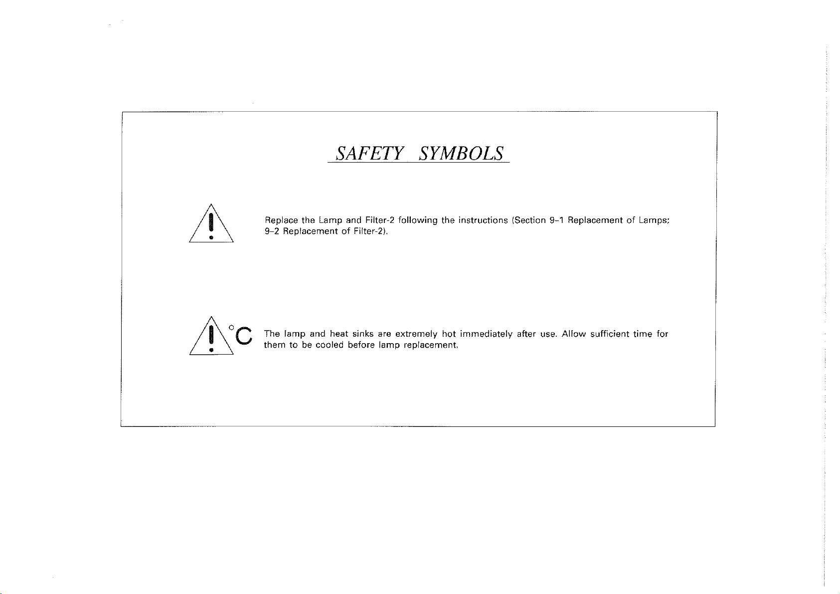
SAFETY
SYMBOLS
Replace
9-2
The lamp and heat
themtobe cooled before
the
Lamp and Filter-2
ReplacementofFilter-2l.
sinks
following
are extremely hot immediately after
lamp
replacement.
the
instructions
(Section 9-1 ReplacementofLamps;
use.
Allow sufficient time for
Page 5

CONTENTS
1 FEATURES AND MAIN SPECIFICATIONS 1
1-1 Features 1
1-2
1-3
Main Specifications 2
Safety Precaution 4
2 DESCRIPTION OF CONTROLS 6
3 CONSTRUCTION 9
4 STANDARD SET 10
5 PREPARATION
5-1 Installationofthe
5-2
5-3
5-4
5-5
5-6
5-7
ConnectiontoAC Mains Supply..................................................................................
Preparationofthe
Preparation
Connecting
Preparation
Preparation
6 INSPECTION
7 OPERATING
7-1 Use in
7-2
7-3
7-4
7-5
8
CARE
8-1 Care after Use 28
8-2
With
With
Cinematography
After
AND STORAGE 28
Storage 28
FOR
USE
Light Source
Videoscope 13
for
Air
Feeding/Water Feeding and Suction 13
the
Endoscope to
for
Still Photography................................................................................ 15
for
Cinematography, CCTV and Polaroid Photography........................ 15
OF
ENDOSCOPIC SYSTEM 16
THE
LIGHT
Combination
Fiberscope 25
Rigid Scopes 26
Use
SOURCE
with
and CCTV
the
Light
Source 14
the
Videoscope 24
27
27
11
11
12
24
1
2
3
4
5
6
7
8
9 MAINTENANCE 29
of
9-1 Replacement
9-2
9-3
9-4
9-5
ReplacementofFilter·2
Resetting
Cleaning
Periodic Inspection 32
Lamps 29
the
Circuit Breaker
the
Ventilation Grills
31
31
32
10 TROUBLESHOOTING GUIDE 33
11
ENDOSCOPIC SYSTEM CHART (EVIS/OES SYSTEMS) 35
11-1
11-2
OES
System
EVIS Endoscopic Video
Chart 35
Information
System
37
9
10
11
Page 6

(j)
z
o
~
U
L.1.
U
UJ
0-
(j)
Z
;:;:
2'
o
z
<t
(j)
UJ
a::
::::>
f-
<t
UJ
L.1.
1
1.Byuseofthe mode selector, the instrument servesasa possible and universal light source
EVIS
for OES-fiberscopes, Olympus rigid scopes for
color chip
2.ByuseofOES
scope point
3 When using
canbereleased.
4.
Combined
advantages
• Photographs under stable exposure
• Date is visible
• Remote shutter release using a foot switch frees the endoscopist from finger-tip shutter
operation.
• Indicatorsinthe camera's viewfinder predict exposure level before taking photographs and
the exposure level
5.
1.5 times the flash outputofthe maximum illumination intensityofthe light source
available.
6.
Flat switches and display panel
7.Anemergency lamp turnsoninstantly if the Xenon lamp burns out, to provide illumination
bright enough for endoscope withdrawal. A light
the emergency lamp
instead of the Xenon lamp.
system), and for
system,
canbechecked by the transillumination function.
EVIS
100 or
with
OES
canbeoffered.
in
the viewfinder and imprintedonfilm.
is
EVIS
200 System (sequencing system).
EVIS
100 system and
EVIS
200 system, by use of the Foot Switch, the anc'illary equipments
fiberscope, SC16-10 and rigid scope and SC16-10R, the following
can
be takeninshort distances.
given when taking photographs.
can
be easily wiped clean.
is
not installed,isinstalled improperly orisburned out, orislighting
100 System (instantaneous single-plate
EVIS
200 system, the insertion position of the
on
the front panel indicates at a glance if
is
8.
Air feeding pressure
9.
With no scope and even when Xenon lamp illuminates, illumination light automatically dims
to prevent dazzling and the air feeding pump simultaneously stops.
10. Combined
functionated.
with
can
be adjustedinthree levels.
function expansion devices (under development), light source
canbemore
Page 7
]-2
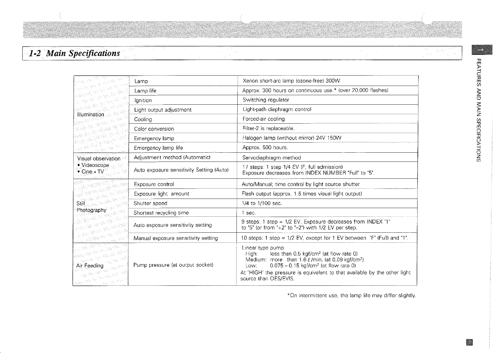
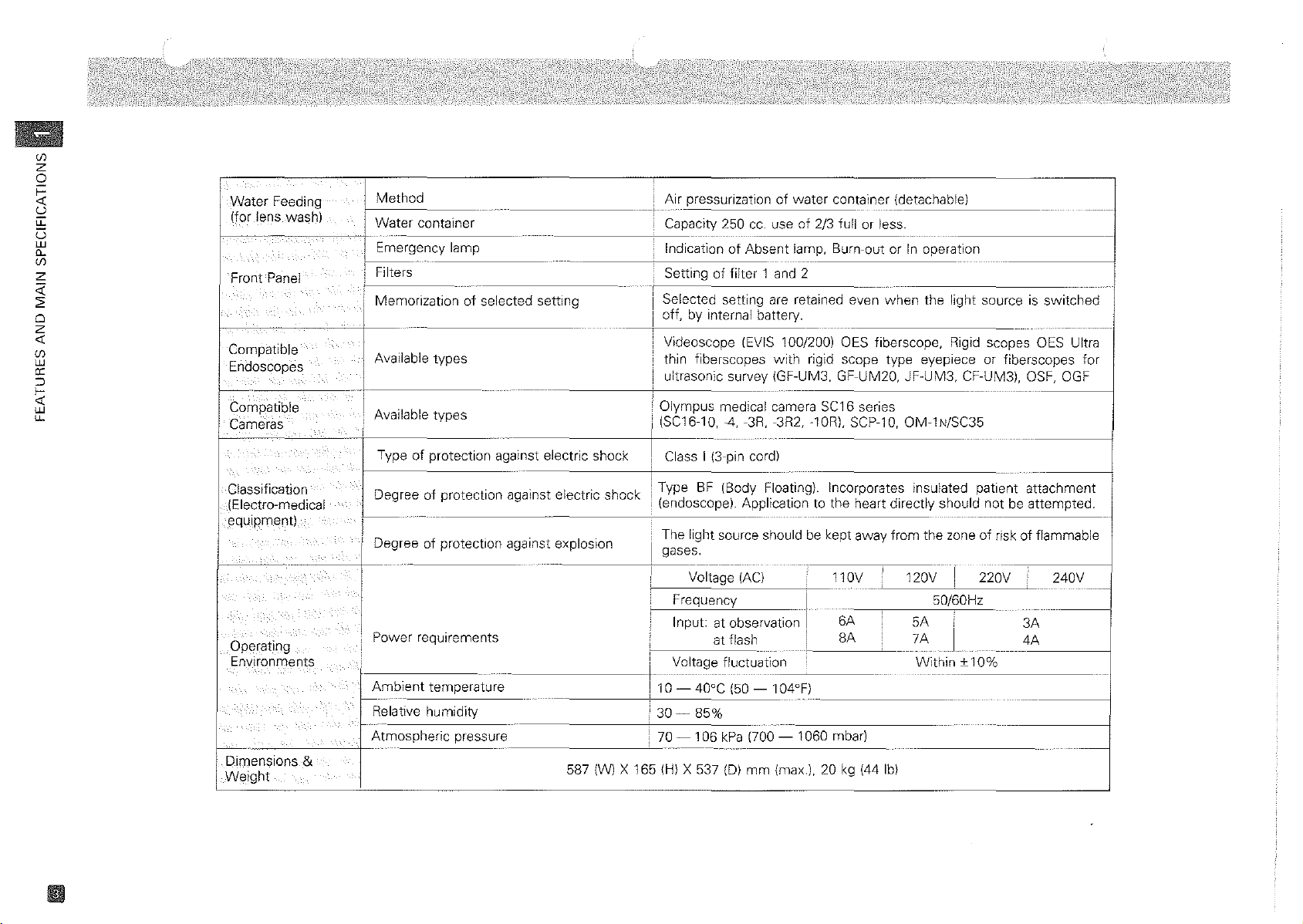
Main Specifications
Illumination
Visual.-observatjon
•Videoscope
• Cine-
Still
Photography
TV
F~edlng
Lamp
l-------
Lamp life
Ignition
' Light output adjustment
1-----"--
Cooling
Color
conversion
Emergency lamp
I
Emergency lamp life
-
-
-~~
Adjustment method (Automatic)
Auto exposure sensitivity Setting (Auto)
Exposure
--
Exposure light
control
amount
Shutter speed
Shortest recycling time
Auto
exposure
Manual exposure sensitivity setting
Pump pressure
sensitivity
(at
output socketl
setting
_._---~~
m
"
~
C
!
Xenon short-arc lamp (ozone-free) 300W
I
Approx. 300 hours on continuous
!
LSwitching
Light-path diaphragm control
I
Forced-air
Filter-2isreplaceable.
Halogen lamp (without mirror) 24V 150W
-
-
Approx. 500 hours.
--
regu~at_or
cooling
use'
(over 20,000 flashes)
-----
--------------
-----
----
----
---------
Servodiaphragm method
17
steps: 1 step 1/4EV(F;
I
I
,
Exposure decreases from INDEX NUMBER
I
Auto/Manual; time controlbylight source shutter
Flash
output (approx. 1.5 times visual light output)
1/4
to 1/100 sec.
1
sec.
i
_.
9 steps: 1 step
to
"5"
(or
10 steps: 1 step
~
1/2
from "+2" to "-2") with
~
112
full admission)
"Full"to"5".
---_._--
-
----------------
EV.
Exposure decreases from INDEX
1/2
EV
per step.
EV,
except for 1EVbetween
-------
"F"
(Fulll
---
-----------------------
-------
"1"
----
-----------
and"1".
--------
----
:0
m
(j)
::>
z
o
S
~
z
(j)
-0
m
Q
"
(i
~
o
z
(j)
Linear type pump
High: less than 0.5
Medium: more than 1.6 £Imin. (at 0.09 kgf/cm
Low:
At
"HIGH"
source than OES/EVIS.
i
0.075 - 0.15 kgf/cm'
the pressureisequivalent to that avai!able by the other light
kgflcm'
(at
(at
flow
flow
rate
rate
0)
2
)
0)
*On intermittent
use,
the lamp life may differ slightly.
Page 8
(f)
z
o
~
'd
li-
e;
W
0-
(f)
z
<i'
~
o
z
-0:
(f)
w
0:
o
~
W
li-
Water
Feeding
(for lens wash)
Front
Panel
Compatible
Endoscopes
e-----
Compatible
Cameras
Classification
(Electro-medical
equipment)
!0!:!<I~'
6
f····
peralng
Environments '
Dimensions &
W~ight
..
Method
Water
container
Emergency lamp
j------
Filters
!
,
Memorizationofselected
i
types
types
of
protection against electric shock
of
protection against electric
-
i
I
!
L--
Available
Available
Type
Degree
I
"'
oW",""
:
Power
I
-
requirements
Ambient
Relative humidity
Atmospheric
temperature
pressure 70 - 106
Air pressurizationofwater
_____
L..
.•
250
Capacity
Indication
Settingoffilter
setting
-------
shock
'~"~""""'""
Selected setting
off, by internal battery.
Videoscope
thin fiberscopes
ultrasonic survey (GF-UM3, GF-UM20, JF-UM3, CF-UM3), OSF, OGF
'
Olympus
~C1610,4,3R,3R2,
! Class I (3-pin cord)
BF
IType
(endoscope). Applicationtothe
The light source should be kept away
gases.
Voltage
Frequency I
I
nput:
i
Voltage fluctuation
cc. useof2/3 fullorless.
of
Absent
1
and 2
are
(EVIS 100/200)
with
medical camera
(Body Floating).
(AC)
at
observation
at
flash
container (detachable)
lamp,
Burn-out
retained even when the light sourceisswitched
OES fiberscope, Rigid
rigid scope
5C16
lOR!, SCP-10, OM-1 N/SC35
Incorporates insulated
110V 120V I 220V 240V
6A
!
6A
or
In operation
type eyepiece
series
heart directly should
from
the
!
50/60Hz
5A
7A
Within
I
10 - 40°C (50 - 104°F)
I
i
30-
85%
kPa
,.~-----,-"
587 (W) X 165 {HI X 537 {DI
(700 - 1060 mbar)
mm
{max.!, 20 kg (44 Ibl
--
scopes
or
patient
notbeattempted.
------
zoneofriskofflammable
I
±10%
--
OES Ultra
fiberscopes
attachment
3A
4A
---
---
for
-----
Page 9
l_l_-3_S_a--'-rfi_
Be
suretoconnect
toahospital
mains
Powe'
e
_ty_P--'-_re_c_a_u_tio_n_s
the
grade
outlet).
receptacle(awall
~
~\,
1\
,
"
PIU:~~
Hospital
receptacle
(wall
power
mains
plug
grade
outlet)
-----)::===========
CD
The CLV-U20 light source should be used onlyina medical facility
trained physician.
@ The light source is designed (floating)tofunction
(endoscopes)toprevent operator/patient shock. Endoscopes and camerastobe used
should
not
be groundedinordertoprevent
from other electrical apparatus appliedtothe
gloves as an added precaution.
® The housing of the light source must
the
line cord ground connection.
@)
The light source/endoscope combination should never be appliedtothe
@ Never install and operate the light source where there
@ Keep liquids away from
damage. Do
not
use
all
electrical equipmenttoprevent operator shock and instrument
the
light source if spilled fluids have entered
be
integrally
shocks
patient
grounded securely and effectively. Do not defect
with
which
may
The endoscopist should wear rubber
is
the riskofflammable gases.
under
the
supervisionofa
insulated patient
be causedbyleakage
heart directly.
the
unit.
attachement
with
current
."
m
~
C
:u
m
CIJ
»
it
z
o
;;:
:J:':
z
CIJ
-0
m
n
Jl
n
~
o
z
CIJ
Flam",a',le gases
Spillable
liquids
Page 10
(f)
z
o
i=
«
u
u:
U
LlJ
0-
(f)
Z
;;:
2'
Cl
z
«
(f)
LlJ
a:
:::>
f-
«
LlJ
CL
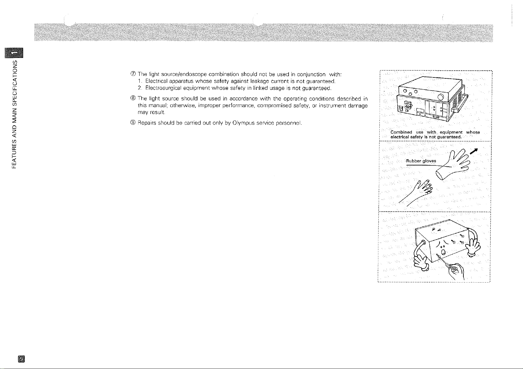
(j) The light source/endoscope combination should not
1.
Electrical apparatus whose safety against leakage currentisnot guaranteed.
2.
Electrosurgical equipment whose safetyinlinked usage is not guaranteed.
® The light source should
this manual; otherwise, improper performance, compromised safety, or instrument damage
may result.
be
usedinaccordance
be
used in conjunction with:
with
the operating conditions described
® Repairs should be carried out only by Olympus service personnel.
,._----------.---.----------
in
Cpmbinedusewith
electrical
:
.,,
.... -
safetyisnot
._._••c.__• ,_,•••.•.••••
Rubber
gloves
..
_.....
_----------------------.---,
equipment
guaranteed.
~
whose
.__._, .:
:.
~
----,----_._------
---
-.
-_._---
..
,
...
-
.~------------------_.
----
...
:
Page 11

2
FRONTPA~
Mode
Selector
Press one of the push-buttons
indicating system names to
select one system.
Output
Transmits light, electrical
signals and air through the
endoscope.
Power Switch
Press the upper portionofthe
power switch to turnonpower
source
indicator
and
turns
Lamp
Press to turn on Xenon lamp.
Connector
r-----+---W'\--------I%:\--\--+f------4--....
OLYMPUS
@@CLV-U20
POWER
~
ON
the
power
on simultaneously.
Ignition
switch
Switch
AUTO/MANUAL
Press to set AUTO or
for stili photographs Including
polaroid.
Air
Press to adjust
flow
IGNITION
Connector
Scope's
Connects
cord for SC35 and SC16-10R.
Footswith
Connects
MB-332.
for
Rigid
Camera Cord
with
the camera
Connector
withafoot
release
Regulator
pressure.
AUX
Exposure
Press to set exposure
sensitivity.
Exposure
Selector
MANUAL
air-
";\-'TI~R_
1
11
FOOT
Lamp
Life
Indicates
hours {approx.)
AUTO/MANUAL
Press
brightness.
* For
*
to
other
"MANUAL"
TV,
avoid
thermal
weI! as
the
also
level.
With
EVIS 100/EVIS 200
selector
"AUTO".
Sensitivity
ILL
INEXADJUS
F
Ll<::l
10+2
SW.
Meter
cumulative
of
Brightness
set
"AUTO/MANUAL"
combinations
should
mucosal
to
protect
minimum
is
automatically
Selector
PHOTO
working
Xenon lamp.
Selector
than
be selected
damage
your
eyes. Select
necessary
Systems,
CINE/
set
of
to
as
light
the
to
Filter
Switch
Each
presstoselect "filter-1","filter-2" and
"non".
With a special-purpose filter {optional) for
visual observation and photography, press
"filter-2" to give the illumination of "filter-
2".
* "fllter-2"
cutting
be replaced
filteronrequest.
*
With
cannot
Press
to
"AUTO")
"MANUAL)
Is
attached
filter
{when
withaspecial-purpose
EVIS 200
be used.
Transillumination
Press to turn 0 N the transillumination indicator.
The light from the endoscope
becomes
seconds and automatically
return.
*
With
the
itor
blackorwhite.
* The
to
the
ly
switch
transillumination.
Brightness
set
CINEnv
or
to
adjust light level (at
with
Installed) and can
System,
brighter
EVIS 200
imagesonthe
get
over-exposed
illumination
original
after
pressing
again
exposure level
a
"filter-1"
Switch
system,
returns
level
while
Control
light
for
mon-
short-
the
using
(at
o
m
CJ1
()
:rJ
~
o
z
o
-n
()
o
Z
-i
:rJ
o
r
CJ1
9
in
Page 12
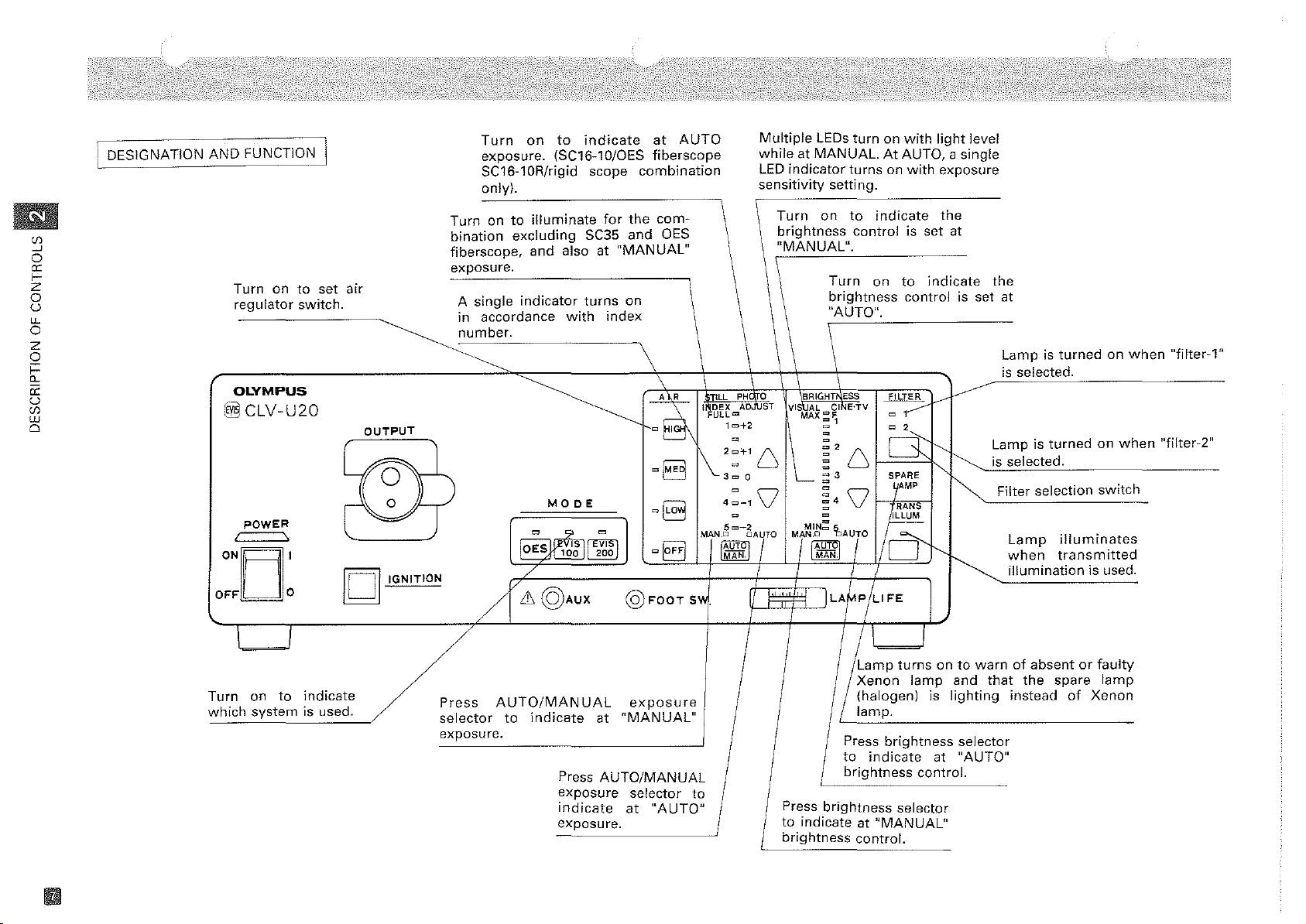
I DESIGNATION
AND
FUNCTIOt<j
Turn
on
to
indicate
exposure. (SC16-10/0ES
SC16-10R/rigid scope
only).
at
AUTO
fiberscope
combination
Multiple
whileatMANUAL.AtAUTO, a single
LED
sensitivity
LEDs
indicator
setting.
turnonwith
turnsonwith
light
level
exposure
on
Turnonto
(/)
--.J
o
a:
I-
Z
o
u
"-
o
z
o
Turn
ontoset
regulator
air
switch.
t
a:
u
(/)
UJ
o
OLYMPUS
~
pOwER
==--"
ONEJ'
OFF
CLV-U20
0
OUTPUT
~
II
II
IGNITION
bination
fiberscope,
exposure.
A
single
accordance
in
number.
~
illuminate
excluding
and
indicator
SC35 and
also at
turns
with
for
the
"MANUAL"
on
index
com-
OES
\
~~~
oB
MODE
~IE~g)
/
6@AUX
00
cB
@FOOT
TILL
I~Bt~=A
1=+2
1\2:T1
300
':-1
5""-2
MAN.D
[AUTO)
MAN
SY.
Turn
brightness
"MANUAL".
\\
PH
0
BRIGHT
VISHf-L
-NST
c
c
,DAlTO
I I I
MAX~~
U
L-
\J
r
~
to
control is
Turn
brightness
"AUTO".
\
ESS
c;INE'TV
~2
U
~
3
c MP
0\J
Cl
~.
MIN~
o
~Ar
AUT
[
9 0
MAN.
!LAf,!P!L1FE
indicate
on
f!~l---
o1
o~
U
S~RE
ILLUM
~
set
indicate
to
control is
~
~
t'---
the
at
J.------
~
~
~
the
set
at
Lampisturnedonwhen
is
selected.
Lampisturnedonwhen
is selected.
Filter selection
Lamp
when
illumination
switch
illuminates
transmitted
is used.
"fi1ter-1"
"filter-2"
/
1
\
Lamp
Xenon
(halogen)
lamp.
brightness
Press
to
indicate
brightness
"MANUAL"
control.
turnsonto
selector
lamp
is
at
control.
and
lighting
warnofabsentorfaulty
that
the
spare
instead
selector
"AUTO"
of
lamp
Xenon
Turn
which
\
on
system
I
to
indicate
is used.
~.
selector
exposure.
"WIM"""
to
indicate
Press
exposure
indicate
exposure.
exposure
"MANUAL"
at
AUTO/MANUAL
selector
at
"AUTO"
I
I
to
Press
brightness
to
indicate at
brightness
Page 13
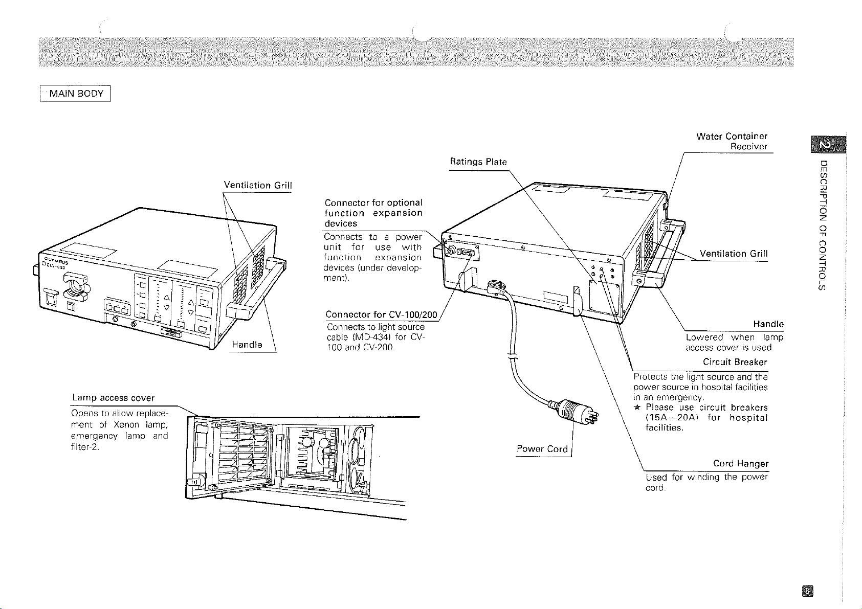
MAIN
BODY I
Ventilation
Grill
Connector
function
devices
for
optional
expansion
Connects to a power
unit
for
use
with
function
devices (under
ment).
expansion
develop~
Ratings Plate
Water Container
Receiver
o
m
(f)
n
:IJ
::'1
6
z
o
-n
•
Ventilation
Grill
n
o
z
..,
:IJ
o
r
(f)
Lamp
access
Opens to allow replace-
ment
of Xenon lamp,
emergency
filter-2.
cover
lamp and
Connector
Connects
cable (MD-434) for
100 and CV-200.
for
CV-100/200
to
light source
CV-
Power Cord
Handle
Lowered
access coverisused.
Protects the light source and the
power source
inanemergency.
* Please use
(15A~20A)
facilities.
Used for winding the
cord.
in
circuit
when
Circuit
hospital facilities
Breaker
breakers
for
hospital
Cord Hanger
power
lamp
Page 14

3
z
o
f=
u
::>
ex:
I-
(J)
Z
o
u
CCD
EVIS
100/200
Videoscope
lEVIS
100/200 SYSTEM I
Videoscope
Cable 100/200
Photodocumentation
Equipment
I
OES
•
System I
Output Connector
•
r---"
I
I
I
I
I
I
I
I
I
I
I
I
I
I
I
I
I
I
-~
R.G.B.
Motor
Panel displaY
switch
Syslem
Filter
rYnt;jr---l~~-
Diagram
Filter
for
Xenon lamp
Light Source
'::==1--
~-"-;'=_
EVIS Video System Center
1-----
DC
supply
Xenon I
power
supply
power
Power
switch
t==='~
Power Plug
...---
Connection (optional)
....---Connector
Light source cable
.---
IMD-434)
for
CV-lOO/200
Keyboard
CV
-1
OO/CV
-200
Power Plug
F=:::::\'\;:::::==~
Isolation
Transformer
Page 15

4
CD
Main Body
(including Xenon lamp
ClJ
Water Container
(CLV~U201
.
and
(MD~431
I.
emergency lampl
@ Vinyl Dust Cover (MD-4481 .
@ Foot Holder (MD-5121 .
1set
CD
==~
/
Do not handle rolighly.
Place for
at any time.
easy
use
(fJ
-1
J>
Z
o
J>
:0
o
(fJ
m
-1
* Store the instruction manual
in
the vinyl bag and retain for easy
use
at any time.
Page 16

5
..
LlJ
(J)
:::>
a::
o
u.
Z
o
~
a::
:;:
LlJ
a::
"-
Refer alsotothe instruction manuals supplied
r-=--:---:--:--:--:---~:c--c::---c-~-c::---------------------------,
!5-1 Installation
D
Please
manual
refertoeach
for
products.
instruction
of
the Light Source
CD
Ensure the safety precautionsin1-3, page 4
@ Place the light source on a stable surface
*
Ventilation
*
Ensure
* Do
* Please
settingtoTC-Vl
*
When
processor.
@ Always
surface orincase the light source moves whileinuse.
0
must
notbeblocked.
the
stabilityofthe
not
use
the
side
refer
alsotothe
(Compact
combined
set
the light source using
with
cart
handleofthe
instruction
Video
CV-l00/200
the
when
light
Trolleyl.
and
attached
with
the endoscope and photographic attachments.
are
met.
in
a horizontal position.
the
light
source
manuals
always
foot
sourceisplaced
as a
foot
for
TC-Vl,
set
the
light
holder (MD-5l21
support.
CV-l00
source
when
on
it
.
and
CV-200
below
placed on sliding
the
when
video
{Preventionofoverheating]
Ventilation
must
Place
the
on
astable
notbeblocked.
light
base.
source
i
Use
the
foot
placementofthe
holders
light
for
stable
source.
place
the
light
a horizontal position.
source
in
Page 17

1_5_-_2_C_o_n_n_ec_ti_·o_n_f_o_A_e
C__.
M_az_·n_s_eS_eu_'P_'P_ly
CD
Make sure the
power
~
switchisin
the
off
~):===========
position.
Power
switch
position.
Always
properly
GRADE" receptacle or the
mains
Power
shouldbein
connect
the
to
outlet.
~-J®
plug
Hospital
{wall
[Shock
power
the
"HOSPITAL
Ratings
grade
mains
prevention]
the
receptacle
outlet)
"OFF"
cord
wall
plate
~
@ Connect the power cord properly
outlet that meets the input requirements indicated on the ratings plate on the rear panel
the light source.
@ The power-cord plug
outlet
13-cord
* Do
not
use
safety
precautions.
*
Connect
without
*
Firmly
bending,
*
When
of
subsequent
hospital
the
connectingtotable
set
pulling,
combined
light
sourcetothe
grade
* Refer also
mustbeconnected to a grounded hospital grade outlet or a wall
outletl.
converter
light
power
power
receptacle.
to
the
adapter
source
cord
during
twisting
with
TC-V1
secondary
voltage
instruction
to
the "HOSPITAL GRADE" receptacle or the wall mains
from
three
pin
power
directlytohospital
tap
for
safety.
inspection.Donot
and
pressing.
(compact
lowering.
manuals
video
outletofTC-V1toprevent
Be
suretoconnect
for
combined
plugtotwo
grade
receptableorwall
apply
excess
trolley),donot
the
instruments
pin
forcetopower
connect
malfunction
power
being
power
mains
the
cord
used.
power
duetothe
directly
plug
outlet
cord
of
rna-Ins
for
by
cord
to
The
to
and
converter
two
pin plug
electrical
adapter
from
cannotbesafely
shock
three
pin plug
grounded
may
v
m
"
~
"
:to;
is
z
"o
"
c
en
m
Do
not
connect
sourcetothe
the
outlet
power
for TC-V1.
cord
for
the
light
Page 18

5-3 Preparation
of
the Videoscope
w
(f)
::J
a:
o
CL
z
o
~
a:
<>:
0-
w
a:
0-
Select
EVI~
100orEVIS 200.
I'"
!,i;g~I_~'"
',8'
-":"'.
J~IJ~IJ,~~
1§]~['J:lJ1
I
In
I!
I
III~
J~
5-4
2/3
T
-L
Water
-8i
@.QQT'W.
.:g;"o'
CV-100(200
~CV-100/200connecto~
Light
"""
Light
source
Preparati,Qn
feed
tube
:"'~r,,:~'i.!~
,-"
I "
I"
"'"
-1-"",l:J
'
"""
J""">e'
I
'---J
source
connE!c~,or
=
rnU
c~
forAir
Refertothe
System Center ICV-l00/CV-2001
CD
Prepare the
Videoscope, Compact Video Trolley, and
@ Ensure that the
option) between the
100/200' connector on the back of the light source.
@ Use the mode
When using the
When using the
When
EVIS 100or200 is selected,
*
Feeding/Water Feeding
CD
When
water
Tighten the
*
Change
* Use
*
Ifapoor
wipeitcompletely
CV
Connect the feed tube of the
@ If suction
connector.
*Check
*:
Use
cap
the
only
is
the
only
instruction manuals of
EVIS
Video System following the instructions foundInthe manualsofthe
power
switchis'OFF' and then connect the light source cable
'light source' connector on the back of the CV-100/200, and the 'CV-
switch
and select the
EVIS
100, select
EVIS
200, select
feedingisneeded, fill the container approximately 2/3 full
securely
water
clean
connection
needed, connect the tube from the suction
suction
electrically
and
daily,
water
(distilledorsterile)toprevent
with
dry
withasoft
pump
insulated
the
Vjdeoscope, Compace Video Trolley, and
in
use.
EVIS
Video System Center CV-l00/CV-200,
EVIS
Video Systemtobe
~.
~.
photo
sensitivity
and
Suction
then hand
the
water
carefully
the
containeronthe container receiver.
scope
has caused
cloth,
etc.
containertothe connector on the scope.
for
leakage
suction
tube.
will
cloggingofthe
watertospill
pump
and
electrical safety.
used:
not
be indicated,
with
with
onto
the scope suction
clean water,
water
the
equipment,
EVIS
Video
IMD-434)
channel.
EVIS
I
Suction
tube
Page 19

5-5 Connecting the Endoscope to the Light Source
II
Vide,osCO!lle Cc,nne[:tion
CD
Turn
OFF
the light source.
(2)
Turn
OFF
the
EVIS
Video System Center ICV-l00/2001.
@ Push the scope into the scope socket until a click
Videoscope cable
@ Attach the videoscope cable
1.
Align the dotsonthe cable and the scope, and push together firmly.
2.
Rotate the ring of the videoscope cable while pushing the cable
is
until a click
*
Be
sure
attachingorremoving
left
'ON'
* To avoid
connector.
CD
Securely connect the scope into the scope socket until a clickisfelt.
felt.
that
the
power
during
damagetothe
attachment.
to
the electical connector.
switchofthe
the
videoscope
ceo,
do
not
EVIS
Video
cable. The
touch
is
the
felt.
System
CCO
electrical
and
the scope together
Center
maybedestroyedifpower
contacts
remains
inside
'OFF'
the
when
electrical
:D
"
m
~
is
Do
not
cable
with
attachordetach
power
ON.
the
videoscope
:D
~
o
z
"o
:D
C
(f)
m
[ConnectionofvideoscopeJ
[Connectionoffiberscope]
I
~~~&~~~
CD
Securely connect the scope into the scope socket until a clickisfelt.
II
Connection
CD
Securely connect the light guide of the rigid scope into the scope socket.
or' fiberscope lfor ultrasonil:.
surVE
Page 20

I 5-6 Preparation
for
Still Photography
w
(J)
::J
0:
o
"-
z
o
~
0:
«
Il.
w
0:
Il.
Camera
15-7
cord
[Camera
cord
connection]
Preparation
Refer also to
be
used
CD
Refer to the following table.
Endoscope
f--
Fiberscope
Rigid
CD
For rigid scope, camera cord (EC-26, 27 or 28)
light source.
of
(2)
Foot releaseisplugged into the connector for foot release
* This
rigid
for
Cinematography, ccrv
the
with
the light source.
I--
SC16-3R
SC16-RR2
f
applicationisonly
scope/SC16-10R.
instruction manuals for endoscopes and photodocumentation equipment to
Camera
SC16-10
SC16-4
N
SC35
SC16-lOR
OM-1N
SC35
X •
FP
!
possible
and
contact I
-
Shutter speed
-
- No. 1604-0
X
-
X
X
1/4 sec.
-
-
1/4 sec.
I
:
is
plugged into rigid scope's camera connector
when
for
the
combinationofOES fiberscope/SC16-10 and
l'olaroid® Photography
Film Filter
No. 1610-0
Ektachrom
(ISO/ASA 200)
1610-0
No.
No. 1604-0
Ektachrom
IISO/ASA 400)
necessary.
!
IS not lighted.)
switch
OFF
(Filter-1/2
indicator
Refer alsotothe instruction manuals for endoscopes, photography devices and
with
system (OTV-F2/S2) to be used
CD
For cinematography, refer to the endoscope instruction manual.
(2)
For cinematography, prepare cine camera
daylight type film (lSO/ASA 160).
® For
CCTV,
refer to the
@ For polaroid® photography, refer to the instruction manuals for photography instruments.
is
SCP-lO film
a high speed color film
OESTVSystem instruction manual.
the light source.
with
a C-mount adapter (e.g. Baulieu 16R) and
(TYPE
779 ISO/ASA 640).
OES
TV
Page 21

6
Before each operation, the equipment should be inspected according to the following
the
procedure. Should
equipment; contact the Olympus service center.
slightest irregularity or abnormality be suspected, do not use the
O~YM"U5
OCLV_U'O
Power
switch
[Connectiontopower
[Inspectionoflamp-life
Ol.VMf'VS
r"'CLV-U20
Ilgnition
of
Xenon
[Lightingoflamp]
Endoscope
distal end
supply]
meter]
I~~~
i
@.ux
lamp
D
Turn ON the power switch: The power indicator and
the
Iront
panel light up and the cooling Ian willbeheard.
*
If
the
light
source
access
the
II
Igniting
CD
Make sure the pointerinthe lamp life meter is positionedinthe green zone.
*
If
to
@ Press the Lamp Ignition
the endoscope.
*
If
along
turn
failstoignite,
*
If
Troubleshooting
cover
light
source
the
the
pointer
9-1
Replacement01Lamps,
the
Xenon
with
the
off
the
power
the
emergency
does
not
is closed
I
has reached
lamp
emergency
replace
tightly.
accordihgto9-3
;,,~.~
switch
failstoignite,
switch
Guide, page 32.
and
the
lamp
show
any
signofbeing
Then
inspect
Resetting
the
red zone, replace
page 28.
and make sure the illumination lightistransmitted through
the
emergency
lamp
indicator
repeat Steps
lamp
withanew
indicator
is
LED
the
the
Circuit
(red)onthe
IIJ
and B above.
one.
lighted,
(Light-Emitting Diode) indicators
activated, make
circuit
breakeronthe
Breaker, page 30.
the
lamp
withanew
lamp
will
automatically
front
replace lamp(s)
on
sure
the
lamp
rear panel
one
according
turn
on,
panel. In such a case,
lithe
Xenon
referring
lamp
still
to
10
{~~mJuwlamp~~ro~n.J
of
Lamp
access
cover
Lamp
access
cover
{Caution
be.closed
when
spare
Xenon
tightly,
lampisdefective.
lamp
should
is on.)
Xenon
lamp
indicator
z
i
(f)
m
"
':1
6
z
o
"
m
Z
o
o
(f)
(")
o
"
n
(f)
-<
(f)
-4
m
'5:
/
Illumination
(~ht
Page 22

Ell
:;e
Ll.J
f0-
Ul
>-
Ul
u
0:
o
u
Ul
o
o
Z
Ll.J
LL
o
Z
o
B
Ll.J
CL
Ul
Z
Inspectionofturning
and
off
alternatively
lAdjustmentofoutput
on
intensity]
D
InsJlecti<1O
CD
EVIS
100/200 Systemisautomatically set to "AUTO". Check the
indicators being lit.
@ For
OES
System, press the AUTO/MANUAL Brightness Selector.Ateach pressing, a peep
is
sounds and AUTO/MANUAL
and the Illumination Light at MANUAL being illuminated and then
* If
the
CINE
·TV
switch
Brightness
Q)
Press the Brightness Control switch
light goes
Keep the switch depressed: the peep sounds continuously, and the LED light goes up
(down) sequentially
* Once
any
further
*
If
the
above,
Selector
up
(downl one step
"MAX"
change.
endoscopeisdisconnected,
but
the
can
with
("MIN") has been reached, pressing
actual
switched alternately. Check the
is pressed
function
with
increasing (decreasing) light output until "MAX" ("MIN")isreached.
output
without
and
,,,,,
increased (decreasedl illumination light output.
the
brightness
connectingtoTV camera,
the
illumination
Ii",).
At
each pressing, a peep sounds and the LED
the
switch
LED
indicator
remains
at a
light
low
CINE.TVand the AUTO
CINE.TVindicator at AUTO
is
set to MANUAL.
AUTO/MANUAL
light
output
will
level
maybeminimized.
) dose
still
changeasdescribed
until
the
endoscope
not
connected.
* The
CD
Dip the fiberscope distal endinclean water.
(2)
Press the air Regulator switch: A peep sounds, and the LED indicators turnonsequentially.
Air
occluded, or by pump noise) varies
* The air
Q)
Set the pressure level to "HIGH" by pressing the switch. Make sure the waterisemitted
through the distal end nozzle.
switch
damage
flow
rate (identifiable by bubble amounts when the air/water valveonthe fiberscope
the
pump
should
rubber
does
not
be pressed
covering.
not
operate
with
each setting.
when
withapointed
the
endoscope
or
hard
object
is disconnected.
since
this
cause
will
Do
not
push
the
button
is
is
object.
with an
edged
[Adjustmentofair
feeding
pressure)
Page 23

EVIS
Video
System
CD
Connect the videoscope and the
instruction manuals.
Q)
Use the mode selector to select the
@ The light control will display 'AUTO' automatically.
@)
Testtosee if the light coming from the light guide fiber at the distal end of the scope
in
becomes stronger,
check to see that the light from the fiber varies
1 and 5 {with the distance
relation to the distance between the scope and a viewed object. Also
to
EVIS
Video System Center by following their respective
EVIS
Video System to be used with.
when
the CINEfTV valueisadjusted between
the viewed object held constant}.
Increase
gradually.
the
distance
OES
System
~~
yv'b
[Mounting
Check
illuminated
the
the
i
v
camera]
indicator
alternately.
being
CD
Connect the videoscope and turnonthe lamp.
Q)
Press the Transilliumination Switch, and confirm that the light becomes brighter, and then
to
returns
*
With
*
When
to
CD
Attachanunloaded camera to the scope eyepiece by following the instruction
scope and camera.
@ Test the operation of the
set it to 'AUTO'.
*
When
10R
the
the original leve! approximately nine seconds later.
EVIS 200 system,
pressing the
the
origianl
the
camera
mode
level.
mode
viewfinder,
switch
monitor
Transillumination
~
exposure control switch(a'peep' should be heard), and then
switchisset
and
photography
must
be set
images
Switch
to
1~6~1
or
to~.
will
~
become
will
over-exposed in black and
under
transillumination,
, a
flashing
be impossible.
will
be seen in
When
using a camera,
the
light
the
with
SC16-101
white.
returns
the
~
[Inspectionofthe
[Transmitted
illumination]
5-60mm
brightness!
The
illumination
gets
brighter
automatically
and
reset.
light
is
z
(fJ
m
"
g
o
z
o
"
m
Z
o
o
(fJ
CO
o
"
n
(fJ
-<
(fJ
-4
m
;;;:
Page 24

Ell
2:
LU
fUl
>-
Ul
u
0::
o
u
Ul
o
o
Z
LU
u..
o
z
o
E;
LU
"-
Ul
Z
Illuminated
:~~~i;r::£
"..,
":
§j~~l
@,.,
Auto
(5C16-10 +
Auto
(a
camera
or
non
jO,:
:~
-~.."'~'""
@",m.
exposure
QES
Illuminated
exposure
other
DES
scope)
Illuminated
Manual
17
1
fiberscope)
than
5C16-10 + DES
exposure
I:
\7-;;
J~
~
@ Selection
combinations listed in the following table.
OES
--
of
the photo sensitivityismade
Endoscope
Rigid
scope
Camera
0 SC16-10
SC16-lOR
SC16-4
SCP-l0
OM-1N
SC35
SC16-3R
SC16-3R2
OM-1N
SC35
not
mountedonthe
fiberscope
the
ADJUST
turn
the
individual
-
e-
*
When
turn
*
With
momentarily,
If
the
0
,
--
I
!
i
I
I
i
0
the
camera is
on.
the
SC16-10/0ES
the
"INDEX"
procedure, check
0
0
0
before
indicators
by
referringtothe endoscope and camera
I
I
Repeat pressing exposure
ADJUST
(Set the value desired: normally
*
*
A
U
T
0
Repeat pressing exposure sensitivity selector:
INDEX LEDs turn
(Set the value desired.)
*The
,
!
M
Repeat pressing exposure sensitivity selector:
A
!
INDEX LED2 turnonsequentially_
I
N
* F:=
U
A
L
endoscope,
combination:
indicators
on (insteadofthe
components
turn
Inspection (Setting)
(compensation)
Shortly
after pressing
sensitivity
normal
When
intensity becomes increased.
When
decreased.
the
For each step increaseofthe
ber,
ous step.
ADJUST
for
index
phenomenon.
setto"+" indices,
set to
smaller
amountofflash.
maximum
exposure
the
the
on:
this
correct
willbeilluminated.
"-"
indices, the intensity becomes
on
the
index
exposure
decreases 50%ofthe
"INDEX"
"INDEX"
is a
normal
indicators) in
connection.
sensitivity
LEDs turnonsequentially.
to
the
sequentially.
indicators
"0".)
selector,
the
number,
indicators
phenomenon.
the
the
exposure
This is a
exposure
the
index
always
turn
middle
selector:
light
greater
num-
previ-
on
of
Page 25

Illuminated
Settominimum
...}~~':J'TV
~
0
"6
j:\7
~
"'""'0
light
output
(j) Set the light level control switch
position (dark).
@ Place the distal end
switch release. The illumination should become strong for a moment, and then return
foot
the original state. A buzzer should also sound.
* Do
not
press the
exposure
* If
nothing
re-connect
and
may
result.
happens
them
of
the scope near to a suitable object, and press the camera shutter or
shutter
when
securely.
release
the
to
'MANUAL', and adjust the light level to the minimum
shutter
while
the
buzzer is
release is pressed, disconnect all
sounding,
as unevenorno
the
connections,
to
{Shutter
Do
is
release
not
activate
sounding
inhibition}
shutter
release
while
buzzer
[Settingofillumination
[Checkofthe
amountofflash]
ga
light]
5-60mm
CD
Verify that the lengthofthe intensificationofthe illumination
is
release
distances (between 5 and 60 mm) from the view object.
@ Ensure that the length of the light emitting time becomes shorter when the sensitivity
switch
*
If
and
occurs,
pressed varies
is
altered from +2 to-2(or 1to5).
using
combinations
the
SC16-10R,
turn
the
filter
with
the distance, by testing
other
than
the
images
switch
taken at
1 'ON'.
with
and the distanceisheld constant.
OES
fiberscopes and SC16-10, and rigid scopes
short
distances
when
the camera shutter
the distal end held at varying
may
be overexposed. If
this
z
(f)
'1J
m
(')
:::!
o
z
o
-n
m
Z
o
o
(f)
(')
o
'1J
n
(f)
-<
(f)
-l
m
;;
[Inspectionofauto
exposure]
Page 26

Set
exposure
"AUTO".
sensitivity selector at
@ If auto exposure
here.
is
desired, set the exposure control switchs to 'AUTO' and use the settings listed
2:
UJ
f-
(/)
>-
(/)
u
0::
o
u
(/)
o
o
z
UJ
LL
o
Z
o
E
UJ
CL
(/)
Z
Endoscop~
.
OESscop~
-I<
The OM-1N/SC35 settings refertouse
*The above
minus
side (sensitivity:
® If manual exposures
constant
[~~I-lt-y-P_~-
Rigid
Scop~
side (sensitivity: larger
as
needed.
..
_s~~:~~A~D~J_O-U_-S~T~~_C~~_IN_~_E_X_-,-_IND3_EX_*_-+_IN_~_EX
table
gives average values,
smaller
are
SC16-10
number).
number).
desired, set the exposure control switch to 'MANAL',
SC16-4!
with
the A10-M2 IOES scope) only.
butifthe
Underexposures
OM-1N/SC35-l
INDEX
3
pictures are
must
Camera
SC-P--1-0~~-S~C-16-10R[SC16-3~/3R2
If------'-----I
*OM-1N/SC35:
**SC16-3R/3R2:
overexposed,
be corrected on
and
set the sensitivity
ADJUST
I
S~t
S~t
correcttothe
o I
sync contact to X
sync contact to
the
plus
INDEX**
3
and
X.
1/4
s~c.
Page 27

Illuminated
[Settingofexposure
condition]
sensitivity
Change the distance.
.ry5-60mm
[Confirmationofexposure
level]
• Set ADJUST (compensation) display to
• Change the distance between the fiberscope's or the rigid scope's distal tip and a white
of
piece
changesasillustrated below.
paper. Make sure the display on the front panelaswellasin
o
Underexposure Slightly under
FAR
«~=============;:?>
Distance between endoscope's distal end
*
With
dark objectsorsmall-calibre
sometimes
failtoturn
* In case
willbeilluminated
*
Above
setting, and are
the
compensation
not
on.
the
compensation
displays
turn
on. Conversely, in a
value
with
camera's
represent
not
signal blinks in the camera's viewfinder),
only
applicable
"0"bypressing the Exposure Sensitivity Selector.
the camera's viewfinder
o
Correct
other
viewfinder.
the
exposure
when
Slightly over
and
(low
flash level) fiberscope, A
bright
endoscopy
than
"0", the
levels at
compensation
compensation
ADJUST
has been
Overexposure
NEAR
the object
room,Vindicator
signal (orange)
"0" (no
made
indicator
compensation)
(in
which
may
may
case
."
m
Q
o
z
o
-n
m
Z
o
o
(f)
n
o
Jl
n
(f)
-<
(f)
--1
m
'5:
z
(f)
Page 28

Cine
camera
CD
Mount the cine camera orTVcamera onto the endoscope eyepiece section.
(2)
Using the AUTO/MANUAL Brightness Selector, set the light source to AUTO: CINE.TV LEDs
turn on.
* On
MANUAL
automatically
mode,
the
light
respondingtothe
output
intensity
changsinthe
is kept
object
constant
distance.
and does
not
change
==:::!ILl;
[MountingofTV
~L=ame"
I~
camera]
I
2
•
w
f-
(j)
>-
(j)
U
a..
o
U
(j)
o
o
z
w
CL
o
z
o
B
w
a..
(j)
Z
ConnectionofCine
to
the
~
adapter
camera
@ Move the endoscope distal end away
distal end from the object, the stronger the light transmitted through the distal end becomes.
Next, keeping the object distance constant, change the exposure level sequentially from
to
"5":
the light Intensity should decrease.
* In
electrosurgery,
noise. For
taking
incorrect
photographs,
fom
the
object
exposure
may
sometimes
set several Cine and TV
Make sure that the farther away the
result
duetohigh
indicestotake
frequency
photographs.
"1"
Increase
the
distance
gradually.
~5_60mm
[Confirmationofbrightnessl
Page 29

7
This section outlines a genral procedure for endoscopy. The endoscopist should carefully
evaluate the clinical factors involved
and
decide the technical details of the procedure.
7-1
Read
use.
Use
the
zn
instruction
Combination with the Videoscope
D
manual before
Obs~lrvati(m
Set the mode selector
desired brightness level
The CINE·TVsettingonthe light sourceisthe standard level. Adjustasnecessary. If the
is
image
too dark, use a smaller number setting. If too bright, use a larger number.
COlndition
to
1~6~lor
with
Video System
EVIS
100
EVIS
200 All types
B Air/Wrater Flaeding
CD
Set air
flowasdesired
*The
air
pressure canbeadjusted in three levels,
® Feed air and water
*The
*
built-in
source.
At
"MED"or"LOW",
with
by
operating the air/water valveonthe videoscope.
air
pump
will
water
D TrarlSillulnination
CD
When using the transillumination function to verify the insertion locationofthe distal end of
the scope, the illumination becomes temporarily brighter, but
monitor image becomes overexposed
(2)
The
illumination returnstothe original level nine seconds after pressing the switch.
* Depending on
may
notbeverified.
* Jllumination level
MAN.
mode.
* To
prevent
the
thermal
observation
control
injury,
~.
The light level control becomes
the light level adjustment switches.
Fiberscope
All types
i I
the
AIR
Regulator switch. (Normally to "HIGH")
dependingonpatient
not
operate unless a
feeding
is designated
use
(lens wash) becomes less effective,
in
black and white.
location and
this
functionaslittleaspossible.
videoscope
techniques
automaticallytobe changedto'MAX'
"AUTO".
Index
3
3
is connectedtothe
with
EVIS
200 system the
in use, the insertion location
Set the
condition.
light
o
m
[The
endoscope
The
W
in
DJ~
[Setting
is
air
feeding
pump
does
not
,;;,
~f:I'~IJi;
~::
I @,,,, @
the
_~'~I~!'~~
..
",,,.
[ffiJ"'"
transillumination
,ffi
l~
!
function]
"
::rJ
~
Z
Cl
-j
I
m
r-
ei
I
-j
(fJ
o
C
::rJ
(")
m
Page 30

7-2
With Fiberscopoe
Manual
setting
II
Set the mode selector to
fJ
AdjIJstin!~
Set the AUTO/MANUAL Brightness Selector to MANUAL and adjust light output to the
illumination level suitable for visual observation using the Brightness Control.
*
Always
wellasto
except
use
the
protect
for
Cinematory
Bri!JhtnElSS
~
minimum
your
eyes. Set
.
(VISUJlILI
necessary
the
and TV visual
light
leveltoavoid
AUTO/MANUAL
observation.
thermal
Brightness
mucosal
SelectortoMANUAL
damage
as
w
'-'
a:
::>
o
(/)
f-
I
:::J
"
w
I
f-
Z
"
~
a:
w
a.
o
[Adjusting
--
.",
~
I @...
[Setting
@"
the
(j) Set air
*
The
ClJ
Feed air and
* The
source.
*
At
CD
Set conditions based on the instruction manual for photo documentation equipment to
used.
ell
Mount
button
* Disconnect
brightness]
•.•
,ill-
.......
J~:r,'i~
'8""
8
ole _
'0
~
-iiiJ'-i"'~mo!C5
air
"i
;'6~
,
"/r=
;-',
••
~
pressure]
':°
0
tv,l tv!'''''
O'§[Ju
feeding
28).
* Still
flowasdesired
air
pressure can be
water
built-in
"MED"or"LOW",
a film-loaded camera onto the endoscope eyepiece section and press the release
to
take photographs.
the
Otherwise,
photography
with
the AIR Regulator switch. (Normallyto"HIGH")
adjustedinthree
by operating the air/water valve on the fiberscope.
air
pump
will
not
operate
water
feeding
rigid
scope's
the
underexposure
cannot
camera
be taken
with
levels,
unless a
(lens
wash)
connector
may
result.
OSF and OGF Fiberscopes.
dependingonpatient
fiberscope
becomes
from
the
condition.
is·
connectedtothe
less
effective.
camera cord (EC-26,27or
light
be
Page 31

7.3 With Rigid Scopes
SettingtoMANUAL
[MANUAL
setting
Camera cord
[Connecting
for
visual observation]
the
camera
cordI
D
For
observation, set the Mode selector
CD
Set the AUTO/MANUAL Brightness Selector to MANUAL.
Q)
Adjust light output to a comfortable level of Illumination
*
Always
weI! astoprotect
CD
Connect one endofthe camera cord IEC-26,27or
scope and connect another endofthe cord to the photographic equipment for the rigid
scope.
Q)
For
Selector
use
the
minimum
your
automatic exposure,
and
set the Exposure Sensitivity Selector to the INDEXastabulated:
necessary
eyes.
set
the light sourcetoAUTO using the AUTO/MANUAL Exposure
Film
Camera
1640-0
SC16-3R/3R2
SCt6-10R
*
Index
"3"orcompensation
conditions.
*
With
the35mm
*
With
the
takenbymanual
@ For manual exposure, set the light source
desired.
INDEX
3
film,
SM-R adapter,
exposure. As
No.
Compensation
"0" are
use "2"
the
OM-1N
to
1610-0
0
the
for
ISO/ASA 200
cannot
the
camera
~
.
uSing
the Brightness Control sWitch.
light
leveltoavoid
28)tothe camera connector for the rigid
EL-135
INDEX
3
standard
to
setting.
film
make auto exposure and picture
cord,
use
MANUAL
thermal
X •FPcontact
X
X
Adjust
speed.
the
EC-27.
and
set the exposure index
mucosal
Shutter speed
1/4 sec.
index
depending
damage
must
on
be
as
as
0
-u
m
:ll
»
::!
z
Q
--i
I
m
c::
Q
I
--i
CfJ
0
c
:ll
n
m
Page 32

u.J
U
::J
'"
o
(f)
l-
I
(!J
::J
u.J
I
I-
(!J
Z
~
u.J
'"
a..
o
7-4 Cinematography
!SelectionofObservation
Mode]
SettoAUTO
[Brightness
control]
\-J
and
ccrv
D
For visual observation, set the Mode Selector
fJ Adjuistingi Briglhtnes;s (CIIIIE AIIiD
Set the AUTO/MANUAL Brightness SelectortoAUTO.
D Still Phot,ograp,hy
[Cinematography]
Light source
Fiberscope
Rigid
scope
*
When
it
*The
[CCTV]
Camera
OTV-F2
OTV-S2
* To
MANUAL
TV
maximum
*
Always
using
OES
!
I 0
ES
type
using
to
appropriate
index
numbers
I
OES
prevent
camera
thermal
Brightness
from
brightness)assoonasthe
connect
OTV-ForOTV-S,
Adapter
A1O-Cl
Al0-C2
AlO-C3
MC-R44
MC-R58
MC-R44orMC-R58, set brightness
brightness
are
standard
Fiberscope
Fiberscope
Rigid scope
mucosal
SelectortoMANUAL
the
fiberscope,
the
light
refertotheir
CINE.
Index
3 Standard
-
level.
setting.
..
[Adapter
i
~
....~..!
r1R-T2
,AR-TF2
damageaswellasto
because
control
cable IMB-608),
to
~
.
TV
Development
Standard
control
Adjust
I
Index
switchto"Manual"toadjust
index
dependingonconditions.
3
i
3
I
protect
before
the
cameraisdisconnected.
instruction
light
path
manuals
disconnecting
shutter
when
before
your
using
Filming
speed
Ips
24
Ips
24
eyes,
the
fully
opens
the
operation.
i
ISO/ASA 160
I
ISO/ASA 160
set
the
cine
camera
(providing
OTV-S2.
Film
Daylight
Daylight
AUTO/
or
When
7·SAfter
Use
Turn
off
*
Disconnect
be used
the Power Switch.
the
power
foralong
period.
cord
from
theACwall
outletifthe
light
sourceisnot
going
to
Page 33

8
1_8_-1_C_a_~_e_a_ifi_te_r_U_s_e
CD
Cleaning
I·
8-2 Storage
the
light
source
Disconnect the endoscope
cord
from
the hospital grade receptacle (wall mains outlet),
* Do
not
apply
excess
output
@ Lightly wipe
gauze with disinfectant ethanol
The front panel can be also disinfected.
@ For disinfection, wipe
glutaraldehyde solution.
*
Avoid
*
To
*
Ifaglutaraldehyde
all residue.
* Surfaces
CD
Wind the
@ Place the light source on a stable surface
* Do
socket.
all
surfaces using a soft cloth or gauze sponge. If dirt persists, moisten the
touching
prevent
not
scratches,donot
mustbethoroughy
power
cord around
storeinthe
the
and
water container
force
when
disconnecting
and
wipe
again.
with
a gauze sponge moistened
electrical contacts and connectors:
use
hardorabrasive
solution
upright
is used,
dry
the
hangers on the rearofthe light source.
position,asit
wipe
before use,
in
from
the light source. Unplug
the
wiping
again
with
the horizontal position.
may
topple.
light
guide
connector
with
disinfectant ethanol or
poor
contact
material.
disinfectant
ethanoltoremove
will
the
from
result.
::::======================:J
power
the
2%
® Put on the vinyl dust cover.
"*
Storage area
from
"*
Do
not
irrationally.
* Do
not
water
mustbemaintainedatnormal
splashes.
apply
excessive forcetoeach cordbybending,
give
heavy
blows
and impacts.
temperature
pUlling,
and
humidity,
twisting
and
and
away
pressing
Avoid
and
good
Do
direct
forconneetor
not
wet
Do
not
putinthe
high
temperature,
sunligh.
parts}
the
output
socket.
!JlJ
"ijJ I
°0
;~,
upright
position.
high
humidity
n
»
:xl
m
»
z
o
if)
-1
o
:xl
»
G)
m
Putonthe
vinyl
cover.
Do
not
strikeordrop.
Page 34

9
I
9~1
Replacement
of
Lamps
LlJ
U
Z
«
z
LlJ
f-
Z
<i'
:;;
Ell
Clamping
Hexagon
Heat
sink
~,
rr'-"=oJ<
knobs®
Lamp
wrench
®
Heat sink ®
Guide
Heat
access
Hexagon
wrench
pin
Pin
compound
Clamping
knobs @
cover
key
o Replacemlmt of Xenon lan1p
• Approved lamp: Optionally available from Olympus service center.
to
• Refer
• Approved lamp is MD-631
eD
Turn
*
@ Open the lamp access cover.
® After allowing sufficient time for the lamp and heat sinks to
knobs ® and @ (front panel side, 2
knobs
® Take out the lamp,
@ Loosen bolts (lamp's G side or heat sink
® Loosen snap at heat sink ® and pull out the lamp.
(])
Take
® Using your finger, apply supplied heat compound (for better heat conductionl evenly and
thickly over the entire circumference of the left-hand flange (see lamp sketch: indicated by
hatched lines,
as
*
*
® Apply heat compound to the right-hand endface of the lamp (hatched
same manner
with
*
* Do
@)
Holding the surfaces of heat sinks
close the snap at heat sink
the guide pin fitting into the guide pin hole of heat
(a)
*
*
the lamp replacement manual attached to spare lamps.
OFF
the power switch.
Be
certaintounplug
(9)
(2
pcs.1
the
new
lamp out of its container.
(Yl064(S)
the
with
heat sinks ( ® and @ I attached.
I.
power
cord
from
Take
out the hexagon wrench.
pcs.1
by turning counterclockwise, and then clamping
.@
theACwall
side, 3 pes.) and remove heat sink
8 side or exit light side). Then, insert the lamp
farasit will go.
Wipe
off
heat
compound
Be
carefultothe
the wrench.
Be
certain
the
lamp
material.
ingorexplosionofthe
lamp.
and
Be
Be
tightened,
plosion.
Unremoved
not
touch
(9)
firmly.
certaintoplace
suretotighten
lamp
as
above. Then, fit heat sink
nottosmear
surfaceorextruding
the
lamp's
the
the
lamp
stuck and
handlinginordertoavoid
applyanew
(6)
the
finger
the
exit
clamping
does
lamp.
(~)
lamp's
glass surface.
. Insert lamp
light
not
glass surface.
from
the
marksorheat
(a)
and
(§)
with
side facing
knobs and
turnonwell,
over the lamp ( G sidel. Tighten bolts firmly
lamp
compound
Finger
, make sure that they are parallel and then
toward
the
may
outlet.
be
cooled, loosen clamping
(tV.
{-8
side} into heat sink
heat
compound.
the
dangeroflamp
Wipe
off
heat
with
a clean,
may
cause
marks
may
cause
attached heat sinks into lamp house
sink@
snap. Unless
have
the
short
and
tighten clamping knobs
front
panel.
the
life and
explosion.
area,
G sidel
compound
soft
clothorsimilar
peelingofthe
explosionofthe
clamping
may
knobs
have
stuck,
in
the
on
coat-
with
was
its ex-
Do
not
attach
stuck
on
the
rP
AJwaystighten
ing
knobs
Donottouch
glass
your
the: clamp.,
firmly.
heat
lamp
glass.
surfacevirith
hand
directly.
compound
the
lamp
Page 35

e
/
~
m?
~
-
[[[]S
~o
Lamp
~
f-d
~
life
~
meter
® Put the wrench back into the lamp house. Close the lamp cover, and reposition the light
with
source
*
The
@ Replace the lamp life meter.
one.
the top surface facing upward.
light
source does
not
function
Pull
unless
the
cover
is closed
out the old one from the light source, and pushinthe
tightly.
new
fJ ReplaCllnlentc)f Hallogen
• Approved lamp: Ushio JX24-150/0L or
Filter disk
~Ogenlamp
Lamp
cover
Filter disk
.1
,
=-
CD
Turn
ON
the power switch.
Q)
Press the filter switch to indicate
* Make
*
* The
® Turn
* Be
@ Open the lamp access cover. After allowing sufficient time for the halogen lamp to be
cooled,
* Do
sure
The
emergency
lamp
foritto
OFF
suretounplug
pUll
not
® Insert the
* The
* Do
*
lamp
not
lamp.
During
not
cause any
® Close the lamp access cover.
*The
• As
the
light
allisdone, turnonthe power switch and select the next filtertobe planned. Otherwise,
filter may be set to the filter-2 autornatically.
Philips® Type 7158 (24V 150W)
"FILTER2"illuminated up.
the
filter-2
indicatorisilluminatedonthe
lamp
cannot
lights
on and
be cooled
the power switch.
out the lamp from the
touch
new
must
touch
replacement
source does
down.
the
the
mirror
lamp fully into the socket.
not
be inclined;
the
lamp
the
malfunction.
not
be replaced
get
very
power
cord
attachedtothe
surface.
filter
disk
function
~(NeWI
IEm(~~gencyILllmp
front
panel.
when
hot. Handle
from
socket
otherwise
Unremoved
may
unless
the
filter
maximum
rotate
the
the
socket.
finger
turning
disk.
when
cover is closed
off
the
filter-2
lamp
after
allowing
light
outputisnot
marks
may
cause
touchedbyfingers,
tightly.
indicators.
sufficient
available.
damagetothe
which
time
does
Do
not
directly.
touch
nElw
lamp'lliithhand
S
1::
z
-1
m
Z
}>
Z
m
"
Page 36

w
lJ
Z
-0:
z
w
f-
Z
«
~
I 9-2 Replacement
Lamp
access
cover
Filter
)
disk
of
Filter-2
*
Consult
CD
Turn ON the
(2)
Make sure neither the filter-l nor filter-2 indicatorisilluminated.
*
If
either
® Turn OFF
@ Open the lamp access cover.
*
@
Pullout
the
Always
the fllter-2
® Fit in and push the
*
During
does
(/) Close the lamp access cover tightly.
* The
filter
not
light
I 9-3 Resetting the Circuit Breaker
CD
If the light source failstooperate upon turning the
to the OFF position. Ensure the
check the Circuit Breaker
Press
circuit
breaker.
depress until it stops
(?)
Turn
ON the
power
switch and contact your Olympus representative or nearest Olympus office.
your
Olympus
power
switch
and
oneisilluminated,
power switch.
unplug
the
power
mount
frame from the filter disk.
new
filter-2
replacement
cause
any
malfunction.
source
power
does
not
on
with
a click.
switch. If the light source still does not operate, immediately turn
representativeasto
set
the
Mode
putitoffbypressing
cord
from
mount
frame against the filter disk until itisheldinplace.
the
filter
disk
function
power
the rear panelofthe light source. If it IS popped up {tripped!,
unless
cordispluggedinthe hospital grade receptacle. Then
the
the
Selector
socket.
may
rotate
the
power
filter
required.
to[OESJ
or
~.
the
corresponding
when
touchedbyfingers,
lamp
access
cover
switchtothe ON position, turn it
filter
is closed
switch.
which
tightly.
off
the
Ell
Do
not
tamper.
Page 37

9-4 Cleaning the Ventilation Grills
If dust
and
dirt
have
collectedonthe ventilation grills, clean using a vacuum cleaner.
19-5
PeriodicInspection
Periodically inspect the light source following the procedureinSection 6 INSPECTION.
*
If
any
irregularityorabnormalityISsuspected,
* Repair
attemptedbynon-Olympus
mustbemadebyan authorized
service personnel.
contact
Olympus
your
service
Olympus
center, and
representative.
should
not
be
;;:
l::
z
-4
m
Z
l>
Z
n
m
Page 38

10
(/)
::>
o
B
w
::>
::>
<cJ
<cJ
Z
>=
o
o
I
W
...J
'"
a:
f0-
_.
__
..
,
Powerisswitched ON, but
light source
No light
Symptom
output
"§
c:
"
Field of
"
<.9
too
Endoscope cannot
nected
Emergency lamp indicator
is
Exposure level indicators
are
>-
ro
Ci
"'
i:5
viewistoo
bright.
to
light source.
illuminated.
not
lighted.
--
is
not working.
be
dark or
con-
Possible
Power
cordisnot connected.
switchisnot
Power
Open circuit breaker. Reset circuit breaker.
Lamp access cover is not tightly closed.
Light source lampisnot
Lamp access coverisnot tightly closed.
Light level adjusted incorrectly. Adjust as required.
Sensitivity controlisnot
Mode
selectorisnot
Lampisinstalled incorrectly. Reinstall lamp.
Lampistoo old.
ItISnotanOES scope. Connect
Emergency lamp
improperly, or burned out.
Units otherthan SC35 and
are used.
SC35 cameraisdefective. Send camera for repair.
Light sourceisnot
Dirty contacts
1-
Rigit scope camera cord previously used
is
left
connectedtolight source.
Problem
switched,
lit
------
set
to "AUTO".
set
correclty. Select required mode.
is
not installed, installed
- -
----------------
OES
fiberscope Use SC35/0ES scope.
set
to AUTO.
Connect
Switch ON.
Gently close cover until it locks
Press lamp ignition switch.
Check lamp; reinstall correctly if incorrectly
stalled; replace
lampisbroken.
Gently depress cover until it locks
---
-
,---
Set to "AUTO".
Replace
Replace or install correctly.
Set AUTO/MANUAL selector to AUTO.
Clean contacts
alcohol.
Disconnect camera
- - ---
power
withanew
OES
scope.
---
with
cord.
withanew
Remedy
in
place.
lamp jf too old or
in
- -
---
one.
cotton swab moistened
cord.
place.
_.
In-
with
Page 39

I
Imageisnot correct
'Y
,~
with
Filter-2
Possible
Problem
switchisturned ON.
Press
switch
againtoturn it OFF.
'"v'
'vuy
CV-200 cornbination.
Incorrect mode selected.
Select
as
required.
I-----
..
....
/1
No flash
output
100 combination.
Synchronization failed
CV-200 cornblnation.
?
Light level control
activated.
Absent or insufficient air or
water
feeding.
,..
.
~
•...
[-
~.
Poor coloration
with
CV-
with
is
not i Incorrect
not operate.
Incorrect mode selected or light source
is
cable
not connected.
Incorrect mode selected or light source
, cable is not connected.
mode
f---
selector
Light source cable is not connected.
c·
Rigid scope camera cord connected.
Air purnpisturned OFF.
: Endoscope air/water channelisfaulty.
Faulty connection
Dirty contacts
not
Flash light
Incorrect filterisselected.
Incorrect installation of lamp
Larnp is too old.
rnatchlng the filrn.
Select
as
required and check connection.
Select
as
required and check connections.
-
Selectasrequired.
Check connection.
Remove rigid scope camera cord.
i Press air switch.
Check endoscope
water
valves. Also check
for
clogged nozzle and dirty airl
water
Check connection between units.
Clean contacts
with
cotton
swab
alcohol.
Select filrn depending upon larnp type.
Select
filter depending upon scope type.
I Reinstall.
;!
Replace
withanew
one.
container.
moistened
with
-
-j
-
:JJ
o
C
OJ
r
m
I/)
I
o
o
:::!
z
Gl
Gl
c
o
m
Page 40

11
I
1l~1
OES System Chart
f-
0:
<t
I
U
:;;
UJ
f-
Ul
>-
Ul
u
n:
o
u
Ul
o
Cl
Z
UJ
CLV-U20
35
*
16
*8
mm
*
TV
OTV-F2/F~
OESTVSystem
mm
SLR
mm
Cine Camera
Cine
Camera
~
SC16
A10-Sl,
SC16-10
OESCamera
SC16-4~~,
camera,
SCP-l0
OES
Instant
Camera
Camera I
SC35
~
~
""":
",
~"
~\
,,'
-liF~~
/jJ/'
~~6_~~,a~~r
---(()
OM Adapter IOES)
Al0-Ml,
b----,
OM-1N
Camera
[iJJ
C-mount Adapter
Al0-Cl,
fJ:~
~~
'-Jf!J
Adapter IOES)
S2,
S3
@
IO__ES_)
M2, M3,
C2,
M4
C3
EVIS
Universal
Light Source
CLV-U20
OES
Fiberscope
..,-
~~-=c==-='=====q".LP
~
OSF,OGF
Q!'o
Foot Release
MB-332
Page 41

r-
- - - - - - - - - - - - - - - -
I
I
~
'~OM
Adapter L - -
-,
I
j,~~SC35
'!
'W;"i
35 mm
SLR
Camera
Rigid
Scope
&JTI(})
----r-++---------t
:
'"
I I SM-ER2/ER3 q h
) light source I I
utput socket)
-=Olot-~__
-
-,
-
I-~-
Camera Cord
~
Light Guide I
_..J:
EC-27
I
I
I_~
I Camera
I
--~-----
I Camera Cord
To
(camera
I
I Light Control
~
light
Cord
source
cord
EC-26
A)
EC-28
connector)
Cable
J I (58mm)
I MB-608
-~----------------
- - - - -
Iffl':M~"
CO
SM-EFR
OMAEAdapter
M,>'"
2
~
r
~,'i",OM-1N
'\~
~
E;~::aOR
~t-
r-
- -
I
-----t--
I ( L SC16-3R
'"
-
--
--
--
- -
- - - - -
_.J..
- - -
--,
_...I
I ' '
I.. - - - - - - - - - SC16-3R2
Camera
f1
L____
I
I I W C-mount Adapter for rigid scope
I OIlC-mount Adapter for rigid scope
J
-------------I)Adapter
TV
Adapter
AR-T2
~
TV
Adapter I
rt
AR-TFL2
.....,
I..-
(44
__
ASR
mm) -
1---
r
-+
_
1
-l
Pl0
• I •
(n~~;~~Camera
*
16
mm
Cine
*8 mm Cine Camera
*
TV
Camera
OTV-S2/S4
TV
System
* Commercially
Camera
available
m
Z
o
o
(J)
()
o
J1
()
(J)
-<
(J)
--l
m
;;:
()
I
»
:rJ
--l
Page 42

11-2 EVIS Endoscope Video Information System
Endoscopic Video Information System
iii
I-
a:
«
I
u
::;:
w
I-
(J)
>-
(J)
u
ii:
o
u
(J)
o
o
z
w
OIJ!
SOp
J 0
U
Cord
Electrosurgical
Unit
PSD-lO
j'
I Compact Video Trolley
r C Patient plate
~
MB575
)'
{
Water
container
MA-431 l
_==",,,,,;1
I~~~~ml
liF
OES
Video Vldeoscope
converter j cable 100 I I
OVC-1
1
00/200
_
--
I , V'd
,
EVIS
100/200 serres
I
I
'J'
ll------
'1
OES
Fiberscope
l
Ii
Upper part:
MD-497
Trolley
Extension
Unit A
Lower part:
TC-V1
TV
~
C--
-I
I,
I
~'_il{MCR)
_----1--
I
, CLV-U20
i~
MD~8~1l49
'eoscope
~l
,--:
I
EVIS
----'
J
~
EVIS
video system center
CV-100/200
Universal light source
r-
!
'I
Keyboard MD-4_
I,
'I
I
'
!Magnetic
~
~-
~
_--"1
I
I
1....--
monjtor
.'?~~~=
tl'
""l~il,
....
3;;.9
I
__
I
card
reader
----
_-
I
C)
Magntic
card
Automatic Monitor
Photo Unit
~
SCV/SCV
"_..
.~
o -
_._~"'
~
~---
~~-~
f@'
0
--
.~.
-.-
'-'-'-'-',!I,
"-I_.:J
~I
Video
---
2
_--"1
I
I
I
I
I
I
I
I
I
I
I
I
- --1
I
Isolation
I
transformer
I
MB-631
I
I
,'',,'
4
- - -
-
/'
,
.'
St,ll video I G
recorder I
,I
SVR
-r---
1
j)$Gr1@)':i
~"
,e;;]
~
'I
,I
I
J
----I
I
I
I
I
I
I
_..J
printer
Page 43

Page 44

OLYMPUS
OLYMPUS
San-Ei Building, 22-2, Nishi Shinjuku
OLYMPUS
Postfach 104908, Wende'nslrasse 14-16. 2000 Hamburg1,Germany
OPTICAL
OLYMPUS
4 Nevada Drive, Lake Success, N.Y. 11042-1179.
OPTICAL
AMERICA
OLYMPUS
KeyMed House, Stock Road, Southend-on-Sea, Essex
OLYMPUS
BLK
211
, Henderson Road No. 13-03, Henderson Industrial Park, Singapore 0315
The
designofthe
madetokeep
lions
and
equipmentatany
this
manualupto
SINGAPORE
productisunder
date,
time
without
CO.,
i-chome,
CO.,
Shinjuku-ku, Tokyo, Japan
(EUROPA)
KEYMED
SS2
constant
review
the
right is reservedtochange
prior
and
notice_
LTD.
GMBH.
INC.
U.S.A
SOH, United Kingdom
PTE
whilst
LTD
every
effort
spec'lfica-
is
FORM
NO.
3173
SE
This publicationisprinted on recycled paper.
Printed
in
Japan
9306 M 08
 Loading...