

Page 1

MAINTENANCE MANUAL
CLH-SC
Page 2

INTRODUCTION
Repairs of this product require high-grade special knowledge and technique.
We recommend to contact the Olympus agent in your country when product
Goes out of order.
For remodeling or repairs to be done by the agent or person not authorized
by us, we will not warrant the product and not be liable for any result.
Page 3

CONTENTS
1. SPECIFICATION OF PRODUCTS
2. DESCRIPTION OF BLOCK
3. CIRCUIT DIAGRAM
120V
220V
230V
240V
4. TROUBLESHOOTING
5. DISASSEMBLING PROCEDURE
6 . EXPLODED PARTS DIAGRAM
7. PARTS LIST
1-1
2-1
3-1
3-2
3-3
3-4
4-1
5-1
6-1
7-1
Page 4
1. Features
The CLH-SC is a simple high intensity light source designed for use with a medical rigid scope or
an endoscope with an eyepiece of the same shape as of a medical rigidscope.
2. Specifications
PRODUCT SPECIFICATIONS
1. SPECIFICATION OF PRODUCTS
guide
guide
light
light
and
and
scope
scope
of
Type
Applicable
light
function
Illumination
tion
Illumina
Brightness
adjustment
Method
Item
Light guide f or rigid scope
Rigid scope
Endoscope (with the same
eyepiece as that of a rigid
scope)
Illumination lamp
Method
Specifications
A3061, A3062, A3071, A3072, A3081, A3082, A3091, A3092,
A3093, A3094, A3095, A3096
Rigid scope connectable wit h the light guides A3061, A3062,
A3071, A3072, A3081, A3082, A3091, A3092, A3093, A3094,
A3095, and A3096.
The others are not applicable.
CYF, CYF-2, URF, URF-2, URF-P2, HYF-P, HYF-1T, ENF-P,
ENF-L3, ENF-P4, ENF-XP, PF-14, PF-22, PF-28, LTF, LF-1,
LP-2 , LP-P, LF-T, CHF-CB30
Symbol in Olympus: MD-151
Type: Halogen lamp 15 V/150 W
Manufacture: USHIO
Model: JCM15-150FP
Service life: Average 50 hours
Color t e m perature: 3250° K (published by the
manufacturer's catalog)
Manual adjustment by the brightness control on the front panel
(light path shielding diaphragm)
Forced air cooling by a fan
Cooling
1-1
Page 5
PRODUCT SPECIFICATIONS
Safety
Laws and
Others
Item
For destinations
EU/EFTA
applied
USA
regulations
Panel and outer casing
Cleaning
Classification of medical
instruments
Supply voltage
Supply voltage fluctuation
conditions
Power consumption
Using
Specifications
Applied laws and regulations, classifications, etc.
MDD
Class: I
CE marking
FDC law
UL mark/CUL mark
Clea n with the gauze moistened with 70% ethyl alcohol, 70%
isopropyl alcohol or neutral cleanser. Dry sufficiently after
cleaning with alcohol.
1 00 V: BF type instruments
1 20 V , 200 V : BF type mounting units
Protection against an electrical shock: Class I instruments
1 0 0 V, 12 0 V, 220 V, 230 V, 240 V (depending on destinations)
± 10% or less
100 V, 1.7 A
120V,
1.7 A
220/230/240 V, 1. 0 A
User service
Fuse
parts
Replaceable
Dimensions
Weight
Panel
Others
Power cord
Illumination lamp JCM15-150FP (MD-151)
Delay channel 250 V, 2 A
T2A 250 V
220 (W) x 290 (D) x 74 (H) m m (excluding the projections)
5kg
1 type
100/120 V: Cord set with a 3-core hospital grade plug
220/230/240 V: 3-core (plug-less) set
1-2
Page 6
3. Using Conditions
Use in medical facilities under the direction of doctor.
Don't use directly to the heart. (BF instrument)
Ground the outer casing for safety.
Don't use in an inflammable atmosphere.
Don't use with the following electronic devices.
a. Among the devices designed to apply medical treatment with electronics to a patient, those
which are not confirmed in safety when combined with the CLH-SC.
b. Among the devices not designed to apply medical treatment with electronics to a patient,
those which are not confirmed in safety such as a leakage current, etc.
Power supply
PRODUCT SPECIFICATIONS
Rated voltage
Input power supply
Frequency
Voltage fluctuation
Environmental conditions
Ambient temperature:
Relative humidity:
Atmospheric pressure:
100 V
1. 7 A
10 - 40°C
30 - 80%
700 -
120V
1. 7 A
50/60 Hz
± 10% or less
1060
hPa
220,
230,
1. 7 A
240 V
1-3
Page 7
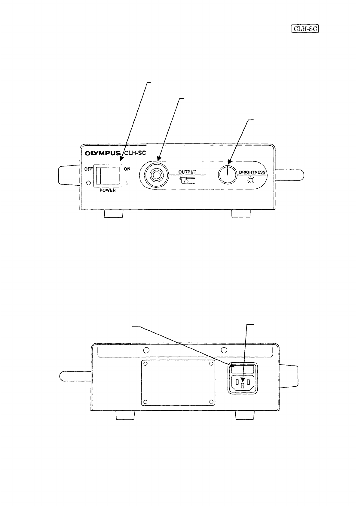
4. Nomenclature
4-1. Front panel
PRODUCT SPECIFICATIONS
1. Power switch
2. Outpu t connector
3. Brightness control
1. Power switch
Push the right side t o turn on the unit. The switch lamp lights and the illumination lamp
(halogen) lights up.
2. Output connector
Supplies an illumination light to the scope and light guide cable connected.
3. Brightness control
Turn clockwise to increase brightness and counterclockwise to darken.
4-2. Rear panel
1 . Fuse box
2. Inlet
1. Fuse box
Contains the fuse to prevent a fire due to the light source or oth e r danger when en error occurs.
2. Inlet
Connects the power cord.
1-4
Page 8
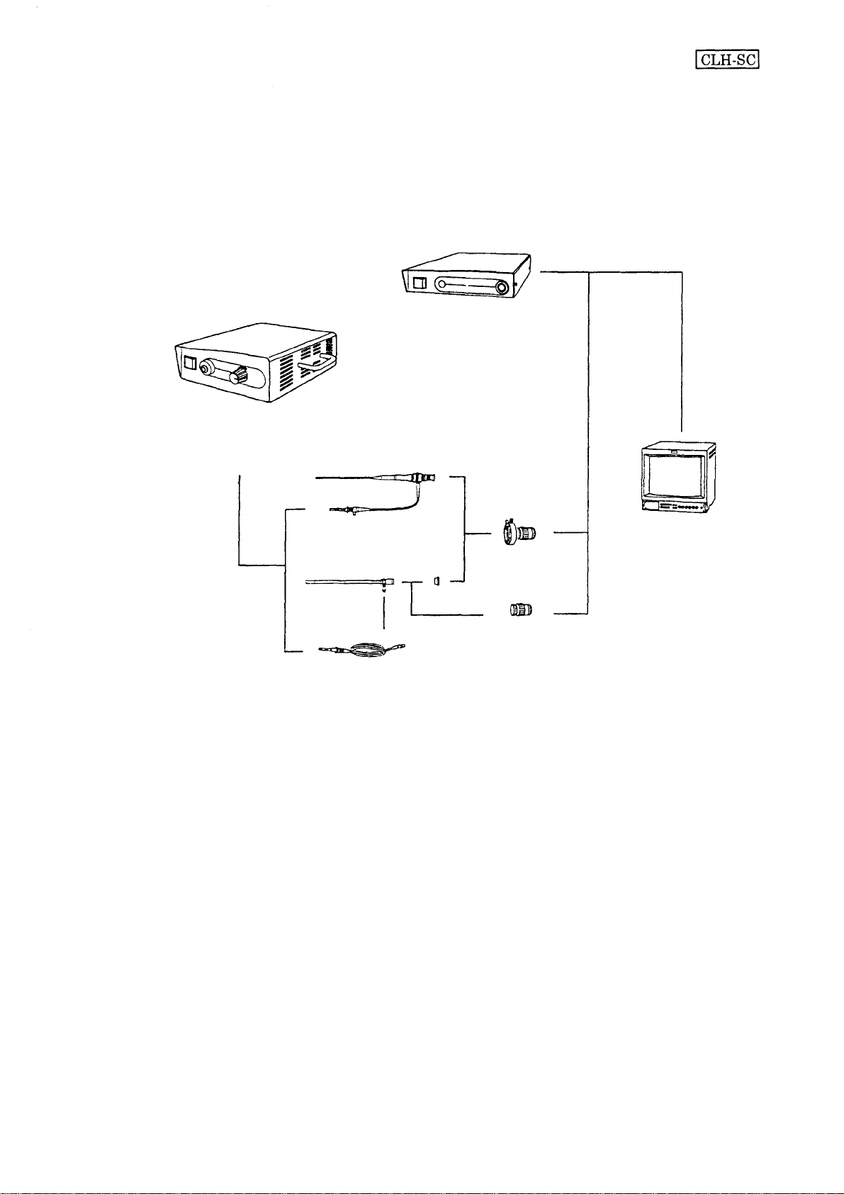
System Diagram
High intensity light
source unit
(CLH-SC)
PRODUCT SPECIFICATIONS
OES video system
(OTV-SC)
Endoscope
Rigid scope
Light guide
Video adapter
Video adapter
Video mon ito r
for endoscope
OEV
series
1-5
Page 9

DESCRIPTION OF BLOCK
2. DESCRIPTION OF BLOCK
1. Operation of Block
Operation of the CLH-SC is described using a block diagram (2-2).
Power supplied on the power cable is applied to the interlock switch through two fuses. The power
passing through the interlock switch is applied to the power switch on the front panel and is then sent
to the terminal block. The power is returned from the live side to the terminal block through the
thermo-fuse provided on the side of the power switch. The thermo-fuse operates to stop all functions
and avoid a danger wh en the fan stops, t he air duc t is blocked and the main body is abnormally heated.
The nominal operating temperature of the thermo-fuse is 117°C.
The power of 15 VAC for lighting the lamp is decreased by the transformer and is applied to the
secondary side to supply power to the lamp. The DC fan is supplied with the power that is obtained by
rectifying the lamp power supply by a diode and then smoothing by a capacitor. The transformer is
provided with a thermo-fuse of 135°C to prevent overheat, but the fuse can not be replaced. If the fuse
blows, the transformer must be replaced. This power supply circuit is provided on the UPCH10 board.
A branch from the transformer to the lamp socket, a fa n rectifying/smoothing circuit and two
connectors to supply power to the f an are provided.
2-1
Page 10
2-2
DESCRIPTION
OF
BLOCK
UNIT NAM E
BLOCK DIAGRAM
MODEL
CLH-SC
Page 11

3-1
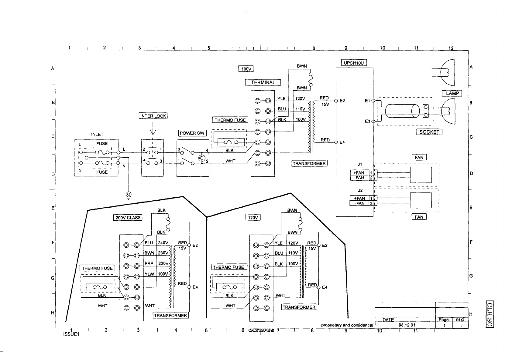
120V
3.
CIRCUIT
DIAGRAM
CIRCUIT
UNIT NAME
120V
DATE
99-01
DIAGRAM
MODEL
CLH-SC
PAGE
1/4
Page 12

3-2
220V
CIRCUIT
UNIT NAME
220V
DATE
99-01
DIAGRAM
MODEL
CLH-SC
PAGE
2/4
Page 13

3-3
230V
CIRCUIT DIAGRAM
UNIT NAME
230V
DATE
99-01
MODEL
CLH-SC
PAGE
3/4
Page 14

3-4
240V
CIRCUIT
UNIT NAME
240V
DATE
99-01
DIAGRAM
MODEL
CLH-SC
PAGE
4/4
Page 15

Symptoms
TROUBLESHOOTING
4. TROUBLESHOOTING
1. Power is not supplied.
2. The lamp does not light at all, burns out soon or turns off after once turning on.
3. The fa n does not work.
4. Brightness is insufficient.
5. Light can not be controlled.
4-2
4-3
4-4
4-5
4-6
4-1
Page 16

[Symptom: Power is not supplied.]
Start
Is power provided at
the inlet?
TROUBLESHOOTING
NO
The supply voltage is abnormal,
or the power cord is defective.
Is power provided in the
input side of the power
switch?
Is power provided in the
output side of the power
switch?
Is the thermo-fuse
conducting?
Is the voltage at the
terminals E1 and E3 of
UPCH10U 15 V AC?
NO
The interlock switch is
defective.
NO
The power switch is defective.
NO
The thermo-fuse is broken.
NO
The transformer is defective.
Check conduction of the wires and
connection of the terminals and
connectors.
End
4-2
Page 17

TROUBLESHOOTING
[Symptom: The lamp does not light at all, burns out soon or turns off after once
turning on.]
Start
Is the lamp burnt?
YES
Measure the voltage applied to
the lamp (with the lamp
connected).
1 00 V c l ass 15 V±0.75 V
200 V class 14.6 V±0.75 V
Does the voltage meet
the standard?
NO
Replace the lamp, and
age it for a while.
YES
Is the lamp burnt
soon?
Check the voltage
supplied to the
transformer.
NO
Does the voltage meet
the rating?
YES
Is the contact of the lamp
socket deteriorated?
Check connection of the
terminals and boards, and
check the state of the harness.
End
YES
YES
The transformer is defective.
(Replace the transformer)
Replace the lamp socket.
Connect power that
meets the rating.
4-3
Page 18

[Symptom: The fan does not work.]
Start
TROUBLESHOOTING
Do the both t w o fans
work?
NO
Check the voltage applied to
the fan.
Is l6.5±0.75 V DC
applied?
Only one fan works.
Check wiring and connection
of the connectors.
YES
The fan is defective.
Change connection o f
the connectors.
Do the fans work?
YES
The fa n is defective
(on e fan).
Measure the voltag e applied to
the lamp (with the lamp
connected).
10 0 V class 15 V±0.75 V
200 V class 14. 6 V±0.75 V
Does the applied voltage
meet the rating?
NO
* The rated voltage of the fan is 24 V
DC, but the f an works normally if the
supply voltage is in the operating
range o f 1 0 - 2 7 . 6 V DC.
YES
The power supply board UPCH10U
is defective. (diode/capacitor)
Check wiring and connection of the
connectors.
4-4
Page 19

[Symptom: Brightness is insufficient.]
Start
Check the lamp for
deterioration (darkness).
NO
Is the lamp normal?
TROUBLESHOOTING
Replace the lamp.
Is the lamp correctly
mounted?
Measure the voltage applied to
the lamp (with the lamp
connected).
10 0 V class 15 V±0.75 V
200 V class 14.6 V±0.75 V
Does the applied
voltage meet the
rating?
Is the mechanical iris
normal?
NO
NO
NO
Mount the lamp correctly.
Check the supply voltage.
Does the supply
voltage meet the
rating?
Connect power that
meets the rating.
The transformer is defective.
NO
Replace the lamp.
Repair the mechanical iris.
4-5
Page 20

[Symptom: Light can not be controlled.]
Start
Check to see if t he control
knob on the front panel
makes idle rotation?
TROUBLESHOOTING
Does the control
rotate idly?
Does the shaft rotate?
Check the structures of the
mechanical iris and others.
Does the mechanical
iris work?
YES
NO
NO
Tighten the ACU screw
to fix the control.
Check to see if the shaft
is caught by the stopper
screw?
Replace the mechanical
iris unit.
End
4-6
Page 21

DISASSEMBLING/ASSEMBLING PROCEDURE
5. DISASSEMBLING/ASSEMBLING PROCEDURE
1. Precautions on Disassembling/Assembling
Replace the parts and wires to the original positions.
For electrical safety and standard, be sure to reassemble the following parts to the original
states.
Insulation tube and mylar sheet
Cables clamped and separated from the heating parts or high-voltage parts
Cover screws with a toothed lock washer to suppress a radiation noise
Use the specified parts.
The parts used in this unit are designed protective against vibration, heat and high voltage. Be
sure to select the parts with the same characteristics from the parts list when replacing the
parts.
Be careful when disconnecting the cable housing.
Don't pull the cable. Be sure to use the special tool.
2. Jigs and Tools
No.
1
2
3
4
Phillips screwdriver No. 2
Name
No.
OT0376
Specification
Remarks
3. Assembling
Reverse the disassembling procedure.
5-1
Page 22

4. Disassembling
DISASSEMBLING/ASSEMBLING PROCEDURE
1. Top cover
(1) Remove the door by turning the knob.
(2) Remove the eight screws which secure the
top cover to the m ai n body.
Phillips screwdriver No. 2
(3) Remove the top cover from the main body.
5-2
Page 23

DISASSEMBLING/ASSEMBLING PROCEDURE
2. Upper he a t shielding plate
(1) Remove the three screws which secure the
upper heat shielding plate to the main
body.
Phillips screwdriver No. 2
(2 ) Remove the upper heat shielding plate
from the main body.
E1
E3
3. UPCH10U
(1 ) Remove the terminal of Socket harness
from the UPCH10U board.
(2) Remove the lead terminal of the
transformer from the UPCH10U board.
E4
(3) Remove the connector of the fa n U fro m the
UPCH10U board.
5-3
Page 24

DISASSEMBLING/ASSEMBLING PROCEDURE
(4) Remove the two screws which secure the
UPCH10U to the chassis.
Phillips screwdriver No. 2
(5) Remove the UPCH10U from the chassis.
4. Fan
(1) Re m ov e th e t w o screws which secure the
fan to the chassis.
Phillips screwdriver No. 2
(2) Remove the fan from the chassis.
5. Terminal block
(1) Remo ve t he t w o screws which secure the
terminal block to the chassis.
Phillips screwdriver No. 2
(2) Remove the terminal block fro m the
chassis.
5-4
Page 25

DISASSEMBLING/ASSEMBLING PROCEDURE
6. Transformer
(1) Remove the four screws which secure the
tr ansforme r to the chassis.
Phillips screwdriver No. 2
(2) Remove the transformer from the chassis.
7. Frame
(1) Remove the three screws which secure the
frame to the chassis.
Phillips screwdriver No. 2
(2) Remove the frame from the chassis.
8. Diaphragm
(1) Remove the three screws which secure the.
diaphragm to the chassis.
Phillips screwdriver No. 2
(2) Remove the diaphragm from the chassis.
5-5
Page 26

EXPLODED PARTS DIAGRAM
6. EXPLODED PARTS DIAGRAM
6-1
CLH-SC
COVER & SHASSY
FIG.
1/3
Page 27

EXPLODED PARTS DIAGRAM
6-2
CLH-SC
MAIN UNIT
FIG.2/3
Page 28

EXPLODED PARTS DIAGRAM
6-3
CLH-SC
CABLE
FIG.3/3
Page 29

7. PARTS LIST
PARTS LIST
PARTS No.
DB068500
DH205100
DH305600
DK521600
DY243000
DY243100
DY249300
GC224100
GC482000
GC499200
GC501500
GC505000
GC520300
GC520400
GC520500
GC520600
GC521000
GC521100
GC521200
GC521300
GC521700
GC521900
GC522000
GC624700
GD462300
GD462400
GD462700
GH371300
GH374300
GH377000
GJ423400
GJ423500
GJ423600
GJ423700
GJ440600
GJ440700
GJ449600
GJ530200
GJ558800
GJ558900
GJ559000
GR326800
GS285000
GS321800
GU1 96200
GU1
98900
SM370900
BNW4SZ
C6N4SZ
CBK3x8SA
CCUK3x16SZ
CCUK3x30SZ
CCUK3x4SZ
INDEX
PARTS NAME
1-A1
FUSE
2-A3
TERMINAL
1-A3
FUSE
POWER CONNECTOR
1-A3
1-D4
POWER SW
1-D4
POWER SW
2-A2
INTER L O CK SW
1-A2
CE PLATE
PLATE MD151
1-A1
1-A2
SCREW
WASHER
1-B2
J CAUTION PLATE
1-D1
MAIN SHASSY
1-D3
COVER
1-A1
FRAME
2-B3
LAMP BASE
2-A2
TOP HEAT STOPPER BOARD
1-C2
DOOR
1-B2
HEAT STOPPER BOARD
2-B2
2-D3
1-D1
1-D3
2-A2
2-C4
1-A3
2-C2
2-B1
3-D3
1-C4
1-B4
2-D1
2-B4
2-B4
1-A2
2-C2
1-D1
2-A1
2-A4
1-B2
2-A3
2-A3
1-B2
2-A3
2-D3
1-B2
1-D3
1-B2
1-A2
1-A2
1-A1
1-D4
1-A1
1-C4
FAN HOLDER
HANDLE
KNOB
KNOB CAP
SPACER
J PLATE
E PLATE
J LAMP PLATE
SLIDE SCREW
RING
E LAMP PLATE
UPCH10U
INLET INTER-HU
INTER SW-HU
SOKET-HU
THERMO-HU
FAN-U
PANEL PLATE
FOOT
IRIS U
TRANSFORM
TRANSFORM
CUL SEAL
BOUL BOARD
PLATE
SPRING U
GND-HU
SUB FOOT
WASHER
SCREW
SCREW
SCREW
SCREW
SCREW
SPECIFICATION
POWER SW
POWER SW
INTER LOCK
INLET INTER-HU
INTER SW-HU
SOKET-HU
THERMO-HU
FAN-U
GND-HU
WE303014
WE1
78003
WE1 39006
WE139017
WE1 39034
WE139006
REMARK
100V CLASS
200V CLASS
200V CLASS
JAPANESE
ENGLISH
100V
120V
100V CLASS
200V CLASS
7-1
Page 30

PARTS LIST
PARTS No.
CCUK3x6SZ
CCUK4x6SZ
AB6x8SB
CSK3x6SA
CUKSK3x10SZ
HCBK3x6SA
HWB4SA
INDEX
1-C2
2-C2
1-A1
1-A2
1-B4
1-A3
2-A3
PARTS NAME
SCREW
SCREW
SCREW
SCREW
SCREW
SCREW
WASHER
SPECIFICATION
WE1 39002
WE1 39005
WE402456
WE1 06060
WE168012
WE1 29002
WE306009
REMARK
7-2
Page 31

OLYMPUS OPTICAL CO., LTD.
San-Ei Building, 22-2, Nishi Shinjuku 1-chome, Shinjuku-ku, Tokyo, Japan
OLYMPUS OPTICAL CO., (EUROPA) GMBH
(Premises/ Goods delivery) Wendenstrasse 14-16, D -2 00 9 7 Hamburg, Germany
(Letters: Postfach 104908, D-20034 Hamburg, Germany)
OLYMPUS AMERICA INC.
Two corporate Center Drive Melville, N. Y.
KEYMED (MEDICAL & INSTRUMENT EQUIPMENT) LTD.
KeyMed House, Stock Road, Southend-on-Sea, Ess ex SS2 5QH, United Kingdom
OLYMPUS SINGAPORE PTE LTD
BLK 211, Henderson Road No. 13-03, Henderson Industrial Park, Singapore 0315
ENDOSCOPE MARKETING DIVISION
Printed in Japan
02.'99 W067B
 Loading...