

Page 1

OLYMPUS SYSTEM MICROSCOP
MODEL
REPAIR
CH
MANUA
OLYMPUS
Page 2

1.
REPAIR TOOLS
AND
GREASE
CONTENTS
..
2. EXPLODED PARTS
DIAGRAMS
....................•......•.....•.....
3. DISASSEMBLING PROCEDURES FOR CHA·F-3 6
4. REASSEMBLING PROCEDURES FOR CHA·F-3
5. DISASSEMBLING PROCEDURES FOR C·CH CONDENSER
6. REASSEMBLING PROCEDURES FOR C·CH CONDENSER
7. DISASSEMBLING PROCEDURES FOR C-CL
8. REASSEMBLING PROCEDURES FOR C-CL
9.
OVERALL
10. DISASSEMBLING
11. DISASSEMBLING
REASSEMBLY
AND
AND
AND
ADJUSTMENT
REASSEMBLING PROCEDURES FOR CHA-F
REASSEMBLING PROCEDURES FOR C-MVR -45
LIGHT
LIGHT
EXiT
EXiT
HOLDER
HOLDER
2
17
31
34
37
38
38
40
Page 3

TO
OLYMPUS
MICROSCOPE
SERVICING
PERSONNEL
CH Series Microscopeiswidely
specimens. Since
at
your
shop.
As
you
know,
preceding BH Series.
this
microscopeisfrequently
Accordingly,
this
the coarse and fine adjustment mechanismofCH Seriesisnearly the
The
servicing personnel having experience in repairofBH Series
repair CH Series.
However,
ment
The
as
illustrated below.
attention
mustbepaidtothe
guide, and accordingly
old and new types
The
CHA-F
this
of
the
old
one was switchedtothe
(Old type)
AA872000
used
throughout
the
operated
manual shouldbehighly
fact
that
CH Series
series
current
currently
CH Series can
uses
new and
new one at
world
for
for
routine
helpful
has
undergone
old
be
discriminated
training
for
servicing personnel.
students and inspecting various
microscopy,itistobe
often
sameasthatofthe
can
therefore easily
modificationofits coarse adjust-
typesofcoarse adjustment guides.
from
each
other
by
a vertical line
the
beginningof1979.
CHA-F-3
(New type)
AA819500
repaired
Vertical
This
manual describes repairing procedures
separatelyatthe
CH Series adopts
cedures
"R
ight
of
the
side" and
last part.
the
binocular
"left
binocular
tube, reference should thereforebemadetothe
side" used in descriptions denote thoseasseenbythe
position.
In
addition,
personnel should refer
the mechanical stageofModel
to
this
manual.
line marked
tube
whichisquite
for
the new
typeofmicroscope
the
sameasthatofthe BH Series.
IMTisnearly the
first,
and those
repair manual
for
microscopist in his observing
sameasthatofCH-MVR,
for
the
For
repairing pro-
BH Series.
and
the
old
type
servicing
Page 4

Requisites
1. First
2. Never fail
a)
b)
for
of
all, ascertain
to
Find
out
Prior
to
repairs:
check
what
repair,
efficicent way.
3. After completing
microscope
Be
4.
carefu I
specified
5. Make repairs
to
not
for
make
purpose.
promptly
what
partsofthe
the
entire
functionofthe
prts are defective and
think
the
sure no
to
deform repair
of
the
repair, check
defect
and accurately.
microscope
the
.userorownerofwhich wishes youtorepair.
microscope before you commence its repair.
how
much
they
are damaged.
best possible
the
functionsofnot
orderofdisassembling
only
shouldbeleft unremedied.
parts
during
the
assembly; make it practicetouse tools and jigs
the
the
re-assembled parts
defective partsina most
but
also
the
entire
Page 5

1.
REPAIR
1-1
Regular Tools
TOOLS
AND
GREASE
OTOOll
OT0015
OT0016
OT0017
OT0023
OT0035
OT0044
OT0216
OT0317
OT1027
OTl131
OTl141
Setofscrewdrivers (6 pes.)
Phillips screwdriver (medium size)
Phillips screwdriver (large size)
Screwdriver (small size)
Handle
Tweezers (special made)
Torque
Set
Thickness
Alon
Shellac (20
Phillips screwdriver tiP. using
1-2 Grease
OT2006
OT2008
OT2010
OT2012
1-3 Special Jigs and Tools
KKACU2.5
KKAA7828
KAA8716
K
KC-2010
8-KC0026
8-KC0027
Allen
Pin face wrench
Pin face wrench
Tool
Jig
Spoon
B-KC0028 Jig
SKN0003
Gauge
CHKC0001 Jig
CHKC0002
CHKC0003
Jig
Support
of
small sizeofPhillips screwdriver
screwdriver
of
Allen
wrenches (8 pes.)
gauge
Alpha
g)
wrench
for
for
receptacle balls
for
for
receptacle balls
for
for
adjusting movementofC-MVR
for
adjusting movementofC-MVR
with
holding
balls
checking
frame
straight handle
for
fine adjustment
gear
stage
for
C-MVR
tilt
OT0023
alignment
-1-
Page 6
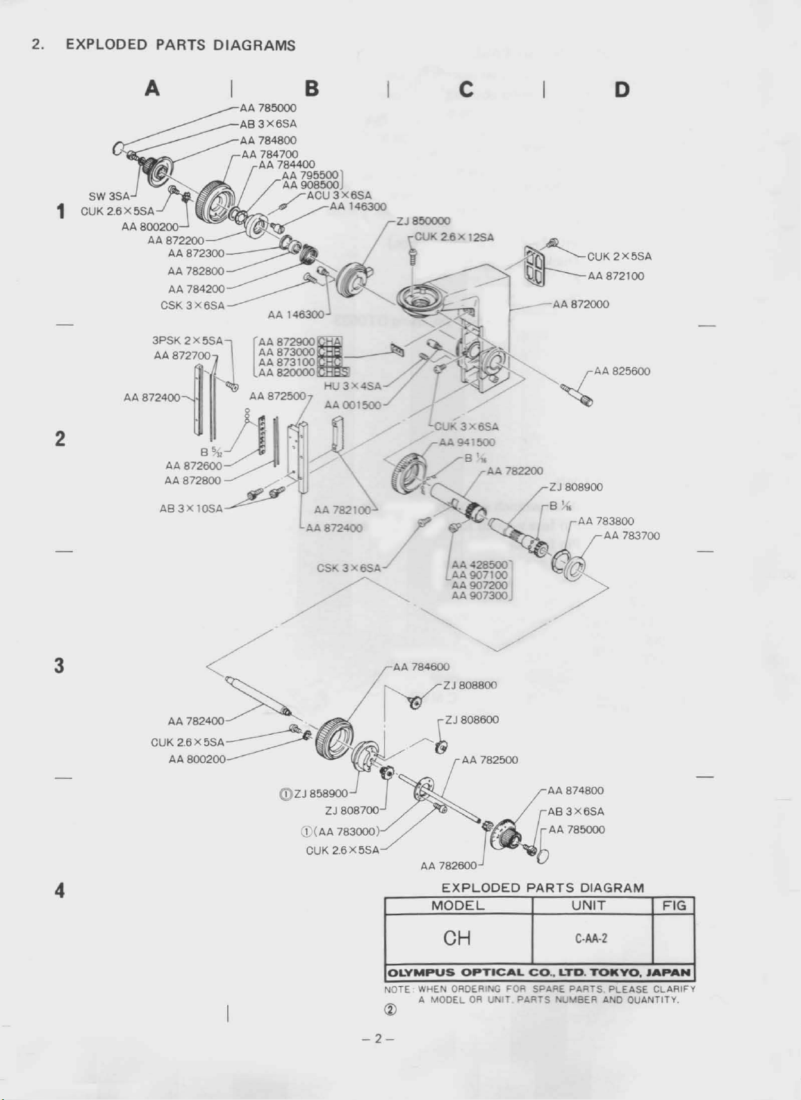
2.
EXPLODED
PARTS
DIAGRAMS
I B
c
A AA 785000
AB3X6SA
AA
~
;:~~.!f~/~
1
2
AA8002OO2200~~
AA87
U"'~.~~
AA872300
AA 782800
AA 784200
3X6SA
CSK
3PSK
2X5SA
AA872700
AA872800
AB3X
Q
10SA
784800
84700
AA
~A
/
AA
AA87
AA
[
AA 820000
• AA 872500
~
7844OO795500J
AA
500
AA~U3X6SA
AAI46300
ZJ850000
i
8729003000
873100
AA
AA872
782100"
• -
CUK 2.6 x 12SA
--CU
...
3X6SA
A.>
941500
~ .
B.
h(
r
AA
~
82200
7
/B'"
~G
lO
r
o
CUK2X5SA
AA 872100
AA 872000
~AA825800
ZJ
808900
AA
783800
AA 783700
CSK 3 6SA
/'
l~~~
AA907200
AA 907300J
/
3
AA 784600
ZJ
808800
~ZJ808600
(;
AA
782500
""""'!l4::
AA 7
82600
4
I
OLYMPUS
NOTE:MODELORUN
~
EXPLODED
MODEL
CH
OPT
HEN ORDERING
ICAL
FOR SPARE
IT
PARTS
::
PARTS
CO..LTD.
filUM
GRAM
DIA
UNIT
C-AA·2
YO
TOk
P~~~SA~~
EASE CLARIFY
OUANTITY.
JAPAN
.
FIG
~
-2-
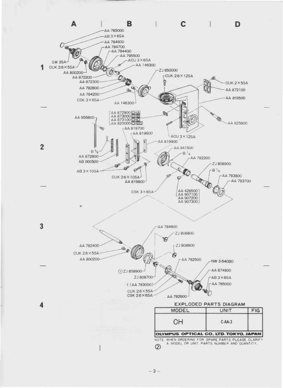
Page 7
~
AA78~
B
c
AB3X6SA
~
O:~;:~~?f
1
AA800200
AA872200
~
AA
872300
AA782800~
AA 784200
CSK
3 XBSA
AA 784800
AA
~~4i~400
AA
795500 XBSA
ACU3
~!~
/.
AAI46300
~~
"-
_______
~
AA14B3OO
2J850000
~CUK
2.B
X 12SA
o
~~CUK2X5SA
~AA872100
AA 819500
AA
------
8729003000.
AA955600
2
,,",~gJ
AB 000500
AB3X10SA
•
3
AA
782400
CUK 2.BX5SA
AA800200
AA87
[
AA8=
AA 8 AA 819700
J
CUK2.BX10SA
~
AA 819800
/'
AA819600
~
CSK 3XBSA
'AA825600
lACUjX12SA
AA 819900
AA941500
<
K/"~
/
,~
l:
AA
428500]
AA
907200
AA
907100
AA907300
AA
784600
2J808800
2J
808600
/"~
AA 782500
:"7~~
AA 783700
/
NW
3-54080
4
FIG
toLYMPUS
NOTE
-3-
WHEN
A
MODEL
CH
QRDERIN
OP
TICAL
OR
CO.,
G FOR SPARE
UNIT
PARTS
D
LT.
PAB~~S
NUM
TOt(
yo
PLEASE
AND
........
•
CLARIFY
QUANTITY,
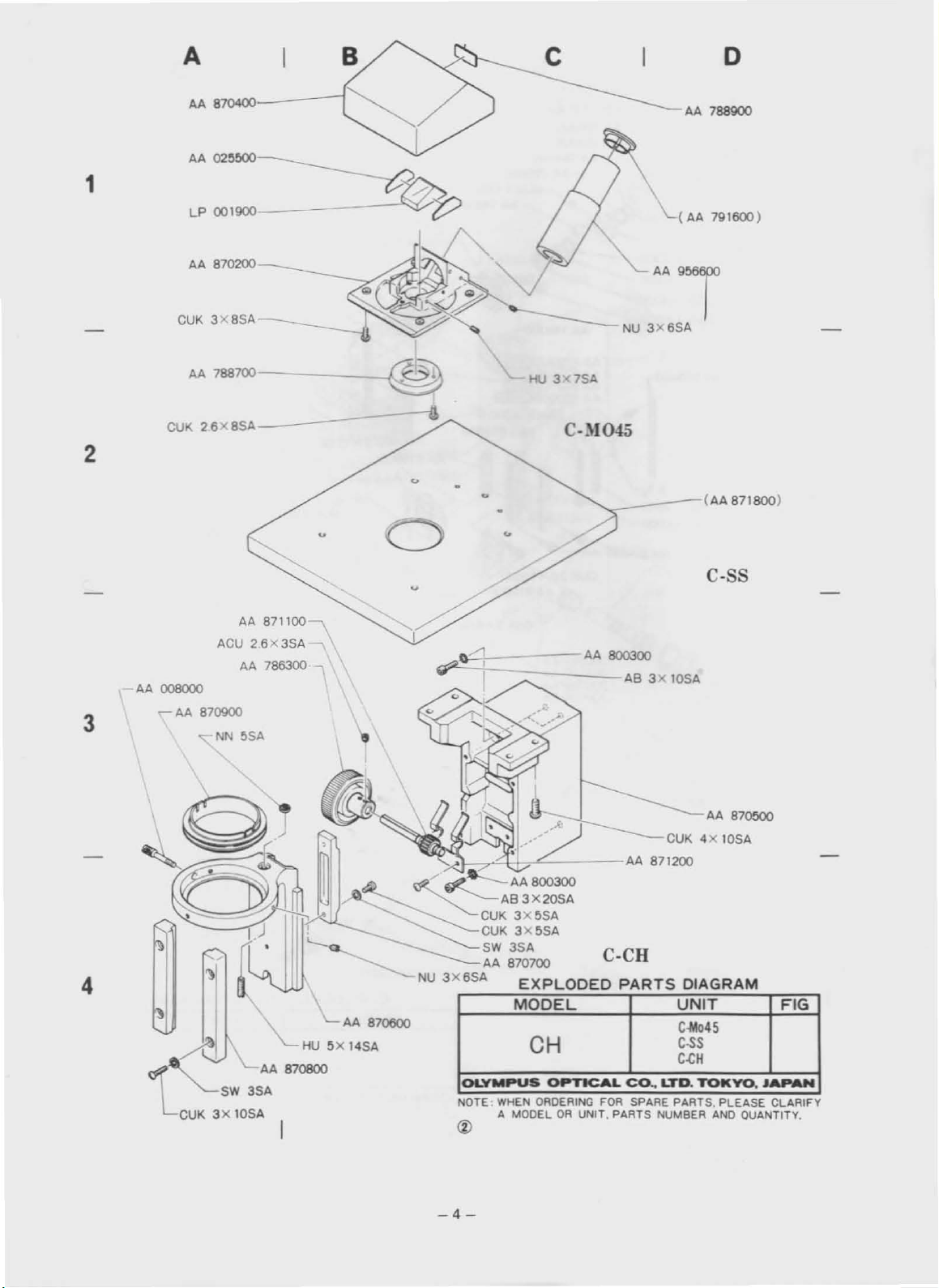
Page 8
AA
87ססoo
CUK4X10SA
~~-r'*l/~C-_--
<
fIZ...~AA
____
-z::::--
CUK
CUK3X5SA
NU
4
CUK
3X
SW
10SA
\.
AA 870800
3SA
"-
L
AA
HU5X14SA
870600
3X6SA
OLYMPUS
NOTE:
800300
AS
3X 20SA
3X5SA
SW
3SA
AA
870700
EXPLODED
MODEL
CH
OPTICAL
WHEN
ORDERING
A MODELORUNIT. PARTS NUMBER
AA
871200
C-CR
PARTS
DIAGRAM
UNIT
C-Mo45
C-SS
FIG
C<:H
Co..
lro.
TOKYO.
FDA SPARE PARTS. PLEASE CLARIFY
AND
JAPAN
QUANTITY,
-4-
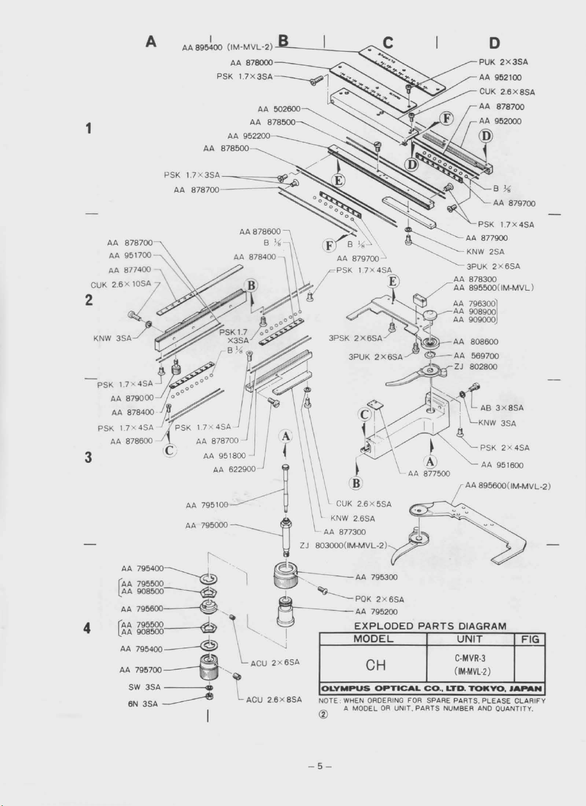
Page 9
1
AA 878700
AA
951700
AA 877400
CUK 2.6x 10SA
2
A
PSK
AA
AA 895400
1.7
I
(IM-MVL
AA
PSK
X3SA
-~==::::5Il
878700-------,'"
-2)
878000-
--'--_--..!..
__
---/
-.<
PUK
o
2x3SA
-PSK
3
4
17'
PSK
AA
879000
AA
878400
17x4SA
AA
878600 C
4SA j
000000
~oo"
/ I
J~~
J'i
PSK
17<4SA
AA
878700
AA
AA
795100 \ \
AA
79!iOOO
AA
f'
AA795400~
AA
795600
[:
AA
908600"'<=l7
A""
. a POK
AA 795600
(AA
795600·.L
lAA
908600 g I
AA
795400
AA
795700~·'
SW
3SA
6N
3SA
--------e
~
--®
~
..
I
951800
622900
'1
I
l
'-ACU
ACU
;:---
~
2X6SA
2.6X8SA
3PSK 2X
A(
\ l
6SA.J
3PUK
K~~\:::5SA~
~
AA
877300
ZJ
803000(lM-MVL-2) -
~
--J
----
I
~
OLYMPUS
NOTE
<Z)
AA
795300
AA
795200
EXPLODED
MODEL
CH
WHEN
ORDERING FOR SPARE PARTS, PLEASE CLARIFY
A MODELORUNIT. PARTS NUMBER
AA
808600
2X6SA~
-_.
~ZJ
~-
-d~,).n.
AA
802600
~
569700
AS
/~~
2x6SA
OPTICAL
II
AA
877500
.•
PARTS
CO.•LTD.
~
r
I
KNW
.g
'-
PSK2X4SA
AA
AA 895600(IM-MVL-2)
DIAGRAM
UNIT
C·MVR-3
(IM-MVL-2)
TOKYO.
AND
3x8SA
3SA
951600
FIG
JA
....
QUANTlTV,
N
-5-
Page 10

3.
DISASSEMBLING
PROCEDURES FOR CHA-F-3
Fig. 3-1
",--
..
C-AA:
C-CH:
~
C-AA
C-BDA
C-CL:
C-BDA:
3- Detaeh Electrical
Arm
Condenser holder
Light
exit
Electrical
base
plate
base
plate C-BDA
from
the
m croscope stand.
-1
AB4x16SA
SW4SA
C-BDA
CUK3x6SA
3-
3-'-2
3-1-3
Set the microscope stand upside
en
remove
from
the
Remove Screw
base
four
fixing
plate.
CUK3x6SA
Screws
from
,ng line.
Detaeh
the
electrical
base
platebylihing
down
AB4x16SA
(See
Fig. 3-2)
the ground-
(See
Fig. 3-2)
and
it.
Fig. 3-2
Fig. 3-3
CUK3x6SA
3-2
By
removing three Screws
mount
Light
exit
C-CL.
CUK3x6SA,
(See
Fig. 3-3)
dis-
-6-
Page 11

3-3 Disassemble Condenser holder C-CH
ing three Screws
AA800300.
AB3xlOSA
and three
by
remov·
Washers
Fig.34
3-3-1 Rack
limit.
visible through the notch formed under
Holder
3-3-2 Rack
limit
up
the condenser holder
Remove Screw
AA870600.
down
and then remove
the condenser holdertoits lower
AB3xl0SA
two
Screws
to
its upper
which
(See
Fig. 3-4)
AB3x1OSA.
(See
Fig. 3-5)
is
Fig. 3-5
Fig. 3-6
, '
..
. .
'1'
'
...
AA819800
j-
..
•
3-4 Disassembling procedures
guide.
NOTE:
For disassembling procedures
adjustment guide
ofthis
3-4-1 Detach
manual.
removing
two
of
CHA-F (old type),
Fixing pieces
two
ScrewsCUK2.6x10SA.
for
coarse adjustment
of
the coarse
AA819800
(See
see
10-1
by
Fig. 3-6)
-7-
Page 12

3-4-2 Remove three Screws
gu
ide
AA819700.
AB3x1OSA
from
(See
Inner
Fig. 3-7)
AA819700
.'
,
-.
-~-
-
J .
"
Fig, 3-7
•.•
AB3xl0SA
-
. 1 .
~
.,
3-4-3 Loosen
AA819900_
two
Screws
AB3x10SA
(See
on Rack
Fig. 3-8)
Fig.
3-8
3-4-4 Disassemble Inner guide
Bal.s B 5/32 and Casing
isassembled together
with
AA819700.
AA872600
the inner guide.
Eight
are
-8-
Page 13
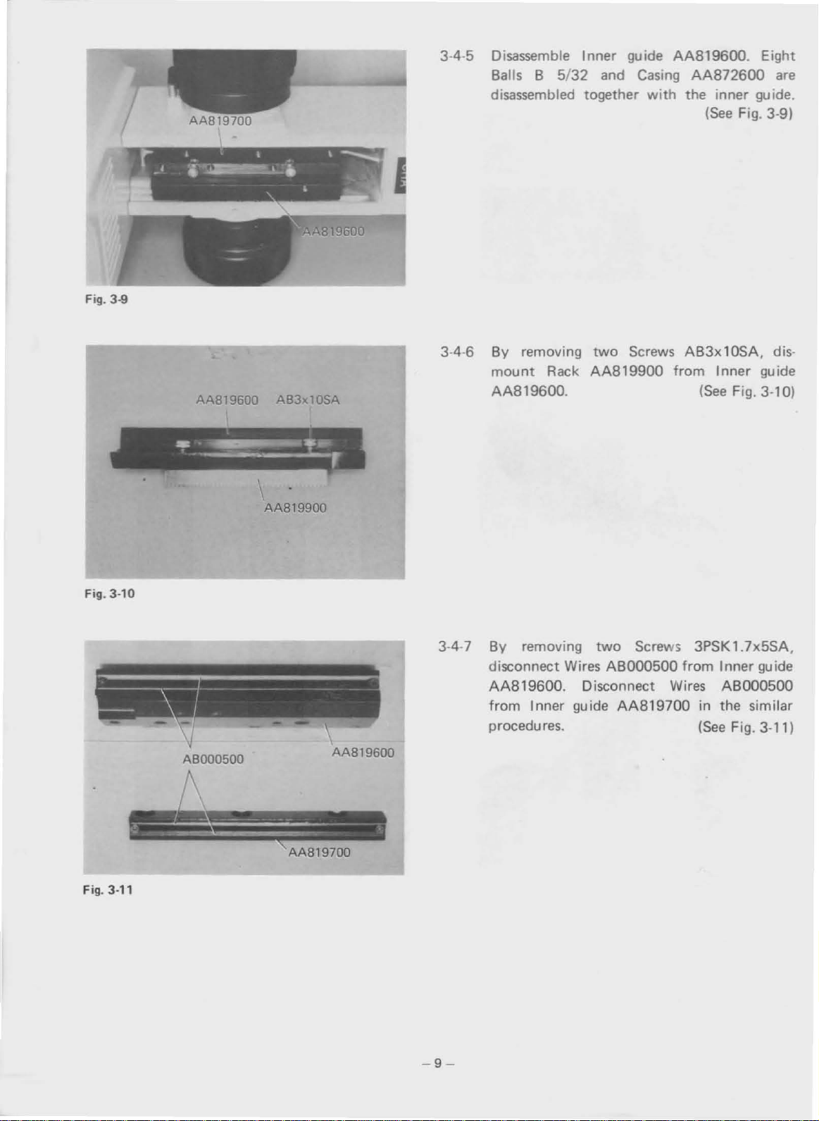
3-4-5 Disassemble Inner guide AA819600. Eight
8alls 8 5/32 and
disassembled together
Casing
with
AA872600
the inner guide.
(See
are
Fig. 3-9)
Fig. 3-9
-,~..
I
· ,
AA819600
,
AB3xl0SA
AAB19900
'-"'"
,..
'
3-4-6
By removing
mount
AA819600.
Rack
two
Screws AB3x10SA. dis·
AA819900
from Inner guide
(See
Fig. 3-10)
Fig. 3-10
Fig. 3-11
ABOO0500
AA819600
AA819700
3·4-7 By removing
disconnect Wires
AA819600. Disconnect Wires ABOO0500
from Inner guide
procedures.
two
Screws 3PSK 1.7x5SA.
ABOOO500
AA819700
from Inner guide
in the similar
(See
Fig. 3-11)
-9-
Page 14
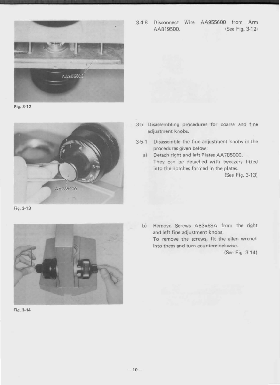
Fig. 3-12
3-4-8 Disconnect Wire
AA819500.
AA955600
(See
from
Fig. 3-12)
Arm
Fig. 3-13
AA785000
3-5 Disassembling procedures
adjustment knobs.
3-5-1 Disassemble
the
fine
adjustment knobs in the
procedures given below:
a)
Detach
They
into
b) Remove Screws
and
To
into
right
can
be
the
notches
left
fine
remove
them and
and
left
PlatesAA785000.
detached
formed
AB3x6SA
adjustment knobs.
the
screws,
turn
counterclockwise.
for
coarse and fine
with
tweezers
in the plates.
(See
from
fit
the alien wrench
(See Fig. 3-14)
fitted
Fig. 3-13)
the
right
Fig. 3-14
-10
-
Page 15

Fig.
3·15
c)
Pull
directions.
3-5-2 Detach
out
the fine adjustment knobs in both
(See
Washer
AA784400.
(See
Fig:
3-15)
Fig. 3-16)
Fig.
Fig.
AA784400
3·16
3·17
3-5-3 Detach Spring AA795500.
(See
Fig. 3-17)
-11-
Page 16
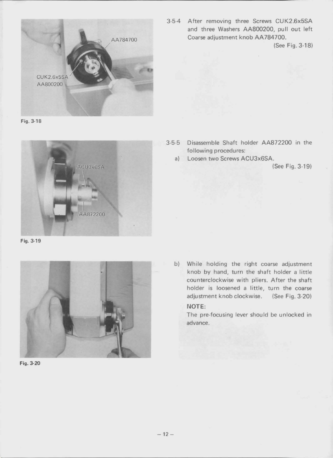
Fig.
3·18
CUK2_6x5SA
AA800200
AA784700
3-5-4
Aher
removing three Screws
and three Washers
Coarse adjustment
AA800200,
knob
AA784700.
CUK2.6x5SA
pull
out
(See
Fig. 3-18)
leh
Fig. 3-19
3-5-5 Disassemble Shaft
following
a)
Loosen
b) While
•
knob
procedures:
two
Screws
holding
by hand,
counterclockwise
is
holder
adjustment
loosened a
knob
holder
AA872200
ACU3x6SA.
the
right
coarse adjustment
turn
the shaft holder a
with
pliers.
little,
clockwise.
(See
After
turn
(See
in the
Fig. 3-19)
little
the shaft
the coarse
Fig. 3-20)
NOTE:
The
pre-focusing lever shouldbeunlocked in
advance.
Fig. 3-20
-12-
Page 17

Fig. 3-21
3-5-6 Remove Spring
AA784200.
(See
Fig. 3-21)
Fig. 3-22
3-5-7
Pullout
the right coarse adjustment
the direction indicated
3-5-8 Disassel]lble the
unit
a)
8y
Washers
adjustment
in the
removing three Screws
following
AA800200,
knob
by
arrow.
right
coarse adjustment
procedures:
disassemble Coarse
AA784600.
knob
(See
Fig. 3-22)
CUK2.6x5SA
(See
Fig. 3-23)
in
knob
and
Fig. 3-23
AA800200
AA784600
-13
-
Page 18

Fig. 3-24
AA783000
b)
By
removing three Screws CUK2.6x5SA,
detach Circular plate
c)
Detach
gears
AA787800.
AA783000.
(See
Fig. 3-24)
ZJ808600, ZJ808700 and
(See
Fig. 3-25)
Fig.
AA787800
3·25
ZJ808600
KC-2010
ZJ808700
3·5-9 Disassemble Pinion
following procedures:
a)
Set
Tool
808900, and set
Nut
AA782800.
b)
Remove the
KC-2010 on the right Gear ZJ·
Tool
nut
by
clockwise.
NOTE:
The
nutisfixed
The bearing
unit
unit
ZJ808900 in the
KKAA7828
on the
(See
turning the
with
adhesive agent.
tool
contains308alls B
left
Fig. 3-26)
counter·
1/16.
Fig.
3·26
-14
-
Page 19

Fig. 3-27
Pullout
cl
indicated
d)
Remove 8alls 8 1/16.
Pinion ZJ808900
by
arrow.
in the direction
(See
Fig. 3-27)
Fig. 3-28
AA783700
\
3-5-10
3-5-11 Disassemble the pinion bearing in the pro-
After
Screw CSK3x6SA,
bearing.
by
cedures given below:
a)
Detach Washer
It
can
arrow
removing
be
two
Screws
dismount
pulled
after the screws have
out
in the direction indicated
AA783700.
CUK3x6SA
the
been
removed.
(See
Fig. 3-28)
(See
Fig. 3-29)
and
pinion
Fig. 3-29
-15-
Page 20

Fig. 3-30
AA783800
AA941500
b) Detach Spring
c)
Remove
Knob
clockwise (in
arrow).
AA783800.
AA941500
the
direction indicated
(See
by
(See
Fig. 3-30)
turning
Fig. 3-31)
it
by
Fig. 3·31
Fig.
3·32
3·5-12 Disassemble the pre-focusing lever in the
following procedures:
a)
Remove Stopper
AA001500.
(See
Fig. 3-32)
-16-
Page 21

Fig. 3-33
AA784100
AA941600
b) Remove Lever
counterclockwise.
NOTE:
Lever ZJ850000
three parts:
Lever
Ring
Outer ring
c)
Detach Ring
AA941600
AA784100
AA784000
AA784100.
AA941600
consists
of
by
(See
the
(See
turning
Fig. 3-33)
following
Fig. 3·34)
it
Fig. 3-34
4. REASSEMBLING PROCEDURES FOR CHA-F-3
4-1
Fig.
AA941500
4-'
4-1-1
Reassemble the coarse adjustment knob.
Reassemble the pinion bearing
following
a)
Reassemble Knob
procedures:
AA783800
AA782200.
Apply
Grease
OT2006tothe thread.
unit
with
(See
in the
Bearing
Fig. 4·1)
-
17-
Page 22

Fig. 4-2
AA783700
b)
Apply
Spring
c)
Apply
and reassemble
Grease
AA783800
OT2006tothe thread crests
and reassemble
Grease OT2006toWasher
it.
it.
(See
Fig. 4-2)
AA783700
(See
Fig. 4-3)
of
Fig_
Fig_
4-3
4-4
4-1-2 Reassemble the
AA819500
by
and Screw CSK3x6SA.
pinion
using
two
bearing
Screws
with
CUK3x6SA
(See
Fig. 4-4)
Arm
-18
-
Page 23

Fig.4·5
ZJ808900
}
Thread
ZJ808900
B·KCOO27
B
1/16
4·1·3 Reassemble Pinion shaft
procedures given below:
a)
Apply
Grease
OT2012
ZJ808900.
NOTE:
Take care
b)
Set 30 Balls B 1/16
nottoapply
into
greasetothe thread.
(1) Set Jig B·KC0026 on the
(2)
Apply
set
Drop
(3)
(4) Pull
Grease
them
the
out
OT2012tothe30balls and
into
Jig B-KC0027.
ballsindirection
Jig B·KC0026 in direction (B).
ZJ808900
to
the Pinion shaft
(See
the
pinion
pinion
(A).
(See
in the
Fig. 4·5)
shaft.
shaft.
Fig. 4-6)
8·KC0026
Fig.4-6
/
c)
Reassemble the
With
(1)
the microscope stand kept
insert the
pinion
pinion
shaft
with
the bearing.
upright,
shaft while taking
care
nottodrop the balls.
(2) Fell
down
holding
the balls.
the microscope stand while
the
pinion
shaftsoas
nottodrop
(See
Fig. 4·7)
Fig.
4·7
-19
-
Page 24

Fig. 4-8
B·KC0028
I
,
d) Set the
0028.
(1) Set Jig
30
Balls B
B-KC0028inposition.
1/16
by
using Jig B-KC
(See
Fig. 4-8)
Fig. 4-9
AA782800
(2) While taking care
the threadofPinion shaft
the
ballsbyusing tweezers.
(3) Remove Jig
NOTE:
Take
sufficient
be
applied
shaft.
e)
Reassemble
such a degree
dropping
out.
B·KC0028.
to
Nut
AA782800
as
not
to
apply
care
to
prevent
the thread
and
to
prevent the balls
(See
grease
ZJ808900.
(See
Fig.
grease
of
the
pinion
tightenitto
Fig. 4-10)
to
set
4·9)
to
from
Fig. 4-10
-20-
Page 25

Fig. 4-11
f)
Set
the
microscope stand
in
its initial posi-
tion.
Adjust
(1) Tighten
the
pinion shaft and
the
nuttosuch a degree
is
pinion shaft
free from unsmooth rota-
tionorplayinthe
thrust
Nut
AA782800:
direction.
(See Fig. 4-11)
(2) Note
pinion shaft
cannot
that
the
smooth if Nut AA782800istightened
much.
g)
Apply Alon Alpha OT1027tothe thread
Nut AA782800. (See Fig. 4-12)
that
rotate
the
too
of
Fig. 4-12
ZJ856400
AA782800----IU
OTl027
AB023600
~~
4-1-4 Reassemble
a)
After
making sure
free from contamination by oil
reassemble itinposition. (See Fig. 4-13)
the
pre-focusing lever:
that
Ring
AA784100
or
flaw,
is
Fig. 4-13
-21-
Page 26

Fig. 4·14
b)
Reassemble Lever AA941600 by screwing
it clockwise as far as it can
turn.
(See Fig. 4-14)
c)
Reassemble
Stopper
AA001500.
(See Fig. 4-15)
Fig. 4-15
Fig.4-16
ZJ808600
ZJ808700
4-1-5 Reassemble the right coarse adjustment
knob:
a)
Reassemble Gear
787800,
Grease
applied
ZJ808600
OT2012
to
the
mount
with Gears AA·
and ZJ808700.
should preliminarily be
shafts and th readofthe
gears.
(See Fig. 4-16)
-
22-
Page 27

Fig. 4-17
AA783000
b)
Reassemble
Screws
CU
c) Check the
as
described below:
(1)
8y
turning the
sure
creaking noise.
(2)
If
the
the following items:
Set condition
n Flaw and du
Flaw and burrs on Cover
in the bearing hole
782900.
Cover
K2.6x5SA.
gears
that
they
gears
st
AA783000
for
their
gears
can
rotating conditions
with
turn smooth
with
(See
three
Fig. 4·17)
a finger, make
with
no
cannot turn smooth, check
of
CoverAA783000
on the
gear
teeth
AA783000
of
Gear mountAA·
and
Fig.
4-18
CUK2.6x5SA
AA800200
AA784600
4·1
d)
three
~
Reassemble
Adjust
ones
Reassemble
784600
the partsorreplace them
if
necessary.
Coarse adjustment
with
three Screws CUK2.6x5SA and
Washers
AA800200.
the right coarse adjustment knob
in the following procedures:
a)
Reassemble
the knob
unit.
(See
(See
with
knob
Fig. 4-18)
Fig. 4-19)
new
AA·
Fig.
4·19
-23
-
Page 28

Fig. 4·20
b)
Reassemble Spring
c)
Reassemble 8earing
(1)
Fit
Stopper
Bearing
attached
AA784200
depressing the bearing
microscope stand.
wise
When
the
stopper
be
a
stand once again.
AA784200.
AA782200.
screw
AA872200
at
as
AA
146300
into
the
other
shown in Fig. 4-20. While
turn
as
farasit
can go. (Fig. 4-21)
itisstopped, ride the
while
allowing the bearing
little
apart
from
(See
the
end
lightly
the
the
(See
Fig. 4-20)
located on
circular
of
part
Spring
to
knob
clock-
knob
over
microscope
Fig. 4-22)
the
to
Fig. 4-21
AA784200
Fig. 4-22
Screws
Screws
AA146300onAA784100
AA
146300onAA872200
Reassembly
knob
quence
shouIdbe
ofA....B....
4-22.
of
the coarse adjustment
performed
in
C illustrated in Fig.
the
se-
-
24-
Page 29

Fig.
4·23
(2) With the bearing depressed lightiytothe
microscope stand by hand, tighten the
right coarse adjustment knob by turning
it
clockwise. Finally, tighten it firmly
while holding
the
similar tool. (See Fig. 4-23)
NOTE:
the
bearing with pliers
or
Coarse adjustment knob AA784600 can·
not
turn smooth unless Gear
assembled
in
the
gear
properly with Pinion
mountisengaged
ZJ808900
ZJ808900
in
tightening the knob.
Fig.
4·24
(3) Tighten
two
Setscrews ACU3x5SA on
8earing AA872200. (See Fig. 4·24)
4-1·7 Reassemble Coarse adjustment knob AA·
874700
and
with three Screws
CU
K2.6x5SA
three Washers AA800200. (See Fig. 4·25)
Fig.
4·25
-
25-
Page 30

Fig.
4·26
4-1-8 Reassemble Spring
2008 should
thread crests
preliminarily
of
the spring.
AA795500.
be
Grease
applied
(See
Fig. 4·26)
to
QT-
the
Fig. 4·27
AA784400
4-1-9 Reassemble Washer
2008
should
preliminarily
AA784400.
be
washer.
4-1-10 Reassemble the fine adjustment
procedures given below:
a)
Insert the
Knob
Gear
Shaft
b)
Reassemble the
right
knob
AA874800
AA782600
AA
783000
left
unit:
knob
AA784800.
Greas~
applied
(See
Fig. 4-27)
knob
(See
QT-
to
the
in the
Fig. 4-28)
Fig.
4·28
-
26-
Page 31

Fig. 4-29
c)
Tighten right and
left
Screws AB3x6SA_
(See
Fig. 4-29)
Fig. 4-30
AA819600
4-1-11 Reassemble right and
4-2 Reassembling procedures
left
Plates
for
coarse adjustment
guide.
NOTE:
For reassembling the coarse adjustment guide
CHA-F (old type), proceed
to
manual.
AA
(See
10-2
785000.
Fig. 4·30)
of
of
this
Fig. 4-31
AA819900
4-2-1
-
27-
Reassemble Inner guide
a)
Temporarily reassemble Rack
with
Inner guide
AA819600.
unit
AA819600.
AA819900
(See
Fig. 4-31)
Page 32

b)
Reassemble
9uide
AA819600
1.7x5SA and apply
two
Wires
by
Grease
AB000500
using
two
OT2010.
with
Inner
Screws 3PSK
(See
Fig. 4-32)
Fig. 4-32
- -
---
AB000500 3PSK 1.7x5SA
AA819700
AB000500
-------
3PSK1.7x5SA
/
4-2-2 Reassemble
guide
1.7x5SA and apply
two
AA819700
Wires
by
Grease
AB000500
using
two
OT2010.
with
Inner
Screws 3PSK
(See
Fig. 4-33)
Fig. 4·33
Fig.4-34
4-2-3 Connect
of
Arm
Apply
them
for
four
Wires
AA819500.
grease
OT2010tothe wires and bond
connection.
AA955600
to
(See
the guide
Fig. 4-34)
-
28-
Page 33

Fig. 4-35
4-2-4
Mount
Casing
B 5/32.
o
Apply
Grease
advance.
o The casing
pinion.
AA872600
OT2010
shouIdbe
and eight Balls
(See
Fig. 4-35)
to
the balls in
centered
with
the
Fig. 4-36
ABB77600
B
5/32
4-2·5
4-2-6
a)
Reassemble
step
4-2-1
Reassemble
step 4-2-2
Mount
the inner guide
above.
the inner guide
above_
Casing
AA872600
B 5/32 on the Inner guide
This step
is
quite similarto4-2-4
unit
prepared in
(See
Fig. 4-36)
unit
prepared in
and eight Balls
AA819700.
(See
Fig. 4-37)
above_
Fig. 4-37
AAB19700
-
29-
Page 34

Fig.4-38
AB3xl0SA
b)
Reassemble the Inner guide in alignment
that
reassembled in step 4-2-5 above.
NOTE:
The
inner guide shouldbefixedbytightening
Screw
haifa
AB3x1OSA,
turn
(180°).
and then loosened
(See
with
Fig. 4-38)
about
Fig.
4·39
4-2-7 Reassemble
using Screw
NOTE:
The
screw shouIdbe
that
Rack
about
which
fter
position ing the rack snugly by moving
the inner guide
4-2-8
a)
b)
4-2-9
a)
degree
Adjust
Loosen
10SA
A
the inner guide
adjustment knob,
AB3x1OSA.
Adjustmentofinner guide
Adjust
movable range.
two
Fixing
CUK2.6x10SA.
the guideisfree
AA819900.
half
are
used
up
pieces
tightened
a turn
for
fixing
and
down
firmly
unittothe centerofits
from
two
with
tighten
unit
AA819800
(See
Fig.
to
such a
play.
Screws
the
rack.
the coarse
two
Screws
(See
Fig. 4-40)
by
4-391
AB3x
Fig.440
-30-
Page 35

Fig.441
b)
By using a screwdriverortweezers, adjust the
to
casing
the centerofthe inner guide
(See
c)
By using Torque screwdriver
two
Setscrews GUK2.6x10SA
piece.
Tightening torque:
d)
Apply
Shellac OT1131
800
OT0044,
for
(See
g-cm
to
the screws to
prevent loosening.
e)
Finally
fix
inner guide
AA819700bytighten-
ing three Screws AB3x10SA.
unit.
Fig. 4-41)
tighten
the
fixing
Fig. 4-42)
Fig.
442
5.
DISASSEMBLING
Fig. 5-1
PROCEDURES FOR
C-GH
-31-
CONDENSER
5-1
By removing
mount
left
HOLDER
two
Dovetail
Screws
GUK3x10SA,
AA870800.
(See
dis-
Fig. 5-1)
Page 36

Fig. 5·2
AA870800
5-2
By removing
mount
two
right
Dovetail AAB70BOO.
Screws
CUK3x10SA.
(See
Fig. 5-2)
dis·
Fig. 5-3
klA008000
5-3 Dismount the condenser holder.
5-4 Disassembling procedures
5-4·1 By removing
mount
Rack
two
AA870700.
for
Screws
(See
Fig. 5-3)
condenser holder.
CUK3x5SA.
(See
dis·
Fig. 5-4)
Fig. 5-4
O''+--
CUK3x5SA
-32
-
Page 37

5-4-2 Detach
NOTE:
/AA870900
Sleeve
correct the following defects only:
(1) Miscentering
(2) Breakage
a)
Remove Setscrew AA008000.
b)
Loosen three Screws NU3x6SA_
c)
Detach
5-4-3 Remove Condenser height adjusting screw
HU5x14SA.
Fig. 5-5 NOTE:
The height adjusting screw shouldberemoved
only
ed.
a)
Remove
b)
Remove Screw HU5x14SA.
(See
Sleeve
AA870900.
AA870900
of
Sleeve
Sleeve
AA870900.
should
of
condenser
be
AA870900
Fig. 5-5)
detached
to
when the condenser heightismisadjust-
Nut
NN5SA.
(See
Fig. 5-5)
Fig. 5-6
AA871100
5-4-4 Disassemble Pinion AA871100.
5-4-5 Detach Knob
871100 by removing
AA786300
two
from Pinion
Screws ACU2.6x
3SA.
(See
(See
Fig. 5-6)
AA-
Fig. 5-7)
Fig. 5-7
AA786300
ACU2.6x3SA
-33
-
Page 38

Fig. 5-8
5-4-6
Dismount
removing
two
Pinion
Screws
holder
AA871200
CUK3x5SA.
(See
by
Fig. 5-8)
Fig. 5-9
6_
REASSEMBLING
5-4-7 Detach Stage plate
four
Screws
NOTE:
CUK4xl0SA The
stage
itisdefective
proper.
PROCEDURES FOR C-CH CONDENSER
6-1
Reassemble Stage plate
AA870500
AA871800
CUK4x10SA.
plate shouldbedetached
or
its perpendicularityisim-
HOLDER
AA871800
by
using
four
Screws
by removing
(See
Fig. 5-9)
only
when
with
Block
CUK4x10SA.
(See
Fig. 6-1)
Fill-
6-1
-34-
Page 39

Fig. 6-2
6-2 Reassemble Pinion holder
two
Screws
CUK3x5SA.
AA871200
(See
by using
Fig. 6-2)
Fig.
6·3
NU3x6SA
6-3 Set Pinion AA871100 in position.
6-4 Reassembling procedures
for
condenser holder
unit.
6-4-1 Reassemble
denser holder
Sleeve
AA870600
AA870900
Screws NU3x6SA.
(See
Fig. 6-3)
with
Con-
by using three
(See
Fig. 6-4)
Fig.64
-
6-4-2
35-
Reassemble
Setscrew
AA008000.
Page 40

6-4-3 Reassemble Rack
Washers
SW
3SA
5SA_
AA870700
and
two
by
Screws
(See
using
CUK3x
Fig. 6-5)
two
Fig. 6-5
;;;""'~AA870700
6-4-4
Apply
Grease
OT2008tothe dovetail.
6-5 Reassemble Condenser height adjusting screw
HU5x14SA.
6-6 Set
the
condenser holder
unit
in position.
(See
Fig. 6-6)
Fig. 6-6
Fig. 6-7
AA870500-
AA870800
CUK3xl0SA
6-7 Reassemble right Dovetail
two
Screws
CUK3xl0SA
3SA.
be
The dovetail should
with
the sideofBlock
reassembled in alignment
AA870500.
AA870800
and
two
by using
Washers
(See
Fig. 6-7)
SW
-
36-
Page 41

6-8 Reassemble
two
Screws
3SA.
While pushing the dovetail
left
CU
Dovetail
K3x
10SA and
AA870800
two
(See
uniformly
direction indicated by arrows, tighten the
screws.
by
Washers
Fig. 6-8)
in the
using
SW
Fig. 6-8
Fig. 6-9
AA870800
/'
6-9 Reassemble
Knob
AA876300
by
using
two
Screws ACU2.6x3SA.
knob
The
6-10 Check
shouldbeapart
the
condenser holder
about
2 mm.
for
its vertical
(See
6-9)
motion.
6-10-1
Check the dovetail
a)
When
the
tip
for
its play.
of
the condenser holder
is
swung in the right-left direction, play must
notbefeltbyhand.
b)
If
the dovetail plays, tighten the
firmly
sufficiently
arrow.
while depressing
in
the
direction indicated by
(See
the
two
screws
left
dovetail
step 6-8 above)
7.
DISASSEMBLING
PROCEDURES FOR C-CL
1L--_AA290200
LIGHT
7-1
EXIT
Remove Ring
AA871600.
NOTE:
The ring
If
it
wrench
tweezers
is
bonded at one
cannot
KKAA8716,
or
the
be loosened
similar
7-2 Disassemble the lens system:
Lens
Ring
Filter
Ring
Lens
-
37-
LA410800
AA290100
LP072100
AA290200
LA510900
cut
tool.
point
off
with
with
Araldite
Araldite.
the Pin face
by
using
Page 42

8.
REASSEMBLING
PROCEDURES FOR C-CL
LIGHT
8-1
EXIT
Reassemble Lens
AA871500.
AA410900
with
Lens
tube
9.
OVERALL
_LA410900
-
~
I
ASSEMBLY
AA87,SOll
AA290200
LP072,00
AA290,00
LA41
0800
AA87,600
AND
ADJUSTMENT
8-2 Reassemble Ring
8·3 Reassemble
8-4 Reassemble Ring
8-5 Reassemble Lens
8-6 Tighten Ring
KKAA8716.
8·7 Loosen Ring
as
not
Araldite
ing.
9-1
Reassemble C·CH
three Screws
AA800300.
See
step 3-3 above.
Filter
AA871600tosuch a slight degree
to
allow
OT1028ata
AA290200.
LP0721 00.
AA290100.
LA41
0800.
AA871600
the lens
point
unit
A83x
10SA and three Screws
by using Wrench
to
play, and apply
to
prevent loosen-
with
the arm by using
(See
Fig. 8·1)
/
•
Fig. 9-1
Adjust
9-2
9-2-1
a)
b)
c)
Measure
Thickness
and
If
d)
of
10SA.
9-2-2
Adjustment
a)
Proceedasdescribed in 9-2-1·b) above.
b) Proceed
c)
If
inserting
871800
perpendicularityofthe
Adjust
Set Stage perpendicularity
the
Apply
X direction.
in X
direction
nose
piece.
SKN0003
gaps
gauge
stage
surface.
Standard:
the standardisnot
C-CH
the standard
by
as
described in 9-2·1-e) above.
tin
and Block
in the X
Within
turning
in Y
foil
on the
OT0317
direction
is
between Stage plate
AA870500.
0.15 mm
satisfied, adjust position
three Setscrews
not
stage
.
gauge
SKN0003
stage
surface in the
direction
between
satisfied, adjust by
by
SKN0003
(See
(See
on
using
Fig. 9-1)
A83x
Fig. 9·2)
AA-
Fig. 9-2
-
38-
Page 43

9-3 Reassemble Light
Screws CUK3x6SA.
NOTE:
The
notches formed
on
positioned
the
Fig. 3-3.
exit
C-CL by using three
in
the
light
front
and rearasshown
exit
must
be
in
Sreciman
B2KC0010-
Fig. 9-3
9-4 Reassemble Electric base plate C-BDA.
(See Fig. 3-2)
9-5 Check and
adjustment
of
fine
sensitivity.
Set
the
9-5-1
components
in
Fig. 9-3.
Microscope
Objective
following accessories and checking
in
the
microscope as shown
tube}
40x
Need
notbeof
specific types
Eyepiece lOx
Condenser
Specimen (matched with objective 40x)
Block B2KC0010
9-5-2 Check fine
adjustment
sensitivity
following procedures:
a)
Bring
indication
b)
Turn
divisions) and bring
once again.
fine
Difference between readings
a)
c) Remove Block B2KC0010, and
the
specimen
on
the
fine
adjustment
andb)must
into
focus and read
the
fine
adjustment
adjustment
Then
scale
the
read indication
once
knob
specimen into focus
again.
obtainedinstep
be within 1.5 divisions.
then
scale.
stepsa)andb)above.
adjustment
in
the
±25Il(10
on
the
carry
out
9-5-3 When
a)
b) Check
c) Check
For details, refer
above parentheses.
-
39-
the
standardisnot
Check
the
pinion shaft (assembledin4-1·3)
for its assembled
the
right coarse
condition
satisfied:
and
parts.
adjustment
knob
(assembledin4·1-5) for its assembled condi·
the
tion and parts (especially
the
right coarse
gears).
adjustment
knob
unit
for its assembled condition.
to
the
steps
mentionedinthe
Page 44

10. DISASSEMBLING
AND
REASSEMBLING PROCEDURES FOR CHA-F
(OLD
TYPE)
Fig. 10·1
10-1-1 Loosen
the
left
coarse adjustment guide.
10-1-2 Dismount
removing three Screws
two
Adjusting screws
left
Outer guide
AB3x
(See
HU3x4SA
(See
Fig. 10-1)
AA872400
lOSA.
Figs. 10-2, 10-3)
on
by
Fig. 10-2
Fig. 10-3
I
-40-
Page 45

Fig.
104
10-1-3 Remove eight Balls B 5/32, Casing AAB72600
and Inner
10-1-4 Remove eight Balls B 5/32
872600.
gu
ide
AA872500.
and
(See
(See
Casing
Fig. 10-4)
AA-
Fig. 10-5)
Fig. 10-6
Fig. 10-6
10-1-5 Disassemble right Outer guide
removing three Screws
AB3xl0SA.
AA872400
(See
Fig. 10-6)
by
-41-
Page 46

AA872400
10-1-6 Disconnect
of
right
removing
\
guide.
two
Wires
and
left
Outer
two
Screws 3PSK2x5SA
AA872700
guides
AA872400
(See
from
each
from
each
Fig. 10-7)
by
--
.
Fig. 10-7
AA872500
AA872700
----
---~
-
- -
AA782100
..........
3PSK2x5SA AA872800
3PSK2x5SA
10-1-7 Disconnect
10-1-8
guide
3PSK2x5SA.
Dismount
AA872500
lOSA.
NOTE:
For
AA872500
later steps, proceedto3-5ofthis manual.
four
Rack
by
wires
AA872800
by removing
AA782100
removing
from
two
from Inner
four
(See
Fig. 10-8)
Inner guide
Screws
(See
Fig. 10-8)
Screws
AB3x
Fig. 10-8
Fig. 10-9
AA872400
L
3PSK2x5SA
10-2
Reassembl
guide.
10-2-1 Connect
right and
using
NOTE:
•
Check the wires
wires which
ing procedu
two
Wires
left
Outer
two
Screws 3PSK2x5SA
for
have
no flaworbending.
res
for
AA872700
guides
flaws
coarse adjustment
to
each
of
AA872400
for
(See
and
bending.
each
Fig. 10-9)
by
guide.
Use
-42-
Page 47

Fig. 10-10
10·2·2 Reassemble
three Screws AB3xl0SA. (See Fig, 10-10)
Attach
sion formed
reassemble the
the
the
right
right
outer
at
the center
gu
ide parallelly.
ouler
guide
guidetothe
of
the
-by
using
protru·
arm and
~
Fig. 10-11
AA782100
I
.
• I
AA872500
AA872800
~
1\.
AB3xl0SA
10-2-3
•
10-2-4
Reassemble
a)
Reassemble Rack AA782100 with Inner guide
AA872500 by using two Screws AB3xl0SA.
b)
Connect four wires AA872800 by tightening
four Screws 3PSK2x5SA. (See Fig. 10-11)
NOTE:
Check the wires for flaws and bending.
wires which have no flaworbending.
Set
eight Balls B
the
into
Apply Grease
the
inner guide into unit.
right
outer
OT2010tothe
(See Fig. 10·11)
5/32
and Casing AA872600
guide. (See Fig. 10-12)
ballsinadvance.
Use
IJ
Fig. 10-12
-43-
Page 48

Fig. 10-13
10-2-5 Set the
stand.
inner
guide
unit
into
the microscope
(See
Fig. 10-13)
Fig. 10-14
...~,,
" • e
..
q )
'A'.·
.
..
- .
AA872500
10-2-6 Set eight Balls B
Apply
-
Grease
5/32
and Casing
OT2010tothe balls in advance.
AA872600.
(See
Fig. 10-14)
•
10·2·7 Reassemble
using three Screws
NOTE:
Three Screws
temporarily
tightening them
left
Inner
AB3x10SA.
AB3x10SA
(loosen
firmly).
guide
about
AA872400
(See
Fig. 10-15)
shouldbetightened
1/6
turn
by
after
Fig.
10·15
-44-
Page 49

Fig.
10·16
10·2-8 Adjust the guide
a)
Tighten
using Torque screwdriver OT0044.
b) Finally tighten three Screws
the outerguide.
NOTE.
For later steps, proceed
manual.
two
Adjusting screws
Tightening force:
700
HU3x4SA
(See
Fig. 10-16)
g·cm
AB3x10SA
to
Section 5ofthis
by
on
-
-;.
11. DISASSEMBLING
J
QJ
AA877900
Fig.11·1
•
o
AA878000
----------
AND
REASSEMBLING PROCEDURES FOR C·MVR
11-1
Disassembly procedure
guide
11·1·1 Remove Specimen holder
4 Screws 3PSK2x6SA.
11-1-2 Remove Rack
o
3PSK2x6SA
11-1-3 Remove East·West Graduated plate
--------
Screws 3PUK2x6SA.
878000
by
of
East-West Drive
unit
by
drawing
(See
Fig. 11·1)
AA877900
drawing 3 Screws PUK2x3SA.
by
drawing 3
(See
(See
Fig. 11-1)
AA-
Fig. 11-2)
Fig. 11·2
PUK2x3SA
-45-
Page 50

Fig. 11·3
AA952100
®
CUK2.6x8SA
11-1-4 Remove East·West Drive guide AA952100
by drawing 3 Screws CUK2.6x8SA_
(See Fig. 11-3)
At
the
same time,
the
following parts can
be removed:
Feed plate AA952200 1
pc_
Casings AA879700 2 pes.
Balls
B-l/8
18 pcs.
AA952000
PSK
1.7x4SA -----#
AA878700
AA878500
AA952200-
AA878700
AA952100-----r
Fig.114
AA952000
----~:>-
./
""..
""
~~=~~~
--------.,
----_€'
11-1-5 Draw 2 Screws PSK1.7x4SA from East-West
Drive guide AA952100, 4 Screws from Feed
plate AA952200, and 2 Screws from EastWest Drive guide AA952000; and then
4
Wires
of
AA878700 and AA878500 each
can be removed. (See Fig. 11-4)
11-2 Reassembly procedureofEast-West Drive guide
PSK1.7x4SA
AA878700
AA878500
AA952200-
AA878700
AA952100
Fig. 11-5
-4
-S~=Q:~~
-------,-.
~'"
11-2-1 Clean each part.
NOTE:
If
you find bent wires or flaws on
faces, replace.
11-2-2 Connect 2 Wires AA878700 to East-West
Drive guide AA952100 with 2 Screws
1.7x4SA, 4
Wires
AA878500
to
Feed plate
AA952200 with 4 Screws, and 2 Wires
to
AA878700
952000
with 2 Screws respectively.
East-West Drive guide
(See Fig. 11-5)
-46
-
Ball
sur-
PSK-
AA-
Page 51

AA952200
11·2-3
Place
on
the reassembled East-West Drive guide
Support
frame
CHKCOOO3.
(See
Fig. 11-6)
Fig. 11-6
AA502600
CHKC0003
AA879700
__
11-2-4
Place
East-West Drive guide
9 Balls
Casing
B-l/8
AA879700
AA952000
into
the holesofCasing.
in the middle
and set
(See
Fig. 11-6)
of
NOTE:
Apply
B
1/8
11-2-5
to
Place
Feed
--81/8
a small
these Balls.
Casing
plate
AA952200
amount
AA879700
and set 9 Balls.
of
Grease
in the middle
(See
Fig. 11-7)
OT2008
of
NOTE:
AA879700
o Stopper
to
center Casing
with.
plate
o
Apply
to
Balls.
AA502600
a small
can
AA879700
amount
be
usedasa mark
of
Grease
on Feed
OT2008
Fig. 11·7
AA952200
AA952000
Fig. 11-8
AA952200
o
CHKC0003
o
o
AA502600
11-2-6
Place
Feed plate
AA952200
on East-West Drive guide
step 11-2-3).
NOTE:
Align the positions
Casings
with
each
other
of
vertically.
(in step
AA952000
upper and
(See
Fig. 11-8)
11-24)
(in
lower
-47
-
Page 52

AA952100
Fig. 11·9
CUK2.6x8SA
o
11-2-7 Reassemble East·West Drive guide
temporarily
NOTE:
Do
not
clamp
with
too
3 Screws
tight.
CUK2.6xBSA.
(See
AA952100
Fig. 11·9)
Screwdriver
Fig.11·10
Adjusting knob
o
AA952100
o
AA952000
11-2-B Set the jig
11-2-9
Adjust
then clamp.
a)
Tighten
plates
AA952200
NOTE:
Be
careful
Adjusting
Clamp East-West Drive guide
b)
firmly
c)
Loosen
Manipulating Feed plate
d)
whetheritstill
movements
(1) In
(2) In
(3) In
with
Adjusting
case
impaired. Replace.
case
steps over again
case
from
CHKC0002asshown in Fig. 11-10.
East-West Drive guide
Adjusting
not
knobs
3 Screws
or
of
11-2-9 (a).
knobs evenlysothat
have no play.
to
impair
too
knobs.
has
play.
of
uneven stiffness, Wires are
of
irregular movements, repeat
play, repeat steps over again
Wires
much.
CUK2.6xBSA.
AA9522oo,
uneven stiffness, irregular
from
11-2-9 (a).
AA952100,
(See
Fig. 11-10)
by
AA952100
tightening
Feed
check
3PUK2x6SA
"/
AA877900
Fig. 11·11
eJ
AA95\OO
Gl
,
/
AA952000
I 0 0
0
l
AA952200
11-2-10 Assemble Rack
3PUK2x6SA.
a)
By
manipulating
check
irregular movements
b)
If
I
-48
play, adjust
-
it
whether
has
stiff
the
AAB77900
East-West Drive knob,
Rack
or
position
has
or
play.
erregular movements
with
(See
Fig. 11-11)
uneven stiffness,
of
Rack
AAB779oo.
3 Screws
or
Page 53

AA878000
11-2-11 Assemble East-West Graduated plate
878000
with
3 Screws PUK2x3SA.
AA-
Fig.11-12
AA951700
CUK2.6xlOSA
Fig. 11-13
q""space
AA878300
11-2-12 Assemble Specimen holder
Screws 3PSK2x6SA.
11-2-13 Adjust the
ated plate
by
moving the position
Graduated plate AA878000.
Standard
11-3 Disassembly Procedure
guide
11-3-1 Remove Specimen holder
4 Screws 3PSK2x6SA.
11-3-2 Remove 4 Screws
clamped North-South Guide
Mounting
Then, the following parts
Mounting
North-South Guide
Balls
Casings
space
AA878000
space:
8ase
AA951700.
base
between East-West Gradu-
and Vernier
0.1
mm ± 0.05mm
of
North-South Drive
unit
GUK2.6xl0SA
AA951700
AA951800
B-l/8
AA878400
unit
(See
Fig. 11-1)
AA878300
of
East-West
(See
Fig. 11-12)
by
(See
Fig. 11-1)
that
AA951800
(See
Fig. 11-3)
will
come
1 pc.
1 pc.
18
pcs.
2
pcs.
with
drawing
have
to
off:
4
Fig. 11-14
AA878700
AA951800
AA951800
~II
AA951600
11-3-3 Remove 2 Screws PSK1.7x4SA
ing
base
AA951700,
South Guide
Specimen holder Main Body
and then 4 Wires
AA878700
AA951800.
will
come
4 Screws
and 2 Screws
AA878600
off.
(See
from
Mount-
from
North-
from
AA951600;
and 4 Wires
Fig. 17-14)
-
49-
Page 54

AA951800
11-3-4 Remove Rack
Drive guide
CUK2.6x5SA.
AA877300
AA951800
from
North-South
by
drawing 2 Screws
(See
Fig. 11-15)
Fig. 11-15
AA951800
AA877300
~CUK2.6x10SA
~
AA622900
-KNW3SA
11-4 Reassembly Procedure
of
North-South Drive
guide
11-4-1 Clean
each
part.
NOTE:
If
you
find
bent Wires
faces,
replace.
11-4-2 Connect 2 Wires
base
AA951700,
North-South Drive guide
4 Wires
Main
body
AA878600
AA951600
(RefertoFigs.
or
flaws on 8all sur-
AA878700
2 Wires
AA951800,
to
Specimen Holder
respectively.
11-14and
to
Mounting
AA878700
11-4-3 Reassemble North-South Drive guide
951800
temporarily
to
Mounting
with
3
washers
base
AA951700
KNW3SA and
3 Screws CUK2.6x10SA.
to
and
11-16)
AA-
Fig. 11-16
* Loosen PSK1.
Wire to the upper
Main
AA951600
Body.
AA951700
7x4SA
screw which afixes
sideofSpecimen Holder
CHKC0003
11-4-4
11-4-5
Place
reassembled North-South Drive guide
on Frame CHKC0003 in a manner
East-West Drive knob fits
of
CHKC0003.
Place
of
and set 9 8alls
Casing
AA878400
Specimen holder Main body
8-1/8
into
the opening
at the lower side
AA951600
in the holesofCasing_
NOTE:
Apply
to
a small smount
8alls.
of
Grease
OT2008
that
Fig. 11-17
-
50-
Page 55

AA951600
CHKC0003
Fig. 11-18
I I
,1---1.,
I I
AA951700
11-4-6 Reassemble
Specimen holder Main
NOTE:
Be
careful
position.
Mounting
not
to
base
AA951700
body
AA951600_
disperse Balls
out
to
of
Fig. 11-19
AA951600
Cltk:
COO
V,J
AA878400
/
11-4-7 Holding
above
Casing and Balls
a)
Pull
out
arrow
Stopper and
b) Insert Casing
rection
holder
one
or
Casing.
c)
After
setting
insert Casing
NOTE:
Repeat step above
place.
After
d)
entire Casing
screwdriver
AA878400
Mounting
with
the finger in position, assemble
Mounting
direction
(=)
until
Main
two
base
as
follows:
(-+) up
hold
AA878400
its
body
Balls
B-l/8
other
Balls
into
reassembled in step
(See
Base
AA951700
to
the
position
there
with
the
in the
tip
enters Specimen
AA951800,
into
the holes
into
Casing,
Main
until
body
9 Balls
AA951600.
Fig. 11-19)
arrow
then
further
are
setting all Balls in place, push
AA878400
into
a same position
with
the
tip
as
Casing
was positioned in step 11-4-5.
in the
of
finger.
di-
put
of
set in
the
of
a
-51-
Page 56

CHKC0001
Fig. 11·20
AA951700
CUK2.6xlOSA
11-4-8 Keeping Balls in Casing
remove the assembly
guide
jig CHKCOOOl in position.
a)
Screw the Jig CHKCOOOl
base
of
from
AA951700,
Mounting
Frame CHKC0003, and set the
base.
of
aligning
with
the finger,
North·So~th
to
to
screw thread
(See
Drive
Mounting
Fig. 11-20)
CHKC0001
Fig. 11·21
CHKCOOOl
Adjusting knobs
'"
AA951600
Fixing knob
AA951700
CUK2.6xlOSA
--
Fixing knob
b)
11·4·9
a)
b)
c)
d)
e)
Aligning threaded
Jig and Specimen
2 Adjusting knobs.
Adjust
Loosen 4 Screws
base
Clamp 2 Adjusting knobs evely
playisleft.
Clamp 4 Screws
Remove the Jig CHKC0001.
By mainpulating
check whether
irregular movement
(1) In
(2) In
North·South
AA951700
case
of
Repeat steps over again
caseofuneven stiffness:
Wires
B-l/8
over again
AA878600,
are defective. Make readjustment
holes (1)
holder Main body, clamp
(See
Drive guide.
CUK2.6xlOSAofMounting
slightly.
CUK2.6xl0SA
Mounting
it
still
or
irregular movement
from
step 11·3.
base
has
uneven stiffness,
play.
AA878700
& (2)
Fig. 11·21)
so
that
securely.
AA951700,
or
from
and Balls
of
the
no
play:
11-4·8.
Fig. 11·22
-52-
Page 57

AA951700
AA951800
•
•
AA877300
o
11-4-10 Clamp Rack
CUK2.6x5SA
a)
Insert Rack
and aligning the threaded holes, clamp
screws temporarily.
b)
8y
manipulating North-South Drive knob,
check whether
irregular movement
c)
If
any, adjust the
Rack AA877300_
AA877300
AA877300
and 2
it
or
Washers
in the
has
play.
mounting
with
uneven stiffness,
2 Screws
KNW2.6SA.
arrow
(See
Fig. 11-23)
position
direction
with
of
Fig.
"·23
AA951600
Knob
11-4-11
Mount
3PSK2x6SA.
al Makeadjustmentbetween east-West Graduated
plate
Specimen holder
AA878000
and Vernier
unit
with
4 Screws
AA878300.
(Refertostep 11-2-13)
-
53-
Page 58

San-ei
Building,
OLYMPUS
Post
Box
OLYMPUS
OLYMPUS
22-2.
Nishi-shinjuku1<home.
OPTICAL
104908·Wendenstrasse
CORPORATION
4 Nevada
Drive.
New
OPTICAL
CO.
14-16.
2000
Hyde
Park,N.Y ,
CO.,
Shinjuku.
(EUROPA)
Hamburg
OF
1042,
LTD.
Tokyo.
GMBH.
1, West
Germany
AMERICA
U.S.A.
Japan
COPYRIGHT RESERVED
BY
OLYMPUS OPTICAL CO., LTD.
PRINTED IN JAPAN
04B2. MRM
KY
 Loading...