

Page 1

C-70 ZOOM / C-7000 ZOOM
C. ADJUSTMENT METHOD
[1] TABLE FOR SERVICING TOOLS ........................................................................... C-2
[2] EQUIPMENT ............................................................................................................C-2
[3] ADJUSTMENT ITEMS AND ORDER ...................................................................... C-2
[4] SETUP .....................................................................................................................C-2
[5] CONNECTING THE CAMERA TO THE COMPUTER ............................................. C-3
[6] USB STORAGE INFORMATION REGISTRATION .................................................. C-4
[7] ADJUST SPECIFICATIONS .................................................................................... C-5
1. AF LED ANGLE ADJUSTMENT ..........................................................................C-5
2. LENS ADJUSTMENT ..........................................................................................C-5
3. AWB ADJUSTMENT ............................................................................................C-6
4. CCD WHITE POINT DEFECT DETECT ADJUSTMENT .................................... C-6
5. CCD BLACK AND WHITE POINT DEFECT DETECT
ADJUSTMENT IN LIGHTED ............................................................................ C-7
C-1 Ver.1
Page 2
C. ADJUSTMENT METHOD C-70 ZOOM / C-7000 ZOOM
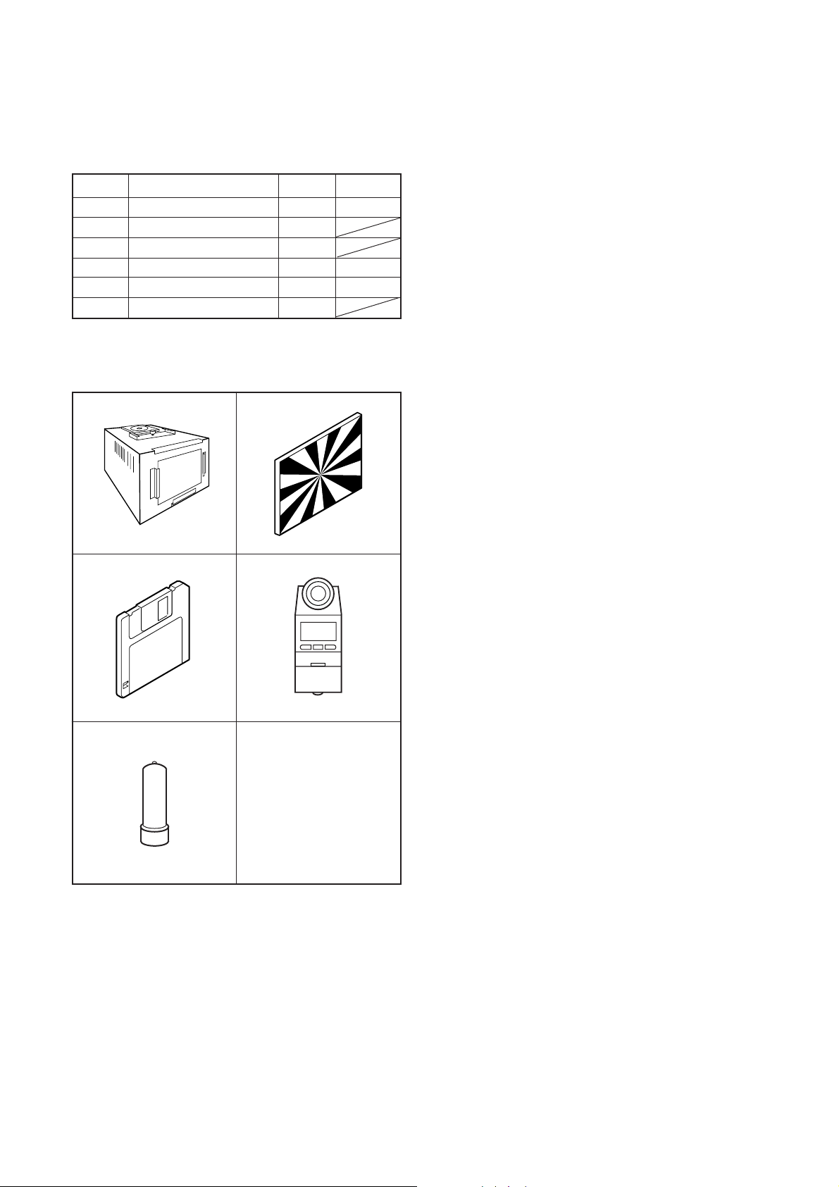
[1] Table for Servicing Tools
Ref. No.
J-1
J-2
J-3
J-4
J-5
J-6
Note: J-1 color viewer is 100 ± 10 VAC only.
Pattern box (color viewer)
Siemens star chart
Calibration software
Chroma meter
Spare lamp
Collimator
Use J-6 collimator made by Kyoritsu Electric Co. Ltd.
or equivalent of it.
Name Part code
Number
1
1
1
1
1
1
J-1 J-2
J-3
J-4
KC0336
KC0337
KC0339
[3] Adjustment Items and Order
1. AF LED Angle Adjustment
2. Lens Adjustment
3. AWB Adjustment
4. CCD White Point Defect Detect Adjustment
5. CCD Black And White Point Defect Detect Adjustment in
Lighted
Note:
1. If the lens, CCD, board and changing the part in item 1-
5 replace, it is necessary to adjust again. Item 4 and 5
should be carried out after item 3.
[4] Setup
1. System requirements
Windows 98SE or ME or 2000 or XP
IBM
® -compatible PC with pentium processor
CD-ROM drive, 3.5-inch high-density diskette drive
USB port, 40 MB RAM
Hard disk drive with at least 15 MB available
VGA or SVGA monitor with at least 256-color display
2. Installing calibration software
1. Insert the calibration software installation diskette into
your diskette drive.
2. Open Explorer.
3. Copy the DscCalDI_141 folder on the floppy disk in the
FD drive to a folder on the hard disk.
J-5
[2] Equipment
1. AC adaptor
2. PC (IBM
®-compatible PC, Pentium processor, Windows
98SE or ME or 2000 or XP)
3. Installing USB driver
Install the USB driver with camera or connection kit for PC.
4. Pattern box (color viewer)
Turn on the switch and wait for 30 minutes for aging to take
place before using Color Pure. It is used after adjusting the
chroma meter (KC0337) adjust color temperature to 3100
± 20 K and luminosity to 900 ± 20 cd/m
dling the lamp and its circumference are high temperature
during use and after power off for a while.
2
. Be careful of han-
C-2 Ver. 1
Page 3
C. ADJUSTMENT METHODC-70 ZOOM / C-7000 ZOOM
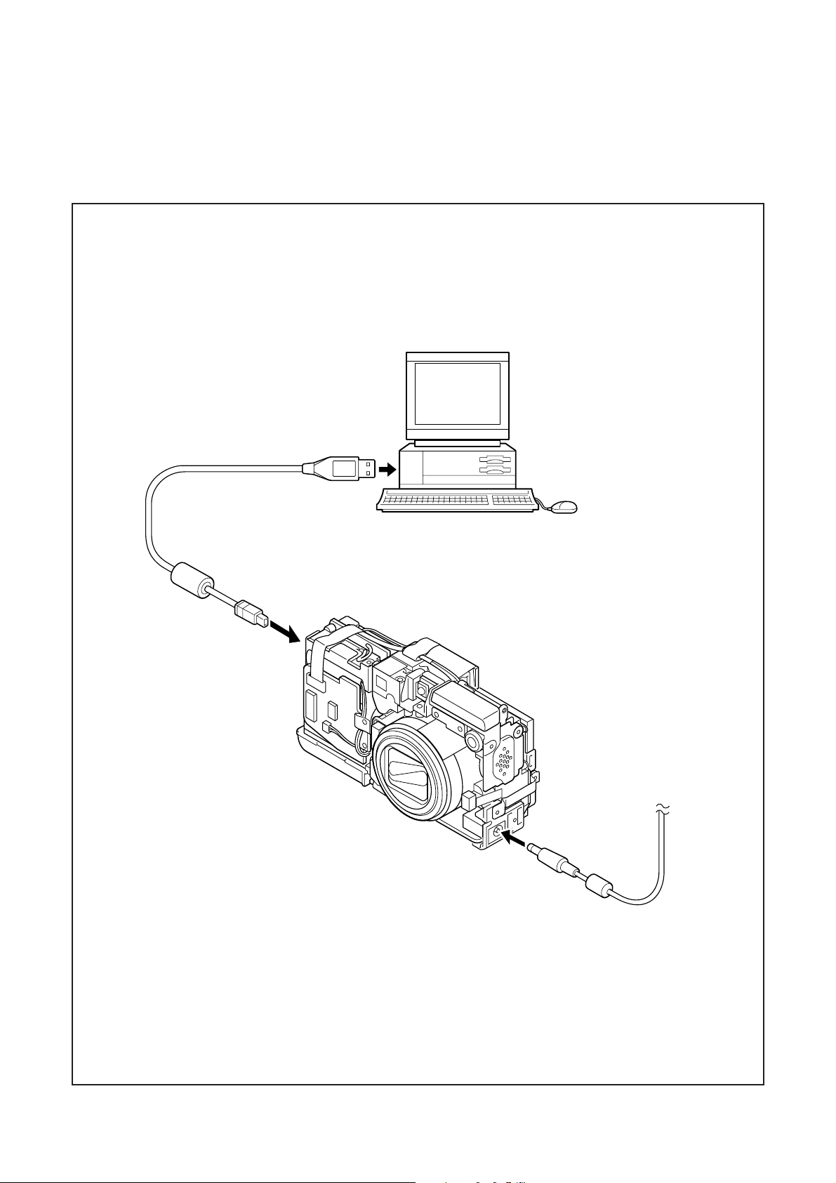
[5] Connecting the camera to the computer
1. Line up the arrow on the cable connector with the notch on the camera's USB port. Insert the connector.
2. Locate a USB port on your computer.
To USB port
USB cable
AC adaptor
C-3Ver. 1
Page 4

C. ADJUSTMENT METHOD C-70 ZOOM / C-7000 ZOOM
[6] USB Storage Information Registration
USB storage data is important for when the camera is connected to a computer via a USB connection.
If there are any errors in the USB storage data, or if it has
not been saved, the USB specification conditions will not be
satisfied, so always check and save the USB storage data.
Preparation:
POWER switch: ON
Adjustment method:
1. Connect the camera to a computer. (Refer to [5] Connecting the camera to the computer on the page C-3.)
2. Double-click on the DscCalDi.exe in the DscCalDi141.
3. Click on the Get button in the USB storage window and
check the USB storage data.
VID: OLYMPUS
PID: C70Z,C7000Z
Serial:
Rev. : 1.00
4. Check the "Serial" in the above USB storage data. If the
displayed value is different from the serial number printed
on the base of the camera, enter the number on the base
of the camera. Then click the Set button.
5. Next, check VID, PID and Rev. entries in the USB storage data. If any of them are different from the values in
3. above, make the changes and then click the corresponding Set button.
Calibration
AWB
Focus
UV Matrix
Cal Mode
Cal Data
USB storage
VID
Get
PID
Set
Backrush pulse :
OK
OK
Upload
Firmware
Data
PAF Cal.
EVF
LCD Type
Get
LCD
RGB Odd
RGB Gain
Tint
VCO
H AFC Test
Serial
Set
Set
Rev.
RGB Even
VCOMDC
Phase
Set
Set
Set
VCOMPP(LOW)
VCOMPP(HI)
Setting
Language
Video Mode
Factory Code
C-4 Ver. 1
Page 5

C. ADJUSTMENT METHODC-70 ZOOM / C-7000 ZOOM
t
[7] Adjust Specifications
1. AF LED Angle Adjustment
70 cm
70 cm
Target board
width
of 1cm
black
line
white
or gray
2. Lens Adjustment
Perform either the method A or the method B.
method A:
CAMERA
Collimeter
(Set up to the infinity.)
CAMERA
(T edge)
100 cm ± 0.5 cm
Siemens star char
Adjustment condition:
1. This adjustment should be carried out in a fairly dark
place so that the shape of the LED spot can be checked.
2. After adjustment, the readjustment is necessary to replace the lens, TB4 board and CA1 board.
3. Do not see the light of AF LED directly.
4. Do not adjust long time.
5. Remove the front cover
.
Adjustment method:
1.
Insert a xD-picture card in the camera.
2. Set the camera so that the target board is at a distance of
1 meters from LED. (Light up the target board.)
3. Turn on the power, double-click on the DscCalDi.exe.
4. Click the LCD "Test". Select the "AF LED" after select
"Monitor".
5. Carry out the pre-focus adjustment. After adjusting, the
target mark will appear on the LCD monitor.( )
6. Turn off the light of target board.
7. Turn the two screws in the TB4 board to adjust so that the
center of the LED spot appears inside the target mark on
the target board surface.
8.After adjusting, click the LCD "Test", and select the "OFF"S.
(The lens will be stowed.)
Preparation:
POWER switch: ON
Set up the collimator to the infinity.
Note:
Do not vibrate during the adjustment.
Either the collimator infinity adjustment or the 1 m adjustment can be used.
Adjustment method:
1. Set the camera so that it becomes center of the screen in
the collimator.
2. Double-click on the DscCalDi.exe.
3. Select "Infinity Cal." in the LCD "Test".
4. Infinity adjustment value will appear on the screen.
5. Set the siemens star chart is at a distance of 100 ± 0.5 cm
from the lens (T edge) so that it becomes center of the
screen. (A chart that is at least 1/4 the size of the screen
should be used at the W edge.)
6. Click the "Focus", and Click the "Yes".
7. 1 m adjustment value will appear on the screen.
8. Click the OK.
Adjustment value determination is effectuated using
"FOCUS_INF" (infinity adjustment) and "FOCUS_NEAR" (1
m adjustment) values.
FOCUS_INF=f1, f2, f3, f4, f5, FOCUS_NEAR=nf1, nf2, nf3,
nf4, nf5, and the adjustment values fulfill the conditions below, they are determined as within specifications.
Adjustment value determination
-70<f1<130, Ð80<f2<120, Ð90<f3<120, Ð60<f4<170,
-110<f5<330
-70<nf1<130, -80<nf2<120, -90<nf3<120, -60<nf4<170,
-110<nf5<330
C-5Ver. 1
Page 6

C. ADJUSTMENT METHOD C-70 ZOOM / C-7000 ZOOM
method B:
CAMERA
CAMERA
(T edge)
100 cm ± 0.5 cm
Siemens star chart
100 cm ± 0.5 cm
Siemens star chart
Adjustment value determination
-70<f1<130, -80<f2<120, -90<f3<120, -60<f4<170,
-110<f5<330
-70<nf1<130, -80<nf2<120, -90<nf3<120, -60<nf4<170,
-110<nf5<330
3. A WBAdjustment
Camera
Pattern box
(color viewer)
Preparation:
POWER switch: ON
Note:
Do not vibrate during the adjustment.
Carry out 2m adjustment after 1m adjustment.
Adjustment method:
1. Write the firmware for adjustment to the camera.
(Refer to update procedure)
Version : v852-78-LENSADJ
2. Double-click on the DscCalDi.exe.
3. Set the siemens star chart is at a distance of 100 ± 0.5 cm
from the lens (T edge) so that it becomes center of the
screen. (A chart that is at least 1/4 the size of the screen
should be used at the W edge.)
4. Click the "Focus", and Click the "Yes".
5. 1 m adjustment value will appear on the screen.
6. Click the OK.
7. Set the siemens star chart is at a distance of 200 ± 0.5 cm
from the lens (T edge) so that it becomes center of the
screen.
8. Select "Infinity Cal." in the LCD "Test".
9. 2 m adjustment value will appear on the screen.
10. Click the OK.
11. Rewrite the latest firmware for markets.
Adjustment value determination is effectuated using
"FOCUS_INF" (2m adjustment) and "FOCUS_NEAR" (1 m
adjustment) values.
FOCUS_INF=f1, f2, f3, f4, f5, FOCUS_NEAR=nf1, nf2, nf3,
nf4, nf5, and the adjustment values fulfill the conditions below, they are determined as within specifications.
Preparation:
POWER switch: ON
Setting of pattern box:
Color temperature: 3100 ± 20 (K)
Luminance: 900 ± 20 (cd/m
2
)
Adjusting method:
1. Set the camera 0 cm from the pattern box. (Do not enter
any light.)
2. Double-click on the DscCalDi.exe.
3. Click the "AWB", and click the "Yes".
4. AWB adjustment value will appear on the screen.
5. Click the OK.
Adjustment value determination is effectuated using "AGC"
and "CHECK" values.
If AGC=a1, a2, a3, a4, a5, CHECK=wc0, wc 1, wc2 and the
adjustment values fulfill the conditions below, they are determined as within specifications.
Adjustment value determination
a1<1023, a2<1023, a3<1023, a4<1023, a5<1023
wc0=128 ± 2, wc1=128 ± 2, wc2=130 ± 40
4. CCD White Point Defect Detect Adjustment
Preparation:
POWER switch: ON
Adjustment method:
1. Double-click on the DscCalDi.exe.
2. Select "CCD Defect" on the LCD "Test", and click the "Yes".
3. After the adjustment is completed, the number of defect
will appear.
(When adjustment is failed, "detect_ng" will display.)
4. Click the OK.
C-6 Ver. 1
Page 7

C. ADJUSTMENT METHODC-70 ZOOM / C-7000 ZOOM
5. CCD Black And White Point Defect Detect
Adjustment In Lighted
Camera
Pattern box
(color viewer)
Preparation:
POWER switch: ON
Setting of pattern box:
Color temperature: 3100 ± 20 (K)
Luminance: 900 ± 20 (cd/m
2
)
Adjusting method:
1. Set the camera 0 cm from the pattern box. (Do not enter
any light.)
2. Double-click on the DscCalDi.exe.
3. Select "CCD Black" on the LCD "Test", and click the "Yes".
4. After the adjustment is completed, the number of defect
will appear.
(When adjustment is failed, "detect_ng BLACK x, y" will
display.)
5. Click the OK.
Completing the adjustment mode
1. Open the card cover of the camera.
2. Turn on the power switch. "CARD-COVER OPEN" will be
displayed in the LCD.
3. Push the QUICKVIEW button and OK button more than 3
seconds simultaneously.
4. Push the right arrow button, and select "CONTROL".
5. "STORAGE/CONTROL" will be displayed.
6. Push the below arrow button, and select "STORAGE".
7. Push the OK button.
8. Close the card cover of the camera.
C-7Ver. 1
Page 8

C. ADJUSTMENT METHOD C-70 ZOOM / C-7000 ZOOM
C-8 Ver. 1
 Loading...