

Page 1

B. DISASSEMBLY AND ASSEMBLY PROCEDURE
X-300/D-565ZOOM/C-450ZOOM
B. DISASSEMBLY AND ASSEMBLY
PROCEDURE
[1] REMOVAL OF CABINET BACK, CABINET FRONT AND LCD .............................B-2
[2] REMOVAL OF SY1 BOARD, TB1BOARD AND CP1 BOARD ............................... B-3
[3] REMOVAL OF LENS UNIT, VIEWFINDER AND CA1BOARD ............................... B-3
[4] ASSEMBLY OF LENS UNIT AND VIEWFINDER.................................................... B-4
[5] BOARD LOCATION ................................................................................................ B-4
B-1 Ver.1
Page 2

B. DISASSEMBLY AND ASSEMBLY PROCEDURE X-300/D-565ZOOM/C-450ZOOM
[1] REMOVAL OF CABINET BACK, CABINET FRONT AND LCD
Disassembly perform as follows and assembly perform by reversing the disassembly steps.
Be sure to discharge the main capacitor, then continue to disassembling.
! Beware of electric shock
Danger of electric shock.
Use a discharging tool to remove
the electrical charge before working.
1. Open the cover USB.
2. Open the cover card
3. Four screws 1.7 x 4
4. Two screws 1.7 x 5
5. Screw 1.7 x 3.5
6. Cabinet back
7. Discharge both edge of C5412
8. Connector
9. FPC
10. LCD
The lead free solder is applied to this product.
!
11. Screw 1.7 x 4
12. Screw 1.7 x 5
13. Holder monitor
14. Three screws 1.7 x 5
15. Connector
16. Cabinet front
17. Cover jack
18. Stand
Use the lead free solder in working.
Notice
1
3
6
2
12
16
15
C5412
14
11
B
A
10
9
8
14
A
B
18
13
Discharge both edge of C5412.
7
(CP1 board side B)
C5412
3
3
5
4
17
B-2 Ver. 1
Page 3
B. DISASSEMBLY AND ASSEMBLY PROCEDUREX-300/D-565ZOOM/C-450ZOOM
black
white
yellow
white
yellow
black
1
2
3
4
5
5
6
6
7
8
9
10
9
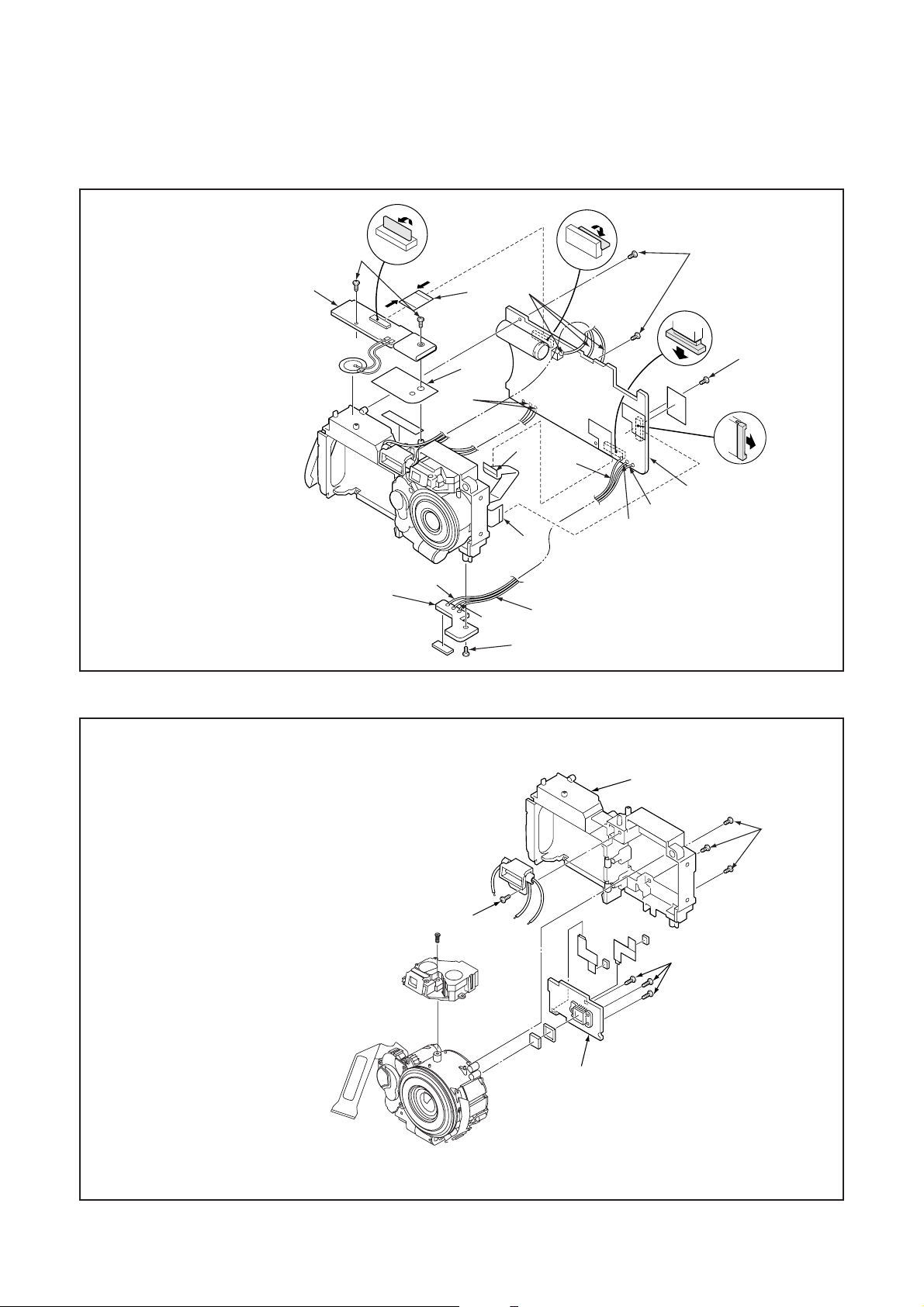
[2] REMOVAL OF SY1 BOARD, TB1 BOARD AND CP1 BOARD
1. Screw 1.7 x 3.5
2. FPC
3. SY1 board
4. Spacer flash
5. Three screws 1.7 x 3.5
6. Two FPCs
7. Screw 1.7 x 3.5
8. TB1 board
9. Remove the solder.
10. CP1 board
[3] REMOVAL OF LENS UNIT, VIEWFINDER AND CA1 BOARD
8
1. Three screws 1.6 x 5
2. Lens unit
3. Three screws 1.6 x 3.5
5. Screw 1.6 x 3.5
6. Viewfinder
7. Screws 1.7 x 3.5
8. Holder chassis
4. CA1 board
7
5
6
4
2
3
1
B-3 Ver. 1
Page 4
B. DISASSEMBLY AND ASSEMBLY PROCEDURE X-300/D-565ZOOM/C-450ZOOM
rd
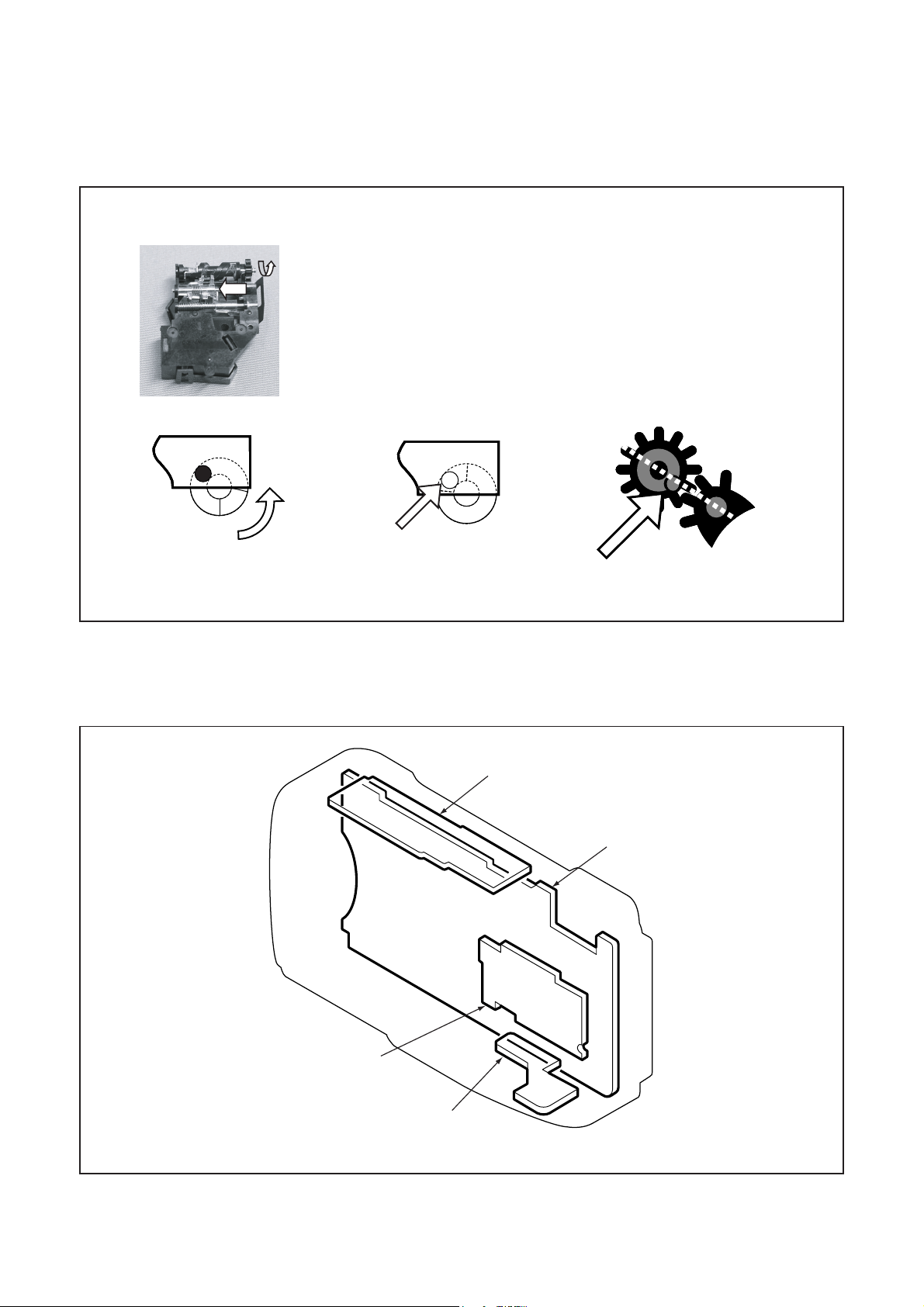
[4] ASSEMBLY OF LENS UNIT AND VIEWFINDER
1
1. Rotate F-Gear to move F-Lens to the set-down position.
2. Rotate F-Gear to the cut position.
3. Insert a pin to keep F-Cam position.
4. Set the Viewfinder to the Lens unit and tighten a screw.
5. Confirm the position of F-Gear and Idle-Gear.
2
Rotet F-Gear
Viewfinder (back side)
[5] BOARD LOCATION
3
Insert apin
Viewfinder (back side)
SY1 board
5
Viewfinder and Idle-Gear (front side)
CP1 boa
CA1 board
TB1 board
B-4 Ver. 1
 Loading...