

Page 1

C. ADJUSTMENT METHOD
C-3040 Zoom
C. ADJUSTMENT METHOD
[1] TABLE FOR SERVICING TOOLS .......................................................................... C-2
[2] EQUIPMENT ........................................................................................................... C-2
[3] ADJUSTMENT ITEMS AND ORDER ..................................................................... C-2
[4] SETUP ....................................................................................................................C-2
[5] CONNECTING THE CAMERA TO THE COMPUTER ............................................ C-3
[6] USB STORAGE INFORMATION REGISTRATION ................................................. C-4
[7] ADJUST SPECIFICATIONS ................................................................................... C-5
1. IC501 OSCILLATION FREQUENCY ADJUSTMENT ........................................ C-5
2. 5.1 V (A) VOLTAGE ADJUSTMENT................................................................... C-5
3. 13.0 V (L) VOLTAGE ADJUSTMENT ................................................................. C-5
4. 7.0 V (L) VOLTAGE ADJUSTMENT................................................................... C-5
5. LENS ADJUSTMENT ........................................................................................ C-5
6. AWB ADJUSTMENT .......................................................................................... C-6
7. COLOR MATRIX ADJUSTMENT .......................................................................C-6
8. CCD DEFECT DETECT ADJUSTMENT ........................................................... C-6
9. CCD BLACK POINT DEFECT ADJUSTMENT ................................................. C-6
10. LCD PANEL ADJUSTMENT ...........................................................................C-7
10-1. LCD H AFC ADJUSTMENT .....................................................................C-7
10-2. LCD GAIN ADJUSTMENT ....................................................................... C-7
10-3. LCD RGB OFFSET ADJUSTMENT ......................................................... C-7
10-4. LCD RED BRIGHTNESS ADJUSTMENT .............................................. C-7
10-5. LCD BLUE BRIGHTNESS ADJUSTMENT .............................................C-8
10-6. LCD TINT ADJUSTMENT (FOR PAL) .....................................................C-8
[8] ADJUST VALUES ................................................................................................... C-9
[9] ADJUST ITEMS ....................................................................................................C-10
SIMENS STAR CHART ................................................................................................. C-11
CHECKING OF LENS UNIT ..........................................................................................C-12
SERVER_DIS
C-1
Ver.1/Rev.3
Page 2
C. ADJUSTMENT METHOD C-3040 Zoom
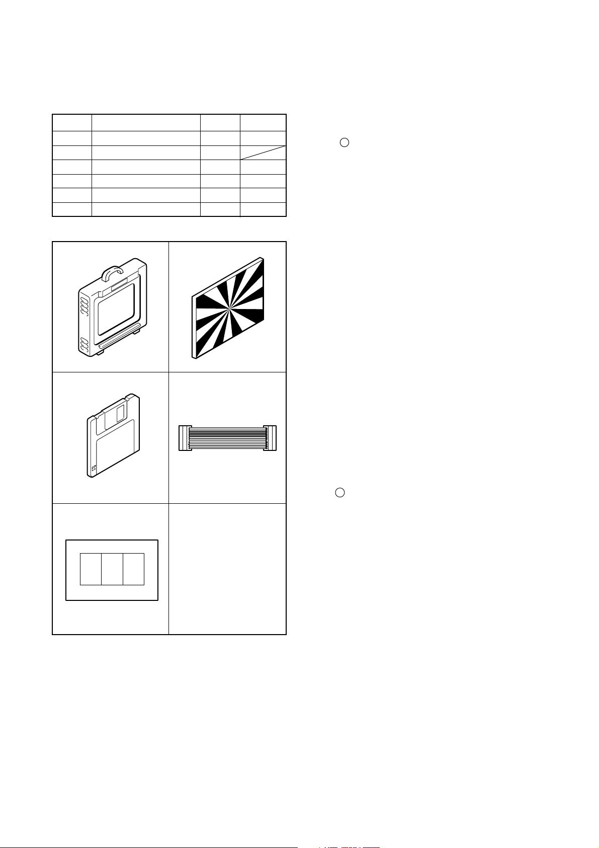
[1] Table for Servicing Tools
Ref. No. Name Part code
J-1
J-2
J-3
J-4
J-5 Extensioncord
J-6
Note: J-1 color viewer is 100 - 110 VAC only.
Color viewer 5,100 K
Siemens star chart
Calibration software
Extensioncord
Chart for color adjustment
(ST1/CA2)
(SY1/CA2)
Number
1
1
1
1
1
1
VJ8-0007
VJ8-0175
VJ8-0162
VJ8-0165
VJ8-0155
J-1 J-2
J-3
J-4/J-5
[2] Equipment
1. Oscilloscope
2. Digital voltmeter
3. AC adaptor
4. IBM R -compatible PC
5. DC regulated power supply
[3] Adjustment Items and Order
1. IC501 Oscillation Frequency Adjustment
2. 5.1 V (A) Voltage Adjustment
3. 13.0 V (L) Voltage Adjustment
4. 7.0 V (L) Voltage Adjustment
5. Lens Adjustment
6. AWB Adjustment
7. Color matrix Adjustment
8. CCD Defect Detect Adjustment
9. CCD Black Point Defect Detect Adjustment
10. LCD Panel Adjustment
10-1. LCD H AFC Adjustment
10-2. LCD Gain Adjustment
10-3. LCD RGB Offset Adjustment
10-4. LCD Red Brightness Adjustment
10-5. LCD Blue Brightness Adjustment
10-6. LCD Tint Adjustment (for PAL)
Note:
1. If the lens, CCD, board and changing the part in item 58 replace, it is necessary to adjust again. Item 6-8 adjustments should be carried out in sequence. Item 8 and
9 adjustments should be carried out after item 6.
J-6
[4] Setup
1. System requirements
Windows 95 or 98
IBM R -compatible PC with Pentium processor
CD-ROM drive
3.5-inch high-density diskette drive
Serial port with standard RS-232C interface or USB port
8 MB RAM
Hard disk drive with at least 15 MB available
VGA or SVGA monitor with at least 256-color display
2. Installing calibration software
1. Insert the calibration software installation diskette into
your diskette drive.
2. Open Explorer.
3. Copy the DSC Cal folder on the floppy disk in the FD
drive to a folder on the hard disk.
3. Installing USB drive
Install the USB drive with camera or connection kit for PC.
C-2 Ver.1SERVER_DIS
Page 3
C. ADJUSTMENT METHODC-3040 Zoom
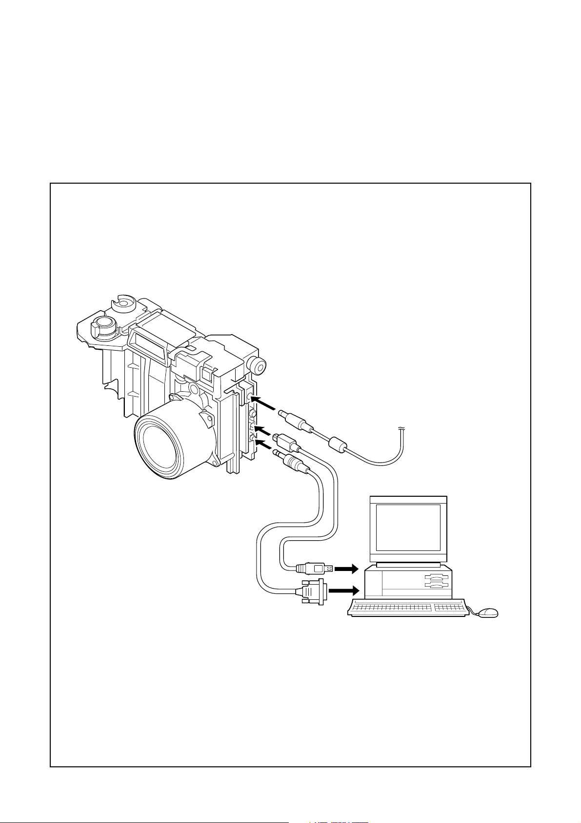
[5] Connecting the camera to the computer
1. Turn off both camera and computer.
2. Line up the arrow on the serial cable connector with the notch on the camera's serial port. Insert the connector.
In case of USB cable, line up the arrow on the USB cable connector with the notch on the camera's USB port. Insert the
connector.
3. Line up the serial connector on the serial cable with the serial port on your computer, and insert the connector.
In case of USB cable, line up the USB connector on the USB cable with the USB port on your computer, and insert the
connector.
4. Turn on the camera and your computer system.
Serial cable
To serial port or USB port
AC adaptor
USB cable
C-3Ver.1 SERVER_DIS
Page 4
C. ADJUSTMENT METHOD C-3040 Zoom
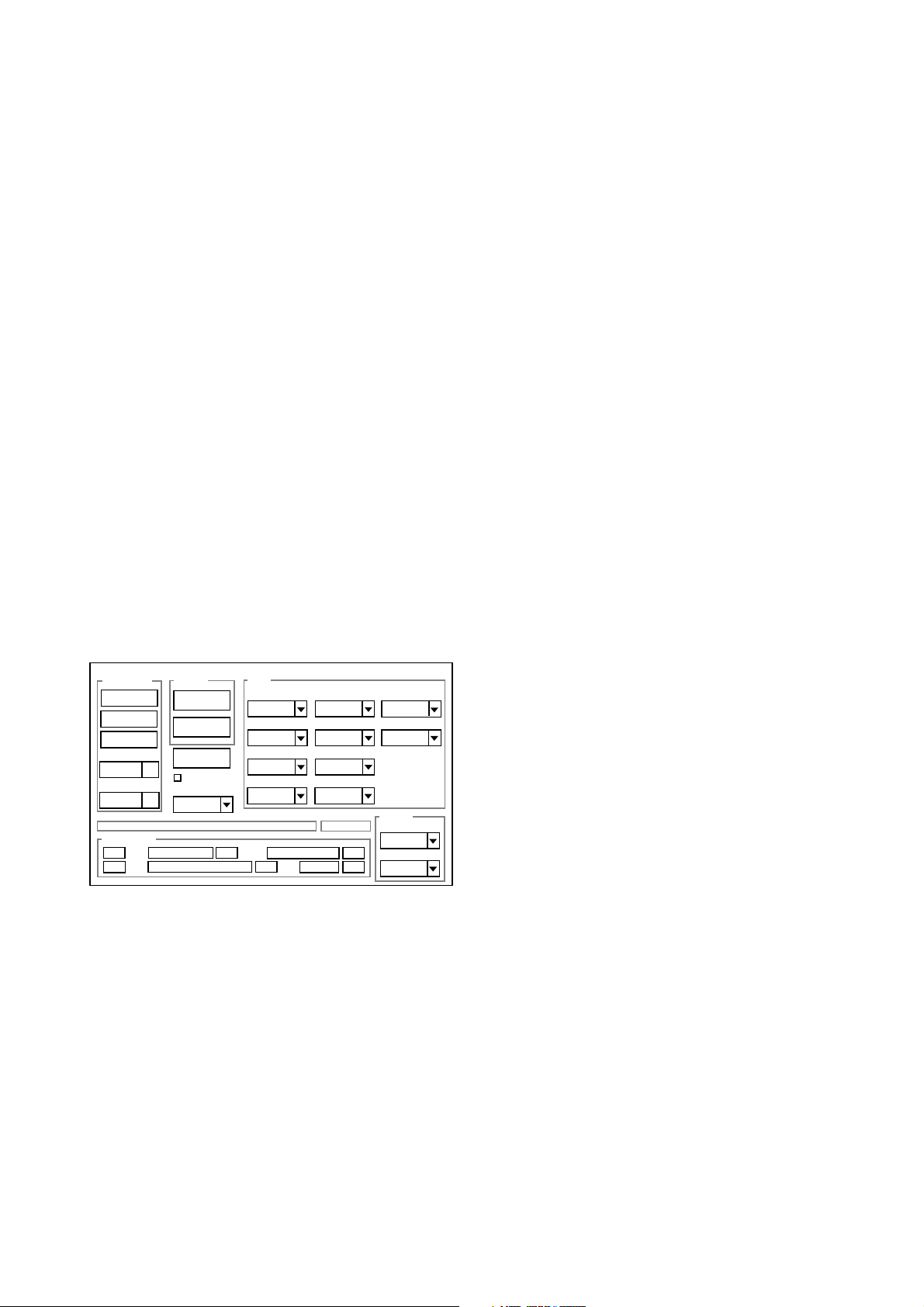
[6] USB STORAGE INFORMATION REGISTRATION
USB storage data is important for when the camera is connected to a computer via a USB connection.
If there are any errors in the USB storage data, or if it has
not been saved, the USB specification conditions will not
be satisfied, so always check and save the USB storage
data.
Preparation:
POWER switch: ON
Adjustment method:
1. Connect the camera to a computer. (Refer to [5] Connecting the camera to the computer on the page C-3.)
2. Double-click on the DscCalDi126.
3. Click on the Get button in the USB storage window and
check the USB storage data.
VID: OLYMPUS
PID: C-3040ZOOM
Serial:
Rev. : 1.00
4. Check the “Serial” in the above USB storage data. If
the displayed value is different from the serial number
printed on the base of the camera, enter the number
on the base of the camera. Then click the Set button.
5. Next, check VID, PID and Rev. entries in the USB storage data. If any of them are different from the values in
3. above, make the changes and then click the corresponding Set button.
Calibration
AWB
Focus
UV Matrix
Cal Mode
Cal Data
USB strage
VID
Get
PID
Set
OK
OK
Upload
Firmware
Image
Initialize
EVF
LCD Type
LCD
R Bright
RGB Offset
Tint
H AFC Test
Serial
Set
Set
Rev.
B Bright
Gain
Phase
Set
Set
VCOMDC
VCOMPP
Setting
Language
Video Mode
C-4 Ver.1SERVER_DIS
Page 5
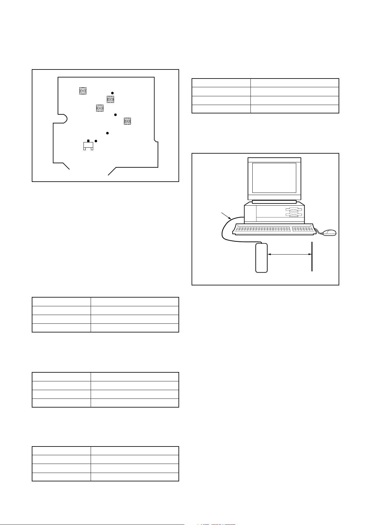
[7] Adjust Specifications
[ST1 board (Side B)]
C. ADJUSTMENT METHODC-3040 Zoom
Adjustment method:
1.Adjust with VR504 to 13.00 ± 0.05 V.
4. 7.0 V (L) Voltage Adjustment
VR501
CL524
(Side A)
VR504
VR502
CL566
VR505
CL522
CL501
(Side A)
Q5001
Collector
(Side A)
Note:
1. Voltage adjustment is necessary to repair in the ST1 board
and replace the parts.
2. Carry out adjustment with disconnect wires for storbe.
Preparation:
1. Connect the SY1 board (CN301) and the CA2 board
(CN106) with extension cord. (VJ8-0165)
2. Connect the ST1 board (CN501) and the CA2 board
(CN104) with extension cord. (VJ8-0162)
3. Connect LCD panel.
4. Insert the card.
5. Turn on the power switch, and then set the camera mode.
1. IC501 Oscillation Frequency Adjustment
Measuring Point
Measuring Equipment
ADJ. Location
ADJ. Value
Adjustment method:
1. Adjust with VR501 to 200 ± 1 kHz.
Q5001 Collector or CL501
Frequency counter
VR501
200 ± 1 kHz
2. 5.1 V (A) Voltage Adjustment
Measuring Point
Measuring Equipment
ADJ. Location
ADJ. Value
Adjustment method:
1. Adjust with VR502 to 5.10 ± 0.05 V.
CL524
Digital voltmeter
VR502
5.10 ± 0.05 V
3. 13.0 V (L) Voltage Adjustment
Measuring Point
Measuring Equipment
ADJ. Location
ADJ. Value
CL522
Digital voltmeter
VR504
13.00 ± 0.05 V
Measuring Point
Measuring Equipment
ADJ. Location
ADJ. Value
CL566
Digital voltmeter
VR505
7.00 ± 0.05 V
Adjustment method:
1. Adjust with VR505 to 7.00 ± 0.05 V.
5. Lens Adjustment
Serial cable
Camera
150 cm ± 3 cm
Siemens
star chart
Setting the adjustment mode
1. Open the card cover of the camera.
2. Push the menu button and LCD button more than 3 seconds simultaneously. Display “CAMERA CONTROL
OFF”.
3. Push the right arrow button and below arrow button, and
select “ON”.
4. Push the OK button twice.
5. Close the card cover of the camera.
Preparation:
POWER switch: ON
Adjustment condition:
Siemens star chart (A3)
Fluorescent light illumination with no flicker (incandescent
light cannot be used.)
Illumination above the subject should be 400 lux ± 10%.
Adjustment method:
1. Set the siemens star chart 150 cm ± 3 cm so that it becomes center of the screen.
2. Double-click on the DscCalDi126.
3. Click the “Focus”, and Click the “Yes”.
4. Lens adjustment value will appear on the screen.
5. Click the OK.
C-5Ver.1 SERVER_DIS
Page 6

C. ADJUSTMENT METHOD C-3040 Zoom
6. AWB Adjustment
Serial cable
Camera
All white pattern
Color viewer (5,100K)
Preparation:
POWER switch: ON
Adjusting method:
1. When setting the camera in place, set it to an angle so
that nothing appears in any part of the color viewer except the white section. (Do not enter any light.)
2. Double-click on the DscCalDi126.
3. Click the “AWB”, and click the “Yes”.
4. AWB adjustment value will appear on the screen.
5. Click the OK.
7. Color Matrix Adjustment
4. Click the “UV Matrix”, and Click the “Ye s”.
5. Adjustment values will appear on the screen.
6. Click the OK.
8. CCD Defect Detect Adjustment
Preparation:
POWER switch: ON
Adjustment method:
1. Double-click on the DscCalDi126.
2. Select “CCD Defect” on the LCD “Test”, and click the
“Yes”.
3. After the adjustment is completed, OK will display.
4. Click the OK.
9. CCD Black Point Defect Detect Adjustment
Serial cable
Camera
All white pattern
Color viewer (5,100K)
Serial cable
Camera
15 cm ± 1 cm
All white pattern color
viewer (5,100K) and
color matrix adjustment chart
Preparation:
POWER switch: ON
Adjustment method:
1. Set the color adjustment chart to the color viewer.
(Do not enter any light.)
2. Set the color adjustment chart so that it becomes center
of the screen.
3. Double-click on the DscCalDi126.
Preparation:
POWER switch: ON
Adjustment method:
1. When setting the camera in place, set it to an angle so
that nothing appears in any part of the color viewer except the white section.
2. Double-click on the DscCalDi126.
3. Select “CCD Black” on the LCD “Test”, and click the “Yes”.
4. After the adjustment is completed, OK will display.
5. Click the OK.
C-6 Ver.1SERVER_DIS
Page 7

10. LCD Panel Adjustment
[CA2 board (Side A)]
CL413
CL414
CL415
C. ADJUSTMENT METHODC-3040 Zoom
10-3. LCD RGB Offset Adjustment
Adjusting method:
1. Adjust LCD “RGB Offset” so that the amplitude of the
CL415 waveform is 4.6 V ± 0.1 Vp-p.
Note:
10-2. LCD Gain adjustment should always be carried out
first.
4.6V
±0.1Vp-p
CL415 waveform
10-1. LCD H AFC Adjustment
Preparation:
POWER switch: ON
Adjusting method:
1. Double-click on the DscCalDi126.
2. Select 0 on the LCD “H AFC”.
3. While watching the LCD monitor, adjust “H AFC” so that
the edge of the LCD adjustment frame are the same
distance from the left and right edge of the LCD screen.
(A = B)
LCD
LCD screen
A
FPC
adjustment
B
frame
10-2. LCD Gain Adjustment
Adjusting method:
1. Adjust LCD “Gain” so that the amplitude of the CL415
waveform is 1.0 V ± 0.1 Vp-p.
10-4. LCD Red Brightness Adjustment
Adjusting method:
1. Adjust LCD “R Bright” so that the amplitude of the CL414
waveform is VG± 0.1 Vp-p with respect to the CL415
(VG) waveform.
Note:
10-2. LCD Gain adjustment and 10-3. LCD RGB Offset adjustment should always be carried out first.
VG
CL415 waveform
VG±
0.1Vp-p
CL415 waveform
1.0V
±0.1Vp-p
CL414 waveform
C-7Ver.1 SERVER_DIS
Page 8

C. ADJUSTMENT METHOD C-3040 Zoom
10-5. LCD Blue Brightness Adjustment
Adjusting method:
1. Adjust LCD “B Bright” so that the amplitude of the CL413
waveform is VG ± 0.1 Vp-p with respect to the CL415
(VG) waveform.
Note:
10-2. LCD Gain adjustment and 10-3. LCD RGB Offset adjustment have done.
10-6. LCD Tint Adjustment (for PAL)
Adjusting method:
1. Adjust “Tint” so that the amplitude of CL415 waveform
is minimum.
Note:
10-6. LCD TINT adjustment should always be carried out
last.
a
CL415 waveform
CL413 waveform
VG
VG±
0.1Vp-p
a
a
a
Completing the adjustment mode
1. Open the card cover of the camera.
2. Push the menu button and LCD button more than 3 seconds simultaneously. Display “CAMERA CONTROL ON”.
3. Push the right arrow button and above arrow button, and
select “OFF”.
4. Push the OK button twice.
5. Close the card cover of the camera.
C-8 Ver.1SERVER_DIS
Page 9

C. ADJUSTMENT METHODC-3040 Zoom
[8 ] Adjustment Values
Explanation of adjustment values
Adjustment values are values which have been estimated
statistically from the distribution of adjustment values obtained from similar machine models and prototypes. Accordingly these values should be used as a guide only.
Because these values are guides, equipment which is in
good working order may still produce values which are outside the adjustment value ranges, so that the equipment
should be operated in order to determine whether it is in fact
operational or defective.
Range of adjustment values
(1) Lens adjustment ranges
(2) AWB adjustment ranges
[How to read a dialog of adjustment value]
“WD=WD1,WD2,WD3”
[Adjustment value]
STD_AFPOS : Within 15 and 120
Note :STD_AFPOS = “ 0 “ means NG.
[Adjustment value]
WD1: 200 to 400
WD2: 128(fixed value)
WD3: 200 to 400
(3) Color matrix adjustment ranges
[How to read a dialog of adjustment value]
“UD=UD0,UD1,UD2,UD3”
“UC=UC0,UC1,UC2,UC3”
[Adjustment value]
UD0: 40 to 160
UD1: 180 to 256, 0 to 60
UD2: 180 to 256, 0 to 60
UD3: 40 to 160
Adjustment values are normal except following cases.
It does not detect any signal from CCD. In this case,
adjustment values are all “1”.
UD0: 1
UD1: 1
UD2: 1
UD3: 1
C-9Ver.1 SERVER_DIS
Page 10

C. ADJUSTMENT METHOD C-3040 Zoom
[9] Adjustment Items
Adjustment items
1 IC501 Oscillation Frequency Adjustment
2 5.1V(A) Voltage Adjustment
3 13.0V(L) Voltage Adjustment
4 7.0V(L) Voltage Adjustment
5 Lens Adjustment
6 AWB Adjustment
7 Color Matrix Adjustmen
8 CCD Defect Detect Adjustment
9 CCD Black Point Detect Adjustment
10-1 LCD H AFC Adjustment
10-2 LCD Gain Adjustment
10-3 LCD RGB Offset Adjustment
10-4 LCD Red Brightness Adjustment
10-5 LCD Blue Brightness Adjustment
10-6 LCD Tint Adjustment (For PAL)
Changed repair parts
CCD
LENS CA1 ST1
CA2
¡
¡
¡
¡
¡¡¡ ¡
¡¡¡ ¡
¡¡¡ ¡
¡¡¡ ¡
¡¡¡ ¡
¡
¡
¡
¡
¡
¡
note)There is no need that you adjust the provided ST1when changing it without changing the parts of
component level.
C-10 Ver.1SERVER_DIS
Page 11

C. ADJUSTMENT METHODC-3040 Zoom
C-11Ver.1 SERVER_DIS
Page 12

CHECKING OF LENS UNIT
1. Check Item
1)Backlash Pulse of LD
2)LD ERROR Pulse
3)Basklash Pulse of ZOOM
4)ZOOM ERROR Pulse
2. Tools
Part No.
1
2
3
4
5
KC0331
KC0334
KC0338
FPC-Adaptor
FPC-Adaptor
C.ADJUSTMENT METHOD
Description
Lens Checker LCK1
Connector Cable P5
Clip Connector 17
14-PINS for K-FPC
16-PINS for S-FPC
Q’ty
1
1
2
1
1
C-3040ZOOM
FPC-Adaptor 14
PINS for K-FPC
FPC-Adaptor 16
PINS for S-FPC
The last 2 digits are mean-
ing the number of Pin.
080-10
3. Checking Prosedure
Fi x 2 FPC-Adaptors (14 and 16 PINS) to ClipConnector
17.
Connect Connector Cable P5, Clip Connector 17
and Lens Checker LCK-1
1) AUTO
I. Tum on Lens Checker LCK-1
Ex.) 080-14 :14PINS
Lens Checker LCK-1
Connector Cable P5
Initial Setting
II. Set AUTO / MANU SW at AUTO
III.Set Dial SW at 5
IV. Set CW / CCW SW at CW
LCK-1 Ver.1 0 Auto
PUSH START SW
(0 : Number of Dial SW 0-5)
V. Connect the both FPCs (K-FPC and S-FPC) to
Clip Connectors. Hold a lens unit by hand, and keep
it horizontally.
VI. Push START SW. (More than 0.2 sec.)
LCK-1 Ver.1 0 Auto
ZOOM RESET
Clip Connector 17
C-12 Ver. 1/Rev.3
Page 13

C-3040ZOOM C.ADJUSTMENT METHOD
When an error occurs, an error is indicated, and it stops.
LCK-1 Ver.1 0 Auto
LD RESET
LCK-1 Ver.1 0 Auto
LD BACKLASH CHK
LB*
* is BACKLASH PULSE of LD
LCK-1 Ver.1 0 Auto
LD D CHK
LB1 D *
* is LD ERROR PULSE
LCK-1 Ver.1 0 Auto
ZOOM BACKLASH CHK
LB1 D1 ZB *
* is BACKLASH PLUSE of ZOOM
In case of GOOD
LCK-1 Ver.1 0 Auto
PUSH START SW
LB1 D1 ZB1 D12
GOOD
In case of NG :
LCK-1 Ver.1 0 Auto
PUSH START SW
LB D6
NO GOOD ZM D Err
ERROR is indicated
(The indication which isn’t being explained is the condition
of PR and PI.)
When CW/CCW SW is set at CCW, the automatic check of
the motor chosen with a LD/ZOOM SW is done.
2) Manual
I. Set AUTO/MANU SW at MANU
LCK-1 Ver.1 0 Manu
LD CW
LCK-1 Ver.1 0 Auto
ZOOM D CHK
LB1 D1 ZB1 D * *
* * is ZOOM ERROR PULSE (ZOOM AREA : SET-UP AREA)
The contents chosen with the LD/ZOOM SW and the CW/
CCW SW indicated in LCD.
II. Push START SW (More than 0.2 sec.)
LCK- Ver.1 0 Manu
LD CW
MOVE
When a motor works, “MOVE” is indicated in LCD.
C-13Ver. 1/Rev.3
Page 14

C.ADJUSTMENT METHOD
LD Motor
When PI signal 500 pulses (500pps) are changed,LD motor
stops
CW : Turn Out CCW : Tum In
ZOOM Motor
When PI signal 2200 pulses (300pps) are changed, ZOOM
motor stops
CW : W to T CCW : T to W
4. Others
Turn off LCK-1 promptly if something is wrong.
5, ERROR Indication
PI, PR Err : PI or PR Pulse does not change.
LD BK Err : LD BACKLASH PULSE is out of standard.
LD D Err : LD Pulse Error
ZD BK Err : ZOOM BACKLASH PULSE is out of
standard
ZD D Err : ZOOM Pulse Error
C-3040ZOOM
C-14 Ver. 1/Rev.3
 Loading...