

Page 1

C-170/D-425
B. DISASSEMBLY AND ASSEMBLY PROCEDURE
[1] REMOVAL OF CABI BACK AND CABI FRONT ..........................................................B-2
[2] REMOVAL OF COVER LENS AND TB1 BOARD........................................................ B-3
[3] REMOVAL OF ST1 BOARD, CP1 BOARD AND LCD .................................................B-4
[4] REMOVAL OF LENS(ASSY) ........................................................................................B-5
[5] REMOVAL OF HOLDER CHASSIS ............................................................................. B-6
[6] BOARD LOCATION ...................................................................................................... B-7
B-1 Ver.1
Page 2
B. DISASSEMBL YAND ASSEMBLYPROCEDURE C-170/D-425
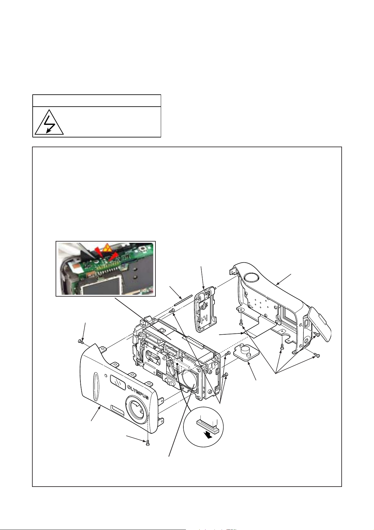
[1] REMOV AL OF CABI BACK AND CABI FRONT
Disassembly perform as follows and assembly perform by reversing the disassembly steps.
Be sure to discharge the main capacitor, then continue to disassembling.
! Beware of electric shock !
Danger of electric shock.
Use a discharging tool to remove
the electrical charge before working.
1. Six screws 1.7 x 4
2. Cabi back
3. FPC
4. Discharge C5412
5. Stand
6. Shaft strap
7. Cover battery
8. Three screws 1.7 x 4
9. Cabi front
4
6
When assembling,
tighten the screws order.
a => b => c => d => e => f
2
5
1
d
A
c
3
e
B
b
f
C
1
4
When assembling,
7
8
CN301
tighten the screws order.
A => B => C
1
a
Attach the barrier which attached to the main
part at the time of the Cabinet front attachment in the state where it opened.
B-2 Ver. 1
Page 3
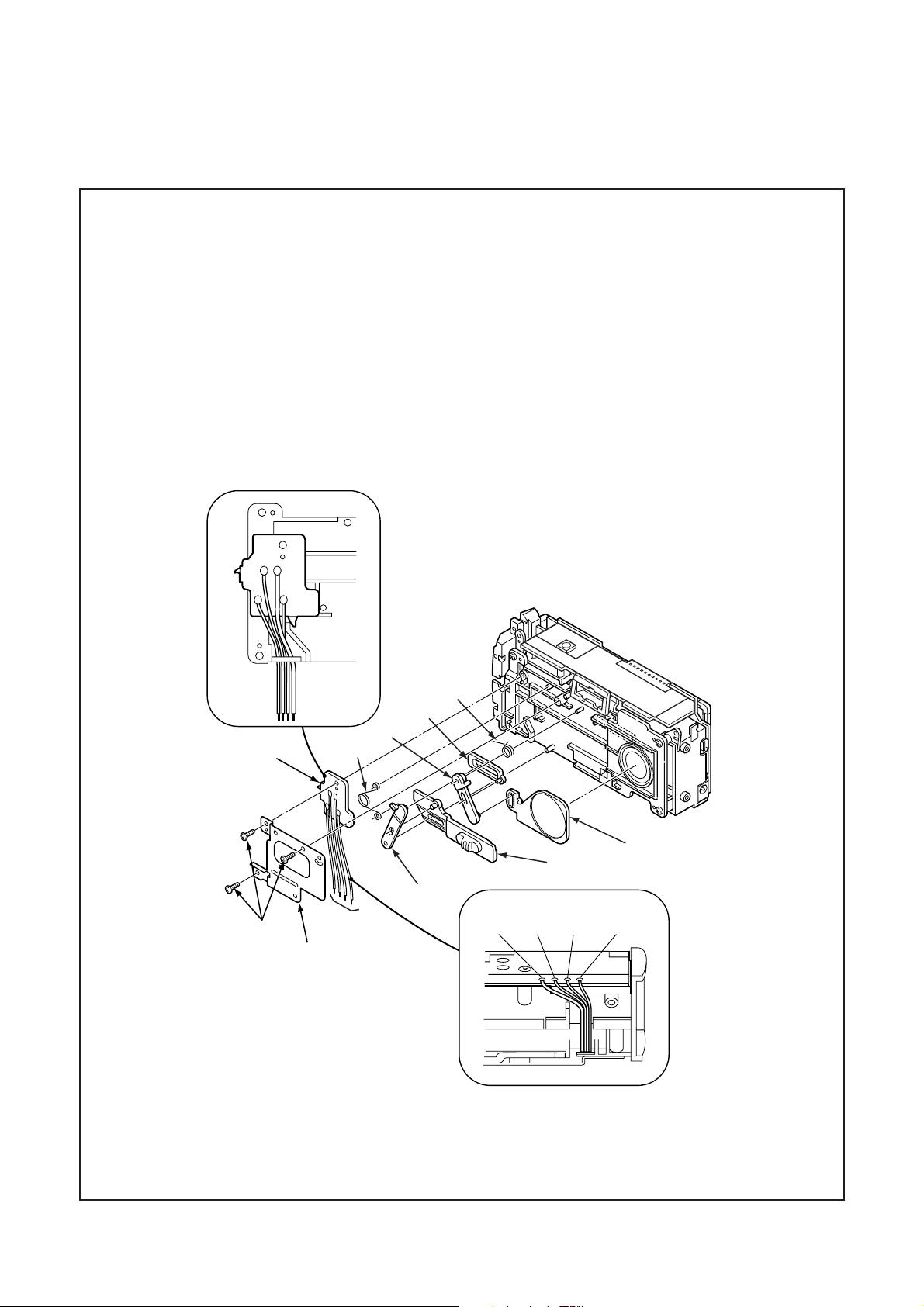
B. DISASSEMBL YAND ASSEMBLYPROCEDUREC-170/D-425
[2] REMOV AL OF COVER LENS AND TB1 BOARD
1. Remove the solder.
2. Three screws 1.7 x 4
3. Holder cover lens
4. Spring cover lens A
5. Lever cover lens A
6. Lever cover lens B
BK
GY
WH
RD
11
7. Spring cover lens B
8. Slide cover lens
9. Cover lens
10. Knob cover lens
1 1. TB1 board
7
8
6
4
9
10
5
1
2
BLACK RED GRAY WHITE
3
B-3 Ver. 1
Page 4
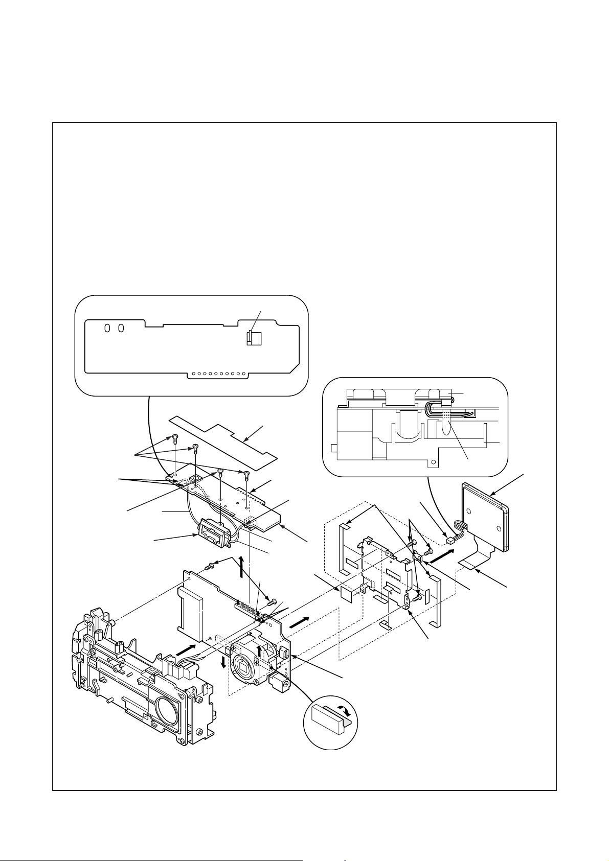
B. DISASSEMBL YAND ASSEMBLYPROCEDURE C-170/D-425
[3] REMOV ALOF ST1 BOARD , LCD AND CP1 BOARD
1. Spacer ST1
2. Remove the solder.
3. Three screws 1.7 x 4
4. ST1 board
5. Remove the solder.
6. Screw 1.7 x 3
7. Assy lamp
W1400
When assembling,
tighten the screws
order. a => b => c
PINK
W1500
BLUE
5
6
8. Remove the solder.
9. Spacer LCD
10. Three screws 1.7 x 4
1 1. Earth unit
12. Two screws 1.7 x 4
13. FPC
GRAY
T5402
CN541
14. Connector
15. LCD
16. Spacer monitorA
17. Holder monitor
18. Remove the solder.
19. CP1 board
LCD
1
a
3
PINK
b
c
CN541
BOSS
2
8
9
14
15
10
7
When assembling,
tighten the screws order.
A => B
A
CN172
12
CN101
BLUE
GY
(BAT)
B
GRAY
4
c
a
16
PK
(BAT+)
18
b
11
17
19
CN171
B-4 Ver. 1
When assembling,
tighten the screws order.
a => b => c
13
Page 5

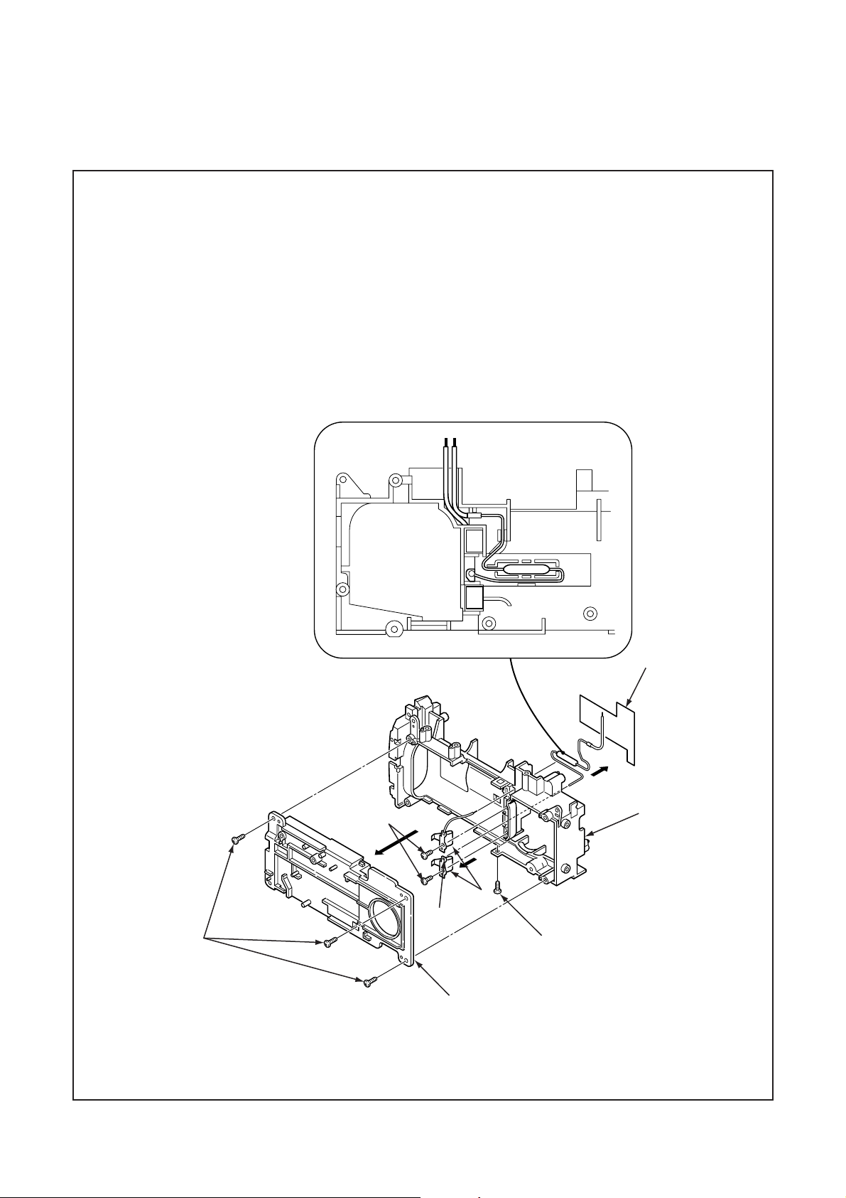
[4] REMOV AL OF LENS(ASSY)
1. Two screws 1.4 x 3.5
2. Remove the solder.
3. Three screws 1.4 x 3
4. FPC
5. Assy lens
B. DISASSEMBL Y AND ASSEMBLY PROCEDUREC-170/D-425
1
2
CN951
3
5
4
B-5 Ver. 1
Page 6
B. DISASSEMBL YAND ASSEMBLYPROCEDURE C-170/D-425
[5] REMOV AL OF HOLDER CHASSIS
1. Four screws 1.7 x 4
2. Holder front
3. Remove the solder.
4. Spacer fuse
5. Two screws 1.7 x 3
6. Two terminal batteries
7. Holder chassis
GYPK
4
5
7
6
3
1
1
2
B-6 Ver. 1
Page 7
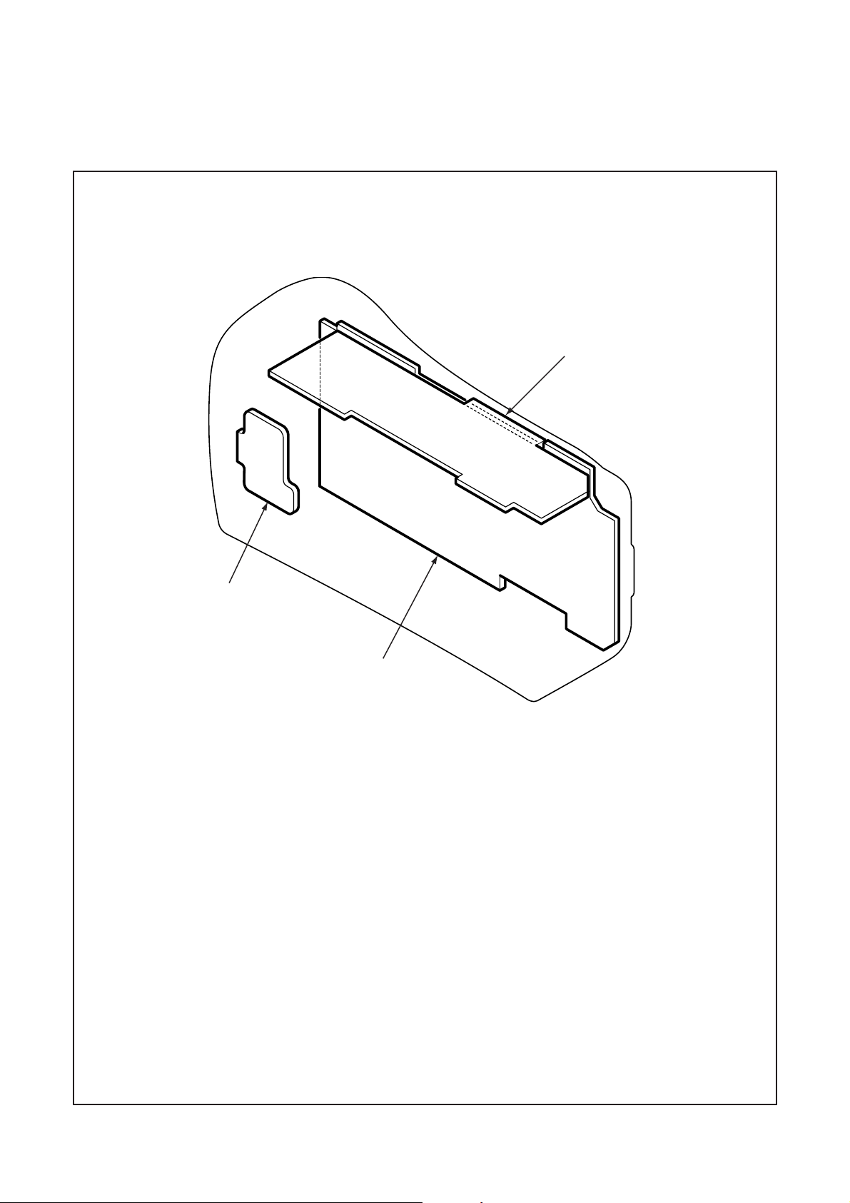
[6] BOARD LOCA TION
B. DISASSEMBL Y AND ASSEMBLY PROCEDUREC-170/D-425
ST1 board
TB1 board
CP1 board
B-7 Ver. 1
 Loading...