

Page 1

C-170 / D-425
C. ADJUSTMENT METHOD
[1] TABLE FOR SERVICING TOOLS................................................................................C-2
[2] EQUIPMENT.................................................................................................................C-2
[3] ADJUSTMENT ITEMS AND ORDER ...........................................................................C-2
[4] SETUP ........................................................................................................................................C-2
[5] CONNECTING THE CAMERA TO THE COMPUTER .................................................C-3
[6] USB STRAGE INFORMATION REGISTRA TION.........................................................C-4
[7] ADJUST SPECIFICATIONS.........................................................................................C-4
1. LENS ADJUSTMENT................................................................................................C-4
2. AWB ADJUSTMENT ......................................................................................................C-5
3. CCD WHITE POINT DEFECT DETECT ADJUSTMENT..........................................C-5
4. CCD BLACK AND WHITE POINT DEFECT DETECT ADJUSTMENT....................C-5
5. TRACKING ADJUSTMENT .............................................................................................. C-6
C-1 V e r.1
Page 2
C. ADJUSTMENT METHOD D-425(U)/C-170(E)
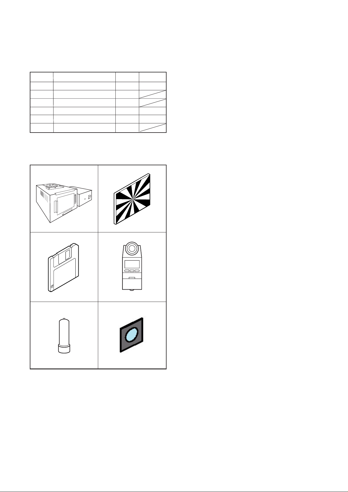
[1] T able for Servicing Tools
Ref. No.
J-1
J-2
J-3
J-4
J-5
J-6
J-6 : KC0429 with MC-C4 filter layered.
Note: J-1 color viewer is 100 ± 10 VAC only.
Pattern box (color viewer)
Siemens star chart
Calibration software
Chroma meter
Spare lamp
MC filter (with holder)
Name Part code
Number
1
1
1
1
1
1
J-1 J-2
J-3
J-4
KC0336
KC0337
KC0339
[3] Adjustment Items and Order
1. Lens Adjustment
2. AWB Adjustment
3. CCD White Point Defect Detect Adjustment
4. CCD Black And White Point Defect Detect Adjustment in
Lighted
5.Tracking Adjustment
Note:
1. If the lens, CCD, board and changing the part in item 2-
5 replace, it is necessary to adjust again. Item 4 and 5
should be carried out after item 3.
[4] Setup
1. System requirements
Windows® 98SE or ME or 2000 or XP
IBM®-compatible PC with pentium processor
CD-ROM drive, 3.5-inch high-density diskette drive
USB port, 40 MB RAM
Hard disk drive with at least 15 MB available
VGA or SVGA monitor with at least 256-color display
2. Installing calibration software
1. Insert the calibration software installation diskette into
your diskette drive.
2. Open Explorer.
3. Copy the DscCalDI_141 folder on the floppy disk in the
FD drive to a folder on the hard disk.
J-5
[2] Equipment
1. USB Cable
2. AC adaptor (E-8AC)
3. PC (IBM
dows®98SE or ME or 2000 or XP)
®-compatible PC, Pentium processor, Win-
J-6
3. Installing USB driver
Install the USB driver with camera or connection kit for PC.
4. Pattern box (color viewer)
Turn on the switch and wait for 30 minutes for aging to take
place before using Color Pure. It is used after adjusting the
chroma meter (KC0337) adjust color temperature to 3100
± 20 K and luminosity to 900 ± 20 cd/m
dling the lamp and its circumference are high temperature
during use and after power off for a while.
2
. Be careful of han-
C-2 Ver. 1
Page 3

C. ADJUSTMENT METHODD-425(U)/C-170(E)
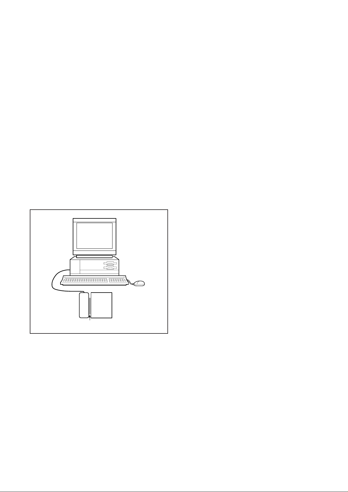
[5] Connecting the camera to the computer
1. Line up the arrow on the cable connector with the notch on the camera's USB port. Insert the connector.
2. Locate a USB port on your computer.
To USB port
USB cable
AC adaptor
C-3 Ver. 1
Page 4

C. ADJUSTMENT METHOD D-425(U)/C-170(E)
ns
rt
[6] USB Storage Information Registration
USB storage data is important for when the camera is connected to a computer via a USB connection.
If there are any errors in the USB storage data, or if it has
not been saved, the USB specification conditions will not be
satisfied, so always check and save the USB storage data.
Preparation:
POWER switch: ON
Adjustment method:
1. Connect the camera to a computer. (Refer to [5] Connecting the camera to the computer on the page C-3.)
2. Double-click on the DscCalDi.exe in the DscCalDi141.
3. Click on the Get button in the USB storage window and
check the USB storage data.
VID: OLYMPUS
PID: C170/D425
Serial:
Rev. : 1.00
4. Check the Serial in the above USB storage data. If the
displayed value is different from the serial number printed
on the base of the camera, enter the number on the base
of the camera. Then click the Set button.
5. Next, check VID, PID and Rev. entries in the USB storage data. If any of them are different from the values in
3. above, make the changes and then click the corresponding Set button.
Calibration
AWB
Focus
UV Matrix
Cal Mode
Cal Data
USB storage
VID
Get
PID
Set
Backrush pulse :
OK
OK
Upload
Firmware
Data
PAF Cal.
EVF
LCD Type
Get
LCD
R Bright
RGB Offset
Tint
VCO
H AFC Test
Serial
Set
Set
Rev.
B Bright
Gain
Phase
Set
Set
Set
VCOMDC
VCOMPP
Setting
Language
Video Mode
Factory Code
[7] Adjust Specifications
1. Lens Adjustment
Camera
from CCD surface
78~80 cm
from lens surface
76~78 cm
Preparation:
POWER switch: ON
Adjustment condition:
Siemens star chart (A3)
Fluorescent light illumination with no flicker (incandescent light
cannot be used.)
Illumination above the subject should be 700 lux ± 10%.
Adjustment method:
1. Set the siemens star chart 78 ~ 80 cm from CCD surface
(76 ~ 78 cm from lens surface) so that it becomes center
of the screen.
2. Double-click on the DscCalDi.exe.
3. Click "Focus", and Click "Yes".
4. Lens adjustment value will appear on the screen.
(When the adjustment is failed, "NG: AF X" will be displayed.)
5. Click "OK".
Adjustment value determination is effectuated using below values.
The adjustment values fulfill the conditions below, they are determined as within specifications.
Adjustment value determination
AF_SW: Y
Y: adjustment value of focus PI switch position
(930<=Y<=1070)
AF_WIDE: W
W: adjustment value of focus at Wide edge
(W=0)
Sieme
star cha
C-4 Ver. 1
Page 5

C. ADJUSTMENT METHODD-425(U)/C-170(E)
2. AWB Adjustment
Camera
Pattern box
(color viewer)
Preparation:
POWER switch: ON
Setting of pattern box:
Color temperature: 3100 ± 20 (K)
Luminance: 900 ± 20 (cd/m
Adjusting method:
1. Set the camera 0 cm from the pattern box. (Shield from
surrounding light.)
2. Double-click on the DscCalDi.exe.
3. Click "AWB", and click "Yes".
4. AWB adjustment value will appear on the screen.
5. Click "OK".
Adjustment value determination is effectuated using "AGC" and
"CHECK"
values.
If AGC=a1, a2, a3, a4, CHECK=wc0, wc1, wc2 and the adjustment values fulfill the conditions below, they are determined
as within specifications.
Adjustment value determination
a1<1023, a2<1023, a3<1023, a4<1023
wc0=128 ± 2, wc1=128 ± 2, wc2=130 ± 40
2
)
4. CCD Black And White Point Defect Detect
Adjustment In Lighted
Preparation:
POWER switch: ON
Setting of pattern box:
Color temperature: 3100 ± 20 (K)
Luminance: 900 ± 20 (cd/m
Adjusting method:
1. Set the camera 0 cm from the pattern box. (Shield from
surrounding light.)
2. Double-click on the DscCalDi.exe.
3. Select "CCD Black" on LCD- "Test", and click "Yes".
4. After the adjustment is complete, the number of defect
will be displayed.
(When adjustment is failed, "detect_ng BLACK x, y" will be
displayed.)
5. Click "OK".
Camera
Pattern box
(color viewer)
2
)
3. CCD White Point Defect Detect Adjustment
Preparation:
POWER switch: ON
Adjustment method:
1. Double-click on the DscCalDi.exe.
2. Select "CCD Defect" on LCD- "Test", and click "Yes".
3. After the adjustment is completed, the number of defect
will appear.
(When adjustment is failed, "detect_ng" will be displayed.)
4. Click "OK".
C-5 Ver. 1
Page 6
C. ADJUSTMENT METHOD D-425(U)/C-170(E)
5.Tracking Adjustment
Preparation:
POWER switch: ON
Setting of pattern box:
Color temperature: 3100 ± 20 (K)
Luminance: 900 ± 20 (cd/m
Color conversion filter: Pile C12 on C4
C4 filter should be purchased newly from market.
Note:
Wait more than 10 minutes when carry out the tracking adjustment again.
Adjusting method:
1. Set the color conversion filters between the camera and
the pattern box. (Shield from surrounding light.)
2. Double-click on the DscCalDi.exe.
3. Select "Tracking Adj" on the LCD- "Test".
4. Af ter the adjustment is complete, the adjustment value
will be diaplayed.
5. Click "OK".
2
)
Camera
Pattern box
(color viewer)
Color conversion filter
C-6 Ver. 1
 Loading...