


MACTURN 350
MACTURN 350-W
OPERATION & MAINTENANCE
(1st Edition)
Pub No. 6097-E (LE11-240-R1) Oct. 2012

6097-E P-(i)
SAFETY PRECAUTIONS
SAFETY PRECAUTIONS
The machine is equipped with safety devices which serve to protect personnel and the machine itself from
hazards arising from unforeseen accidents. However, operators must not rely exclusively on these safety
devices: they must also become fully familiar with the safety guidelines presented below to ensure accidentfree operation.
This instruction manual and the warning signs attached to the machine cover only those hazards which
Okuma can predict. Be aware that they do not cover all possible hazards.
1. Moving and Installing the Machine
• There are three methods of moving the machine to any desired location; lifting the machine
using the attached lifting hooks, pushing the machine on rollers, and moving with a forklift
truck. Perform any of them with following precautions below.
Precautions for Lifting:
a. Use the wire rope of 24 mm (0.94 in.) or over in diameter.
b. Check the wire rope angles so that the ropes do not interfere with the machine.
(Do not slant the machine more than 40 degrees from the vertical.)
c. Lift the machine carefully while balancing the machine.
d. When placing the machine on the floor, lower the machine slowly using care not to give
shocks to the machine.
Approximate Machine Mass
13,700 kg (30,140 lb) (44-tool magazine)
(Machine weight including hydraulic unit, control cabinet, NC unit, and tool magazine)
Precautions for Rolling
a. Do not tip over or hit the machine against the ground.
Notes on forklift :
a. Watch the lower surface of the machine when you move it by forklift and treat with care so
as not to damage the jack bolts or rotary joints with the forklift forks.
The machine may come out of the bottom surface of the bed, depending on its
specification.
LE11240R0100100020001

6097-E P-(ii)
SAFETY PRECAUTIONS
• When selecting the machine installation site, ensure that the following conditions are met.
If not, it may be difficult to perform safe operation or maintain the guaranteed accuracy.
a. The machine ambient temperature is within the range from 5 to 40°C (41 to 104°F).
b. The machine ambient humidity is within the range from 40 to 75% at 20°C and no
condensation is allowed.
c. Avoid installation near the factory door because the machine is subject to rapid
temperature change by warm or cool air blowing against the machine.
d. Also avoid installation in a place which is subject to direct sunlight.
e. For the installation ground conditions, refer to Section 2 “Transportation and Installation
(Relocation).”
f. To maintain the guaranteed accuracy, you are advised to care and control the factory
temperature.
Recommended temperature change for 24 hours: : Within ±2°C (36°F)
Temperature difference between the measurement near
the floor and the measurement at a position 3 m (10 ft.)
high from the floor
: Within 1°C (34°F)
2. Before Turning on the Power
• Make sure that the doors to the operation panel and the electric control cabinet are closed.
• Make sure that there are no obstacles around the machine.
• Turn on the main power disconnect switch before turning on the CONTROL on the operation
panel.

3. Chuck Precautions
• Always close the front shield before starting the spindle or cutting operations.
• Always observe the spindle speed maximums for the installed chuck.
Never run the spindle exceeding the maximum allowable chuck speed.
• If a chuck or fixture is unique to your application, check the maximum allowable spindle speed
and stay within the limit. Also, take note of the workpiece gripping force and balance.
• The maximum spindle speed can be limited by inputting a G50 command with the spindle
speed. The G50 command helps to ensure safety in operation.
• If the spindle must be rotated close to the maximum allowable chuck speed, observe the
following points:
The maximum allowable spindle speed and application pressure are indicated on the name
plate on the front shield and on the chuck body. The allowable maximum speed and the
applicable pressure ensure a chucking force that is more than one-third of the original chuck
gripping force with the standard soft-top jaw set in line with the periphery of the chuck body.
a. Make sure that the workpiece clamped in the chuck is balanced.
6097-E P-(iii)
SAFETY PRECAUTIONS
b. Apply the allowable maximum amount of pressure to grip the workpiece because
centrifugal force reduces the chuck gripping force.
• If special jaws (larger than standard soft-top jaws) are used, observe the following points:
a. Lower the spindle speed because centrifugal force and lower efficiency reduce the chuck
gripping force.
b. If the jaw tightening nut (jaw nut) is outside of the periphery of the chuck, only one
tightening bolt is holding the jaws in place. This is a potentially dangerous condition. Jaw
nuts must always be within the periphery of the chuck.
c. Machine the jaws to the workpiece shape.
• Securely tighten the bolts on the chuck body, the jaws, and the block to the specified torque.
Use lubrication oil. Make sure that the torque is at least 392 to 490 N (88 to 110 lbf).

4. General Checks
• Check the amount of lubricating oil every day before starting operation.
• Always use the specified brand of lubricating oil.
• Use the recommended type of cutting fluid (coolant) when possible.
• It is recommended to use a water-soluble coolant to prevent fire. Do not attempt unmanned
operation if a non-soluble coolant is used.
• Change and replenish the lubricating oil and coolant in each reservoir according to the
schedules in the manual.
• Clean the filters according to the schedules in the manual.
• Make sure that each pressure gauge on the air and hydraulic lines display the correct value as
described in this manual.
• Always turn off the power before beginning any work inside the front shield. In addition, turn off
the power before beginning work at the back of the machine that requires an operator to enter
the machine operating zone.
6097-E P-(iv)
SAFETY PRECAUTIONS

5. Before Starting Operation
• Always follow the instructions in the operation manual.
• Always make sure that all of the protective covers including the front door and the chuck cover
are in place before operating the machine.
• Always close the front shield before starting operation.
• Never attempt to run a new program without checking its operation. Run the program without a
workpiece set in the chuck and make sure that there is no interference. After making sure that
the program has no bugs, cut a workpiece in the single block mode. If no problems are
discovered, automatic operation may be started.
• Before attempting the following operations, make sure that they can be accomplished safety.
a. Spindle rotation
b. Turret indexing
c. Axis movement
6097-E P-(v)
SAFETY PRECAUTIONS
• Never touch chips or the workpiece while the spindle is rotating.
• Never attempt to stop a moving object by hand or with a tool.
• Check the jaw installation conditions, the hydraulic pressure, and the maximum allowable
spindle speed for the power chuck.
• Check the installation and arrangement of the tools.
• Check the tool offset settings.
• Check the zero offset settings.
• Make sure that the spindle speed and feedrate override settings are at 100%.
• Before feeding the turret, check the software limit setting position for both the X- and Z- axes.
• Check the turret index/rotation position.
• Check the tailstock body position.
• Make sure the cutting operation is within the allowable transmission power and torque ranges.
• Make sure that the workpiece securely fitted in the chuck or fixture.
• Check the cutting fluid nozzle positions. They must be set to properly supply cutting fluid to the
appropriate points.

6. Precautions against Fire
• Selecting Coolant
Use nonflammable coolant.
a. Never use oil coolant because it could catch fire from heated chips, tool’s frictional heat, or
grinding spark.
When using oil coolant for unavoidable reason, observe the following:
a. Check the tool edge condition, tool life, and set the cutting conditions that never cause fire
before you start machining.
b. Clean the coolant filter at regular intervals to maintain sufficient coolant discharge, and
always check the coolant for normal discharge.
c. Take every measures so that you can extinguish the fire immediately by placing a fire
extinguisher near the machine and have an operator always watch the machining
condition, or installing an auto extinguisher.
d. Do not place any flammable objects near the machine.
6097-E P-(vi)
SAFETY PRECAUTIONS
e. Dispose of chips not to allow them to stack.
f. Periodically clean the inside and surrounding of the machine while checking that all the
devices are normally operating.
g. Never attempt untended operation.
h. When using oil coolant for grinding, you are requested to install fire-fighting equipment
such as auto extinguisher. In this case, inform us of your intention in the stage of
examining your facility.
• When machining flammable material
a. Before machining any of the flammable solid materials such as resin, rubber, or wood,
carefully study and understand the material characteristics and observe the above
precautions to take all possible measures to prevent fire.
b. Use particular care when machining magnesium, because its chips react to the water-
soluble coolant and generate hydrogen. The hydrogen may catch fire from burnt chips,
resulting in explosive fire.
• Performing Dry Machining
a. Dry machining is a fire hazard because workpiece, tool, or chips are not cooled. Therefore,
never place any flammable objects near the machine and dispose of chips not to allow
them to stack.
b. Take the same safety measures as in the case of using oil coolant described above, such
as checking the tool edge state and tool life, and setting cutting conditions that never cause
fire.
• Emergency Measures in Door-close and Power-OFF State
a. Should fire break out in the machine when the door is closed and the power is OFF, open
the door using the door lock switch release key and extinguish the fire.
(For details, refer to “Safety door switch” in SECTION 3. 3-2-11. Interlock.)

7. Setup
• Make sure that setup is complete.
• If the setup is changed, operate the machine step-by-step to make sure that cutting can be
performed without any problems.
• Before changing the chuck and/or chuck jaws, make sure that the chuck fits the intended job.
• If two or more workers must work together, establish signals so that they can communicate (for
example, when lifting or setting heavy objects). Each worker should be aware when a new
process is about to begin.
• Use a crane or equivalent tool to handle heavy objects.
• When attempting an unfamiliar setup, recheck the setup before beginning operation.
• Remove unnecessary toolholders from the turret.
• Ensure that the bolts for fixing the toolholders to the turret are securely tightened.
• Remove the bolts which are not used for fixing the toolholders.
6097-E P-(vii)
SAFETY PRECAUTIONS
8. Workpiece Loading and Unloading
• Make sure that workpieces are loaded and unloaded securely.
• Before loading or unloading a workpiece, retract the turret so that the cutting tools in the turret
cannot injure the operator.
• Before loading and unloading a workpiece, make sure that the spindle has come to a complete
stop.
• Before running a new program, rotate the spindle to make sure that the workpiece is securely
clamped in the chuck.
• Before machining an irregularly-shaped workpiece, make sure that it is balanced properly.
• When handling heavy workpieces, use a crane, hoist, or other similar tool.
• Before loading a workpiece, make sure that the workpiece has a portion that can be used for
proper chucking.
9. At the End of the Day
• Clean the machine.
• Move the turret to the predetermined retraction position.
• Turn off the CONTROL, before turning off the main power disconnect switch.
• Make sure all power switches are turned off.

10. When a Problem Occurs
• Stop the machine immediately by pressing the EMERGENCY STOP switch on the operation
panel.
• Consult with the person in charge of maintenance to determine what corrective measures need
to be taken.
• If two or more workers must work together, establish signals so that they can communicate (for
example, when lifting or setting heavy objects). Each worker should be aware when a new
process is about to begin.
• Only use specified replacement parts and fuses.
11. Powerful Magnet inside the Product
Some products contain powerful magnets, which could be dangerous if exposed by disassembling
the products. Those which contain powerful magnets are provided with a caution plate to indicate
where such magnets are used.
6097-E P-(viii)
SAFETY PRECAUTIONS
(1) Get assistance from Okuma for disassembling or repairing the powerful magnet housing unit.
• It is dangerous as strong magnetic attraction is exposed while/after disassembling the
strong magnetic housing unit.
• Disassembling work requires special knowledge and jigs.
(2) Danger of powerful magnet
Following are the examples of possible damage caused by being close to powerful magnet.
• Medical electronic instruments such as pacemaker produce malfunction, resulting in
serious bodily injury or loss of life.
• Implanted magnetic metal devices such as artificial eye, clip used for artery of the brain,
etc. get attracted by powerful magnet, resulting in loss of life.
• Metal clothing accessories get attracted by powerful magnet, resulting in bodily injury.
• Tools or parts get attracted by powerful magnet, resulting in bodily injury.
• Precision instrument becomes out of order.
• Magnetic memory device causes data loss.
(3) Contact Okuma when disassembling a magnet housing unit is necessary to dispose of the
machine.
12. General Precautions
• Wear appropriate clothing.
• Keep the machine and the area around it clean and organized.
• Never touch controls or switches with wet hands.

6097-E P-(ix)
SAFETY PRECAUTIONS
13. Safety Devices and Functions
Contents Location Remark
Front shield with safety glass and polycarbonate Machine
Shield open/close interlock Machine
Chuck interlock Electric control cabinet
Tailstock sleeve interlock Electric control cabinet
Tailstock sleeve position confirmation Electric control cabinet optional
Foot pedal protection cover Machine optional
Software limit Operation panel
Chuck barrier Operation panel
Turret barrier Operation panel
Tailstock barrier Operation panel optional
Emergency stop button Operation panel
Slide hold button Operation panel
Alarm display Operation panel
Short circuit breaker Electric control cabinet optional
Self-lock cylinder for chuck Machine
Cycle start requiring simultaneous depression of both buttons Machine optional
Turret rotation at low speeds (manual) Machine
Tool magazine door open/close interlock Machine
14. Symbols Used in This Manual
The following warning indications are used in this manual to draw attention to information of
particular importance. Read the instructions marked with these symbols carefully and follow them.

15. For Safe Chuck Work
• When using a chuck, refer to the instruction manual provided by the manufacture of the chuck.
And strictly observe the safety items stated in the manual.
• Set the chuck gripping force by ensuring sufficient margin of safety (2 to 3 or over). Run the
spindle within the allowable speed range set at this time.
6097-E P-(x)
SAFETY PRECAUTIONS
Centrifugal force
F0
R0
μ× (F0-f)×R0>F1×R1
F1
(Cutting force)
R1
LE11240R0100100160001
• In constant peripheral speed cutting, calculate the actual machining speed before designating
G50 (max. speed limit function).
N = (1000 × V) / (π × D
N:Spindle speed
V:Cutting speed
π:Circumference-to-diameter
ratio, 3.14
D:Machining diameter
)
LE11240R0100100160002
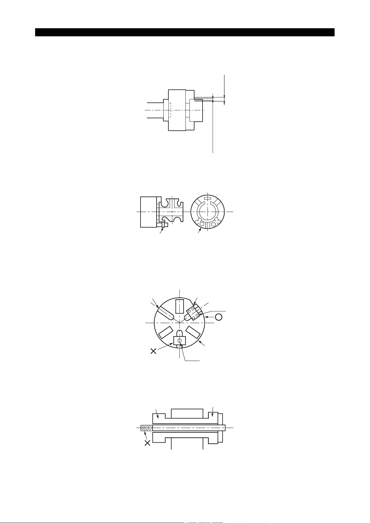
• Secure the jaw gripping depth as much as possible.
Must be
deep
LE11240R0100100160003
6097-E P-(xi)
SAFETY PRECAUTIONS
• When gripping a workpiece, soft top jaws must be at the central area of the entire jaws stroke
(see the illustration) or the base line mark on the master jaws must be located within the
appropriate chuck stroke range.
Entire stroke
Appropriate stroke range
Central one third of the entire stroke
LE11240R0100100160004
• Before machining an unbalanced workpiece, carry out balancing of the workpiece weight by
gradually changing the spindle speed.
Clamping block Balance weight
LE11240R0100100160005
• Never attempt to install jigs using T-nut.
Be sure to fix the jigs with bolts.
No chucks prepared by Okuma have T-groove.
T-slot
Jig
Bolt
Jaw
T-nut
LE11240R0100100160006
• When inserting a bar material into the hollow chuck, ensure that the bar does not protrude from
the rear end of the cylinder.
Cylinder
Hollow chuck
LE11240R0100100160007

• Never use double chucking method.
16. Caution Plate
• The machine and its components are fitted with various caution plates. Carefully read these
plates and follow the instructions described there.
• Do not tear or damage the caution plates. In case a plate has been lost or become illegible, ask
us for a new plate, quoting the Okuma part number written in this manual.
6097-E P-(xii)
SAFETY PRECAUTIONS
Chuck
Workpiece
LE11240R0100100160008
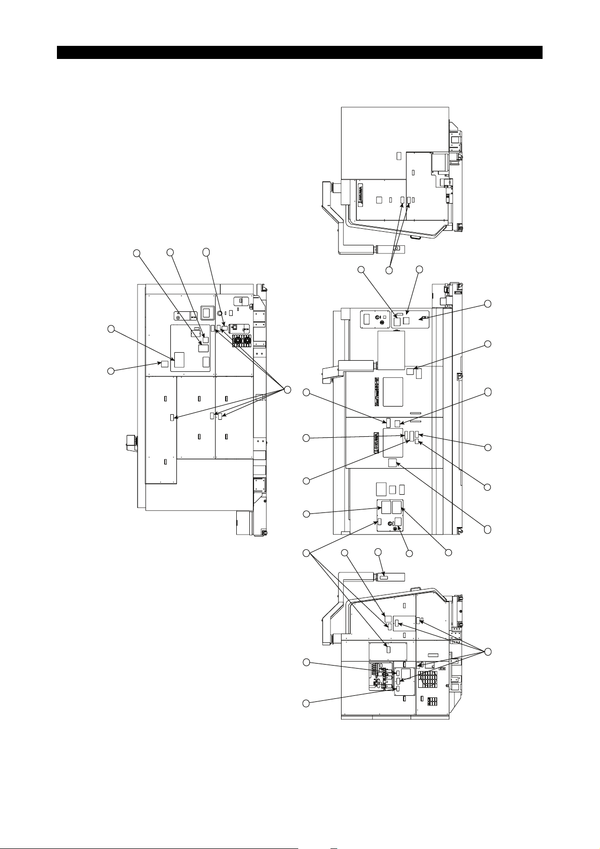
16-1. Caution Plate Positions
6097-E P-(xiii)
SAFETY PRECAUTIONS
14
16
9
13
23
4
10
10
21
19
5
1
18
17
9
22
8
7
20
10
12
11
6
15
3
2
10
LE11240R0100100180001

6097-E P-(xiv)
SAFETY PRECAUTIONS
Japanese English German Swedish Dutch
1 Warning caution H1090-1023-68-1 H1090-1164-54 H1090-1019-31-3 H1090-1029-74-3 H1044-1104-04-1
2 Instruction for oil supply to the machine body
(Model with sub spindle-OP)
3 Instruction for chuck pressure setting H1042-1173-79-3 H1044-1096-46-3 H1044-1099-06-3 H1044-1098-88-3 H1044-1103-96-2
4 Instruction for sub-chuck pressure setting (OP) H1042-1173-80-3 H1044-1096-47-4 H1044-1099-07-3 H1044-1098-89-4 H1044-1103-97-2
5 Warning H1090-1164-51-1 H1090-1164-52-1 H1090-1166-87-1 H1090-1166-88-1 H1090-1166-89-1
6 Warning against X-axis turret falling H1090-1046-45 H1090-1047-93 H1090-1048-23 H1090-1048-02 H1044-1104-08
7 Caution for cover removal H1090-1020-35 H1090-1018-33 H1090-1020-36-1 H1090-1020-37-2 H1090-1020-38-2
8 Caution for oil mist filter clogging H1090-1074-26 H1090-1074-27 H1090-1074-28-1 H1090-1074-29-1 H1090-1074-30
9 Caution for ABSOSCALE (OP) H1090-1074-33 H1090-1074-34 H1090-1074-35-1 H1090-1074-36-1 H1090-1074-37
10 Notice for ATC H1090-1019-87-1 H1090-1019-77-1 H1090-1019-82-2 H1090-1029-71-2 H1090-1074-42
11 Caution for magazine operation H1090-1039-34-3 H1090-1047-91-2 H1090-1048-21-3 H1090-1047-99-2 H1044-1104-06-2
12 Notice for touch setter (OP) H1090-1017-48-1 H1090-1024-07-1 H1090-1028-87-2 H1090-1029-96-1 H1090-1029-03-1
13 Notice for MG manual exchanging H1090-1054-39-1 H1090-1054-40-1 H1090-1054-63-2 H1090-1054-64-1 H1090-1074-43
14 Oil mist unit working pressure setting H1042-1156-74-2 H1044-1099-78 H1044-1099-82 H1044-1099-84 H1044-1104-02
15 Oil mist manifold pressure setting H1042-1156-73-2 H1044-1099-77 H1044-1099-81 H1044-1099-83-1 H1044-1104-01
16 Caution for safety glass H1090-1042-24 H1090-1041-56 H1090-1042-26-2 H1090-1042-30-2 H1090-1042-28-1
17 Caution for tool change H1090-1079-14 H1090-1079-48 H1090-1079-50-1 H1090-1080-05-1 H1090-1080-03
18 Door lock warning H1090-1050-06 H1090-1050-26 H1090-1057-69 H1090-1057-70 H1090-1057-71
19 Caution for footstep (OP) H1090-1090-62 H1090-1091-84 H1090-1091-85 H1090-1091-91 H1090-1091-94
H1090-1046-44-9 H1090-1187-47 H1090-1048-22-6 H1090-1048-01-7 H1090-1074-41-1
Danish French Italian Spanish Turkish
1 Warning caution H1090-1052-35-2 H1090-1019-23-2 H1090-1019-24-2 H1090-1032-96-2 H1090-1094-22-1
2 Instruction for oil supply to the machine body
(Model with sub spindle-OP)
3 Instruction for chuck pressure setting H1044-1101-33-3 H1044-1105-22-2 H1044-1101-79-2 H1044-1109-76-1 H1044-1115-33
4 Instruction for sub-chuck pressure setting (OP) H1044-1101-34-2 H1044-1106-22-2 H1044-1101-80-2 H1044-1109-80-1 H1044-1115-34
5 Warning H1090-1166-91-1 H1090-1166-92-1 H1090-1166-93-1 H1090-1166-94-1 H1090-1166-96-1
6 Warning against X-axis turret falling H1090-1052-79-1 H1090-1062-69 H1090-1053-72 H1090-1079-54-1 H1090-1095-91
7 Caution for cover removal H1090-1020-40-2 H1090-1018-34-1 H1090-1020-41 H1090-1024-12-1 H1090-1038-75-2
8 Caution for oil mist filter clogging H1090-1074-31-1 H1090-1062-65-1 H1090-1074-32 H1090-1079-59-1 H1090-1094-26
9 Caution for ABSOSCALE (OP) H1090-1074-38-1 H1090-1074-39 H1090-1074-40 H1090-1030-72-1 H1090-1078-95
10 Notice for ATC H1090-1019-86-2 H1090-1025-88-1 H1090-1029-83-1 H1090-1079-55 H1090-1094-27
11 Caution for magazine operation H1090-1052-34-4 H1090-1062-67-2 H1090-1053-36-2 H1090-1081-77-1 H1090-1094-28
12 Notice for touch setter (OP) H1090-1028-94-2 H1090-1028-88-1 H1090-1028-89-1 H1090-1029-63-2 H1090-1066-01-1
13 Notice for MG manual exchanging H1090-1054-65-2 H1090-1062-66-2 H1090-1054-66-1 H1090-1079-58 H1090-1095-94
14 Oil mist unit working pressure setting H1044-1101-16-1 H1044-1105-21 H1044-1101-48 H1090-1079-78-1 H1044-1115-35
15 Oil mist manifold pressure setting H1044-1101-15-1 H1044-1105-20 H1044-1101-47 H1090-1079-77-1 H1044-1115-36
16 Caution for safety glass H1090-1042-31-2 H1090-1042-27 H1090-1042-29-1 H1090-1042-25-1 H1090-1066-02-1
17 Caution for tool change H1090-1080-04-1 H1090-1079-51 H1090-1079-52 H1090-1081-79 H1090-1094-37
18 Door lock warning H1090-1057-73 H1090-1057-74 H1090-1057-75-1 H1090-1057-76 H1090-1057-41-1
19 Caution for footstep (OP) H1090-1091-90 H1090-1091-86 H1090-1091-87 H1090-1091-88 H1090-1091-93
H1090-1052-36-4 H1090-1065-76-3 H1090-1053-38-4 H1090-1079-57-1 H1090-1095-90
16-2. Caution Plates and Okuma Part Numbers
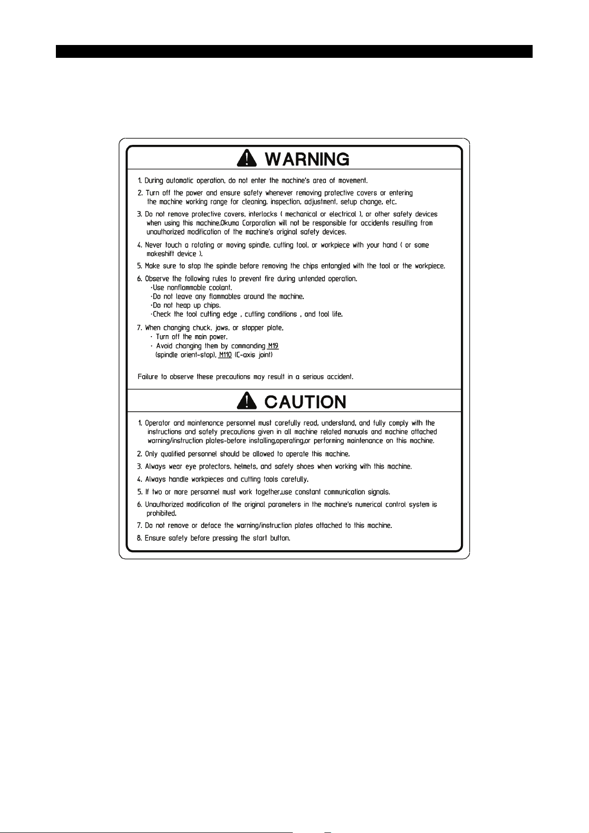
• [1] Warning caution
Okuma Part No. H1090-1164-54
6097-E P-(xv)
SAFETY PRECAUTIONS
LE11240R0100100190024

SAFETY PRECAUTIONS
• [2] Instruction for oil supply to the machine body (Model with sub spindle-OP)
Okuma Part No. H1090-1187-47
6097-E P-(xvi)
LE11240R0100100190025

• [3] Instruction for chuck pressure setting
Okuma Part No. H1044-1096-46-3
6097-E P-(xvii)
SAFETY PRECAUTIONS
• [4] Instruction for sub-chuck pressure setting (OP)
Okuma Part No. H1044-1096-47-4
LE11240R0100100190026
LE11240R0100100190027

• [5] Warning
Okuma Part No. H1090-1164-52-1
6097-E P-(xviii)
SAFETY PRECAUTIONS
• [6] Warning against X-axis turret falling
Okuma Part No. H1090-1047-93
Before removing X-axis feed servomotor for maintenance or
inspection of X-axis ball screw, servomotor or other related
parts, be sure to prevent the upper and lower turrets from
slipping down using wood blocks or the like.
Negligence of this may cause a turret to slip accidentally,
resulting in serious injury.
Example of Slip Preventive Measure
Optional
WARNING
Prop up the turrets
using wood blocks
LE11240R0100100190028
LE11240R0100100190029
• [7] Caution for cover removal
Okuma Part No. H1090-1018-33
CAUTION
ALWAYS TURN THE MAIN POWER SWITCH "OFF" BEFORE
REMOVING THIS COVER.
FAILURE TO FOLLOW THIS INSTRUCTION MAY RESULT IN
PERSONAL INJURY.
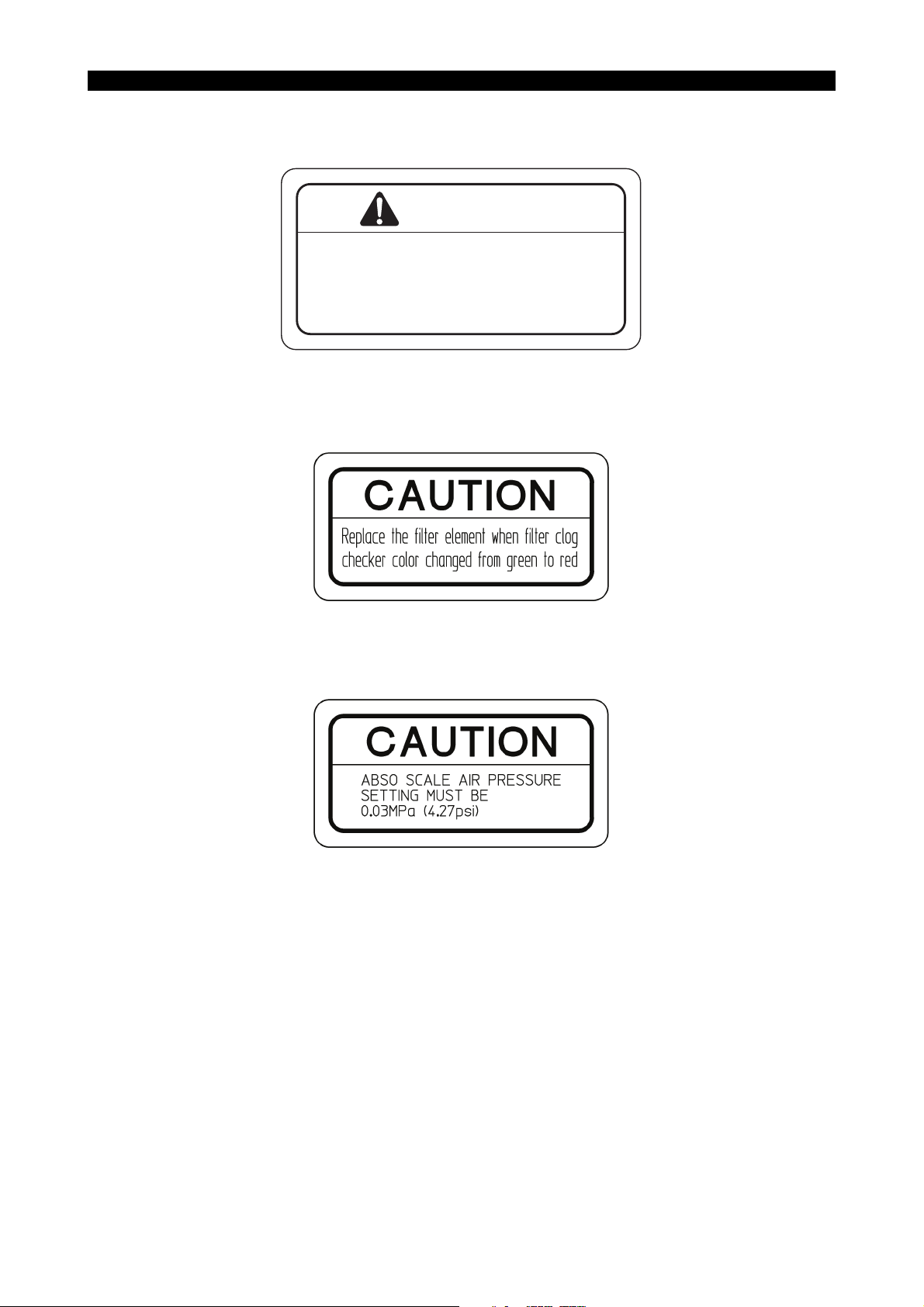
• [8] Caution for oil mist filter clogging
Okuma Part No. H1090-1074-27
6097-E P-(xix)
SAFETY PRECAUTIONS
LE11240R0100100190030
• [9] Caution for ABSOSCALE (OP)
Okuma Part No. H1090-1074-34
LE11240R0100100190031
LE11240R0100100190032
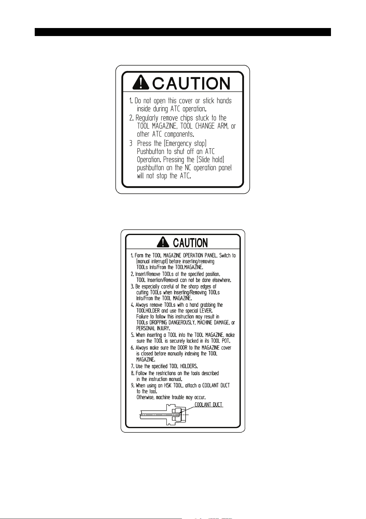
• [10] Notice for ATC
Okuma Part No. H1090-1019-77-1
6097-E P-(xx)
SAFETY PRECAUTIONS
LE11240R0100100190033
• [11] Caution for magazine operation
Okuma Part No. H1090-1047-91-2
LE11240R0100100190034
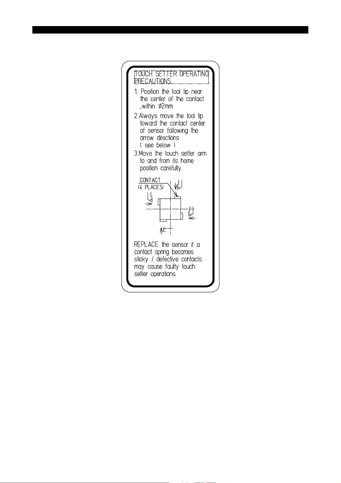
• [12] Notice for touch setter (OP)
Okuma Part No. H1090-1024-07-1
6097-E P-(xxi)
SAFETY PRECAUTIONS
LE11240R0100100190035
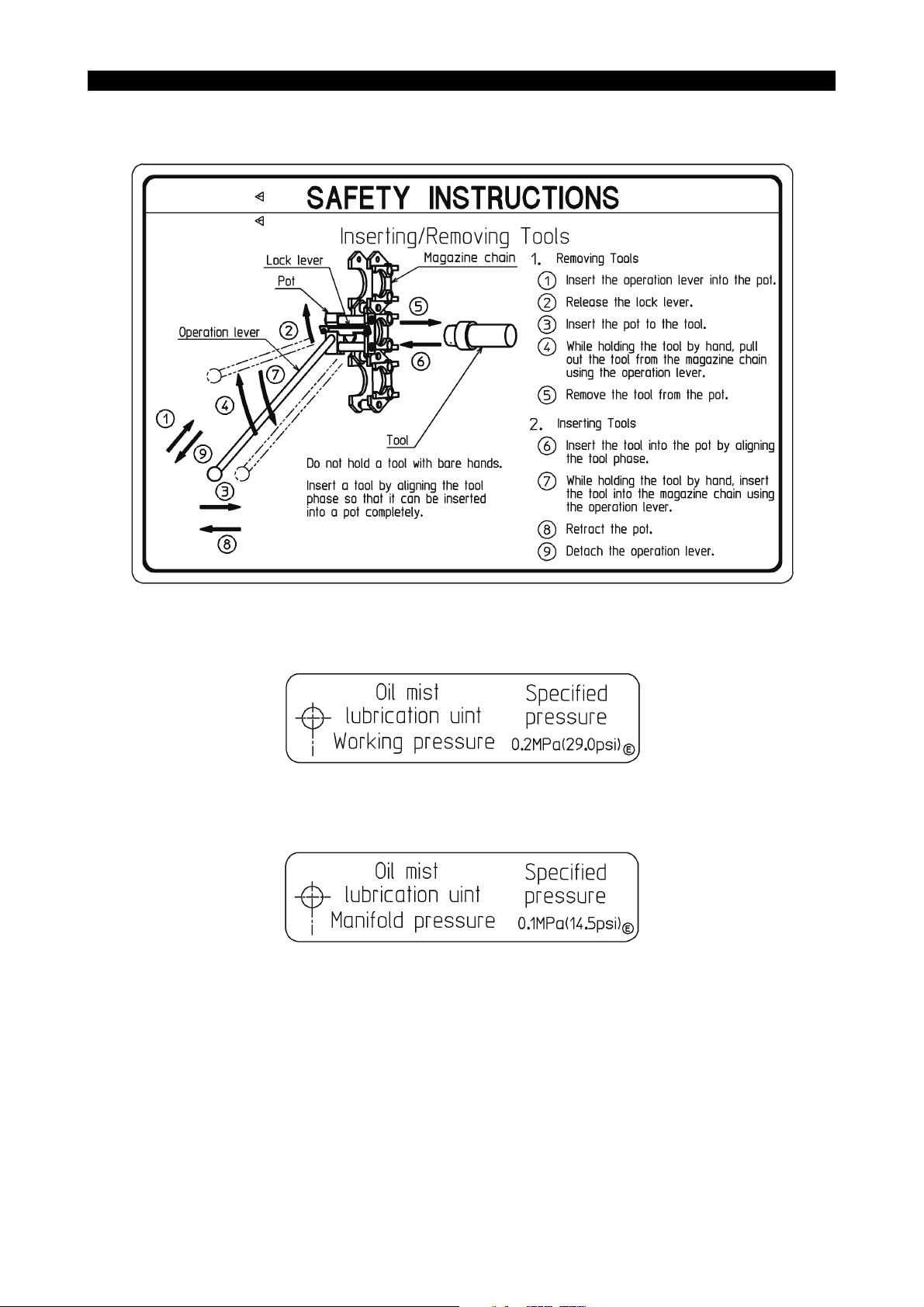
• [13] Notice for MG manual exchanging
Okuma Part No. H1090-1054-40-1
6097-E P-(xxii)
SAFETY PRECAUTIONS
• [14] Oil mist unit working pressure setting
Okuma Part No. H1044-1099-78
• [15] Oil mist manifold pressure setting
Okuma Part No. H1044-1099-77
LE11240R0100100190036
LE11240R0100100190037
LE11240R0100100190038

• [16] Caution for safety glass
Okuma Part No. H1090-1041-56
• [17] Caution for tool change
Okuma Part No. H1090-1079-48
6097-E P-(xxiii)
SAFETY PRECAUTIONS
LE11240R0100100190039
LE11240R0100100190040
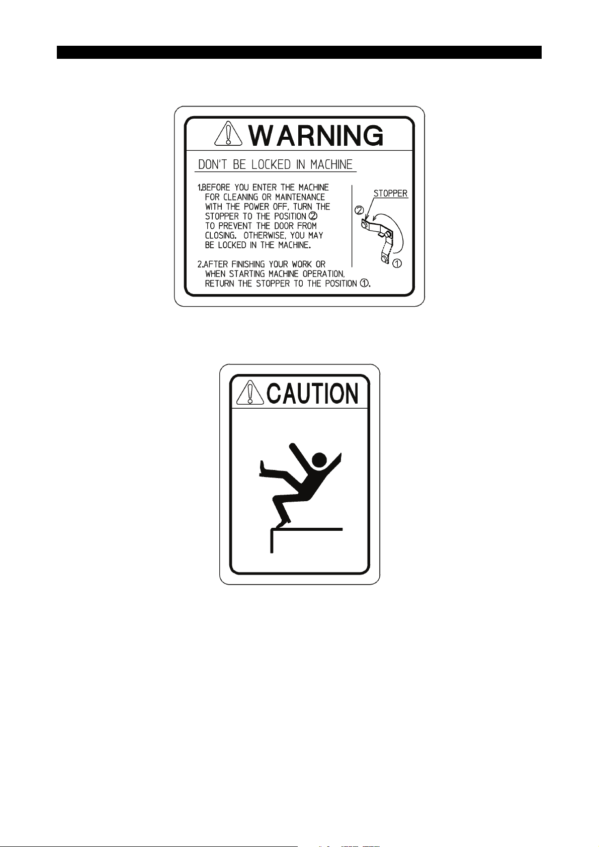
• [18] Door lock warning
Okuma Part No. H1090-1050-26
6097-E P-(xxiv)
SAFETY PRECAUTIONS
LE11240R0100100190041
• [19] Caution for footstep (OP)
Okuma Part No. H1090-1091-84
LE11240R0100100190023

6097-E P-(i)
INTRODUCTION
INTRODUCTION
This manual explains the proper handling of the machine to make the best use of its performance and the
maintenance inspection to maintain the machining accuracy for a long period of time. Carefully read this
manual and follow the instructions described there.

6097-E P-(i)
TABLE OF CONTENTS
TABLE OF CONTENTS
SECTION 1 OUTLINE...............................................................................................1
1-1. Machine Overview ............................................................................................................. 1
1-1-1. Features of Machine Components ...................................................................... 2
1-1-2. Features of Machine Functions ........................................................................... 2
1-1-3. Workpieces and Tools......................................................................................... 3
1-2. Machine Specifications ......................................................................................................4
1-2-1. Specification Table .............................................................................................. 4
1-2-2. Dimensional Drawing .......................................................................................... 7
SECTION 2 TRANSPORTATION AND INSTALLATION (RELOCATION).................8
2-1. Site Selection Guidelines...................................................................................................8
2-1-1. Water for Plant .................................................................................................... 8
2-1-2. Care in Machine Transportation .......................................................................... 8
2-2. Foundation Requirements ............................................................................................... 10
2-2-1. Safety Instructions for Foundation Work ........................................................... 10
2-3. General Procedure for Installation ................................................................................... 11
2-3-1. Installation Procedure........................................................................................ 11
2-3-2. Precautions for Installation ................................................................................ 11
2-4. Leveling the Machine....................................................................................................... 12
2-4-1. Leveling Procedure ........................................................................................... 12
2-5. Foundation Plan .............................................................................................................. 13
2-6. Power Requirements and Fuse Capacity ........................................................................ 14
2-6-1. Inspection of Cable Connection ........................................................................ 15
2-7. Oils to Be Prepared before Installation ............................................................................ 16
SECTION 3 OPERATION (OF CNC LATHE) ..........................................................17
3-1. Before Starting Operations .............................................................................................. 17
3-1-1. NC Operation .................................................................................................... 17
3-2. Machine Operation .......................................................................................................... 18
3-2-1. Axis Direction .................................................................................................... 18
3-2-2. Hydraulic Power Unit ......................................................................................... 19
3-2-3. Spindle Speed Selection (Transmission Power/Torque Diagram) .................... 23
3-2-4. Rotary Tool (M-tool) Spindle Power-Torque Diagram ....................................... 29
3-2-5. C-axis Brake...................................................................................................... 32
3-2-6. Hydraulic Power Chuck ..................................................................................... 33
3-2-7. Cutting Soft Top Jaws of Power Chuck............................................................. 45
3-2-8. Hydraulic Tailstock Operation ........................................................................... 46
3-2-9. Precautions in Handling Turret .......................................................................... 51
3-2-10. ATC ................................................................................................................... 52
3-2-11. Interlock............................................................................................................. 67

TABLE OF CONTENTS
3-2-12. After Completion of a Day’s Operation.............................................................. 68
3-2-13. Manually Operated Chuck ................................................................................. 69
SECTION 4 INSPECTION/MAINTENANCE (FOR TROUBLE-FREE
OPERATION) ......................................................................................75
4-1. Preparation of Air Source ................................................................................................ 76
4-1-1. Moisture............................................................................................................. 76
4-1-2. Filter Drain......................................................................................................... 76
4-1-3. Selecting a Compressor .................................................................................... 76
4-2. Lubrication ....................................................................................................................... 77
4-2-1. Lubricating Oil Specification .............................................................................. 79
4-2-2. Spindle Lubrication System ............................................................................... 80
4-2-3. Lubrication System for Bed/Saddle/Cross-slide Slideways ............................... 80
4-2-4. Turret ................................................................................................................. 81
4-2-5. ATC Cam Box ................................................................................................... 81
4-2-6. Maintenance and Inspection of HSK Tool Clamping Unit (HSK Tool
Specification) ..................................................................................................... 82
6097-E P-(ii)
4-3. Adjusting Centralized Lubrication Unit............................................................................. 84
4-3-1. Adjusting Pump Delivery ................................................................................... 84
4-3-2. Maintenance and Countermeasure ................................................................... 84
4-3-3. Other Remarks .................................................................................................. 85
4-4. Inspecting and Replenishing Oil Mist Lubrication Unit..................................................... 86
4-4-1. Air Flow Rate..................................................................................................... 86
4-4-2. Checking Air Pressure....................................................................................... 86
4-4-3. Replenishment .................................................................................................. 87
4-5. Lubrication and Cleaning of Spindle Cooling Unit ........................................................... 88
4-5-1. Main Spindle Cooling Unit ................................................................................. 88
4-5-2. Rotary Tool (M-tool) Spindle Cooling Unit......................................................... 90
4-5-3. Sub Spindle Cooling Unit .................................................................................. 92
4-6. Removing Sludge from Coolant Unit ............................................................................... 94
4-6-1. Procedure for Cleaning Separate Coolant Tank ............................................... 94
4-6-2. Cleaning the Filter ............................................................................................. 95
4-6-3. Cleaning the Fine Chips Collection Bucket ....................................................... 95
4-6-4. Thickener Bag Filter (Changing Procedure of Element).................................... 96
4-7. Collecting Used Lubricating Oil ....................................................................................... 97
4-8. Tensioning Belts .............................................................................................................. 98
4-8-1. Timing Belt for the XB-axis Servomotor ............................................................ 98
4-9. Adjusting the ATC............................................................................................................ 99
4-10. Other Maintenance Items .............................................................................................. 101
4-10-1. Alignment of Headstock .................................................................................. 101
4-10-2. Measures to Be Taken when Inspecting X-axis Ball Screw ............................ 102
4-11. Front Door Safety Window Glass Replacement ............................................................ 103
4-11-1. Replacement Interval ...................................................................................... 103
4-11-2. Replacement Procedure.................................................................................. 104

6097-E P-(iii)
TABLE OF CONTENTS
4-12. Troubleshooting ............................................................................................................. 111
4-12-1. Trouble with Headstock................................................................................... 111
4-12-2. Trouble with Turret .......................................................................................... 112
4-12-3. Others.............................................................................................................. 113
SECTION 5 SPARE PARTS LIST .........................................................................114
5-1. Air Unit........................................................................................................................... 114
5-2. Hydraulic Equipment ..................................................................................................... 115
5-3. Electrical Parts (Mounted in Machine)........................................................................... 116
5-4. Consumable Parts ......................................................................................................... 117
SECTION 6 TECHNICAL DATA ............................................................................121
6-1. Tooling System ..............................................................................................................121
6-1-1. BT-40 Tooling (BIG-PLUS Specifications) ...................................................... 121
6-1-2. HSK-A63 Tooling............................................................................................. 122
6-1-3. CAPTO-C6 Tooling ......................................................................................... 123
6-1-4. Tooling System (Lower Turret) ........................................................................ 124
6-2. Toolholder Dimensions .................................................................................................. 125
6-2-1. BT40 (BIG PLUS Specifications)..................................................................... 125
6-2-2. HSK Tool ......................................................................................................... 132
6-2-3. CAPTO-C6 Tool .............................................................................................. 141
6-2-4. Toolholder Dimensions (Lower Turret) ............................................................ 149
6-3. Lower Turret Tool Interference Diagram (Turret Rotation) ............................................ 154
6-4. Classification of Tools.................................................................................................... 155
6-4-1. BT40 (BIG PLUS Tooling) ............................................................................... 157
6-4-2. HSK-A63 ......................................................................................................... 160
6-4-3. CAPTO-C6 ...................................................................................................... 163
6-5. Working Ranges ............................................................................................................ 166
6-5-1. Turning Tool (BT40 BIG PLUS) [Tailstock Model]........................................... 166
6-5-2. Turning Tool (BT40 BIG PLUS) [Sub Spindle Model] ..................................... 170
6-5-3. Turning Tool (HSK-A63) [Tailstock Model]...................................................... 178
6-5-4. Turning Tool (HSK-A63) [Sub Spindle Model]................................................. 186
6-5-5. Turning Tool (CAPTO-C6) [Tailstock Model]................................................... 202
6-5-6. Turning Tool (CAPTO-C6) [Sub Spindle Model] ............................................. 210
6-5-7. Rotary Tool (BT40 BBT40-NBS20-90) ............................................................ 222
6-5-8. Rotary Tool (HSK-A63 tool A63DN-CTH20-90S06)........................................ 228
6-5-9. Turning Tool (Lower Turret) ............................................................................ 234
6-5-10. Working Ranges of Upper and Lower Turrets in Longitudinal Direction.............. 244
6-5-11. B-axis Rotation Range .................................................................................... 245
6-6. Dimensions of Spindle Nose ......................................................................................... 246
6-7. Hydraulic Power Chuck and Cylinder ............................................................................ 249
6-8. Hydraulic Circuit Diagram .............................................................................................. 252
6-9. Air Circuit Diagram ........................................................................................................ 254

6097-E P-(iv)
TABLE OF CONTENTS
6-10. Piping Drawings............................................................................................................. 255
6-10-1. Hydraulic Piping .............................................................................................. 255
6-10-2. Pneumatic Piping ............................................................................................ 265

SECTION 1 OUTLINE
1-1. Machine Overview
This machine is an NC-controlled, high-speed, high-precision multitasking machine. The machine
has a main spindle for turning, opposite spindle or tailstock for turning, milling spindle, lower turret,
and ATC unit. Besides turning, it can perform multitask machining such as milling, drilling, boring,
tapping and grinding using the indexing function (B-axis) for indexing the H1 turret at a desired angle
in a single setup. The lower turret greatly reduces machining time. The opposite spindle model can
transfer a workpiece between the main spindle and the opposing spindle, enabling front-back
machining of the workpiece.
The machine, designed for high-speed and high-precision machining, can also promote automation
and labor saving. With high productivity and machining accuracy, the machine is suitably used for
machining of parts in a wide application range including automobiles, construction equipment,
airplanes, hydraulic/pneumatic equipment, and molds.
The machine is available in six types; "2ST type" having no opposing spindle or tailstock, "2SC type"
having a tailstock, "2SW type" having an opposing spindle, "1ST type" having no opposing spindle,
tailstock or lower turret, "1SC type" having a tailstock but no lower turret, and "1SW type" having an
opposing spindle but no lower turret.
6097-E P-1
SECTION 1 OUTLINE
Axis Moving Directions in the Machine Coordinate System
B-axis (-)
H1 turret
M spindle
forward rotation
C-axis (+)
C-axis (-)
Main spindle
XB-axis (-)
B-axis (+)
M spindle
reverse rotation
W-axis (-)
ZA-axis (-)
C-axis (-)
C-axis (+)
Y-axis (+)
Opposing spindle or tailstock
XA-axis (+)
XA-axis (-)
W-axis (+)
ZA-axis (+)
Y-axis (-)
ZB-axis (-)
XB-axis (+)
Axis moving directions
ZB-axis (+)
Lower turret
LE11240R0100300010001

1-1-1. Features of Machine Components
(1) Main spindle
6097-E P-2
SECTION 1 OUTLINE
• Bearing diameter: Φ100 (3.94), driven by a built-in motor, max speed: 5,000 min
(Optional bearing diameter: Φ120 (4.72), and max speed: 3,800 min
• High power spindle: 22/15 kW (30/20 hp) (20 min/cont at 5,000 min
(Optional: 22/15 kW (30/20 hp), max 3,800 min
(2) Opposing spindle
• Bearing diameter: Φ80 (3.15), driven by a built-in motor, max speed: 6,000 min
(Optional bearing diameter: Φ100 (3.94), and max speed: 5,000 min-1)
• High power spindle: 11/7.5 kW (15/10 hp) (20 min/cont at 6,000 min
(Optional: 11/7.5 kW (15/10 hp), max 5,000 min
(3) Milling tool spindle (M spindle)
• Driven by a built-in motor, max speed 6,000 min
• High power spindle: 11/7.5/5.5 kW (15/10/7.5 hp)
-1
(3 min/20 min/cont at 6,000 min
, 12,000 min-1, 11/7.5/5.5 kW (15/10/7.5 hp))
1-1-2. Features of Machine Functions
-1
-1
-1
)
-1
-1
)
-1
(Optional: 12,000 min-1)
-1
)
)
-1
)
(1) High-speed positioning at a rapid traverse of 40 m/min (1,574.80 ipm) (ZA-, ZB-, W-axis), 30 m/
min (1,181.10 ipm) (XA-, XB-axis), and 26 m/min (1,023.62 ipm) (Y-axis)
(2) Extremely low thermal deformation realized by a unique construction and control of the
machine
(3) ATC storage capacity: up to 44 tools (with options)
(4) A wide variety of options are available such as coolant unit, chip handling equipment, automatic
gauging unit, tool management, and fixtures.
(5) A full-enclosure shielding is provided as standard equipment to keep the working environment
clean.

1-1-3. Workpieces and Tools
(1) Workpiece materials
The machine can cut ordinary structural steels represented by carbon steel, ferrous material
such as castings, and non-ferrous material such as aluminum.
The machine can also cut non-metallic materials such as ceramics or graphite. These
materials, however, require dust preventive measures to protect the human body and the
machine from dust. Consult us for the measures.
When cutting an ignitable material, provide sufficient safety measures according to 6.
Precautions against Fire under "Safety Precautions" at the beginning of this operation manual.
(2) Max Workpiece Size and Mass
For the maximum machining dimensions, refer to 1-2-1. "Specification Table" of the subsection
1-2 "Machine Specifications" under SECTION 1 of this operation manual. The machine can
handle up to the following workpiece mass (including the chuck weight):
One-side support (chuck work)= 110 kg (242 lb) [OP. 180 kg (396 lb)]
Support between centers (center work)= 350 kg (770 lb)
An imbalanced workpiece may disable the machine to exert its full performance even if the
workpiece size and mass are within the allowable ranges. Take the workpiece balance into
consideration and make sure that the workpiece is securely chucked to ensure safety in
machining.
6097-E P-3
SECTION 1 OUTLINE
(3) Maximum Tool Size and Mass
For the maximum tool size, see the requirements specified in 6-4-1, 6-4-2 and 6-4-3 of
SECTION 6 in this manual. The machine can handle a maximum tool mass of 7 kg (15 lb).
Even if the tool does not exceed the maximum mass, it cannot be used exceeding the
maximum tool mass moment specified in 3-2-10. of SECTION 3. If the tool is used at a rotation
speed exceeding the allowable limit, the tool breakage may result.

1-2. Machine Specifications
1-2-1. Specification Table
Item Unit MACTURN 350 MACTURN 350-W
CAPACITY
Swing over bed mm (in.) Φ530 (20.87)
Distance between noses mm (in.) 1940 (76.38)
Max. turning diameter mm (in.) Φ550 (21.65)
MAX. WORKPIECE
WEIGHT (including chuck
weight)
Main-spindle
Sub-spindle
MAIN SPINDLE
Spindle speed
Spindle diameter mm (in.) Φ100 (3.94) [OP. Φ120 (4.72)]
SUB SPINDLE
Spindle speed
Spindle diameter mm (in.) Φ80 (3.15) [OP. Φ100 (3.94)]
Z-AXIS
W-AXIS
X-AXIS
Y-AX I S
C-AXIS
Control angle degree 360 (Min. control angle 0.001)
B-AXIS
B-axis index range degree -15 to 195
One-side
support
Support
between
centers
One-side
support
Spindle nose JIS A2-6 (OP. JIS A2-8)
Spindle nose Φ140 (5.51) flat nose (OP. JIS A2-6)
Axis travel mm (in.) ZA: 1670 (65.75), ZB: 1655 (65.16)
Feedrate mm/min (ipm) 40,000 (1574.80)
Axis travel mm (in.) - 1680 (66.14)
Feedrate mm/min (ipm) - 40,000(1574.80)
Axis travel mm (in.) XA: 505 (19.88), XB: 210 (8.27)
Feedrate mm/min (ipm) 30,000 (1181.10)
Axis travel mm (in.) -95 (-3.74) to +95 (+3.74)
Feedrate mm/min (ipm) 26,000 (1023.62)
Feedrate
Index angle degree 1 (OP. 0.001)
kg (lb) 110 (242) [OP. 180 (396)]
kg (lb) 350 (770)
kg (lb) 50 (110) [OP. 110 (242)]
min
min
min
-1
-1
-1
38 to 5000 (OP. 38 to 3800)
50 to 6000 (OP. 50 to 5000)
6097-E P-4
SECTION 1 OUTLINE
200

SECTION 1 OUTLINE
Item Unit MACTURN 350 MACTURN 350-W
UPPER TURRET
Type H1
No. of tools 1 L or M tool
Tool
OD mm (in.) 25 sq. (0.98)
ID mm (in.) Φ40 (1.57)
Milling tool spindle speed
Milling tool spindle max.
min
-1
6000 (OP.12000)
N-m 65.1/47.7 (48.0/35.2) (5 min/20 min)
torque
TAI LSTO CK
Tailstock diameter mm (in.) Φ90 (3.54) -
Tailstock TAPERED BORE MT. No. 5 -
Tailstock travel mm (in.) 150 (5.91) -
LOWER TURRET (Option)
Type V12, VDI
No. of tools 12 L tools
Tool
OD mm (in.) 25 sq. (0.98)
ID mm (in.) Φ40 (1.57)
ATC M AGAZINE
Tool shank BT40 BIG PLUS or HSK-A63 or CAPTO-C6 or KM63
Max. tool mass kg (lb) 7 (15) [10 (22)]
Max. tool length mm (in.) 300 (11.81) (except shank part)
Max. tool diameter mm (in.) Φ130 (5.12)
Tool storage capacity No. of tools 30 (OP. 44)
MOTOR
Main spindle kW (hp) 22/15 (30/20) (20 min/cont.)
Sub spindle kW (hp) 11/7.5 (15/10) (30 min/cont.)
XB-axis kW (hp) 4 (5.3) × 1
XA-axis, ZA-axis, ZB-axis,
kW (hp) 6 (8.0) × 3 6 (8.0) × 4
W-axis
YS-axis kW (hp) 3 (4.0)
B-axis kW (hp) 2.8 (3.73)
Hydraulic pump kW (hp) 2.2 (3)
Lubrication pump kW (hp) 0.017 (0.0227)
Coolant pump kW (hp) 0.25 (0.333) × 2, 0.8 (1.07) x 2
Milling tool kW (hp) VAC 7.5/5.5 (10/7.5) (5 min/20 min)
Magazine rotary kW (hp) 0.75 (1)
ATC kW (hp) 3.6 (4.80)
POWER SOURCE
General power kVA 37.4 52.2
Voltage V 200
Primary voltage tap of
the transformer supplied
V 220/240/380/415/440/480
from Okuma
6097-E P-5

6097-E P-6
SECTION 1 OUTLINE
Item Unit MACTURN 350 MACTURN 350-W
Frequency Hz 50/60
Protect level for
control cabinet
MACHINE HEIGHT mm (in.) 2950 (116.14)
REQUIRED FLOOR
SPACE
NET MASS kg (lb) 13,700 (30,140) 13,700 (30,140)
mm × mm
(in. × in.)
IEC IP54
4560 × 2640
(179.53 × 103.94)

1-2-2. Dimensional Drawing
Side chip disposal type
1930 (75.98)722 (28.43)
3002 (118.19)
502
No. of magazine tools: 44
No. of magazine tools: 30
1966 (77.40)
436
(17.17)
(9.84)
250
(19.76)
796 (31.34)
2950 (116.14)
6097-E P-7
SECTION 1 OUTLINE
1147 (45.16)
Unit: mm (in.)
1200 (47.24)
Filter unit
Coolant pump
(for upper turret)
Coolant pump
(for lower turret, optional)
Coolant pump
(for chip flusher)
900 (35.43)
OSP control
2698 (106.22)
Magazine maintenance door
(37.24)
946
1857 (73.11)
1784.8 (70.268)
(2.56)
65
Opposing spindle cooling unit
Magazine operation panel
H1 upper turret cooling unit
cabinet
Hydraulic unit
Mesh filter
Coolant pump
(for suction)
1476 (58.11) 1100 (43.31)
Main spindle
cooling unit
Tailstock or
Opposing spindle
495
(19.49)
H1 upper turret
ATC
Lower turret
Main spindle
1630 (64.17)
Operation panel
Opposing spindle pressure
switch (optional)
Air panel
Centralized lubrication unit
H1 upper turret mist
lubrication unit
Main spindle pressure
switch (optional)
765(30.12)
Chip conveyor (optional) L type for side disposal
Chip bucket (optional)
700 (27.56)
185 (7.28)
1036 (40.79)
4555 (179.33)
450
(17.72)
Maintenance space
LE11240R0100300060001

6097-E P-8
SECTION 2 TRANSPORTATION AND INSTALLATION (RELOCATION)
SECTION 2 TRANSPORTATION AND INSTALLATION
(RELOCATION)
2-1. Site Selection Guidelines
Pay attention to the following points regarding machine installation in order to ensure machine
efficiency and performance.
(1) We recommend appropriate foundation work where the soil is soft or apt to sag after initial
installation. See [Foundation Requirements] for reference.
(2) The installation site should be kept as far as possible from vibration sources, such as roads,
stamping/press type equipment, or planer type machine tools. If nearby sources of vibration
are unavoidable, dampening pits around the machine foundation, for example, should help
lessen vibrations.
(3) Where there are high-frequency power generators, electric discharge machines or electric
welding machines around or when power is supplied from the same shop power distributor
panel, electrical interference may cause NC malfunctions. Please consult with the OKUMA
service engineer dispatched during machine installation.
(4) The ideal operating environment calls for an ambient temperature between 10 and 40°C (50
and 104°F) with humidity between 40 to 75% at 20°C (68°F).
(5) Keeping ambient temperature at a constant level is an essential factor for accurate machining.
(6) In order to maintain static machine accuracy within guaranteed values, the machine should be
installed in an area where it is not affected by airflow. Air conditioning is not essential, but an
ambient temperature between 17°C and 25°C (63 and 77°F) is recommended.
(7) To maintain static machine accuracy within the Standard Guaranteed Values:
a. Keep ambient temperature variance for a full day or 24 hours within ±2°C (36°F).
b. Ambient temperature variances from the floor level to a height of the machine (3 m (10 ft))
should be held within 1°C (34°F).
(8) Usually, no consideration is required on heat insulation against the machine foundation.
(9) Keep the floor level error within 10 mm (0.39 in.).
2-1-1. Water for Plant
Use potable water to dilute coolant.
Using water contains bacteria and salt may lead to malfunction of the machine parts.
2-1-2. Care in Machine Transportation
This machine integrates hydraulic unit, control cabinet, and NC unit into one construction instead of
having them as separate units, and so the machine can be easily moved or transported.
(Note that the coolant tank is installed separately.)
There are two different methods for moving the entire machine to any desired location; by an
overhead crane, using lifting hooks supplied together with the machine and by rolls over which the
machine is pushed by manual labor.

Lifting the Machine
6097-E P-9
SECTION 2 TRANSPORTATION AND INSTALLATION (RELOCATION)
Lifting frame
Pendant swing stopper
Upper saddle
Tailstock or
2nd headstock
Lifting hook
Lower saddle
(Optional)
Procedure :
Lifting hook
LE11240R0100400030001
1- Move the upper saddle to +600 (ZA-axis), the lower saddle to the negative limit (ZB-axis),
and the sub headstock to -700 (W-axis). Then, fasten them with the attached fixtures.
2- Remove the cables and pipes (coolant pump, lubricating oil collection tank and level switch)
between the machine and the coolant tank.
3- Pull out the coolant tank.
4- Locate the full-enclosure shielding cover doors in the positions shown in the above figure.
5- Remove the swing stopper from the pendant operation panel and fix the pendant with the
fixture as shown above.
6- Remove the cover at the upper part of the headstock and the upper part of the sub headstock
to pass the wire.
7- Mount the lifting hook at the 4 positions.
8- Mount the wire using the lifting tools.
Now, the machine is ready to be lifted.

6097-E P-10
SECTION 2 TRANSPORTATION AND INSTALLATION (RELOCATION)
Precautions for Lifting
• The cables should have a nominal diameter of 24 mm (0.94 in.) or larger.
• Change an angle formed by each cable line so that the cables will not contact the finished
surfaces of the machine.
(Do not tilt any wire rope exceeding 40 degrees away from the vertical direction.)
• Check for balance and be very careful when lifting the machine.
• Use extra care to lower the machine gently onto the floor; NEVER APPLY SHOCKS TO THE
MACHINE WHEN PLACING IT ON THE FLOOR.
Approximate Weight of Machine
Machine with 44-tool magazine: 13,700 kg (30,140 lb)
(Including the hydraulic power unit, the electrical control box, NC unit, and tool magazine)
Rolling
Be careful that the machine does not tip over on any side so that the machine base may not strike
the ground.
2-2. Foundation Requirements
2-2-1. Safety Instructions for Foundation Work
With a solid ground, a concrete floor about 200 mm (7.87 in.) thick and no gaps between ground
and floor, foundation work or anchoring is not required. The structural rigidity of the machine
permits normal machining.
For long-maintained accuracy and where sub-soil or ground under the floor is not strong enough,
a new concrete foundation should be set up in accordance with the “2-5. Foundation Plan” in this
section.
• Foundation requirements vary depending on the characteristics of the sub-soil. Under any soil
conditions, it is important that sub-soil should be well compacted to keep the foundation from
unsettling once the machine has been installed.
• Where sub-soil is too soft, it is necessary to drive concrete piles into the sub-soil.
• The Foundation Plan attached to this Manual is prepared for laying a typical concrete
foundation specifically for the machine. The concrete thickness or depth should be determined
in terms of the ground condition in each case.

SECTION 2 TRANSPORTATION AND INSTALLATION (RELOCATION)
2-3. General Procedure for Installation
2-3-1. Installation Procedure
Procedure :
1- Place leveling plates, 200 mm x 200 mm x 19 mm (7.87 x 7.87 x 0.75 in.) over individual
foundation bolt-holes.
Refer to the Foundation Plan.
2- Place foundation washers (furnished together with the machine) on the leveling plates and
then place the machine on them.
3- Pass foundation bolts through the hole in the leveling plate and a center bore through the
built-in jack screw assembly.
Secure each foundation bolt carefully, using a washer and a nut on its upper end.
4- Use wedge pieces, shims, or leveling blocks under the machine base to level the machine
approximately.
6097-E P-11
5- Pour mortar into the foundation bolt holes and allow it to set.
6- After the mixture has become hard enough, remove the shims or leveling blocks from under
the machine base, and level the machine within the specified limits.
2-3-2. Precautions for Installation
• Keep the underside of the leveling plates free from any oily substance.
• With leveling jack screws resting on foundation washers, the bottom surfaces of the machine
base casting should be about 10 - 20 mm (0.39 - 0.79 in.) above concrete floor level.
• Fill the foundation bolt holes with mortar so as to reach the underside of the respective leveling
plates. Be sure to compact the mortar thoroughly.
Leveling jack screw
Lock nut
Machine base
Nut and washer
Foundation bolt
Foundation washer
Leveling plate
The part names shown in are not supplied as standard equipment.
10 (0.39) to 20 (0.79)
Unit: mm (in.)
LE11240R0100400080001

SECTION 2 TRANSPORTATION AND INSTALLATION (RELOCATION)
2-4. Leveling the Machine
Levelness of the machine has great influence on machining accuracy and machine life. Therefore,
use particular care to level the machine when installing the machine.
6097-E P-12
Model No. of Leveling
Between centers: 1500 10 Pass foundation bolt.
2-4-1. Leveling Procedure
(1) When leveling the machine, index the spindlehead (B-axis) to 0° or 180°.
Mount the level stand to the turret. Put levels on the stand as shown in the figure below. Then,
check the levelness in X- and Y-axis directions at the right end and the left end of the bed
guideway.
Turret
Remarks
Jack Screws
Level
Level stand
LE11240R0100400100001
(2) Ensure that the leveling jack screws and the foundation bolts are firmly tightening before
checking the levelness.
Tolerance: 0.04 mm (0.0016 in.) per 1,000 mm (39.37 in.)
Leveling accuracy: 1 division (0.02 mm (0.0008 in.) per 1,000 mm (39.37 in.))

SECTION 2 TRANSPORTATION AND INSTALLATION (RELOCATION)
2-5. Foundation Plan
6097-E P-13
Levelling plate
Foundation
washer
Nut and washer
Foundation bolt
Lock nut
Jaw screw
40 (1.57)
300 (11.81)
(11.81)
300
Mortar injection port
485 (19.09)
Stop collar
380 (14.96)
700 (27.56)
1000 (39.37)
1000 (39.37)
1145 (45.08)
60 (2.36)
200
(7.87)
380
(14.96)
120
(4.72)
2445 (96.26)
128 (5.04)
Details of Installation
Detail of Foundation Bolt Assembly
815 (32.09)
1. This foundation plan is typical.
Note:
Spindle center
10 pc
10 pc each
10 pc
10 pc
M16
M16
Concrete thickness is determined in accordance with sub-soil conditions.
2. Customers should have on hand the parts for installation of machine
Unit: mm (in.)
60 (2.36)
1. Foundation bolt
20 (0.79)
These parts are available as options.
2. Nut and washer for above.
3. Levelling plate (150 x 150 x 19)
4. Stop collar
(7.87)
200
600 (23.62)
Control
497 (19.57)
983 (38.70)
860 (33.86)
860 (33.86)
Bed
840
(33.07)
480 (18.90)
Outline of full-enclosure shield
cabinet
(19.69)
500
480 (18.90)
250 (9.84)
(9.25)
235
20 (0.79)
895 (35.24)
10 (0.39)
1150 (45.28)
1758 (69.21)687 (27.05) 172 (6.77)
Standard spindle
nose end
815 (32.09)
710 (27.95) 1930 (75.98)
527 (20.75)
913 (35.94)
Operation panel
900 (35.43)
4560 (179.53)
900 (35.43)
750 (29.53)
Concrete range
530 (20.87)
100 (3.94)
4520 (177.95)
(6.30)
160
Concrete
Rubble
500 (19.69)
(78.74)
2000
φ150
(5.91)
100 (3.94)
LE11240R0100400110001
Concrete pile
(used for soft ground)

SECTION 2 TRANSPORTATION AND INSTALLATION (RELOCATION)
2-6. Power Requirements and Fuse Capacity
Power source: 3-phase, 200V±10%, 50/60Hz
6097-E P-14
Main motor AC
22/15kW (30/20 hp) (main spindle)
7.5/5.5 kW (10/7.5 hp) (sub spindle)
5.5/3.7 kW (7.5/5 hp) (M-tool spindle)
200 A or more
(for the machine with lower
turret)
Automatic circuit
breaker
Refer to Table 1
for breaker capacity.
Cable size
Ground
Refer to Table 1.
RST
E
Table 1 Capacity and Cable Size of Automatic Breaker for Branch Circuit
MT350 Breaker capacity
Main spindle
Sub spindle
1S-C
1S-W
2S-C
2S-W
Capacity
Cable size
Capacity
Cable size
Capacity
Cable size
Capacity
Cable size
11/7.5 kW
(15/10 hp)
80 mm
Rated current (A)
22/15 kW (30/20 hp)
15/11 kW
(20/15 hp)
150 A or over
50 mm
175 A or over
60 mm
150 A or over
50 mm
200 A or over
2
or over
22/15 kW
(30/20 hp)
2
or over
2
or over
2
or over
225 A or over
100 mm2 or over
Electrical
control box
Main switch
LE11240R0100400120001

SECTION 2 TRANSPORTATION AND INSTALLATION (RELOCATION)
2-6-1. Inspection of Cable Connection
The operator can check correctness of cable connection by reading the pressure gauge whether it
indicates the specified pressure level.
Confirm that the pressure gauge indicates the set pressure 4.4 MPa (638.4 psi).
When it indicates the specified pressure level, the electrical connection is correct.
1) Connect the ground wire to the external protective earth terminal (PE) in the control box.
2) Do not connect the power cord and the grounding wire in serial; if attempted, it will give
adverse affect to other equipment or cause malfunctioning of the leak breaker, etc.
3) When a leak breaker is used, select the one meeting the following rating.
• For inverter circuit use
• Sensitive current of 100 mA or more
• Middle-sensitivity high-speed inverter type
4) Check that the momentary voltage variation rate is 15% or less as shown in the diagram
below.
If the momentary voltage variation rate exceeds 15%, the acceleration/deceleration time of the
spindle may be lengthened or the protection circuit of the servo power unit may be activated.
5) For further information on instantaneous power regulation and power source inductance,
please inquire at your Okuma representative.
6) To furnish the power supply line in the machine, pull the cable under the control cabinet, which
is advantageous for the dust and water prevention. Apply the protection against dust and
water to the cable. The protection measurement is required also when pulled over the
cabinet.
In addition, hold the power supply cable appropriately so that the tension wire will not hang on
to the connection part of the main breaker of the power supply line.
6097-E P-15
R
3-phase power source
AC voltmeter
Spindle drive
S
motor control
T
unit
V
0
V
: Voltage applied to the motor at a standstill
V1: Maximum voltage in motor deceleration
Instantaneous voltage regulation=
Spindle drive
motor
V1-V
0
V
0
LE11240R0100400130001
× 100
Procedure :
1- Connect the AC voltmeter to the spindle drive motor control unit or the machine power
terminal as shown in the above figure.
2- Measure the voltage (V
3- Measure the maximum voltage (V
) applied to the spindle drive motor at a standstill.
0
) during deceleration of the spindle drive motor.
1

SECTION 2 TRANSPORTATION AND INSTALLATION (RELOCATION)
4- Calculate the instantaneous voltage regulation by the following formula:
Instantaneous voltage regulation = (V
Note
• The digital AC voltmeter makes a slow response, and therefore the measured value tends to be
a little lower than the actual value. It is recommended to use the analogue AC voltmeter.
• Shorter deceleration time makes the measurement difficult. Measure the voltage while
decelerating the motor from the possible highest speed.
• Obtain the instantaneous voltage regulation after ensuring that the alarm “Voltage regulation too
large” is not activated. This is because the alarm causes the motor control unit to restrict the
motor output.
- V0) / V
1
0 × 100
2-7. Oils to Be Prepared before Installation
Prepare the oils specified in “4-2. Lubrication” and “4-2-1. Lubrication Oil Specification” in Section
“Inspection/Maintenance”.
(For oils to be supplied to an optional kit, check with us separately.)
6097-E P-16

6097-E P-17
SECTION 3 OPERATION (OF CNC LATHE)
SECTION 3 OPERATION (OF CNC LATHE)
This manual mainly explains the manual operation so that the operator can get used to the machine operation
as soon as possible.
3-1. Before Starting Operations
This section deals mainly with the operating procedures of your CNC lathe under manual control.
So the information given here is essential to every operator, whether you are new to a CNC lathe or
an “old pro”.
Follow these three points:
• Actually operate the CNC lathe by yourself in reference to this Instruction Manual.
• Learn the symbols for the numerical control terms.
• After you have a general idea of how your CNC lathe operates, read this manual repeatedly and
also the Programming Manual.
Bring the machine to a complete stop by turning off the main switch before operations such as
setup or adjustments inside the chip guard are carried out.
Also turn off the main switch before you attempt to work inside the machine at the rear side of the
machine.
3-1-1. NC Operation
Before you begin to operate the machine automatically by tape, make it a rule to check the following
points against a process sheet, a program manuscript, or any other chart giving detailed machining
instructions:
(1) Setting of hydraulic power chuck jaws and their gripping pressure
(2) Installation and arrangement of individual cutting tools with respect to their operating sequence
(3) Setting of tool offsets
(4) Setting of zero offsets
(5) Setting of feedrate override to 100%
(6) Setting of software limit positions for each axis
(7) Positioning of the turret to the turret indexing position
(8) Positioning of tailstock (when the machine is equipped with tailstock)
All essential information on the setup and check-up procedures is described in the sections that
follow.

3-2. Machine Operation
3-2-1. Axis Direction
6097-E P-18
SECTION 3 OPERATION (OF CNC LATHE)
B-axis (-)
H1 turret
forward rotation
Main spindle
XB-axis (-)
M spindle
C-axis (-)
C-axis (+)
B-axis (+)
M spindle
reverse rotation
W-axis (-)
C-axis (-)
C-axis (+)
Y-axis (+)
XA-axis (+)
ZA-axis (-)
XA-axis (-)
Opposing spindle or tailstock
W-axis (+)
ZA-axis (+)
Y-axis (-)
ZB-axis (-)
XB-axis (+)
ZB-axis (+)
Lower turret
LE11240R0100500100001

3-2-2. Hydraulic Power Unit
6097-E P-19
SECTION 3 OPERATION (OF CNC LATHE)
Pressure switchPressure gauge
System pressure
adjusting valve
Variable delivery pump
Suction filter
Radiator
Oil filler port
Oil level gauge
Level switch
Drain port
Line filter
LE11240R0100500110001
Pressure Indication
The pressure gauge should indicate the following set pressure:
Pressure setting 4.4 MPa (638.4 psi)

Adjustment of Pressure
The following outlines the methods of setting individual functional units for operating pressure.
Since the pressure lines for the turret(s) have been adjusted at our factory before shipment, they
will not require readjustments, during the initial installation and subsequent normal service of the
machine.
When readjustment is to be made by your plant personnel, extreme caution must be taken in
accordance with the instructions given here to avert any mechanical trouble in the drive lines.
• System pressure adjustment (Adjustment is not usually required.)
Pressure decrease Pressure increase
System Pressure Adjusting Valve
• Hydraulic pressure for main spindle chuck
Refer to “Adjustment of Oil Pressure for Hydraulic Chuck” in “3-2-6. Hydraulic Power
Chuck”described later.
6097-E P-20
SECTION 3 OPERATION (OF CNC LATHE)
Source pressure abnormal alarm setting pressure: 2 MPa (290 psi)
LE11240R0100500130001
• Tailstock pressure adjustment
Adjust the pressure using the tailstock thrust adjusting valve.
Tailstock thrust pressure gauge
Tailstock thrust adjusting valve
Main spindle hydraulic chuck pressure gauge
Main spindle hydraulic chuck pressure adjusting valve
LE11240R0100500130002

SECTION 3 OPERATION (OF CNC LATHE)
• Hydraulic pressure for sub spindle chuck
Adjust with the sub spindle hydraulic chuck pressure adjusting valve.
Pressure gauge for the hydraulic chuck of the opposing spindle
Pressure adjusting valve for the hydraulic chuck of the opposing spindle
6097-E P-21
Main spindle hydraulic chuck pressure gauge
Main spindle hydraulic chuck pressure adjusting valve
LE11240R0100500130003
Hydraulic Oil
Oil Specification HM32 (ISO)
Amount 20 liter (5.3 gal)
Oil Change Interval Change after first month of operation and every 6 months thereafter.
Clean the suction filter, the line filter, and the tank when changing the oil. Check the pressure for
respective actuators.
A clogged filter element causes contaminated oil to circulate through the hydraulic system, which
may lead to a machine trouble.

6097-E P-22
SECTION 3 OPERATION (OF CNC LATHE)
When changing the element, proceed as follows:
Filter Element Specifications
Procedure :
1- Turn off the power (be sure to turn off the main switch).
2- Unscrew and remove the filter housing by turning the nut portion of the housing provided at
the bottom.
3- Pull out the filter element downward.
4- Clean the inside of the housing.
5- Insert a new element into the body.
6- Screw and fit the housing onto the body.
Body
Housing
Filter element
(Housing removing margin needed to
change the element: 157 (6.18))
24
(0.94)
[27.7 (1.091)]
Nut portion of the housing
Unit: mm (in.)
Maker Yamashin
Type PX040A with a filtering accuracy of 10 μm (400 μin.)
Part No. H0032-0009-96
LE11240R0100500140001

6097-E P-23
(
(
)
SECTION 3 OPERATION (OF CNC LATHE)
3-2-3. Spindle Speed Selection (Transmission Power/Torque Diagram)
Main Spindle Power-Torque Diagram - 5,000 min-1 (Φ100 (3.94 in.) spindle)
VAC 22/15 kW (30/20 hp) (20 min/cont.) specification
1000
500
300
200
100
Spindle Torque [N-m (lbf-ft)]
420.2 N
286.5 N
168.1 N⋅m (124.1 lbf-ft)
114.6 N⋅m (84.6 lbf-ft)
50
30
20
10
5
3
2
⋅m (310.1 lbf-ft)
⋅m (211.5 lbf-ft)
22 kW (30 hp)
(20 min)
15 kW (20 hp)
(cont.)
100
50
30
20
10
5
3
2
1
]
hp
kW
Spindle Motor Output [
1
38
30 50 100
Spindle Speed min
2000 5000200 300 500 1000
-1
LE11240R0100500150001

6097-E P-24
SECTION 3 OPERATION (OF CNC LATHE)
For heavy-duty cutting, select a spindle speed in the shaded area so that cutting is performed within
a constant output range.
• Low-speed/high-speed range is changed by switching the VAC motor coil connection (switching
takes approx. 1 sec.)
5000
1250
M42
1250
500
3838
M41
LE11240R0100500150002
In conjunction with the above graph, refer to the Hydraulic Chuck Clamping Force characteristics
Diagram (the graph that shows the relation between the chuck rotation speed and its gripping
force).

6097-E P-25
SECTION 3 OPERATION (OF CNC LATHE)
Main Big-Bore Spindle (OP.) Power-Torque Diagram 3,800 min-1, Φ120 (4.72
in.), VAC 22/15 kW (30/20 hp) (20 min/cont.)
1000
500
300
200
100
Spindle Torque [N-m (lbf-ft)]
420.2 N-m (310.1 lbf-ft)
286.5 N-m (211.5 lbf-ft)
168.1 N-m (124.1 lbf-ft)
114.6 N-m (84.6 lbf-ft)
50
30
20
10
5
3
2
22 kw (30 hp)
(20 min)
15 kw (20 hp)
(cont.)
100
50
30
20
10
5
3
2
1
Spindle Motor Output [kW (hp)]
1
38
30 50 100
Spindle Speed min
2000 3800200 300 500 1000
-1
LE11240R0100500160001

6097-E P-26
SECTION 3 OPERATION (OF CNC LATHE)
For heavy-duty cutting, select a spindle speed in the shaded area so that cutting is performed within
a constant output range.
• Low-speed/high-speed range is changed by switching the VAC motor coil connection (switching
takes approx. 1 sec.)
3800
1250
M42
1250
500
3838
M41
LE11240R0100500160002
In conjunction with the above graph, refer to the Hydraulic Chuck Clamping Force characteristics
Diagram (the graph that shows the relation between the chuck rotation speed and its gripping
force).

6097-E P-27
(
(
)
SECTION 3 OPERATION (OF CNC LATHE)
Sub Spindle Speed-Power-Torque Diagram 6,000 min-1 (Φ80 (3.15 in.) spindle)
VAC 11/7.5 kW (15/10 hp) (20 min/cont.) specification
1000
500
300
200
100
50
30
20
Spindle Torque [N-m (lbf-ft)]
10
5
3
2
161.6 N-m (119.3 lbf-ft)
110.2 N-m (81.3 lbf-ft)
100.0 N-m (73.8 lbf-ft)
68.2 N-m (50.3 lbf-ft)
11 kW (15 hp)
(20 min)
7.5 kW (10 hp)
(cont.)
100
50
30
]
20
hp
10
kW
5
3
2
Spindle Motor Output [
1
1
5030
38
100
Spindle Speed min
1000500300200 60002000
-1
LE11240R0100500170001

6097-E P-28
SECTION 3 OPERATION (OF CNC LATHE)
For heavy-duty cutting, select a spindle speed in the shaded area so that cutting is performed within
a constant output range.
• Low-speed/high-speed range is changed by switching the VAC motor coil connection (switching
takes approx. 1 sec.)
6000
1050
1050
450
5050
LE11240R0100500170002
In conjunction with the above graph, refer to the Hydraulic Chuck Clamping Force characteristics
Diagram (the graph that shows the relation between the chuck rotation speed and its gripping
force).

SECTION 3 OPERATION (OF CNC LATHE)
65.7 N-m (48.5 lbf-ft) (3 min)
44.7 N-m (33.0 lbf-ft) (20 min)
32.8 N-m (24.2 lbf-ft) (cont.)
7.5 kW (10 hp) (20 min)
5.5 kW (7.5 hp) (cont.)
3-2-4. Rotary Tool (M-tool) Spindle Power-Torque Diagram
Rotary Tool Spindle Power-Torque Diagram 6,000 min-1, VAC 11/7.5/5.5 kW
(15/10/7.5 hp) (3 min/20 min/cont.)
6097-E P-29
kW (hp)
10
5
Spindle Power
1
0.5
0.1
65.7 N-m (48.5 lbf-ft) (3 min)
65.7 N-m (48.5 lbf-ft) (3 min)
44.7 N-m (33.0 lbf-ft) (20 min)
44.7 N-m (33.0 lbf-ft) (20 min)
32.8 N-m (24.2 lbf-ft) (cont.)
32.8 N-m (24.2 lbf-ft) (cont.)
50 100 1000 6000500
Spindle Speed
11 kW (15 hp) (3 min)
7.5 kW (10 hp) (20 min)
7.5 kW (10 hp) (20 min)
5.5 kW (7.5 hp) (cont.)
5.5 kW (7.5 hp) (cont.)
3300
1600
N-m (lbf-ft)
100
50
10
5
-1
min
Spindle Torque
LE11240R0100500180001
When performing powerful machining using M-tool spindle, select a spindle speed from the constant
output range (shaded range). The M-tool spindle has only one speed range (no switching between
high and low speed ranges).
50
60001600
LE11240R0100500180002

6097-E P-30
7.5 kW (10 hp) (20 min)
5.5 kW (7.5 hp) (cont.)
61.8 N-m (48.5 lbf-ft)
42.1 N-m (31.1 lbf-ft)
30.9 N-m (22.8 lbf-ft)
26.3 N-m (19.4 lbf-ft)
17.9 N-m (13.2 lbf-ft)
13.1 N-m (9.7 lbf-ft)
SECTION 3 OPERATION (OF CNC LATHE)
Rotary Tool Spindle Power-Torque Diagram 12,000 min-1, VAC 11/7.5/5.5 kW
(15/10/7.5 hp) (3 min/20 min/cont.)
kW (hp)
10
5
Spindle Power
1
0.5
0.1
11 kW (15 hp) (3 min)
7.5 kW (10 hp) (20 min)
7.5 kW (10 hp) (20 min)
5.5 kW (7.5 hp) (cont.)
5.5 kW (7.5 hp) (cont.)
61.8 N-m (45.6 lbf-ft)
61.8 N-m (48.5 lbf-ft)
42.1 N-m (31.1 lbf-ft)
42.1 N-m (31.1 lbf-ft)
30.9 N-m (22.8 lbf-ft)
30.9 N-m (22.8 lbf-ft)
17.9 N-m (13.2 lbf-ft)
17.9 N-m (13.2 lbf-ft)
13.1 N-m (9.7 lbf-ft)
13.1 N-m (9.7 lbf-ft)
50
100 1000 10000
26.3 N-m (19.4 lbf-ft)
26.3 N-m (19.4 lbf-ft)
4000
1700
Spindle Speed
12000
N-m (lbf-ft)
100
50
10
5
-1
min
Spindle Torque
When performing powerful machining using M-tool spindle, select a spindle speed from the constant
output range (shaded range). The M-tool spindle has only one speed range (no switching between
high and low speed ranges).
50
50
LE11240R0100500190001
1700 4000
120004000
LE11240R0100500190002

6097-E P-31
p
SECTION 3 OPERATION (OF CNC LATHE)
Lower turret M Specification (Optional) 7.0/3.3 kW (9.33/4.40 hp) (30 min/
cont.)
N·m (lbf-ft)
Spindle Torque
kW (hp)
7.0 kw (9.33 hp) (30 min)
3.3 kw (4.40 hp) (cont.)
23.7 N-m (17.5 lbf-ft)
14 N-m (10 lbf-ft)
indle Power
S
Spindle Speed
LE11240R0100500680001

3-2-5. C-axis Brake
[Supplement]
For the C-axis, three kinds of brakes are applied meeting the machine operation.
• C-axis indexing (rapid feed)
Brake free
• Cutting while controlling C-axis (profile generation etc.)
Brake pressure low setting: 0.5 MPa (72.6 psi)
• Cutting while clamping C-axis (keyway cutting, etc.)
Brake pressure 4.4 MPa (638.4 psi)
Arrangement of C-axis control related hydraulics:
Solenoid valve for
brake pressure switching
6097-E P-32
SECTION 3 OPERATION (OF CNC LATHE)
Pressure
gauge for brake pressure
Pressure adjusting
valve for low-pressure brake
Setting pressure for low-pressure brake should be 0.5 MPa (72.6 psi)
LE11240R0100500200001

3-2-6. Hydraulic Power Chuck
The construction of hydraulic chuck is shown below.
6097-E P-33
SECTION 3 OPERATION (OF CNC LATHE)
Connecting
rod
Installation of Hydraulic Chuck
Master jaw
Chuck body
Nut
Draw screw A
Draw tube
Solid Chuck
Top jaw
Wedge plunger
Mounting bolt B
Jaw nut
Pilot bushing
Draw tube
Mounting
bolt B
Jaw nut
Hollow Chuck
Top jaw
CHUCK
operating pedal
LE11240R0100500210001
Procedure :
1- Press the CONTROL ON pushbutton switch on the operation panel and step on the CHUCK
operation foot panel. This causes the connecting rod (draw tube) in the spindle bore to move
forward.
2- Fasten the connecting rod to the draw screw A. (Fasten the draw tube to the chuck.)
* Use the Allen wrench furnished with the machine.
3- Secure the chuck body onto the spindle end, using mounting bolts B.
4- Adjust the draw screw A so that the outer ends of the master jaws become flush with the
peripheral surface of the chuck body when the top jaws are in the OPEN condition.
The individual chuck jaws can be moved in the “opening” direction as the draw screw A is turned in
the counterclockwise direction. Removal of the hydraulic chuck from the spindle is the reverse of
installation in steps from “3-” to “2-”.
When changing parts such as chuck, jaws, or stopper block inside the chip and coolant shield,
keep the following in mind:
• Always shut off the source power before changing parts.
• Never issue M19 (spindle orientation) or M110 (C-axis joint) command while changing parts.

Hollow chuck cylinder
Hydraulic cylinder
6097-E P-34
SECTION 3 OPERATION (OF CNC LATHE)
Hydraulic chuck
Draw tube
Proximity switches
Dog
LE11240R0100500230001
Position of the dog moving with the hydraulic rotary cylinder piston is detected by the proximity
switches to confirm the chuck jaw position. (optional)

6097-E P-35
SECTION 3 OPERATION (OF CNC LATHE)
Adjustment of Oil Pressure for Hydraulic Chuck
The gripping pressure of the chuck jaws is dependent upon the working pressure of hydraulic fluid
which is determined by the setting of the chuck pressure adjusting valve installed at the front of the
machine. (See “3-2-2. Hydraulic Power Unit” described previously.)
A clockwise turn of the valve knob increases the working oil pressure directed into the chuck
cylinder and counterclockwise turn decreases it.
The allowable maximum pressure is indicated in the table below. Adjust the pressure meeting the
types of chuck.
Maximum Permissible Spindle Speeds and Oil Pressure Setting
Maximum permissible spindle speed varies depending on types of chuck and cylinder to be used.
See the table below:
No. Types and Size MPa (psi)
Hollow type
Main
Sub 1
1
B-208A601C
Solid type
2
N-08A601A
Hollow type
B206-01
2.9 (420.8) 4800 SS1452C01
2.1 (304.7) 4500 Y1225R(E)
2.6 (377.3) 6000 SS1243C01
min
-1
Type of Cylinder
This table indicates the permissible spindle speed for standard chuck. If a chuck other than those
indicated above is used, follow the instruction on the name plate at the front cover of the
machine.
How to Set Maximum Spindle Speed
The maximum spindle speed to which spindle speed is to be limited due to chuck specifications,
influence of centrifugal force on chuck gripping force, imbalance of workpiece, etc. can be set by
program.
Format:
G50 S OOOO ⋅⋅⋅⋅⋅⋅⋅⋅⋅⋅⋅⋅To be specified in a block without other commands
Specify the required maximum spindle speed.
LE11240R0100500260001
Programmed maximum spindle speed is effective until another spindle speed is designated.

6097-E P-36
SECTION 3 OPERATION (OF CNC LATHE)
Notes for Setting Proximity Switch (Optional)
Method of adjusting proximity switch position in longitudinal direction
For hollow cylinder
Loosen the screws clamping the two proximity switch plates to slide them with the proximity switch
to determine the position. After determining the position, tighten the proximity switch plate clamp
screws.
Proximity switch
plate clamping screw
(2 screws each)
Slide
Proximity switch
Adjusting
stroke
Dog
Proximity switch
LE11240R0100500280001

SECTION 3 OPERATION (OF CNC LATHE)
Setting Proximity Switches
OD chucking
Set the proximity switches at the positions as indicated below:
Proximity switch (A):
Piston advance end
Proximity switch (B):
Chuck gripping position
(B) (A)
6097-E P-37
Chuck gripping position
Piston retract end
(jaw close end)
(A) (B)
Chuck Side
Piston advance end
(jaw open end)
LE11240R0100500290001
LE11240R0100500290002
Always actually clamp the workpiece to set the proximity switch at the chuck gripping position.

SECTION 3 OPERATION (OF CNC LATHE)
ID chucking
Set the proximity switches at the positions as indicated below:
Proximity switch (B):
Piston retract end
Proximity switch (A):
Chuck gripping position
(B) (A)
6097-E P-38
Piston advance end
(jaw close end)
Chuck gripping position
Piston retract end
(jaw open end)
LE11240R0100500300001
(A) (B)
LE11240R0100500300002
Always actually clamp the workpiece to set the proximity switch at the chuck gripping position.

6097-E P-39
SECTION 3 OPERATION (OF CNC LATHE)
Confirmation Signals
Signal input status display
Whether the proximity switches are correctly set or not and the corresponding signals are on or off
can be checked on the check [IO monitor] screen.
For the procedure to display the [IO monitor] screen, refer to the [OSP-P300S MAINTENANCE
MANUAL].
(1)
LE11240R0100500310001
1 The input location of proximity limit is shown. When proximity switches have been input, they are highlighted in the
display.
Checking input signals
When the proximity switches are set in position, their signal status changes as indicated below
according to the chuck status.
• OD chucking:
At chuck gripping position
iCHOPC.......0
iCHCLC.......1
At piston advance end position
iCHOPC.......1
iCHCLC.......0
• ID chucking:
At chuck gripping position
iCHOPC.......1
iCHCLC.......0
At piston retract end position
iCHOPC.......0
iCHCLC.......1

6097-E P-40
SECTION 3 OPERATION (OF CNC LATHE)
Chuck clamp/unclamp confirmation timer
There may be cases in which the chuck open/close is not completed even if the corresponding
signal is input. For such cases, timer function can be used to delay the confirmation of the chuck
operation after the input of the signal.
The timers should be previously set at the following parameters.
• Machine user parameter (chuck)
Chuck clamp confirmation timer
This timer operates on receiving the signal from the proximity switch at the chuck gripping
position until the chuck clamping is completed.
• Machine user parameter (chuck)
Chuck unclamp confirmation timer
This timer operates on receiving the signal from the proximity switch at the piston advance end
(for OD gripping) or the proximity switch at the piston retract end (for ID gripping) until the chuck
unclamping is completed.
Set both timers in units of 0.01 sec. The default chuck clamp confirmation time is 100 (1sec) and the
default chuck unclamp confirmation time is 0.
For the procedure of setting machine user parameters, refer to the OSP Operation Manual.

6097-E P-41
SECTION 3 OPERATION (OF CNC LATHE)
Hydraulic Chuck Clamping Force Characteristics Diagram - Main spindle -
Chuck speed - clamping force diagram for solid chucks
25243 N
(5680 lbf)
(372.91 psi)
: Y1225R(E)
: N-10A0601A
: 2.57 MPa
Chuck
Cylinder
Pressure
)
-1
28495 N
(6411 lbf)
(4010 min
(322.13 psi)
: Y1225R(E)
: N-08A0601A
: 2.22 MPa
Chuck
Cylinder
Pressure
3000 4000 4500
-1
Soft top-jaw A
Chuck Rotating Speed min
10000 2000
105000
100495
90000
75000
69930
60000
45000
30000
Clamping Force N (lbf)
LE11240R0100500340001

SECTION 3 OPERATION (OF CNC LATHE)
Chuck speed - clamping force diagram for hollow chucks
: B-210A601C
: 3.6 MPa (522.4 psi)
: SS1452C01
Chuck
Cylinder
Pressure
: B-208A601C
: 2.9 MPa (420.8 psi)
: SS1452C01
28914N
(6506 lbf)
29283N
(6589 lbf)
6097-E P-42
Chuck
Cylinder
Pressure
3000 4000 4500
-1
Soft top-jaw A
Chuck Rotating Speed min
10000 2000
105000
103283
90000
75000
78133
60000
45000
30000
Clamping Force N (lbf)
LE11240R0100500350001

6097-E P-43
SECTION 3 OPERATION (OF CNC LATHE)
Hydraulic Chuck Clamping Force Characteristics Diagram - Sub spindle -
Chuck speed - clamping force diagram for hollow chucks [Sub spindle]
60000
57000
50000
40000
30000
20000
Clamping Force jaw 3 PC [N (lbf)]
19000
13000
10000
29 (1.14)
Chuck : B-206-01
Cyinder : SS1243C01
Pressure : 2.6MPA (377.3 psi)
26 (1.02)
B-206 Standard soft jaw
66 (2.60)
10000 2000 3000 4000 5000 60005600
Chuck Rotating Speed
(min-1)
LE11240R0100500360001

6097-E P-44
SECTION 3 OPERATION (OF CNC LATHE)
General Precaution for Using Power Chucks
In order to insure maximum safety in operation, the following points call for your special notice:
• Select the right chuck that matches the machine’s capacity.
• Spindle speed and chuck clamping force
Workpieces should be clamped in the chuck without imbalance. Cutting conditions must be
selected by referring to the “Hydraulic Chuck Clamping Force Characteristics Diagram” in “32-6. Hydraulic Power Chuck” since chuck jaw gripping force varies depending on the spindle
speed.
The maximum spindle speed and maximum allowable pressure limit (maximum setting) are
indicated on the instruction plate attached to the right and left front doors.
The maximum spindle speed refers to the speed at which the chuck can be turned, with its
gripping force maintained more than one-third of its rating, while the outer ends of the
individual top jaws are positioned evenly with the peripheral surface of the body.
• When soft top jaws larger than standard ones provided with the machine are prepared by the
customer and used with the chuck, keep in mind that developing centrifugal force and
decreasing efficiency may reduce the actual gripping force. Be sure to reduce the spindle
speed accordingly.
• Where jaw nuts shown below go beyond the peripheral surface of the body, only one bolt
secures the corresponding jaw and a very dangerous condition is created. Always locate the
jaw nuts within the periphery of the body as shown below. It is a good and safe practice to use
soft top jaws that are made to fit the actual work configuration.
Jaw nut Jaw
Wrong Right
LE11240R0100500370001
• Before starting spindle rotation, be sure to close the front door.
Change of Chuck Gripping Direction - ID/OD Gripping
Gripping direction of the power chuck - ID gripping and OD gripping - can be changed by pressing
the flat key on the operation panel.
The change of gripping direction may be made only while the spindle stops.
Greasing
The chuck has grease nipples either on the chuck front face or on its periphery. Apply grease
(mamufacturer's recommended grease) to the nipples every day.
Since chips and foreign matter accumulate on the jaw moving surfaces on the chuck, clean them
every day and lubricate them with the hydraulic oil (HM32, MAS).

SECTION 3 OPERATION (OF CNC LATHE)
3-2-7. Cutting Soft Top Jaws of Power Chuck
There are three different methods applied in cutting soft top jaws of chuck jaws for chucking a
particular lot of parts.
• by pulse feed handwheel
• by NC data
• by manual data input (MDI)
They are all basically the same operations, and it is advisable to use the NC data or the manual data
input when a good finish on the chucking surfaces of the jaws is essential.
Now let’s explain the steps necessary to produce the top jaws for chucking the diameter of 70 mm
(2.76 in.) with a depth of 15 mm (0.59 in.) by use of the manual data input.
(0.59)
B
A
6097-E P-45
15
φ70 (2.76)
φ50 (1.97)
Ring
Unit: mm (in.)
LE11240R0100500400001
Procedure :
1- Grip a ring of proper diameter in the chuck:
Φ50 mm (1.97 in.) ring for instance
2- Locate the tool tip point at point A and set the zero offset value so that the actual position of
X-axis is equivalent to the ring diameter; 50 mm (1.97 in.) in this case.
Actual Position: X = 50 mm (X = 1.97 in.)
3- Locate the tool tip point at point B and set the zero offset value so that the actual position of
Z-axis is equivalent to the required chucking depth of length; 15 mm (0.59 in.) in this case.
Actual Position: Z = 15 mm (Z = 0.59 in.)

4- Proceed with cutting by entering the following commands block by block.
In the example, the depth of cut is 5 mm (0.20 in.) and the feedrate is 0.1 mm/rev (0.004 ipr).
The spindle speed must be selected to suit the operation.
G50 S
G00 X60 Z 18 S M41 M03
G01 Z 0.1 F0.1
G00 X58 Z 18
X69.6
G01 Z 0.1
G00 X67 Z 18
X70
G01 Z 0
X48
G00 Z500 M05
3-2-8. Hydraulic Tailstock Operation
Tailstock Position Setting (When moved manually)
Procedure :
6097-E P-46
SECTION 3 OPERATION (OF CNC LATHE)
LE11240R0100500400002
1- Move the turret to the X-axis plus limit position.
Column
Tailstock joint block
Tailstock joint pin
LE11240R0100500410001
2- Move the saddle to align the center of the tailstock joint block and the center of the tailstock
joint pin.
3- After connecting the tailstock to the column, unclamp the tailstock.
4- Move the saddle using the pulse handle to bring the tailstock to a required position.

6097-E P-47
SECTION 3 OPERATION (OF CNC LATHE)
5- Extract the joint pin from the saddle.
When extracting the joint pin after moving the saddle and tailstock using the pulse handle,
feed the saddle about 0.5 mm (0.020 in.) in reverse direction using the handle. This is to
prevent a side of the joint pin from contacting the joint block when the pin is extracted.
(In MDI or automatic operation mode, the above reverse feed is automatically performed.)
Adjusting Tailstock Spindle Thrust
Tailstock spindle thrust can be adjusted by the pressure adjusting valve at the right side of the
machine front. For details, refer to SECTION 3, 3-2-2 Adjustment of Pressure. Maximum tailstock
thrust is 2.1 MPa (304.7 psi) and the thrust with such pressure setting is 4,900 N (1,103 lbf).
Note that the tailstock spindle thrust largely affects the service life of the main spindle; do not set
the thrust unnecessarily high.
Relation between hydraulic oil pressure and tailstock spindle thrust:
N
4900 (1103)
3920 (882)
2940 (662)
1960 (441)
980 (221)
Tailstock Spindle Thrust N (lbf)
0
0.4
(58.0)
Hydraulic Oil Pressure MPa (psi)
0.8
(116.1)
1.2
(174.1)
1.7
(246.7)
2.1
(304.7)
MPa
LE11240R0100500420001
Center-work/Chuck-work Selector Switch
Set whether the tailstock is to be used (center-work) or not to be used (chuck-work) by setting
parameters.
Center-work : The tailstock sleeve operates by the foot pedal switch.
The main spindle can rotate only when the left foot pedal switch is stamped to the
second step.
Chuck-work : The tailstock does not operate.
The main spindle can rotate only when the tailstock sleeve is at the retract end.

SECTION 3 OPERATION (OF CNC LATHE)
Advancing or Retracting the Tailstock Sleeve
Advance or retract the tailstock sleeve using the foot pedal switches in the front.
6097-E P-48
Left foot pedal switch (2-step type)
for sleeve advance
Right foot pedal switch (1-step type)
for sleeve retract
LE11240R0100500440001
(a) Left foot pedal switch (2-step type) - For advancing the tailstock sleeve
First step (the pedal is lightly stamped)
(The spindle does not rotate.)
Second step (the pedal is fully stamped)
(The spindle rotates.)
- The sleeve advances while the pedal remains
stamped.
- The sleeve advances to the to the sleeve
stroke end by stamping the foot pedal switch.
(b) Right foot pedal switch (1-step type) - For retracting the tailstock sleeve
The sleeve retracts to the sleeve stroke end
by stamping the foot pedal switch.
Allowable Loads and Speeds of the Rotating Center
Use the rotating center under the allowable loads of standard rotating center MT No. 5 shown in the
table below:
[min-1]
4200
4000
3000
2000
Spindle Speed
1000
3
9
2
0
4
9
0
0
N
(
1
1
0
N
3
l
b
2
3
(
8
8
2
f
)
Thrust load
9
4
0
N
(
6
4
3
0
N
(
7
l
b
f
)
6
2
l
b
f
)
7
2
l
b
f
)
0
0 2000 4000 6000 8000 10000 [Hr]
Lifetime
LE11240R0100500450001

SECTION 3 OPERATION (OF CNC LATHE)
Tailstock Spindle Advance/Retraction Position Confirmation Device
(Optional)
Procedure :
1- Move the dog rightward.
Adjusting screw
6097-E P-49
Overadvance confirmation proximity switch
In-position confirmation proximity switch
Dog
Retract end
confirmation proximity switch
LE11240R0100500460001
2- Turn the adjusting screw clockwise using an Allen wrench.
3- The dog then moves rightward.
4- Advance the tailstock spindle (50 mm (1.97 in.) or over) as desired and reposition the
tailstock body so that the workpiece is hold by the tailstock spindle. Step the tailstock spindle
advance pedal to the 2nd position. Under such setup, turn the adjusting screw until both the
in-position detection proximity switch and the overadvance detection proximity switch
become activated.
Adjusting screw
Overadvance confirmation proximity switch
In-position confirmation proximity switch
Dog
LE11240R0100500460002
5- Turn the adjusting screw counterclockwise with the workpiece pressed by the tailstock
spindle.
6- The dog moves leftward. First locate the dog at the position where both of the overadvance
and the in-position signals are output from the corresponding proximity switches. Further
turn the adjusting screw two turns from that point.
7- The signal output status can be checked on the CRT display as detailed in (4) below.

SECTION 3 OPERATION (OF CNC LATHE)
8- In case workpiece length varies, adjust the dog position by turning the knob:
counterclockwise for longer workpiece and clockwise for shorter workpiece.
9- Checking correct position
Correct position:Both of the overadvance and in-position proximity switches have been
actuated.
1) After selecting any of AUTO, MDI and MANUAL modes, press the
function key [F7] (CHECK DATA).
2) Press the PAGE key several times, and the I/O CHECK screen is
displayed.
3) Refer to the table on the next page.
Bit 4 of INPUT is the tailstock spindle in-position confirmation
(tailstock work pos) input signal and bit 3 the tailstock spindle over
advance (tailstock over advance) input signal. The signal is ON when
the label is highlighted.
1 indicates ON and 0 indicates OFF.
4) When both bit 4 and bit 3 are highlighted, it indicates that both of the
in-position and the overadvance confirmation proximity switches are
actuated and the tailstock spindle is located in position.
6097-E P-50

3-2-9. Precautions in Handling Turret
The turret incorporates a rotary tool drive unit.
To protect this drive unit, observe the following instructions.
H1 spindle that accepts either
turning tool or rotary tool
6097-E P-51
SECTION 3 OPERATION (OF CNC LATHE)
Spindlehead
LE11240R0100500470001
• Never wash the end face of H1 spindle by applying air blow or coolant brow.
• Before rotating the spindlehead, move the spindlehead to the area where it does not interfere
with the work or the chuck.
• The spindlehead may not be completely clamped immediately after it is rotated.
Therefore, wait at least 0.5 second before starting cutting operation.

3-2-10.ATC
Tool to be prepared: BT40, BIG-PLUS Specifications
• The tool shank is a NT No. 40 taper for milling machine.
• The tool gripper shall conform to BBT40. Especially, the distance between the trapezoidal
groove and the taper gauge line (Φ44.45 mm (1.7500 in.) part) shall be 16.6±0.1 (0.654±0.004).
(Refer to “Tool Shank Dimensions”.)
• Use the retention knob that conforms to JIS (6339-1992).
When the retention knob is firmly screwed into the tool rear end, the distance between the part
of the retention knob Φ19 (0.75 in.) and the taper gauge line (Φ44.45 mm (1.7500 in.) part)
must be retained.
(Refer to “Tool Shank and Retention Knob”.)
• The maximum tool length, measured from the taper gauge line (Φ44.45 mm (1.7500 in.) part) to
the tool nose, is 300 mm (11.81 in.).
• The maximum tool size stored in the magazine with its adjacent toolpots occupied conforms to
the standard tool size. Refer to the relevant drawings in SECTION 6.
6097-E P-52
SECTION 3 OPERATION (OF CNC LATHE)
• The maximum tool size stored in the magazine with its adjacent toolpots empty conforms to the
extra large-diameter tool size. Refer to the relevant drawings in SECTION 6.
• The maximum standard tool mass including the tool shank is 7 kg (15 lb). Heavy tool setting
allows the tool mass up to 10 kg (22 lb).
• The max tool mass moment is 500 kg-mm. The maximum tool mass is 7 kg (15 lb) and its
center of gravity shall be within 70 mm (2.76 in.) from the gauge line (Φ44.45 mm (1.7500 in.)
part).
• The toolpot can accept a face mill (full-back cutter) of up to Φ130 mm (5.12 in.) in diameter.
7 kg x 70 mm (15 lb x 2.76 in.)
7 kg (15 lb)
70 (2.76)
max. 300 (11.81)
Unit: mm (in.)
LE11240R0100500480001

6097-E P-53
SECTION 3 OPERATION (OF CNC LATHE)
Tool to be prepared: HSK-A63
Face brought into contact
with the spindle nose
LE11240R0100500490001
• The “tool shank” is HSK-A63. The shank and gripper dimensions shall conform to DIN 69893-1.
For turning tool, some dimensions are specially controlled to improve tool mounting accuracy.
Therefore please consult us when using a tool other than our standard tool.
• The “max tool length” from the face that fits the spindle nose to the tool tip is 300 mm (11.81 in.).
• The “max tool length with adjacent tools” or the dimension of the tool that can be used in
adjacent to the magazine tool gripper is the same with that of the standard tool. Refer to the
related drawings in SECTION 6.
• The “max tool length without adjacent tools” or the dimension of the tool that can be used with
the tool grippers adjacent to the magazine tool gripper kept empty is the same with that of the
super large diameter tool. Refer to the related drawings in SECTION 6.
• The “max tool mass” or the standard tool mass including the tool shank is 7 kg (15 lb). Heavy
tool setting allows the tool mass up to 10 kg (22 lb).
• The “max tool mass moment” is 500 kg-mm. The maximum tool mass is 7 kg (15 lb) but its
center of gravity shall be located within 70 mm (2.76 in.) from the face which brought into
contact with the spindle nose.

6097-E P-54
SECTION 3 OPERATION (OF CNC LATHE)
• The “face mill (full-back)” having a diameter of up to 130 mm (5.12 in.) can be installed.
7 kg x 70 mm
7 kg (15 lb.)
70 (2.76)
MAX 300 (11.81)
(15 lb. x 2.76 in.)
Section A-A
Unit: mm (in.)
LE11240R0100500490002
Coolant duct
LE11240R0100500490003
Use the holder with coolant duct shown in the figure above. Using the part other than the holder
with coolant duct may result in machine malfunction.

6097-E P-55
SECTION 3 OPERATION (OF CNC LATHE)
Tool to be prepared: CAPTO-C6 tool
Face brought into contact with
the spindle nose
Unit: mm (in.)
LE11240R0100500500001
• The “tool shank” conforms to CAPTO-C6. The shank and gripper dimensions shall conform to
CAPTO-C6 standard specified by Sandvic.
• The “max tool length” from the face that fits the spindle nose to the tool tip is 300 mm (11.81 in.).
• The “max tool length with adjacent tools” or the dimension of the tool that can be used in
adjacent to the magazine tool gripper is the same with that of the standard tool. Refer to the
related drawings in SECTION 6.
• The “max tool length without adjacent tools” or the dimension of the tool that can be used with
the tool grippers adjacent to the magazine tool gripper kept empty is the same with that of the
super large diameter tool. Refer to the related drawings in SECTION 6.
• The “max tool mass” or the standard tool mass including the tool shank is 7 kg (15 lb). Heavy
tool setting allows the tool mass up to 10 kg (22 lb).
• The “max tool mass moment” is 500 kg-mm. The maximum tool mass is 7 kg (15 lb) but its
center of gravity shall be located within 70 mm (2.76 in.) from the face which brought into
contact with the spindle nose.

6097-E P-56
SECTION 3 OPERATION (OF CNC LATHE)
• The “face mill (full-back)” having a diameter of up to 130 mm (5.12 in.) can be installed.
7 kg x 70 mm
7 kg (15 lb.)
70 (2.76)
MAX 300 (11.81)
(15 lb. x 2.76 in.)
Unit: mm (in.)
LE11240R0100500500002

Tool Shank and Retention Knob (JIS)
6097-E P-57
SECTION 3 OPERATION (OF CNC LATHE)
φ63 (2.48)
2 (0.08)
25 (0.98)
Gauge line
NT40 (taper 7/24)
φ44.45 (1.7500)
88.4
65.4 ± 0.15 (2.575 ± 0.0059)
67.4 (2.654)
25 (0.98)
+0.15
(3.480 )
-0.25
M16 P3
+0.0059
-0.0098
φ17 (0.67) H8/h7
0
23
(0.91 )
-0.1
29 (1.14)
54 (2.13)
15°
φ14 (0.55)
0
-0.004
φ23 (0.91)
φ19 (0.75)
92.4 (3.638)
Unit: mm (in.)
LE11240R0100500510001
[Supplement]
1) Tool shank shape and dimensions comply with MAS Standard BT 40 (403-1982).
2) The retention knob shape and dimensions comply to MAS Standard P40T2 (403-1982).

SECTION 3 OPERATION (OF CNC LATHE)
Tool shank dimensions (BT40, BIG-PLUS Specifications)
Excerpted from Bottle Grip Taper Shank (MAS 403-1982) and Daishowa Seiki Standard
0
30 -15030 -15
d
Gauge line
A
0.02 A
0.02 A
t
6097-E P-58
t
Nominal
No.
BT30
BT35
BT40
BBT40
BT45
BT50
BT55
BT60
Nominal
No.
BT30
BT35
BT40
BBT40
BT45
BT50
BT55
BT60
d2
D6D5D4
5
D1
v
7/24
x
1x
y 1
e
y
2
3
1
d1
60
R
4
w
0.05 A
Shank
14
14
19
19
23
27
33
33
d
H8
12.5
12.5
17
17
21
25
31
31
D
1
1 d1 W
0.2
31.75
38.10
44.45
44.45
57.15
69.85
88.90
107.95
101.8
126.8
161.8
48.4
56.4
65.4
65.4
82.8
R
(Max.)
0.5
0.5
1
1
1
1
1
1
Flange
20
22
25
26
30
35
40
45
v
0.1
13.6
14.6
16.6
16.6
21.2
23.2
26.2
28.2
4
5
5
5
6
7
9
11
D
D
38
43
53
53
73
85
107
135
5
4 D6ex d
h8
46
53
63
63
85
100
125
155
Thread Slot on Flange
2
M12
M12
M16
M16
M20
M24
M30
M30
2
(Min.)
24
24
30
30
38
45
56
56
(Min.)
3
34
34
43
43
53
62
76
76
4
0.5
0
11.0
13.0
16.0
16.0
7.0
7.0
9.0
9.0
b
H126H
16.1
16.1
16.1
16.1
19.3
25.7
25.7
25.7
Allowance
x1
0.1
0
8
10
10
10
12
15
18
20
y
0.4
y1
0
0.4
2
2
2
2
2
2
1
1
3
3
3
3
3
3
3
3
of
7/24 Taper
AT
D
0.0039
0
0.0045
0
0.0041
0
0.0041
0
0.0052
0
0.0051
0
0.0063
0
0.0065
0
Smaller
Diameter
end
17.633
21.650
25.375
25.375
33.000
40.158
51.917
60.758
5
(Min.)
17
20
21
21
26
31
31
34
Reference
t
0
0.2
16.3
19.6
22.6
22.6
29.1
35.4
45.1
60.1
8
10
10
10
12
15
18
20
b
A
Unit: mm
0.12
0.12
0.12
0.12
0.12
0.2
0.2
0.2
56.144
65.680
75.679
75.679
100.216
119.019
147.823
180.359
LE11240R0100500520001
[Supplement]
Angular allowance of 7/24 taper shall be plus AT4, minus 0, which is specified in JIS B0614, class
AT4.

SECTION 3 OPERATION (OF CNC LATHE)
Note
1) Allowance shall be middle class stipulated in JIS B0405, unless otherwise specified.
2) A relief may be provided at “d2” portion for finish grinding on mating recess.
3) BBT40 conforms to Daishowa Seiki’s standard.
6097-E P-59

JIS (#40) Tool Pull Stud
0
φ19
-0.1
0
(0.75 )
-0.004
G
60°
0
φ14
φ17
-0.018
0
(0.67 )
-0.00071
A
0.01
(0.55 )
0
-0.1
0
-0.004
G
C2 (0.08)
6097-E P-60
SECTION 3 OPERATION (OF CNC LATHE)
0
0
-0.35
-0.0138
19
(0.75 )
A
G
75°
-30′
A
0.01
0
G
3 3 (0.12)5
0
16 (0.63)
0
-0.004
-0.1
7
(0.28 )
4
(0.16)
20 (0.79)
23
-0.1
(0.12)
0
0
-0.004
(0.91 )
(0.20)
-0.1
0
29
25 (0.98)
G
R3
G
(0.12)
G
5
G
(0.20)
φ13
0
G
(0.51)
B
0.01
-0.004
(1.14 )
54 (2.13)
A
B
0.01
M16 P=2
Material : SNCM420
Heat treatment: Carburizing (HRC 60 or higher)
[Supplement]
0
φ 23
-0.2
0
(0.91 )
-0.008
Note
0
φ15
-0.1
0
(0.59 )
-0.004
0
φ5
-0.1
(0.20 )
-0.004
O-ring S-15
0
φ 4
(0.16)
φ 5
60°
60°
(0.20)
3.2S Note
G
0
+0.25
0
+0.0098
2.1
(0.083 )
Pull stud with coolant hole
Unit: mm (in.)
LE11240R0100500530001
For further information on the tool pull stud shape, refer to the standard dimensions specified in
JIS (6339-1992) 40P.

CAT (#40) Tool Pull Stud
±0.127
φ18.796
±0.00500
(0.74000 )
G
60°
G
φ12.446
φ16.281
(φ0.64098 )
A
0.01
R2.5 (0.098)
±0.127
±0.00500
(φ0.49000 )
0
-0.018
0
-0.00071
G
±15′
G
C2 (0.08)
6097-E P-61
SECTION 3 OPERATION (OF CNC LATHE)
0
0
-0.25
-0.0098
19.05
(0.7500 )
A
G
45°
φ13
(0.51)
A
0.03
±0.00500
±0.00500
±0.127
±0.127
(0.64000 )
G
11.176
(0.44000 )
(0.06000 )
4
(0.16)
21 (0.83)
16.256
25 (0.98)
41.256 (1.62425)
G
(0.16)
3(0.12)
3.556 (0.14000)
±0.01000
±0.254
1.524
G
4
B
0.01
A
B
0.03
+0.2
φ 21.8
0
+0.008
(0.858 )
5/8-11UNC
Material : SNCM420
Heat treatment: Carburizing (HRC 60 or higher)
0
Note
0
φ15
-0.1
0
(φ0.59 )
-0.004
φ5
(0.20 )
O-ring S-15
0
-0.1
0
-0.004
φ 4
(0.16)
φ5
60°
60°
(0.20)
3.2S Note
G
0
0
+0.0098
+0.25
2.1
(0.083 )
Unit: mm (in.)
LE11240R0100500540001
Pull stud with coolant hole
[Supplement]
For further information on the tool pull stud shape, refer to the standard dimensions specified in
CAT (MF2560) No. 40.

DIN (#40) retention knob
4 drill
75°±15'
0.01 A
G
G
R2 (0.08)
-0.0020
0
-0.05
(0.59 )
0
0.01 A
R1.2 at
-0.00067
0.00024
M16
bottom corners
-0.017
g6
(0.67 )
-0.006
R1 (0.04)
-0.004
(0.55 )
0
φ15
φ17
G
R1 (0.04)
-0.1
φ14
0
0
-0.004
0
-0.1
0
30°
-0.008
(0.91 )
A
(0.75 )
φ19
G
G
C2
φ13 (0.51)
G
-0.2
φ23
0
B
(0.020)
R0.5
C1 (0.04)
(0.08)
0
+0.25
2.5
SECTION 3 OPERATION (OF CNC LATHE)
0
0
-0.004
-0.1
φ19
(0.75 )
3.25
G
0.1
26 ±
(1.02 ± 0.004)
54 (2.13)
28 (1.10)
0.01 A
(0.16)
4
45°
0
+0.0098
(0.098 )
2 (0.08)
6 (0.24)
4
(0.16)
11.5
(0.453)
20 ± 0.1
8.5
(0.335)
7
4
(0.16)
0
+0.5
21
17 (0.67)
60°
(0.20)
φ5
(0.79 ± 0.004)
(0.28)
G
0
+0.020
(0.83 )
6097-E P-62
Material:
Heat treatment:
SNCM420
Carburizing
(HRC52 to 58)
-0.0020
(0.59 )
0
-0.05
0
φ15
O-ring S-15
φ4 (0.16)
Unit: mm (in.)
LE11240R0100500550001

Tool shank dimensions (HSK-A63)
Extracts from DIN69893-1
12.54 ± 0.04
(0.4937 ± 0.0016)
R0.3 (0.012)
B0.05
A0.015
φ
10
+0.09
0
(0.7130)
18.11
(φ0.39
A
A
0.0035
0
)
9.15 (0.3602)
B
R1.2 (0.047)
)
+0.00028
+0.00012
1.8319
φ
(
+0.007
+0.003
φ46.53
)
R1.5
+0.00043
+0.00028
+0.2
6
0
(φ1.89
(0.24 )
-0.007
+0.011
φ48
6097-E P-63
SECTION 3 OPERATION (OF CNC LATHE)
A0.1
± 0°15'
60°
6.3
(0.248)
18
±0.1
R8
(0.31)
R8
(0.31)
(0.71 ± 0.004)
30°
7
52 (2.05)MAX
φ
0
0
)
-0.004
2.17
φ
(
-0.1
A0.1
)
0
-0.004
2.846
φ
(
0
-0.1
63 (2.48) H10
φ
72.3
φ
φ55
0
(0.1476
(0.04
+0.0059
0
0
-0.020
)
)
+0.15
3.75
)
MIN 42
(1.65)
R1
0
-0.5
21 (0.83)
0
26
-0.2
0
(1.02
)
-0.008
0
-0.2
+0.008
0
0
-0.008
(0.059
9±0.1
(0.35±0.004)
φ7.5
(0.295)
32
(1.26
14.7
(0.579)
A
)
0
-0.2
0
-0.008
A0.002
A0.05
10
40H11 (1.57)
φ
+0.3
1
0
+0.22
0
1:10
37 (1.46)
φ
30°
(0.04
(0.39
R1.5
0
-0.2
(R0.059
0
-0.008
45°
34 (1.34) H10
φ
+0.012
)
0
+0.0087
)
0
3
(0.12)
)
24.5 (0.965)
10
7±0.1
(0.28±0.004)
0.6 (0.024)R
18.13JS10
(0.7138)
30°
0
-0.1
R8
(0.31)
0"
-0°30'
0
(0.39
-0.004
15°
R1.5
(0.059)
Section A-A
12
-0.3
M18X1
-0.012
26.5
(1.043
0
-0.2
0
-0.008
B0.1
0
26.5
-0.2
(1.043
0
-0.008
)
)
0
0
)
(0.47 )
)
0
-0.1
0
-0.004
A0.05
12
φ
(0.47)
MAXφ8.4 (0.331)
34.5
φ
16 (0.63) H10
(φ1.358
18 (0.71) H10
)
0
-0.3
0
-0.012
20
20
(0.79
0
-0.3
0
-0.012
)
(0.79
Unit: mm (in.)
LE11240R0100500560001
For turning tool, some dimensions are specially controlled to improve tool mounting accuracy.
Please consult us when using a tool other than our standard tool.

6097-E P-64
SECTION 3 OPERATION (OF CNC LATHE)
Safety Precautions for ATC Operation
1) When indexing the magazine in the manual mode, exercise utmost care to ensure safety.
2) In order to draw the tool out of the spindle tapered bore to change the tool, move the tool tip
115 mm (4.53 in.) with the tool attached to the tool spindle.
3) Dirt, dust, and chips on the guide rails of the magazine, the ready station, the sub arm, the tool
change arm and other tool change units may cause an ATC malfunction.
Clean from time to time. Avoid the use of compressed air when cleaning. The air could blow
chips into working units and lead to major trouble. Cleaning and other maintenance work
should never be made while the ATC is in motion.
4) Some tools get easily entangled with chips. Prevent chips from getting into the ATC
(magazine).
5) In maintenance work, M204 (ATC door open) and M205 (ATC door close) commands allow
adjustment of the ATC unit with the door open. In normal operation, however, ensure that
M205 door close command is always effective.
1) The magazine, tool change arm, and spindle are designed to grip the tool positively.
However, tools with sharp cutting edges are turned around during ATC cycle and may drop
due to interference with workpieces or covers. DO NOT get close or touch any parts during
ATC cycle.
2) Use the EMERGENCY STOP button to interrupt ATC operation. The SLIDE HOLD key on the
pendant operation panel does not stop the cycle.
Effects of Preparation of Next ATC Tool on Machining-finished Surface
Preparing the next ATC tool during finishing may cause slight adverse effects on the finished surface
due to vibration.
To prevent it, use the “M227 ATC operation complete wait” command. For further information about
this command, see the “Programming Manual”.

6097-E P-65
SECTION 3 OPERATION (OF CNC LATHE)
Preparation of the tools to be mounted in the magazine
• The ATC magazine can store up to 30 tools (44 tools for optional ATC spec). Each tool gripper
is identified with memory address and each gripper number is indicated with the nameplate at
the magazine gripper.
• For the tools specified in the process sheet, it is advisable to set the tool edge dimensions in
advance using the tool presetter, etc. for efficient preparation for machine operation.
• When mounting the tool in the magazine, carefully clean the tool taper shank and gripper jaws.
Note that adhesion of dust to the shank may cause machining error.
• Mount the tools specified in the process sheet to the empty tool grippers.
When using a tool other than the standard tools, ensure that the tool does not interfere with the
adjacent tools.
• Before mounting or removing tools, move the upper saddle (ZA-axis) in the negative direction
(main spindle side) and open the magazine door at the back of the machine.
The tool is held by the gripper spring in the tool magazine and can be mounted or removed at a
desired position.
Use the tool lock/unlock lever attached to the rear of the magazine when mounting a tool or
removing a tool from the magazine.
• When you mount tools to the magazine, consider the weight balance.
If tools are mounted only in one side of the magazine (from No. 1 to No. 15 for example) and the
difference between heavy side and light side exceeds 100 kg, the magazine rotation becomes
unstable. This may hinder proper indexing of the tools.
Especially when mounting heavy tools, disperse their weight uniformly in the magazine.
Removing a tool
Procedure :
1- Insert the operation lever into the objective toolpot.
2- Release the lock lever by pulling up the operation lever.
3- Fit a toolpot onto the tool.
4- While holding the tool with your hand, remove the tool from the magazine chain using the
operation lever.
5- Remove the tool from the toolpot.
Inserting a tool
Procedure :
1- Match the tool phase with the toolpot and insert the tool into the toolpot.
2- While holding the tool, insert the tool into the magazine chain using the operation lever.
3- Retract the toolpot.
4- Pull out the operation lever.

6097-E P-66
SECTION 3 OPERATION (OF CNC LATHE)
Lock lever
Toolpot
5
2
Operation lever
6
7
Tool
4
1
9
3
8
LE11240R0100500590001
1) Do not grip tools with a bare hand.
2) Match the tool phase with the toolpot when inserting a tool, so that the tool can be
completely inserted into the toolpot.

3-2-11.Interlock
This machine is equipped with the following interlock functions as standard specifications. These
functions are important for safe operation of the machine. Thoroughly understand the
explanations below before operating the machine.
• Maximum spindle speed interlock function
The spindle speed is limited by the max. spindle speed (set by G50 command) and the
allowable chuck rotation speed. The spindle speed is limited to whichever is lower.
Without setting of the max. spindle speed, the spindle cannot be rotated by the program. For
details regarding speed setting method and set values, refer to the OSP Operation Manual
separately issued.
• Door interlock E function
Spindle or turret rotation with the door open is very dangerous. This function restricts the
machine operations when the door is open.
a) Max. spindle speed: 25 min
b) Max. feedrate: 2 m/min (7 fpm)
c) The turret can be indexed only when it is indexed station by station in manual mode (the
other mode is not allowed). For detailed conditions, refer to the Safe Operation Function
Manual separately issued.
• Safety door switch
This is the function for preventing the operator from opening the front door accidentally.
While the machine is in operation, the safety door switch provided at door upper part operates
to lock the door.
Be sure to check that the machine has stopped before opening the door. Note that the
attempt to forcibly open the locked door may damage the switch.
The operator door can be opened when the machine is in the state of emergency stop.
However, when the power is turned off or interrupted by power failure, the door cannot be
opened. In such a case, release the door lock by the following procedure:
a) The door lock switches are provided in two places at the upper center of the operator door.
b) Remove the cap from the door lock release key insertion slot, and insert the release key
into the slot.
c) Turn the release key to UNLOCK position to release the lock.
d) Open the door.
- When restarting the machine, turn the release key from UNLOCK to LOCK.
- The machine does not operate in the unlock state even if the door is closed.
- The release key shall be always kept in the custody of the person in charge.
6097-E P-67
SECTION 3 OPERATION (OF CNC LATHE)
-1

6097-E P-68
y
SECTION 3 OPERATION (OF CNC LATHE)
• When entering the machine by unlocking the door lock switch, never approach the spindle
until you confirm that it comes to a complete stop. The spindle might be rotating due to inertia.
• When you unlock the door during machine operation, the machine is stopped by interlock
function. Do not unlock the door lock switch while the machine is running.
Release key insertion slot
Safety door switch
LOCK
UNLOCK
3-2-12.After Completion of a Day’s Operation
Procedure :
1- Press the CONTROL OFF button on the operation panel.
2- Turn the main switch on the control box to OFF.
3- Clean the machine and keep the surrounding area neat and in order.
Door lock switch release ke
LE11240R0100500600001

3-2-13.Manually Operated Chuck
(Four Jaw Independent Chuck (Kitagawa))
Inspection
Check the model name indicated on the chuck body, possible damages during transportation, and
accessories.
Standards
The four-jaw independent chucks (Kitagawa) are manufactured in strict adherence to the standards
stipulated in JIS B6154 (Independent chucks). The standards applied in manufacturing and
inspection of the chucks are provided on the following pages.
IC Type
6097-E P-69
SECTION 3 OPERATION (OF CNC LATHE)
Typ e
inch mm ID Chucking
4 100 40 (1.57) 90 (3.54)
6 150 60 (2.36) 140 (5.51) 130
8 200 75 (2.95) 185 (7.28) 175
10 250 95 (3.74) 220 (8.66) 150
12 300 125 (4.92) 265 (10.43) 170
14 350 155 (6.10) 310 (12.20)
16 400 190 (7.48) 360 (14.17) 210
18 450 220 (8.66) 405 (15.94) 230
20 500 250 (9.84) 450 (17.72)
22 550 290 (11.42) 500 (19.69) 275
24 600 320 (12.60) 550 (21.65) 300
26 660 370 (14.57) 610 (24.02)
28 710 385 (15.16) 650 (25.59) 350
30 762 435 (17.13) 700 (27.56) 375
32 813 485 (19.09) 750 (29.53)
36 915 555 (21.85) 850 (33.46) 450
40 1000 630 (24.80) 940 (37.01) Within 0.060 (0.00236) 500
Maximum Chucking
Diameter
OD
Chucking
Run-out of Chuck Body
Circumference and
Front Face
Within 0.030 (0.00118)
Within 0.035 (0.00138)
Within 0.040 (0.00157)
Within 0.045 (0.00177)
Within 0.050 (0.00197)
75 (2.95) +0.030 (0.00118)
(5.12)
(6.89)
(5.91)
(6.69)
(7.48)
(8.27)
(9.06)
(9.84)
(10.83)
(11.81)
(12.80)
(13.78)
(14.76)
(15.75)
(17.72)
(19.69)
Adaptor Installation
Section Dimensions
0
+0.040 (0.00157)
0
190
+0.046 (0.00181)
0
250
+0.052 (0.00205)
0
325
+0.089 (0.00350)
0
400
+0.097 (0.00382)
0
Bolts
P. C. D
86 (3.39) 4-M8
115 (4.53) 4-M10
155 (6.10) 4-M12
125 (4.92) 4-M12
140 (5.51) 4-M12
160 (6.30) 4-M12
180 (7.09) 4-M16
200 (7.87) 4-M16
220 (8.66) 4-M16
240
(9.45)
260 (10.24) 4-M20
275 (10.83) 8-M26
300 (11.81) 8-M20
325 (12.80) 8-M20
350 (13.78) 8-M20
400 (15.75) 8-M24
450 (17.72) 8-M24
No. of Bolts x
Bolt Size
4-M20
Unit: mm (in.)

IA Type
6097-E P-70
SECTION 3 OPERATION (OF CNC LATHE)
Spindle Nose Type
IA5-200 75 (2.95) 185 (7.28)
A-5
A-6
A-8
A-11
IA5-250 95 (3.74) 220 (8.66)
IA5-300 125 (4.92) 265 (10.43)
IA6-205 75 (2.95) 185 (7.28)
IA6-250 95 (3.74) 220 (8.66)
IA6-300 125 (4.92) 265 (10.43)
IA6-350 155 (6.10) 310 (12.20) Within 0.035 (0.00138)
IA6-400 190 (7.48) 360 (14.17)
IA6-450 220 (8.66) 405 (15.94)
IA6-500 250 (9.84) 450 (17.72) Within 0.040 (0.00157)
IA8-250 95 (3.74) 220 (8.66)
IA8-300 125 (4.92) 265 (10.43)
IA8-350 155 (6.10) 310 (12.20)
IA8-450 220 (8.66) 405 (15.94)
IA8-500 250 (9.84) 450 (17.72)
IA8-610 320 (12.60) 550 (21.65)
IA11-400 190 (7.48) 360 (14.17)
IA11-450 220 (8.66) 405 (15.94)
IA11-500 250 (9.84) 450 (17.72)
IA11-610 320 (12.60) 550 (21.65)
IA11-710 385 (15.16) 650 (25.59)
IA11-750 435 (17.13) 700 (27.56)
IA11-800 485 (19.09) 750 (29.53)
IA11-915 555 (21.85) 850 (33.46)
IA11-1000 630 (24.80) 940 (37.01) Within 0.060 (0.00236)
Maximum Chucking Diameter Run-out of Chuck Body
ID Chucking OD Chucking
Circumference and
Front Face
Within 0.030 (0.00118)
Within 0.030 (0.00118)
Within 0.035 (0.00138)IA8-400 190 (7.48) 360 (14.17)
Within 0.040 (0.00157)IA8-550 290 (11.42) 500 (19.69)
Within 0.035 (0.00138)
Within 0.040 (0.00157)IA11-550 290 (11.42) 500 (19.69)
Within 0.045 (0.00177)
Within 0.050 (0.00197)
Unit: mm (in.)
 Loading...