

NordicTrack NTEX148070 Owner's Manual
Visit our website at
www.nordictrack.com
new products, prizes,
fitness tips, and much more!
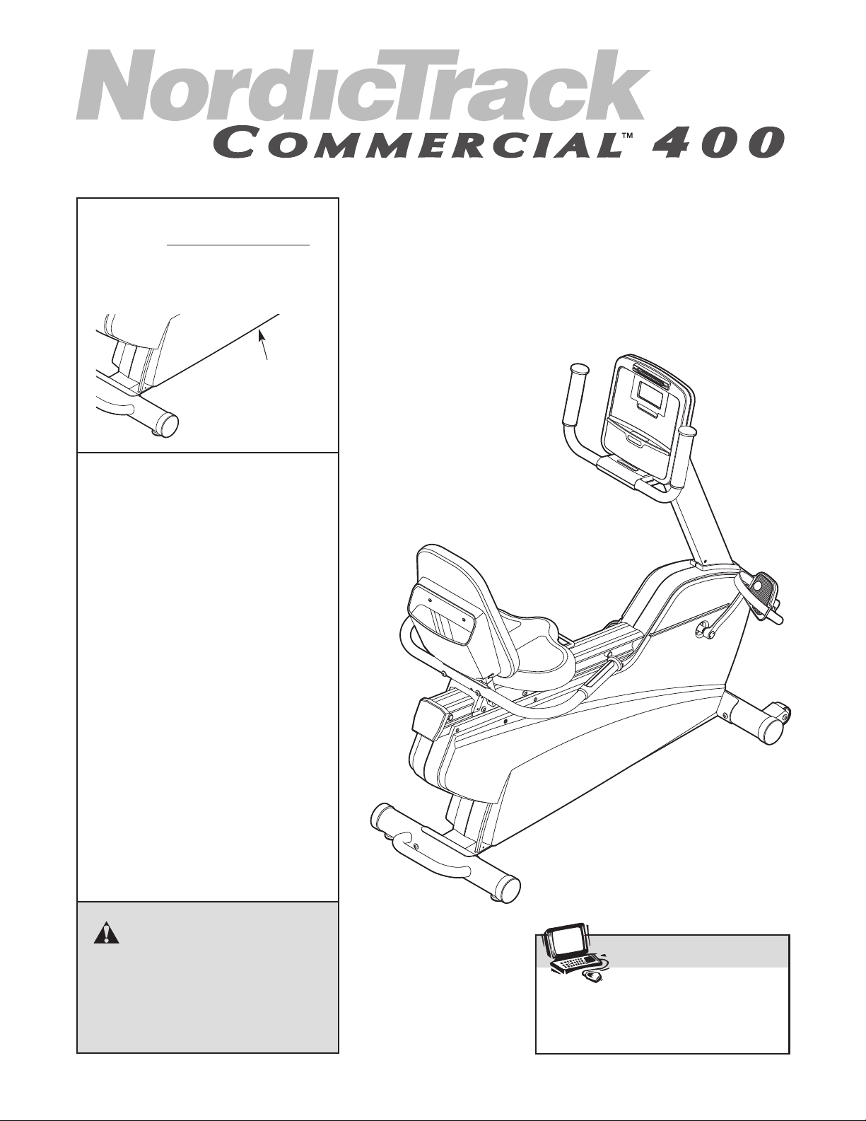
Model No. NTEX14807.0
Serial No.
Write the serial number in the
space above for reference.
Serial
Number
Decal
QUESTIONS?
As a manufacturer, we are committed to providing complete customer
satisfaction. If you have questions,
or if parts are damaged or missing,
PLEASE DO NOT CONTACT THE
STORE; please contact Customer
Care.
IMPORTANT: You must note the
product model number and serial
number (see the drawing above)
before contacting us:
USER'S MANUAL
CALL TOLL-FREE:
1-866-362-4490
Mon.–Fri. 6 a.m.–6 p.m. MST
Sat. 8 a.m.–4 p.m. MST
ON THE WEB:
www.nordictrackservice.com
CAUTION
Read all precautions and instructions in this manual before using
this equipment. Keep this manual
for future reference.
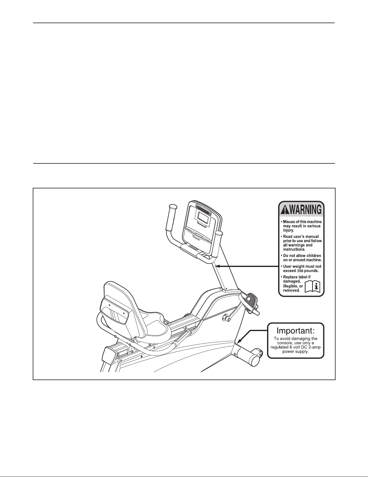
TABLE OF CONTENTS
WARNING DECAL PLACEMENT . . . . . . . . . . . . . . . . . . . . . . . . . . . . . . . . . . . . . . . . . . . . . . . . . . . . . . . . . . . . . .2
IMPORTANT PRECAUTIONS . . . . . . . . . . . . . . . . . . . . . . . . . . . . . . . . . . . . . . . . . . . . . . . . . . . . . . . . . . . . . . . .3
BEFORE YOU BEGIN . . . . . . . . . . . . . . . . . . . . . . . . . . . . . . . . . . . . . . . . . . . . . . . . . . . . . . . . . . . . . . . . . . . . . .4
ASSEMBLY . . . . . . . . . . . . . . . . . . . . . . . . . . . . . . . . . . . . . . . . . . . . . . . . . . . . . . . . . . . . . . . . . . . . . . . . . . . . . . .5
HOW TO OPERATE THE EXERCISE CYCLE . . . . . . . . . . . . . . . . . . . . . . . . . . . . . . . . . . . . . . . . . . . . . . . . . . .11
MAINTENANCE AND TROUBLESHOOTING . . . . . . . . . . . . . . . . . . . . . . . . . . . . . . . . . . . . . . . . . . . . . . . . . . .17
EXERCISE GUIDELINES . . . . . . . . . . . . . . . . . . . . . . . . . . . . . . . . . . . . . . . . . . . . . . . . . . . . . . . . . . . . . . . . . . .18
PART LIST . . . . . . . . . . . . . . . . . . . . . . . . . . . . . . . . . . . . . . . . . . . . . . . . . . . . . . . . . . . . . . . . . . . . . . . . . . . . . .21
EXPLODED DRAWING . . . . . . . . . . . . . . . . . . . . . . . . . . . . . . . . . . . . . . . . . . . . . . . . . . . . . . . . . . . . . . . . . . . .22
ORDERING REPLACEMENT PARTS . . . . . . . . . . . . . . . . . . . . . . . . . . . . . . . . . . . . . . . . . . . . . . . . . .Back Cover
LIMITED WARRANTY . . . . . . . . . . . . . . . . . . . . . . . . . . . . . . . . . . . . . . . . . . . . . . . . . . . . . . . . . . . . . .Back Cover
WARNING DECAL PLACEMENT
The warning decals shown here have
been applied in the locations shown. If
a decal is missing or illegible, call
the telephone number on the front
cover of this manual and request a
free replacement decal. Apply the
decal in the location shown. Note:
The decal may not be shown at actual
size.
NordicTrack is a registered trademark of ICON IP, Inc.
2

IMPORTANT PRECAUTIONS
WARNING: To reduce the risk of serious injury, read all important precautions and
instructions in this manual and all warnings on your exercise cycle before using your exercise
cycle. ICON assumes no responsibility for personal injury or property damage sustained by or
hrough the use of this product.
t
1. Before beginning any exercise program, consult your physician. This is especially important for persons over the age of 35 or persons with pre-existing health problems.
2. It is the responsibility of the owner to ensure
that all users of the exercise cycle are adequately informed of all precautions.
3. Your exercise cycle is intended for home use
only. Do not use your exercise cycle in a
commercial, rental, or institutional setting.
4. Keep your exercise cycle indoors, away from
moisture and dust. Place your exercise cycle
on a level surface, with a mat beneath it to
protect the floor or carpet. Make sure that
there is enough clearance around your exercise cycle to mount, dismount, and use it.
5. Inspect and properly tighten all parts regularly. Replace any worn parts immediately.
6. Keep children under age 12 and pets away
from your exercise cycle at all times.
8. The pulse sensor is not a medical device.
Various factors, including the user's movement, may affect the accuracy of heart rate
readings. The pulse sensor is intended only
as an exercise aid in determining heart rate
trends in general.
9. Wear appropriate exercise clothes while
exercising; do not wear loose clothes that
could become caught on your exercise cycle.
Always wear athletic shoes for foot protection while exercising.
10. Keep your back straight while using your
exercise cycle; do not arch your back.
11. When you stop exercising, allow the pedals
to slowly come to a stop.
12. If you feel pain or dizziness while exercising,
stop immediately and cool down.
13. Use your exercise cycle only as described in
this manual.
7. Your exercise cycle should not be used by
persons weighing more than 350 lbs.
(159 kg).
3
BEFORE YOU BEGIN
ongratulations for selecting the new NordicTrack
C
Commercial
most effective exercises for increasing cardiovascular
fitness, building endurance, and toning the entire body.
he NordicTrack Commercial 400 exercise cycle offers
T
an impressive array of features to let you enjoy this
healthful exercise in the convenience and privacy of
your home.
For your benefit, read this manual carefully before
you use the exercise cycle. If you have questions
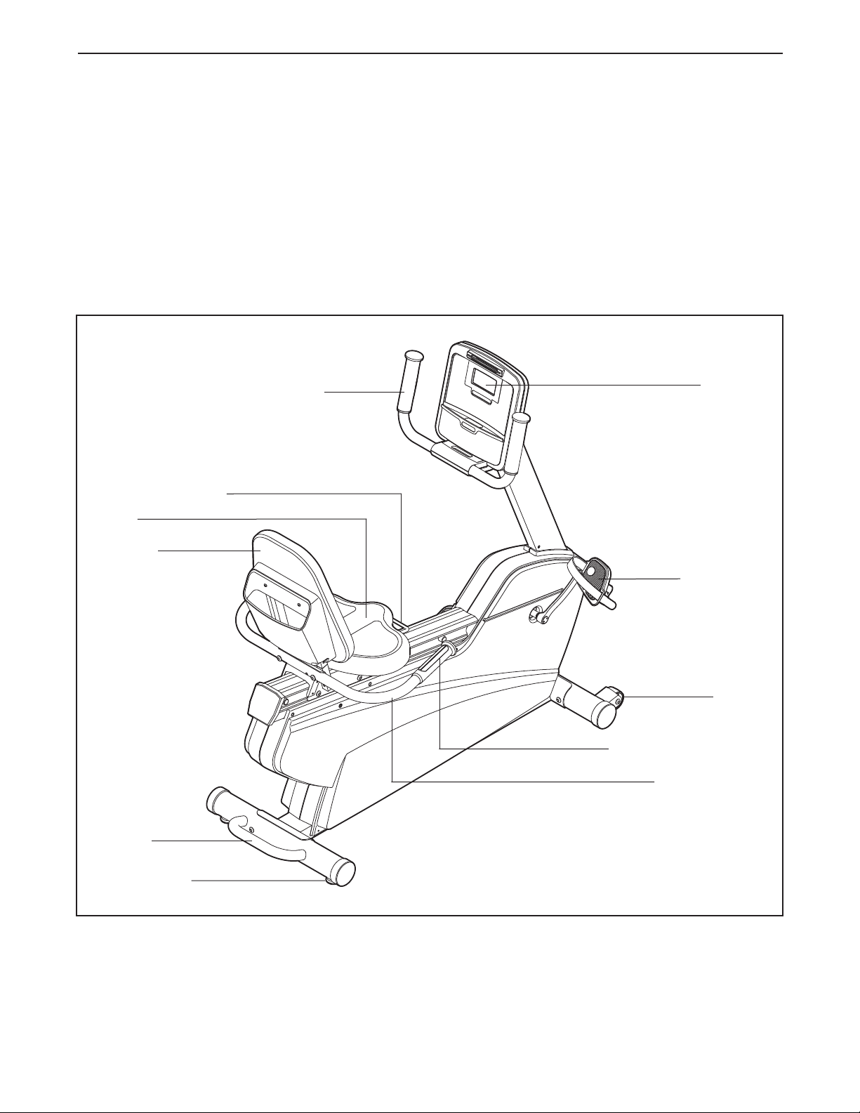
Adjustment Handle
Seat
™
400 exercise cycle. Cycling is one of the
Handlebar
fter reading this manual, please see the front cover
a
of this manual. To help us assist you, note the product
model number and serial number before contacting
us. The model number and the location of the serial
umber decal are shown on the front cover of this
n
manual.
Before reading further, please familiarize yourself with
the parts that are labeled in the drawing below.
Console
Backrest
Handle
Leveling Foot
Pedal/Strap
Wheel
Handgrip Pulse Sensor
Seat Handlebar
4
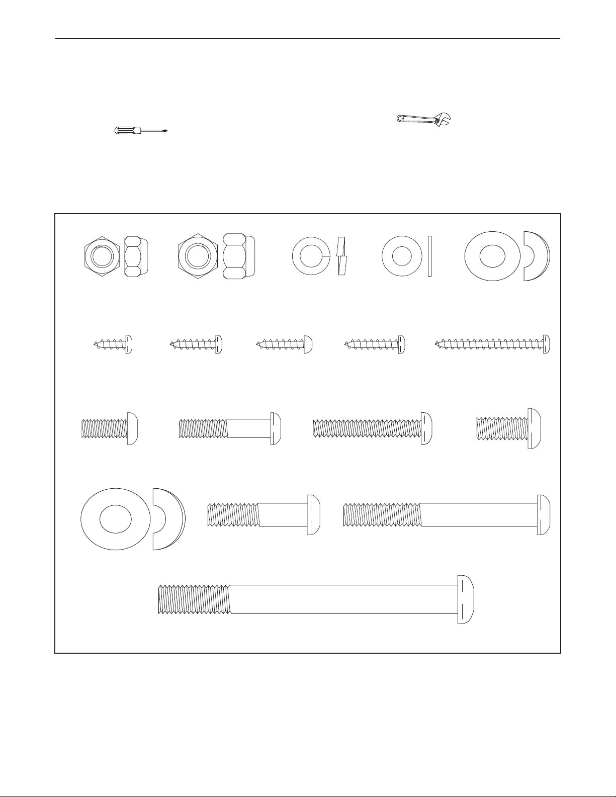
ASSEMBLY
M8 x 18mm Button
Screw (67)–4
M4 x 16mm
Round Head
Screw (68)–4
M8 x 68mm Button
Bolt (70)–2
M8 x 35mm Button
Bolt (72)–2
M6 x 32mm Button
Screw (69)–4
M6 x 16mm
Screw (71)–4
M4 x 19mm
Screw (75)–2
M4 x 38mm
Screw (89)–2
M4 x 12mm
Screw (101)–2
M10 Nylon
Locknut (91)–4
M8 Nylon
Locknut (99)–4
M8 Split
Washer (93)–6
M6 Washer
(88)–8
M8 Curved
Washer (86)–2
M10 x 94mm Button Bolt (65)–4
M4 x 16mm
Screw (77)–1
M10 Curved
Washer (94)–4
M6 x 38mm Button
Screw (25)–4
Assembly requires two persons. Place all parts of the exercise cycle in a cleared area and remove the packing
materials. Do not dispose of the packing materials until assembly is completed.
Assembly requires the included tools and your own adjustable wrench and Phillips
crewdriver .
s
Use the part drawings below to identify the small parts used in assembly. The number in parentheses below
each drawing is the key number of the part, from the PART LIST near the end of this manual. The number following the parentheses is the quantity needed for assembly. Note: Some small parts may have been preat-
tached. If a part is not in the hardware kit, check to see if it has been preattached.
5
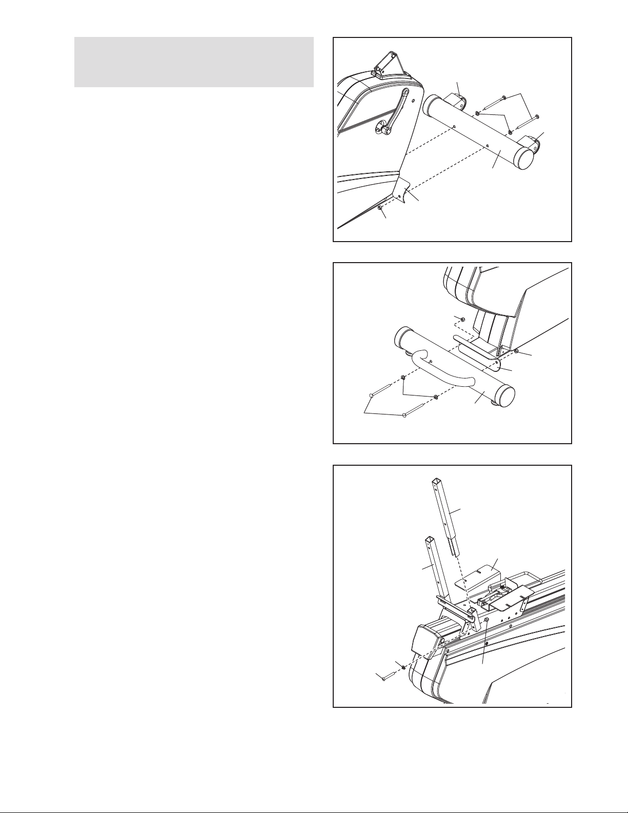
1.
To make assembly easier, read the
information on page 5 before you begin
ssembling the exercise cycle.
a
Orient the Front Stabilizer (15) with the Wheels (17)
positioned as shown. Attach the Front Stabilizer to
he Frame (1) with two M10 x 94mm Button Bolts
t
(65), two M10 Curved Washers (94), and two M10
Nylon Locknuts (91).
1
17
65
94
7
1
15
1
91
2. While another person lifts the rear of the Frame (1),
attach the Rear Stabilizer (16) to the Frame with
two M10 x 94mm Button Bolts (65), two M10
Curved Washers (94), and two M10 Nylon Locknuts
(91).
3. Orient a Backrest Tube (52) as shown. Insert the
Backrest Tube into a bracket on the Seat Carriage
(41). Attach the Backrest Tube with an M8 x 35mm
Button Bolt (72), an M8 Split Washer (93), and an
M8 Nylon Locknut (99). Make sure that the Nylon
Locknuts are in the hexagonal holes in the Seat
Carriage. Do not tighten the Button Bolt yet.
Repeat this step to attach the other Backrest
Tube (52).
2
91
91
1
94
65
3
52
16
52
41
93
72
99
6
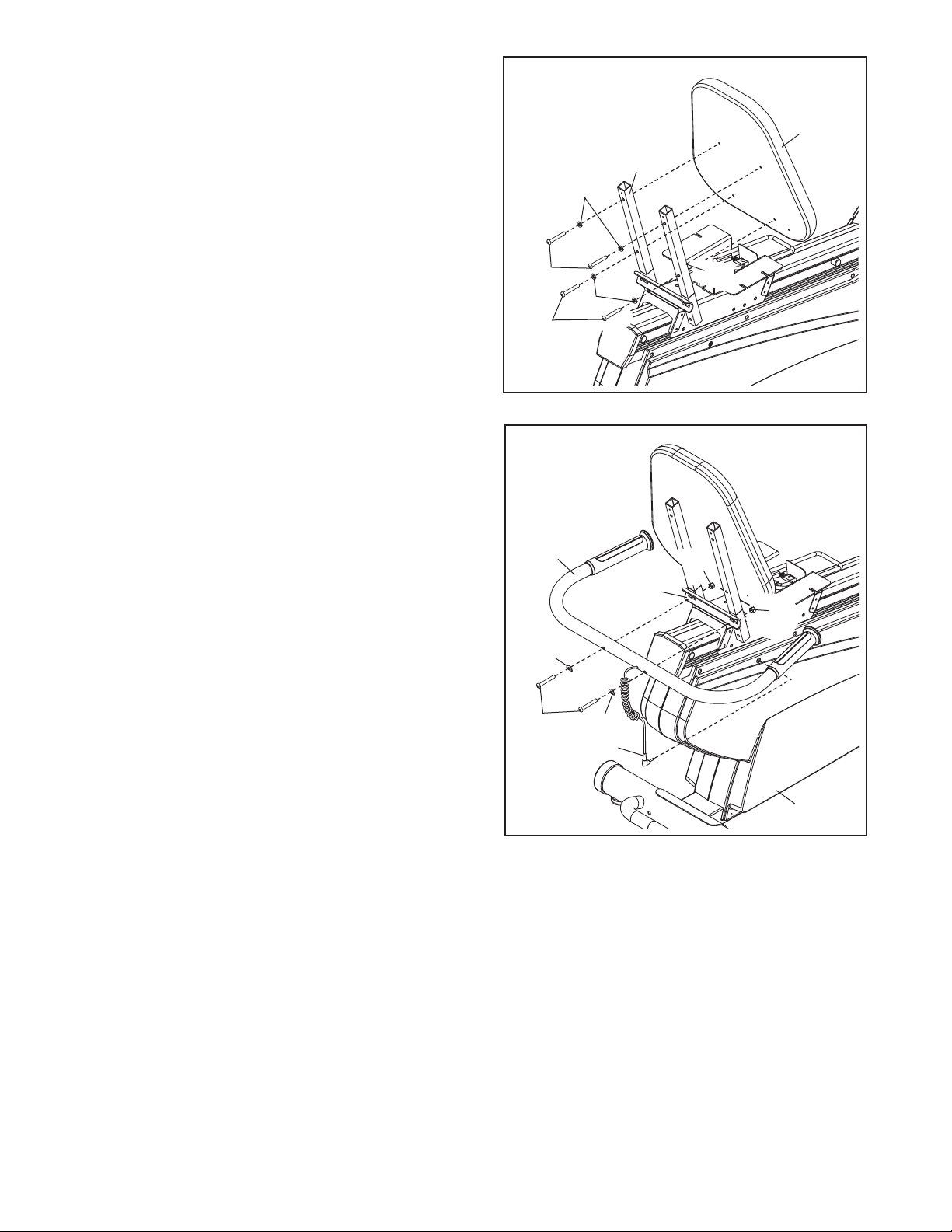
. Orient the Backrest (8) as shown. Attach the
4
Backrest to the Backrest Tubes (52) with four
M6 x 38mm Button Screws (25) and four M6
Washers (88).
4
8
2
5
8
8
5. Tip: Avoid damaging the wires inside the Seat
Handlebar (11) during this step.
Attach the Seat Handlebar (11) to the Seat Carriage
(41) with two M8 x 68mm Button Bolts (70), two M8
Curved Washers (86), and two M8 Nylon Locknuts
(99). Make sure that the Nylon Locknuts are in
the hexagonal holes in the Seat Carriage. Then,
plug the Lower Pulse Wire (58) into the receptacle
in the Right Side Shield (14).
See step 3. Tighten the two M8 x 35mm Button
Bolts (72).
25
88
25
5
11
41
86
70
86
58
52
99
99
14
7
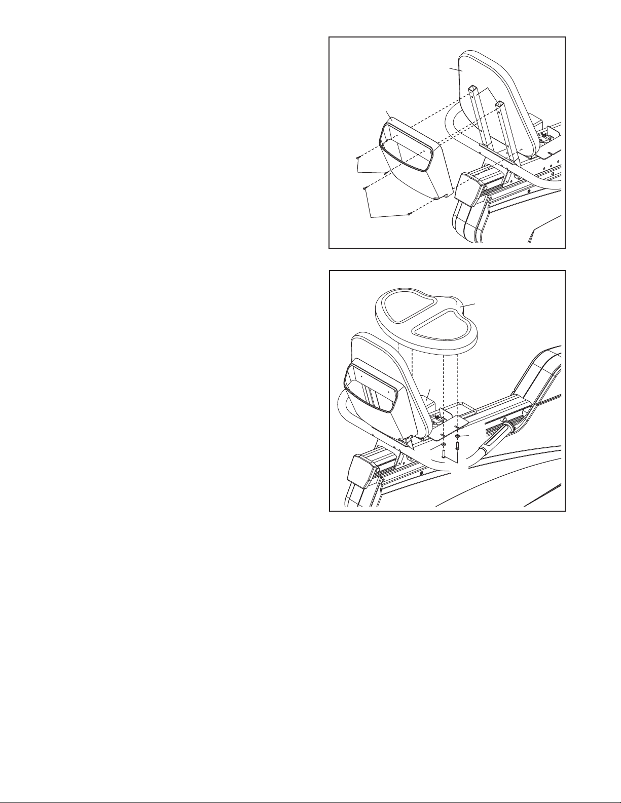
. Attach the Book Holder (3) to the Backrest Tubes
6
(52) with two M4 x 19mm Screws (75). Then, attach
the Book Holder to the Backrest (8) with two M4 x
38mm Screws (89).
6
8
52
3
75
89
7. Orient the Seat (9) as shown. Attach the Seat to the
Seat Carriage (41) with four M6 x 16mm Button
Screws (71) and four M6 Washers (88). Note: Only
two Screws and two Washers are shown.
7
9
41
88
88
71
8
 Loading...