

Page 1

PAMS Technical Documentation
NSE–8/9 Series Transceivers
Service Tools
Issue 1 07/99
Page 2

NSE–8/9
PAMS
Service Tools
CONTENTS
Service Interface Cable TDS–7 3. . . . . . . . . . . . . . . . . . . . . . . . . . . . . . . . .
Module Jig MJS–13 4. . . . . . . . . . . . . . . . . . . . . . . . . . . . . . . . . . . . . . . . . . .
Flash Loading Adapter FLA–5 (Sales Pack) 5. . . . . . . . . . . . . . . . . . . . . .
Flash Prommer FPS–4S (Sales Pack) 6. . . . . . . . . . . . . . . . . . . . . . . . . . .
Security Box TDF–4 7. . . . . . . . . . . . . . . . . . . . . . . . . . . . . . . . . . . . . . . . . . .
Service Audio Box JBA–4 8. . . . . . . . . . . . . . . . . . . . . . . . . . . . . . . . . . . . . .
Modular Cable XMS–3 9. . . . . . . . . . . . . . . . . . . . . . . . . . . . . . . . . . . . . . . . .
Warranty Transfer Tool SCW–1 10. . . . . . . . . . . . . . . . . . . . . . . . . . . . . . . . .
Audio Cable ADS–1 11. . . . . . . . . . . . . . . . . . . . . . . . . . . . . . . . . . . . . . . . . . .
D15–D15 Cable AXS–5 12. . . . . . . . . . . . . . . . . . . . . . . . . . . . . . . . . . . . . . . .
DC Cable PCC–1B 13. . . . . . . . . . . . . . . . . . . . . . . . . . . . . . . . . . . . . . . . . . . .
RF Coaxial Test Cable 14. . . . . . . . . . . . . . . . . . . . . . . . . . . . . . . . . . . . . . . . .
Technical Documentation
Page No
MBUS Cable DAU–9S 15. . . . . . . . . . . . . . . . . . . . . . . . . . . . . . . . . . . . . . . . .
Audio Test Cable SCB–5 16. . . . . . . . . . . . . . . . . . . . . . . . . . . . . . . . . . . . . . .
Power Cable PCS–1 17. . . . . . . . . . . . . . . . . . . . . . . . . . . . . . . . . . . . . . . . . . .
Modular T–adapter 18. . . . . . . . . . . . . . . . . . . . . . . . . . . . . . . . . . . . . . . . . . . .
SW Security Device PKD–1 19. . . . . . . . . . . . . . . . . . . . . . . . . . . . . . . . . . . .
Dongle/Flash Device FLS–1 (Sales Pack) 20. . . . . . . . . . . . . . . . . . . . . . . .
Page 2
Issue 1 07/99
Page 3

PAMS
NSE–8/9
Technical Documentation
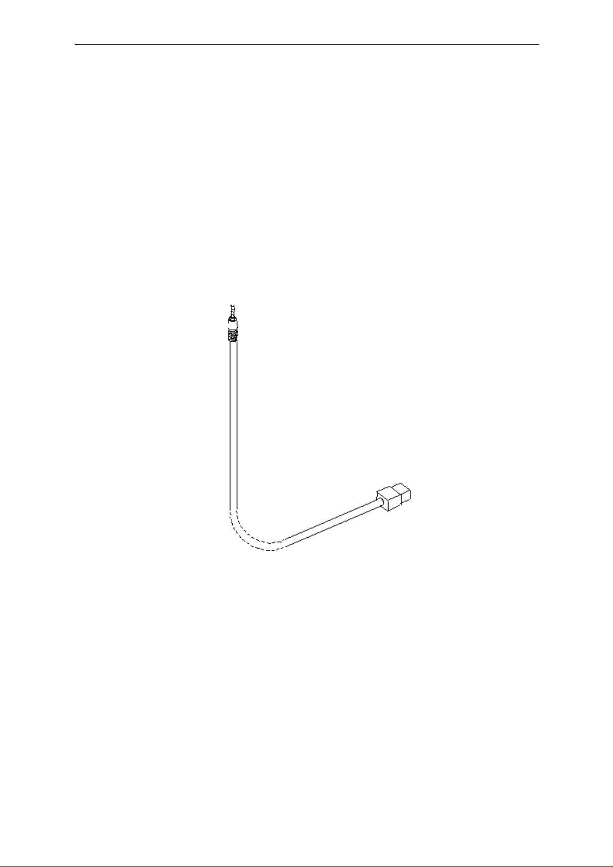
Service Interface Cable TDS–7
The Service interface cable is used to flash and tune the phone without
disassembling it.
Product Code
Service Interface Cable TDS–7: 07750160
View of TDS–7
Service Tools
Note: The nominal supply voltage forTDS–7 is 9–15VDC
Issue 1 07/99
Page 3
Page 4

NSE–8/9
PAMS
Service Tools
Module Jig MJS–13
The Module Jig MJS–13 is used for component level repair of the system
module.
Product Code
Module Jig MJS–13: 0770158
View of MJS–13
Technical Documentation
Page 4
Note: The nominal supply voltagerange for MJS–13 is 9–15 V.
Issue 1 07/99
Page 5

PAMS
NSE–8/9
Technical Documentation
Flash Loading Adapter FLA–5 (Sales Pack)
The Flash Loading Adapter FLA–5 is used with the Service Battery BBD–3
and Service Cable SCH–5. Power is supplied to FLA–5 from the Flash
Security Box TDF–4 via the DC cable PCC–1B, (The PCC–1B cable can
be replaced with a Travel Charger ACH–6), and is connected to the Flash
Prommer FPS–4S with the cable AXS–5.
The sales pack includes:
– Flash Loader Adapter FLA–5 0770085
– Service cable SCH–5 0730098
– D15 – D15 Cable AXS–5 0730091
– Installation software for FPS–4 8400041
Product Code
Flash Loading Adapter FLA–5: 0770085
View of FLA–5
Service Tools
Issue 1 07/99
Page 5
Page 6

NSE–8/9
PAMS
Service Tools
Flash Prommer FPS–4S (Sales Pack)
The Flash Prommer FPS–4S is used to update the main software of the
phone. Updating is done by first loading the new MCU software from the
PC to the flash prommer, and then loading the new SW from the prommer
to the phone. When updating more than one phone in succession, the
MCU software only needs to be loaded to the prommer once.
The sales pack includes:
– Charger ACL–3E 0680015
– Printer Cable 0730029
– D9 – D9 Cable AXS–4 0730090
– Installation software for FPS–4 8400041
Product Code
Flash Prommer FPS–4: 0750090
View of FPS–4S
Technical Documentation
Page 6
Issue 1 07/99
Page 7

PAMS
NSE–8/9
Technical Documentation
Security Box TDF–4
The Security Box TDF–4 is required for updating MCU software, and infra
red testing.
Note1: TDF–4 is delivered in de–activated mode. Fill in the enclosed
Activation Request Form, and fax to NMP Salo to get the
activation code
Note2: The infra red module JLP–1 is not included in the TDF–4 sales
package
Product Code
Security Box TDF–4: 0770106
View of TDF–4
Service Tools
Issue 1 07/99
Page 7
Page 8

NSE–8/9
PAMS
Service Tools
Service Audio Box JBA–4
The Service Audio Box JBA–4 is used between the module repair jig
MJS–13 and audio test cables SCB–5 and ADS–1.
Product Code
Service Audio Box JBA–4: 0770094
View of JBA–4
Technical Documentation
Page 8
Issue 1 07/99
Page 9

PAMS
NSE–8/9
Technical Documentation
Modular Cable XMS–3
The modular cable is used to connect the TDS–7 or MJS–13 to the FLA–5
(or 7) flash loading adapter. This enables flashing of the phone.
The XMS–3 is also used when flashing with the Point Of Sales (POS)
device FLS–2.
Product Code
Modular Cable XMS–3: 0730174
View of XMS–3
Service Tools
Issue 1 07/99
Page 9
Page 10

NSE–8/9
PAMS
Service Tools
Warranty Transfer Tool SCW–1
The Warranty Transfer Tool is used to connect two phones and enables
transfer of user data (picture messages,T9 user dictionary etc.) from one
phone to another.
Two tools are required to perform Warranty Transfer.
The tool is also used for the Point Of Sales (POS) flash device
FLS–2.
Product Code
Warranty Transfer Tool SCW–1 0770161
View of SCW–1
Technical Documentation
Page 10
Issue 1 07/99
Page 11

PAMS
NSE–8/9
Technical Documentation
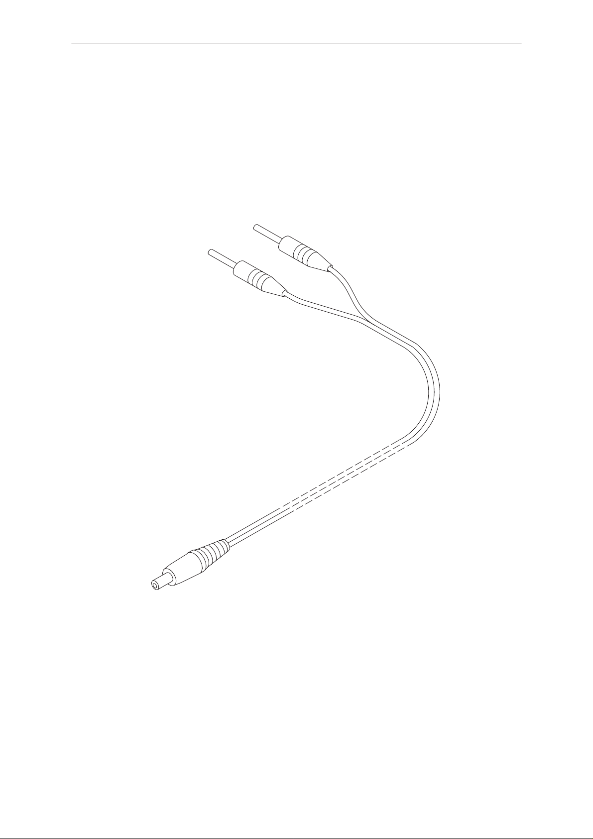
Audio Cable ADS–1
Audio cable is an adapter routing AF signals (MIC/EAR) from an 8 pin
modular connector to two BNC connectors.
Product code
Audio Cable ADS–1: 0730011
View of ADS–1
Service Tools
Issue 1 07/99
Page 11
Page 12

NSE–8/9
PAMS
Service Tools
D15–D15 Cable AXS–5
The D15–D15 Cable AXS–5 is used to connect two 15 pin D connectors.
e.g. between FLA–5 and FPS–4S.
Product Code
D15–D15 Cable AXS–5: 0730091
View of AXS–5
Technical Documentation
Page 12
Issue 1 07/99
Page 13

PAMS
NSE–8/9
Technical Documentation
DC Cable PCC–1B
The DC Cable PCC–1B is used e.g. to connect FLA–5 and TDF–4.
Product Code
DC Cable PCC–1B: 0770053
View of PCC–1
Service Tools
Issue 1 07/99
Page 13
Page 14

NSE–8/9
PAMS
Service Tools
RF Coaxial Test Cable
The RF Coaxial cable is used to connect the transceiver to external
measuring equipment during servicing.
Note: Typical attenuation at 900MHz is 0.9dB (with MJS–13 & TDS–7)
Typical attenuation at 1800MHz is 1.45dB (with MJS–13 & TDS–7)
Product Code
RF Coaxial Cable 4626009
View of RF–Coax Test Cable
Technical Documentation
Page 14
Issue 1 07/99
Page 15

PAMS
NSE–8/9
Technical Documentation
MBUS Cable DAU–9S
The MBUS Cable DAU–9S has a modular connector, and is used for data
communication with the phone for connecting TDS–7 and MJS–13 to a
PC.
MBUS Cable DAU–9S: 0730108
View of DAU–9S
Service Tools
Issue 1 07/99
Page 15
Page 16
NSE–8/9
PAMS
Service Tools
Audio Test Cable SCB–5
The Audio Test Cable is used to connect the phones headset to the
Service Audio Box JBA–4, supplying Mic/Ear signals to external test
devices.
MBUS SCB–5: 0775211
View of SCB–5
Technical Documentation
Page 16
Issue 1 07/99
Page 17
PAMS
NSE–8/9
Technical Documentation
Power Cable PCS–1
The Power Cable PCS–1 is used to connect the module jigs MJS–13 and
service interface TDS–7 to an external power supply.
Product Code
Power Cable PCS–1: 0730012
View of PCS–1
Service Tools
Issue 1 07/99
Page 17
Page 18

NSE–8/9
PAMS
Service Tools
Modular T–adapter
The modular T–adapter is a suitable branching unit to provide the needed
parallel modular connections.
Used for warranty transfer between two phones.
Product Code
Modular T–adapter: 4626134
View of Modular T–adapter
Technical Documentation
Page 18
Issue 1 07/99
Page 19

PAMS
NSE–8/9
Technical Documentation
SW Security Device PKD–1
SW security device is a piece of hardware enabling the use of the service
software when connected to the parallel (LPT) port of the PC. Whitout the
dongle present it is not possible to use the service software. Printer or any
such device can be connected to the PC through the dongle if needed.
Caution: Make sure thet you have switched off the PC and the printer
before making connections!
Caution: Do not connected the PKD–1 to the serial port. You may
damage your PKD–1!
Product Code
SW Security Device PKD–1: 0750018
View of SW Security Device
Service Tools
Issue 1 07/99
Page 19
Page 20

NSE–8/9
БББББББББББББББББББББББ
БББББББББББББББББББББББ
БББББББББББББББББББББББ
БББББББББББББББББББББББ
БББББББББББББББББББББББ
БББББББББББББББББББББББ
БББББББББББББББББББББББ
Á
БББББББББББББББББББББББ
Á
Á
Á
БББББББББББББББББББББББ
Á
Á
PAMS
Service Tools
Dongle/Flash Device FLS–1 /2 (Sales Pack)
FLS–1/2 are dongle and flash devices incorporated into one package,
developed specifically for POS use.
Product Code
FLS–1 Sales Pack –APAC 0081290
FLS–1 Sales Pack – Europe/Africa 0081291
FLS–2 Sales Pack –APAC/Europe /APAC 0081311
View of FLS–1 /2
Technical Documentation
Sales Pack Contents
Part No.
0750130
0730163
0770177
0770176
0774120
0774123
0275405
ÁÁÁ
0275404
ÁÁÁ
FLS–1 Flash Device.
AXS–4U Cable.
Disk– Installation package,16bit Dongle Drivers.
Disk – Installation package, 32bit Dongle Drivers.
Disk – Installation package for the FLE–5 Drivers.
Disk – Remote Update Application Installation Package.
Installation and User Guide
БББББББББББББББББББББ
Registration Request Form
БББББББББББББББББББББ
The picture overleaf shows how to connect the FLS–1 and 2 devices
and associated cables to the PC and Product/Phone.
Description
Page 20
Issue 1 07/99
Page 21

PAMS
)
NSE–8/9
Technical Documentation
FLS–1 Connection Diagram with TDS–7
Note: TDS–7 required to flash with FLS–1
4
1
3
2
Service Tools
1.
FLS–1 (connects to
2 TDS–7
3
AXS–4U
PC with WinTesla Software
4
parallel port
FLS–2 Connection Diagram with SCW–1
Note: With SCW–1, flashing requires just a phone with battery
4
1
2
FLS–2 connects to parallel port
1
2
SCW–1 Flash & Warranty
transfer tool
3 AXS–4U
PC with WinTesla
4
software
Issue 1 07/99
3
Page 21
Page 22

NSE–8/9
PAMS
Service Tools
Technical Documentation
[This page intentionally left blank]
Page 22
Issue 1 07/99
 Loading...