

Page 1

CCS Technical Documentation
RH-17 Series Transceivers
Service Tools
Issue 1 04/2003 Confidential Nokia Corporation
Page 2

RH-17
Service Tools CCS Technical Documentation
Page 2 Nokia Corporation Confidential Issue 1 04/2003
Page 3

RH-17
CCS Technical Documentation Service Tools
Contents
Page No
Service Tools.................................................................................................................. 5
2280 .............................................................................................................................5
Flashing and Testing Setups ........................................................................................ 11
Service Case #1 ..........................................................................................................11
Service Case #2 ..........................................................................................................12
Service Case #3 ..........................................................................................................13
Service Case #4 ..........................................................................................................14
Issue 1 04/2003 Nokia Corporation Confidential Page 3
Page 4

RH-17
Service Tools CCS Technical Documentation
Page 4 Nokia Corporation Confidential Issue 1 04/2003
Page 5
RH-17
CCS Technical Documentation Service Tools
Service Tools
2280
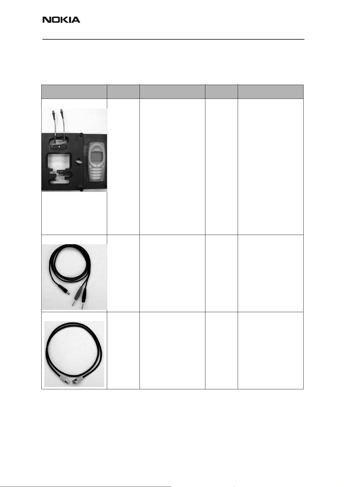
Photo Code Service Tool Code Description Info
MJS-82 Service Jig 0770474 MJS-82 secures and
allows easy access to
critical areas of the handset’s PWB during troubleshooting. It supports
regulated and unregulated DC input voltages,
Local and Normal mode
operations, headset jack
for audio tests, R-UIM
card reader, second DC
input for VCHAR used in
EM tuning. This jig also
supports simultaneous RF
connections to the CDMA
and GPS engines. A completely functional UI
module is provided on the
right side.
PCS-1 DC Cable 0730012 The Power Cable PCS-1 is
used to connect the service tools (JBV-1, MJS-57)
to an external power supply.
XCS-4 Service Cable 0730178 The XCS-4 Service Cable
is a modular cable for
flashing DCT4 products.
Issue 1 04/2003 Nokia Corporation Confidential Page 5
Page 6

RH-17
Service Tools CCS Technical Documentation
Photo Code Service Tool Code Description Info
RJ-13 Rework Jig 0770574 This tool serves as a
mechanical PWB holder
for desoldering and soldering of components.
This tool is NOT intended
to serve as a test jig.
MJF-28 Docking Station Adapter 0770484 This device works in con-
junction with JBV-1
Docking Station and the
FPS-8 Prommer Box to
allow calibration, tuning,
and/or software flashing
of the handset. It supports the LYNX battery
interface, which does not
require BTEMP. It also has
a built-in R-UIM card
reader. The MJF device is
used in AMS repair centers for flashing and tuning. It is also useful in
R&D labs during product
development and True
Testing.
CA-5S DC Service Cable 0730283 CA-5S is used for EM
calibration with the
JBV-1. The cable replaces
the SCB-3 DC Cable
(0730114).
FLA-44 Flash Loading Adapter 0770483 This accessory replaces
the phone battery and
allows the service SW to
communicate with the
handset for flashing and
other POS functions using
the FLS-4S device setup.
The device can also be
powered by an external P/
S (3.9-4.5 VDC...DO NOT
exceed 4.5.VDC). Pins
(0770450) are replaceable
as long as they do not get
stuck inside the PIN
tower.
Page 6 Nokia Corporation Confidential Issue 1 04/2003
Page 7

RH-17
CCS Technical Documentation Service Tools
Photo Code Service Tool Code Description Info
SKT-3 Test A-Cover 0770541 The SKT-3 A-cover allows
the technician to replace
the handset’s original Acover with one that provides access to the CDMA
and GPS RF connectors.
The test A-cover is best
suited for test cases
where UI (keypad + LCD)
functionality is required.
SKT-3 only supports the
XRS-4 RF test cable.
XRS-4 RF Test Cable 0730221 Use with the SKT-3 A-
cover.
SA-9 RF Support 0770564 The RF Support and
Spring-loaded RF Cable
solution is an alternative
to the Test A-cover (SKT-
3). It is best suited to test
cases where UI functionality is not required and
repetitive tests are
needed (e.g., tuning and
calibrating multiple
phones). This setup takes
advantage of the holes
provided in the UI light
guide for RF connections.
The A-cover must be
removed when using this
tool.
CA-8RS RF Test Cable 0730299 The RF Support and
Spring-loaded RF Cable
solution is an alternative
to the Test A-cover (SKT-
3). It is best suited to test
cases where UI functionality is not required and
repetitive tests are
needed (e.g., tuning and
calibrating multiple
phones). This setup takes
advantage of the holes
provided in the UI light
guide for RF connections.
The A-cover must be
removed when using this
tool.
Issue 1 04/2003 Nokia Corporation Confidential Page 7
Page 8

RH-17
Service Tools CCS Technical Documentation
Photo Code Service Tool Code Description Info
JBV-1 Docking Station 0770298 The Docking Station and
the Docking Station
Adapter are needed for
Mbus, Fbus, RF, and audio
connections.
This setup allows connection between flash prommers. When the audio box
is connected, it has to be
connected to the phone’s
audio connector. The
Docking Station can be
powered by FPS-8 or
external power supply.
FPS-8 Prommer Box 0080321 The Flash Prommer FPS-8
is used for heavy flash.
JXS-1 Shield Box N/A Developed by and used by
the Americas AMS group.
PKD-1XX SW Protection Key (don-
gles)
0750018
(PDK-1)
Allows Nokia Service SW
(e.g., Phoenix, Diego) to
function and perform
specific features. Not for
use outside of Nokia
facilities.
Page 8 Nokia Corporation Confidential Issue 1 04/2003
Page 9

RH-17
CCS Technical Documentation Service Tools
Photo Code Service Tool Code Description Info
FLS-4S POS Flash Adapter 0080543 The Point of Sale (POS)
flash is a low-cost software upgrade tool. This
requires the XCS-1 cable
and ACP-8U for operation.
DAU-9T FBUS Cable 0730267 The FBUS cable DAU-9T
provides a connection
from the serial port of the
computer to the system
connector of the phone.
DAU-9S Service Cable 0720167 This general-purpose
cable supports F/M-BUS
communication between
a Mod-10 device and a
PC.
DKU-5F Flash Cable 0730281 The flash adapter allows
FBUS connections over
USB pop port when using
Spirent UPST for flashing.
Note: The cable cannot be
used as a straightthrough USB connection
cable.
Issue 1 04/2003 Nokia Corporation Confidential Page 9
Page 10

RH-17
Service Tools CCS Technical Documentation
Flashing and Testing Setups
Service Case #1
This setup is best suited for Point of Sale (POS) locations using Diego Service Software.
The picture below shows the FLA-44 device attached to the handset. Power is provided to
the FLA-44 by the FLA-4S flashing device, which in turn is powered by an external power
supply. The FLS-4S device connects to the parallel port of the PC running the Diego
application.
Page 10 Nokia Corporation Confidential Issue 1 04/2003
Page 11

RH-17
CCS Technical Documentation Service Tools
Service Case #2
This setup illustrates an MJF-28 with a Haukka handset together with a Test A-cover and
two XRS-4 RF test cables. This application could be used during testing and/or troubleshooting where the UI functionality of the handset is required for such tests.
For repetitive tests, the SA-9 and RF cable solution configuration (Service Case #3) is a
better solution since it eliminates the time it takes to place the Test A-cover.
Issue 1 04/2003 Nokia Corporation Confidential Page 11
Page 12

RH-17
Service Tools CCS Technical Documentation
Service Case #3
This configuration shows an MJF-28 with a Haukka handset and two SA-9 RF supports
plus two CA-8RS RF test cables. This application could be used during RF calibration, and
for CE and GPS testing.
This is an easy and secure method of performing the same tests the Test A-cover solution
provides, but it is best suited for repetitive testing.
Page 12 Nokia Corporation Confidential Issue 1 04/2003
Page 13

RH-17
CCS Technical Documentation Service Tools
Service Case #4
This setup illustrates the MJS-82 with XRS-4 RF test cables, connected to an FPS-8
prommer box. This setup allows troubleshooting and flashing of the engine at the same
time.
The jig also could be connected directly to the PC running Phoenix, using the general
purpose DAU-9S cable.
Issue 1 04/2003 Nokia Corporation Confidential Page 13
Page 14

RH-17
Service Tools CCS Technical Documentation
Page 14 Nokia Corporation Confidential Issue 1 04/2003
 Loading...