

Page 1

Customer Care Solutions
Technical Documentation
SERVICE
MANUAL
[NMP Part No. 0275725]
Models 2285, 2270, 2275
(RH-3 Series) Cellular Phones
Issue 1 Copyright Nokia Corporation. All Rights Reserved
Page 2

Customer Care Solutions
Technical Documentation
Amendment Record Sheet
Amendment No Date Inserted By Comments
06/2003 J Fraser Issue 1
Issue 1 Copyright Nokia Corporation. All Rights Reserved
Page 3

Customer Care Solutions
Technical Documentation
RH-3 (2285, 2270, 2275) Cellular Phones
Service Manual – Overall Manual Contents
Service Manual comprising
RH-3 Series Transceiver booklet comprising
Foreword
General
Parts
Service Software Instructions
Service Tools
Disassembly/Assembly
Troub leshoo ting - Antennas
Troubleshoo ting - Baseband
Troub leshoo ting - RF
Troub leshoo ting - GPS
System Module
Schematics
Issue 1 Copyright Nokia Corporation. All Rights Reserved
Page 4

This document is intended for use by qualified service personnel only.
Company Policy
Our policy is of continuous development; details of all technical modifications will be
included with service bulletins.
While every endeavour has been made to ensure the accuracy of this document, some
errors may exist. If any errors are found by the reader, NOKIA Corporation should be
notified in writing.
Please state:
Customer Care Solutions
Technical Documentation
IMPORTANT
Title of the Document + Issue Number/Date of publication
Latest Amendment Number (if applicable)
Page(s) and/or Figure(s) in error
Please send to: Nokia Corporation
CCS Technical Documentation
PO Box 86
FIN-24101 SALO
Finland
Issue 1 Copyright Nokia Corporation. All Rights Reserved
Page 5

Customer Care Solutions
Technical Documentation
Warnings and Cautions
Please refer to the phone's user guide for instructions relating to operation, care and
maintenance including important safety information. Note also the following:
Warnings:
1. CARE MUST BE TAKEN ON INSTALLATION IN VEHICLES FITTED WITH
ELECTRONIC ENGINE MANAGEMENT SYSTEMS AND ANTI-SKID BRAKING
SYSTEMS. UNDER CERTAIN FAULT CONDITIONS, EMITTED RF ENERGY CAN
AFFECT THEIR OPERATION. IF NECESSARY, CONSULT THE VEHICLE DEALER/
MANUFACTURER TO DETERMINE THE IMMUNITY OF VEHICLE ELECTRONIC
SYSTEMS TO RF ENERGY.
2. THE HANDPORTABLE TELEPHONE MUST NOT BE OPERATED IN AREAS LIKELY
TO CONTAIN POTENTIALLY EXPLOSIVE ATMOSPHERES EG PETROL STATIONS
(SERVICE STATIONS), BLASTING AREAS ETC.
3. OPERATION OF ANY RADIO TRANSMITTING EQUIPMENT, INCLUDING
Cautions:
1. Servicing and alignment must be undertaken by qualified personnel only.
2. Ensure all work is carried out at an anti-static workstation and that an
3. Ensure solder, wire, or foreign matter does not enter the telephone as
4. Use only approved components as specified in the parts list.
5. Ensure all components, modules screws and insulators are correctly
CELLULAR TELEPHONES, MAY INTERFERE WITH THE FUNCTIONALITY OF
INADEQUATELY PROTECTED MEDICAL DEVICES. CONSULT A PHYSICIAN OR
THE MANUFACTURER OF THE MEDICAL DEVICE IF YOU HAVE ANY
QUESTIONS. OTHER ELECTRONIC EQUIPMENT MAY ALSO BE SUBJECT TO
INTERFERENCE.
anti-static wrist strap is worn.
damage may result.
re-fitted after servicing and alignment. Ensure all cables and wires are
repositioned correctly.
Issue 1 Copyright Nokia Corporation. All Rights Reserved
Page 6

CCS Technical Documentation
RH-3 Series Transceivers
General Information
Issue 1 06/2003 Confidential Nokia Corporation
Page 7

RH-3
General Information CCS Technical Documentation
Page 2 Nokia Corporation Confidential Issue 1 06/2003
Page 8

RH-3
CCS Technical Documentation General Information
Contents
Page No
Product Selection ........................................................................................................... 5
Handportables ..............................................................................................................5
Sales Package ...............................................................................................................5
Supported Accessories................................................................................................... 7
Issue 1 06/2003 Nokia Corporation Confidential Page 3
Page 9

RH-3
General Information CCS Technical Documentation
Page 4 Nokia Corporation Confidential Issue 1 06/2003
Page 10
RH-3
CCS Technical Documentation General Information
Product Selection
The current RH-3 family includes Model 2285 (RH-3), Model 2270 (RH-3P), and
Model 2275 (RH-3DNG).
Model 2285 is a CDMA dual-mode engine (1900/800 MHz CDMA), supporting the CDMA
1XRTT Standard Air Interface. In addition, Model 2285 includes a built-in GPS engine
(GE) for E-911 emergency services.
Model 2270 is a PCS single-band CDMA 1900 engine, including a built-in GPS engine
(GE) for E-911 emergency services.
Model 2275 is a dual-band (PCS and Cell) engine. No GPS support is provided.
Note: The RH-3 family does NOT support AMPS.
The RH-3 family uses the following antennas:
• Planar Internal “F” Antenna (PIFA) - Models 2285, 2270, 2275
• External, extendable “whip” - Models 2285, 2270, 2275
• Global Positioning System (GPS) - Models 2285, 2270 only
When the whip antenna is in, only the internal antenna (PIFA) is active. When the whip is
extended, both antennas are active. Access for testing cellular and GPS engines is possible once the A-cover is removed.
RH-3 features include an internal vibra, high-resolution display (96x65 pixels), a 2.5 mm
Universal headset connector with TTY/TDD support, GPS technology (Model 2285 and
2270), T9 predictive text input, and voice dialing , etc.
Issue 1 06/2003 Nokia Corporation Confidential Page 5
Page 11
RH-3
General Information CCS Technical Documentation
Sales Package
Name: Type Code: Material Code:
Transceiver RH-3/RH-3P/RH-3DNG Customer specific
Battery (850 mAh Li-Ion) BLC-5C 0670398
Rapid Performance Charger (US plug) ACP-7U 0675143
Supported Accessories
Type Name Code
BL-5C Standard 850 mAh Li-ion Battery 0670398
ACP-7U AC Travel Charger (US) 108-132 Vac 0675143
ACP-8U AC Charger 0675196
ACP-12U Rapid Performance Charger (US) 0675303
DCV-15 Desk stand with one-
button synchronization
CARK142 Advanced Car Kit with passive handset 0080685
BHF-1 Headrest handsfree 0273278
LPS-4 Loopset 0630443
LCH-9 Cigarette Lighter Charger 0675120
HDB-4 Boom Headset 0694094
DKU-5 USB cable 0273870
0675326
Page 6 Nokia Corporation Confidential Issue 1 06/2003
Page 12

CCS Technical Documentation
RH-3 Series Transceivers
Parts Lists
Issue 1 06/2003 Confidential Nokia Corporation
Page 13

RH-3
Parts Lists CCS Technical Documentation
Page 2 Nokia Corporation Confidential Issue 1 06/2003
Page 14

RH-3
CCS Technical Documentation Parts Lists
Contents
Page No
Exploded View............................................................................................................... 5
Assembly Parts List .....................................................................................................5
D-cover Assembly .......................................................................................................6
D-cover Assembly Parts List .......................................................................................6
Model 2285.................................................................................................................... 7
Component Layout - Top .............................................................................................7
Component Layout - Bottom .......................................................................................8
RH-3 (2285) — EDMS Issue 2.59 Code: 0202057 .....................................................9
Shield Can Lid Part Codes...................................................................................... 23
Model 2270.................................................................................................................. 24
Component Layout - Top ...........................................................................................24
Component Layout - Bottom .....................................................................................25
RH-3P (2270) — EDMS Issue 3.49 Code: 0202081 .................................................26
Shield Can Lid Part Codes...................................................................................... 39
Model 2275.................................................................................................................. 40
Component Layout - Top ...........................................................................................40
Component Layout - Bottom .....................................................................................41
RH-3DNG (2275) — EDMS Issue 3.2 Code: 0202107 ............................................42
Shield Can Lid Part Codes...................................................................................... 53
Issue 1 06/2003 Nokia Corporation Confidential Page 3
Page 15

RH-3
Parts Lists CCS Technical Documentation
Page 4 Nokia Corporation Confidential Issue 1 06/2003
Page 16
RH-3
r
CCS Technical Documentation Parts Lists
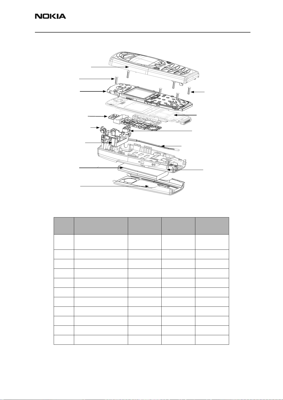
Exploded View
A-cover Assy
Screws
UI Assy
Shield Cans
Power Button
PIFA Assy
Battery
B-cover
Assembly Parts List
Qty Description
Product code
RH-3
Whip Antenna Assy
Product code
RH-3P
Screws
PWB Board
Headset Jack
D-cove
Product code
RH-3DNG
1A-cover assembly
9497267 9497267 9497267
(includes keymat)
6 screws 6290159 6290159 6290159
1 UI assembly 9491486 9481010 9481010
1 PWB module 0202057 0202081 0202107
1 headset jack 5400293 5400293 5400293
1 power button 9452765 9452765 9452765
1 PIFA assembly 0660287 0660287 0660287
1 whip antenna assembly 0660288 0660288 0660288
1 D-cover 9452762 9452762 9452762
1 battery 0670398 0670398 0670398
1 B-cover 9497265 9497265 9497265
Issue 1 06/2003 Nokia Corporation Confidential Page 5
Page 17
RH-3
Parts Lists CCS Technical Documentation
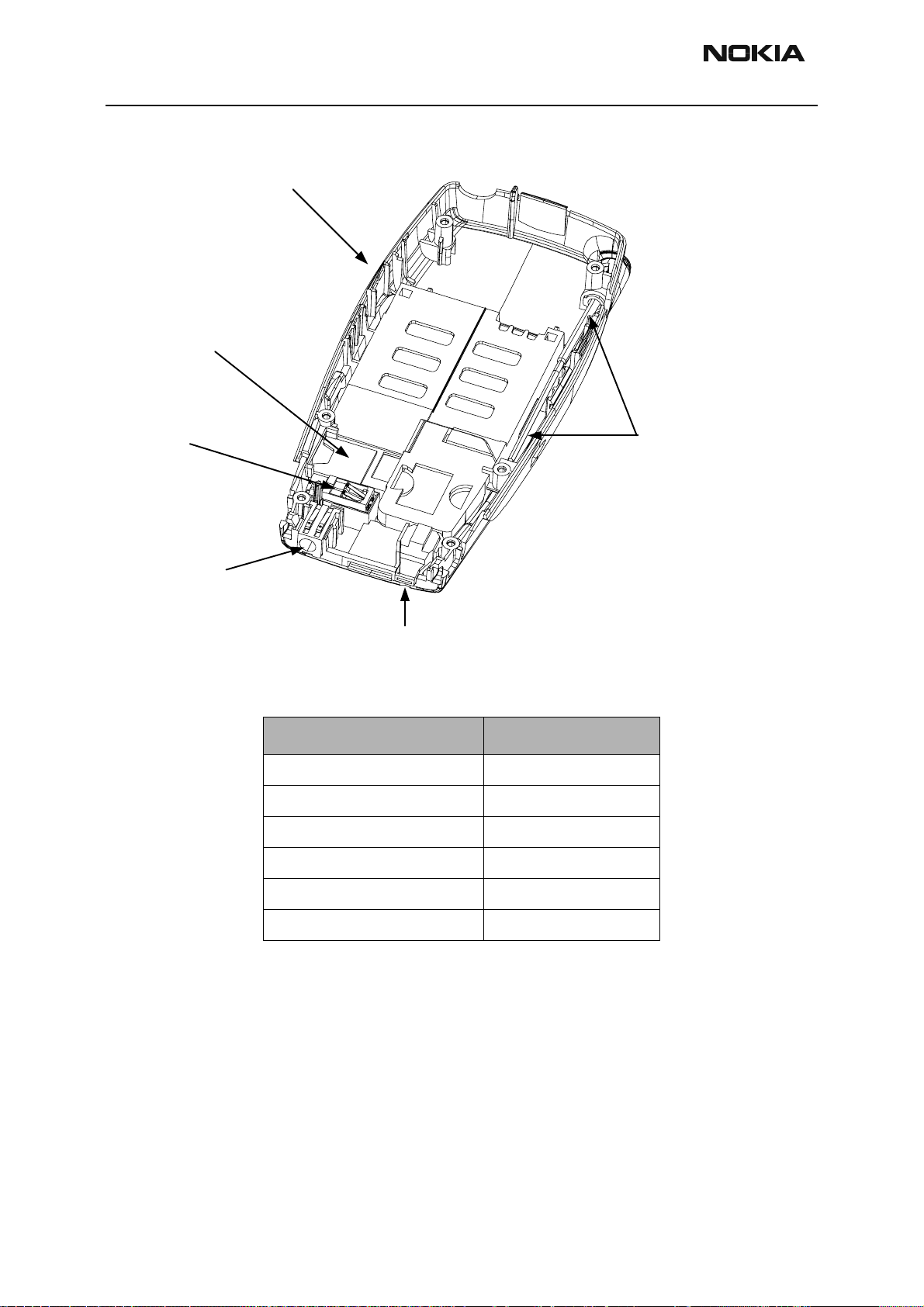
D-cover Assembly
D-Cover
Buzzer
Gasket
Vibra
DC Jack
D-cover Assembly Parts List
Description Product Code
D-cover 9452762
buzzer gasket 9481009
vibra 6800063
DC jack 5400243
Whip Antenna
Assembly
Microphone
microphone 5140265
whip antenna assembly 0660288
Page 6 Nokia Corporation Confidential Issue 1 06/2003
Page 18
RH-3
CCS Technical Documentation Parts Lists
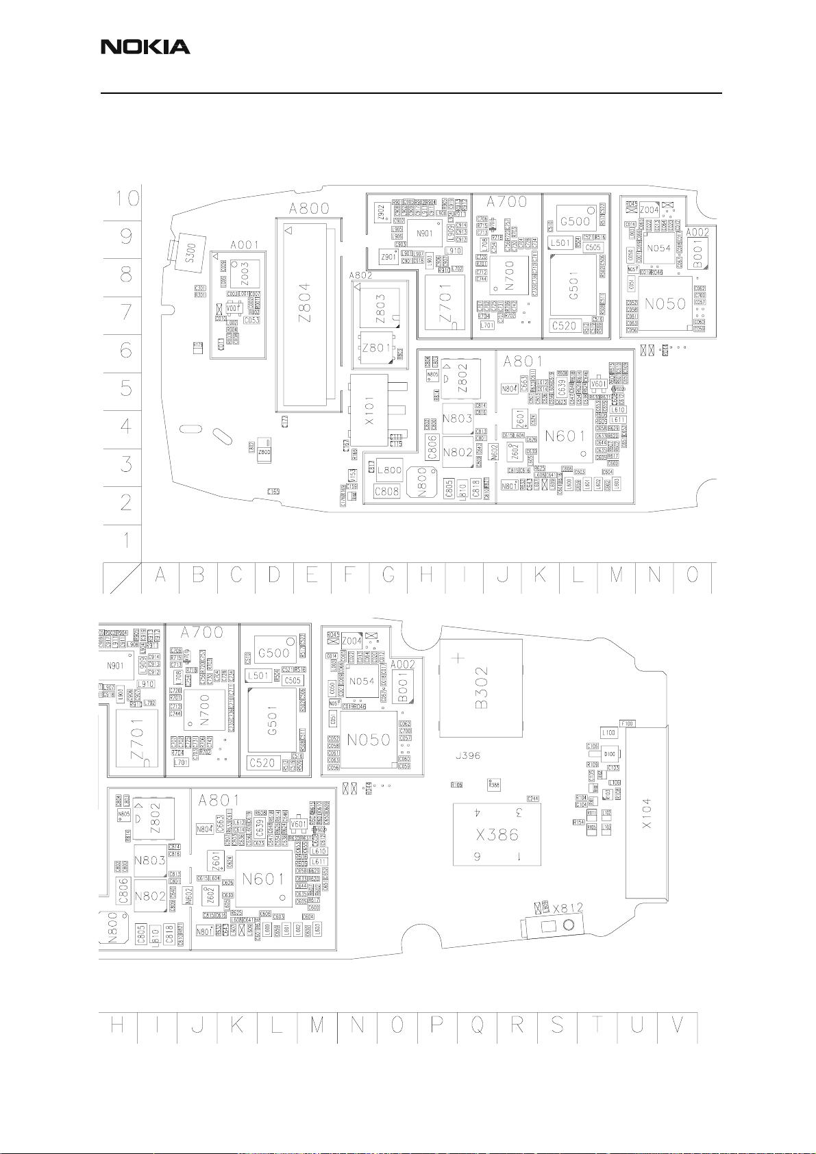
Model 2285
Component Layout - Top
Issue 1 06/2003 Nokia Corporation Confidential Page 7
Page 19
RH-3
Parts Lists CCS Technical Documentation
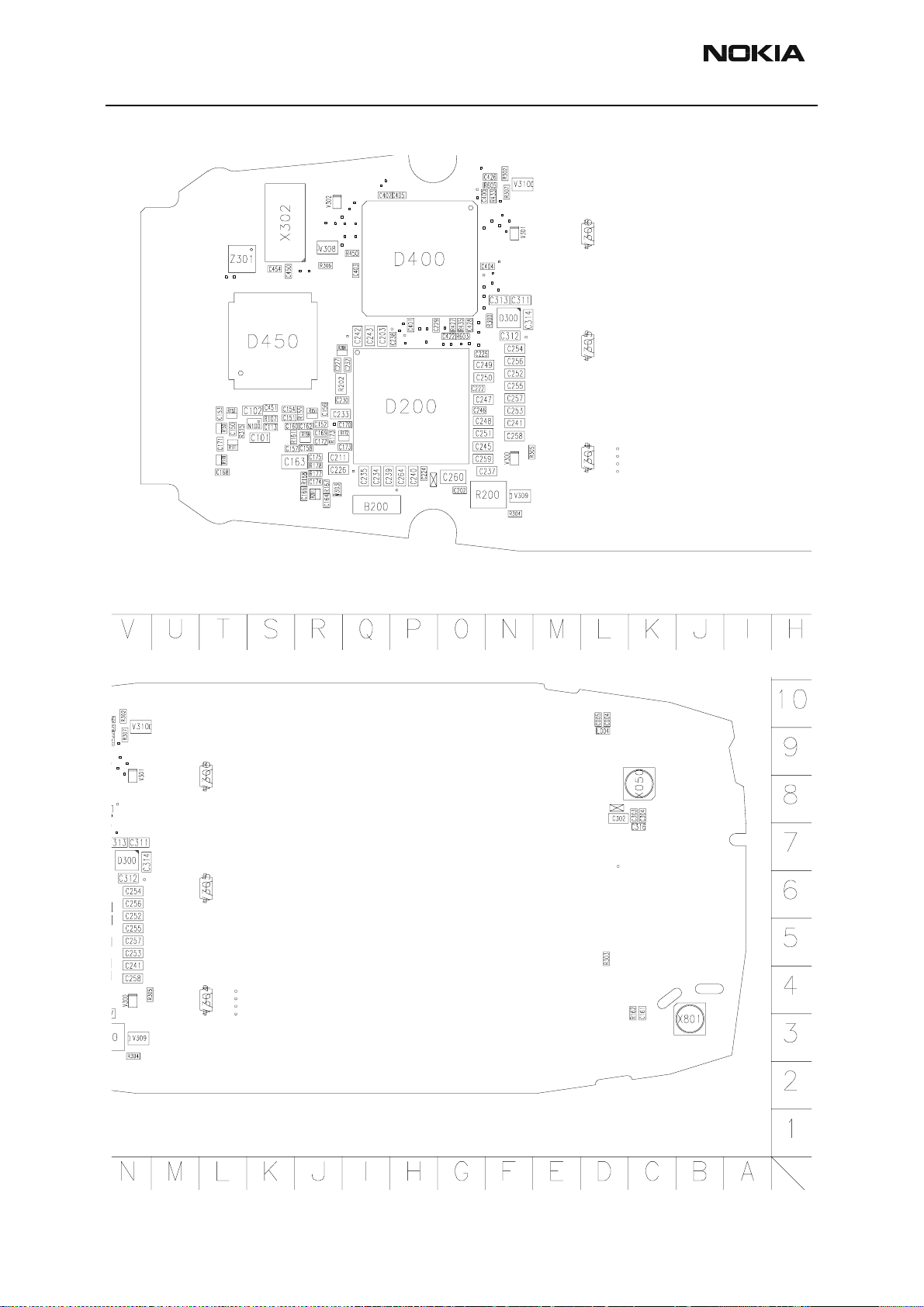
Component Layout - Bottom
Page 8 Nokia Corporation Confidential Issue 1 06/2003
Page 20
RH-3
CCS Technical Documentation Parts Lists
RH-3 (2285) — EDMS Issue 2.59 Code: 0202057
Item Code Side X Y Description Value Type
R001 1430788 Top D 7 chip res 0W06 22K J 0402
R002 1430728 Top C 7 chip res 0W06 120R J 0402
R003 1430700 Top C 6 chip res 0W06 10R J 0402
R004 1430732 Top C 7 chip res 0W06 180R J 0402
R044 1430804 Top N 6 chip res 0W06 100K J 0402
R045 1430690 Top M 10 chip res jumper 0R0 0402
R046 1430804 Top N 8 chip res 0W06 100K J 0402
R100 1620027 Top T 6 res network 0W06 2X47R J 0404
R101 1620027 Top T 6 res network 0W06 2X47R J 0404
R102 1620027 Top T 6 res network 0W06 2X47R J 0404
R103 4120011 Top T 6 ZDIX4 IP4043CX5 CA 14V2 10W CSP5
R104 1430812 Top T 6 chip res 0W06 220K J 0402
R105 1825031 Top T 5 varistor array 2XVWM 16V VC50 0405
R106 1820039 Top P 6 NTC res 0W1 47K J B=4050+/-3% 0402
R107 1430804 Bottom S 5 chip res 0W06 100K J 0402
R108 1430690 Top U 6 chip res jumper 0R0 0402
R109 1430804 Top T 7 chip res 0W06 100K J 0402
R111 1825031 Top T 5 varistor array 2XVWM 16V VC50 0405
R150 1620031 Bottom T 4 res network 0W06 2X1K0 J 0404
R151 1620031 Bottom R 5 res network 0W06 2X1K0 J 0404
R152 1620031 Bottom T 5 res network 0W06 2X1K0 J 0404
R154 1430726 Top T 5 chip res 0W06 100R J 0402
R155 1430796 Bottom R 5 chip res 0W06 47K J 0402
R159 1620031 Bottom R 4 res network 0W06 2X1K0 J 0404
R160 1620031 Top F 2 res network 0W06 2X1K0 J 0404
R161 1430796 Bottom S 4 chip res 0W06 47K J 0402
R162 1430754 Bottom C 4 chip res 0W06 1K0 J 0402
R166 1430700 Top F 3 chip res 0W06 10R J 0402
R167 1430693 Bottom R 3 chip res 0W06 5R6 J 0402
R168 1430693 Bottom R 3 chip res 0W06 5R6 J 0402
R169 1430758 Top F 2 chip res 0W06 1K5 J 0402
Issue 1 06/2003 Nokia Corporation Confidential Page 9
Page 21

RH-3
Parts Lists CCS Technical Documentation
Item Code Side X Y Description Value Type
R170 1620031 Bottom T 4 res network 0W06 2X1K0 J 0404
R171 1620031 Bottom T 4 res network 0W06 2X1K0 J 0404
R172 1620031 Bottom Q 4 res network 0W06 2X1K0 J 0404
R173 1430796 Bottom R 4 chip res 0W06 47K J 0402
R177 1430693 Bottom R 3 chip res 0W06 5R6 J 0402
R178 1430693 Bottom R 4 chip res 0W06 5R6 J 0402
R179 1825031 Top B 6 varistor array 2XVWM 16V VC50 0405
R200 1419003 Bottom N 3 chip res 0W5 0R22 J 200ppm 1210
R201 1620035 Bottom R 3 res network 0W06 2X10R J 0404
R202 1620067 Bottom R 5 res network 0W06 4X100K J 0804
R208 1620029 Bottom R 6 res network 0W06 2X4K7 J 0404
R300 1430728 Bottom N 7 chip res 0W06 120R J 0402
R301 1430770 Top B 8 chip res 0W06 4K7 J 0402
R302 1430754 Bottom N 10 chip res 0W06 1K0 J 0402
R303 1430778 Bottom D 5 chip res 0W06 10K J 0402
R304 1430728 Bottom N 3 chip res 0W06 120R J 0402
R305 1430728 Bottom N 4 chip res 0W06 120R J 0402
R306 1430728 Bottom R 8 chip res 0W06 120R J 0402
R307 1430728 Bottom N 9 chip res 0W06 120R J 0402
R315 1430804 Bottom T 4 chip res 0W06 100K J 0402
R388 4120071 Top Q 6 ASIP EMIF03-SIM01 SIM filter BGA8
R427 1430764 Bottom O 7 chip res 0W06 3K3 J 0402
R433 1430764 Bottom N 9 chip res 0W06 3K3 J 0402
R435 1430764 Bottom O 7 chip res 0W06 3K3 J 0402
R450 1430770 Bottom Q 8 chip res 0W06 4K7 J 0402
R502 1430681 Top M 8 chip res 0W06 4R3 J 0402
R504 1430718 Top L 9 chip res 0W06 47R J 0402
R508 1430770 Top M 7 chip res 0W06 4K7 J 0402
R509 1430770 Top M 7 chip res 0W06 4K7 J 0402
R512 1430772 Top L 7 chip res 0W06 5K6 J 0402
R516 1430700 Top M 9 chip res 0W06 10R J 0402
R517 1430778 Top M 10 chip res 0W06 10K J 0402
Page 10 Nokia Corporation Confidential Issue 1 06/2003
Page 22

RH-3
CCS Technical Documentation Parts Lists
Item Code Side X Y Description Value Type
R601 1430754 Top M 5 chip res 0W06 1K0 J 0402
R602 1430726 Top M 4 chip res 0W06 100R J 0402
R603 1430726 Bottom O 6 chip res 0W06 100R J 0402
R604 1430754 Top M 5 chip res 0W06 1K0 J 0402
R605 1430726 Bottom N 9 chip res 0W06 100R J 0402
R606 1430693 Top M 4 chip res 0W06 5R6 J 0402
R607 1430681 Top M 4 chip res 0W06 4R3 J 0402
R608 1430681 Top L 5 chip res 0W06 4R3 J 0402
R609 1430693 Top M 4 chip res 0W06 5R6 J 0402
R614 1430700 Top L 5 chip res 0W06 10R J 0402
R615 1430754 Top M 6 chip res 0W06 1K0 J 0402
R616 1430758 Top L 3 chip res 0W06 1K5 J 0402
R617 1430681 Top M 3 chip res 0W06 4R3 J 0402
R618 1430700 Top L 5 chip res 0W06 10R J 0402
R620 1430700 Top M 4 chip res 0W06 10R J 0402
R624 1430762 Top L 5 chip res 0W06 2K2 J 0402
R625 1430756 Top K 3 chip res 0W06 1K2 J 0402
R626 1430772 Top L 5 chip res 0W06 5K6 J 0402
R629 1430693 Top M 4 chip res 0W06 5R6 J 0402
R630 1430772 Top L 5 chip res 0W06 5K6 J 0402
R631 1430772 Top M 5 chip res 0W06 5K6 J 0402
R632 1430691 Top K 3 chip res 0W06 2R2 J 0402
R633 1430681 Top K 5 chip res 0W06 4R3 J 0402
R701 1430700 Top I 8 chip res 0W06 10R J 0402
R702 1430754 Top J 7 chip res 0W06 1K0 J 0402
R703 1430700 Top J 9 chip res 0W06 10R J 0402
R704 1430746 Top J 7 chip res 0W06 560R J 0402
R706 1430806 Top J 7 chip res 0W06 120K J 0402
R715 1430700 Top I 9 chip res 0W06 10R J 0402
R718 1430772 Top J 9 chip res 0W06 5K6 J 0402
R720 1430764 Top J 9 chip res 0W06 3K3 J 0402
R803 1430754 Top G 6 chip res 0W06 1K0 J 0402
Issue 1 06/2003 Nokia Corporation Confidential Page 11
Page 23

RH-3
Parts Lists CCS Technical Documentation
Item Code Side X Y Description Value Type
R814 1430754 Top H 5 chip res 0W06 1K0 J 0402
R821 1820039 Top J 3 NTC res 0W1 47K J B=4050+/-3% 0402
R901 1430681 Top G 10 chip res 0W06 4R3 J 0402
R902 1430796 Top H 10 chip res 0W06 47K J 0402
R904 1430796 Top H 10 chip res 0W06 47K J 0402
R905 1430724 Top H 10 chip res 0W06 82R J 0402
R910 1430693 Top H 8 chip res 0W06 5R6 J 0402
R911 1430708 Top I 10 chip res 0W06 18R J 0402
R912 1430738 Top I 10 chip res 0W06 270R J 0402
R913 1430738 Top I 10 chip res 0W06 270R J 0402
C001 2320544 Top N 9 chip cap NP0 22P J 50V 0402
C002 2320805 Top C 7 chip cap X5R 100N K 10V 0402
C003 2320544 Top C 8 chip cap NP0 22P J 50V 0402
C004 2320540 Bottom D 10 chip cap NP0 15P J 50V 0402
C005 2320903 Bottom D 10 chip cap NP0 HQ 2P7 J 16V 0402
C007 2320544 Top C 8 chip cap NP0 22P J 50V 0402
C008 2320544 Top C 6 chip cap NP0 22P J 50V 0402
C009 2320544 Top C 8 chip cap NP0 22P J 50V 0402
C010 2320903 Top C 7 chip cap NP0 HQ 2P7 J 16V 0402
C011 2320544 Top C 6 chip cap NP0 22P J 50V 0402
C012 2320778 Top O 9 chip cap X7R 10N K 16V 0402
C013 2320778 Top N 9 chip cap X7R 10N K 16V 0402
C014 2320524 Top M 9 chip cap NP0 3P3 C 50V 0402
C017 2320805 Top O 9 chip cap X5R 100N K 10V 0402
C018 2320903 Top O 9 chip cap NP0 HQ 2P7 J 16V 0402
C019 2320805 Top N 8 chip cap X5R 100N K 10V 0402
C020 2320805 Top N 9 chip cap X5R 100N K 10V 0402
C022 2320544 Top N 9 chip cap NP0 22P J 50V 0402
C050 2320481 Top M 9 chip cap X5R 1U K 6V3 0603
C051 2320481 Top M 8 chip cap X5R 1U K 6V3 0603
C052 2320778 Top M 7 chip cap X7R 10N K 16V 0402
C053 2320481 Top C 7 chip cap X5R 1U K 6V3 0603
Page 12 Nokia Corporation Confidential Issue 1 06/2003
Page 24
RH-3
CCS Technical Documentation Parts Lists
Item Code Side X Y Description Value Type
C056 2320805 Top M 7 chip cap X5R 100N K 10V 0402
C057 2320805 Top O 7 chip cap X5R 100N K 10V 0402
C058 2320805 Top M 7 chip cap X5R 100N K 10V 0402
C059 2320805 Top O 7 chip cap X5R 100N K 10V 0402
C060 2320805 Top O 7 chip cap X5R 100N K 10V 0402
C061 2320805 Top M 7 chip cap X5R 100N K 10V 0402
C062 2320805 Top O 8 chip cap X5R 100N K 10V 0402
C063 2320805 Top M 7 chip cap X5R 100N K 10V 0402
C064 2320544 Top N 9 chip cap NP0 22P J 50V 0402
C065 2320544 Top N 9 chip cap NP0 22P J 50V 0402
C066 2320544 Top N 9 chip cap NP0 22P J 50V 0402
C067 2320544 Top O 8 chip cap NP0 22P J 50V 0402
C069 2320544 Top N 9 chip cap NP0 22P J 50V 0402
C101 2320481 Bottom S 4 chip cap X5R 1U K 6V3 0603
C102 2320481 Bottom S 5 chip cap X5R 1U K 6V3 0603
C103 2320544 Top T 7 chip cap NP0 22P J 50V 0402
C104 2320544 Top T 6 chip cap NP0 22P J 50V 0402
C105 2320544 Top T 6 chip cap NP0 22P J 50V 0402
C106 2320584 Top T 7 chip cap X7R 1N0 J 50V 0402
C111 2320560 Top G 4 chip cap NP0 100P J 50V 0402
C113 2320778 Bottom S 4 chip cap X7R 10N K 16V 0402
C115 2320785 Top G 4 chip cap X7R 47N K 10V 0402
C150 2320805 Bottom T 4 chip cap X5R 100N K 10V 0402
C151 2320805 Bottom S 5 chip cap X5R 100N K 10V 0402
C152 2320552 Bottom R 4 chip cap NP0 47P J 50V 0402
C153 2320552 Bottom T 5 chip cap NP0 47P J 50V 0402
C154 2320805 Bottom S 5 chip cap X5R 100N K 10V 0402
C156 2320552 Bottom R 5 chip cap NP0 47P J 50V 0402
C157 2320805 Bottom S 4 chip cap X5R 100N K 10V 0402
C158 2320552 Bottom R 4 chip cap NP0 47P J 50V 0402
C159 2320552 Top F 3 chip cap NP0 47P J 50V 0402
C160 2320805 Bottom S 4 chip cap X5R 100N K 10V 0402
Issue 1 06/2003 Nokia Corporation Confidential Page 13
Page 25

RH-3
Parts Lists CCS Technical Documentation
Item Code Side X Y Description Value Type
C161 2320805 Bottom C 4 chip cap X5R 100N K 10V 0402
C162 2320552 Bottom R 4 chip cap NP0 47P J 50V 0402
C163 2310037 Bottom S 4 chip cap X5R 10U M 6V3 0805
C164 2320552 Bottom R 3 chip cap NP0 47P J 50V 0402
C165 2320552 Top D 2 chip cap NP0 47P J 50V 0402
C166 2320552 Bottom R 3 chip cap NP0 47P J 50V 0402
C167 2320552 Top F 4 chip cap NP0 47P J 50V 0402
C168 2320805 Bottom T 3 chip cap X5R 100N K 10V 0402
C169 2320805 Bottom R 4 chip cap X5R 100N K 10V 0402
C170 2320552 Bottom Q 4 chip cap NP0 47P J 50V 0402
C171 2320552 Bottom T 4 chip cap NP0 47P J 50V 0402
C172 2320805 Bottom R 4 chip cap X5R 100N K 10V 0402
C173 2320552 Bottom Q 4 chip cap NP0 47P J 50V 0402
C174 2320552 Bottom R 3 chip cap NP0 47P J 50V 0402
C175 2320552 Bottom R 4 chip cap NP0 47P J 50V 0402
C176 2320805 Top F 2 chip cap X5R 100N K 10V 0402
C177 2320552 Top D 4 chip cap NP0 47P J 50V 0402
C202 2320778 Bottom O 3 chip cap X7R 10N K 16V 0402
C203 2320481 Bottom Q 6 chip cap X5R 1U K 6V3 0603
C211 2320481 Bottom R 4 chip cap X5R 1U K 6V3 0603
C222 2320805 Bottom O 5 chip cap X5R 100N K 10V 0402
C224 2320143 Bottom P 3 chip cap X5R 220N K 6.3V 0402
C225 2320805 Bottom O 6 chip cap X5R 100N K 10V 0402
C226 2320481 Bottom R 4 chip cap X5R 1U K 6V3 0603
C227 2320778 Bottom R 6 chip cap X7R 10N K 16V 0402
C229 2320805 Bottom P 7 chip cap X5R 100N K 10V 0402
C230 2320778 Bottom R 5 chip cap X7R 10N K 16V 0402
C232 2320778 Bottom Q 6 chip cap X7R 10N K 16V 0402
C233 2320481 Bottom R 5 chip cap X5R 1U K 6V3 0603
C234 2320481 Bottom Q 3 chip cap X5R 1U K 6V3 0603
C235 2320481 Bottom Q 3 chip cap X5R 1U K 6V3 0603
C237 2320481 Bottom N 3 chip cap X5R 1U K 6V3 0603
Page 14 Nokia Corporation Confidential Issue 1 06/2003
Page 26

RH-3
CCS Technical Documentation Parts Lists
Item Code Side X Y Description Value Type
C238 2320805 Bottom P 6 chip cap X5R 100N K 10V 0402
C239 2320481 Bottom Q 3 chip cap X5R 1U K 6V3 0603
C240 2320481 Bottom P 3 chip cap X5R 1U K 6V3 0603
C241 2320481 Bottom N 5 chip cap X5R 1U K 6V3 0603
C242 2320481 Bottom Q 6 chip cap X5R 1U K 6V3 0603
C243 2320481 Bottom Q 6 chip cap X5R 1U K 6V3 0603
C244 2320805 Top R 6 chip cap X5R 100N K 10V 0402
C245 2320481 Bottom O 4 chip cap X5R 1U K 6V3 0603
C246 2320805 Bottom O 5 chip cap X5R 100N K 10V 0402
C247 2320481 Bottom O 5 chip cap X5R 1U K 6V3 0603
C248 2320481 Bottom O 5 chip cap X5R 1U K 6V3 0603
C249 2320481 Bottom O 6 chip cap X5R 1U K 6V3 0603
C250 2320481 Bottom O 5 chip cap X5R 1U K 6V3 0603
C251 2320481 Bottom O 4 chip cap X5R 1U K 6V3 0603
C252 2320481 Bottom N 6 chip cap X5R 1U K 6V3 0603
C253 2320481 Bottom N 5 chip cap X5R 1U K 6V3 0603
C254 2320481 Bottom N 6 chip cap X5R 1U K 6V3 0603
C255 2320481 Bottom N 5 chip cap X5R 1U K 6V3 0603
C256 2320481 Bottom N 6 chip cap X5R 1U K 6V3 0603
C257 2320481 Bottom N 5 chip cap X5R 1U K 6V3 0603
C258 2320481 Bottom N 4 chip cap X5R 1U K 6V3 0603
C259 2320481 Bottom O 4 chip cap X5R 1U K 6V3 0603
C260 2310037 Bottom O 3 chip cap X5R 10U M 6V3 0805
C264 2320481 Bottom P 3 chip cap X5R 1U K 6V3 0603
C301 2320778 Top B 8 chip cap X7R 10N K 16V 0402
C302 2320125 Bottom D 8 chip cap X5R 1U K16V 0603
C303 2320805 Bottom C 8 chip cap X5R 100N K 10V 0402
C304 2320805 Bottom C 8 chip cap X5R 100N K 10V 0402
C311 2320125 Bottom N 7 chip cap X5R 1U K16V 0603
C312 2320125 Bottom N 6 chip cap X5R 1U K16V 0603
C313 2320125 Bottom N 7 chip cap X5R 1U K16V 0603
C314 2320125 Bottom N 7 chip cap X5R 1U K16V 0603
Issue 1 06/2003 Nokia Corporation Confidential Page 15
Page 27
RH-3
Parts Lists CCS Technical Documentation
Item Code Side X Y Description Value Type
C316 2320805 Bottom C 7 chip cap X5R 100N K 10V 0402
C400 2320805 Bottom O 9 chip cap X5R 100N K 10V 0402
C401 2320805 Bottom P 7 chip cap X5R 100N K 10V 0402
C402 2320805 Bottom Q 9 chip cap X5R 100N K 10V 0402
C403 2320805 Bottom Q 8 chip cap X5R 100N K 10V 0402
C404 2320805 Bottom N 8 chip cap X5R 100N K 10V 0402
C405 2320805 Bottom P 9 chip cap X5R 100N K 10V 0402
C422 2320778 Bottom O 6 chip cap X7R 10N K 16V 0402
C426 2320778 Bottom N 10 chip cap X7R 10N K 16V 0402
C428 2320778 Bottom O 7 chip cap X7R 10N K 16V 0402
C450 2320778 Bottom S 8 chip cap X7R 10N K 16V 0402
C451 2320805 Bottom S 5 chip cap X5R 100N K 10V 0402
C454 2320778 Bottom S 8 chip cap X7R 10N K 16V 0402
C505 2312243 Top L 9 chip cap X5R 4U7 K 6V3 0805
C506 2320548 Top M 8 chip cap NP0 33P J 50V 0402
C510 2320584 Top K 9 chip cap X7R 1N0 J 50V 0402
C511 2320584 Top M 7 chip cap X7R 1N0 J 50V 0402
C516 2320588 Top M 7 chip cap X7R 1N5 J 50V 0402
C519 2320618 Top L 7 chip cap X7R 4N7 J 25V 0402
C520 2420029 Top L 7 chip cap PPS 39N G 16V 1206
C521 2320805 Top L 9 chip cap X5R 100N K 10V 0402
C522 2320584 Top M 10 chip cap X7R 1N0 J 50V 0402
C600 2320584 Top M 3 chip cap X7R 1N0 J 50V 0402
C601 2320596 Top L 2 chip cap X7R 3N3 J 50V 0402
C602 2320548 Top M 3 chip cap NP0 33P J 50V 0402
C603 2320540 Top L 3 chip cap NP0 15P J 50V 0402
C604 2320009 Top M 3 chip cap NP0 10P J 50V 0402
C605 2320584 Top M 3 chip cap X7R 1N0 J 50V 0402
C606 2320584 Top L 3 chip cap X7R 1N0 J 50V 0402
C608 2320637 Top M 5 chip cap NP0 6P0 +/-0.5P
50V
C609 2320805 Top M 6 chip cap X5R 100N K 10V 0402
C610 2320805 Top M 6 chip cap X5R 100N K 10V 0402
0402
Page 16 Nokia Corporation Confidential Issue 1 06/2003
Page 28

RH-3
CCS Technical Documentation Parts Lists
Item Code Side X Y Description Value Type
C611 2320584 Top K 5 chip cap X7R 1N0 J 50V 0402
C612 2320637 Top M 5 chip cap NP0 6P0 +/-0.5P
50V
C614 2320520 Top K 5 chip cap NP0 2P2 C 50V 0402
C615 2320544 Top J 4 chip cap NP0 22P J 50V 0402
C616 2320778 Top K 3 chip cap X7R 10N K 16V 0402
C619 2320516 Top K 5 chip cap NP0 1P5 C 50V 0402
C623 2320520 Top L 5 chip cap NP0 2P2 C 50V 0402
C624 2320550 Top K 4 chip cap NP0 39P J 50V 0402
C626 2320584 Top K 4 chip cap X7R 1N0 J 50V 0402
C630 2320544 Top K 3 chip cap NP0 22P J 50V 0402
C633 2320584 Top M 4 chip cap X7R 1N0 J 50V 0402
C635 2320584 Top M 3 chip cap X7R 1N0 J 50V 0402
C636 2320805 Top K 5 chip cap X5R 100N K 10V 0402
C638 2320584 Top L 5 chip cap X7R 1N0 J 50V 0402
C639 2312243 Top L 5 chip cap X5R 4U7 K 6V3 0805
0402
C640 2320544 Top I 3 chip cap NP0 22P J 50V 0402
C641 2320501 Top K 3 chip cap NP0 1P2 B 50V 0402
C643 2320584 Top K 3 chip cap X7R 1N0 J 50V 0402
C644 2320560 Top M 4 chip cap NP0 100P J 50V 0402
C646 2320592 Top L 5 chip cap X7R 2N2 J 50V 0402
C647 2320592 Top L 5 chip cap X7R 2N2 J 50V 0402
C648 2320771 Top L 5 chip cap X5R 27N K 10V 0402
C650 2320778 Top M 5 chip cap X7R 10N K 16V 0402
C651 2320805 Top M 4 chip cap X5R 100N K 10V 0402
C652 2320778 Top M 4 chip cap X7R 10N K 16V 0402
C653 2320538 Top M 5 chip cap NP0 12P J 50V 0402
C654 2320805 Top L 5 chip cap X5R 100N K 10V 0402
C655 2320538 Top M 5 chip cap NP0 12P J 50V 0402
C656 2320552 Top K 5 chip cap NP0 47P J 50V 0402
C658 2320584 Top M 4 chip cap X7R 1N0 J 50V 0402
C659 2320560 Top L 3 chip cap NP0 100P J 50V 0402
C663 2320481 Top K 5 chip cap X5R 1U K 6V3 0603
Issue 1 06/2003 Nokia Corporation Confidential Page 17
Page 29
RH-3
Parts Lists CCS Technical Documentation
Item Code Side X Y Description Value Type
C700 2320538 Top O 8 chip cap NP0 12P J 50V 0402
C702 2320552 Top J 7 chip cap NP0 47P J 50V 0402
C703 2320778 Top J 7 chip cap X7R 10N K 16V 0402
C704 2320778 Top J 9 chip cap X7R 10N K 16V 0402
C706 2320584 Top I 10 chip cap X7R 1N0 J 50V 0402
C707 2320552 Top I 7 chip cap NP0 47P J 50V 0402
C710 2320805 Top K 8 chip cap X5R 100N K 10V 0402
C711 2320538 Top K 9 chip cap NP0 12P J 50V 0402
C712 2320584 Top I 8 chip cap X7R 1N0 J 50V 0402
C713 2320620 Top I 9 chip cap X7R 10N J 16V 0402
C720 2320805 Top I 9 chip cap X5R 100N K 10V 0402
C725 2320805 Top J 7 chip cap X5R 100N K 10V 0402
C728 2320760 Top K 9 chip cap X7R 4N7 K 25V 0402
C730 2320805 Top J 9 chip cap X5R 100N K 10V 0402
C731 2320805 Top J 7 chip cap X5R 100N K 10V 0402
C734 2320805 Top K 9 chip cap X5R 100N K 10V 0402
C735 2320584 Top K 8 chip cap X7R 1N0 J 50V 0402
C736 2320584 Top K 8 chip cap X7R 1N0 J 50V 0402
C742 2320805 Top J 7 chip cap X5R 100N K 10V 0402
C744 2320620 Top I 8 chip cap X7R 10N J 16V 0402
C754 2320009 Top J 9 chip cap NP0 10P J 50V 0402
C756 2320787 Top J 9 chip cap X7R 15N K 16V 0402
C757 2320805 Top J 9 chip cap X5R 100N K 10V 0402
C800 2320584 Top H 4 chip cap X7R 1N0 J 50V 0402
C801 2320732 Top I 4 chip cap X7R 330P K 50V 0402
C802 2320564 Top H 4 chip cap NP0 150P J 50V 0402
C803 2320805 Top K 5 chip cap X5R 100N K 10V 0402
C804 2320604 Top H 6 chip cap NP0 18P J 50V 0402
C805 2310037 Top I 2 chip cap X5R 10U M 6V3 0805
C806 2312255 Top H 4 chip cap X5R 10U K 10V 1206
C807 2320783 Top K 5 chip cap X7R 33N K 10V 0402
C808 2312255 Top G 2 chip cap X5R 10U K 10V 1206
Page 18 Nokia Corporation Confidential Issue 1 06/2003
Page 30

RH-3
CCS Technical Documentation Parts Lists
Item Code Side X Y Description Value Type
C809 2320778 Top I 3 chip cap X7R 10N K 16V 0402
C810 2320778 Top J 2 chip cap X7R 10N K 16V 0402
C813 2320568 Top I 4 chip cap X7R 220P J 50V 0402
C814 2320584 Top I 5 chip cap X7R 1N0 J 50V 0402
C815 2320584 Top J 3 chip cap X7R 1N0 J 50V 0402
C816 2320778 Top I 4 chip cap X7R 10N K 16V 0402
C817 2320560 Top G 3 chip cap NP0 100P J 50V 0402
C818 2310037 Top I 2 chip cap X5R 10U M 6V3 0805
C901 2320554 Top G 8 chip cap NP0 56P J 50V 0402
C902 2320508 Top G 10 chip cap NP0 1P0 C 50V 0402
C903 2320520 Top G 9 chip cap NP0 2P2 C 50V 0402
C905 2320805 Top H 10 chip cap X5R 100N K 10V 0402
C906 2320560 Top H 8 chip cap NP0 100P J 50V 0402
C907 2320524 Top I 8 chip cap NP0 3P3 C 50V 0402
C908 2320546 Top G 10 chip cap NP0 27P J 50V 0402
C909 2320560 Top H 10 chip cap NP0 100P J 50V 0402
C911 2320560 Top H 10 chip cap NP0 100P J 50V 0402
C912 2320520 Top I 9 chip cap NP0 2P2 C 50V 0402
C913 2320596 Top I 9 chip cap X7R 3N3 J 50V 0402
C914 2320805 Top I 9 chip cap X5R 100N K 10V 0402
C917 2320546 Top H 10 chip cap NP0 27P J 50V 0402
C918 2320785 Top H 8 chip cap X7R 47N K 10V 0402
C919 2320584 Top I 10 chip cap X7R 1N0 J 50V 0402
L001 3646065 Top C 8 chip coil 12N J Q31/800MHz 0402
L002 3646053 Top C 7 chip coil 4N7+/-0N3 Q28/800M 0402
L003 3646091 Top M 9 chip coil 6N8 J Q27/800MHz 0402
L004 3646065 Bottom D 9 chip coil 12N J Q31/800MHz 0402
L005 3646021 Top C 8 chip coil 22N J Q7/100MHz 0402
L100 3203743 Top T 7 ferrite bead 0R03 42R/100M 3A 0805
L102 3203801 Top T 5 chip bead array 2X1000R 0405
L103 3203801 Top T 5 chip bead array 2X1000R 0405
L106 3203725 Top T 6 ferrite bead 600R/100MHz 0805
Issue 1 06/2003 Nokia Corporation Confidential Page 19
Page 31

RH-3
Parts Lists CCS Technical Documentation
Item Code Side X Y Description Value Type
L501 4550257 Top L 9 dir coupler 1066+/- 14MHz 3.2x1.6
L600 3645305 Top L 3 chip coil 12N G Q35/250MHz 0603
L601 3645305 Top L 3 chip coil 12N G Q35/250MHz 0603
L602 3645305 Top M 3 chip coil 12N G Q35/250MHz 0603
L603 3645305 Top M 3 chip coil 12N G Q35/250MHz 0603
L604 3646009 Top J 4 chip coil 10N J Q30/800MHz 0402
L605 3646009 Top K 3 chip coil 10N J Q30/800MHz 0402
L606 3646047 Top K 5 chip coil 3N3+/-0N3 Q28/800M 0402
L607 3646047 Top K 3 chip coil 3N3+/-0N3 Q28/800M 0402
L608 3646059 Top K 3 chip coil 5N6+/-0N3 Q28/800M 0402
L609 3646047 Top K 3 chip coil 3N3+/-0N3 Q28/800M 0402
L610 3645187 Top M 5 chip coil 6N8 J Q10/100MHz 0603
L611 3645187 Top M 4 chip coil 6N8 J Q10/100MHz 0603
L612 3646099 Top K 5 chip coil 2N7+/-0N3 Q29/800M 0402
L701 3645243 Top J 7 chip coil 47N G Q38/200MHz 0603
L702 3646027 Top I 8 chip coil 33N J Q7/100MHz 0402
L708 3645213 Top J 9 chip coil 22N J Q38/250MHz 0603
L800 3640133 Top G 3 chip coil 2U7 K Q21/1MHz 3.0X3.4
L802 3646081 Top C 4 chip coil 68N J Q17/300MHz 0402
L803 3646009 Top H 6 chip coil 10N J Q30/800MHz 0402
L809 3646033 Top S 3 chip coil 1N0+/-0N3 Q8/100M 0402
L810 3203705 Top I 2 ferrite bead 0.015R 42R/100M 0805
L901 3646065 Top G 9 chip coil 12N J Q31/800MHz 0402
L902 3646099 Top G 10 chip coil 2N7+/-0N3 Q29/800M 0402
L903 3645161 Top H 8 chip coil 150N J Q14/100MHz 0603
L904 3646053 Top I 10 chip coil 4N +/-0N3 Q28/800M 0402
L905 3646405 Top G 9 chip coil 6N2 J Q20/250MHz 0402
L906 3646415 Top G 9 chip coil 19N J Q24/250MHz 0402
L907 3646061 Top H 9 chip coil 15N J Q30/800MHz 0402
L908 3646061 Top H 10 chip coil 15N J Q30/800MHz 0402
L909 3645161 Top I 9 chip coil 150N J Q14/100MHz 0603
L910 3645011 Top I 9 chip coil 68NH J Q12/100MHz 0603
Page 20 Nokia Corporation Confidential Issue 1 06/2003
Page 32

RH-3
CCS Technical Documentation Parts Lists
Item Code Side X Y Description Value Type
L911 3646065 Top H 10 chip coil 12N J Q31/800MHz 0402
V001 4210189 Top C 7 TR BFP620 N2.5V70GHz F=0.7 SOT343
V153 4120061 Top F 3 ASIP 2 lines EMI/ESD filter BGA6
V300 4860339 Bottom N 4 LED LWL88S
V301 4860339 Bottom N 8 LED LWL88S
V302 4860339 Bottom R 9 LED LWL88S
V303 4860339 Bottom R 3 LED LWL88S
V304 4860317 Bottom L 4 LED LWY87C White 140 MCD@20MA 120’
V305 4860317 Bottom L 6 LED LWY87C White 140 MCD@20MA 120’
V306 4860317 Bottom L 8 LED LWY87C White 140 MCD@20MA 120’
V308 4219937 Bottom R 8 TRX2 UMT1/PUMT1 P40V100MA SOT363
V309 4219937 Bottom N 3 TRX2 UMT1/PUMT1 P40V100MA SOT363
V310 4219937 Bottom N 10 TRX2 UMT1/PUMT1 P40V100MA SOT363
V601 4110945 Top M 5 CAP DIX2 BBY57-05W 4P7/17P SOT323
V602 4112491 Top M 5 PIN DI BA892 0A1 0R7@1MA SCD-80
V701 4110921 Top J 9 CAP DI BBY57-02W 1/4 16/4P SOD523
D100 4113721 Top T 7 TVS DI 1PMT16AT3 16V 175W PWRMITE
D200 4370825 Bottom P 5 UEMK W-DOG ENA TO21 TFBGA168
D300 4341397 Bottom N 7 White LED driver (LM2795BLX) USMD14
D400 4370931 Bottom P 8 UPP8M V2.6 F751986E C035 UBGA144
D450 4341471 Bottom S 6 Flash 4MX16 1V8/1V8 VFBGA44
Z003 4550243 Top C 8 Cer Filt 1575.42+/- 2MHz 4X4X2
Z004 4510367 Top N 10 Saw Filt 1575+/-2MHz/ 2DB 2.6X2.1X1
Z301 4120031 Bottom T 8 EMI/ESD filt EMIF10- 1K010F1 BGA24
Z601 4511365 Top J 4 Saw Filt 836.5+/- 12.5MHz/3DB 2.5X2
Z602 4511389 Top J 3 Saw Filt 1850-1910M 2.5X2.0mm
Z701 4511387 Top H 7 Saw Filt 183.6+/- 0.63MHz 7X5X1.3
Z800 4550117 Top D 3 Dipl 824-894/1850- 1990MHz 3.2X1.6
Z801 4510395 Top G 6 Isolator PCS 1.85-1.91G 13DB 4X4
Z802 4510329 Top I 5 Isolator 824-849MHz .65DB 5X5X2
Z803 4512179 Top G 7 Dupl 824-849/869- 894MHz 5X5X1.8
Z804 4512159 Top E 7 Dupl 1850-1910/1930- 1990MHz 24X7
Issue 1 06/2003 Nokia Corporation Confidential Page 21
Page 33

RH-3
Parts Lists CCS Technical Documentation
Item Code Side X Y Description Value Type
Z901 4511379 Top G 9 Saw Filt 881.5+/- 12.5MHz/2.5 2X2.5
Z902 4511399 Top G 10 Saw Filt 1960+/- 30MHz/3.5DB 2X2.5
N050 4370947 Top N 7 TWL5001 GPS BB ASIC V1.2
N051 4341269 Top M 8 Vreg 2.8V/150MA (LP3985) USMD5
N054 4370953 Top N 9 GPS RX TRF5101 PG2.1 PBGA-49
N100 4341269 Bottom S 4 Vreg 2.8V/150MA (LP3985) USMD5
N601 4370941 Top L 4 Jedi TX RFIC
N602 4341149 Top J 3 Switch SPDT GAAS (UPG168TB) SC70-6
N700 4370937 Top J 8 Yoda DIG-V1 Metal Mod 1.F IC 5X5
N800 4341487 Top H 3 Vreg Elec-ADJ (CX20504) MLF16
N801 4219935 Top J 3 TRX2+4X10K PUMD3 N&P 50V SOT363
N802 4350393 Top I 3 PW amp CX77110 CDMA1900
N803 4350405 Top I 4 PW amp CX77145
CDMA 800
N804 4219935 Top J 5 TRX2+4X10K PUMD3 N&P 50V SOT363
N805 4120091 Top H 5 ASIP STPAC01-F1 CDMA PWR
DET
N901 4370863 Top H 9 Alfred LNA/MIXER VQFN-24
G500 4510383 Top L 10 VCTCXO 19.2MHz+/- 2.0PPM 2.78V 2MA
G501 4350397 Top L 8 VCO, 1051-1082, 2108- 2183 MHz 15MA
B001 4510415 Top O 9 VCO 16.368MHz 2.8V 1.6MA
B200 4510303 Bottom Q 3 Crystal 32.768KHz+/- 20PPM 12.5PF
B302 5140159 Top Q 9 Buzzer 95DB 2670Hz 4.0V 10X12X2
F100 5119019 Top U 8 Sm Fuse F 1.5A 32V 0603
S300 5209001 Top B 9 Sm SW Tact SPST 12V 50MA Side Key
X050 5429021 Bottom C 8 Sm Conn RF+SW 100V 1W 50R 2.2GHz
X101 5409255 Top F 5 Sm Lynx batt conn 3POL 12V 2A H7
ORCA
BGA8
X104 5460061 Top U 5 Sm system connector 14POL
X302 5469081 Bottom S 9 Sm conn 2X7M P0.5 SPR.50V PCB/PCB
X386 5400313 Top Q 5 Sm SIM Connector 6POL P2.54
X801 5429021 Bottom B 3 Sm Conn RF+SW 100V 1W 50R 2.2GHz
X812 5409293 Top S 3 Antenna Ground Clip SMD DMD10149
* A001 9517233 Top C 7 Can Assy LNA DMC05581 HDCA2
Page 22 Nokia Corporation Confidential Issue 1 06/2003
Page 34

RH-3
CCS Technical Documentation Parts Lists
Item Code Side X Y Description Value Type
* A002 9517231 Top N 8 Can Assy GPS DMC05582 HDCA2
* A700 9517234 Top J 8 Can Assy RX DMC05580 HDCA2
** A800 9511077 Top E 7 Can PCS Duplex DMD09965 HDCA2
* A801 9517232 Top J 4 Can Assy TX DMC05579 HDCA2
** A802 9511076 Top G 7 Can Cell Duplex DMD09889 HDCA2
* A001, A002, A700, and A801 shield cans are NOT repairable (only the lids can be serviced). Once
removed, they need to be replaced by new ones.
** A800 and A802 are complete enclosure cans and do not have a lid. These cannot be replaced. Phone
may have to be scrapped.
Shield Can Lid Part Codes
Item Code Side X Y Description
A001 9511093 Top C 7 Can Lid LNA
A002 9511094 Top N 8 Can Lid GPS
A700 9511092 Top J 8 Can Lid RX
A801 9511091 Top J 4 Can Lid TX
Issue 1 06/2003 Nokia Corporation Confidential Page 23
Page 35

RH-3
Parts Lists CCS Technical Documentation
Model 2270
Component Layout - Top
Page 24 Nokia Corporation Confidential Issue 1 06/2003
Page 36

RH-3
CCS Technical Documentation Parts Lists
Component Layout - Bottom
Issue 1 06/2003 Nokia Corporation Confidential Page 25
Page 37

RH-3
Parts Lists CCS Technical Documentation
RH-3P (2270) — EDMS Issue 3.49 Code: 0202081
Item Code Side X Y Description Value Type
R001 1430788 Top D 7 chip res 0W06 22K J 0402
R002 1430728 Top C 7 chip res 0W06 120R J 0402
R003 1430700 Top C 6 chip res 0W06 10R J 0402
R004 1430732 Top C 7 chip res 0W06 180R J 0402
R044 1430804 Top N 6 chip res 0W06 100K J 0402
R045 1430690 Top M 10 chip res jumper 0R0 0402
R046 1430804 Top N 8 chip res 0W06 100K J 0402
R100 1620027 Top T 6 res network 0W06 2X47R J 0404
R101 1620027 Top T 6 res network 0W06 2X47R J 0404
R102 1620027 Top T 6 res network 0W06 2X47R J 0404
R103 4120011 Top T 6 ZDIX4 IP4043CX5 CA 14V2 10W CSP5
R104 1430812 Top T 6 chip res 0W06 220K J 0402
R105 1825031 Top T 5 varistor array 2XVWM 16V VC50 0405
R106 1820039 Top P 6 NTC res 0W1 47K J B=4050+/-3% 0402
R107 1430804 Bottom S 5 chip res 0W06 100K J 0402
R108 1430690 Top U 6 chip res jumper 0R0 0402
R109 1430804 Top T 7 chip res 0W06 100K J 0402
R111 1825031 Top T 5 varistor array 2XVWM 16V VC50 0405
R150 1620031 Bottom T 4 res network 0W06 2X1K0 J 0404
R151 1620031 Bottom R 5 res network 0W06 2X1K0 J 0404
R152 1620031 Bottom T 5 res network 0W06 2X1K0 J 0404
R154 1430726 Top T 5 chip res 0W06 100R J 0402
R155 1430796 Bottom R 5 chip res 0W06 47K J 0402
R159 1620031 Bottom R 4 res network 0W06 2X1K0 J 0404
R160 1620031 Top F 2 res network 0W06 2X1K0 J 0404
R161 1430796 Bottom S 4 chip res 0W06 47K J 0402
R162 1430754 Bottom C 4 chip res 0W06 1K0 J 0402
R166 1430700 Top F 3 chip res 0W06 10R J 0402
R167 1430693 Bottom R 3 chip res 0W06 5R6 J 0402
R168 1430693 Bottom R 3 chip res 0W06 5R6 J 0402
R169 1430758 Top F 2 chip res 0W06 1K5 J 0402
Page 26 Nokia Corporation Confidential Issue 1 06/2003
Page 38

RH-3
CCS Technical Documentation Parts Lists
Item Code Side X Y Description Value Type
R170 1620031 Bottom T 4 res network 0W06 2X1K0 J 0404
R171 1620031 Bottom T 4 res network 0W06 2X1K0 J 0404
R172 1620031 Bottom Q 4 res network 0W06 2X1K0 J 0404
R173 1430796 Bottom R 4 chip res 0W06 47K J 0402
R177 1430693 Bottom R 3 chip res 0W06 5R6 J 0402
R178 1430693 Bottom R 4 chip res 0W06 5R6 J 0402
R179 1825031 Top B 6 varistor array 2XVWM 16V VC50 0405
R200 1419003 Bottom N 3 chip res 0W5 0R22 J 200ppm 1210
R201 1620035 Bottom R 3 res network 0W06 2X10R J 0404
R202 1620067 Bottom R 5 res network 0W06 4X100K J 0804
R208 1620029 Bottom R 6 res network 0W06 2X4K7 J 0404
R300 1430728 Bottom N 7 chip res 0W06 120R J 0402
R301 1430770 Top B 8 chip res 0W06 4K7 J 0402
R302 1430754 Bottom N 10 chip res 0W06 1K0 J 0402
R303 1430778 Bottom D 5 chip res 0W06 10K J 0402
R304 1430728 Bottom N 3 chip res 0W06 120R J 0402
R305 1430728 Bottom N 4 chip res 0W06 120R J 0402
R306 1430728 Bottom R 8 chip res 0W06 120R J 0402
R307 1430728 Bottom N 9 chip res 0W06 120R J 0402
R315 1430804 Bottom T 4 chip res 0W06 100K J 0402
R388 4120071 Top Q 6 ASIP EMIF03-SIM01 SIM filter BGA8
R427 1430764 Bottom O 7 chip res 0W06 3K3 J 0402
R433 1430764 Bottom N 9 chip res 0W06 3K3 J 0402
R435 1430764 Bottom O 7 chip res 0W06 3K3 J 0402
R450 1430770 Bottom Q 8 chip res 0W06 4K7 J 0402
R502 1430681 Top M 8 chip res 0W06 4R3 J 0402
R504 1430718 Top L 9 chip res 0W06 47R J 0402
R508 1430770 Top M 7 chip res 0W06 4K7 J 0402
R509 1430770 Top M 7 chip res 0W06 4K7 J 0402
R512 1430772 Top L 7 chip res 0W06 5K6 J 0402
R516 1430700 Top M 9 chip res 0W06 10R J 0402
R517 1430778 Top M 10 chip res 0W06 10K J 0402
Issue 1 06/2003 Nokia Corporation Confidential Page 27
Page 39

RH-3
Parts Lists CCS Technical Documentation
Item Code Side X Y Description Value Type
R602 1430726 Top M 4 chip res 0W06 100R J 0402
R603 1430726 Bottom O 6 chip res 0W06 100R J 0402
R605 1430726 Bottom N 9 chip res 0W06 100R J 0402
R606 1430693 Top M 4 chip res 0W06 5R6 J 0402
R607 1430681 Top M 4 chip res 0W06 4R3 J 0402
R608 1430681 Top L 5 chip res 0W06 4R3 J 0402
R609 1430693 Top M 4 chip res 0W06 5R6 J 0402
R614 1430700 Top L 5 chip res 0W06 10R J 0402
R617 1430681 Top M 3 chip res 0W06 4R3 J 0402
R618 1430700 Top L 5 chip res 0W06 10R J 0402
R620 1430700 Top M 4 chip res 0W06 10R J 0402
R624 1430762 Top L 5 chip res 0W06 2K2 J 0402
R625 1430756 Top K 3 chip res 0W06 1K2 J 0402
R626 1430772 Top L 5 chip res 0W06 5K6 J 0402
R629 1430693 Top M 4 chip res 0W06 5R6 J 0402
R630 1430772 Top L 5 chip res 0W06 5K6 J 0402
R631 1430772 Top M 5 chip res 0W06 5K6 J 0402
R632 1430691 Top K 3 chip res 0W06 2R2 J 0402
R633 1430681 Top K 5 chip res 0W06 4R3 J 0402
R701 1430700 Top I 8 chip res 0W06 10R J 0402
R702 1430754 Top J 7 chip res 0W06 1K0 J 0402
R703 1430700 Top J 9 chip res 0W06 10R J 0402
R704 1430746 Top J 7 chip res 0W06 560R J 0402
R706 1430806 Top J 7 chip res 0W06 120K J 0402
R715 1430700 Top I 9 chip res 0W06 10R J 0402
R718 1430772 Top J 9 chip res 0W06 5K6 J 0402
R720 1430764 Top J 9 chip res 0W06 3K3 J 0402
R803 1430754 Top G 6 chip res 0W06 1K0 J 0402
R821 1820039 Top J 3 NTC res 0W1 47K J B=4050+/-3% 0402
R901 1430681 Top G 10 chip res 0W06 4R3 J 0402
R902 1430796 Top H 10 chip res 0W06 47K J 0402
R905 1430724 Top H 10 chip res 0W06 82R J 0402
Page 28 Nokia Corporation Confidential Issue 1 06/2003
Page 40

RH-3
CCS Technical Documentation Parts Lists
Item Code Side X Y Description Value Type
R908 1430788 Top H 10 chip res 0W06 22K J 0402
R910 1430693 Top H 8 chip res 0W06 5R6 J 0402
R911 1430708 Top I 10 chip res 0W06 18R J 0402
R912 1430738 Top I 10 chip res 0W06 270R J 0402
R913 1430738 Top I 10 chip res 0W06 270R J 0402
C001 2320544 Top N 9 chip cap NP0 22P J 50V 0402
C002 2320805 Top C 7 chip cap X5R 100N K 10V 0402
C003 2320544 Top C 8 chip cap NP0 22P J 50V 0402
C004 2320540 Bottom D 10 chip cap NP0 15P J 50V 0402
C005 2320903 Bottom D 10 chip cap NP0 HQ 2P7 J 16V 0402
C007 2320544 Top C 8 chip cap NP0 22P J 50V 0402
C008 2320544 Top C 6 chip cap NP0 22P J 50V 0402
C009 2320544 Top C 8 chip cap NP0 22P J 50V 0402
C010 2320903 Top C 7 chip cap NP0 HQ 2P7 J 16V 0402
C011 2320544 Top C 6 chip cap NP0 22P J 50V 0402
C012 2320778 Top O 9 chip cap X7R 10N K 16V 0402
C013 2320778 Top N 9 chip cap X7R 10N K 16V 0402
C014 2320524 Top M 9 chip cap NP0 3P3 C 50V 0402
C017 2320805 Top O 9 chip cap X5R 100N K 10V 0402
C018 2320903 Top O 9 chip cap NP0 HQ 2P7 J 16V 0402
C019 2320805 Top N 8 chip cap X5R 100N K 10V 0402
C020 2320805 Top N 9 chip cap X5R 100N K 10V 0402
C022 2320544 Top N 9 chip cap NP0 22P J 50V 0402
C050 2320481 Top M 9 chip cap X5R 1U K 6V3 0603
C051 2320481 Top M 8 chip cap X5R 1U K 6V3 0603
C052 2320778 Top M 7 chip cap X7R 10N K 16V 0402
C053 2320481 Top C 7 chip cap X5R 1U K 6V3 0603
C056 2320805 Top M 7 chip cap X5R 100N K 10V 0402
C057 2320805 Top O 7 chip cap X5R 100N K 10V 0402
C058 2320805 Top M 7 chip cap X5R 100N K 10V 0402
C059 2320805 Top O 7 chip cap X5R 100N K 10V 0402
C060 2320805 Top O 7 chip cap X5R 100N K 10V 0402
Issue 1 06/2003 Nokia Corporation Confidential Page 29
Page 41

RH-3
Parts Lists CCS Technical Documentation
Item Code Side X Y Description Value Type
C061 2320805 Top M 7 chip cap X5R 100N K 10V 0402
C062 2320805 Top O 8 chip cap X5R 100N K 10V 0402
C063 2320805 Top M 7 chip cap X5R 100N K 10V 0402
C064 2320544 Top N 9 chip cap NP0 22P J 50V 0402
C065 2320544 Top N 9 chip cap NP0 22P J 50V 0402
C066 2320544 Top N 9 chip cap NP0 22P J 50V 0402
C067 2320544 Top O 8 chip cap NP0 22P J 50V 0402
C069 2320544 Top N 9 chip cap NP0 22P J 50V 0402
C101 2320481 Bottom S 4 chip cap X5R 1U K 6V3 0603
C102 2320481 Bottom S 5 chip cap X5R 1U K 6V3 0603
C103 2320544 Top T 7 chip cap NP0 22P J 50V 0402
C104 2320544 Top T 6 chip cap NP0 22P J 50V 0402
C105 2320544 Top T 6 chip cap NP0 22P J 50V 0402
C106 2320584 Top T 7 chip cap X7R 1N0 J 50V 0402
C111 2320560 Top G 4 chip cap NP0 100P J 50V 0402
C113 2320778 Bottom S 4 chip cap X7R 10N K 16V 0402
C115 2320785 Top G 4 chip cap X7R 47N K 10V 0402
C150 2320805 Bottom T 4 chip cap X5R 100N K 10V 0402
C151 2320805 Bottom S 5 chip cap X5R 100N K 10V 0402
C152 2320552 Bottom R 4 chip cap NP0 47P J 50V 0402
C153 2320552 Bottom T 5 chip cap NP0 47P J 50V 0402
C154 2320805 Bottom S 5 chip cap X5R 100N K 10V 0402
C156 2320552 Bottom R 5 chip cap NP0 47P J 50V 0402
C157 2320805 Bottom S 4 chip cap X5R 100N K 10V 0402
C158 2320552 Bottom R 4 chip cap NP0 47P J 50V 0402
C159 2320552 Top F 3 chip cap NP0 47P J 50V 0402
C160 2320805 Bottom S 4 chip cap X5R 100N K 10V 0402
C161 2320805 Bottom C 4 chip cap X5R 100N K 10V 0402
C162 2320552 Bottom R 4 chip cap NP0 47P J 50V 0402
C163 2310037 Bottom S 4 chip cap X5R 10U M 6V3 0805
C164 2320552 Bottom R 3 chip cap NP0 47P J 50V 0402
C165 2320552 Top D 2 chip cap NP0 47P J 50V 0402
Page 30 Nokia Corporation Confidential Issue 1 06/2003
Page 42

RH-3
CCS Technical Documentation Parts Lists
Item Code Side X Y Description Value Type
C166 2320552 Bottom R 3 chip cap NP0 47P J 50V 0402
C167 2320552 Top F 4 chip cap NP0 47P J 50V 0402
C168 2320805 Bottom T 3 chip cap X5R 100N K 10V 0402
C169 2320805 Bottom R 4 chip cap X5R 100N K 10V 0402
C170 2320552 Bottom Q 4 chip cap NP0 47P J 50V 0402
C171 2320552 Bottom T 4 chip cap NP0 47P J 50V 0402
C172 2320805 Bottom R 4 chip cap X5R 100N K 10V 0402
C173 2320552 Bottom Q 4 chip cap NP0 47P J 50V 0402
C174 2320552 Bottom R 3 chip cap NP0 47P J 50V 0402
C175 2320552 Bottom R 4 chip cap NP0 47P J 50V 0402
C176 2320805 Top F 2 chip cap X5R 100N K 10V 0402
C177 2320552 Top D 4 chip cap NP0 47P J 50V 0402
C202 2320778 Bottom O 3 chip cap X7R 10N K 16V 0402
C203 2320481 Bottom Q 6 chip cap X5R 1U K 6V3 0603
C211 2320481 Bottom R 4 chip cap X5R 1U K 6V3 0603
C222 2320805 Bottom O 5 chip cap X5R 100N K 10V 0402
C224 2320143 Bottom P 3 chip cap X5R 220N K 6.3V 0402
C225 2320805 Bottom O 6 chip cap X5R 100N K 10V 0402
C226 2320481 Bottom R 4 chip cap X5R 1U K 6V3 0603
C227 2320778 Bottom R 6 chip cap X7R 10N K 16V 0402
C229 2320805 Bottom P 7 chip cap X5R 100N K 10V 0402
C230 2320778 Bottom R 5 chip cap X7R 10N K 16V 0402
C232 2320778 Bottom Q 6 chip cap X7R 10N K 16V 0402
C233 2320481 Bottom R 5 chip cap X5R 1U K 6V3 0603
C234 2320481 Bottom Q 3 chip cap X5R 1U K 6V3 0603
C235 2320481 Bottom Q 3 chip cap X5R 1U K 6V3 0603
C237 2320481 Bottom N 3 chip cap X5R 1U K 6V3 0603
C238 2320805 Bottom P 6 chip cap X5R 100N K 10V 0402
C239 2320481 Bottom Q 3 chip cap X5R 1U K 6V3 0603
C240 2320481 Bottom P 3 chip cap X5R 1U K 6V3 0603
C241 2320481 Bottom N 5 chip cap X5R 1U K 6V3 0603
C242 2320481 Bottom Q 6 chip cap X5R 1U K 6V3 0603
Issue 1 06/2003 Nokia Corporation Confidential Page 31
Page 43

RH-3
Parts Lists CCS Technical Documentation
Item Code Side X Y Description Value Type
C243 2320481 Bottom Q 6 chip cap X5R 1U K 6V3 0603
C244 2320805 Top R 6 chip cap X5R 100N K 10V 0402
C245 2320481 Bottom O 4 chip cap X5R 1U K 6V3 0603
C246 2320805 Bottom O 5 chip cap X5R 100N K 10V 0402
C247 2320481 Bottom O 5 chip cap X5R 1U K 6V3 0603
C248 2320481 Bottom O 5 chip cap X5R 1U K 6V3 0603
C249 2320481 Bottom O 6 chip cap X5R 1U K 6V3 0603
C250 2320481 Bottom O 5 chip cap X5R 1U K 6V3 0603
C251 2320481 Bottom O 4 chip cap X5R 1U K 6V3 0603
C252 2320481 Bottom N 6 chip cap X5R 1U K 6V3 0603
C253 2320481 Bottom N 5 chip cap X5R 1U K 6V3 0603
C254 2320481 Bottom N 6 chip cap X5R 1U K 6V3 0603
C255 2320481 Bottom N 5 chip cap X5R 1U K 6V3 0603
C256 2320481 Bottom N 6 chip cap X5R 1U K 6V3 0603
C257 2320481 Bottom N 5 chip cap X5R 1U K 6V3 0603
C258 2320481 Bottom N 4 chip cap X5R 1U K 6V3 0603
C259 2320481 Bottom O 4 chip cap X5R 1U K 6V3 0603
C260 2310037 Bottom O 3 chip cap X5R 10U M 6V3 0805
C264 2320481 Bottom P 4 chip cap X5R 1U K 6V3 0603
C301 2320778 Top B 8 chip cap X7R 10N K 16V 0402
C302 2320125 Bottom D 8 chip cap X5R 1U K16V 0603
C303 2320805 Bottom C 8 chip cap X5R 100N K 10V 0402
C304 2320805 Bottom C 8 chip cap X5R 100N K 10V 0402
C311 2320125 Bottom N 7 chip cap X5R 1U K16V 0603
C312 2320125 Bottom N 6 chip cap X5R 1U K16V 0603
C313 2320125 Bottom N 7 chip cap X5R 1U K16V 0603
C314 2320125 Bottom N 7 chip cap X5R 1U K16V 0603
C316 2320805 Bottom C 7 chip cap X5R 100N K 10V 0402
C400 2320805 Bottom O 9 chip cap X5R 100N K 10V 0402
C401 2320805 Bottom P 7 chip cap X5R 100N K 10V 0402
C402 2320805 Bottom Q 9 chip cap X5R 100N K 10V 0402
C403 2320805 Bottom Q 8 chip cap X5R 100N K 10V 0402
Page 32 Nokia Corporation Confidential Issue 1 06/2003
Page 44

RH-3
CCS Technical Documentation Parts Lists
Item Code Side X Y Description Value Type
C404 2320805 Bottom N 8 chip cap X5R 100N K 10V 0402
C405 2320805 Bottom P 9 chip cap X5R 100N K 10V 0402
C422 2320778 Bottom O 6 chip cap X7R 10N K 16V 0402
C426 2320778 Bottom N 10 chip cap X7R 10N K 16V 0402
C428 2320778 Bottom O 7 chip cap X7R 10N K 16V 0402
C450 2320778 Bottom S 8 chip cap X7R 10N K 16V 0402
C451 2320805 Bottom S 5 chip cap X5R 100N K 10V 0402
C454 2320778 Bottom S 8 chip cap X7R 10N K 16V 0402
C505 2312243 Top L 9 chip cap X5R 4U7 K 6V3 0805
C506 2320548 Top M 8 chip cap NP0 33P J 50V 0402
C510 2320584 Top K 9 chip cap X7R 1N0 J 50V 0402
C511 2320584 Top M 7 chip cap X7R 1N0 J 50V 0402
C516 2320588 Top M 7 chip cap X7R 1N5 J 50V 0402
C519 2320618 Top L 7 chip cap X7R 4N7 J 25V 0402
C520 2420029 Top L 7 chip cap PPS 39N G 16V 1206
C521 2320805 Top L 9 chip cap X5R 100N K 10V 0402
C522 2320584 Top M 10 chip cap X7R 1N0 J 50V 0402
C600 2320584 Top M 3 chip cap X7R 1N0 J 50V 0402
C601 2320596 Top L 2 chip cap X7R 3N3 J 50V 0402
C602 2320548 Top M 3 chip cap NP0 33P J 50V 0402
C604 2320009 Top M 3 chip cap NP0 10P J 50V 0402
C605 2320584 Top M 3 chip cap X7R 1N0 J 50V 0402
C606 2320584 Top L 3 chip cap X7R 1N0 J 50V 0402
C607 2320534 Top M 5 chip cap NP0 8P2 C 50V 0402
C611 2320584 Top K 5 chip cap X7R 1N0 J 50V 0402
C613 2320534 Top M 5 chip cap NP0 8P2 C 50V 0402
C614 2320520 Top K 5 chip cap NP0 2P2 C 50V 0402
C615 2320544 Top J 4 chip cap NP0 22P J 50V 0402
C616 2320778 Top K 3 chip cap X7R 10N K 16V 0402
C619 2320516 Top K 5 chip cap NP0 1P5 C 50V 0402
C623 2320520 Top L 5 chip cap NP0 2P2 C 50V 0402
C626 2320584 Top K 4 chip cap X7R 1N0 J 50V 0402
Issue 1 06/2003 Nokia Corporation Confidential Page 33
Page 45

RH-3
Parts Lists CCS Technical Documentation
Item Code Side X Y Description Value Type
C630 2320544 Top K 3 chip cap NP0 22P J 50V 0402
C633 2320584 Top M 4 chip cap X7R 1N0 J 50V 0402
C635 2320584 Top M 3 chip cap X7R 1N0 J 50V 0402
C636 2320805 Top K 5 chip cap X5R 100N K 10V 0402
C638 2320584 Top L 5 chip cap X7R 1N0 J 50V 0402
C639 2312243 Top L 5 chip cap X5R 4U7 K 6V3 0805
C640 2320544 Top I 3 chip cap NP0 22P J 50V 0402
C641 2320501 Top K 3 chip cap NP0 1P2 B 50V 0402
C643 2320584 Top K 3 chip cap X7R 1N0 J 50V 0402
C644 2320560 Top M 4 chip cap NP0 100P J 50V 0402
C646 2320592 Top L 5 chip cap X7R 2N2 J 50V 0402
C647 2320592 Top L 5 chip cap X7R 2N2 J 50V 0402
C648 2320771 Top L 5 chip cap X5R 27N K 10V 0402
C650 2320778 Top M 5 chip cap X7R 10N K 16V 0402
C651 2320805 Top M 4 chip cap X5R 100N K 10V 0402
C652 2320778 Top M 4 chip cap X7R 10N K 16V 0402
C654 2320805 Top L 5 chip cap X5R 100N K 10V 0402
C656 2320552 Top K 5 chip cap NP0 47P J 50V 0402
C658 2320584 Top M 4 chip cap X7R 1N0 J 50V 0402
C663 2320481 Top K 5 chip cap X5R 1U K 6V3 0603
C700 2320538 Top O 8 chip cap NP0 12P J 50V 0402
C702 2320552 Top J 7 chip cap NP0 47P J 50V 0402
C703 2320778 Top J 7 chip cap X7R 10N K 16V 0402
C704 2320778 Top J 9 chip cap X7R 10N K 16V 0402
C706 2320584 Top I 10 chip cap X7R 1N0 J 50V 0402
C707 2320552 Top I 7 chip cap NP0 47P J 50V 0402
C710 2320805 Top K 8 chip cap X5R 100N K 10V 0402
C711 2320538 Top K 9 chip cap NP0 12P J 50V 0402
C712 2320584 Top I 8 chip cap X7R 1N0 J 50V 0402
C713 2320620 Top I 9 chip cap X7R 10N J 16V 0402
C720 2320805 Top I 9 chip cap X5R 100N K 10V 0402
C725 2320805 Top J 7 chip cap X5R 100N K 10V 0402
Page 34 Nokia Corporation Confidential Issue 1 06/2003
Page 46

RH-3
CCS Technical Documentation Parts Lists
Item Code Side X Y Description Value Type
C728 2320760 Top K 9 chip cap X7R 4N7 K 25V 0402
C730 2320805 Top J 9 chip cap X5R 100N K 10V 0402
C731 2320805 Top J 7 chip cap X5R 100N K 10V 0402
C734 2320805 Top K 9 chip cap X5R 100N K 10V 0402
C735 2320584 Top K 8 chip cap X7R 1N0 J 50V 0402
C736 2320584 Top K 9 chip cap X7R 1N0 J 50V 0402
C742 2320805 Top J 7 chip cap X5R 100N K 10V 0402
C744 2320620 Top I 8 chip cap X7R 10N J 16V 0402
C754 2320009 Top J 9 chip cap NP0 10P J 50V 0402
C756 2320787 Top J 9 chip cap X7R 15N K 16V 0402
C757 2320805 Top J 9 chip cap X5R 100N K 10V 0402
C800 2320584 Top H 4 chip cap X7R 1N0 J 50V 0402
C801 2320732 Top I 4 chip cap X7R 330P K 50V 0402
C802 2320564 Top H 4 chip cap NP0 150P J 50V 0402
C803 2320805 Top K 5 chip cap X5R 100N K 10V 0402
C804 2320604 Top H 6 chip cap NP0 18P J 50V 0402
C805 2310037 Top I 2 chip cap X5R 10U M 6V3 0805
C806 2312255 Top H 4 chip cap X5R 10U K 10V 1206
C807 2320783 Top K 5 chip cap X7R 33N K 10V 0402
C808 2312255 Top G 2 chip cap X5R 10U K 10V 1206
C809 2320778 Top I 3 chip cap X7R 10N K 16V 0402
C810 2320778 Top J 2 chip cap X7R 10N K 16V 0402
C815 2320584 Top J 3 chip cap X7R 1N0 J 50V 0402
C817 2320560 Top G 3 chip cap NP0 100P J 50V 0402
C818 2310037 Top I 2 chip cap X5R 10U M 6V3 0805
C902 2320508 Top G 10 chip cap NP0 1P0 C 50V 0402
C905 2320805 Top H 10 chip cap X5R 100N K 10V 0402
C906 2320560 Top H 8 chip cap NP0 100P J 50V 0402
C907 2320524 Top I 8 chip cap NP0 3P3 C 50V 0402
C908 2320546 Top G 10 chip cap NP0 27P J 50V 0402
C909 2320560 Top H 10 chip cap NP0 100P J 50V 0402
C912 2320520 Top I 9 chip cap NP0 2P2 C 50V 0402
Issue 1 06/2003 Nokia Corporation Confidential Page 35
Page 47

RH-3
Parts Lists CCS Technical Documentation
Item Code Side X Y Description Value Type
C913 2320596 Top I 9 chip cap X7R 3N3 J 50V 0402
C914 2320805 Top I 9 chip cap X5R 100N K 10V 0402
C917 2320546 Top H 10 chip cap NP0 27P J 50V 0402
C918 2320785 Top H 8 chip cap X7R 47N K 10V 0402
C919 2320584 Top I 10 chip cap X7R 1N0 J 50V 0402
L001 3646065 Top C 8 chip coil 12N J Q31/800MHz 0402
L002 3646053 Top C 7 chip coil 4N7+/-0N3 Q28/800M 0402
L003 3646091 Top M 9 chip coil 6N8 J Q27/800MHz 0402
L004 3646065 Bottom D 9 chip coil 12N J Q31/800MHz 0402
L005 3646021 Top C 8 chip coil 22N J Q7/100MHz 0402
L100 3203743 Top T 7 ferrite bead 0R03 42R/100M 3A 0805
L102 3203801 Top T 5 chip bead array 2X1000R 0405
L103 3203801 Top T 5 chip bead array 2X1000R 0405
L106 3203725 Top T 6 ferrite bead 600R/100MHz 0805
L501 4550257 Top L 9 dir coupler 1066+/- 14MHz 3.2x1.6
L602 3645305 Top M 3 chip coil 12N G Q35/250MHz 0603
L603 3645305 Top M 3 chip coil 12N G Q35/250MHz 0603
L604 3646009 Top J 4 chip coil 10N J Q30/800MHz 0402
L605 3646009 Top K 3 chip coil 10N J Q30/800MHz 0402
L606 3646047 Top K 5 chip coil 3N3+/-0N3 Q28/800M 0402
L607 3646047 Top K 3 chip coil 3N3+/-0N3 Q28/800M 0402
L608 3646059 Top K 3 chip coil 5N6+/-0N3 Q28/800M 0402
L609 3646047 Top K 3 chip coil 3N3+/-0N3 Q28/800M 0402
L612 3646099 Top K 5 chip coil 2N7+/-0N3 Q29/800M 0402
L613 3645185 Top M 5 chip coil 10N J Q12/100MHz 0603
L614 3645185 Top M 4 chip coil 10N J Q12/100MHz 0603
L701 3645243 Top J 7 chip coil 47N G Q38/200MHz 0603
L702 3646027 Top I 8 chip coil 33N J Q7/100MHz 0402
L708 3645213 Top J 9 chip coil 22N J Q38/250MHz 0603
L800 3640133 Top G 3 chip coil 2U7 K Q21/1MHz 3.0X3.4
L802 3646081 Top C 4 chip coil 68N J Q17/300MHz 0402
L803 3646009 Top H 6 chip coil 10N J Q30/800MHz 0402
Page 36 Nokia Corporation Confidential Issue 1 06/2003
Page 48

RH-3
CCS Technical Documentation Parts Lists
Item Code Side X Y Description Value Type
L809 3646033 Top S 3 chip coil 1N0+/-0N3 Q8/100M 0402
L810 3203705 Top I 2 ferrite bead 0.015R 42R/100M 0805
L902 3646099 Top G 10 chip coil 2N7+/-0N3 Q29/800M 0402
L903 3645161 Top H 8 chip coil 150N J Q14/100MHz 0603
L904 3646053 Top I 10 chip coil 4N +/-0N3 Q28/800M 0402
L905 3646405 Top G 9 chip coil 6N2 J Q20/250MHz 0402
L909 3645161 Top I 9 chip coil 150N J Q14/100MHz 0603
L910 3645011 Top I 9 chip coil 68NH J Q12/100MHz 0603
L911 3646065 Top H 10 chip coil 12N J Q31/800MHz 0402
V001 4210189 Top C 7 TR BFP620 N2.5V70GHz F=0.7 SOT343
V153 4120061 Top F 3 ASIP 2 lines EMI/ESD filter BGA6
V300 4860339 Bottom N 4 LED LWL88S
V301 4860339 Bottom N 8 LED LWL88S
V302 4860339 Bottom R 9 LED LWL88S
V303 4860339 Bottom R 3 LED LWL88S
V304 4860317 Bottom L 4 LED LWY87C White 140 MCD@20MA 120’
V305 4860317 Bottom L 6 LED LWY87C White 140 MCD@20MA 120’
V306 4860317 Bottom L 8 LED LWY87C White 140 MCD@20MA 120’
V308 4219937 Bottom R 8 TRX2 UMT1/PUMT1 P40V100MA SOT363
V309 4219937 Bottom N 3 TRX2 UMT1/PUMT1 P40V100MA SOT363
V310 4219937 Bottom N 10 TRX2 UMT1/PUMT1 P40V100MA SOT363
V601 4110945 Top M 5 CAP DIX2 BBY57-05W 4P7/17P SOT323
V701 4110921 Top J 9 CAP DI BBY57-02W 1/4 16/4P SOD523
D100 4113721 Top T 7 TVS DI 1PMT16AT3 16V 175W PWRMITE
D200 4370825 Bottom P 5 UEMK W-DOG ENA TO21 TFBGA168
D300 4341397 Bottom N 7 White LED driver (LM2795BLX) USMD14
D400 4370931 Bottom P 8 UPP8M V2.6 F751986E C035 UBGA144
D450 4341471 Bottom S 6 Flash 4MX16 1V8/1V8 VFBGA44
Z003 4550243 Top C 8 Cer Filt 1575.42+/- 2MHz 4X4X2
Z004 4510367 Top N 10 Saw Filt 1575+/-2MHz/ 2DB 2.6X2.1X1
Z301 4120031 Bottom T 8 EMI/ESD filt EMIF10- 1K010F1 BGA24
Z602 4511389 Top J 3 Saw Filt 1850-1910M 2.5X2.0mm
Issue 1 06/2003 Nokia Corporation Confidential Page 37
Page 49

RH-3
Parts Lists CCS Technical Documentation
Item Code Side X Y Description Value Type
Z701 4511387 Top H 7 Saw Filt 183.6+/- 0.63MHz 7X5X1.3
Z801 4510395 Top G 6 Isolator PCS 1.85-1.91G 13DB 4X4
Z804 4512159 Top E 7 Dupl 1850-1910/1930- 1990MHz 24X7
Z902 4511399 Top G 10 Saw Filt 1960+/- 30MHz/3.5DB 2X2.5
N050 4370947 Top N 7 TWL5001 GPS BB ASIC V1.2
N051 4341269 Top M 8 Vreg 2.8V/150MA (LP3985) USMD5
N054 4370953 Top N 9 GPS RX TRF5101 PG2.1 PBGA-49
N100 4341269 Bottom S 4 Vreg 2.8V/150MA (LP3985) USMD5
N601 4370941 Top L 4 Jedi TX RFIC
N602 4341149 Top J 3 Switch SPDT GAAS (UPG168TB) SC70-6
N700 4370937 Top J 8 Yoda DIG-V1 Metal Mod 1.F IC 5X5
N800 4341487 Top H 3 Vreg Elec-ADJ (CX20504) MLF16
N801 4219935 Top J 3 TRX2+4X10K PUMD3 N&P 50V SOT363
N802 4350393 Top I 3 PW amp CX77110 CDMA1900
N805 4120091 Top H 5 ASIP STPAC01-F1 CDMA PWR
DET
N901 4370863 Top H 9 Alfred LNA/MIXER VQFN-24
G500 4510383 Top L 10 VCTCXO 19.2MHz+/- 2.0PPM 2.78V 2MA
G501 4350397 Top L 8 VCO, 1051-1082, 2108- 2183 MHz 15MA
B001 4510415 Top O 9 VCO 16.368MHz 2.8V 1.6MA
B200 4510303 Bottom Q 3 Crystal 32.768KHz+/- 20PPM 12.5PF
B302 5140159 Top Q 9 Buzzer 95DB 2670Hz 4.0V 10X12X2
F100 5119019 Top U 8 Sm Fuse F 1.5A 32V 0603
S300 5209001 Top B 9 Sm SW Tact SPST 12V 50MA Side Key
X050 5429021 Bottom C 8 Sm Conn RF+SW 100V 1W 50R 2.2GHz
X101 5409255 Top F 5 Sm Lynx batt conn 3POL 12V 2A H7
BGA8
X104 5460061 Top U 5 Sm system connector 14POL
X302 5469081 Bottom S 9 Sm conn 2X7M P0.5 SPR.50V PCB/PCB
X386 5400313 Top Q 5 Sm SIM Connector 6POL P2.54
X801 5429021 Bottom B 3 Sm Conn RF+SW 100V 1W 50R 2.2GHz
X812 5409293 Top S 3 Antenna Ground Clip SMD DMD10149
* A001 9517233 Top C 7 Can Assy LNA DMC05581 HDCA2
* A002 9517231 Top N 8 Can Assy GPS DMC05582 HDCA2
Page 38 Nokia Corporation Confidential Issue 1 06/2003
Page 50

RH-3
CCS Technical Documentation Parts Lists
Item Code Side X Y Description Value Type
* A700 9517234 Top J 8 Can Assy RX DMC05580 HDCA2
** A800 9511077 Top E 7 Can PCS Duplex DMD09965 HDCA2
* A801 9517232 Top J 4 Can Assy TX DMC05579 HDCA2
** A802 9511076 Top G 7 Can Cell Duplex DMD09889 HDCA2
* A001, A002, A700, and A801 shield cans are NOT repairable (only the lids can be serviced). Once
removed, they need to be replaced by new ones.
** A800 and A802 are complete enclosure cans and do not have a lid. These cannot be replaced. Phone
may have to be scrapped.
Shield Can Lid Part Codes
Item Code Side X Y Description
A001 9511093 Top C 7 Can Lid LNA
A002 9511094 Top N 8 Can Lid GPS
A700 9511092 Top J 8 Can Lid RX
A801 9511091 Top J 4 Can Lid TX
Issue 1 06/2003 Nokia Corporation Confidential Page 39
Page 51

RH-3
Parts Lists CCS Technical Documentation
Model 2275
Component Layout - Top
Page 40 Nokia Corporation Confidential Issue 1 06/2003
Page 52

RH-3
CCS Technical Documentation Parts Lists
Component Layout - Bottom
Issue 1 06/2003 Nokia Corporation Confidential Page 41
Page 53

RH-3
Parts Lists CCS Technical Documentation
RH-3DNG (2275) — EDMS Issue 3.2 Code: 0202107
Item Code Side X Y Description Value Type
R100 1620027 Top T 6 res network 0W06 2X47R J 0404
R101 1620027 Top T 6 res network 0W06 2X47R J 0404
R102 1620027 Top T 6 res network 0W06 2X47R J 0404
R103 4120011 Top T 6 ZDIX4 IP4043CX5 CA 14V2 10W CSP5
R104 1430812 Top T 6 chip res 0W06 220K J 0402
R105 1825031 Top T 5 varistor array 2XVWM 16V VC50 0405
R106 1820039 Top P 6 NTC res 0W1 47K J B=4050+/-3% 0402
R107 1430804 Bottom S 5 chip res 0W06 100K J 0402
R108 1430690 Top U 6 chip res jumper 0R0 0402
R109 1430804 Top T 7 chip res 0W06 100K J 0402
R111 1825031 Top T 5 varistor array 2XVWM 16V VC50 0405
R150 1620031 Bottom T 4 res network 0W06 2X1K0 J 0404
R151 1620031 Bottom R 5 res network 0W06 2X1K0 J 0404
R152 1620031 Bottom T 5 res network 0W06 2X1K0 J 0404
R154 1430726 Top T 5 chip res 0W06 100R J 0402
R155 1430796 Bottom R 5 chip res 0W06 47K J 0402
R159 1620031 Bottom R 4 res network 0W06 2X1K0 J 0404
R160 1620031 Top F 2 res network 0W06 2X1K0 J 0404
R161 1430796 Bottom S 4 chip res 0W06 47K J 0402
R162 1430754 Bottom C 4 chip res 0W06 1K0 J 0402
R166 1430700 Top F 3 chip res 0W06 10R J 0402
R167 1430693 Bottom R 3 chip res 0W06 5R6 J 0402
R168 1430693 Bottom R 3 chip res 0W06 5R6 J 0402
R169 1430758 Top F 2 chip res 0W06 1K5 J 0402
R170 1620031 Bottom T 4 res network 0W06 2X1K0 J 0404
R171 1620031 Bottom T 4 res network 0W06 2X1K0 J 0404
R172 1620031 Bottom Q 4 res network 0W06 2X1K0 J 0404
R173 1430796 Bottom R 4 chip res 0W06 47K J 0402
R177 1430693 Bottom R 3 chip res 0W06 5R6 J 0402
R178 1430693 Bottom R 4 chip res 0W06 5R6 J 0402
R179 1825031 Top B 6 varistor array 2XVWM 16V VC50 0405
Page 42 Nokia Corporation Confidential Issue 1 06/2003
Page 54

RH-3
CCS Technical Documentation Parts Lists
Item Code Side X Y Description Value Type
R200 1419003 Bottom N 3 chip res 0W5 0R22 J 200ppm 1210
R201 1620035 Bottom R 3 res network 0W06 2X10R J 0404
R202 1620067 Bottom R 5 res network 0W06 4X100K J 0804
R208 1620029 Bottom R 6 res network 0W06 2X4K7 J 0404
R300 1430728 Bottom N 7 chip res 0W06 120R J 0402
R301 1430770 Top B 8 chip res 0W06 4K7 J 0402
R302 1430754 Bottom N 10 chip res 0W06 1K0 J 0402
R303 1430778 Bottom D 5 chip res 0W06 10K J 0402
R304 1430728 Bottom N 3 chip res 0W06 120R J 0402
R305 1430728 Bottom N 4 chip res 0W06 120R J 0402
R306 1430728 Bottom R 8 chip res 0W06 120R J 0402
R307 1430728 Bottom N 9 chip res 0W06 120R J 0402
R315 1430804 Bottom T 4 chip res 0W06 100K J 0402
R388 4120071 Top Q 6 ASIP EMIF03-SIM01 SIM filter BGA8
R427 1430764 Bottom O 7 chip res 0W06 3K3 J 0402
R433 1430764 Bottom N 9 chip res 0W06 3K3 J 0402
R435 1430764 Bottom O 7 chip res 0W06 3K3 J 0402
R450 1430770 Bottom Q 8 chip res 0W06 4K7 J 0402
R502 1430681 Top M 8 chip res 0W06 4R3 J 0402
R504 1430718 Top L 9 chip res 0W06 47R J 0402
R508 1430770 Top M 7 chip res 0W06 4K7 J 0402
R509 1430770 Top M 7 chip res 0W06 4K7 J 0402
R512 1430772 Top L 7 chip res 0W06 5K6 J 0402
R516 1430700 Top M 9 chip res 0W06 10R J 0402
R517 1430778 Top M 10 chip res 0W06 10K J 0402
R602 1430726 Top M 4 chip res 0W06 100R J 0402
R603 1430726 Bottom O 6 chip res 0W06 100R J 0402
R605 1430726 Bottom N 9 chip res 0W06 100R J 0402
R606 1430693 Top M 4 chip res 0W06 5R6 J 0402
R607 1430681 Top M 4 chip res 0W06 4R3 J 0402
R608 1430681 Top L 5 chip res 0W06 4R3 J 0402
R609 1430693 Top M 4 chip res 0W06 5R6 J 0402
Issue 1 06/2003 Nokia Corporation Confidential Page 43
Page 55

RH-3
Parts Lists CCS Technical Documentation
Item Code Side X Y Description Value Type
R614 1430700 Top L 5 chip res 0W06 10R J 0402
R617 1430681 Top M 3 chip res 0W06 4R3 J 0402
R618 1430700 Top L 5 chip res 0W06 10R J 0402
R620 1430700 Top M 4 chip res 0W06 10R J 0402
R624 1430762 Top L 5 chip res 0W06 2K2 J 0402
R625 1430756 Top K 3 chip res 0W06 1K2 J 0402
R626 1430772 Top L 5 chip res 0W06 5K6 J 0402
R629 1430693 Top M 4 chip res 0W06 5R6 J 0402
R630 1430772 Top L 5 chip res 0W06 5K6 J 0402
R631 1430772 Top M 5 chip res 0W06 5K6 J 0402
R632 1430691 Top K 3 chip res 0W06 2R2 J 0402
R633 1430681 Top K 5 chip res 0W06 4R3 J 0402
R701 1430700 Top I 8 chip res 0W06 10R J 0402
R702 1430754 Top J 7 chip res 0W06 1K0 J 0402
R703 1430700 Top J 9 chip res 0W06 10R J 0402
R704 1430746 Top J 7 chip res 0W06 560R J 0402
R706 1430806 Top J 7 chip res 0W06 120K J 0402
R715 1430700 Top I 9 chip res 0W06 10R J 0402
R718 1430772 Top J 9 chip res 0W06 5K6 J 0402
R720 1430764 Top J 9 chip res 0W06 3K3 J 0402
R801 1430690 Top D 4 chip res jumper 0R0 0402
R803 1430754 Top G 6 chip res 0W06 1K0 J 0402
R821 1820039 Top J 3 NTC res 0W1 47K J B=4050+/-3% 0402
R901 1430681 Top G 10 chip res 0W06 4R3 J 0402
R902 1430796 Top H 10 chip res 0W06 47K J 0402
R905 1430724 Top H 10 chip res 0W06 82R J 0402
R908 1430778 Top H 10 chip res 0W06 10K J 0402
R910 1430693 Top H 8 chip res 0W06 5R6 J 0402
R911 1430708 Top I 10 chip res 0W06 18R J 0402
R912 1430738 Top I 10 chip res 0W06 270R J 0402
R913 1430738 Top I 10 chip res 0W06 270R J 0402
C051 2320481 Top M 8 chip cap X5R 1U K 6V3 0603
Page 44 Nokia Corporation Confidential Issue 1 06/2003
Page 56

RH-3
CCS Technical Documentation Parts Lists
Item Code Side X Y Description Value Type
C101 2320481 Bottom S 4 chip cap X5R 1U K 6V3 0603
C102 2320481 Bottom S 5 chip cap X5R 1U K 6V3 0603
C103 2320544 Top T 7 chip cap NP0 22P J 50V 0402
C104 2320544 Top T 6 chip cap NP0 22P J 50V 0402
C105 2320544 Top T 6 chip cap NP0 22P J 50V 0402
C106 2320584 Top T 7 chip cap X7R 1N0 J 50V 0402
C111 2320560 Top G 4 chip cap NP0 100P J 50V 0402
C113 2320778 Bottom S 4 chip cap X7R 10N K 16V 0402
C115 2320785 Top G 4 chip cap X7R 47N K 10V 0402
C150 2320805 Bottom T 4 chip cap X5R 100N K 10V 0402
C151 2320805 Bottom S 5 chip cap X5R 100N K 10V 0402
C152 2320552 Bottom R 4 chip cap NP0 47P J 50V 0402
C153 2320552 Bottom T 5 chip cap NP0 47P J 50V 0402
C154 2320805 Bottom S 5 chip cap X5R 100N K 10V 0402
C156 2320552 Bottom R 5 chip cap NP0 47P J 50V 0402
C157 2320805 Bottom S 4 chip cap X5R 100N K 10V 0402
C158 2320552 Bottom R 4 chip cap NP0 47P J 50V 0402
C159 2320552 Top F 3 chip cap NP0 47P J 50V 0402
C160 2320805 Bottom S 4 chip cap X5R 100N K 10V 0402
C161 2320805 Bottom C 4 chip cap X5R 100N K 10V 0402
C162 2320552 Bottom R 4 chip cap NP0 47P J 50V 0402
C163 2310037 Bottom S 4 chip cap X5R 10U M 6V3 0805
C164 2320552 Bottom R 3 chip cap NP0 47P J 50V 0402
C165 2320552 Top D 2 chip cap NP0 47P J 50V 0402
C166 2320552 Bottom R 3 chip cap NP0 47P J 50V 0402
C167 2320552 Top F 4 chip cap NP0 47P J 50V 0402
C168 2320805 Bottom T 3 chip cap X5R 100N K 10V 0402
C169 2320805 Bottom R 4 chip cap X5R 100N K 10V 0402
C170 2320552 Bottom Q 4 chip cap NP0 47P J 50V 0402
C171 2320552 Bottom T 4 chip cap NP0 47P J 50V 0402
C172 2320805 Bottom R 4 chip cap X5R 100N K 10V 0402
C173 2320552 Bottom Q 4 chip cap NP0 47P J 50V 0402
Issue 1 06/2003 Nokia Corporation Confidential Page 45
Page 57

RH-3
Parts Lists CCS Technical Documentation
Item Code Side X Y Description Value Type
C174 2320552 Bottom R 3 chip cap NP0 47P J 50V 0402
C175 2320552 Bottom R 4 chip cap NP0 47P J 50V 0402
C176 2320805 Top F 2 chip cap X5R 100N K 10V 0402
C177 2320552 Top D 4 chip cap NP0 47P J 50V 0402
C202 2320778 Bottom O 3 chip cap X7R 10N K 16V 0402
C203 2320481 Bottom Q 6 chip cap X5R 1U K 6V3 0603
C211 2320481 Bottom R 4 chip cap X5R 1U K 6V3 0603
C222 2320805 Bottom O 5 chip cap X5R 100N K 10V 0402
C224 2320143 Bottom P 3 chip cap X5R 220N K 6.3V 0402
C225 2320805 Bottom O 6 chip cap X5R 100N K 10V 0402
C226 2320481 Bottom R 4 chip cap X5R 1U K 6V3 0603
C227 2320778 Bottom R 6 chip cap X7R 10N K 16V 0402
C229 2320805 Bottom P 7 chip cap X5R 100N K 10V 0402
C230 2320778 Bottom R 5 chip cap X7R 10N K 16V 0402
C232 2320778 Bottom Q 6 chip cap X7R 10N K 16V 0402
C233 2320481 Bottom R 5 chip cap X5R 1U K 6V3 0603
C234 2320481 Bottom Q 3 chip cap X5R 1U K 6V3 0603
C235 2320481 Bottom Q 3 chip cap X5R 1U K 6V3 0603
C237 2320481 Bottom N 3 chip cap X5R 1U K 6V3 0603
C238 2320805 Bottom P 6 chip cap X5R 100N K 10V 0402
C239 2320481 Bottom Q 3 chip cap X5R 1U K 6V3 0603
C240 2320481 Bottom P 3 chip cap X5R 1U K 6V3 0603
C241 2320481 Bottom N 5 chip cap X5R 1U K 6V3 0603
C242 2320481 Bottom Q 6 chip cap X5R 1U K 6V3 0603
C243 2320481 Bottom Q 6 chip cap X5R 1U K 6V3 0603
C244 2320805 Top R 6 chip cap X5R 100N K 10V 0402
C245 2320481 Bottom O 4 chip cap X5R 1U K 6V3 0603
C246 2320805 Bottom O 5 chip cap X5R 100N K 10V 0402
C247 2320481 Bottom O 5 chip cap X5R 1U K 6V3 0603
C248 2320481 Bottom O 5 chip cap X5R 1U K 6V3 0603
C249 2320481 Bottom O 6 chip cap X5R 1U K 6V3 0603
C250 2320481 Bottom O 5 chip cap X5R 1U K 6V3 0603
Page 46 Nokia Corporation Confidential Issue 1 06/2003
Page 58

RH-3
CCS Technical Documentation Parts Lists
Item Code Side X Y Description Value Type
C251 2320481 Bottom O 4 chip cap X5R 1U K 6V3 0603
C252 2320481 Bottom N 6 chip cap X5R 1U K 6V3 0603
C253 2320481 Bottom N 5 chip cap X5R 1U K 6V3 0603
C254 2320481 Bottom N 6 chip cap X5R 1U K 6V3 0603
C255 2320481 Bottom N 5 chip cap X5R 1U K 6V3 0603
C256 2320481 Bottom N 6 chip cap X5R 1U K 6V3 0603
C257 2320481 Bottom N 5 chip cap X5R 1U K 6V3 0603
C258 2320481 Bottom N 4 chip cap X5R 1U K 6V3 0603
C259 2320481 Bottom O 4 chip cap X5R 1U K 6V3 0603
C260 2310037 Bottom O 3 chip cap X5R 10U M 6V3 0805
C264 2320481 Bottom P 3 chip cap X5R 1U K 6V3 0603
C301 2320778 Top B 8 chip cap X7R 10N K 16V 0402
C302 2320125 Bottom D 8 chip cap X5R 1U K16V 0603
C303 2320805 Bottom C 8 chip cap X5R 100N K 10V 0402
C304 2320805 Bottom C 8 chip cap X5R 100N K 10V 0402
C311 2320125 Bottom N 7 chip cap X5R 1U K16V 0603
C312 2320125 Bottom N 6 chip cap X5R 1U K16V 0603
C313 2320125 Bottom N 7 chip cap X5R 1U K16V 0603
C314 2320125 Bottom N 7 chip cap X5R 1U K16V 0603
C316 2320805 Bottom C 7 chip cap X5R 100N K 10V 0402
C400 2320805 Bottom O 9 chip cap X5R 100N K 10V 0402
C401 2320805 Bottom P 7 chip cap X5R 100N K 10V 0402
C402 2320805 Bottom Q 9 chip cap X5R 100N K 10V 0402
C403 2320805 Bottom Q 8 chip cap X5R 100N K 10V 0402
C404 2320805 Bottom N 8 chip cap X5R 100N K 10V 0402
C405 2320805 Bottom P 9 chip cap X5R 100N K 10V 0402
C422 2320778 Bottom O 6 chip cap X7R 10N K 16V 0402
C426 2320778 Bottom N 10 chip cap X7R 10N K 16V 0402
C428 2320778 Bottom O 7 chip cap X7R 10N K 16V 0402
C450 2320778 Bottom S 8 chip cap X7R 10N K 16V 0402
C451 2320805 Bottom S 5 chip cap X5R 100N K 10V 0402
C454 2320778 Bottom S 8 chip cap X7R 10N K 16V 0402
Issue 1 06/2003 Nokia Corporation Confidential Page 47
Page 59

RH-3
Parts Lists CCS Technical Documentation
Item Code Side X Y Description Value Type
C505 2312243 Top L 9 chip cap X5R 4U7 K 6V3 0805
C506 2320548 Top M 8 chip cap NP0 33P J 50V 0402
C510 2320584 Top K 9 chip cap X7R 1N0 J 50V 0402
C511 2320584 Top M 7 chip cap X7R 1N0 J 50V 0402
C516 2320588 Top M 7 chip cap X7R 1N5 J 50V 0402
C519 2320618 Top L 7 chip cap X7R 4N7 J 25V 0402
C520 2420029 Top L 7 chip cap PPS 39N G 16V 1206
C521 2320805 Top L 9 chip cap X5R 100N K 10V 0402
C522 2320584 Top M 10 chip cap X7R 1N0 J 50V 0402
C600 2320584 Top M 3 chip cap X7R 1N0 J 50V 0402
C601 2320596 Top L 2 chip cap X7R 3N3 J 50V 0402
C602 2320548 Top M 3 chip cap NP0 33P J 50V 0402
C604 2320009 Top M 3 chip cap NP0 10P J 50V 0402
C605 2320584 Top M 3 chip cap X7R 1N0 J 50V 0402
C606 2320584 Top L 3 chip cap X7R 1N0 J 50V 0402
C607 2320534 Top M 5 chip cap NP0 8P2 C 50V 0402
C611 2320584 Top K 5 chip cap X7R 1N0 J 50V 0402
C613 2320534 Top M 5 chip cap NP0 8P2 C 50V 0402
C614 2320520 Top K 5 chip cap NP0 2P2 C 50V 0402
C615 2320544 Top J 4 chip cap NP0 22P J 50V 0402
C616 2320778 Top K 3 chip cap X7R 10N K 16V 0402
C619 2320516 Top K 5 chip cap NP0 1P5 C 50V 0402
C623 2320520 Top L 5 chip cap NP0 2P2 C 50V 0402
C626 2320584 Top K 4 chip cap X7R 1N0 J 50V 0402
C630 2320544 Top K 3 chip cap NP0 22P J 50V 0402
C633 2320584 Top M 4 chip cap X7R 1N0 J 50V 0402
C635 2320584 Top M 3 chip cap X7R 1N0 J 50V 0402
C636 2320805 Top K 5 chip cap X5R 100N K 10V 0402
C638 2320584 Top L 5 chip cap X7R 1N0 J 50V 0402
C639 2312243 Top L 5 chip cap X5R 4U7 K 6V3 0805
C640 2320544 Top I 3 chip cap NP0 22P J 50V 0402
C641 2320501 Top K 3 chip cap NP0 1P2 B 50V 0402
Page 48 Nokia Corporation Confidential Issue 1 06/2003
Page 60

RH-3
CCS Technical Documentation Parts Lists
Item Code Side X Y Description Value Type
C643 2320584 Top K 3 chip cap X7R 1N0 J 50V 0402
C644 2320560 Top M 4 chip cap NP0 100P J 50V 0402
C646 2320592 Top L 5 chip cap X7R 2N2 J 50V 0402
C647 2320592 Top L 5 chip cap X7R 2N2 J 50V 0402
C648 2320771 Top L 5 chip cap X5R 27N K 10V 0402
C650 2320778 Top M 5 chip cap X7R 10N K 16V 0402
C651 2320805 Top M 4 chip cap X5R 100N K 10V 0402
C652 2320778 Top M 4 chip cap X7R 10N K 16V 0402
C654 2320805 Top L 5 chip cap X5R 100N K 10V 0402
C656 2320552 Top K 5 chip cap NP0 47P J 50V 0402
C658 2320584 Top M 4 chip cap X7R 1N0 J 50V 0402
C663 2320481 Top K 5 chip cap X5R 1U K 6V3 0603
C702 2320552 Top J 7 chip cap NP0 47P J 50V 0402
C703 2320778 Top J 7 chip cap X7R 10N K 16V 0402
C704 2320778 Top J 9 chip cap X7R 10N K 16V 0402
C706 2320584 Top I 10 chip cap X7R 1N0 J 50V 0402
C707 2320552 Top I 7 chip cap NP0 47P J 50V 0402
C710 2320805 Top K 8 chip cap X5R 100N K 10V 0402
C711 2320538 Top K 9 chip cap NP0 12P J 50V 0402
C712 2320584 Top I 8 chip cap X7R 1N0 J 50V 0402
C713 2320620 Top I 9 chip cap X7R 10N J 16V 0402
C720 2320805 Top I 9 chip cap X5R 100N K 10V 0402
C725 2320805 Top J 7 chip cap X5R 100N K 10V 0402
C728 2320760 Top K 9 chip cap X7R 4N7 K 25V 0402
C730 2320805 Top J 9 chip cap X5R 100N K 10V 0402
C731 2320805 Top J 7 chip cap X5R 100N K 10V 0402
C734 2320805 Top K 9 chip cap X5R 100N K 10V 0402
C735 2320584 Top K 8 chip cap X7R 1N0 J 50V 0402
C736 2320584 Top K 8 chip cap X7R 1N0 J 50V 0402
C742 2320805 Top J 7 chip cap X5R 100N K 10V 0402
C744 2320620 Top I 8 chip cap X7R 10N J 16V 0402
C754 2320009 Top J 9 chip cap NP0 10P J 50V 0402
Issue 1 06/2003 Nokia Corporation Confidential Page 49
Page 61

RH-3
Parts Lists CCS Technical Documentation
Item Code Side X Y Description Value Type
C756 2320787 Top J 9 chip cap X7R 15N K 16V 0402
C757 2320805 Top J 9 chip cap X5R 100N K 10V 0402
C800 2320584 Top H 4 chip cap X7R 1N0 J 50V 0402
C801 2320732 Top I 4 chip cap X7R 330P K 50V 0402
C802 2320564 Top H 4 chip cap NP0 150P J 50V 0402
C803 2320805 Top K 5 chip cap X5R 100N K 10V 0402
C804 2320604 Top H 6 chip cap NP0 18P J 50V 0402
C805 2310037 Top I 2 chip cap X5R 10U M 6V3 0805
C806 2312255 Top H 4 chip cap X5R 10U K 10V 1206
C807 2320783 Top K 5 chip cap X7R 33N K 10V 0402
C808 2312255 Top G 2 chip cap X5R 10U K 10V 1206
C809 2320778 Top I 3 chip cap X7R 10N K 16V 0402
C810 2320778 Top J 2 chip cap X7R 10N K 16V 0402
C815 2320584 Top J 3 chip cap X7R 1N0 J 50V 0402
C817 2320560 Top G 3 chip cap NP0 100P J 50V 0402
C818 2310037 Top I 2 chip cap X5R 10U M 6V3 0805
C902 2320508 Top G 10 chip cap NP0 1P0 C 50V 0402
C905 2320805 Top H 10 chip cap X5R 100N K 10V 0402
C906 2320560 Top H 8 chip cap NP0 100P J 50V 0402
C907 2320524 Top I 8 chip cap NP0 3P3 C 50V 0402
C908 2320546 Top G 10 chip cap NP0 27P J 50V 0402
C909 2320560 Top H 10 chip cap NP0 100P J 50V 0402
C912 2320520 Top I 9 chip cap NP0 2P2 C 50V 0402
C913 2320596 Top I 9 chip cap X7R 3N3 J 50V 0402
C914 2320805 Top I 9 chip cap X5R 100N K 10V 0402
C917 2320546 Top H 10 chip cap NP0 27P J 50V 0402
C918 2320785 Top H 8 chip cap X7R 47N K 10V 0402
C919 2320584 Top I 10 chip cap X7R 1N0 J 50V 0402
L100 3203743 Top T 7 ferrite bead 0R03 42R/100M 3A 0805
L102 3203801 Top T 5 chip bead array 2X1000R 0405
L103 3203801 Top T 5 chip bead array 2X1000R 0405
L106 3203725 Top T 6 ferrite bead 600R/100MHz 0805
Page 50 Nokia Corporation Confidential Issue 1 06/2003
Page 62

RH-3
CCS Technical Documentation Parts Lists
Item Code Side X Y Description Value Type
L501 4550257 Top L 9 dir coupler 1066+/- 14MHz 3.2x1.6
L602 3645305 Top M 3 chip coil 12N G Q35/250MHz 0603
L603 3645305 Top M 3 chip coil 12N G Q35/250MHz 0603
L604 3646009 Top J 4 chip coil 10N J Q30/800MHz 0402
L605 3646009 Top K 3 chip coil 10N J Q30/800MHz 0402
L606 3646047 Top K 5 chip coil 3N3+/-0N3 Q28/800M 0402
L607 3646047 Top K 3 chip coil 3N3+/-0N3 Q28/800M 0402
L608 3646059 Top K 3 chip coil 5N6+/-0N3 Q28/800M 0402
L609 3646047 Top K 3 chip coil 3N3+/-0N3 Q28/800M 0402
L612 3646099 Top K 5 chip coil 2N7+/-0N3 Q29/800M 0402
L613 3645185 Top M 5 chip coil 10N J Q12/100MHz 0603
L614 3645185 Top M 4 chip coil 10N J Q12/100MHz 0603
L701 3645243 Top J 7 chip coil 47N G Q38/200MHz 0603
L702 3646027 Top I 8 chip coil 33N J Q7/100MHz 0402
L708 3645213 Top J 9 chip coil 22N J Q38/250MHz 0603
L800 3640133 Top G 3 chip coil 2U7 K Q21/1MHz 3.0X3.4
L802 3646081 Top C 4 chip coil 68N J Q17/300MHz 0402
L803 3646009 Top H 6 chip coil 10N J Q30/800MHz 0402
L809 3646033 Top S 3 chip coil 1N0+/-0N3 Q8/100M 0402
L810 3203705 Top I 2 ferrite bead 0.015R 42R/100M 0805
L902 3646099 Top G 10 chip coil 2N7+/-0N3 Q29/800M 0402
L903 3645161 Top H 8 chip coil 150N J Q14/100MHz 0603
L904 3646053 Top I 10 chip coil 4N +/-0N3 Q28/800M 0402
L905 3646405 Top G 9 chip coil 6N2 J Q20/250MHz 0402
L909 3645161 Top I 9 chip coil 150N J Q14/100MHz 0603
L910 3645011 Top I 9 chip coil 68NH J Q12/100MHz 0603
L911 3646065 Top H 10 chip coil 12N J Q31/800MHz 0402
V153 4120061 Top F 3 ASIP 2 lines EMI/ESD filter BGA6
V300 4860339 Bottom N 4 LED LWL88S
V301 4860339 Bottom N 8 LED LWL88S
V302 4860339 Bottom R 9 LED LWL88S
V303 4860339 Bottom R 3 LED LWL88S
Issue 1 06/2003 Nokia Corporation Confidential Page 51
Page 63

RH-3
Parts Lists CCS Technical Documentation
Item Code Side X Y Description Value Type
V304 4860317 Bottom L 4 LED LWY87C White 140 MCD@20MA 120’
V305 4860317 Bottom L 6 LED LWY87C White 140 MCD@20MA 120’
V306 4860317 Bottom L 8 LED LWY87C White 140 MCD@20MA 120’
V308 4219937 Bottom R 8 TRX2 UMT1/PUMT1 P40V100MA SOT363
V309 4219937 Bottom N 3 TRX2 UMT1/PUMT1 P40V100MA SOT363
V310 4219937 Bottom N 10 TRX2 UMT1/PUMT1 P40V100MA SOT363
V601 4110945 Top M 5 CAP DIX2 BBY57-05W 4P7/17P SOT323
V701 4110921 Top J 9 CAP DI BBY57-02W 1/4 16/4P SOD523
D100 4113721 Top T 7 TVS DI 1PMT16AT3 16V 175W PWRMITE
D200 4370825 Bottom P 5 UEMK W-DOG ENA TO21 TFBGA168
D300 4341397 Bottom N 7 White LED driver (LM2795BLX) USMD14
D400 4370931 Bottom P 8 UPP8M V2.6 F751986B C035 UBGA144
D450 4341471 Bottom S 6 Flash 4MX16 1V8/1V8 VFBGA44
Z301 4120031 Bottom T 8 EMI/ESD filt EMIF10- 1K010F1 BGA24
Z602 4511389 Top J 3 Saw Filt 1850-1910M 2.5X2.0mm
Z701 4511387 Top H 7 Saw Filt 183.6+/- 0.63MHz 7X5X1.3
Z801 4510395 Top G 6 Isolator PCS 1.85-1.91G 13DB 4X4
Z804 4512159 Top E 7 Dupl 1850-1910/1930- 1990MHz 24X7
Z902 4511399 Top G 10 Saw Filt 1960+/- 30MHz/3.5DB 2X2.5
N100 4341269 Bottom S 4 Vreg 2.8V/150MA (LP3985) USMD5
N601 4370941 Top L 4 Jedi TX RFIC
N602 4341149 Top J 3 Switch SPDT GAAS (UPG168TB) SC70-6
N700 4370937 Top J 8 Yoda DIG-V1 Metal Mod 1.F IC 5X5
N800 4341487 Top H 3 Vreg Elec-ADJ (CX20504) MLF16
N801 4219935 Top J 3 TRX2+4X10K PUMD3 N&P 50V SOT363
N802 4350393 Top I 3 PW amp CX77110 CDMA1900
N805 4120091 Top H 5 ASIP STPAC01-F1 CDMA PWR
DET
N901 4370863 Top H 9 Alfred LNA/MIXER VQFN-24
G500 4510383 Top L 10 VCTCXO 19.2MHz+/- 2.0PPM 2.78V 2MA
G501 4350397 Top L 8 VCO, 1051-1082, 2108- 2183 MHz 15MA
B200 4510303 Bottom Q 3 Crystal 32.768KHz+/- 20PPM 12.5PF
B302 5140159 Top Q 9 Buzzer 95DB 2670Hz 4.0V 10X12X2
BGA8
Page 52 Nokia Corporation Confidential Issue 1 06/2003
Page 64

RH-3
CCS Technical Documentation Parts Lists
Item Code Side X Y Description Value Type
F100 5119019 Top U 8 Sm Fuse F 1.5A 32V 0603
S300 5209001 Top B 9 Sm SW Tact SPST 12V 50MA Side Key
X101 5409255 Top F 5 Sm Lynx batt conn 3POL 12V 2A H7
X104 5460061 Top U 5 Sm system connector 14POL
X302 5469081 Bottom S 9 Sm conn 2X7M P0.5 SPR.50V PCB/PCB
X386 5400313 Top Q 5 Sm SIM connector 6POL P2.54
X801 5429021 Bottom B 3 Sm Conn RF+SW 100V 1W 50R 2.2GHz
X812 5409293 Top S 3 Antenna Ground Clip SMD DMD10149
* A700 9517234 Top J 8 Can Assy RX DMC05580 HDCA2
** A800 9511077 Top E 7 Can PCS Duplex DMD09965 HDCA2
* A801 9517232 Top J 4 Can Assy TX DMC05579 HDCA2
** A802 9511076 Top G 7 Can Cell Duplex DMD09889 HDCA2
* A700 and A801 shield cans are NOT repairable (only the lids can be serviced). Once removed, they
need to be replaced by new ones.
** A800 and A802 are complete enclosure cans and do not have a lid. These cannot be replaced. Phone
may have to be scrapped.
Shield Can Lid Part Codes
Item Code Side X Y Description
A700 9511092 Top J 8 Can Lid RX
A801 9511091 Top J 4 Can Lid TX
Issue 1 06/2003 Nokia Corporation Confidential Page 53
Page 65

RH-3
Parts Lists CCS Technical Documentation
Page 54 Nokia Corporation Confidential Issue 1 06/2003
Page 66

CCS Technical Documentation
RH-3 Series Transceivers
Service Software Instructions
Issue 1 06/2003 Confidential Nokia Corporation
Page 67

RH-3
Service Software Instructions CCS Technical Documentation
Page 2 Nokia Corporation Confidential Issue 1 06/2003
Page 68

RH-3
CCS Technical Documentation Service Software Instructions
Contents
Page No
Phoenix User’s Guide .................................................................................................... 5
Introduction ..................................................................................................................5
General Setup Procedure .............................................................................................5
Hardware Requirements for using Phoenix .................................................................6
Installing Phoenix ........................................................................................................6
Installation Directions............................................................................................... 6
Software Support Bundles:........................................................................................ 6
Starting a Phoenix Session ...........................................................................................7
Concepts.................................................................................................................... 7
Initial Session with Phoenix ........................................................................................7
Scanning for a Product .................................................................................................9
Using Components .......................................................................................................9
Using Profiles ..............................................................................................................9
Uninstalling Phoenix .................................................................................................10
Uninstalling Phoenix version:................................................................................. 10
Diego User’s Guide...................................................................................................... 11
Introduction ................................................................................................................11
Supported Phones ......................................................................................................11
General Setup Procedure ...........................................................................................12
Hardware Requirements for using Diego ..................................................................12
Support Dongles and Cables ......................................................................................12
FLS-4S .................................................................................................................... 13
FLS-4S Hardware Required.................................................................................... 13
Cabling/ Configuration for FLS-4S Using Parallel Port......................................... 14
DKU-5F Flash Cable............................................................................................... 14
FLC-20 Flash Dongle and Cable............................................................................. 15
Cable Configuration to support both DCT-3 and DCT-4 ....................................... 15
Installing Diego .........................................................................................................16
Installing:................................................................................................................. 16
Software Support Bundles:...................................................................................... 16
Starting a Diego Session ............................................................................................16
Concepts.................................................................................................................. 16
Initial Session with Diego and FLS-4S Dongle...................................................... 17
Scanning for a Product............................................................................................ 18
Using Components.................................................................................................. 19
Functions ....................................................................................................................19
Administration Function ......................................................................................... 19
Administrator Selections ...........................................................................................20
Flash Function......................................................................................................... 21
Flash Select ............................................................................................................. 21
Loading PRL........................................................................................................... 22
Phone Settings......................................................................................................... 22
User Data Transfer .................................................................................................. 23
Phone Book Function.............................................................................................. 24
Refurbish Function.................................................................................................. 25
Phone Model Upgrade............................................................................................. 26
License Update Request Process ...............................................................................27
Issue 1 06/2003 Nokia Corporation Confidential Page 3
Page 69

RH-3
Service Software Instructions CCS Technical Documentation
Uninstalling Diego .....................................................................................................31
Uninstalling Diego version: .................................................................................... 31
Page 4 Nokia Corporation Confidential Issue 1 06/2003
Page 70

RH-3
CCS Technical Documentation Service Software Instructions
Phoenix User’s Guide
Introduction
This section briefly describes how to install Phoenix and includes some basic information
on how to use the program. More detailed information can be found in the Phoenix Help
files. Each feature in Phoenix has its own Help file, which can be activated whil running
Phoenix. To activate a Help file while Phoenix is running, press the F1 key or the specific
feature’s Help button.
General Setup Procedure
Initial installation of Phoenix requires the complete Phoenix installation package. This
package, currently around 30 Megabytes in size, is provided on a CD-ROM disk. Because
of this large size, it is not recommended to download the file nor is it practical to provide
it on 3.5-inch floppy disks.
Install Phoenix by following the steps outlined on the material that comes with the disk.
It should be noted that installation of a Nokia dongle on the computer being loaded is
REQUIRED prior to beginning the installation of the software.
The software is packaged into an Installshield executable bundle. When the user doubleclicks on this file, the installation program provides on-screen instructions on how to
proceed. Standard installation, provided by selecting all default choices, is highly recommended. You may do a custom installation and place Phoenix into a special location on
your hard drive, but this is only recommended for experienced users.
It is necessary to reboot the computer after installing the software. The program will not
be usable until a reboot is performed. After reboot, the Phoenix icon is displayed on the
computer desktop. Double-clicking on this icon launches the program.
Issue 1 06/2003 Nokia Corporation Confidential Page 5
Page 71

RH-3
Service Software Instructions CCS Technical Documentation
Hardware Requirements for using Phoenix
Minimum Hardware Requirements
Processor 233 MHz
RAM 64 MB
Disk Space Needed 50-100 MB
Supported Operating Systems Notes
Windows 95 Limited, no USB support
Windows 98
Windows NT 4.0 no USB support
Windows 2000 Professional version
Installing Phoenix
Before installing the software, verify:
• The dongle is attached to the parallel port for PKD version dongles, or an FLS-4 version
dongle is attached on either the parallel port or the USB port (if the computer supports
USB).
• Ensure that if the computer supports administrator rights (typically on Windows NT
and Windows 2000 installations) that access is enabled for the user performing the
Phoenix installation.
• If a previous version of Phoenix has been installed, it may be necessary to first properly
remove that program prior to installing the new version. If installation is performed, be
sure to reboot the computer prior to continuing. See the section Uninstalling Phoenix
for instructions on how to uninstall.
Installation Directions
• Insert the CD-ROM disk into the computer drive
• Access the drive and double-click on the Phoenix software package found on the CD.
• Follow the on-screen prompts to conclusion.
Note that rebooting the computer may be necessary when completed.
Software Support Bundles:
The Phoenix installation is auto-executable. You must obtain Software Support Bundles
to load software upgrade files to customer-specific phone models.
Page 6 Nokia Corporation Confidential Issue 1 06/2003
Page 72

RH-3
CCS Technical Documentation Service Software Instructions
These bundles are created by PAMS and made available by AMS on the Partners Web
Page http://americas.partners.nokia.com
have not registered as a user, contact Nokia Central Service in Melbourne, Florida.
Similar to the Phoenix installation, these Software Support Bundles are InstallShield executable packages. Just double-click on the package and it will auto-install.
No rebooting of the computer is required.
. This web page is password-controlled; if you
Starting a Phoenix Session
Concepts
When referring to Phoenix, Product is the cellular phone attached to the computer.
More specifically, it is the particular type of phone.
Connection is the type of cable used to attach the phone and the port on the computer
where it is attached. Refer to Chapter 7-Service Tools for additional information.
The first time Phoenix is used, certain connection configurations must be made. Subsequent uses will rely on these selections and they will not need to be made again.
Initial Session with Phoenix
It is necessary to create the connection the first time Phoenix is used. Follow these simple steps:
Issue 1 06/2003 Nokia Corporation Confidential Page 7
Page 73

RH-3
Service Software Instructions CCS Technical Documentation
Select Manage Connections… from the “File” drop-down menu.
Next click the A
When the Select Mode dialog box appears, you may then select either Wizard, which will
auto-detect your connection configuration, or Manual, which allows you to manually
select options to create the connection.
dd… button to create a new connection.
Page 8 Nokia Corporation Confidential Issue 1 06/2003
Page 74

RH-3
CCS Technical Documentation Service Software Instructions
Once a connection is defined, make sure that the one to be used is moved to the top of
the list (use the up down arrows on the Manage Connections dialog box. Then click on
the Apply button. Close the window when finished.
You can now proceed with the normal initiation of a session by selecting a product or
scanning for a product.
Scanning for a Product
Many features of this program are product-specific. Therefore it is necessary to configure Phoenix for the product on which you will be working at the beginning of the session.
Scan Product – Choose Scan Product from the drop-down menu list and Phoenix will
automatically scan for product and select the necessary configurations. The status bar
at the bottom will indicate if the product was found and its type.
Using Components
When working with Phoenix, tasks are generally managed by specific software components. From the menu, select the desired component or task to be performed.
“Opening a component” is defined as opening a tool window within Phoenix. When this
window is opened, Phoenix also opens a toolbar for it and adds component-specific
menu items in the Window menu.
Using Profiles
Phoenix’s Profile feature allows product, connection and currently open components to
be stored into permanent storage by creating a profile file with a name of your choice
followed by an .nmp file extension for later retrieval.
Saved profiles makes it easy to configure Phoenix into a desired configuration with
favorite windows already opened and ready to go.
Issue 1 06/2003 Nokia Corporation Confidential Page 9
Page 75

RH-3
Service Software Instructions CCS Technical Documentation
Opening and saving profiles is done via menu commands found in the File drop-down
menu: Open Profile and Save Profile.
Profiles are stored into a disk file with user-defined names. As a result, there can be
multiple profiles for different repeated tasks or user preferences.
Uninstalling Phoenix
As mentioned in the Installing Phoenix section, it may be necessary or desirable to
remove Phoenix. Care must be taken to follow this procedure. Failure to remove the
program properly will cause misconfiguration of the computer’s registry.
Uninstalling Phoenix version:
• Access the computer’s “Control Panel” section, selectable from the Start button or the
“My Computer” desktop icon
• Select the “Add/Remove Programs” icon
• Select the Phoenix version to be removed, and click the Add/Remove button
• Click on the OK button to begin the process of removal
• Follow the on-screen instructions
Be sure to reboot the computer when finished.
Page 10 Nokia Corporation Confidential Issue 1 06/2003
Page 76

RH-3
CCS Technical Documentation Service Software Instructions
Diego User’s Guide
Introduction
This section briefly describes how to install Diego 2.10 and includes some basic information on how to use the program. More detailed information can be found in the Diego
Help files. Each feature in Diego has a Help file that can be activated while running
Diego. To activate a Help file while Diego is running, press the F1 key or the specific feature's Help button.
Diego 2.10 is designed to be used by point-of-sales locations. Ease of use and minimal
operator decision-making were key factors in the design.
Supported Phones
2270, 2272, 2285 3280, 3285 3570, 3585, 3585i 5170i, 5180i, 5185 6370, 6385
8270 8280 6180i, 6185i
Issue 1 06/2003 Nokia Corporation Confidential Page 11
Page 77

RH-3
Service Software Instructions CCS Technical Documentation
General Setup Procedure
Initial installation of Diego requires the complete Diego installation package. This package, currently around 18 Megabytes in size, is provided on a CD ROM disk. Because of
this large size it is not recommended to down load the file nor will it be practical to provide it on 3.5-inch floppy disks.
Install Diego by following the steps as outlined on the material that comes with the disk.
The software is packaged into an install executable bundle. This means that one merely
needs to double click on this file and the installation program will provide on-screen
instructions on how to proceed. Standard installation, provided by selecting all default
choices, is highly recommended. You may do a custom installation and place Diego into
a special location on your hard drive, but this is only recommended for experienced users.
It will be necessary to reboot the computer after installing the software. The program
will not be usable until a reboot is done. After reboot, the Diego Icon will be available on
the computer desktop. Double clicking on this Icon will launch the program.
Hardware Requirements for using Diego
Minimum Hardware requirements
Processor 233 MHz
RAM 64 MB
Disk space needed 50 - 100 MB
Supported Operating systems Notes
Windows 95 Not supported
Windows 98
Windows NT 4.0 no USB support
Windows 2000 Professional version
Windows XP Professional version
Support Dongles and Cables
Diego version 2.10 can be used with various dongles and cable configurations. This section will describe the configurations and required hardware. Note that although the
FLS-2D can be used with Diego 2.10 for DCT-3 product support, that particular version of
dongle is now considered obsolete and is no longer officially supported.
Page 12 Nokia Corporation Confidential Issue 1 06/2003
Page 78

RH-3
CCS Technical Documentation Service Software Instructions
FLS-4S
The FLS-4S is a multi-purpose dongle that supports both DCT-3 and DCT-4 products. In
addition, it can be used as either a standard parallel port connected dongle or as a USB
port connected dongle. Support cables and flash adapters are available for all released
products.
FLS-4S Hardware Required
· 0080543 FLS-4S sales package - hardware included with sales package
FLS-4S dongle
ACF-8 power supply
· 0730166 SCH-5 DCT-3 phone interface cable (MOD 10 RJ45 to Nokia DCT-3
phone bottom connector)
· 0730218 XCS-1 DCT-4 interface cable (MOD 10 RJ45 to MOD 10 RJ45 and
charger plug to specific phone model flash adapter)
· 0770xxx FLA-xx Point of Sales flash adapter (select version for specific phone
model, refer to service manual for part number)
· Universal A/B USB cable for use with USB port (standard USB cable available
from sources other than Nokia)
Figure 1: FLS-4S
Figure 2: USB A/B Cable
Issue 1 06/2003 Nokia Corporation Confidential Page 13
Page 79

RH-3
Service Software Instructions CCS Technical Documentation
Cabling/ Configuration for FLS-4S Using Parallel Port
The following is an example of the necessary cable configuration for the FLS-4S. To use
the dongle on the USB port, add the USB A/B cable and connect to the computer USB
port instead of the parallel port.
POS Set-Up
1. FLA device
2. XCS-1 cable
3. Power supply
4. FLS-4S
DKU-5F Flash Cable
The DKU-5F flash cable is designed for phones that have the Tomahawk connector on the
bottom of the phone. Through this cable, it is possible to flash the phone without the
use of a flash adapter (FLA). This cable is a direct computer USB port to phone Tomahawk connector.
The cable is a hybrid cable consisting of two systems multiplexed in one cable. One system is the original RS-232 data module used by the DKU-5 cable. The second system is
the flashing module from the FLS-4 cable. Drivers on the PC control multiplexing of the
two systems.
Figure 3: DKU-5F Flash Cable
Page 14 Nokia Corporation Confidential Issue 1 06/2003
Page 80

RH-3
CCS Technical Documentation Service Software Instructions
FLC-20 Flash Dongle and Cable
The FCL-20 is an inline flash dongle that can be used on either a USB port or a serial
port. It supports all current CDMA products by using the appropriate cable and/or flash
adapter. Refer to the specific service manual for details of required cables and flash
adapters.
Figure 4: FLC-20 dongle (far left); Serial port cable (middle); USB port cable (far right)
Cable Configuration to support both DCT-3 and DCT-4
The following configuration can be used to support both DCT-3 version phones and new
version DCT-4 that have the Tomahawk connector. This dual cabling configuration
allows for simple cable connection to the appropriate phone without the need to change
any physical connections on the computer.
DKU-5F
FLC-20
Figure 5: Dual cabling configuration
After executing the Diego program, disable the auto-connection function (phone status
box in lower left left-hand corner will be grey). Then, in Settings, select the port you wish
to use. Enable the auto-connection and the program will connect to the handset on that
port.
Issue 1 06/2003 Nokia Corporation Confidential Page 15
Page 81

RH-3
Service Software Instructions CCS Technical Documentation
Installing Diego
Before installing check that:
· Ensure that if the computer supports administrator rights (typically on NT and
Windows 2000 installations) that access is enabled for the user performing the
installation.
· If a previous version of Diego has been installed, it may be necessary to first
properly remove that program prior to installing the new version.
· Once removal is performed, be sure to reboot the computer prior to continuing.
See Uninstalling Diego for instructions on how to uninstall.
Installing:
· Insert the CD ROM disk into the computer drive.
· Access that drive and double click on Diego software package found on the disk.
· Follow the on-screen prompts to conclusion.
· Note that rebooting the computer will be necessary when completed.
Software Support Bundles:
· The Diego installation is a generic tool software load. In order to support specific
custom transceivers (customer specific phone models) it is necessary to also
obtain Software Support Bundles.
· These bundles are created by CCS and made available by AMS on the Partners
Web Page http://americas.partners.nokia.co . This web page is password-controlled so if you have not registered as a user, contact Nokia Central Service in
Melbourne, Florida.
· Similar to the Diego installation, these packages are executable packages. Just
double click on the package and it will auto-install.
· No re-booting of the computer is necessary.
Starting a Diego Session
Concepts
When referring to Diego, Product is the cellular phone attached to the computer. More
specifically, it is the particular type of phone.
Connection is the type of cable used to attach the phone and the port on the computer
where it is attached.
The first time Diego is used, certain connection configurations must be made. Subse-
Page 16 Nokia Corporation Confidential Issue 1 06/2003
Page 82

RH-3
CCS Technical Documentation Service Software Instructions
quent uses will rely on these selections and they will not need to be made again.
Initial Session with Diego and FLS-4S Dongle
It is necessary to configure in Diego the Virtual Port Connection the first time Diego is
used. The FLS-4 dongle uses Virtual port which eliminates the need to use the serial port
as the FLS-2D does. During the installation of the FLS-4 drivers (included in the Diego
installation package), a virtual COM port is set to the next available COM port number.
This port selection must be put into the Diego configuration.
Follow these simple steps:
Select My Computer desktop icon and click on the Virtual Port icon
Make note of the Virtual Port Assignment (COM 2 in this example).
Issue 1 06/2003 Nokia Corporation Confidential Page 17
Page 83

RH-3
N
n
c
f
Service Software Instructions CCS Technical Documentation
Next select "Add…" to create a new connection.
ote: COM port settings ca
only be entered or changed if
the autoDiego is disable (as indicated
by the grey Status box).
To disable the auto-connect
click on this icon in the tool
bar:
onnection feature o
Select the Virtual COM port setting. Then press the Apply button.
You can now proceed with the normal initiation of a session.
Scanning for a Product
Many features of this program are product-specific. Therefore it is necessary to configure Diego for the product you will be working on at the beginning of the session.
Scanning of the product can be done manually or automatically. The default setting is
Page 18 Nokia Corporation Confidential Issue 1 06/2003
Page 84

RH-3
CCS Technical Documentation Service Software Instructions
automatic. This setting can be changed to manual in the "settings" - "general" box. In
automatic mode Diego will automatically scan for a product at a periodic rate. The rate
is defaulted to every 10 seconds but can be changed to a different frequency in the setup
menu.
To manually scan for a product, click on the "Select" icon as noted above.
Using Components
When working with Diego, tasks are generally managed by specific software components. From the icons displayed on the left side of the screen, select the desired component or task to be performed.
"Opening a component" is defined as opening a tool window within Diego. When this
window is opened, Diego also opens a task box for it, which includes component-specific
menu items.
Functions
The following section describes the functions available and how to use them. Note that
each function is available for DCT-3 and well as DCT-4 model phones. Some screens may
be slightly different depending on model-specific requirements.
Administration Function
This is a new function available with Diego 2.10. With this function an Administrator
can create a user name and password, select settings and then be able to select which
specific functions are to be displayed and which functions should be hidden. (Once
selected and applied, only those selections checked will be displayed.) To change the
selection, the Administrator must log in and enter the correct password.
Selecting "Log In" located on the tool bar accesses the box illustrated above.
If the password and/or user name is lost, re-installing the program resets the log in to
"first time user" and will allow entry of a new user name and password.
Issue 1 06/2003 Nokia Corporation Confidential Page 19
Page 85

RH-3
Service Software Instructions CCS Technical Documentation
Administrator Selections
Once logged in as the Administrator, the above box can be accessed via the Settings
selection on the tool bar. Clicking on the box will toggle the checkmark. Those items
with a checkmark will be displayed and those without a checkmark are not displayed.
This tab on the Setting box is not displayed if the user is not logged in as the Administrator.
Page 20 Nokia Corporation Confidential Issue 1 06/2003
Page 86

RH-3
CCS Technical Documentation Service Software Instructions
Flash Function
Note that for DCT-3 model phones it is necessary to browse to the desired flash file and
select it. With DCT-4 models, Auto Pick is utilized and by selecting Flash it will automatically select the most recent version of authorized flash software for that phone.
If the phone already has that version installed, the program will skip the flashing and
only do a PRI update. If the "Reflash image in phone" box is checked, it will re-flash the
same version of software into the phone.
Flash Select
If desired, it is possible to manually select the version of software to be loaded. Still the
Auto-pick file directs the selections provided. In this way only acceptable, authorized
versions can be selected. It is not possible to select a version that is not specifically for
the phone variant connected.
Figure 6: Flash screen for DCT-4 products
Issue 1 06/2003 Nokia Corporation Confidential Page 21
Page 87

RH-3
Service Software Instructions CCS Technical Documentation
Loading PRL
Loading a PRL into the phone is a manual function. There currently is no auto-pick for
PRL. Click the Load PRL From File button to select the PRL to be loaded into each NAM
available in the phone. Note that if the phone configuration only allows NAM 1 it will
not be possible to select and load a PRL into NAM 2.
When the desired PRL has been loaded, it is now possible to select the Write PRL To
Phone button. Prior to this, the button has been greyed out, thereby preventing selection. Note that to successfully load a PRL into the phone requires both of these steps —
loading and writing.
Phone Settings
This function allows the selection and editing of phone settings such as NAM configura-
Page 22 Nokia Corporation Confidential Issue 1 06/2003
Page 88

RH-3
CCS Technical Documentation Service Software Instructions
tion, IP address, and emergency numbers. Although this function is available for DCT-3
model phones, it may not be available to DCT-4 phones. If it is not available, the following warning will appear.
Since the phone software allows supports for this feature, the tool will automatically
allow the phone settings screen and its functions to be accessed.
User Data Transfer
This function allows the transfer of all user data (such as phone book, call logs, SMS,
timers, NAM data, and phone settings) into a new, same-model phone. This is useful
when providing a replacement phone due to a warranty issue.
Issue 1 06/2003 Nokia Corporation Confidential Page 23
Page 89

RH-3
Service Software Instructions CCS Technical Documentation
Note that the arrow will point to the current step and will automatically direct the
sequence. After the old phone has been saved, the program will wait until a new phone
is detected and the Write Data to Phone button is pressed.
Phone Book Function
With this function it is possible to read, edit, and save either to the phone or a file
located on the computer all phone book entries. Note that it is also possible to save a
phonebook from any Nokia CDMA version phone to the computer and then load that file
into any other version of Nokia CDMA phone.
Page 24 Nokia Corporation Confidential Issue 1 06/2003
Page 90

RH-3
CCS Technical Documentation Service Software Instructions
Refurbish Function
Refurbish function, previously only available for DCT-4 model phones, is now also available for DCT-3 models. The primary purpose of performing Refurb is to remove all user
data and reset a phone to factory value settings. When completed, the phone will be
configured just like a new one right out of the box. Care should be taken to not confuse
this function with software upgrade or another feature in that customer data will be lost
completely and will not be recoverable.
Issue 1 06/2003 Nokia Corporation Confidential Page 25
Page 91

RH-3
Service Software Instructions CCS Technical Documentation
During the Refurb process, besides removing all user data, the phone software will be
checked and updated if needed. If the PRL is outdated, it is necessary to check "Replace
PRL” button and then browse to the file with PRLs and select the desired version to be
loaded.
Phone Model Upgrade
This is a new feature not previously available. With Phone Model Upgrade, it is possible
to automatically transfer key information (phonebook and NAM data) from one model of
phone to a new different model. This function is similar to User Data Transfer. The difference is that not all user data will be transferred — only phonebook and NAM. One other
stipulation is that a dongle that supports both DCT-3 and DCT-4 (e.g., the FLS-4S) must
be used.
Page 26 Nokia Corporation Confidential Issue 1 06/2003
Page 92

RH-3
CCS Technical Documentation Service Software Instructions
After reading the old phone, disconnect it, change the cable plugged into the FLS-4S to a
version for the new phone, and allow the program to make connection to the new phone.
When connection is made (status box in lower left is green) select the Write Phone
Information button. The new phone is now ready for activation with the network.
License Update Request Process
The FLS-4S is shipped in an operational state containing typically 50 flash licenses. Once
the FLS-4S has been registered with Nokia, by completing and sending the registration
request form to Nokia Regional AMS, more licenses for the FLS-4S can be requested
using the following process. Make sure your FLS-4S is registered before requesting
licenses, otherwise your request will not be processed.
First, a license request must be generated. The program to perform this can be found
under "File" on the main tool bar. Select "Launch FL-X Licence Update Utility". Follow
the prompts to create the request data.
Issue 1 06/2003 Nokia Corporation Confidential Page 27
Page 93

RH-3
Service Software Instructions CCS Technical Documentation
Generate a license request
1. Connect the FLS-4S that requires more licenses to the PC Parallel or USB port.
2. Using the FLS-X License Update Utility, press the Request button on the left
hand-side of the dialog, which will display a welcome screen.
3. Press the Next button. The status bar at the bottom of the dialog will indicate
that the application is searching for the FLS-4S and retrieving current license
information from the FLS-4S. This may take a few moments.
4. This will result in the following screen:
Page 28 Nokia Corporation Confidential Issue 1 06/2003
Page 94

RH-3
CCS Technical Documentation Service Software Instructions
"Current Licenses" is the number of licenses remaining in the FLS-4S device. "Request
Licenses" is the number of licenses that may be added to the FLS-4S by a request to
Nokia.
Note: The FLS-X License Update Utility will not allow a request to be generated that will
increase the Current License count to greater than the License Limit.
5. Press the Next button. This screen will prompt for a file to save the license
request in, and/or send to printer to print the license request.
Issue 1 06/2003 Nokia Corporation Confidential Page 29
Page 95

RH-3
Service Software Instructions CCS Technical Documentation
6. Select "Save to File" and/or "Send to Printer" and enter the filename and printer
name as appropriate. The default filename will be the FLS-X Serial Number with
an extension of .req.
7. Press the Next button. The FLS-X License Update Utility then processes the
request and displays the resulting license request string. This string will also be
saved automatically to the specified filename and/or printed to the specified
printer.
8. Send this license request to Nokia via an email to the regional AMS support
office.
Processing a License Update Response:
1. Connect the FLS-4S for which that the license response was created for to the PC
parallel port or USB port.
2. Using the FLS-X License Update Utility, press the Update button on the left
hand-side of the dialog, which will display a Welcome screen.
3. Press the Next button. Press the Load from file button and select the file that
containing contains the license response. This will be displayed on in the dialog
box.
4. Press the Next button. The FLS-X License Update Utility will process the license
response and, if correct, will update the license in the FLS-4S.
Note: Once the license response has been successfully processed, a prompt will ask if the
file containing the license response should be deleted, as it CANNOT be used again. It is
recommended that ALL the response files be deleted. This dialog box also contains a
Page 30 Nokia Corporation Confidential Issue 1 06/2003
Page 96

RH-3
CCS Technical Documentation Service Software Instructions
check box. If this box is checked, the dialog box will not be displayed again.
Uninstalling Diego
As mentioned in the Installing Diego section, it may be necessary or desirable to remove
Diego. Care must be taken to follow this procedure. Failure to remove the program
properly will cause misconfiguration of the computer’s registry.
Uninstalling Diego version:
• Go to the computer’s “Control Panel”, selectable from the Start button or the “My
Computer” desktop icon.
• Select “Add/Remove Programs” icon.
• Select the Diego version to be removed, and click the Add/Remove button.
• Click on the OK button to begin the process of removal.
• Follow the on-screen instructions.
Be sure to reboot the computer when finished.
Issue 1 06/2003 Nokia Corporation Confidential Page 31
Page 97

RH-3
Service Software Instructions CCS Technical Documentation
Page 32 Nokia Corporation Confidential Issue 1 06/2003
Page 98

CCS Technical Documentation
RH-3 Series Transceivers
Service Tools
Issue 1 06/2003 Confidential Nokia Corporation
Page 99

RH-3
Service Tools CCS Technical Documentation
Page 2 Nokia Corporation Confidential Issue 1 06/2003
Page 100

RH-3
CCS Technical Documentation Service Tools
Contents
Page No
Service Tools.................................................................................................................. 5
2285, 2270, 2275 .........................................................................................................5
Issue 1 06/2003 Nokia Corporation Confidential Page 3
 Loading...